Sign In
Upload
Manuals
Brands
Omron Manuals
Servo Drives
R88D-KT Series
Omron R88D-KT Series Manuals
Manuals and User Guides for Omron R88D-KT Series. We have
5
Omron R88D-KT Series manuals available for free PDF download: User Manual, Manual
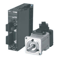
OMRON R88D-KT Series User Manual (553 pages)
Accurax G5 servo system with Analogue/Pulse control; Servo Drives/Servomotors
Brand:
OMRON
| Category:
Engine
| Size: 29.35 MB
Table of Contents
Table of Contents
18
Safety Precautions Document
6
Explanation of Symbols
6
Storage and Transportation
9
Maintenance and Inspection
12
Items to Check after Unpacking
14
Manual Revision History
15
Chapter1
16
Structure of this Document
16
Table of Contents
18
Outline
22
Features of the Accurax G5
22
Outline of the Accurax G5
22
System Configuration
23
Names and Functions
24
Driver Part Names
24
Driver Functions
25
System Block Diagrams
26
Applicable Standards
31
EC Directives
31
Functional Safety
31
UL and Cul Standards
31
Standard Models and External Dimensions
33
Chapter 2 Standard Models and External Dimensions
34
Servo System Configuration
34
How to Read Model
36
Servo Drive
36
Servomotor
37
Standard Model List
38
Servo Drive Model List
38
Servomotor Model List
39
Servo Drive and Servomotor Combination List
43
Peripheral Equipment and Cable Model List
45
Servo Relay Unit Cables for Servo Drives
53
Servo Relay Unit Cables for Position Control Units
54
External and Mounting Dimensions
57
Servo Drive Dimensions
57
Servomotor Dimensions
69
External Regeneration Resistor Dimensions
88
EMC Filter Dimensions
89
Specifications
91
Chapter 3 Specifications
92
Driver Specifications
92
General Specifications
92
Characteristics
93
Main Circuit and Motor Connections
99
Control I/O Connector Specifications (CN1)
104
Control Input Circuits
114
Control Input Details
118
Sensor on Input (Sen)
122
Speed Command Sign Input (Vsign)
127
Zero Speed Designation (Vzero)
127
Torque Command Sign Input (Tsign)
128
Torque Limit Switching (Tlsel)
128
Control Output Circuits
130
Control Output Details
131
Speed Conformity Output (Tgon)
134
Torque Limiting Signal (Tlimt)
134
Encoder Connector Specifications (CN2)
136
External Encoder Connector Specifications (CN4)
136
Monitor Connector Specifications (CN5)
140
USB Connector Specifications (CN7)
141
Safety Connector Specifications (CN8)
142
Overload Characteristics (Electronic Thermal Function)
144
Overload Characteristics Graphs
144
Motor Specifications
145
General Specifications
145
Characteristics
146
Encoder Specifications
173
Cable and Connector Specifications
174
Encoder Cable Specifications
174
Motor Power Cable Specifications
176
Connector Specifications
183
Analog Monitor Cable Specifications
186
Control Cable Specifications
188
Servo Relay Units and Cable Specifications
203
Servo Relay Units and Cable Specifications
204
Position Control Unit-Servo Relay Unit Cable Specifications
212
External Regeneration Resistor Specifications
222
EMC Filter Specifications
224
System Design
225
Chapter 4 System Design
226
Installation Conditions
226
Servo Drive Installation Conditions
226
Servomotor Installation Conditions
228
Gearbox Installation Conditions
231
Wiring
232
Peripheral Equipment Connection Examples
232
Main Circuit and Motor Connections
238
Terminal Block Wire Sizes
242
Wiring Conforming to EMC Directives
246
Wiring Method
246
Selecting Connection Component
250
Surge Absorber
252
Surge Suppressor
256
Regenerative Energy Absorption
260
Calculating the Regenerative Energy
260
Driver Regeneration Absorption Capacity
262
Regenerative Energy Absorption with an External Regeneration Resistor
263
Connecting an External Regeneration Resistor
264
Basic Control Mode
267
Chapter 5 BASIC CONTROL Mode
268
Position Control
268
Parameters Requiring Settings
269
Position Control
269
Related Functions
272
Parameter Block Diagram for POSITION CONTROL Mode
273
Speed Control
274
Outline of Operation
274
Parameters Requiring Settings
274
Related Functions
278
Parameter Block Diagram for SPEED CONTROL Mode
279
Torque Control
280
Outline of Operation
280
Parameters Requiring Settings
280
Related Functions
283
Parameter Block Diagram for TORQUE CONTROL Mode
284
Internally Set Speed Control
285
Outline of Operation
285
Parameters Requiring Settings
285
Operation Example
287
Switching Control
288
Outline of Operation
288
Parameters Requiring Settings
288
Related Functions
290
Full Closing Control
291
Parameters Requiring Settings
292
Parameter Block Diagram for FULL CLOSING CONTROL Mode
299
Applied Functions
301
Chapter 6 Applied Functions
303
Anti-Vibration Control
303
Outline of Operation
303
Adaptive Filter
307
Outline of Operation
307
Parameters Requiring Settings
308
Notch Filter
309
Outline of Operation
309
Parameters Requiring Settings
310
Electronic Gear Function
312
Outline of Operation
312
Parameters Requiring Settings
312
Operation Example
314
Encoder Dividing Function
315
Outline of Operation
315
Parameters Requiring Settings
315
Brake Interlock
320
Outline of Operation
320
Parameters Requiring Settings
320
Precautions for Correct Use of Holding Brake
320
Operation
321
Gain Switching Function
325
Outline of Operation
325
Parameters Requiring Settings
326
Gain Switching 3 Function
333
Operation
333
Outline of Operation
333
Parameters Requiring Settings
333
Torque Limit
334
Outline of Operation
334
Parameters Requiring Settings
334
Sequence I/O Signal
337
Input Signals
337
Outline of Operation
337
Output Signals
340
Forward and Reverse Drive Prohibition Functions
343
Outline of Operation
343
Parameters Requiring Settings
343
Disturbance Observer Function
346
Outline of Operation
346
Operating Procedure
347
Parameters Requiring Settings
347
Friction Torque Compensation Function
348
Outline of Operation
348
Parameters Requiring Settings
348
Operation Example
349
Inertia Ratio Switching Function
350
Operating Procedure
350
Outline of Operation
350
Parameters Requiring Settings
350
Hybrid Vibration Suppression Function
352
Operating Procedure
352
Outline of Operation
352
Parameters Requiring Settings
352
Feed-Forward Function
353
Outline of Operation
353
Parameters Requiring Settings
353
Operating Procedure
354
Instantaneous Speed Observer Function
357
Outline of Operation
357
Parameters Requiring Settings
357
Operating Procedure
358
Chapter7 Safety Function
359
Safe Torque off (STO) Function
360
Operation Example
363
Connection Example
365
Chapter8 Parameters Details
367
Basic Parameters
368
Gain Parameters
376
Vibration Suppression Parameters
387
Analog Control Parameters
392
Interface Monitor Setting Parameters
402
Extended Parameters
412
Special Parameters
425
Operation
431
Chapter9 Operation
431
Operational Procedure
432
Preparing for Operation
433
Items to Check before Turning on the Power Supply
433
Turning on Power Supply
434
Checking Displays
434
Absolute Encoder Setup
435
Using the Front Display
437
Setting the Mode
438
Changing the Mode
438
Monitor Mode
439
Position Command Speed
440
Speed Control Command
440
Total Encoder Pulses
441
Total Command Pulses
441
Total External Scale Feedback Pulses
441
Control Mode
442
I/O Signal Status
442
Analog Input Value
443
Error Factor, History
443
Warning Number
445
Display of the Number of I/O Signal Changes
447
Absolute Encoder Data
447
Absolute External Scale Position
448
Display of Axis Numbers for Communication
448
P-N Voltage
450
Soft Version
450
Accumulative Operation Time
451
Automatic Motor Recognition Function
451
Parameter Setting Mode
453
Parameter Write Mode
455
Auxiliary Function Mode
456
Jog Operation
458
Trial Operation
464
Preparation for Trial Operation
464
Trial Operation in Position Control Mode
465
Trial Operation in Speed Control Mode
466
Trial Operation in Torque Control Mode
467
Trial Operation in Full Closing Control Mode
468
Chapter10 Adjustment Functions
469
Gain Adjustment
470
Gain Adjustment Methods
470
Purpose of the Gain Adjustment
470
Gain Adjustment Procedure
471
Realtime Autotuning
472
Setting Machine Rigidity
473
Setting Realtime Autotuning
473
Manual Tuning
479
Basic Settings
479
Speed Control Mode Adjustment
481
Torque Control Mode Adjustment
486
Error and Maintenance
487
Chapter11 Error And Maintenance
487
Error Processing
488
Preliminary Checks When a Problem Occurs
488
Precautions When a Problem Occurs
489
Replacing the Servomotor and Servo Drive
490
Warning List
491
Alarm List
492
Troubleshooting
497
Error Diagnosis Using the Alarm Displays
497
Error Diagnosis Using the Operation Status
504
Periodic Maintenance
508
Servomotor Limit
508
Servo Drive Limit
509
Chapter12 Appendix
513
Connection Examples
514
Parameter List
524
12-2 Parameter List
541
Safety Certification
545
Advertisement
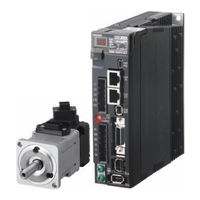
Omron R88D-KT Series User Manual (632 pages)
AC SERVOMOTORS/SERVO DRIVES
Brand:
Omron
| Category:
Servo Drives
| Size: 42.98 MB
Table of Contents
Table of Contents
20
Safety Precautions
8
Items to Check after Unpacking
16
Revision History
17
Structure of this Document
18
Table of Contents
20
Chapter 1 Features and System Configuration
24
Outline
24
Features of OMNUC G5-Series Servo Drives
24
Outline of the OMNUC G5 Series
24
System Configuration
25
Names and Functions
26
Servo Drive Part Names
26
Servo Drive Functions
27
System Block Diagrams
28
Applicable Standards
38
EC Directives
38
UL and Cul Standards
38
Korean Radio Regulations (KC)
39
Semi F47
40
Unit Versions
41
Confirmation Method
41
Standard Models and External Dimensions
43
Chapter 2 Standard Models and External Dimensions
44
Servo System Configuration
44
How to Read Model Numbers
46
Servo Drive
46
Servomotor
47
Standard Model Tables
48
Servo Drive Model Table
48
Servomotor Model Tables
49
Servo Drive and Servomotor Combination Tables
54
Peripheral Equipment and Cable Model Tables
56
External and Mounting Dimensions
68
Servo Drive Dimensions
68
Servomotor Dimensions
86
External Regeneration Resistor Dimensions
113
EMC Filter Dimensions
114
Dimensions of Mounting Brackets (L-Brackets for Rack Mounting)
115
Specifications
117
Chapter 3 Specifications
118
Servo Drive Specifications
118
General Specifications
118
Characteristics
119
Main Circuit and Motor Connections
126
Control I/O Connector Specifications (CN1)
135
Control Input Circuits
145
Control Input Details
149
Control Output Circuits
162
Control Output Details
163
Encoder Connector Specifications (CN2)
168
External Encoder Connector Specifications (CN4)
168
Analog Monitor Connector Specifications (CN5)
171
Safety Connector Specifications (CN8)
172
USB Connector Specifications (CN7)
172
Overload Characteristics (Electronic Thermal Function)
175
Overload Characteristics Graphs
175
Servomotor Specifications
176
General Specifications
176
Characteristics
177
Encoder Specifications
213
Cable and Connector Specifications
214
Encoder Cable Specifications
214
Motor Power Cable Specifications
217
Connector Specifications
224
Analog Monitor Cable Specifications
228
Control Cable Specifications
229
Servo Relay Units and Cable Specifications
244
Servo Relay Units and Cable Specifications
246
Position Control Unit-Servo Relay Unit Cable Specifications
253
External Regeneration Resistor Specifications
263
EMC Filter Specifications
265
System Design
267
Chapter 4 System Design
268
Installation Conditions
268
Space Conditions Around Servo Drives
268
Servomotor Installation Conditions
270
Decelerator Installation Conditions
273
Wiring
274
Peripheral Equipment Connection Examples
275
Main Circuit and Motor Connections
285
Wiring Conforming to EMC Directives
300
Wiring Method
300
Selecting Connection Component
308
Regenerative Energy Absorption
320
Regenerative Energy Calculation
320
Servo Drive Regeneration Absorption Capacity
323
Regenerative Energy Absorption with an External Regeneration Resistor
324
Connecting an External Regeneration Resistor
325
Large Load Inertia Adjustment and Dynamic Brake
328
Adjustment When the Load Inertia Is Large
328
Dynamic Brake When the Load Inertia Is Large
328
Using DC Power
329
Connection Examples for DC Power
330
Chapter5 Basic Control Mode
333
Position Control
334
Speed Control
340
Torque Control
347
Internally Set Speed Control
352
Switching Control
356
Fully-Closed Control
359
Chapter6 Applied Functions
369
Damping Control
371
Adaptive Filter
375
Notch Filter
377
Electronic Gear Function
380
Encoder Dividing Function
384
Brake Interlock
389
Gain Switching Function
394
Torque Limit
402
Sequence I/O Signal
405
Forward and Reverse Drive Prohibition Functions
411
Disturbance Observer Function
414
Gain Switching 3 Function
416
Friction Torque Compensation Function
417
Inertia Ratio Switching Function
419
Hybrid Vibration Suppression Function
420
Feed-Forward Function
421
Instantaneous Speed Observer Function
425
Chapter7 Safety Function
427
Safe Torque off (STO) Function
428
Operation Example
431
Connection Example
433
Chapter8 Parameter Details
435
Basic Parameters
436
Gain Parameters
444
Vibration Suppression Parameters
455
Analog Control Parameters
460
Interface Monitor Setting Parameters
472
Extended Parameters
482
Special Parameters
495
Chapter9 Operation
504
Operational Procedure
504
Preparing for Operation
505
Using the Front Display
509
Setting the Mode
510
Trial Operation
536
Chapter10 Adjustment Functions
541
Gain Adjustment
542
Realtime Autotuning
544
Manual Tuning
551
Chapter11 Troubleshooting And Maintenance
559
Troubleshooting
560
Warning List
563
Alarm List
564
Troubleshooting
569
Periodic Maintenance
586
Chapter12 Appendix
591
Connection Examples
592
Parameter List
602
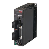
Omron R88D-KT Series User Manual (634 pages)
AC SERVOMOTORS/SERVO DRIVES
Brand:
Omron
| Category:
Servo Drives
| Size: 9.31 MB
Table of Contents
Safety Precautions
8
Items to Check after Unpacking
19
Revision History
20
Structure of this Document
21
Chapter1
21
Table of Contents
22
Outline
26
Outline of the OMNUC G5 Series
26
Features of OMNUC G5-Series Servo Drives
26
System Configuration
27
Names and Functions
28
Servo Drive Part Names
28
Servo Drive Functions
29
System Block Diagrams
30
Applicable Standards
40
EC Directives
40
UL and Cul Standards
40
Korean Radio Regulations (KC)
41
Semi F47
42
Unit Versions
43
Confirmation Method
43
Servo System Configuration
46
How to Read Model Numbers
48
Servo Drive
48
Servomotor
49
Standard Model Tables
50
Servo Drive Model Table
50
Servomotor Model Tables
51
Servo Drive and Servomotor Combination Tables
56
Peripheral Equipment and Cable Model Tables
58
External and Mounting Dimensions
70
Servo Drive Dimensions
70
Servomotor Dimensions
88
External Regeneration Resistor Dimensions
115
EMC Filter Dimensions
116
Dimensions of Mounting Brackets (L-Brackets for Rack Mounting)
117
Servo Drive Specifications
120
General Specifications
120
Characteristics
121
Main Circuit and Motor Connections
128
Control I/O Connector Specifications (CN1)
137
Control Input Circuits
147
Control Input Details
151
Control Output Circuits
164
Control Output Details
165
Encoder Connector Specifications (CN2)
170
External Encoder Connector Specifications (CN4)
170
Analog Monitor Connector Specifications (CN5)
173
USB Connector Specifications (CN7)
174
Safety Connector Specifications (CN8)
174
Overload Characteristics (Electronic Thermal Function)
177
Overload Characteristics Graphs
177
Servomotor Specifications
178
General Specifications
178
Characteristics
179
Encoder Specifications
215
Cable and Connector Specifications
216
Encoder Cable Specifications
216
Motor Power Cable Specifications
219
Connector Specifications
226
Analog Monitor Cable Specifications
230
Control Cable Specifications
231
Servo Relay Units and Cable Specifications
246
Servo Relay Units Specifications
246
Position Control Unit-Servo Relay Unit Cable Specifications
255
External Regeneration Resistor Specifications
265
EMC Filter Specifications
267
Installation Conditions
270
Space Conditions Around Servo Drives
270
Servomotor Installation Conditions
272
Decelerator Installation Conditions
275
Wiring
276
Peripheral Equipment Connection Examples
277
Main Circuit and Motor Connections
287
Wiring Conforming to EMC Directives
302
Wiring Method
302
Selecting Connection Component
310
Regenerative Energy Absorption
322
Regenerative Energy Calculation
322
Servo Drive Regeneration Absorption Capacity
325
Regenerative Energy Absorption with an External Regeneration Resistor
326
Connecting an External Regeneration Resistor
327
Large Load Inertia Adjustment and Dynamic Brake
330
Adjustment When the Load Inertia Is Large
330
Dynamic Brake When the Load Inertia Is Large
330
Using DC Power
331
Connection Examples for DC Power
332
Chapter5 Basic Control Mode
335
Position Control
336
Speed Control
342
Torque Control
349
Internally Set Speed Control
354
Switching Control
358
Fully-Closed Control
361
Chapter6 Applied Functions
371
Damping Control
373
Adaptive Filter
377
Notch Filter
379
Electronic Gear Function
382
Encoder Dividing Function
386
Brake Interlock
391
Gain Switching Function
396
Torque Limit
404
Sequence I/O Signal
407
Forward and Reverse Drive Prohibition Functions
413
Disturbance Observer Function
416
Gain Switching 3 Function
418
Friction Torque Compensation Function
419
Inertia Ratio Switching Function
421
Hybrid Vibration Suppression Function
422
Feed-Forward Function
423
Instantaneous Speed Observer Function
427
Chapter7 Safety Function
429
Safe Torque off (STO) Function
430
Operation Example
433
Connection Example
435
Chapter8 Parameter Details
437
Basic Parameters
438
Gain Parameters
446
Vibration Suppression Parameters
457
Analog Control Parameters
462
Interface Monitor Setting Parameters
474
Extended Parameters
484
Special Parameters
497
Chapter9 Operation
505
Operational Procedure
506
Preparing for Operation
507
Using the Front Display
511
Setting the Mode
512
Trial Operation
538
Chapter10 Adjustment Functions
543
Gain Adjustment
544
Realtime Autotuning
546
Manual Tuning
553
Chapter11 Troubleshooting And Maintenance
561
Troubleshooting
562
Warning List
565
Alarm List
566
Troubleshooting
571
Periodic Maintenance
588
Chapter12 Appendix
593
Connection Examples
594
Parameter List
604
Index
627
Advertisement
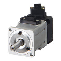
OMRON R88D-KT Series User Manual (550 pages)
AC SERVOMOTORS/SERVO DRIVES
Brand:
OMRON
| Category:
Computer Hardware
| Size: 39.02 MB
Table of Contents
Table of Contents
16
Safety Precautions Document
6
Items to Check after Unpacking
13
Manual Revision History
14
Structure of this Document
15
Table of Contents
16
Chapter 1 Features and System Configuration
20
Outline
20
Features of the OMNUC G5 Series
20
Outline of the OMNUC G5 Series
20
System Configuration
21
Names and Functions
22
Driver Part Names
22
Driver Functions
23
System Block Diagrams
24
Applicable Standards
25
EC Directives
25
Functional Safety
25
UL and Cul Standards
25
Standard Models and External Dimensions
27
Chapter 2 Standard Models and External Dimensions
28
Servo System Configuration
28
How to Read Model
30
Servo Drive
30
Servomotor
31
Standard Model List
32
Servo Drive Model List
32
Servomotor Model List
33
Servo Drive and Servomotor Combination List
37
Peripheral Equipment and Cable Model List
39
External and Mounting Dimensions
49
Servo Drive Dimensions
49
Servomotor Dimensions
61
External Regeneration Resistor Dimensions
80
EMC Filter Dimensions
81
Specifications
83
Chapter 3 Specifications
84
Driver Specifications
84
General Specifications
84
Characteristics
85
Main Circuit and Motor Connections
91
Control I/O Connector Specifications (CN1)
96
Control Input Circuits
106
Control Input Details
110
Control Output Circuits
122
Control Output Details
123
Encoder Connector Specifications (CN2)
128
External Encoder Connector Specifications (CN4)
128
Monitor Connector Specifications (CN5)
132
USB Connector Specifications (CN7)
133
Safety Connector Specifications (CN8)
134
Overload Characteristics (Electronic Thermal Function)
136
Overload Characteristics Graphs
136
Motor Specifications
137
General Specifications
137
Characteristics
138
Encoder Specifications
160
Cable and Connector Specifications
161
Encoder Cable Specifications
161
Motor Power Cable Specifications
163
Connector Specifications
169
Analog Monitor Cable Specifications
172
Control Cable Specifications
174
Servo Relay Units and Cable Specifications
189
Servo Relay Units Specifications
189
Servo Drive-Servo Relay Unit Cable Specifications
202
Position Control Unit-Servo Relay Unit Cable Specifications
206
External Regeneration Resistor Specifications
219
EMC Filter Specifications
221
System Design
223
Chapter 4 System Design
224
Installation Conditions
224
Servo Drive Installation Conditions
224
Servomotor Installation Conditions
226
Gearbox Installation Conditions
229
Wiring
230
Peripheral Equipment Connection Examples
230
Main Circuit and Motor Connections
236
Wiring Conforming to EMC Directives
244
Wiring Method
244
Selecting Connection Component
248
Regenerative Energy Absorption
260
Calculating the Regenerative Energy
260
Driver Regeneration Absorption Capacity
262
Regenerative Energy Absorption with an External Regeneration Resistor
263
Connecting an External Regeneration Resistor
264
Basic Control Mode
267
Chapter 5 BASIC CONTROL Mode
268
Position Control
268
Outline of Operation
268
Parameters Requiring Settings
269
Related Functions
271
Parameter Block Diagram for POSITION CONTROL Mode
272
Speed Control
273
Outline of Operation
273
Parameters Requiring Settings
273
Related Functions
277
Parameter Block Diagram for SPEED CONTROL Mode
278
Torque Control
279
Outline of Operation
279
Parameters Requiring Settings
279
Related Functions
282
Parameter Block Diagram for TORQUE CONTROL Mode
283
Internally Set Speed Control
284
Outline of Operation
284
Parameters Requiring Settings
284
Switching Control
287
Outline of Operation
287
Parameters Requiring Settings
287
Related Functions
289
Full Closing Control
290
Full Closing Control
291
Parameters Requiring Settings
291
Parameter Block Diagram for FULL CLOSING CONTROL Mode
298
Chapter6 Applied Functions
299
Damping Control
301
Adaptive Filter
305
Notch Filter
307
Electronic Gear Function
310
Encoder Dividing Function
313
Brake Interlock
318
Gain Switching Function
323
Torque Limit
331
Sequence I/O Signal
334
Forward and Reverse Drive Prohibition Functions
340
Disturbance Observer Function
343
Gain Switching 3 Function
345
Friction Torque Compensation Function
346
Inertia Ratio Switching Function
348
Hybrid Vibration Suppression Function
349
Feed-Forward Function
350
Instantaneous Speed Observer Function
354
Chapter7 Safety Function
357
Safe Torque off (STO) Function
358
Operation Example
361
Connection Examples
363
Chapter8 Parameters Details
365
Basic Parameters
366
Gain Parameters
374
Vibration Suppression Parameters
385
Analog Control Parameters
390
Interface Monitor Setting Parameters
401
Extended Parameters
411
Special Parameters
424
Chapter9 Operation
431
Operational Procedure
432
Preparing for Operation
433
Using the Front Display
437
Setting the Mode
438
Trial Operation
464
Chapter10 Adjustment Functions
469
Gain Adjustment
470
Realtime Autotuning
472
Manual Tuning
479
Chapter11 Error And Maintenance
487
Error Processing
488
Warning List
491
Alarm List
492
Troubleshooting
496
Periodic Maintenance
507
Chapter12 Appendix
511
Connection Examples
512
Parameter List
522
Index
543
Omron R88D-KT Series Manual (42 pages)
AC Servomotor/Servo Drives
Brand:
Omron
| Category:
DC Drives
| Size: 1.49 MB
Table of Contents
Introduction
3
Intended Audience
3
Applicable Products
3
Terms and Conditions Agreement
4
Precautions
6
Trademarks
6
Revision History
7
Table of Contents
8
Outline
9
Precautions for Replacement
10
Replacement List
11
Servomotors with Rated Rotation Speed of 3,000 R/Min
11
Flat Servomotors with Rated Rotation Speed of 3,000 R/Min
11
Comparison of Servomotor Dimensions
12
Servomotors with Rated Rotation Speed of 3,000 R/Min (Main Circuit Power Supply Voltage: 100 V or 200 V)
12
Comparison of Servo Drive Dimensions
15
Layout and Specifications of Connectors and Terminal Blocks of Servo Drive
16
Layout and Specifications of Connectors and Terminal Blocks of Main Circuit Wiring and Motor Wiring
16
Layout and Specifications of Connectors of Control Circuit
17
Gain Adjustment Methods
22
Gain Adjustment Method (Auto Tuning)
22
Using Gain Adjustment Values for SS2 Series as those for G5 Series
27
Connecting with Host Controllers
28
Detailed Comparison of Parameters
29
Function Selection Parameters
29
Parameters Related to Gain
31
Parameters Related to Position Control
35
Parameters Related to Internally Set Speed Control
37
Parameters Related to Sequence
38
Appendix. List of Cables Connecting G5-Series Servo Drives and Servomotors
41
Advertisement
Related Products
Omron R88D-KTA5L
Omron R88D-KT01L
Omron R88D-KT02L
Omron R88D-KT04L
Omron R88DKT20H
Omron R88DKT30H
Omron R88DKT50H
Omron R88DKT75H
Omron R88DKT150H
Omron R88D-KT75F
Omron Categories
Blood Pressure Monitor
Controller
Accessories
Switch
Inverter
More Omron Manuals
Login
Sign In
OR
Sign in with Facebook
Sign in with Google
Upload manual
Upload from disk
Upload from URL