
Related Manuals for Omron R88D-KNA5L-ML2


Summary of Contents for Omron R88D-KNA5L-ML2
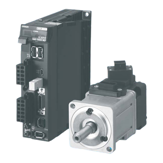
- Page 1 Cat. No. I572-E2-02 Accurax G5 servo system with built-in MECHATROLINK-II Model: R88D-KN_-ML2 Servo Drives R88M-K_ Servomotors USER’S MANUAL WWW.BSNEW.IR...
- Page 2 WWW.BSNEW.IR...
- Page 3 Introduction Introduction Thank you for purchasing the Accurax G5 Series. This user's manual explains how to install and wire the Accurax G5 Series, set parameters needed to operate the G5 Series, and remedies to be taken and inspection methods to be used should problems occur. Intended Readers This manual is intended for the following individuals.
- Page 4 Failure that could not be predicted with the level of science and technology available when the product was shipped from OMRON f) Failure caused by a natural disaster or any other reason for which OMRON is not held responsible Take note that this warranty applies to the product itself, and losses induced by a failure of the product are excluded from the scope of warranty.
- Page 5 5. Scope of Service The price of this product excludes costs of service such as dispatching engineers. If you have any request regarding service, consult your OMRON sales representative. OMNUC G5-Series AC Servo Drives Users Manual (Built-in MECHATROLINK-II communications type)
-
Page 6: Safety Precautions Document
Safety Precautions Document Safety Precautions Document So that the Accurax G5-Series Servomotor and Servo Drive and peripheral equipment are used safely and correctly, be sure to peruse this Safety Precautions document section and the main text before using the product in order to learn all items you should know regarding the equipment as well as all safety information and precautions. - Page 7 When using this product, be sure to install the covers and shields as specified and use the product according to this manual. If the product has been stored for an extended period of time, contact your OMRON sales representative. Danger Be sure to ground the frame ground terminals of the Servo Drive and motor to 100 Ω...
- Page 8 Safety Precautions Document Danger Do not place flammable materials near the motor, Servo Drive or Regeneration Resistor. Fire may result. Install the motor, Servo Drive and Regeneration Resistor to non-flammable materials such as metals. Fire may result. When you perform a system configuration using the safety function, be sure to fully understand the relevant safety standards and the descriptions in the operation manual, and apply them to the system design.
- Page 9 Safety Precautions Document Storage and Transportation Caution When transporting the product, do not hold it by the cables or motor shaft. Injury or failure may result. Do not overload the products. (Follow the instruction on the product label.) Injury or failure may result. Use the motor eye-bolts only when transporting the motor.
- Page 10 Safety Precautions Document Installation and Wiring Caution Do not step on the product or place heavy articles on it. Injury may result. Do not block the intake or exhaust openings. Do not allow foreign objects to enter the product. Fire may result. Be sure to observe the mounting direction.
- Page 11 Safety Precautions Document Operation and Adjustment Caution Conduct a test operation after confirming that the equipment is not affected. Equipment damage may result. Before operating the product in an actual environment, check if it operates correctly based on the parameters you have set. Equipment damage may result.
- Page 12 Safety Precautions Document Location of Warning Label This product bears a warning label at the following location to provide handling warnings. When handling the product, be sure to observe the instructions provided on this label. Warning label display location (R88D-KN02H-ML2) Instructions on Warning Label Disposal When disposing of the battery, insulate it using tape, etc.
-
Page 13: Items To Check After Unpacking
Connectors, mounting screws, etc. other than those in the table below are not supplied. They must be prepared by the customer. If any item is missing or a problem is found such as Servo Drive damage, contact the OMRON dealer or sales office where you purchased your product. -
Page 14: Manual Revision History
Manual Revision History Manual Revision History The manual revision symbol is an alphabet appended at the end of the manual number found in the bottom left-hand corner of the front or back cover. Example I572-E2-01 Revision Revision date Description of revision and revised page symbol March 2009 First print... -
Page 15: Structure Of This Document
Structure of This Document Structure of This Document This manual consists of the following chapters. Read the necessary chapter or chapters referring to below. Outline Features and This chapter explains the features of this product, name of each part, Chapter 1 System and applicable EC directives and UL standards. -
Page 16: Table Of Contents
Table Of Contents Introduction ....................1 Items Requiring Acknowledgment ............2 Safety Precautions Document ...............4 Items to Check after Unpacking ............11 Manual Revision History ..............12 Structure of This Document ..............13 Chapter1 Features and System Configuration Outline ....................1-1 Outline of the OMNUC G5 Series ................1-1 Features of the OMNUC G5 Series ................1-1 System Configuration ................ - Page 17 Table Of Contents Control I/O Connector Specifications (CN1) .............. 3-13 Control Input Circuits ....................3-15 Control Input Details ....................3-16 Control Output Circuits ....................3-18 Control Output Details ....................3-19 Encoder Connector Specifications (CN2) ..............3-23 External Encoder Connector Specifications (CN4)............ 3-23 Monitor Connector Specifications (CN5) ..............
- Page 18 Table Of Contents Chapter5 BASIC CONTROL Mode Position Control ..................5-1 Parameters Requiring Settings ..................5-1 Related Functions ......................5-2 Parameter Block Diagram for POSITION CONTROL mode ........5-3 Speed Control ..................5-4 Parameters Requiring Settings ..................5-4 Related Functions ......................5-4 Parameter Block Diagram for SPEED CONTROL mode ..........5-5 Torque Control ..................
- Page 19 Table Of Contents 6-10 Gain Switching 3 Function..............6-36 Operating Conditions ....................6-36 Parameters Requiring Settings.................. 6-36 Operation Example ....................6-37 Chapter7 Safety Function Safe Torque OFF (STO) Function ............7-1 Functional Safety ......................7-1 I/O Signal Specifications....................7-2 Operation Example.................7-4 Connection Examples................7-6 Chapter8 Parameters Details Basic Parameters ...................8-1 Gain Parameters ..................8-8...
- Page 20 Table Of Contents Basic Settings ......................10-13 10-5 Damping Control ................10-21 Outline of Operation ....................10-21 Parameters Requiring Settings ................10-22 10-6 Adaptive Filter ................... 10-25 Parameters Requiring Settings ................10-26 Operating Procedure ....................10-27 10-7 Notch Filter ..................10-28 Parameters Requiring Settings ................10-29 10-8 Disturbance Observer Function ............
- Page 21 Table Of Contents Appendix Parameter List ..................A-1 Index OMNUC G5-Series AC Servo Drives Users Manual (Built-in MECHATROLINK-II communications type) WWW.BSNEW.IR...
- Page 22 WWW.BSNEW.IR...
- Page 23 Features and System Configuration This chapter explains the features of this product, name of each part, and applicable EC directives and UL standards. 1-1 Outline ................1-1 1-2 System Configuration ..........1-3 1-3 Names and Functions ..........1-4 1-4 System Block Diagrams..........1-6 1-5 Applicable Standards ..........1-11 OMNUC G5-Series AC Servo Drives Users Manual (Built-in MECHATROLINK-II communications type) WWW.BSNEW.IR...
-
Page 24: Outline
1-1 Outline 1-1 Outline Outline of the Accurax G5 Series The Accurax G5-Series AC Servo Drives (Built-in MECHATROLINK-II communications support type) are a series of Servo Drives supporting the MECHATROLINK-II high-speed motion field network. When you use it with the MECHATROLINK-II Position Control Unit (CJ1W-NCF71, CS1W- NCF71, CJ1W-MCH72 or other), you can create a sophisticated positioning control system. - Page 25 1-1 Outline Two damping filters are provided to enable switching the damping frequency automatically according to the rotation direction and also via an external signal. In addition, the settings can be made easily merely by just setting the damping frequency and filter values, and you are assured of stable operation even if the set values are inappropriate.
-
Page 26: System Configuration
1-2 System Configuration 1-2 System Configuration OMNUC G5-Series AC Servo Drives Users Manual (Built-in MECHATROLINK-II communications type) WWW.BSNEW.IR... -
Page 27: Names And Functions
1-3 Names and Functions 1-3 Names and Functions This section describes the name and functions of the Servo Drive. Servo Drive Part Names The Servo Drive Part Names are defined as shown below. MECHATROLINK-II status LED indicator Display area Analog monitor connector (CN5) Rotary switches for node address setting MECHATROLINK-II... -
Page 28: Servo Drive Functions
1-3 Names and Functions Servo Drive Functions The functions of each part are the followings: Display Area A 2-digit 7-segment LED indicator shows the node address, alarm codes, and other Servo Drive status. Charge Lamp Lits when the main circuit power supply is turned ON. MECHATROLINK-II Status LED Indicator Indicates the communications status of the MECHATROLINK-II. -
Page 29: System Block Diagrams
1-4 System Block Diagrams 1-4 System Block Diagrams Size A: R88D-KNA5L/-01L/-01H/-02H-ML2 Size B: R88D-KN02L/-04H-ML2 Size C: R88D-KN04L/-08H-ML2 − − ± • OMNUC G5-Series AC Servo Drives Users Manual (Built-in MECHATROLINK-II communications type) WWW.BSNEW.IR... -
Page 30: System Block Diagrams
1-4 System Block Diagrams Size D: R88D-KN10H/-15H-ML2 − − ± • OMNUC G5-Series AC Servo Drives Users Manual (Built-in MECHATROLINK-II communications type) WWW.BSNEW.IR... - Page 31 1-4 System Block Diagrams Size D: R88D-KN06F/-10F/-15F-ML2 CN D CN A FUSE Internal Regen Resistor FUSE Fuse (not installed) CN B − CN C Voltage detection FUSE DC-DC − − SW power 15 V Relay Overcurrent Regeneration Current detection supply main Gate drive drive control...
- Page 32 1-4 System Block Diagrams Size E: R88D-KN20H-ML2 Size F: R88D-KN30H/-50H-ML2 CN C CN A FUSE Internal Regen Resistor Fuse (not installed) FUSE − CN B Voltage detection FUSE − SW power 15 V Relay Regeneration Overcurrent G G G R R R Current detection supply main Gate drive...
- Page 33 1-4 System Block Diagrams Size E: R88D-KN20F-ML2 Size F: R88D-KN30F/-50F-ML2 CN D CN A FUSE Internal Regen Resistor FUSE Fuse (not installed) CN B − CN C Voltage detection FUSE DC-DC − − SW power 15 V Relay Regeneration Overcurrent Current detection supply main Gate drive...
-
Page 34: Applicable Standards
1-5 Applicable Standards 1-5 Applicable Standards This section describes applicable EMC Directives. EC Directives Product Applicable standards directive Low voltage AC Servo Drive EN 61800-5-1 command AC Servomotor EN60034-1/-5 AC Servo Drive EN 55011 class A group 1 directives AC Servomotor IEC61800-3 EN61000-6-2 Note. - Page 35 Standard Models and External Dimensions Accurax This chapter explains the models of Servo Drive, Servomotor, and peripheral equipment, as well as the external dimensions and mounting dimensions. 2-1 Servo System Configuration ........2-1 2-2 How to Read Model............2-3 2-3 Standard Model List .............2-5 2-4 External and Mounting Dimensions......2-21 2-5 EMC Filter Dimensions..........2-52 OMNUC G5-Series AC Servo Drives Users Manual (Built-in MECHATROLINK-II communications type)
-
Page 36: Servo System Configuration
2-1 Servo System Configuration 2-1 Servo System Configuration OMNUC G5-Series AC Servo Drives Users Manual (Built-in MECHATROLINK-II communications type) WWW.BSNEW.IR... - Page 37 2-1 Servo System Configuration • • ML 2 ML 2 • • “ ” OMNUC G5-Series AC Servo Drives Users Manual (Built-in MECHATROLINK-II communications type) WWW.BSNEW.IR...
-
Page 38: How To Read Model
2-2 How to Read Model 2-2 How to Read Model This section describes how to read and understand the model numbers for Servo Drives and Servomotors. Servo Drive The Servo Drive model can be identified by the Servo Drive type, applicable Servomotor capacity, power supply voltage, etc. -
Page 39: Servomotor
2-2 How to Read Model Servomotor The model number provides information such as the Servomotor type, applicable motor capacity, rated rotation speed, and power supply voltage. OMNUC G5-Series AC Servo Drives Users Manual (Built-in MECHATROLINK-II communications type) WWW.BSNEW.IR... -
Page 40: Standard Model List
This section lists the standard models of Servo Drives, Servomotors, Cables, Connectors, and peripheral equipment. Servo Drive Model List The table below lists the Servo Drive models. Specifications Model Single-phase 100 VAC 50 W R88D-KNA5L-ML2 100 W R88D-KN01L-ML2 200 W R88D-KN02L-ML2 400 W R88D-KN04L-ML2 Single-phase/3-phase 200 VAC... -
Page 41: Servomotor Model List
2-3 Standard Model List Servomotor Model List The table below lists the Servomotor models by rated number of motor rotations. 3,000-r/min Servomotors Model With incremental encoder With absolute encoder Specifications Straight shaft Straight shaft Straight shaft Straight shaft without key with key and tap without key with key and tap... - Page 42 2-3 Standard Model List Model With incremental encoder With absolute encoder Specifications Straight shaft Straight shaft Straight shaft Straight shaft without key with key and tap without key with key and tap 50 W R88M-K05030L-B R88M-K05030L-BS2 R88M-K05030S-B R88M-K05030S-BS2 100 W R88M-K10030L-B R88M-K10030L-BS2 R88M-K10030S-B R88M-K10030S-BS2...
- Page 43 2-3 Standard Model List 2,000-r/min Servomotors Model With incremental encoder With absolute encoder Specifications Straight shaft Straight shaft Straight shaft Straight shaft without key with key and tap without key with key and tap 1 kW R88M-K1K020H R88M-K1K020H-S2 R88M-K1K020T R88M-K1K020T-S2 1.5 kW R88M-K1K520H R88M-K1K520H-S2 R88M-K1K520T...
- Page 44 2-3 Standard Model List 1,000-r/min Servomotors Model With incremental encoder With absolute encoder Specifications Straight shaft Straight shaft Straight shaft Straight shaft without key with key and tap without key with key and tap 900 kW R88M-K90010H R88M-K90010H-S2 R88M-K90010T R88M-K90010T-S2 200 V 2 kW R88M-K2K010H R88M-K2K010H-S2...
-
Page 45: Servo Drive And Servomotor Combination List
3,000-r/min Servomotors and Servo Drives Servomotor Voltage Servo Drive Rated With incremental With absolute output encoder encoder 50 W R88M-K05030L-x R88M-K05030S-x R88D-KNA5L-ML2 100 W R88M-K10030L-x R88M-K10030S-x R88D-KN01L-ML2 Single-phase 100 V 200 W R88M-K20030L-x R88M-K20030S-x R88D-KN02L-ML2 400 W R88M-K40030L-x R88M-K40030S-x... - Page 46 2-3 Standard Model List 2,000-r/min Servomotors and Servo Drives Servomotor Voltage Servo Drive Rated With incremental With absolute output encoder encoder 1 kW R88M-K1K020H-x R88M-K1K020T-x R88D-KN10H-ML2 Single-phase/ 3-phase 200 V 1.5 kW R88M-K1K520H-x R88M-K1K520T-x R88D-KN15H-ML2 2 kW R88M-K2K020H-x R88M-K2K020T-x R88D-KN20H-ML2 3 kW R88M-K3K020H-x R88M-K3K020T-x...
-
Page 47: Cables And Peripheral Devices Model List
2-3 Standard Model List Cables and Peripheral Devices Model List The table below lists the models of cables and peripheral devices. The cable include encoder cables, motor power cables, MECHATROLINK-II communications cables, and absolute encoder battery cables. The peripheral devices include External Regeneration Resistors. Encoder Cables (European Flexible Cables) Specifications Model... - Page 48 2-3 Standard Model List Motor Power Cables (European Flexible Cables) Model Specifications For motor without For motor with brake brake [100 V and 200 V] 1.5 m R88A-CAKA001-5SR-E For 3,000-r/min motors of 50 to 750 W It requires both, the R88A-CAKA003SR-E power cable R88A-- R88A-CAKA005SR-E...
- Page 49 2-3 Standard Model List Brake Cables (European Flexible Cables) Specifications Model [100 V and 200 V] 1.5 m R88A-CAKA001-5BR-E For 3,000-r/min motors of 50 to 750 W R88A-CAKA003BR-E R88A-CAKA005BR-E 10 m R88A-CAKA010BR-E 15 m R88A-CAKA015BR-E 20 m R88A-CAKA020BR-E Encoder Cables (Japanese Non-Flexible Cables) Specifications Model [100 V and 200 V]...
- Page 50 2-3 Standard Model List Motor Power Cables (Japanese Non-Flexible Cables) Model Specifications For motor without For motor with brake brake [100 V and 200 V] R88A-CAKA003S For 3,000-r/min motors of 50 to 750 W R88A-CAKA005S 10 m R88A-CAKA010S It requires both, the power cable R88A-- 15 m R88A-CAKA015S...
- Page 51 2-3 Standard Model List Brake Cables (Japanese Non-Flexible Cables) Specifications Model [100 V and 200 V] R88A-CAKA003B For 3,000-r/min motors of 50 to 750 W R88A-CAKA005B 10 m R88A-CAKA010B 15 m R88A-CAKA015B 20 m R88A-CAKA020B 30 m R88A-CAKA030B 40 m R88A-CAKA040B 50 m R88A-CAKA050B...
- Page 52 2-3 Standard Model List Motor Power Cables (Japanese Flexible Cables) Model Specifications For motor without For motor with brake brake [100 V and 200 V] R88A-CAKA003SR For 3,000-r/min motors of 50 to 750 W R88A-CAKA005SR 10 m R88A-CAKA010SR It requires both, the power cable R88A-- 15 m R88A-CAKA015SR...
- Page 53 2-3 Standard Model List Brake Cables (Japanese Flexible Cables) Specifications Model [100 V and 200 V] R88A-CAKA003BR For 3,000-r/min motors of 50 to 750 W R88A-CAKA005BR 10 m R88A-CAKA010BR 15 m R88A-CAKA015BR 20 m R88A-CAKA020BR 30 m R88A-CAKA030BR 40 m R88A-CAKA040BR 50 m R88A-CAKA050BR...
- Page 54 2-3 Standard Model List Absolute Encoder Battery Cables Specifications Model ABS battery cable (battery not supplied) 0.3 m R88A-CRGD0R3C ABS battery cable (R88A-BAT01G battery × 1 supplied) 0.3 m R88A-CRGD0R3C-BS Absolute Encoder Backup Battery Specifications Model 2,000 mA•h 3.6 V R88A-BAT01G Analog Monitor Cable Specifications...
- Page 55 Regeneration process capacity: 70 W, 47 Ω (with 170°C thermal sensor) R88A-RR22047S Regeneration process capacity: 180 W, 20 Ω (with 200°C thermal sensor) R88A-RR50020S Mounting Brackets (L-Brackets for Rack Mounting) Specifications Model R88D-KNA5L-ML2/-KN01L-ML2/-KN01H-ML2/-KN02H-ML2 R88A-TK01K R88D-KN02L-ML2/-KN04H-ML2 R88A-TK02K R88D-KN04L-ML2/-KN08H-ML2 R88A-TK03K R88D-KN10H-ML2/-KN15H-ML2/-KN06F-ML2/-KN10F-ML2/-KN15F-ML2 R88A-TK04K...
-
Page 56: External And Mounting Dimensions
The dimensional description starts with a Servo Drive of the smallest motor capacity, which is followed by the next smallest, and so on. Single-phase 100 VAC: R88D-KNA5L-ML2/-KN01L-ML2 (50 to 100 W) Single-phase/3-phase 200 VAC: R88D-KN01H-ML2/-KN02H-ML2 (100 to 200 W) Wall Mounting... - Page 57 2-4 External and Mounting Dimensions Front Mounting (Using Front Mounting Brackets) External dimensions Mounting dimensions 19.5 φ5.2 φ5.2 Square hole OMNUC G5-Series AC Servo Drives Users Manual (Built-in MECHATROLINK-II communications type) 2-22 WWW.BSNEW.IR...
- Page 58 2-4 External and Mounting Dimensions Single-phase/3-phase 100 VAC: R88D-KN02L-ML2 (200 W) Single-phase/3-phase 200 VAC: R88D-KN04H-ML2 (400 W) Wall Mounting External dimensions Mounting dimensions φ5.2 Front Mounting (Using Front Mounting Brackets) External dimensions Mounting dimensions 19.5 φ5.2 φ5.2 Square hole R2.6 2-23 OMNUC G5-Series AC Servo Drives Users Manual (Built-in MECHATROLINK-II communications type) WWW.BSNEW.IR...
- Page 59 2-4 External and Mounting Dimensions Single-phase/3-phase 100 VAC: R88D-KN04L-ML2 (400 W) Single-phase/3-phase 200 VAC: R88D-KN08H-ML2 (750 W) Wall Mounting External dimensions Mounting dimensions φ5.2 Front Mounting (Using Front Mounting Brackets) External dimensions Mounting dimensions 19.5 φ5.2 φ5.2 Square hole R2.6 OMNUC G5-Series AC Servo Drives Users Manual (Built-in MECHATROLINK-II communications type) 2-24 WWW.BSNEW.IR...
- Page 60 2-4 External and Mounting Dimensions Single-phase/3-phase 200 VAC: R88D-KN10H-ML2/-KN15H-ML2 (1 to 1.5 kW) Wall Mounting External dimensions Mounting dimensions φ5.2 Front Mounting (Using Front Mounting Brackets) External dimensions Mounting dimensions 19.5 φ5.2 φ5.2 φ5.2 Square hole R2.6 R2.6 2-25 OMNUC G5-Series AC Servo Drives Users Manual (Built-in MECHATROLINK-II communications type) WWW.BSNEW.IR...
- Page 61 2-4 External and Mounting Dimensions 3-phase 200 VAC: R88D-KN20H-ML2 (2 kW) Wall Mounting External dimensions Mounting dimensions 17.5 φ5.2 42.5 φ5.2 R2.6 R2.6 R2.6 R2.6 17.5 φ5.2 42.5 17.5 Front Mounting (Using Front Mounting Brackets) External dimensions Mounting dimensions 17.5 φ5.2 42.5 30.7...
- Page 62 2-4 External and Mounting Dimensions 3-phase 200 VAC: R88D-KN30H-ML2/-KN50H-ML2 (3 to 5 kW) Wall Mounting External dimensions φ5.2 R2.6 R2.6 R2.6 R2.6 φ5.2 Mounting dimensions φ5.2 2-27 OMNUC G5-Series AC Servo Drives Users Manual (Built-in MECHATROLINK-II communications type) WWW.BSNEW.IR...
- Page 63 2-4 External and Mounting Dimensions Front Mounting (Using Front Mounting Brackets) External dimensions 40.7 φ5.2 R2.6 R2.6 R2.6 R2.6 φ5.2 Mounting dimensions φ5.2 Square hole OMNUC G5-Series AC Servo Drives Users Manual (Built-in MECHATROLINK-II communications type) 2-28 WWW.BSNEW.IR...
- Page 64 2-4 External and Mounting Dimensions 3-phase 400 VAC: R88D-KN06F-ML2/-KN10F-ML2/-KN15F-ML2 (600 W to 1.5 Wall Mounting External dimensions Mounting dimensions φ5.2 14.5 Front Mounting (Using Front Mounting Brackets) External dimensions Mounting dimensions 19.5 φ5.2 φ5.2 φ5.2 Square hole R2.6 2-29 OMNUC G5-Series AC Servo Drives Users Manual (Built-in MECHATROLINK-II communications type) WWW.BSNEW.IR...
- Page 65 2-4 External and Mounting Dimensions 3-phase 400 VAC: R88D-KN20F-ML2 (2 kW) Wall Mounting External dimensions Mounting dimensions 17.5 φ5.2 42.5 φ5.2 R2.6 R2.6 φ5.2 17.5 Front Mounting (Using Front Mounting Brackets) External dimensions Mounting dimensions 17.5 φ5.2 30.7 42.5 φ5.2 Square hole R2.6 R2.6...
- Page 66 2-4 External and Mounting Dimensions 3-phase 400 VAC: R88D-KN30F-ML2/-KT50F-ML2 (3 to 5 kW) Wall Mounting External dimensions Mounting dimensions φ5.2 φ5.2 R2.6 R2.6 φ5.2 Front Mounting (Using Front Mounting Brackets) External dimensions Mounting dimensions φ5.2 40.7 φ5.2 Square hole R2.6 R2.6 φ5.2 2-31...
-
Page 67: Servomotor Dimensions
2-4 External and Mounting Dimensions Servomotor Dimensions In this description, the Servomotors are grouped by rated rotation speed. The description starts with a Servomotor of the smallest capacity, which is followed by the next smallest, and so on. 3,000-r/min Motors (100 V and 200 V) 50 W/100 W (without Brake) R88M-K05030x (-S2)/-K10030x (-S2) R88M-K05030x (-S2)/-K10030x (-S2) - Page 68 2-4 External and Mounting Dimensions 50 W/100 W (with Brake) R88M-K05030x-B (S2)/-K10030x-B (S2) R88M-K05030x-B (S2)/-K10030x-B (S2) Encoder connector Brake connector Motor connector 40×40 (Shaft end specifications with key and tap) 12.5 R3.7 M3 (depth 6) 1.5 min. Boss insertion position R4.2 (only for the ones with oil seal) 2−φ4.3...
- Page 69 2-4 External and Mounting Dimensions 200 W/400 W (without Brake) R88M-K20030x (-S2)/-K40030x (-S2) R88M-K20030x (-S2)/-K40030x (-S2) Encoder connector Motor connector 60×60 (Shaft end specifications with key and tap) 4−φ4.5 30 20 (200 W) 25 (400 W) 4h9 (200 W) 18 (200 W) 5h9 (400 W) 22.5 (400 W) M4, depth 8 (200 W)
- Page 70 2-4 External and Mounting Dimensions 750 W (without Brake) R88M-K75030H (-S2) R88M-K75030T (-S2) Encoder connector Motor connector 112.2 86.2 80×80 (Shaft end specifications with key and tap) 4−φ6 M5 (depth 10) Note. Models with a key and tap are indicated with S2 at the end of the model number. 750 W (with Brake) R88M-K75030H-B (S2) R88M-K75030T-B (S2)
- Page 71 2-4 External and Mounting Dimensions 1 kW/1.5 kW/2 kW (without Brake) R88M-K1K030H (-S2)/-K1K530H (-S2)/-K2K030H (-S2) R88M-K1K030T (-S2)/-K1K530T (-S2)/-K2K030T (-S2) 1 kW/1.5 kW/2 kW (with Brake) R88M-K1K030H-B (S2)/-K1K530H-B (S2)/-K2K030H-B (S2) R88M-K1K030T-B (S2)/-K1K530T-B (S2)/-K2K030T-B (S2) Motor and brake connector (Shaft end specifications with key and tap) Encoder connector 100×100 4−φ9...
- Page 72 2-4 External and Mounting Dimensions 3 kW (without Brake) R88M-K3K030H (-S2) R88M-K3K030T (-S2) 3 kW (with Brake) R88M-K3K030H-B (S2) R88M-K3K030T-B (S2) Motor and brake connector (Shaft end specifications with key and tap) 120×120 Encoder connector 4−φ9 M3, through M5 (depth 12) Dimensions (mm) Model R88M-K3K030x...
- Page 73 2-4 External and Mounting Dimensions 4 kW/5 kW (without Brake) R88M-K4K030H (-S2)/-K5K030H (-S2) R88M-K4K030T (-S2)/-K5K030T (-S2) 4 kW/5 kW (with Brake) R88M-K4K030H-B (S2)/-K5K030H-B (S2) R88M-K4K030T-B (S2)/-K5K030T-B (S2) Motor and brake connector (Shaft end specifications with key and tap) Encoder connector 130×130 4−φ9 M3, through...
- Page 74 2-4 External and Mounting Dimensions 3,000-r/min Motors (400 V) 750 W/1 kW/1.5 kW/2 kW (without Brake) R88M-K75030F (-S2)/-K1K030F (-S2)/-K1K530F (-S2)/-K2K030F (-S2) R88M-K75030C (-S2)/-K1K030C (-S2)/-K1K530C (-S2)/-K2K030C (-S2) 750 W/1 kW/1.5 kW/2 kW (with Brake) R88M-K75030F-B (S2)/-K1K030F-B (S2)/-K1K530F-B (S2)/-K2K030F-B (S2) R88M-K75030C-B (S2)/-K1K030C-B (S2)/-K1K530C-B (S2)/-K2K030C-B (S2) Motor and brake connector Encoder connector...
- Page 75 2-4 External and Mounting Dimensions 3 kW (without Brake) R88M-K3K030F (-S2) R88M-K3K030C (-S2) 3 kW (with Brake) R88M-K3K030F-B (S2) R88M-K3K030C-B (S2) Motor and brake connector (Shaft end specifications with key and tap) Encoder connector 120×120 4-φ9 M3, through M5 (depth 12) Dimensions (mm) Model R88M-K3K030x...
- Page 76 2-4 External and Mounting Dimensions 4 kW/5 kW (without Brake) R88M-K4K030F (-S2)/-K5K030F (-S2) R88M-K4K030C (-S2)/-K5K030C (-S2) 4 kW/5 kW (with Brake) R88M-K4K030F-B (S2)/-K5K030F-B (S2) R88M-K4K030C-B (S2)/-K5K030C-B (S2) Motor and brake connector (Shaft end specifications with key and tap) Encoder connector 130×130 4−φ9 M3, through...
- Page 77 2-4 External and Mounting Dimensions 2,000-r/min Motors (200 V) 1 kW/1.5 kW/2 kW/3 kW (without Brake) R88M-K1K020H (-S2)/-K1K520H (-S2)/-K2K020H (-S2)/-K3K020H (-S2) R88M-K1K020T (-S2)/-K1K520T (-S2)/-K2K020T (-S2)/-K3K020T (-S2) 1 kW/1.5 kW/2 kW/3 kW (with Brake) R88M-K1K020H-B (S2)/-K1K520H-B (S2)/-K2K020H-B (S2)/-K3K020H-B (S2) R88M-K1K020T-B (S2)-K1K520T-B (S2)/-K2K020T-B (S2)/-K3K020T-B (S2) Motor and brake connector (Shaft end specifications with key and tap)
- Page 78 2-4 External and Mounting Dimensions 4 kW/5 kW (without Brake) R88M-K4K020H (-S2)/-K5K020H (-S2) R88M-K4K020T (-S2)/-K5K020T (-S2) 4 kW/5 kW (with Brake) R88M-K4K020H-B (S2)/-K5K020H-B (S2) R88M-K4K020T-B (S2)/-K5K020T-B (S2) Motor and brake connector (Shaft end specifications with key and tap) Encoder connector 176×176 4−φ13.5 M3, through...
- Page 79 2-4 External and Mounting Dimensions 2,000-r/min Motors (400 V) 400 W/600 W (without Brake) R88M-K40020F (-S2)/-K60020F (-S2) R88M-K40020F (-S2)/-K60020F (-S2) 400 W/600 W (with Brake) R88M-K40020F-B (S2)/-K60020F-B (S2) R88M-K40020F-B (S2)/-K60020F-B (S2) Motor and brake connector Encoder connector 100×100 (Shaft end specifications with key and tap) M3, through 4−φ9 M5 (depth 12)
- Page 80 2-4 External and Mounting Dimensions 1 kW/1.5 kW/2 kW/3 kW (without Brake) R88M-K1K020F (-S2)/-K1K520F (-S2)/-K2K020F (-S2)/-K3K020F (-S2) R88M-K1K020C (-S2)/-K1K520C (-S2)/-K2K020C (-S2)/-K3K020C (-S2) 1 kW/1.5 kW/2 kW/3 kW (with Brake) R88M-K1K020F-B (S2)/-K1K520F-B (S2)/-K2K020F-B (S2)/-K3K020F-B (S2) R88M-K1K020C-B (S2)/-K1K520C-B (S2)/-K2K020C-B (S2)/-K3K020C-B (S2) Motor and brake connector (Shaft end specifications with key and tap) Encoder...
- Page 81 2-4 External and Mounting Dimensions 4 kW/5 kW (without Brake) R88M-K4K020F (-S2)/-K5K020F (-S2) R88M-K4K020C (-S2)/-K5K020C (-S2) 4 kW/5 kW (with Brake) R88M-K4K020F-B (S2)/-K5K020F-B (S2) R88M-K4K020C-B (S2)/-K5K020C-B (S2) Motor and brake connector Encoder connector 176×176 (Shaft end specifications with key and tap) 4-φ13.5 M3, through 10h9...
- Page 82 2-4 External and Mounting Dimensions 1,000-r/min Motors (200 V) 900 W (without Brake) R88M-K90010H (-S2) R88M-K90010T (-S2) 900 W (with Brake) R88M-K90010H-B (S2) R88M-K90010T-B (S2) × Dimensions (mm) Model R88M-K90010x 155.5 111.5 133.5 R88M-K90010x-Bx 180.5 136.5 158.5 Note. Models with a key and tap are indicated with S2 at the end of the model number. 2-47 OMNUC G5-Series AC Servo Drives Users Manual (Built-in MECHATROLINK-II communications type) WWW.BSNEW.IR...
- Page 83 2-4 External and Mounting Dimensions 2 kW/3 kW (without Brake) R88M-K2K010H (-S2)/-K3K010H (-S2) R88M-K2K010T (-S2)/-K3K010T (-S2) 2 kW/3 kW (with Brake) R88M-K2K010H-B (S2)/-K3K010H-B (S2) R88M/-K2K010T-B (S2)/-K3K010T-B (S2) Motor and brake connector Encoder connector 176×176 (Shaft end specifications with key and tap) 4−φ13.5 M3, through 10h9...
- Page 84 2-4 External and Mounting Dimensions 1,000-r/min Motors (400 V) 900 W (without Brake) R88M-K90010F (-S2) R88M-K90010C (-S2) 900 W (with Brake) R88M-K90010F-B (S2) R88M-K90010C-B (S2) × Dimensions (mm) Model R88M-K90010x 155.5 111.5 77.5 133.5 R88M-K90010x-Bx 180.5 136.5 74.5 158.5 Note. Models with a key and tap are indicated with S2 at the end of the model number. 2-49 OMNUC G5-Series AC Servo Drives Users Manual (Built-in MECHATROLINK-II communications type) WWW.BSNEW.IR...
- Page 85 2 kW/3 kW (without Brake) R88M-K2K010F (-S2)/-K3K010F (-S2) R88M-K2K010C (-S2)/-K3K010C (-S2) 2 kW/3 kW (with Brake) R88M-K2K010F-B (S2)/-K3K010F-B (S2) R88M-K2K010C-B (S2)/-K3K010C-B (S2) Motor and brake connector (Shaft end specifications with key and tap) Encoder connector 176×176 4−φ13.5 M3, through 10h9 M12 (depth 25) Dimensions (mm) Model...
-
Page 86: External Regeneration Resistor Dimensions
External Regeneration Resistor Dimensions External Regeneration Resistor R88A-RR08050S/-RR080100S Thermal switch output t1.2 R88A-RR22047S Thermal switch output t1.2 R88A-RR50020S WWW.BSNEW.IR... -
Page 87: Emc Filter Dimensions
2-5 EMC Filter Dimensions drive mounts output flexes External dimensions Mount dimensions Filter model R88A-FIK102-RE R88A-FIK104-RE R88A-FIK107-RE R88A-FIK114-RE R88A-FIK304-RE R88A-FIK306-RE R88A-FIK312-RE WWW.BSNEW.IR... -
Page 88: Mechatrolink-Ii Repeater Units
MECHATROLINK-II Repeater Units JEPMC-REP2000 (97) (34) (20) 14 10 Bottom Mounting Back Mounting M4 tap M4 tap WWW.BSNEW.IR... - Page 89 Specifications This chapter explains the general specifications, characteristics, connector specifications and I/O circuits of the Servo Drives, as well as the general specifications, characteristics, encoder specifications of the Servomotors. 3-1 Servo Drive Specifications ..........3-1 Overload Characteristics (Electronic Thermal Function) ... 3-31 3-3 ...........Servomotor Specifications 3-32 3-4 Cable and Connector Specifications ......3-57...
-
Page 90: Servo Drive Specifications
3-1 Servo Drive Specifications 3-1 Servo Drive Specifications Select the Servo Drive matching the Servomotor to be used. Refer to "Servo Drive and Servomotor Combination List"(P.2-10). General Specifications Item Specifications Ambient operating 0 to +55C, 90% RH max. (with no condensation) temperature and operating humidity Storage ambient temperature... -
Page 91: Characteristics
3-1 Servo Drive Specifications Characteristics 100-VAC Input Type R88D- R88D- R88D- R88D- Item KNA5L-ML2 KN01L-ML2 KN02L-ML2 KN04L-ML2 Continuous output current (rms) 1.2 A 1.7 A 2.5 A 4.6 A Input power Main Power supply circuit supply 0.4 KVA 0.4 KVA 0.5 KVA 0.9 KVA capacity... - Page 92 3-1 Servo Drive Specifications 200-VAC Input Type R88D- R88D- R88D- R88D- R88D- R88D- Item KN01H- KN02H- KN04H- KN08H- KN10H- KN15H- Continuous output current (rms) 1.2 A 1.6 A 2.6 A 4.1 A 5.9 A 9.4 A Input power Main Power supply circuit supply...
- Page 93 3-1 Servo Drive Specifications R88D- R88D- R88D- Item KN20H-ML2 KN30H-ML2 KN50H-ML2 Continuous output current (rms) 13.4 A 18.7 A 33.0 A Input power Main Power supply circuit supply 3.3 KVA 4.5 KVA 7.5 KVA capacity Power supply 3-phase 200 to 230 VAC (170 to 253 V) 50/60 Hz voltage Rated 11.8 A...
- Page 94 3-1 Servo Drive Specifications 400-VAC Input Type R88D- R88D- R88D- R88D- R88D- R88D- Item KN06F- KN10F- KN15F- KN20F- KN30F- KN50F- Continuous output current (rms) 2.9 A 2.9 A 4.7 A 6.7 A 9.4 A 16.5 A Main Power circuit supply 3-phase 380 to 480 VAC (323 to 528 V) 50/60 Hz voltage Input power...
- Page 95 3-1 Servo Drive Specifications Protective Functions Error detection Description Control power supply undervoltage The DC voltage of the main circuit fell below the specified value. Overvoltage The DC voltage in the main circuit is abnormally high. Main power supply undervoltage The DC voltage of the main circuit is low.
- Page 96 3-1 Servo Drive Specifications Error detection Description Absolute encoder status error The rotation of the absolute encoder is higher than the specified value. Encoder phase-Z error A phase Z pulse was not detected regularly. Encoder CS signal error A logic error was detected in the CS signal. An error was detected in external encoder connection and communications External encoder communications error data.
-
Page 97: Main Circuit And Motor Connections
3-1 Servo Drive Specifications Main Circuit and Motor Connections When wiring the main circuit, use proper wire sizes, grounding systems, and noise resistance. R88D-KNA5L-ML2/-KN01L-ML2/-KN02L-ML2/-KN04L-ML2/-KN01H-ML2/ -KN02H-ML2/-KN04H-ML2/-KN08H-ML2/-KN10H-ML2/-KN15H-ML2 Main Circuit Connector Specifications (CNA) Symbol Name Function Main circuit power R88D-KNxL-ML2 supply input (50 to 400 W) : Single-phase 100 to 115 VAC (85 to 127 V) 50/60 Hz... - Page 98 3-1 Servo Drive Specifications R88D-KN20H-ML2 Main Circuit Connector Specifications (CNA) Symbol Name Function Main circuit power supply R88D-KNxH-ML2 (2 kW) : input 3-phase: 200 to 230 VAC (170 to 253 V) 50/60 Hz Control circuit power R88D-KNx-ML2 : Single-phase 200 to 230 VAC (170 to 253 V) 50/ supply input 60 Hz Motor Connector Specifications (CNB)
- Page 99 3-1 Servo Drive Specifications R88D-KN30H-ML2/R88D-KN50H-ML2 Main Circuit Terminal Block Specifications Symbol Name Function Main circuit power supply R88D-KNxH-ML2 (3 to 5 kW): input 3-phase 200 to 230 VAC (170 to 253 V) 50/60 Hz Control circuit power R88D-KNxH-ML2 : Single-phase 200 to 230 VAC (170 to 253 V) supply input 50/60 Hz External Regeneration...
- Page 100 3-1 Servo Drive Specifications R88D-KN06F-ML2/-KN10F-ML2/-KN15F-ML2/-KN20F-ML2 Main Circuit Connector Specifications (CNA) Symbol Name Function Main circuit power supply R88D-KNxF-ML2 input (600 W to 2 kW) : 3-phase: 380 to 480 VAC (323 to 528 V) 50/60 Hz Motor Connector Specifications (CNB) Symbol Name Function...
- Page 101 3-1 Servo Drive Specifications R88D-KN30F-ML2/R88D-KN50F-ML2 Main Circuit Terminal Block Specifications (TB1) Symbol Name Function 24 V Control circuit power 24 VDC ± 15% supply input Main Circuit Terminal Block Specifications (TB2) Symbol Name Function Main circuit power supply R88D-KNxH-ML2 (3 to 5 kW): input 3-phase 380 to 480 VAC (323 to 528 V) 50/60 Hz External Regeneration...
-
Page 102: Control I/O Connector Specifications (Cn1)
3-1 Servo Drive Specifications Control I/O Connector Specifications (CN1) Control I/O Signal Connections and External Signal Processing 12 to 24 VDC +24 VIN 4.7 kΩ /ALM 10 Ω Alarm output Maximum ALMCOM General-purpose service 1 kΩ input 1 voltage OUTM1 10 Ω... - Page 103 3-1 Servo Drive Specifications Control I/O Signal List CN1 Control Inputs Signal Symbol CONTROL mode number Name Default Power supply input 12 to The input terminal + of the external power supply (12 +24 VIN 24 VDC. to 24 VDC) for sequence inputs General- Emergency These are the general-purpose inputs.
-
Page 104: Control Input Circuits
3-1 Servo Drive Specifications CN1 Pin Arrangement Absolute General-purpose encoder backup OUTM1 Output 1 Absolute battery input General-purpose encoder backup OUTM1COM BATGND Output 1 Common battery input /ALM Alarm Output Signal Ground Alarm Output ALMCOM Common General-purpose Input 1 12 to 24-VDC +24 VIN power supply input... -
Page 105: Control Input Details
3-1 Servo Drive Specifications Control Input Details This is the detailed information about the CN1 Connector input pins. General-purpose Inputs (IN1 to IN8) Pin 5 : General-purpose Input 1 (IN1) Pin 7 : General-purpose Input 2 (IN2) Pin 8 : General-purpose Input 3 (IN3) Pin 9 : General-purpose Input 4 (IN4) Pin 10 : General-purpose Input 5 (IN5) - Page 106 3-1 Servo Drive Specifications Forward Drive Prohibition Input (POT) and Reverse Drive Prohibition Input (NOT) The two signals are the inputs to prohibit forward and reverse rotation (over-travel inputs). When one input is ON, the Servo Drive can rotate in the specified direction. In the Drive Prohibition state, Servomotor switches to servo lock state after deceleration stop.
-
Page 107: Control Output Circuits
3-1 Servo Drive Specifications Monitor Inputs (MON0, MON1 and MON2) They are the monitor inputs. They do not give any influences to the operation. Only the host controller can monitor them. In factory setting, the MON0 is allocated to Pin 13. Forward External Torque Limit Input (PCL) and Reverse External Torque Limit Input (NCL) One of them turns ON when the torque is limited to the value set by the Forward External Torque... -
Page 108: Control Output Details
3-1 Servo Drive Specifications Control Output Details The chart below illustrates the timings of the command inputs after the control power-on. Enter the Servo ON, and the position, speed or torque command in the correct timing as shown in the chart. Control Output Sequence Control power supply (L1C and L2C) - Page 109 3-1 Servo Drive Specifications Alarm Output (/ALM) Pin 3: Alarm Output (/ALM) Pin 4: Alarm output common (ALMCOM) Function The output is turned OFF when the drive detects an error. This output is OFF at power supply ON, but turns ON when the drive's initial processing has been completed.
- Page 110 3-1 Servo Drive Specifications Motor Rotation Speed Detection Output (TGON) It turns on when the motor rotation speed exceeds the value set by the Rotation Speed for Motor Rotation Detection (Pn436). The output is effective both in forward and reverse directions regardless the actual direction that the motor rotates.
- Page 111 3-1 Servo Drive Specifications Speed Conformity Output (VCMP) The output turns ON when the motor rotation speed fills into the range set by the Speed Conformity Detection Range (Pn435). It is determined to be conforming when the difference between the commanded speed before acceleration or deceleration process inside the Drive and the motor rotation speed is within the set range of Speed Conformity Detection Range (Pn435).
-
Page 112: Encoder Connector Specifications (Cn2)
3-1 Servo Drive Specifications Encoder Connector Specifications (CN2) Symbol Name Function and interface number Encoder power supply +5 V Power supply output for the encoder Encoder power supply GND BAT+ Battery + Backup power supply output for the absolute encoder BAT−... - Page 113 3-1 Servo Drive Specifications Connection of External Encoder Input Signal and Processing of External Signals External encoder power supply output 52 V ± 5% 250 mA max +EXS −EXS Serial number 4.7 kΩ +EXA Phase A Photocoupler input 1.0 kΩ −EXA 4.7 kΩ...
- Page 114 3-1 Servo Drive Specifications Example of Connection with External Encoder 90° Phase Difference Input Type (Pn323 = 0) Drive side (CN4) External encoder side 52 V ± 5% 250 mA max +5 V Power supply area 4.7 kΩ +EXA Phase A Photocoupler input 1.0 kΩ...
- Page 115 3-1 Servo Drive Specifications Serial Communications Type, Absolute Encoder Specifications (Pn323 = 2) Absolute encoder by Mitutoyo Corporation Drive side (CN4) ABS ST771A/ST773A 3 • 4 • 11 +5 V E0V 2 1 • 2 • 13 REQ/ +EXS −REQ/ −...
-
Page 116: Monitor Connector Specifications (Cn5)
3-1 Servo Drive Specifications Monitor Connector Specifications (CN5) Monitor Output Signals List Monitor output (CN5) Symbol Name Function and interface Number Analog monitor output 1 Outputs the analog signal for the monitor. Default setting: Motor rotation speed 1 V/(1,000 r/min) You can use Pn416 and Pn417 to change the item and unit. -
Page 117: Usb Connector Specifications (Cn7)
3-1 Servo Drive Specifications USB Connector Specifications (CN7) Through the USB connection with computer, operations such as parameter setting and changing, monitoring of control status, checking error status and error history, and parameter saving and loading can be performed. Symbol Name Function and interface number... -
Page 118: Safety Connector Specifications (Cn8)
3-1 Servo Drive Specifications Safety Connector Specifications (CN8) Connection of Safety I/O Signals and Processing of External Signals 4 kΩ SF1+ 12 to 24 VDC 1 kΩ SF1− EDM+ Maximum service voltage : 30 VDC or less Maximum output current : 50 mADC 4 kΩ... - Page 119 3-1 Servo Drive Specifications Safety Input Circuit Servo Drive SF1+ 4.7 kΩ External power supply Photocoupler 12 VDC ± 5% to 1.0 kΩ input SF1− 24 VDC ± 5% 4.7 kΩ SF2+ Signal level Photocoupler ON level: 10 V or more 1.0 kΩ...
-
Page 120: Overload Characteristics (Electronic Thermal Function)
3-2 Overload Characteristics (Electronic Thermal Function) Overload Characteristics (Electronic Thermal Function) An overload protection function (electronic thermal) is built into the Servo Drive to protect the drive and motor from overloading. If an overload does occur, first eliminate the cause of the error and then wait at least 1 minute for the motor temperature to drop before turning ON the power again. -
Page 121: Servomotor Specifications
3-3 Servomotor Specifications 3-3 Servomotor Specifications The following Accurax G5-Series AC Servomotors are available. 3,000-r/min motors 2,000-r/min motors 1,000-r/min motors There are various options available, such as models with brakes, or different shaft types. Select a Servomotor based on the mechanical system's load conditions and the installation environment. -
Page 122: Characteristics
3-3 Servomotor Specifications Characteristics 3,000-r/min Motors 100 VAC Model (R88M-) K05030H K10030L K20030L K40030L K05030T K10030S K20030S K40030S Item Unit Rated output * Rated torque * N • m 0.16 0.32 0.64 Rated rotation speed r/min 3,000 Momentary maximum r/min 6,000 rotation speed Momentary maximum... - Page 123 3-3 Servomotor Specifications 100 VAC Model (R88M-) K05030H K10030L K20030L K40030L K05030T K10030S K20030S K40030S Item Unit Allowable angular 30,000 max. rad/s acceleration (Speed of 2,800 r/min or more must not be changed in less than 10 ms.) Brake limit 10 million times min.
- Page 124 3-3 Servomotor Specifications 200 VAC Model (R88M-) K05030H K10030H K20030H K40030H K05030T K10030T K20030T K40030T Item Unit Rated output * Rated torque * N • m 0.16 0.32 0.64 Rated rotation speed r/min 3,000 Momentary maximum r/min 6,000 rotation speed Momentary maximum N •...
- Page 125 3-3 Servomotor Specifications 200 VAC Model (R88M-) K75030H K1K030H K1K530H K75030T K1K030T K1K530T Item Unit Rated output * 1000 1500 Rated torque * N • m 3.18 4.77 Rated rotation speed r/min 3,000 Momentary maximum r/min 6,000 5,000 rotation speed Momentary maximum N •...
- Page 126 3-3 Servomotor Specifications AC200V Model (R88M-) K2K030H K3K030H K4K030H K5K030H K2K030T K3K030T K4K030T K5K030T Item Unit Rated output * 2000 3000 4000 5000 Rated torque * N • m 6.37 9.55 12.7 15.9 Rated rotation speed r/min 3000 Momentary maximum r/min 5000 4500...
- Page 127 3-3 Servomotor Specifications 400 VAC Model (R88M-) K75030F K1K030F K1K530F K2K030F K75030C K1K030C K1K530C K2K030C Item Unit Rated output * 1000 1500 2000 Rated torque * N • m 2.39 3.18 4.77 6.37 Rated rotation speed r/min 3,000 Momentary maximum r/min 5,000 rotation speed...
- Page 128 3-3 Servomotor Specifications 400 VAC Model (R88M-) K3K030F K4K030F K5K030F K3K030C K4K030C K5K030C Item Unit Rated output * 3000 4000 5000 Rated torque * N • m 9.55 12.7 15.9 Rated rotation speed r/min 3,000 Momentary maximum r/min 5,000 4,500 rotation speed Momentary maximum N •...
- Page 129 3-3 Servomotor Specifications *1. These are the values when the motor is combined with a drive at normal temperature (20°C, 65%). The momentary maximum torque indicates the standard value. *2. Applicable load inertia. The operable load inertia ratio (load inertia/rotor inertia) depends on the mechanical configuration and its rigidity. For a machine with high rigidity, operation is possible even with high load inertia.
- Page 130 3-3 Servomotor Specifications 3,000-r/min motor (200 VAC) The following graphs show the characteristics with a 3-m standard cable and a 200-VAC input. • R88M-K05030H/T (50 W) • R88M-K10030H/T (100 W) • R88M-K20030H/T (200 W) Power supply voltage Power supply voltage Power supply voltage (N •...
- Page 131 3-3 Servomotor Specifications 3,000-r/min motor (400 VAC) The following graphs show the characteristics with a 3-m standard cable and a 400-VAC input. • R88M-K75030F/C (750 W) • R88M-K1K030F/C (1 kW) • R88M-K1K530F/C (1.5 kW) Power supply voltage Power supply voltage Power supply voltage (N •...
- Page 132 3-3 Servomotor Specifications Use the following Servomotors in the ranges shown in the graphs below. Using outside of these ranges may cause the motor to generate heat, which could result in encoder malfunction. • R88M-K05030L/S/H/T • R88M-K10030L/S/H/T • R88M-K20030L/SH/T (50 W: With oil seal) (100 W: With oil seal) (200 W: With oil seal) Rated torque ratio [%]...
- Page 133 3-3 Servomotor Specifications 2,000-r/min Motors 200 VAC Model (R88M-) K1K020H K1K520H K2K020H K1K020T K1K520T K2K020T Item Unit Rated output * 1,000 1,500 2,000 Rated torque * N • m 4.77 7.16 9.55 Rated rotation speed r/min 2,000 Momentary maximum r/min 3,000 rotation speed Momentary maximum...
- Page 134 3-3 Servomotor Specifications 200 VAC Model (R88M-) K1K020H K1K520H K2K020H K1K020T K1K520T K2K020T Item Unit Allowable total work 7.8×10 1.5×10 1.5×10 Allowable angular rad/s 10,000 acceleration Brake limit 10 million times min. − Rating Continuous − Insulation class − Type F 200 VAC Model (R88M-) K3K020H...
- Page 135 3-3 Servomotor Specifications 200 VAC Model (R88M-) K3K020H K4K020H K5K020H K3K020T K4K020T K5K020T Item Unit Brake inertia kg • m 1.35×10 4.7×10 4.7×10 Excitation voltage * 24 VDC ± 10% Power consumption (at 20°C) Current consumption 0.90±10% 1.3±10% 1.3±10% (at 20°C) Static friction torque N •...
- Page 136 3-3 Servomotor Specifications 400 VAC Model (R88M-) K40020F K60020F K1K020F K1K520F K40020C K60020C K1K020C K1K520C Item Unit Rated output * 1,000 1,500 Rated torque * N • m 1.91 2.86 4.77 7.16 Rated rotation speed r/min 2,000 Momentary maximum r/min 3,000 rotation speed Momentary maximum...
- Page 137 3-3 Servomotor Specifications 400 VAC Model (R88M-) K2K020F K3K020F K4K020F K5K020F K2K020C K3K020C K4K020C K5K020C Item Unit Rated output * 2,000 3,000 4,000 5,000 Rated torque * N • m 9.55 14.3 19.1 23.9 Rated rotation speed r/min 2,000 Momentary maximum r/min 3,000 rotation speed...
- Page 138 3-3 Servomotor Specifications 400 VAC Model (R88M-) K2K020F K3K020F K4K020F K5K020F K2K020C K3K020C K4K020C K5K020C Item Unit Brake inertia kg • m 1.35×10 1.35×10 4.7×10 4.7×10 Excitation voltage * 24 VDC ± 10% Power consumption (at 20°C) Current consumption 0.79±10% 0.90±10% 1.3±10% 1.3±10%...
- Page 139 3-3 Servomotor Specifications *1. These are the values when the motor is combined with a drive at normal temperature (20°C, 65%). The momentary maximum torque indicates the standard value. *2. Applicable load inertia. The operable load inertia ratio (load inertia/rotor inertia) depends on the mechanical configuration and its rigidity. For a machine with high rigidity, operation is possible even with high load inertia.
- Page 140 3-3 Servomotor Specifications 2,000-r/min motor (400 VAC) The following graphs show the characteristics with a 3-m standard cable and a 400-VAC input. • R88M-K40020F/C (400 W) • R88M-K60020F/C (600 W) • R88M-K1K020F/C (1 kW) Power supply voltage Power supply voltage Power supply voltage (N •...
- Page 141 3-3 Servomotor Specifications 1,000-r/min Motors 200 VAC Model (R88M-) K90010H K2K010H K3K010H Item Unit K90010T K2K010T K3K010T Rated output * 2,000 3,000 Rated torque * N • m 8.59 19.1 28.7 Rated rotation speed r/min 1,000 Momentary maximum r/min 2,000 rotation speed Momentary maximum N •...
- Page 142 3-3 Servomotor Specifications 200 VAC Model (R88M-) K90010H K2K010H K3K010H K90010T K2K010T K3K010T Item Unit Allowable work per 1176 1372 1372 braking Allowable total work 1.5×10 2.9×10 2.9×10 Allowable angular rad/s 10,000 acceleration Brake limit 10 million times min. − Rating −...
- Page 143 3-3 Servomotor Specifications 400 VAC Model (R88M-) K90010F K2K010F K3K010F K90010C K2K010C K3K010C Item Unit Brake inertia kg • m 1.35×10 4.7×10 4.7×10 Excitation voltage * 24 VDC ± 10% Power consumption (at 20°C) Current consumption 0.79±10% 1.3±10% 1.4±10% (at 20°C) Static friction torque N •...
- Page 144 3-3 Servomotor Specifications *1. These are the values when the motor is combined with a drive at normal temperature (20°C, 65%). The momentary maximum torque indicates the standard value. *2. Applicable load inertia. The operable load inertia ratio (load inertia/rotor inertia) depends on the mechanical configuration and its rigidity. For a machine with high rigidity, operation is possible even with high load inertia.
-
Page 145: Encoder Specifications
3-3 Servomotor Specifications Encoder Specifications Incremental Encoder Specifications Item Specifications Encoder system Optical encoder 20 bits Number of output Phases A and B: 262,144 pulses/rotation pulses Phase Z: 1 pulse/rotation Power supply voltage 5 VDC ± 5% Power supply current 180 mA (max.) Output signals +S, −S... -
Page 146: Cable And Connector Specifications
3-4 Cable and Connector Specifications 3-4 Cable and Connector Specifications This section specifies the cables and connectors that are used to connect the Servo Drive and the Servomotor. Select ones in accordance with the Servomotor specifications. Encoder Cable Specifications These cables are used to connect the encoder between a drive and a motor. Select the cable matching the motor. - Page 147 3-4 Cable and Connector Specifications R88A-CRKCxNR-E Cable types (For both absolute encoders and incremental encoders: [100 V and 200 V] For 3,000-r/min motors of 1 kW or more, [400 V] 3,000-r/min motors, 2,000-r/min motors and 1,000-r/min motors) Outer diameter of Model Length (L) Weight...
-
Page 148: Motor Power Cable Specifications
3-4 Cable and Connector Specifications Motor Power Cable Specifications These cables connect the drive and motor. Select the cable matching the motor. All cables and connectors listed are flexible, shielded and have IP67 protection. Power Cables without Brakes (European Flexible Cables) R88A-CAKAxSR-E Cable types [100 V and 200 V] (For 3,000-r/min motors of 50 to 750 W) - Page 149 3-4 Cable and Connector Specifications R88A-CAGBxSR-E Cable types 200 V: (For 3,000-r/min motors of 1 to 2 kW, 2,000-r/min motors of 1 to 2 kW, 1,000-r/min motors of 900 W) 400 V: (For 3,000-r/min motors of 750W to 2 kW, 2,000-r/min motors of 400 W to 2 kW, 1,000-r/min motors of 900 W) Outer diameter of Model...
- Page 150 3-4 Cable and Connector Specifications R88A-CAGDxSR-E Cable types (For 3,000-r/min motors of 3 to 5 kW, 2,000-r/min motors of 3 to 5 kW, 1,000-r/min motors of 2 to 3 kW) Outer diameter of Model Length (L) Weight sheath R88A-CAGD001-5SR-E 1.5 m Approx.
- Page 151 3-4 Cable and Connector Specifications Power Cables with Brakes (European Flexible Cables) R88A-CAGBxBR-E Cable types 200 V: (For 3,000-r/min motors of 1 to 2 kW, 2,000-r/min motors of 1 to 2 kW, 1,000-r/min motors of 900 W) Outer diameter of Model Length (L) Weight...
- Page 152 3-4 Cable and Connector Specifications R88A-CAKFxBR-E Cable types 400 V: (For 3,000-r/min motors of 750W to 2 kW, 2,000-r/min motors of 400 W to 2 kW, 1,000-r/min motors of 900 W) Outer diameter of Model Length (L) Weight sheath R88A-CAKF001-5BR-E 1.5 m Approx.
- Page 153 3-4 Cable and Connector Specifications R88A-CAGDxBR-E Cable types (For 3,000-r/min motors of 3 to 5 kW, 2,000-r/min motors of 3 to 5 kW, 1,000-r/min motors of 2 to 3 kW) Outer diameter of Model Length (L) Weight sheath R88A-CAGD001-5BR-E 1.5 m Approx.
-
Page 154: Connector Specifications
3-4 Cable and Connector Specifications Connector Specifications Control I/O Connector (R88A-CNW01C) This is the connector to be connected to the drive's control I/O connector (CN1). Use this connector when preparing a control cable by yourself. Dimensions Connector plug model 10150-3000PE (Sumitomo 3M) Connector case model 10350-52A0-008 (Sumitomo 3M) t = 18... - Page 155 3-4 Cable and Connector Specifications R88A-CNK02R (motor side) Adaptive motors 100-V, 3,000-r/min motors of 50 to 400 W Use the following cable. 200-V, 3,000-r/min motors of 50 to 750 W Applicable wire: AWG22 max. Insulating cover outer diameter: 1.3 mm dia. max. Outer diameter of sheath: 5 ±...
- Page 156 3-4 Cable and Connector Specifications Power Cable Connector (R88A-CNK11A) This connector is used for power cables. Use it when preparing a power cable by yourself. 17.6 R5.5 14.7 28.8 Angle plug model JN8FT04SJ1 Angle plug direction can be reversed. (Japan Aviation Electronics) Socket contact model ST-TMH-S-C1B-3500-(A534G) (Japan Aviation Electronics) Brake Cable Connector (R88A-CNK11B)
-
Page 157: Analog Monitor Cable Specifications
3-4 Cable and Connector Specifications Analog Monitor Cable Specifications Analog Monitor Cable (R88A-CMK001S) Connection configuration and external dimensions Symbol Black White Cable: AWG24 × 3C UL1007 Connector housing: 51004-0600 (Molex Japan) Connector terminal: 50011-8100 (Molex Japan) 1,000 mm (1 m) OMNUC G5-Series AC Servo Drives Users Manual (Built-in MECHATROLINK-II communications type) 3-68 WWW.BSNEW.IR... - Page 158 3-4 Cable and Connector Specifications External Encoder Connector (R88A-CNK41L) Use this connector to connect to an external encoder in full closing control. (42.5) 13.6 (10.5) 10.4 Connector plug model MUF-PK10K-X (J.S.T. Mfg. Co., Ltd.) Safety I/O Signal Connector (R88A-CNK81S) Use this connector to connect to safety devices. φ6.7 3-69 OMNUC G5-Series AC Servo Drives Users Manual (Built-in MECHATROLINK-II communications type)
-
Page 159: Mechatrolink-Ii Communications Cable Specifications
3-4 Cable and Connector Specifications MECHATROLINK-II Communications Cable Specifications The MECHATROLINK-II Communications Cable is equipped with a connector on each end and a core. Cable Types Name Model Length (L) FNY-W6003-A5 0.5 m FNY-W6003-01 FNY-W6003-03 MECHATROLINK-II Communications FNY-W6003-05 Cable FNY-W6003-10 10 m FNY-W6003-20 20 m... - Page 160 3-4 Cable and Connector Specifications Wiring This is an example to connect a host controller and the Servo Drive by the MECHATROLINK- II Communications Cable. NC Unit Terminating Resistor Note 1.The cable between the two nodes (L1, L2 ... or Ln) must be 0.5 m or longer. Note 2.
-
Page 161: Control Cable Specifications
Connector case: EXT1 EXT1 10326-52A0-008 (Sumitomo 3M) EXT2 EXT2 EXT3 EXT3 [Terminal Block Connector] BATGND BATGND Connector socket: XG4M-2030 (OMRON) BKIRCOM BKIRCOM Strain relief: BKIR BKIR XG4T-2004 (OMRON) ALMCOM ALMCOM [Cable] Shell AWG28 × 3P + AWG28 × 7C UL2464 * Before you use, confirm that the signals of Servo Drive connector are set as shown above. - Page 162 3-4 Cable and Connector Specifications Connector-Terminal Block Conversion Unit (XW2B-20Gx) The Unit is used with a Connector Terminal Block Cable (XW2Z-xJ-B34). They convert the control input signal (CN1) of the G5-series Servo Drive into a terminal block. Terminal Block Models Model Description XW2B-20G4...
- Page 163 3-4 Cable and Connector Specifications XW2B-20G5 Dimensions Flat cable connector (MIL type plug) 112.5 φ Terminal block Note The pitch of terminals is 8.5 mm. Precautions for Correct Use When using crimp terminals, use crimp terminals with the following dimensions. Fork terminal Round terminal φ3.7 mm...
- Page 164 3-4 Cable and Connector Specifications XW2D-20G6 Dimensions (39.1) 17.6 2- φ 4.5 Precautions for Correct Use When using crimp terminals, use crimp terminals with the following dimensions. Round terminal Fork terminal φ3.2mm 5.8 mm max. 5.8 mm max. 3.2 mm Applicable crimp terminals Applicable wires Round terminals...
- Page 165 3-4 Cable and Connector Specifications Terminal Block Wiring Example The example is common for XW2B-20G4, -20G5, and XW2D-20G6. +24 V +24 V +24 V STOP EXT1 EXT3 BKIR EXT2 BATGND BKIRCOM ALMCOM 24 VDC 24 VDC *1. Assign the brake interlock output (BKIR) to CN1-1 pin. *2.
-
Page 166: External Regeneration Resistor Specifications
3-5 External Regeneration Resistor Specifications 3-5 External Regeneration Resistor Specifications External Regeneration Resistor Specifications R88A-RR08050S Regeneration Resistance Nominal Heat radiation Thermal switch Model absorption for 120°C value capacity condition output specifications temperature rise Operating temperature Aluminum R88A- 150°C ± 5% NC contact 50 Ω... - Page 167 3-5 External Regeneration Resistor Specifications R88A-RR50020S Regeneration Resistance Nominal Heat radiation Thermal switch Model absorption for 120°C value capacity condition output specifications temperature rise Operating temperature 200°C ± 7°C Aluminum R88A- NC contact 20 Ω 500 W 180 W 600 × 600, RR50020S Rated output: 250 VAC, Thickness: 3.0...
-
Page 168: Emc Filter Specifications
3-6 EMC Filter Specifications 3-6 EMC Filter Specifications Specifications Applicable Rated Leakage Filter Model Rated voltage Manufacturer servo drive current current R88D-KNA5L-ML2 R88D-KN01L-ML2 R88A-FIK102-RE 2.4 A R88D-KN02L-ML2 R88D-KN04L-ML2 R88A-FIK104-RE 4.1 A R88D-KN01H-ML2 250 VAC single- R88A-FIK102-RE 2.4 A phase R88D-KN02H-ML2... -
Page 169: Mechatrolink-Ii Repeater Unit Specifications
3-7 MECHATROLINK-II Repeater Unit Specifications 3-7 MECHATROLINK-II Repeater Unit Specifications The MECHATROLINK-II Repeater Units are necessary to extend the MECHATROLINK-II connection distance. Specifications FNY-REP2000 Item Description Between a Controller and a Repeater Unit: 50 m max Cable length Between a Repeater Unit and a Terminating Resistor: 50 m max Between a Controller and a Repeater Unit: 14 nodes in every 50 m, or 15 nodes in every 30 m, Between a Repeater Unit and a Terminating Resistor: 15 nodes in every 50 m, or... -
Page 170: Repeater Unit Part Names
3-7 MECHATROLINK-II Repeater Unit Specifications Repeater Unit Part Names Power-on LED (POWER) DIP switches (SW) CN1: transmitting (TX1) * Keep all pins off while use. CN2: communicating (TX2) MECHATROLINK-II communications connector (CN1 and CN2) Control power terminal (24-VDC and 0-VDC) Protective ground terminal 3-81 OMNUC G5-Series AC Servo Drives Users Manual (Built-in MECHATROLINK-II communications type) -
Page 171: Connection Method
3-7 MECHATROLINK-II Repeater Unit Specifications Connection Method This is an example to connect a Host Controller, a Repeater Unit and plural Servo Drives. MECHATROLINK-II MECHATROLINK-II 15 nodes max for less than 30-m distance 16 nodes max for less than 30-m distance 14 nodes max for a 30- to 50-m distance 15 nodes max for a 30- to 50-m distance 100 m max, equal to the maximum number of nodes connectable to a Controller... - Page 172 WWW.BSNEW.IR...
- Page 173 System Design Accurax This chapter explains the installation conditions, wiring methods including wiring conforming to EMC directives and regenerative energy calculation methods regarding the Servo Drive, Servomotor, as well as the performance of External Regeneration Resistors, and so on. 4-1 Installation Conditions ..........4-1 4-2 Wiring................4-7 4-3 Wiring Conforming to EMC Directives......4-21 4-4 Regenerative Energy Absorption......4-40...
-
Page 174: Installation Conditions
4-1 Installation Conditions 4-1 Installation Conditions Servo Drive Installation Conditions Dimension Conditions around Equipment Install drives according to the dimensions shown in the following illustration to ensure proper heat dispersion inside the drive and convection inside the panel. If the drives are installed side by side, install a fan for air circulation to prevent uneven temperatures inside the panel. - Page 175 4-1 Installation Conditions Ambient Temperature Control To operate in environments in which there is minimal temperature rise is recommended to maintain a high level of reliability. When the drive is installed in a closed space, such as a box, ambient temperature may rise due to temperature rise in each unit.
-
Page 176: Servomotor Installation Conditions
4-1 Installation Conditions Servomotor Installation Conditions Environment Operating Conditions The environment in which the motor is operated must meet the following conditions. Operating the motor out of the following ranges may result in malfunction of the motor. Operating ambient temperature: 0 to +40°C Operating humidity: 85% RH max. - Page 177 4-1 Installation Conditions When connecting to a V-belt or timing belt, consult the manufacturer for belt selection and tension. A radial load twice as large as the belt tension can be placed on the motor shaft. Do not allow the allowable radial load or more to be placed on the motor shaft.
- Page 178 4-1 Installation Conditions Radiator Plate Installation Conditions When you mount a Servomotor onto a small device, be sure to provide enough radiation space on the mounting area. Otherwise the Servomotor temperature rises too high to break. One of the preventive measures is to install a radiator plate between the motor attachment area and the motor flange.
-
Page 179: Decelerator Installation Conditions
4-1 Installation Conditions Decelerator Installation Conditions Using Another Company's Decelerator (Reference) If the system configuration requires another company's decelerator to be used in combination with an Accurax G5-Series motor, select the decelerator so that the load on the motor shaft (i.e., both the radial and thrust loads) is within the allowable range. -
Page 180: Wiring
Confirming to EMC Directives. 24 VDC *2. Recommended relay: MY relay by OMRON (24-V type) ALMCOM For example, MY2 relay by OMRON can be used with all G5-series motors with brakes because its rated 24 VDC OUTM1 induction load is 2 A (24 VDC). - Page 181 *2. Recommended relay: MY relay by /ALM OMRON (24-V type) For example, MY2 24 VDC relay by OMRON can be used with all ALMCOM G5-series motors with brakes because its rated induction load is 2 A (24 VDC). 24 VDC OUTM1 *3.
- Page 182 Wiring Confirming to EMC Directives. *2. Recommended relay: MY relay by /ALM OMRON (24-V type) For example, MY2 24 VDC relay by OMRON can be used with all ALMCOM G5-series motors with brakes because its rated induction load is 2 A (24 VDC). OUTM1 24 VDC *3.
- Page 183 Wiring Confirming to EMC Directives. *2. Recommended relay: MY relay by /ALM OMRON (24-V type) For example, MY2 24 VDC relay by OMRON can be used with all ALMCOM G5-series motors with brakes because its rated induction load is 2 A (24 VDC). OUTM1 24 VDC *3.
- Page 184 Wiring Confirming to EMC Directives. *2. Recommended relay: MY relay by /ALM OMRON (24-V type) For example, MY2 24 VDC relay by OMRON can be used with all ALMCOM G5-series motors with brakes because its rated induction load is 2 A (24 VDC). OUTM1 24 VDC *3.
- Page 185 4-2 Wiring R88D-KN30F-ML2/-KN50F-ML2 Ω Ω OMNUC G5-Series AC Servo Drives Users Manual (Built-in MECHATROLINK-II communications type) 4-12 WWW.BSNEW.IR...
-
Page 186: Main Circuit And Motor Connections
4-2 Wiring Main Circuit and Motor Connections When wiring the main circuit, use proper wire sizes, grounding systems, and noise resistance. R88D-KNA5L-ML2/-KN01L-ML2/-KN02L-ML2/-KN04L-ML2/-KN01H-ML2/ -KN02H-ML2/-KN04H-ML2/-KN08H-ML2/-KN10H-ML2/-KN15H-ML2 Main Circuit Connector Specifications (CNA) Symbol Name Function R88D-KNxL-ML2 (50 to 400 W) : Single-phase 100 to 120 VAC (85 to 127 V) 50/60 Hz... - Page 187 4-2 Wiring R88D-KN20H-ML2 Main Circuit Connector Specifications (CNA) Symbol Name Function Main circuit power supply R88D-KN20H-ML2 (2 kW) : input 3-phase: 200 to 230 VAC (170 to 253 V) 50/60 Hz Control circuit power R88D-KN20H-ML2 : supply input Single-phase 200 to 230 VAC (170 to 253 V) 50/60 Hz Motor Connector Specifications (CNB) Symbol Name...
- Page 188 4-2 Wiring R88D-GN30H/-GN50H-ML2 Terminal Block Specifications Symbol Name Function Main circuit power supply R88D-KNxH-ML2 (3 to 5 kW): 3-phase 200 to 230 VAC (170 to 253 input V) 50/60 Hz R88D-KNxH-ML2: Single-phase 200 to 230 VAC (170 to 253 V) 50/ Control circuit power 60 Hz supply input...
- Page 189 4-2 Wiring Control Circuit Connector Specifications (CNC) Symbol Name Function 24 V Control circuit power 24 VDC (21.6 to 26.4 V) supply input External Regeneration Resistor Connector Specifications (CND) Symbol Name Function External Regeneration Normally B2 and B3 are short-circuited. Resistor connection If there is high regenerative energy, remove the short-circuit bar terminals...
- Page 190 − Screw size − Tightening torque N•m *1. Connect OMRON Power Cables to the motor connection terminals. *2. Use the same wire sizes for B1 and B2. 4-17 OMNUC G5-Series AC Servo Drives Users Manual (Built-in MECHATROLINK-II communications type) WWW.BSNEW.IR...
- Page 191 N•m *1. The left value is for single-phase input and the right value is for 3-phase input. *2. Connect an OMRON power cable to the motor connection terminals. *3. Use the same wire sizes for B1 and B2. OMNUC G5-Series AC Servo Drives Users Manual (Built-in MECHATROLINK-II communications type) 4-18 WWW.BSNEW.IR...
- Page 192 − Tightening torque N•m *1. Connect OMRON Power Cables to the motor connection terminals. *2. Use the same wire sizes for B1 and B2. Wire Sizes and Allowable Current (Reference) The following table shows the allowable current when there are 3 power supply wires. Use a current below these specified values.
- Page 193 4-2 Wiring Terminal Block Wiring Procedure On a Servo Drive with 2.0 kW or less, a connector-type terminal block is used. The procedure for wiring these terminal blocks is explained below. Connector-type terminal block (Example of R88D-KN02H-ML2) 1. Remove the terminal block from the Servo Drive before wiring. The Servo Drive may be damaged if the wiring is done with the terminal block in place.
-
Page 194: Wiring Conforming To Emc Directives
Single-phase: 100 VAC Controller *1. For models with a single-phase power supply input (R88D-KNA5L-ML2/-KN01L-ML2/-KN02L-ML2/- KN04L-ML2/-KN01H-ML2/-KN02H-ML2/-KN04H-ML2/-KN08H-ML2), the main circuit power supply input terminals are L1 and L3. Ground the motor's frame to the machine ground when the motor is on a movable shaft. - Page 195 Industries Co., Ltd. Noise filter 3SUP-HU30-ER-6 3-phase 200 VAC (30 A) 3SUP-HL50-ER-6B 3-phase 200 VAC (50 A) See chapter 3 1-phase 200 VAC Rasmi 3-phase 400 VAC Servo Drive OMRON − Servomotor OMRON − Clamp core ZACT305-1330 − Controller Switch box −...
- Page 196 We recommend you to use the noise filter for the Servo Drive. Noise Filter for Power Supply Input Drive model Rated Leakage Current Model Phase Manufacturer Current (60 Hz) max R88D-KNA5L-ML2 Single- 1.0 mA R88D-KN01L-ML2 SUP-EK5-ER-6 phase (at 250 VAC) R88D-KN02L-ML2 R88D-KN04L-ML2 3.5 mA...
- Page 197 4-3 Wiring Conforming to EMC Directives For operations, if no-fuse breakers are installed at the top and the power supply line is wired from the lower duct, use metal tubes for wiring or make sure that there is adequate distance between the input lines and the internal wiring.
- Page 198 4-3 Wiring Conforming to EMC Directives Control Panel Structure Openings in the control panel, such as holes for cables, panel mounting holes, and gaps around the door, may allow electromagnetic waves into the panel. To prevent this, observe the recommendations described below when designing or selecting a control panel. Case Structure Use a metal control panel with welded joints at the top, bottom, and sides so that the surfaces are electrically conductive.
-
Page 199: Selecting Connection Component
20-ms allowable current that is greater than the total inrush current, shown in the following table. Inrush current (Ao-p) Drive model Main circuit Control circuit power supply power supply R88D-KNA5L-ML2 R88D-KN01L-ML2 R88D-KN02L-ML2 R88D-KN04L-ML2 R88D-KN01H-ML2 R88D-KN02H-ML2 R88D-KN04H-ML2 R88D-KN08H-ML2 R88D-KN10H-ML2... - Page 200 4-3 Wiring Conforming to EMC Directives Inrush current (Ao-p) Drive model Main circuit Control circuit power supply power supply R88D-KN06F-ML2 R88D-KN10F-ML2 R88D-KN15F-ML2 R88D-KN20F-ML2 R88D-KN30F-ML2 R88D-KN50F-ML2 Leakage Breaker Select leakage breakers designed for protection against ground faults. Because switching takes place inside the Servo Drives, high-frequency current leaks from the SW elements of the Servo Drive, the armature of the motor, and the cables.
- Page 201 4-3 Wiring Conforming to EMC Directives Surge Absorber Use surge absorbers to absorb lightning surge voltage and abnormal voltage from power supply input lines. When selecting surge absorbers, take into account the varistor voltage, the surge immunity and the energy tolerated dose. For 200-VAC systems, use surge absorbers with a varistor voltage of 620 V.
- Page 202 Noise Filter for Power Supply Input We recommend you to use the noise filter for the Servo Drive. Noise Filter for Power Supply Input Drive model Rated Model Phase Leakage Current Manufacturer Current R88D-KNA5L-ML2 R88D-KN01L-ML2 R88A-FIK102-RE 2.4 A R88D-KN02L-ML2 R88D-KN04L-ML2 R88A-FIK104-RE 4.1 A R88D-KN01H-ML2...
- Page 203 4-3 Wiring Conforming to EMC Directives 3SUP-HU30-ER-63SUP-HL50-ER-6B ±3.0 ±1.0 2-φ5.5 2-φ5.5×7 Ground terminal Attachment screw for cover M3 Cover Noise filter unit OMNUC G5-Series AC Servo Drives Users Manual (Built-in MECHATROLINK-II communications type) 4-30 WWW.BSNEW.IR...
- Page 204 4-3 Wiring Conforming to EMC Directives Circuit Diagram SUP-EK5-ER-6 3SUP-HQ10-ER-6 3SUP-HU30-ER-6 3SUP-HL50-ER-6B LINE LOAD Noise Filter for the Brake Power Supply Use the following noise filter for the brake power supply. Rated Rated Model Leakage current Manufacturer current voltage Okaya Electric SUP-EK5-ER-6 250 V 1.0 mA (at 250 Vrms, 60 Hz)
- Page 205 Use one of the following filters to prevent switching noise of PWM of the Servo Drive and to prevent noise emitted from the internal clock circuit. Model Manufacturer Application 3G3AX-ZCL1 OMRON For Drive output and power cable 3G3AX-ZCL2 OMRON For Drive output and power cable ESD-R-47B...
- Page 206 4-3 Wiring Conforming to EMC Directives Impedance Characteristics 3G3AX-ZCL1 3G3AX-ZCL2 1000 1000 10000 Frequency (kHz) Frequency (kHz) ESD-R-47B ZCAT3035-1330 1000 10000 1000 1000 1000 Frequency (MHz) Frequency (MHz) 4-33 OMNUC G5-Series AC Servo Drives Users Manual (Built-in MECHATROLINK-II communications type) WWW.BSNEW.IR...
- Page 207 J7L-09-22200 11 A 200 VAC J7L-12-22200 13 A 200 VAC J7L-18-22200 18 A 200 VAC J7L-32-22200 26 A 200 VAC OMRON J7L-40-22200 35 A 200 VAC J7L-50-22200 50 A 200 VAC J7L-65-22200 65 A 200 VAC J7L-75-22200 75 A 200 VAC...
- Page 208 4-3 Wiring Conforming to EMC Directives Improving Encoder Cable Noise Resistance Take the following steps during wiring and installation to improve the encoder's noise resistance. Always use the specified encoder cables. If cables are joined midway, be sure to use connectors. And do not remove more than 50 mm of the cable insulation.
- Page 209 4-3 Wiring Conforming to EMC Directives Improving Control I/O Signal Noise Resistance Positioning can be affected and I/O signal errors can occur if control I/O is influenced by noise. Use completely separate power supplies for the control power supply (especially 24 VDC) and the external operation power supply.
- Page 210 Components require that manufacturers take appropriate remedies to suppress harmonic current emissions onto power supply lines. Select the proper Reactor model according to the Servo Drive to be used. Reactor Drive model Rated Model Inductance current R88D-KNA5L-ML2 3G3AX-DL2002 1.6 A 21.4 mH R88D-KN01H-ML2 R88D-KN01L-ML2 3G3AX-DL2004 3.2 A 10.7 mH...
- Page 211 Manufacturer Model Comment current 3G3AX-NF001 3G3AX-NF002 12 A 3G3AX-NF003 25 A OMRON For inverter output 3G3AX-NF004 50 A 3G3AX-NF005 75 A 3G3AX-NF006 100 A Note 1. Motor output lines cannot use the same noise filters for power supplies. Note 2. General noise filters are made for power supply frequencies of 50/60 Hz. If these noise filters are connected to the PWM output of the Servo Drive, a very large (about 100 times larger) leakage current may flow through the noise filter's capacitor and the Servo Drive could be damaged.
- Page 212 4-3 Wiring Conforming to EMC Directives 3G3AX-NF003/-NF004/-NF005/-NF006 6−O 2−N 4−φ6.5 Dimensions (mm) Model 3G3AX-NF003 − − 3G3AX-NF004 3G3AX-NF005 3G3AX-NF006 4-39 OMNUC G5-Series AC Servo Drives Users Manual (Built-in MECHATROLINK-II communications type) WWW.BSNEW.IR...
-
Page 213: Regenerative Energy Absorption
4-4 Regenerative Energy Absorption 4-4 Regenerative Energy Absorption The Servo Drives have internal regeneration process circuitry, which absorbs the regenerative energy produced during motor deceleration and prevents the DC voltage from increasing. An overvoltage error occurs, however, if the amount of regenerative energy from the motor is too large. - Page 214 4-4 Regenerative Energy Absorption Vertical Axis Downward movement Motor operation Upward movement −N Motor output torque In the output torque graph, acceleration in the forward direction (rising) is shown as positive, and acceleration in the reverse direction (falling) is shown as negative. The regenerative energy values in each region can be derived from the following equations.
-
Page 215: Servo Drive Regeneration Absorption Capacity
Lengthen the operation cycle, i.e., the cycle time. (Average regenerative power decreases.) Internal regeneration Allowable resistor Regenerative energy minimum Servo Drive model absorbable by built-in Average amount of regeneration capacitor (J) regenerative energy resistance (Ω) absorbable (W) R88D-KNA5L-ML2 − R88D-KN01L-ML2 − R88D-KN02L-ML2 − R88D-KN04L-ML2 R88D-KN01H-ML2 − R88D-KN02H-ML2 − R88D-KN04H-ML2 − R88D-KN08H-ML2... -
Page 216: Regenerative Energy Absorption With An External Regeneration Resistor
4-4 Regenerative Energy Absorption Regenerative Energy Absorption with an External Regeneration Resistor If the regenerative energy exceeds the regeneration absorption capacity of the drive, connect an External Regeneration Resistor. Connect the External Regeneration Resistor between B1 and B2 terminals on the drive. Double-check the terminal names when connecting the resistor because the drive may be damaged if connected to the wrong terminals. -
Page 217: Connecting An External Regeneration Resistor
4-4 Regenerative Energy Absorption Connecting an External Regeneration Resistor R88D-KNA5L-ML2/-KN01L-ML2/-KN02L-ML2/-KN01H-ML2/-KN02H-ML2/-KN04H-ML2 Normally B2 and B3 are open. If an External Regeneration Resistor is necessary, connect the External Regeneration Resistor between B1 and B2 as shown in the diagram below. Servo Drive Thermal switch output θ... - Page 218 4-4 Regenerative Energy Absorption Combining External Regeneration Resistors Regeneration absorption 20 W 40 W 70 W 140 W capacity R88A-RR08050S R88A-RR08050S R88A-RR22047S R88A-RR22047S Model R88A-RR080100S R88A-RR080100S Resistance 50 Ω/100 Ω 25 Ω/50 Ω 47 Ω 94 Ω value Connection method Regeneration 140 W 280 W...
- Page 219 BASIC CONTROL Mode This chapter explains an outline of operations available in various CONTROL modes and explains the contents of setting. 5-1 Position Control............5-1 5-2 Speed Control ...............5-4 5-3 Torque Control..............5-6 5-4 Full Closing Control .............5-9 OMNUC G5-Series AC Servo Drives Users Manual (Built-in MECHATROLINK-II communications type) WWW.BSNEW.IR...
-
Page 220: Position Control
5-1 Position Control 5-1 Position Control The CJ1W- and CS1W-NCx71 Position Control Units for MECHATROLINK-II issue the position control commands. The Servo Drive uses the commands and rotates the motor in the values obtained by multiplying the command by the Electronic Gear Ratio (determined by the settings in Pn009 or Pn010) Servo Drive Host Controller... -
Page 221: Related Functions
5-1 Position Control Related Functions Parameter Parameter name Explanation Reference number Position Command Filter Set the time constant of the first-order lag filter for the Pn222 P.8-24 Time Constant position command. Positioning Completion Set the threshold of position error for output of the positioning Pn431 P.8-36 Range 1... -
Page 222: Parameter Block Diagram For Position Control Mode
5-1 Position Control Parameter Block Diagram for POSITION CONTROL mode OMNUC G5-Series AC Servo Drives Users Manual (Built-in MECHATROLINK-II communications type) WWW.BSNEW.IR... -
Page 223: Speed Control
5-2 Speed Control 5-2 Speed Control The CJ1W- and CS1W-NCx71 Position Control Units for MECHATROLINK-II issue the speed control commands. The Servo Drive uses the commands and rotates the motor in the commanded speed output. The present value to be fed back from the Servo Drive to the Controller is the values obtained by dividing the command by the Electronic Gear Ratio (determined by the settings in Pn009 or Pn010). -
Page 224: Parameter Block Diagram For Speed Control Mode
5-2 Speed Control Parameter Block Diagram for SPEED CONTROL mode OMNUC G5-Series AC Servo Drives Users Manual (Built-in MECHATROLINK-II communications type) WWW.BSNEW.IR... -
Page 225: Torque Control
5-3 Torque Control 5-3 Torque Control The CJ1W- and CS1W-NCx71 Position Control Units for MECHATROLINK-II issue the torque control commands. The Servo Drive uses the commands and rotates the motor in the commanded torque output. The present value to be fed back from the Drive to the Controller is the values obtained by dividing the command by the Electronic Gear Ratio (determined by the settings in Pn009 or Pn010). -
Page 226: Related Functions
5-3 Torque Control Related Functions Parameter Parameter name Explanation Reference number Set the speed limit value applicable during torque control. Speed Limit Value Pn321 During torque control, the speed is controlled so as not to P.8-27 Setting exceed the level set by the speed limit value. OMNUC G5-Series AC Servo Drives Users Manual (Built-in MECHATROLINK-II communications type) WWW.BSNEW.IR... -
Page 227: Parameter Block Diagram For Torque Control Mode
5-3 Torque Control Parameter Block Diagram for TORQUE CONTROL mode OMNUC G5-Series AC Servo Drives Users Manual (Built-in MECHATROLINK-II communications type) WWW.BSNEW.IR... -
Page 228: Full Closing Control
5-4 Full Closing Control 5-4 Full Closing Control An externally provided scale is used to directly detect the position of the control target and feedback the detected machine position to perform position control. This way, controls become possible that is not affected by ball screw error, temperature change, etc. You can achieve highly accurate positioning by configuring a full closing control system. -
Page 229: Parameters Requiring Settings
5-4 Full Closing Control Parameters Requiring Settings Parameter Parameter name Explanation Reference number Rotation Direction Set the relation between the command direction and the motor Pn000 P.8-1 Switching rotation direction. CONTROL mode Select the CONTROL mode. Pn001 P.8-1 Selection Electronic Gear Set the numerator of the electronic gear ratio for the command Pn009 P.8-4... - Page 230 5-4 Full Closing Control Electronic Gear Function (Pn009, Pn010) This function sets the position command for the position control part a value calculated by multiplying the pulse command input from the Host Controller with the set electronic gear ratio. Parameter Setting Parameter name Explanation...
- Page 231 5-4 Full Closing Control Supportive Scales The corresponding scale for each output type is as follows. Pn323 Maximum input External encoder type Corresponding scale examples frequency * value 90° phase difference External encoder of phase-AB output type 0 to 4 Mpps *2*3 output type (After quadruple...
- Page 232 5-4 Full Closing Control Reference Maximum Input Frequency For example, the maximum speed when an external encoder with a resolution of 0.01 µm is used for the serial communication type is 0.01 µm × (400 × 10 ) pps = 4.00 m/s. An overspeed error protection is generated, however, if the motor shaft rotation speed exceeds the maximum speed.
- Page 233 5-4 Full Closing Control Setting Examples Ball screw pitch 10 mm External encoder resolution 0.1 µm Encoder resolution 20 bits Servomotor 1 Rotation encoder resolution: 20 bits/rotation 10 mm Ball screw Ball screw pitch 10 mm External encoder Encoder Output Pulses per Motor Rotation (Pn324) resolution: 0.1 µm 20 bits = 1,048,576 External encoder Output Pulse Per Motor Rotation (Pn325)
- Page 234 5-4 Full Closing Control External Feedback Pulse Error Setting (Pn328, Pn329) The difference between the encoder position and external encoder position is detected, and if the difference exceeds the value of Internal/External Feedback Pulse Error Counter Overflow Level (Pn328), an error occurs. Parameter Setting Parameter name...
-
Page 235: Parameter Block Diagram For Full Closing Control Mode
5-4 Full Closing Control Parameter Block Diagram for FULL CLOSING CONTROL mode OMNUC G5-Series AC Servo Drives Users Manual (Built-in MECHATROLINK-II communications type) 5-16 WWW.BSNEW.IR... - Page 236 WWW.BSNEW.IR...
- Page 237 Applied Functions Accurax This chapter gives outline of applied functions such as electronic gears, gain switching and soft start, and explains the setting contents. 6-1 Sequence I/O Signal .............6-1 6-2 Forward and Reverse Drive Prohibition Functions ... 6-6 6-3 ............Overrun Protection 6-4 Backlash Compensation ..........6-11 6-5 Brake Interlock............6-13 6-6 Electronic Gear Function ...........6-18...
-
Page 238: Sequence I/O Signal
6-1 Sequence I/O Signal 6-1 Sequence I/O Signal You can set a sequence in various operating conditions. For the connection of I/O signals and processing of external signals, refer to "Control I/O Connector Specifications (CN1)" (P.3-13). Input Signals You can allocate any function of input signals to the input pins for the control I/O connector (CN1). - Page 239 6-1 Sequence I/O Signal Parameters that Can Be Allocated Use the following parameters when changing the input signal allocation to use. For the setting method, refer to "Input Signal Allocation Method" (P.6-2). Parameter Parameter name Explanation Reference number Set the IN1 input function allocation. This parameter is based on the hex display Pn400 Input Signal Selection 1...
- Page 240 6-1 Sequence I/O Signal Function Number Table The set values to be used for allocations are as follows. Set value Signal name Symbol Disabled Setting not available − Forward drive prohibition input Reverse drive prohibition input Emergency Stop Input STOP External Latch Input 1 EXT1 Setting not available...
-
Page 241: Output Signals
6-1 Sequence I/O Signal Output Signals You can allocate any function of output signals to the output pins for the control I/O connector (CN1). If the G Series is being replaced, set the unit to the default setting before using it. Output Signal Default Setting The allocation of the default input signals is as follows. - Page 242 6-1 Sequence I/O Signal 00 ****** h Position control/full closing control Speed control Torque control Example: Position control or full closing control: Speed conformity output (08h) Speed control: Motor rotation speed detection output (05h) Torque control: Zero speed detection signal (07h) 00070508h Position control/full closing control Speed control...
-
Page 243: Forward And Reverse Drive Prohibition Functions
6-2 Forward and Reverse Drive Prohibition Functions 6-2 Forward and Reverse Drive Prohibition Functions When the forward drive prohibition input (POT) and the reverse drive prohibition input (NOT) are turned OFF, the motor stops rotating. You can stop the motor from rotating beyond the device's operating range by connecting limit inputs. - Page 244 6-2 Forward and Reverse Drive Prohibition Functions Drive Prohibition Input Selection (Pn504) Set the operation of the Forward Drive Prohibition Input (POT) and the Reverse Drive Prohibition Input (NOT). Install limit switches at both ends of the axis to prohibit the Servomotor from driving in the direction specified by the switch.
- Page 245 6-2 Forward and Reverse Drive Prohibition Functions Deceleration method Stop status Stop Selection for Drive Prohibition Input (Pn505) Decelerate with dynamic brake Servo free POT (NOT) is turned OFF. Decelerate in the free-run status Decelerate with Servo locked Emergency Stop Torque (Pn511) Precautions for Correct Use At an emergency stop, an Error counter overflow (Alarm No.24.0) or an Overrun limit error (Alarm No.34.0) may occur.
-
Page 246: Overrun Protection
6-3 Overrun Protection 6-3 Overrun Protection The function detects an overrun limit error (Alarm No.34.0) and stops the Servomotor if the motor exceeds the allowable operating range set by the Overrun Limit Setting (Pn514) with respect to the position command input. The function can also prevent the Servomotor clash into the machine edge due to its vibration. -
Page 247: Operation Example
6-3 Overrun Protection Operation Example No Position Command Input (Servo-ON) No position command is entered. The Servomotor's allowable operating range is the range set by Pn514 in both right and left. An overrun limit error occurs (Alarm No.34.0) if the load enters the alarming range, or the shaded area in the drawing below, due to the oscillation. -
Page 248: Backlash Compensation
6-4 Backlash Compensation 6-4 Backlash Compensation The function compensates backlashes at position controls and full closing controls. Parameters Requiring Settings Parameter Parameter name Description Reference page number Backlash Select whether to enable or disable the backlash Pn704 Compensation compensation during position control. P.8-60 Selection Set the compensation direction. - Page 249 6-4 Backlash Compensation Precautions for Correct Use The backlash compensation status is retained when you switch from position control to speed control or to torque control. When you switch back to position control, the backlash compensation resumes the status retained during the previous position control. To determine the actual position of the Servomotor, offset the Servomotor position data acquired via MECHATROLINK-II communications for the backlash compensation amount.
-
Page 250: Brake Interlock
6-5 Brake Interlock 6-5 Brake Interlock This function lets you set the output timing for the brake interlock output (BKIR) that activates the holding brake when the servo is turned ON, an alarm generates, or the servo is turned OFF. Parameters Requiring Settings Parameter Parameter name... -
Page 251: Operating Example
6-5 Brake Interlock Operating Example Servo ON/OFF Operation Timings <when Motor Is Stopped> Operation command (RUN) Servo OFF Servo ON Servo OFF Approx. 2 ms Dynamic brake relay DB engaged DB released DB engaged Approx. 60 ms Pn437 Motor power supply No power supply Power supply No power supply... - Page 252 6-5 Brake Interlock Servo ON/OFF Operation Timings <When Motor Is Rotating> Based on these operation timings, regenerative energy is produced if the motor rotation stops abnormally. Accordingly, repeated operations cannot be performed. Provide a wait time of at least 10 minutes for the motor to cool down.
- Page 253 6-5 Brake Interlock Operation Timings when Alarm Generates (Servo ON) *1. Dynamic brake operation at an alarm depends on the Stop Selection for Alarm Detection (Pn510) setting. *2. The Brake Interlock output (BKIR) signal is output when the OR condition is met by a release request command from the Servo control and from the MECHATROLINK-II.
- Page 254 6-5 Brake Interlock Operation Timings at Alarm Reset Reset Alarm reset command 16 ms or more Servo ready READY output (READY) Alarm output (ALM) Alarm Alarm Released 0 ms or more Operation command (RUN) Servo ON Servo OFF 2 ms or more Dynamic brake relay Brake Engaged Brake Released...
-
Page 255: Electronic Gear Function
6-6 Electronic Gear Function 6-6 Electronic Gear Function This function controls the position by using the value multiplied the position command entered on the Host Controller by the preset electronic gear ratio. The functions is used in the POSITION CONTROL and FULL CLOSING CONTROL modes. In speed or torque control, the number of encoder pulses from the motor is divided by the electronic gear and converted to the command unit for feedback. - Page 256 6-6 Electronic Gear Function Electronic Gear Ratio Setting (Pn009, Pn010) Electronic Electronic gear ratio Gear Ratio Description numerator Denominator (Pn006) (Pn010) When the Electronic Gear Ratio Numerator (Pn009) is 0, The processing changes with the set value of Electronic Gear Ratio Denominator (Pn010).
-
Page 257: Operation Example
6-6 Electronic Gear Function Operation Example The example uses a motor with a 20- bit encoder (1048576 pulses per rotation) When the Electronic Gear Ratio Numerator (Pn009) is set to 0 If you set Pn010 = 2,000, the operation is the same as the 2,000 (pulses/rotation) Servomotor. Servo Drive Servomotor encoder resolution: 20 bits... -
Page 258: Torque Limit Switching
6-7 Torque Limit Switching 6-7 Torque Limit Switching The function switches the torque limit by the operation directions, and depending on the Forward External Torque Limit (PCL), the Reverse External Torque Limit (NCL), and the Forward/Reverse Torque Limit Input Commands from MECHATROLINK-II communications. - Page 259 6-7 Torque Limit Switching Torque Limits in POSITION, SPEED, TORQUE, and FULL CLOSING CONTROL Modes The term Torque FF refers to torque feed forward function. Position Control / Full Closing Control Speed Control Pn521 Forward Reverse Forward Torque Reverse Torque Torque Limit Torque Limit Limit...
-
Page 260: Soft Start
6-8 Soft Start 6-8 Soft Start This function is used to control the rotation speed. It sets the acceleration and deceleration against the rotation speed command in the Servo Drive. The function can be used for step rotation speed commands, and allows soft starts. The S- curve Acceleration and Deceleration function is used to reduce any impacts by acceleration changes. -
Page 261: S-Curve Acceleration Or Deceleration Time
6-8 Soft Start S-curve Acceleration or Deceleration Time The function sets the S-curve time for the acceleration and deceleration time set by the Soft Start Acceleration Time (Pn312) and the Soft Start Deceleration Time (Pn313). The S-curve time is a duration around an inflection point during acceleration and deceleration. Rotation speed [r/min] Target speed... -
Page 262: Gain Switching Function
6-9 Gain Switching Function 6-9 Gain Switching Function This function switches the position loop and speed loop gain. Select enable or disable using GAIN SWITCHING INPUT OPERATING mode Selection (Pn114). Set the switching condition using gain switching setting. If the load inertia changes or you want to change the responsiveness depending on whether the motor is stopping and operating, you can perform an optimal control by gain switching. -
Page 263: Parameters Requiring Settings
6-9 Gain Switching Function Parameters Requiring Settings Parameter Parameter name Explanation Reference number GAIN SWITCHING INPUT Set whether to enable or disable gain switching function. Pn114 OPERATING mode P.8-11 Selection POSITION CONTROL mode and FULL CLOSING CONTROL mode SWITCHING mode in Set the condition for switching between gain 1 and gain 2. -
Page 264: Gain Switching Setting For Each Control Mode
6-9 Gain Switching Function Gain Switching Setting for Each CONTROL mode The settable switching conditions vary depending on the CONTROL mode used. Set the parameters for each CONTROL mode. Refer to “Chapter 8 Parameters Details” for explanation of each gain. Position Control Mode and Full Closing Control Mode In the POSITION CONTROL mode and FULL CLOSING CONTROL MODE, it varies as follows according to SWITCHING mode in Position Control (Pn115). - Page 265 6-9 Gain Switching Function *4.The variation means the change amount in a millisecond (ms). E.g. The set value is 200 when the condition is a 10% change in torque in 1 millisecond. *5.The unit (pulse) of hysteresis is the resolution of the encoder in position control. It is the resolution of the external encoder in full closing control.
- Page 266 6-9 Gain Switching Function SPEED CONTROL mode In the SPEED CONTROL mode, it varies as follows according to SWITCHING mode in Speed Control (Pn120). Description Gain Gain Pn120 Gain Switching Switching Switching Hysteresis in Gain switching conditions Delay Time in Level in Speed value Speed Control...
- Page 267 6-9 Gain Switching Function ∆ ∆ OMNUC G5-Series AC Servo Drives Users Manual (Built-in MECHATROLINK-II communications type) 6-30 WWW.BSNEW.IR...
- Page 268 6-9 Gain Switching Function TORQUE CONTROL mode In the TORQUE CONTROL mode, it varies as follows according to SWITCHING mode in Torque Control (Pn124). Description Gain Gain Pn124 Gain Switching Switching Switching Hysteresis in Gain switching conditions Delay Time in Level in value Torque Control...
-
Page 269: Timing By Gain Switching Setting
6-9 Gain Switching Function Timing by Gain Switching Setting Switching between Gain 1 (Pn100 to Pn104) and Gain 2 (Pn105 to Pn109) occurs at the following timings. Take note that, in the case of position loop gains, switching occurs based on the setting of Pn119. - Page 270 6-9 Gain Switching Function GAIN SWITCHING mode = 3: Switching by Torque Command Change Amount Torque command change amount (angular acceleration and deceleration speed command) is set in units of 0.05%/166 µs. If the amount of change fluctuates and the switching time is not met, the switching is cancelled. In the case of switching due to a change amount of 4% over 2 ms, a value of approx.
- Page 271 6-9 Gain Switching Function GAIN SWITCHING mode (Pn031) = 6: Switching by Amount of Position Error Gain switching is performed based on the accumulated count in the error counter. Amount of position error Pn118 Pn118 Pn117 Pn116 Gain 1 Gain 1 Gain 2 GAIN SWITCHING mode = 7: Switching by Position Command Received Gain switching is performed when a position command corresponding to 1 command unit or...
- Page 272 6-9 Gain Switching Function GAIN SWITCHING mode = 10: Switching by Combination of Position Command Received and Speed Switching to the gain 2 occurs when a position command is received. If no position command is issued for the period of Gain Switching Delay Time in Speed Control (Pn121) and the speed also becomes the same as or less than the result of Gain Switching Level (Pn122) - Gain Switching Hysteresis (Pn123) [r/min], switching to the Gain 1 occurs.
-
Page 273: Gain Switching 3 Function
6-10 Gain Switching 3 Function 6-10 Gain Switching 3 Function The function adds a new setting to the gain switching function of the GAIN SWITCHING INPUT OPERATING mode Selection (Pn114). It switches the gain right before a stop. The positioning time can be reduced by keeping the gain immediately before the stop at a higher level for a certain period of time. -
Page 274: Operation Example
6-10 Gain Switching 3 Function Operation Example When the conventional gain switching function works correctly, set a time to use the Gain 3 into the Gain 3 Effective Time (Pn605), and the magnification of Gain 3 against Gain 1 into the Gain 3 Ratio Setting (Pn606). -
Page 275: Chapter7 Safety Function
Safety Function This function stops the motor based on a signal from a Safety Controller or safety sensor. An outline of the function is explained together with operation and connection example. 7-1 Safe Torque OFF (STO) Function........7-1 7-2 Operation Example ............7-4 7-3 Connection Examples ..........7-6 OMNUC G5-Series AC Servo Drives Users Manual (Built-in MECHATROLINK-II communications type) WWW.BSNEW.IR... -
Page 276: Safe Torque Off (Sto) Function
7-1 Safe Torque OFF (STO) Function 7-1 Safe Torque OFF (STO) Function The safe torque OFF (hereinafter referred to as STO according to IEC61800-5-2) function is used to cut off the motor current and stop the motor through the input signals from a safety equipment, such as a Safety Controller or safety sensor, that is connected to the safety connector (CN8). -
Page 277: I/O Signal Specifications
7-1 Safe Torque OFF (STO) Function I/O Signal Specifications Safety Input Signal There are 2 types of safety input circuits to operate the STO function. CONTROL mode Signal name Symbol Description number Full Position Speed Torque closing Safety input 1 CN8-4 •... - Page 278 7-1 Safe Torque OFF (STO) Function External Device Monitor (EDM) Output Signal This is a monitor output signal that is used to monitor the status of safety input signals using an external device. Connect a safety equipment, such as a safety controller or a safety sensor, to the external device monitoring terminal.
-
Page 279: Operation Example
7-2 Operation Example 7-2 Operation Example Operation Timings to a Safety Status Operation command (RUN) Servo ON Servo OFF STO status Safety input 1 Normal status Safety input 2 max 5 ms Motor power is supplied. Power supply No power supply max 6 ms EDM output 0.5 to 5 ms... - Page 280 7-2 Operation Example Timings of Return from the Safety Status Operation command Servo OFF command Servo ON (RUN) Follow the normal Safety input 1 Normal status STO status servo ON/OFF Safety input 2 operation timing diagram upon input Motor power No power supply of the operation is supplied.
-
Page 281: Connection Examples
7-3 Connection Examples 7-3 Connection Examples Connection with a Safety Controller (2 safety input and EDM output) EDM input Safety Drive Controller SF1+ Safety input SF1− G9SX-AD SF2+ SF2− EDM+ EDM− EDM output Safety output (source) OMNUC G5-Series AC Servo Drives Users Manual (Built-in MECHATROLINK-II communications type) WWW.BSNEW.IR... - Page 282 WWW.BSNEW.IR...
- Page 283 Parameters Details Accurax This chapter explains the set value and contents of setting of each parameter. 8-1 Basic Parameters............8-1 8-2 Gain Parameters ............8-8 8-3 Vibration Suppression Parameters ......8-20 8-4 Analog Control Parameters ........8-25 8-5 Interface Monitor Setting Parameters .......8-31 8-6 Extended Parameters ..........8-42 8-7 Special Parameters.............8-52 OMNUC G5-Series AC Servo Drives Users Manual (Built-in MECHATROLINK-II communications type) WWW.BSNEW.IR...
-
Page 284: Basic Parameters
8-1 Basic Parameters 8-1 Basic Parameters Some parameters are enabled when the power is turned ON after it is turned OFF. They are indicated in the table below. Ensure you turn off the power, confirm that the power indicator goes off, and turn on the power again, after you change the settings of these parameters. - Page 285 8-1 Basic Parameters Pn002 REALTIME AUTOTUNING mode Selection Setting Default Data 0 to 6 Unit − range setting attribute Set the OPERATING mode for realtime autotuning. Refer to "10-3 Realtime Autotuning (P.10-6)". Explanation of Set Values Description value Disabled This mode focuses on stability. This mode focuses on positioning.
- Page 286 8-1 Basic Parameters Pn004 Inertia Ratio Setting Default Data 0 to 10,000 Unit range setting attribute Set the load inertia as a percentage of the motor rotor inertia. Pn004 = (Load inertia / Rotor inertia) × 100% When realtime autotuning is enabled, the inertia ratio is continuously estimated and saved in EEPROM every 30 minutes.
- Page 287 8-1 Basic Parameters Position Full closing Pn009 Electronic Gear Ratio Numerator Setting Default Data 0 to 1073741824 Unit − range setting attribute Position Full closing Pn010 Electronic Gear Ratio Denominator Setting Default Data 1 to 1073741824 Unit − range setting attribute Set the electronic gear function.
- Page 288 8-1 Basic Parameters Pn011 Unused Setting Default Data − Unit − − range setting attribute Pn012 Unused Setting Default Data Unit − − − range setting attribute Pn013 No. 1 Torque Limit Setting Default Data 0 to 500 Unit range setting attribute Set the limit values for the motor output torques (Pn013: No.1, Pn522: No.2).
- Page 289 8-1 Basic Parameters Explanation of Set Values Set value Description Use as absolute encoder. Use as incremental encoder. Use as absolute encoder but ignore multi-rotation counter overflow. Pn016 Regeneration Resistor Selection Setting Default Data 0 to 3 Unit − range setting attribute *1 It is 0 for a Drive with 100 V and 400 W, with 200 V and 750 W or greater, or with 400 V.
- Page 290 8-1 Basic Parameters Explanation of Set Values Description value Regeneration load ratio is 100% when operating rate of the External Regeneration Resistor is 10%. Reserved Reserved Reserved Reserved OMNUC G5-Series AC Servo Drives Users Manual (Built-in MECHATROLINK-II communications type) WWW.BSNEW.IR...
-
Page 291: Gain Parameters
8-2 Gain Parameters 8-2 Gain Parameters Refer to "10-2 Gain Adjustment (P.10-4)" for the settings for gain adjustment. Pn100 Position Full closing Position Loop Gain 1 Setting Default Data 0 to 30000 Unit 0.1/s range setting attribute *1.It is 320 for a Drive with 200 V and 1 kW or greater, or with 400 V. Set the position loop response in accordance with the machine rigidity. - Page 292 8-2 Gain Parameters Pn101 Speed Loop Gain 1 Setting Default Data 1 to 32767 Unit 0.1 Hz range setting attribute *1.It is 180 for a Drive with 200 V and 1 kW or greater, or with 400 V. Determine speed loop responsiveness. The setting for the speed loop gain must be increased to increase the position loop gain and improve the responsiveness of the entire servo system.
- Page 293 8-2 Gain Parameters Pn104 Torque Command Filter Time Constant 1 Setting Default Data 0 to 2500 Unit 0.01 ms range setting attribute *1.It is 126 for a Drive with 200 V and 1 kW or greater, or with 400 V. Set the time constant for the first-order lag filter inserted into the torque command.
- Page 294 8-2 Gain Parameters Pn110 Full closing Speed Feed-forward Amount Position Setting Default Data 0 to 1000 Unit 0.1% range setting attribute Set the feed-forward amount. Increasing the set value decreases the position error and increases the responsiveness. Overshooting, however, will occur more easily. Refer to "10-11 Feed-forward Function (P.10-36)".
- Page 295 8-2 Gain Parameters Pn115 Position Full closing SWITCHING mode in Position Control Setting Default Data 0 to 10 Unit − range setting attribute Select the conditions for switching between gain 1 and gain 2 when the GAIN SWITCHING INPUT OPERATING mode Selection (Pn114) is set to 1. The gain is always gain 1 regardless of the gain input if the SWITCHING mode in Position Control (Pn115) is 2 and the Torque Limit Selection (Pn521) is 3 or 6.
- Page 296 8-2 Gain Parameters *6. When the set value is 10, meanings of the Gain switching delay time in position control, the Gain switching level in position control, and the Gain switching hysteresis in position control differ from the normal case. (Refer to Figure F). Figure A Figure C Speed V...
- Page 297 8-2 Gain Parameters Pn117 Position Full closing Gain Switching Level in Position Control Setting Default Data 0 to 20000 Unit − range setting attribute This is enabled when the SWITCHING mode in Position Control (Pn115) is 3, 5, 6, 9 or 10. It sets the judgment level for switching between gain 1 and gain 2.
- Page 298 8-2 Gain Parameters Pn120 Speed SWITCHING mode in Speed Control Setting Default Data 0 to 5 Unit − range setting attribute Select the conditions for switching between gain 1 and gain 2 when the GAIN SWITCHING INPUT OPERATING mode Selection (Pn114) is set to 1. The gain is always gain 1 regardless of the gain input if the SWITCHING mode in Speed Control (Pn120) is 2 and the Torque Limit Selection (Pn521) is 3 or 6.
- Page 299 8-2 Gain Parameters ∆ Pn121 Speed Gain Switching Delay Time in Speed Control Setting Default Data 0 to 10000 Unit 0.1 ms range setting attribute Set the delay time when returning from gain 2 to gain 1 if the SWITCHING mode in Speed Control (Pn120) is set to 3 to 5.
- Page 300 8-2 Gain Parameters Pn123 Speed Gain Switching Hysteresis in Speed Control Setting Default Data 0 to 20000 Unit − range setting attribute Set the hysteresis width above and below the judgment level set in the Gain Switching Level in Speed Control (Pn122).
- Page 301 8-2 Gain Parameters *2. The Gain Switching Hysteresis in Torque Control (Pn127) is defined in the drawing below.. Pn126 Pn127 Gain 1 Gain 2 Gain 1 Pn125 *3. When the Gain switching command of MECHATROLINK-II communications is 0, the gain switches to Gain 1.
- Page 302 8-2 Gain Parameters Pn125 Torque Gain Switching Delay Time in Torque Control Setting Default Data 0 to 10000 Unit 0.1 ms range setting attribute Set the delay time when returning from gain 2 to gain 1 if the SWITCHING mode in Torque Control (Pn124) is set to 3.
-
Page 303: Vibration Suppression Parameters
8-3 Vibration Suppression Parameters 8-3 Vibration Suppression Parameters Position Speed Full closing Pn200 Adaptive Filter Selection Setting Default Data 0 to 4 Unit − range setting attribute Set the operation of the adaptive filter. The adaptive filter is normally disabled in the TORQUE CONTROL mode. Refer to "10-6 Adaptive Filter (P.10-25)". - Page 304 8-3 Vibration Suppression Parameters Pn205 Notch 2 Width Setting Setting Default Data 0 to 20 Unit − range setting attribute Select the notch width of resonance suppression notch filter 2. Increasing the setting value widens the notch width. Normally, use the default set value. Refer to "10-7 Notch Filter (P.10-28)".
- Page 305 8-3 Vibration Suppression Parameters Pn211 Notch 4 Width Setting Setting Default Data 0 to 20 Unit − range setting attribute Select the notch width of resonance suppression notch filter 4. Increasing the setting value widens the notch width. Normally, use the default set value. While the adaptive filter is enabled, it is set automatically.
- Page 306 8-3 Vibration Suppression Parameters Pn215 Position Full closing Damping Filter 1 Setting Setting Default Data 0 to 1000 Unit 0.1 Hz range setting attribute First set the Damping Frequency 1 (Pn214). Then reduce the setting if torque saturation occurs or increase the setting to increase operation speed.
- Page 307 8-3 Vibration Suppression Parameters Pn220 Position Full closing Damping Frequency 4 Setting Default Data 0 to 2000 Unit 0.1 Hz range setting attribute 4 to suppress vibration at the end of the load in damping control. the Damping Frequency Measure the frequency of vibration at the end of the load and make the setting in units of 0.1 Hz. Setting frequency is 1.0 to 200.0 Hz.
-
Page 308: Analog Control Parameters
8-4 Analog Control Parameters 8-4 Analog Control Parameters Pn300 Unused Setting Default Data Unit − − − range setting attribute Pn301 Unused Setting Default Data Unit − − − range setting attribute Pn302 Unused Setting Default Data Unit − − −... - Page 309 8-4 Analog Control Parameters Pn311 Unused Setting Default Data Unit − − − range setting attribute Pn312 Soft Start Acceleration Time Speed Setting ms/maximum motor Default Data 0 to 10000 Unit range speed setting attribute Pn313 Speed Soft Start Deceleration Time Setting ms/maximum motor Default...
- Page 310 8-4 Analog Control Parameters Pn315 Unused Setting Default Data − Unit − − range setting attribute Pn316 Unused Setting Default Data Unit − − − range setting attribute Pn317 Torque Speed Limit Selection Setting Default Data 0 to 1 Unit −...
- Page 311 8-4 Analog Control Parameters Full closing Pn323 External Feedback Pulse Type Selection Setting Default Data 0 to 2 Unit − range setting attribute Select the external encoder type. Ensure that the setting conforms to the external encoder type which is actually used. Refer to "5-4 Full Closing Control (P.5-9)".
- Page 312 8-4 Analog Control Parameters Pn324 Full closing External Feedback Pulse Dividing Numerator Setting Default Data 0 to 1048576 Unit − range setting attribute Full closing Pn325 External Feedback Pulse Dividing Denominator Setting Default Data 1 to 1048576 Unit 10000 − range setting attribute...
- Page 313 8-4 Analog Control Parameters Pn327 Full closing External Feedback Pulse Phase-Z Setting Setting Default Data 0 to 1 Unit − range setting attribute Set to enable or disable the Phase-Z disconnection detection when an external encoder of 90° phase difference output type is used. Explanation of Set Values Explanation value...
-
Page 314: Interface Monitor Setting Parameters
8-5 Interface Monitor Setting Parameters 8-5 Interface Monitor Setting Parameters Pn400 Input Signal Selection 1 Setting range 0 to 00FFFFFFh Unit Default setting 00949494h Data attribute − Set the function and logic for the general-purpose input 1 (IN1). Refer to the Details of Control Inputs in "3-1 Servo Drive Specifications (P.3-1)", as well as "6-1 Sequence I/O Signal (P.6-1)". - Page 315 8-5 Interface Monitor Setting Parameters Pn407 Input Signal Selection 8 Setting range 0 to 00FFFFFFh Unit Default setting 002E2E2Eh Data attribute − Set the function and logic for the general-purpose input 8 (IN8). Refer to the Details of Control Inputs in "3-1 Servo Drive Specifications (P.3-1)", as well as "6-1 Sequence I/O Signal (P.6-1)".
- Page 316 8-5 Interface Monitor Setting Parameters Pn416 Analog Monitor 1 Selection Setting range 0 to 21 Unit Default setting Data attribute − Analog signals of various monitors can be output from the analog monitor connector on the front panel. The monitor type to output and the scaling (or output gain) are selective. They can be set by parameters.
- Page 317 8-5 Interface Monitor Setting Parameters Pn419 Analog Monitor 2 Scale Setting Setting Default Data 0 to 214748364 Unit Pn418 monitor unit/V range setting attribute Set output gain for analog monitor 2. Refer to the Analog Monitor 1 Scale Setting (Pn417) for the method to set this parameter. Pn420 Unused Setting...
- Page 318 8-5 Interface Monitor Setting Parameters Pn422 Unused Setting Default Data Unit − − − − range setting attribute Pn423 Unused Setting Default Data − Unit − − − range setting attribute Pn424 Unused Setting Default Data Unit − − − −...
- Page 319 8-5 Interface Monitor Setting Parameters Pn431 Full closing Positioning Completion Range 1 Position Setting Default Data 0 to 262144 Unit Command unit range setting attribute Use this parameter in combination with the Positioning Completion Condition Selection (Pn432) to set the timing to output the positioning completion output (INP1). The positioning completion output (INP1) turns ON when the absolute value of position error counter during position control goes below the positioning completion range set by this parameter.
- Page 320 8-5 Interface Monitor Setting Parameters Pn433 Full closing Positioning Completion Hold Time Position Setting Default Data 0 to 30000 Unit 1 ms range setting attribute Set the hold time for the case when the Positioning Completion Condition Selection (Pn432) is set to 3.
- Page 321 8-5 Interface Monitor Setting Parameters Pn435 Speed Speed Conformity Detection Range Setting Default Data 10 to 20000 Unit r/min range setting attribute It outputs the Speed conformity output (VCMP) when the speed command conforms to the motor speed. It is regarded as conformed when the difference between the speed command before the acceleration or deceleration process inside the Drive and the motor speed is smaller than the set value on the Speed Conformity Detection Range (Pn435).
- Page 322 8-5 Interface Monitor Setting Parameters Pn437 Brake Timing when Stopped Setting Default Data 0 to 10000 Unit 1 ms range setting attribute Set the time required for the Servomotor to be de-energized (servo free) after the brake interlock output (BKIR) turns ON (i.e., brake held), when servo OFF status is entered while the Servomotor is stopped.
- Page 323 8-5 Interface Monitor Setting Parameters Pn439 Brake Release Speed Setting Setting Default Data 30 to 3000 Unit r/min range setting attribute Set the number of motor rotations from when the OFF of Run command (RUN) is detected to when the Brake interlock output (BKIR) becomes off, in case when the servo off occurs during the motor rotation.
- Page 324 8-5 Interface Monitor Setting Parameters Pn440 Warning Output Selection 1 Setting Default Data 0 to 13 Unit − range setting attribute Select the warning type to be output by the Warning Output 1. Refer to "11-2 Warning (P.11-4)". Explanation of Set Values Description value Output by all types of warnings...
-
Page 325: Extended Parameters
8-6 Extended Parameters 8-6 Extended Parameters Pn500 Unused Setting Default Data Unit − − − − range setting attribute Pn501 Unused Setting Default Data Unit − − − − range setting attribute Pn502 Unused Setting Default Data Unit − − −... - Page 326 8-6 Extended Parameters Reference If this parameter is set to 0 and the forward and reverse prohibition inputs are both open, a drive prohibition input error (Alarm No.38) occurs because it is taken that Servo Drive is in error condition. If this parameter is set to 2, a drive prohibition input error (Alarm No.38) occurs when the connection between either the forward or reverse prohibition input and COM is open.
- Page 327 8-6 Extended Parameters Pn506 Stop Selection with Servo OFF Setting Default Data 0 to 9 Unit − range setting attribute Set the states during deceleration and after stopping, which follow the Servo-OFF. Explanation of Set Values Stopping method during Operation after stopping Error counter value deceleration...
- Page 328 8-6 Extended Parameters Pn507 Stop Selection with Main Power Supply OFF Setting Default Data 0 to 9 Unit − range setting attribute Set the states during deceleration and after stopping, which follow the main power off. Explanation of Set Values Stopping method during Operation after stopping Error...
- Page 329 8-6 Extended Parameters Pn508 Undervoltage Alarm Selection Setting Default Data 0 to 1 Unit − range setting attribute Select either to let the servo off or to stop the alarm when a main power alarm occurs. Explanation of Set Values Set value Explanation Servo is turned OFF based on the setting of the Stop Selection with Main Power Supply OFF...
- Page 330 8-6 Extended Parameters Pn511 Emergency Stop Torque Setting Default Data 0 to 500 Unit range setting attribute Set the torque limit for emergency stops. Set the torque limit for the following cases. • Drive prohibition deceleration with the Stop Selection for Drive Prohibition Input (Pn505) set to 2. •...
- Page 331 8-6 Extended Parameters Pn516 Unused Setting Default Data Unit − − − − range setting attribute Pn517 Unused Setting Default Data Unit − − − − range setting attribute Pn518 Unused Setting Default Data Unit − − − − range setting attribute Pn519...
- Page 332 8-6 Extended Parameters Pn521 Position Speed Full closing Torque Limit Selection Setting Default Data 0 to 6 Unit − range setting attribute Select the method to set the forward and reverse torque limits, and the torque feed forward function during speed control. Refer to "6-7 Torque Limit Switching (P.6-21)".
- Page 333 8-6 Extended Parameters Pn522 Position Speed Full closing No. 2 Torque Limit Setting Default Data 0 to 500 Unit range setting attribute Set the limit value for the output torque (Pn013: No. 1 Torque Limit, Pn522: No. 2 Torque Limit) of the motor. Refer to information on the Torque Limit Selection (Pn521) to select the torque limits.
- Page 334 8-6 Extended Parameters Pn529 Unused Setting Default Data Unit − − − − range setting attribute Pn530 Unused Setting Default Data Unit − − − − range setting attribute Pn531 Axis Number Setting Default Data 0 to 127 Unit − range setting attribute...
-
Page 335: Special Parameters
8-7 Special Parameters 8-7 Special Parameters Pn600 Unused Data Setting range Unit Default setting − − − − attribute Pn601 Unused Data Setting range − Unit − Default setting − − attribute Pn602 Unused Data Setting range − Unit − Default setting −... - Page 336 8-7 Special Parameters Pn609 Reverse Direction Torque Offset Data Setting range −100 to 100 Unit Default setting attribute Set offset torque to add to torque command for reverse direction operation. Refer to "10-9 Friction Torque Compensation Function (P.10-33)". Pn610 Position Function Expansion Setting Data Setting range...
- Page 337 8-7 Special Parameters Pn614 Alarm Detection Allowable Time Setting Setting Default Data 0 to 1000 Unit range setting attribute Set the allowable time required until the motor stops by an emergency stop due to an alarm. When he time exceeds the set value, the operation forcibly turns to an alarming state. When the parameter is set to 0, the protection by allowable time does not function.
- Page 338 8-7 Special Parameters Pn622 Unused Setting Default Data Unit − − − − range setting attribute Pn623 Speed Disturbance Torque Compensation Gain Position Setting Default Data −100 to 100 Unit range setting attribute Set compensation gain for disturbance torque. Refer to "10-8 Disturbance Observer Function (P.10-31)". Pn624 Speed Disturbance Observer Filter Setting...
- Page 339 8-7 Special Parameters Pn631 Realtime Autotuning Estimated Speed Selection Setting Default Data 0 to 3 Unit − range setting attribute Set the speed to estimate the load characteristic while the realtime autotuning is enabled. The higher the set value is, the earlier the load characteristic change is followed. But the estimated variation against the disturbance becomes greater.
- Page 340 8-7 Special Parameters Name Description Select to enable or disable the basic gain setting by the Realtime Autotuning Machine Rigidity Setting (Pn003). Rigidity setting 0: Disable 1: Enable Select whether to allow changes on the parameters which normally are fixed. Fixed parameter setting 0: Use the present setting.
- Page 341 8-7 Special Parameters Full closing Pn635 Hybrid Vibration Suppression Filter Setting Default Data 0 to 6400 Unit 0.01 ms range setting attribute Set the hybrid vibration suppression filter. Refer to "10-10 Hybrid Vibration Suppression Function (P.10-35)". Pn636 Unused Setting Default Data −...
- Page 342 8-7 Special Parameters Explanation of Set Value Set value Indicated item Description Normal state Indicates "−−" during Servo-OFF, and "00" during Servo-ON. Mechanical angle Indicates a value between 0 and FF hex. The value 0 indicates the zero position of encoder. The value increments when the motor rotates in counter clockwise (CCW) direction.
- Page 343 8-7 Special Parameters Pn703 Torque Torque Limit Flag Output Setting Setting range 0 to 1 Unit Default setting Data Attribute − Set the condition for torque limit output during torque control. Explanation of Set Value Set value Description On by the torque limit value including the torque command value. On by the torque limit value excluding the torque command value.
- Page 344 8-7 Special Parameters Pn710 MECHATROLINK-II Communication I/O Monitor Setting Setting range 0 to 1 Unit Default setting Data Attribute − Select whether to reflect the inputs to the I/O monitor of MECHATROLINK-II communications, when either the forward or reverse drive prohibition input is assigned to the input signal, and the Drive Prohibition Input Selection (Pn504) is set to 1 (Disabled).
- Page 345 8-7 Special Parameters Pn801 Soft Limit Setting range 0 to 3 Unit Default setting Data Attribute − Select whether to enable or disable the Soft Limit. When it is enabled, set the soft limit values on the Forward Software Limit (Pn804) and the Reverse Software Limit (Pn806).
- Page 346 8-7 Special Parameters Pn808 Absolute Encoder Origin Offset −1073741823 to Command Setting range Unit Default setting Data Attribute 1073741823 units Set the offset volume between the encoder or external encoder position and the mechanical coordinate position, when an absolute encoder or an absolute external encoder is used. Pn809 Unused Setting range...
- Page 347 8-7 Special Parameters Pn818 Position Full closing Position Command FIR Filter Time Constant Setting range 0 to 10000 Unit 0.1 ms Default setting Data Attribute Set the time constant of FIR filter for the position command. The Position command FIR filter can be selected to enable or disable, by the position command filer switch input via MECHATROLINK-II communications.
- Page 348 8-7 Special Parameters Pn822 Position Full closing Origin Return Mode Setting Setting range 0 to 1 Unit Default setting Data Attribute − Set the direction for origin return. Explanation of Set Values Set value Description Positive direction Negative direction Position Full closing Pn823 Origin Return Approach Speed 1 Setting range...
- Page 349 8-7 Special Parameters Pn828 Unused Setting range Unit Default setting Data Attribute − − − − Pn829 Unused Setting range Unit Default setting Data Attribute − − − − Pn830 Unused Setting range Unit Default setting Data Attribute − − −...
- Page 350 WWW.BSNEW.IR...
-
Page 351: Chapter9 Operation
Operation AccuraxAccurax This chapter explains the operating procedures and how to operate in each mode. 9-1 Operational Procedure ..........9-1 9-2 Preparing for Operation ..........9-2 9-3 Trial Operation ..............9-7 OMNUC G5-Series AC Servo Drives Users Manual (Built-in MECHATROLINK-II communications type) WWW.BSNEW.IR... -
Page 352: Operational Procedure
9-1 Operational Procedure 9-1 Operational Procedure Turn ON the power supply after the correct installation and wiring to check the operation of the individual motor and drive. Then make the function settings as required according to the use of the motor and drive. If the user parameters are set incorrectly, there is a risk of an unpredictable motor operation, which is dangerous. -
Page 353: Preparing For Operation
Checking Power Supply Voltage Check to be sure that the power supply voltage is within the ranges shown below. R88D-KNA5L-ML2/-KN01L-ML2/-KN02L-ML2/-KN04L-ML2 (Single-phase 100-VAC input) Main circuit power supply: Single-phase 100 to 120 VAC (85 to 132) 50/60 Hz Control circuit power supply: Single-phase 100 to 120 VAC (85 to 132) 50/60 Hz... - Page 354 9-2 Preparing for Operation Display Area and Setting on Drives This is the display area of R88D-KNx Servo Drive. There are the rotary switches to set the MECHATROLINK-II communication node address, the Drive alarm indicator, and the MECHATROLINK-II communications status LED indicator. MECHATROLINK-II communications status LED indicator (COMM) Rotary switches for...
-
Page 355: Turning On The Power Supply
9-2 Preparing for Operation MECHATROLINK-II Communications Status LED Indicator The table below shows the LED indication status and the corresponding conditions of the communications. LED status Communications status Unlit No communication is established. Green Flash Asynchronous communications is established. Green Light Synchronous communications is established. -
Page 356: Checking The Displays
9-2 Preparing for Operation Checking the Displays 7-Segment LED Indicator The 7-segment LED indicator is on the front panel. When the power is turned on, it shows the node address that is set by the rotary switches. Then the indication changes in accordance with the setting on the Default Display (Pn700). If any alarming error occurs, it indicates the error number (Alarm No.xx) as the alarm code. -
Page 357: Absolute Encoder Setup
9-2 Preparing for Operation Absolute Encoder Setup You must set up the absolute encoder if using a motor with an absolute encoder. The setup is required when you turn ON the power supply for the first time, when an absolute encoder system down error (Alarm No.40) occurs, or when the encoder cable is disconnected and then connected again. -
Page 358: Trial Operation
9-3 Trial Operation 9-3 Trial Operation When you have finished installation, wiring, and switch settings and have confirmed that status is normal after turning ON the power supply, perform trial operation. The main purpose of trial operation is to confirm that the servo system is electrically correct. If an error occurs during the trial operation, refer to "Chapter 11, Error and Maintenance"... - Page 359 Adjustment Functions Accurax This chapter explains the functions, setting methods and items to note regarding various gain adjustments. 10-1 Analog Monitor ............10-1 10-2 Gain Adjustment ............10-4 10-3 Realtime Autotuning...........10-6 10-4 Manual Tuning ............10-13 10-5 Anti-vibration Control..........10-21 10-6 Adaptive Filter............10-25 10-7 Notch Filter..............10-28 10-8 Disturbance Observer Function ......10-31 10-9 Friction Torque Compensation Function ....10-33 10-10Hybrid Vibration Suppression Function ....10-35...
-
Page 360: Analog Monitor
10-1 Analog Monitor 10-1 Analog Monitor Two types of analog signals can be output from the Analog Monitor Connector on the front panel. They are used when the monitoring is required for adjustment. A monitor type and a scale (output gain) can be set by the following parameters. Parameters Requiring Settings Parameter Parameter name... - Page 361 10-1 Analog Monitor Pn416 Description Output gain when Pn417 Pn418 Monitoring item Unit and Pn419 are set to 0 set value Reverse direction torque limit Speed limit value r/min Inertia ratio 16 to 18 Reserved − − Encoder temperature °C Servo Drive temperature °C Encoder 1-rotation data...
- Page 362 10-1 Analog Monitor Analog Monitor Output Setting (Pn421) Select the direction for analog monitor output voltage. These are the output voltage range and the output direction when the Analog Monitor 1 Selection (Pn416) or the Analog Monitor 2 Selection (Pn418) is set to 0 (i.e., motor speed), and the Analog Monitor 1 Scale Setting (Pn417) or the Analog Monitor 2 Scale Setting (Pn419) is set to 0 (i.e., 1V = 500 r/min).
-
Page 363: Gain Adjustment
10-2 Gain Adjustment 10-2 Gain Adjustment Accurax G5-Series Servo Drives provide the realtime autotuning function. With this function, gain adjustments can be made easily even by those who use a servo system for the first time. If you cannot obtain desired responsiveness with autotuning, use manual tuning. -
Page 364: Gain Adjustment Procedure
Operation OK? (Default setting) Manual tuning Operation OK? Write to EEPROM. Consult OMRON. Adjustment completed. Gain Adjustment and Machine Rigidity To improve machine rigidity: Install the machine on a secure base so that it does not cause any play. Use couplings that have a high rigidity, and that are designed for servo systems. -
Page 365: Realtime Autotuning
10-3 Realtime Autotuning 10-3 Realtime Autotuning Realtime autotuning estimates the load inertia of the machine in realtime and operates the machine by automatically setting the gain according to the estimated load inertia. At the same time, it can lower the resonance and vibration if operated with the adaptive filter enabled. Refer to "10-6 Adaptive Filter"... -
Page 366: Parameters Requiring Settings
10-3 Realtime Autotuning Parameters Requiring Settings Parameter Parameter name Explanation Reference number REALTIME Set the operation mode for the realtime autotuning. Pn002 AUTOTUNING mode P.8-2 Selection Realtime Autotuning Set the responsiveness when the realtime autotuning is Pn003 P.8-2 Machine Rigidity Setting enabled. -
Page 367: Setting Machine Rigidity
10-3 Realtime Autotuning Setting Machine Rigidity 1. Set the Realtime Autotuning Machine Rigidity Selection (Pn003) according to the table below. Start from the lower machine rigidity number and check the operation. Realtime Autotuning Machine configuration and drive method Machine Rigidity Selection (Pn003) Ball screw direct coupling 12 to 24 Ball screw and timing belt... - Page 368 10-3 Realtime Autotuning Realtime Autotuning (RTAT) Parameter Table AT Machine Rigidity Setting (Pn003) Parameter Parameter name number Pn004 Inertia Ratio Estimated load inertia ratio Pn100 Position Loop Gain 1 Pn101 Speed Loop Gain 1 Pn102 Speed Loop Integral Time Constant 1 3700 2800 2200...
- Page 369 10-3 Realtime Autotuning AT Machine Rigidity Setting (Pn003) Parameter Parameter name number Pn004 Inertia Ratio Estimated load inertia ratio Pn100 Position Loop Gain 1 Pn101 Speed Loop Gain 1 Pn102 Speed Loop Integral Time Constant 1 Pn103 Speed Feedback Filter Time Constant 1 Pn104 Torque Command Filter Time Constant 1 Pn105...
- Page 370 10-3 Realtime Autotuning AT Machine Rigidity Setting (Pn003) Parameter Parameter name number Pn004 Inertia Ratio Estimated load inertia ratio Pn100 Position Loop Gain 1 1080 1350 1620 2060 2510 3050 3770 Pn101 Speed Loop Gain 1 1150 1400 1700 2100 Pn102 Speed Loop Integral Time Constant 1 Pn103...
- Page 371 10-3 Realtime Autotuning AT Machine Rigidity Setting (Pn003) Parameter Parameter name number Pn004 Inertia Ratio Estimated load inertia ratio Pn100 Position Loop Gain 1 4490 5000 5600 6100 6600 7200 8100 9000 Pn101 Speed Loop Gain 1 2500 2800 3100 3400 3700 4000...
-
Page 372: Manual Tuning
10-4 Manual Tuning 10-4 Manual Tuning As described before, the Accurax G5 Series have a realtime autotuning function. However, when the gain cannot be properly adjusted due to restrictions such as load conditions even if realtime autotuning is performed, or when the optimum responsiveness or stability is required to match each load, readjustment maybe required. - Page 373 10-4 Manual Tuning POSITION CONTROL/FULL CLOSING CONTROL Mode Adjustment Use the following procedure to perform the adjustment in position control for the Accurax G5 Series. Start adjustment. Never adjust or set parameters to extreme values, as it will make the operation unstable. Set the realtime autotuning to disabled (Pn002 = 0) Failure to follow this guideline may result in injury.
- Page 374 10-4 Manual Tuning SPEED CONTROL Mode Adjustment Adjustments in speed control for the Accurax G5 Series are very similar to POSITION CONTROL mode adjustment. Use the following procedure to perform the adjustment. Never adjust or set parameters to extreme values, Start adjustment.
- Page 375 10-4 Manual Tuning Servo Manual Tuning Method The following 4 parameters are the basic servo adjustment parameters. If desired operation characteristics are obtained by adjusting the following 4 parameters, the adjustments of other parameters are not necessary. Parameter Parameter name Default setting Parameter number 2 number...
- Page 376 10-4 Manual Tuning Inertia guide The inertia is small. 5 times the rotor inertia max. The inertia is medium. 5 to 10 times the rotor inertia max. The inertia is large. 10 to 20 times the rotor inertia max. Pn100, Pn105 Position Loop Gain This loop controls the number of pulses from encoder to be the designated number of pulses.
- Page 377 10-4 Manual Tuning Pn101, Pn106 Speed Loop Gain The speed loop gain determines the responsiveness of the servo. This value becomes the response frequency if the Inertia Ratio (Pn004) is set correctly. Increasing the value of the speed loop gain improves the responsiveness and quickens positioning, but vibration is more likely to occur.
- Page 378 10-4 Manual Tuning Pn102, Pn107 Speed Loop Integral Time Constant The speed loop integral time constant also determines the responsiveness of the servo. If the speed loop integral time constant is low, vibration or resonance occur. In such case, increase the speed loop integral time constant. Command operation pattern Speed (r/min)
- Page 379 10-4 Manual Tuning Other Adjustments If the torque loop is saturated because the acceleration time is short or the load torque is large, an overshooting occurs for the speed response. In such case, increase the acceleration time to prevent the torque from saturating. Command operation pattern Overshooting occurs by the delay from...
-
Page 380: Outline Of Operation
10-5 Anti-vibration Control 10-5 Anti-vibration Control Outline of Operation If the tip of the mechanical unit vibrates, you can use the damping control function to reduce vibration. This is effective on vibration generated by a machine of low rigidity. The applicable frequencies are from 1 to 200 Hz. -
Page 381: Parameters Requiring Settings
10-5 Anti-vibration Control Parameters Requiring Settings Parameter Parameter name Description Reference number Set to the POSITION or FULL CLOSING CONTROL mode. CONTROL mode Pn001 0 to 5: Switch control P.8-1 Selection 6: Full closing control Select the DAMPING FILTER SWITCHING mode Damping Filter according to the condition of the unit. - Page 382 10-5 Anti-vibration Control Operating Procedure 1. Adjust the position loop gain and speed loop gain. Adjust Position Loop Gain 1 (Pn100), Speed Loop Gain 1 (Pn101), Speed Loop Integral Time Constant 1 (Pn102) and Torque Command Filter Time Constant 1 (Pn104). If no problem occurs in realtime autotuning, you can continue to use the settings.
- Page 383 10-5 Anti-vibration Control 4. Set the Damping Filter Selection (Pn213). Damping filters 1 to 4 can be switched according to the conditions of the machine vibration. Set value SWITCHING mode Damping filter 1 or 2 enabled Switching by external input (DFSEL1) Damping Open: filter 1 or 3 enabled...
-
Page 384: Adaptive Filter
10-6 Adaptive Filter 10-6 Adaptive Filter The adaptive filter reduces resonance point vibration by estimating the resonance frequency from the vibration component that appears in the motor speed during actual operation and automatically sets the frequency of the notch filter, which removes the resonance component from the torque command. -
Page 385: Parameters Requiring Settings
10-6 Adaptive Filter Parameters Requiring Settings Parameter Parameter name Description Reference number Set the number of resonance frequencies to be estimated by the adaptive filter and the operation to be performed after estimation. 0: Adaptive filter disabled 1: One adaptive filter enabled 2: Two adaptive filters enabled Adaptive Filter 3: RESONANCE FREQUENCY MEASUREMENT mode... -
Page 386: Operating Procedure
10-6 Adaptive Filter Operating Procedure 1. Set the Adaptive Filter Selection (Pn200). Select an adaptive filter from 1 to 4 on the Adaptive Filter Selection (Pn200). 2. Start an actual operation. Enter an operation command and start the actual operation. 3. -
Page 387: Notch Filter
10-7 Notch Filter 10-7 Notch Filter When the machine rigidity is low, axis torsion may produce resonance which results in vibration and noise. Thus you may not be able to set a high gain. The notch filter can restrict the resonance peak, and allows a high gain setting and vibration reduction. -
Page 388: Parameters Requiring Settings
10-7 Notch Filter Parameters Requiring Settings Parameter Parameter name Description Reference number Set the center frequency of the notch filter 1. Notch 1 Frequency Pn201 The notch filter is enabled at 50 to 4,999 Hz, and disabled P.8-20 Setting at 5,000 Hz. Select the width of the notch filter 1 frequency. - Page 389 10-7 Notch Filter Notch Filter Width and Depth Width Setting Ratio of the frequency bandwidth at a damping factor of -3 [dB] relative to the center frequency when the depth is 0. This value should conform to the left column in the table below. Depth Setting I/O ratio at which the center frequency input is completely cut off at a set value of 0 and completely passed at a set value of 100.
-
Page 390: Disturbance Observer Function
10-8 Disturbance Observer Function 10-8 Disturbance Observer Function You can lower the effect of the disturbance torque and reduce the vibration using the estimated disturbance torque value. − − Operating Conditions You can use the disturbance observer in the following situations. Conditions Operating mode POSITION CONTROL mode, SPEED CONTROL mode... -
Page 391: Parameters Requiring Settings
10-8 Disturbance Observer Function Parameters Requiring Settings Parameter Parameter name Description Reference number Pn610 Function Expansion Setting Set the bits related to the disturbance observer. P.8-53 Disturbance Torque Set the compensation gain for disturbance Pn623 P.8-55 Compensation Gain torque. Disturbance Observer Filter Set the filter time constant for disturbance torque Pn624 P.8-55... -
Page 392: Friction Torque Compensation Function
10-9 Friction Torque Compensation Function 10-9 Friction Torque Compensation Function Two types of friction torque compensations can be set to reduce influence of mechanical frictions. One is the unbalanced load compensation that offsets the constantly applied unbalance torque. The other is the dynamic friction compensation that changes the offset direction in accordance with the operating direction. -
Page 393: Operation Example
10-9 Friction Torque Compensation Function Operation Example The friction torque compensation is applied to the input direction of the position command as shown in the drawing below. Command speed Forward direction Pn608 (Forward direction torque offset) Pn607 Pn609 (Reverse direction (Torque command torque offset) value offset) -
Page 394: Hybrid Vibration Suppression Function
10-10 Hybrid Vibration Suppression Function 10-10 Hybrid Vibration Suppression Function This function suppresses the vibrations that are caused by the amount of the torsion between the motor and the load in the FULL CLOSING CONTROL mode.You can use this function to raise the gain setting. -
Page 395: Feed-Forward Function
10-11 Feed-forward Function 10-11 Feed-forward Function The feed-forward function come in 2 types: speed feed forward and torque feed forward. The speed feed forward can minimize the position error and increase the responsiveness by calculating the speed control command that is required for the operation based on the internal positioning command during position or full closing control, and adding it to the speed command that is calculated based on the comparison with the position feedback. -
Page 396: Operating Procedure
10-11 Feed-forward Function Operating Procedure Speed Feed-forward Operating Method 1. Set the Speed Feed-forward Command Filter (Pn111). Set it to 50 (0.5 ms) or so. 2. Adjust the Speed Feed-forward Amount (Pn110). Gradually increase the value of Speed Feed-forward Amount (Pn110) and finely adjust it to avoid overshooting during acceleration/deceleration. - Page 397 10-11 Feed-forward Function Torque Feed-forward Operating Method 1. Set the Inertia Ratio (Pn004). Set the inertia ratio as correctly as possible. If the inertia ratio is calculated for the selected motor, input the calculated value. If the inertia ratio is not known, perform autotuning and set the inertia ratio. 2.
-
Page 398: Instantaneous Speed Observer Function
10-12 Instantaneous Speed Observer Function 10-12 Instantaneous Speed Observer Function Estimating the motor speed using a load inertia increases responsiveness and reduces vibration at stopping and improves the speed detection accuracy. Torque Motor Speed command command current Current Motor Load Speed control control Speed estimation... -
Page 399: Operating Procedure
10-12 Instantaneous Speed Observer Function Operating Procedure 1. Set the Inertia Ratio (Pn004). Set the inertia ratio as correctly as possible. If the Inertia Ratio (Pn004) is obtained in a realtime auto gain tuning, use the set value. If the inertia ratio is calculated for the selected motor, input the calculated value. If the inertia ratio is not known, perform autotuning and set the inertia ratio. - Page 400 WWW.BSNEW.IR...
-
Page 401: Chapter11 Error And Maintenance
Error and Maintenance This chapter explains the items to check when problems occur, error diagnosis using the alarm LED display and measures, error diagnosis based on the operating condition and measures, and periodic maintenance. 11-1 Error Processing............11-1 11-2 Warning ...............11-4 11-3 Alarms................11-6 11-4 Troubleshooting ............11-16 11-5 Periodic Maintenance..........11-36... -
Page 402: Error Processing
11-1 Error Processing 11-1 Error Processing Preliminary Checks When a Problem Occurs This section explains the preliminary checks and analytical softwares required to determine the cause of a problem if one occurs. Checking the Power Supply Voltage Check the voltage at the power supply input terminals. Main circuit power supply input terminal (L1, L2, L3) R88D-KNxL-ML2 (50 to 400 W) : Single-phase 100 to 120 VAC (85 to 132 V) 50/60 Hz... -
Page 403: Precautions When A Problem Occurs
11-1 Error Processing Precautions When a Problem Occurs When checking and verifying I/O after a problem has occurred, the Servo Drive may suddenly start to operate or suddenly stop, so always take the following precautions. You should assure that anything not described in this manual is not possible with this product. Precautions Disconnect the wire before checking for cable breakage. -
Page 404: Replacing The Servomotor And Servo Drive
11-1 Error Processing Replacing the Servomotor and Servo Drive Use the following procedure to replace the Servomotor or Servo Drive. Replacing the Servomotor 1. Replace the motor. 2. Perform origin adjustment (for position control). When the motor is replaced, the motor's origin position (phase Z) may deviate, so origin adjustment must be performed. -
Page 405: Warning
11-2 Warning 11-2 Warning This function outputs a warning signal and notifies the erroneous state such as overload before an alarm starts to operate. Set the warning output type to Warning Output Selection 1 (Pn440) and Waning Output Selection 2 (Pn441). Refer to the description about the Warning Output Selection 1 (Pn440) and the Warning Output Selection 2 (Pn441) in Section 8-5 Interface Monitor Setting Parameter, and those about the Warning Mask Setting (Pn638) and the Communications Control (Pn800) in “8-7 Special Parameters”. - Page 406 11-2 Warning Warnings related to MECHATROLINK-II Communications Warning Output Communications Warning Warning name Warning occurrence condition Selection Control number (Pn440, Pn441) (Pn800) Data setting warning • The set value on the command argument is out of the specified range. bit4 •...
-
Page 407: Alarms
11-3 Alarms 11-3 Alarms If the Servo Drive detects an error, it outputs an alarm (ALM), turns off the power drive circuit, and displays the error number on the front panel. Precautions for Correct Use Refer to "Error Diagnosis Using the Alarm Displays" (P.11-16) for appropriate alarm measures. Reset the alarm using one of the following methods. - Page 408 11-3 Alarms Alarm List Alarm Attribute number Detection details and Error detection function probable cause Can be Emergency Main History reset stop *1 Control power supply The DC voltage of the main circuit fell − √ − undervoltage below the specified value. Overvoltage The DC voltage in the main circuit is √...
- Page 409 11-3 Alarms Alarm Attribute number Detection details and Error detection function probable cause Can be Emergency Main History reset stop *1 Overspeed The motor rotation speed exceeded the value set on the Overspeed √ √ √ Detection Level Setting (Pn513). Overspeed 2 The motor rotation speed exceeded the value set on the Overspeed...
- Page 410 11-3 Alarms Alarm Attribute number Detection details and Error detection function probable cause Can be Emergency Main History reset stop *1 Interface input duplicate Detected a duplicated setting among allocation error 1 the interface input signals (IN1, IN2, √ − −...
- Page 411 11-3 Alarms Alarm Attribute number Detection details and Error detection function probable cause Can be Emergency Main History reset stop *1 Drive prohibition input Both the Forward Drive Prohibition error 1 Input (POT) and the Reverse Drive Prohibition Input (NOT) were turned on while the Drive Prohibition Input Selection (Pn504) was set to 0.
- Page 412 11-3 Alarms Alarm Attribute number Detection details and Error detection function probable cause Can be Emergency Main History reset stop *1 External encoder An error was detected in external √ − − connection error encoder connection. External encoder An error was detected in external √...
- Page 413 11-3 Alarms Alarm Attribute number Detection details and Error detection function probable cause Can be Emergency Main History reset stop *1 Transmission cycle setting Transmission cycle has a setting error error when the MECHATROLINK-II √ √ − CONNECT command is received. CONNECT error In the standby state for a MECHATROLINK-II communications...
- Page 414 11-3 Alarms Extended Alarms Error No. Error detection function Detection details and probable cause Main Absolute Error Absolute encoder status is abnormal External Scale Error External scale status is abnormal U-Phase Phase Current U-Phase Current Detection Value is abnormal when Detection Error objecting servo off to servo on W-Phase Phase Current...
-
Page 415: Emergency Stop Operation At Alarms
11-3 Alarms Emergency Stop Operation at Alarms The emergency stop function controls the motor and stop it immediately, if an alarm that supports for emergency stop occurs. Related Parameters Parameter Parameter name Explanation Reference number Stop Selection for Set the states during deceleration and after stop, when Pn510 P.8-46 Alarm Detection... - Page 416 11-3 Alarms Emergency Stop Operation Speed [r/min] Motor speed Speed command Speed deemed as stop [30 r/min] Time Alarm Alarm not occurred An alarm that needs an emergency stop occurred Torque limit Normal torque limit Normal torque limit Emergency Stop Torque (Pn511) (a measure to absorb the shock due to the emergency stop) Overspeed Normal operation...
-
Page 417: Troubleshooting
11-4 Troubleshooting 11-4 Troubleshooting If an error occurs in the machine, determine the error conditions from the alarm displays and operation status, identify the cause of the error, and take appropriate measures. Error Diagnosis Using the Alarm Displays Alarm Status when error Error conditions Cause Measures... - Page 418 11-4 Troubleshooting Alarm Status when error Error conditions Cause Measures number occurs Main circuit power Occurs when the servo is • The power supply • Check the power supply undervoltage turned ON. voltage is low. supply capacity. • Momentary power •...
- Page 419 11-4 Troubleshooting Alarm Status when error Error conditions Cause Measures number occurs Servo Drive overheat Occurs during operation. • The ambient • Lower the ambient temperature is too temperature. high. • Increase the capacity • The load is too large. of the driver and motor.
- Page 420 11-4 Troubleshooting Alarm Status when error Error conditions Cause Measures number occurs Encoder Occurs during operation. • The encoder is • Fix the locations that communications error disconnected. are disconnected. • Connector contacts • Wire correctly. are faulty. • The encoder is wired •...
- Page 421 11-4 Troubleshooting Alarm Status when error Error conditions Cause Measures number occurs Excessive hybrid Occurs for full closing • There is deviation • Check the motor and deviation error control. between the load load connection. position according to • Check the external the external encoder encoder and drive and the motor position...
- Page 422 11-4 Troubleshooting Alarm Status when error Error conditions Cause Measures number occurs Error counter overflow Occurs when the control • During the initialization • Review the operation power is turned ON. of position data, the range of Absolute value that is obtained encoder position and by dividing the the electronic gear...
- Page 423 11-4 Troubleshooting Alarm Status when error Error conditions Cause Measures number occurs Interface I/O allocation Occurs when the power • There is a duplicate • Set the function error supply is turned ON. setting in the I/O signal allocation correctly. function allocation.
- Page 424 11-4 Troubleshooting Alarm Status when error Error conditions Cause Measures number occurs Drive prohibition input Occurs during a trial • During the trial • Wire correctly. error operation. operation, both the • Replace the limit Forward Drive sensor with a new one. Prohibition (POT) input •...
- Page 425 11-4 Troubleshooting Alarm Status when error Error conditions Cause Measures number occurs Absolute encoder 1-turn Occurs when the power • The encoder is faulty. • Replace the counter error supply is turned ON. Servomotor. Absolute encoder multi- Occurs when the power •...
- Page 426 11-4 Troubleshooting Alarm Status when error Error conditions Cause Measures number occurs Communications error Occurs during operation. • The data to be • Wire the received during the MECHATROLINK-II MECHATROLINK-II communications cable communication cycles correctly. was not received. The • Connect the failures continued in Terminating Resistor series more often than...
- Page 427 11-4 Troubleshooting Alarm Status when error Error conditions Cause Measures number occurs CONNECT error Occurs when the • A communications • Wire the operation starts up. error occurred when a MECHATROLINK-II MECHATROLINK-II communications cable communications correctly. CONNECT command • Connect the is received.
- Page 428 11-4 Troubleshooting Alarm Status when error Error conditions Cause Measures number occurs Parameter setting error Occurs when the power is • The electronic gear • Confirm that the values turned ON. ratio is inappropriate. on the Electronic Gear Ratio Numerator (Pn009) and the Electronic Gear Ratio Denominator (Pn010)
-
Page 429: Error Diagnosis Using The Operation Status
11-4 Troubleshooting Error Diagnosis Using the Operation Status Symptom Probable cause Items to check Measures The 7-segment LED The control power is not Check whether the power Supply the correct power indicator does not light. supplied. supply input is within the supply voltage. - Page 430 11-4 Troubleshooting Symptom Probable cause Items to check Measures Servo Lock state does not The power cable is not Check that the motor power Wire the cable correctly. occur. connected correctly. cable is connected properly. The motor power is not on. Check the main circuit wiring Input the correct power and power voltage.
- Page 431 11-4 Troubleshooting Symptom Probable cause Items to check Measures The Servomotor does not The host controller does not If it is the position command, Enter a position and rotate in the Servo lock give a command. check that the speed and speed data.
- Page 432 11-4 Troubleshooting Symptom Probable cause Items to check Measures The motor rotates without There are inputs of small Check if there is any inputs in Set the speed command a command. values in speed control speed control mode. to 0. mode.
- Page 433 11-4 Troubleshooting Symptom Probable cause Items to check Measures The motor is overheating. The ambient temperature is Check the ambient • Lower the ambient too high. temperature around the motor temperature around is not over 40°C. the motor to 40°C or less.
- Page 434 Notch Filter 1 and 2. There is a problem with the Check for noise or vibration Contact your OMRON bearings. around the bearings. dealer or sales office. The gain is wrong. Check if the manual −...
- Page 435 11-4 Troubleshooting Symptom Probable cause Items to check Measures Noise is applied to the Check the length of the control Shorten the control I/O control I/O signal cable I/O signal cable. signal cable to 3 m or because the cable is longer less.
- Page 436 11-4 Troubleshooting Symptom Probable cause Items to check Measures The position is There is an error in the Check whether the coupling of Correct the coupling misaligned. (Position coupling of the mechanical the mechanical system and between the mechanical misalignment occurs system and the Servomotor.
-
Page 437: Periodic Maintenance
11-5 Periodic Maintenance 11-5 Periodic Maintenance Caution After replacing the unit, transfer to the new unit all data needed to resume operation, before restarting the operation. Equipment damage may result. Never repair the product by disassembling it. Electric shock or injury may result. Servomotors and Servo Drives contain many components and will operate properly only when each of the individual components is operating properly. -
Page 438: Servo Drive Life Expectancy
If the Servomotor or Servo Drive is not to be used for a long time, or if they are to be used under conditions worse than those described above, a periodic inspection schedule of 5 years is recommended. Upon request, OMRON will examine the Servo Drive and Servomotor and determine if a replacement is required. 11-37 OMNUC G5-Series AC Servo Drives Users Manual (Built-in MECHATROLINK-II communications type) WWW.BSNEW.IR... -
Page 439: Replacing The Absolute Encoder Battery
11-5 Periodic Maintenance Replacing the Absolute Encoder Battery Replace the absolute encoder backup battery if it has been used for more than 3 years or if an absolute encoder system down error (Alarm No.40) has occurred. Replacement Battery Model and Specifications Item Specifications Name... - Page 440 Battery Mounting Method 1. Prepare the replacement battery (R88A-BAT01G). R88A-BAT01G 2. Remove the battery box cover. Raise the tabs and remove the cover. 3. Put the battery into the battery box. Insert the battery. Plug in the connector. 4. Close the cover to the battery box. Close the battery box cover by making sure the connector wires are not pinched.
- Page 441 Appendix This chapter provides connection examples using OMRON's PLC and Position Controller, as well as a list of parameters. A-1 Parameter List ..............A-1 OMNUC G5-Series AC Servo Drives Users Manual (Built-in MECHATROLINK-II communications type) WWW.BSNEW.IR...
- Page 442 A-1 Parameter List A-1 Parameter List Some parameters are enabled by turning the power supply OFF and then ON again. After changing these parameters, turn OFF the power supply, confirm that the power supply indicator has gone OFF, and then turn ON the power supply again. Do not change the parameters marked "Reserved".
- Page 443 A-1 Parameter List Parameter Default Setting Data Explanation Unit name setting range attribute Electronic Gear Set the electronic gear ratio. Ratio If Pn009 = 0, the encoder resolution is set as 0 to 2 − Numerator the numerator. Electronic Gear Electronic gear ratio numerator (Pn009) Ratio 1 to 2...
- Page 444 A-1 Parameter List Gain Parameters Default Setting Data Parameter name Function and description Unit setting range attribute Position Loop 320/ Set the position loop gain 1. 0.1/s 0 to 30000 Gain 1 Speed Loop Gain 180/ Set the speed loop gain 1. 0.1 Hz 1 to 32767 Speed Loop Integral Set the speed loop integration time constant...
- Page 445 A-1 Parameter List Parameter Default Setting Data Function and description Unit name setting range attribute Select the gain switching condition for position control. It is necessary that Pn114 be set to 1. 0: Always gain 1 1: Always gain 2 2: Gain switching command input via MECHATROLINK-II communications SWITCHING...
- Page 446 A-1 Parameter List Parameter Default Setting Data Function and description Unit name setting range attribute Gain Switching Set the delay time for switching from gain 2 0 to Delay Time in 0.1 ms to gain 1. 10000 Torque Control Gain Switching 0 to Level in Torque Set the gain switching level.
- Page 447 A-1 Parameter List Parameter Default Setting Data Function and description Unit name setting range attribute Set the notch depth of resonance Notch 3 Depth suppression notch filter 3. 0 to 99 − Setting This is set automatically when an adaptive notch is enabled.
- Page 448 A-1 Parameter List Parameter Default Setting Data Function and description Unit name setting range attribute Position Set the time constant of the first-order lag 0 to Command Filter 0.1 ms filter for the position command. 10000 Time Constant OMNUC G5-Series AC Servo Drives Users Manual (Built-in MECHATROLINK-II communications type) WWW.BSNEW.IR...
- Page 449 A-1 Parameter List Analog Control Parameters Parameter Default Setting Data Function and description Unit name setting range attribute ms/Motor Soft Start Set the acceleration processing acceleration Max. 0 to Acceleration time for speed commands. rotation 10000 Time speed ms/Motor Soft Start Set the deceleration processing acceleration Max.
- Page 450 A-1 Parameter List Parameter Default Setting Data Function and description Unit name setting range attribute Internal/External Feedback Pulse Clear to 0 the feedback pulse error value for Rotation 0 to 100 Error Counter each set rotation speed. Reset Interface Monitor Setting Parameters Parameter Default Setting...
- Page 451 A-1 Parameter List Parameter Default Setting Data Function and description Unit name setting range attribute Analog Monitor Set the output gain for analog monitor 0 to 1 Scale Setting 214748364 Select the type for analog monitor 2. Analog Monitor The set values for this parameter are 0 to 21 −...
- Page 452 A-1 Parameter List Parameter Default Setting Data Function and description Unit name setting range attribute Speed Set the detection range for the speed conformity Conformity 10 to output (VCMP). Set the difference between the r/min Detection 20000 speed command and the actual speed. Range Rotation Speed Set the number of motor rotation for the...
- Page 453 A-1 Parameter List Expansion Parameters Parameter Default Setting Data Function and description Unit name setting range attribute Set the operation to be performed upon forward/reverse direction drive prohibition input. Drive 0: Enable the Forward and Reverse drive Prohibition prohibition inputs. 0 to 2 −...
- Page 454 A-1 Parameter List Parameter Default Setting Data Function and description Unit name setting range attribute Select the stopping method at an alarm. 0: During deceleration: Dynamic brake After stopping: Dynamic brake 1: During deceleration: Free-run After stopping: Dynamic brake 2: During deceleration: Dynamic brake After stopping: Servo free 3: During deceleration: Free-run After stopping: Servo free...
- Page 455 A-1 Parameter List Parameter Default Setting Data Function and description Unit name setting range attribute Reverse Set the reverse external toque limit when the External Torque 0 to 500 torque limit switch input is given. Limit 531 Axis Number Set the axis number for communication. 0 to 127 −...
- Page 456 A-1 Parameter List Parameter Default Setting Data Function and description Unit name setting range attribute Set the load characteristics estimated speed when realtime autotuning is enabled. 0: Fixes estimated results at the time load Realtime estimation becomes stable. Autotuning 1: Estimates in every minute from the load Estimated 0 to 3 −...
- Page 457 A-1 Parameter List Parameter Default Setting Data Function and description Unit name setting range attribute Set the condition for torque limit output during torque control. Torque Limit 0: On by the torque limit value including the Flag Output 0 to 1 −...
- Page 458 Parameter Default Setting Data Function and description Unit name setting range attribute Reverse Soft Set the reverse soft limit. −1073741823 Command Limit Value −500000 unit 1073741823 Set the offset volume between the encoder Absolute or external encoder position and the −1073741823 Command Encoder Origin...
Need help?
Do you have a question about the R88D-KNA5L-ML2 and is the answer not in the manual?
Questions and answers