
Related Manuals for Keithley 2651A


Summary of Contents for Keithley 2651A
- Page 1 Model 2651A High Power ® System SourceMeter Instrument Reference Manual 2651A-901-01 Rev. A / March 2011...
- Page 2 All rights reserved. Any unauthorized reproduction, photocopy, or use the information herein, in whole or in part, without the prior written approval of Keithley Instruments, Inc. is strictly prohibited. All Keithley Instruments product names are trademarks or registered trademarks of Keithley Instruments, Inc.
- Page 3 Keithley Instruments products are designed for use with electrical signals that are rated Measurement Category I and Measurement Category II, as described in the International Electrotechnical Commission (IEC) Standard IEC 60664. Most measurement, control, and data I/O signals are Measurement Category I and must not be directly connected to mains voltage or to voltage sources with high transient over-voltages.
- Page 4 (note that selected parts should be purchased only through Keithley Instruments to maintain accuracy and functionality of the product). If you are unsure about the applicability of a replacement component, call a Keithley Instruments office for information.
-
Page 5: Table Of Contents
Table of Contents Introduction ......................... 1-1 Welcome ..........................1-1 Extended warranty ....................... 1-1 Contact information ......................1-1 CD-ROM contents ........................ 1-2 Organization of manual sections ....................1-2 Capabilities and features ..................... 1-2 General information ......................1-3 Displaying the instrument's serial number ................. 1-3 General operation ....................... - Page 6 Table of Contents Model 2651A High Power System SourceMeter® Instrument Reference Manual Output-off states ........................2-59 USB storage overview ......................2-63 Connecting the USB flash drive ....................2-63 File system navigation ......................2-64 Error and status messages ....................2-65 Range ..........................2-65 Available ranges ........................
- Page 7 Model 2651A High Power System SourceMeter® Instrument Reference Manual Table of Contents Timers ............................. 3-43 Event blenders ........................3-49 LAN triggering overview ......................3-50 Command interface triggering ....................3-52 Manual triggering ........................3-52 Interactive triggering ........................ 3-52 Hardware trigger modes ......................3-56 Understanding synchronous triggering modes ................
- Page 8 Table of Contents Model 2651A High Power System SourceMeter® Instrument Reference Manual Data queue..........................5-5 Digital I/O ..........................5-5 Display ............................5-6 Error queue ..........................5-6 Event log ........................... 5-6 File I/O ............................5-7 GPIB ............................5-8 Instrument identification ......................5-8 LAN and LXI ..........................
- Page 9 Model 2651A High Power System SourceMeter® Instrument Reference Manual Table of Contents Using instrument commands ....................6-37 Advanced scripting for TSP ....................6-39 Global variables and the script.user.scripts table ..............6-39 Create a script using the script.new() command ..............6-40 Restore a script to the runtime environment................
- Page 10 Table of Contents Model 2651A High Power System SourceMeter® Instrument Reference Manual bufferVar.basetimestamp ......................7-17 bufferVar.cachemode ......................7-18 bufferVar.capacity ........................7-18 bufferVar.clear() ........................7-19 bufferVar.clearcache() ......................7-20 bufferVar.collectsourcevalues ....................7-21 bufferVar.collecttimestamps ....................7-21 bufferVar.fillcount ........................7-22 bufferVar.fillmode ........................7-23 bufferVar.n ..........................7-24 bufferVar.timestampresolution ....................
- Page 11 Model 2651A High Power System SourceMeter® Instrument Reference Manual Table of Contents display.waitkey() ........................7-74 errorqueue.clear() ........................7-76 errorqueue.count ........................7-76 errorqueue.next() ........................7-77 eventlog.all() ..........................7-78 eventlog.clear() ........................7-78 eventlog.count ......................... 7-79 eventlog.enable ........................7-80 eventlog.next() ........................7-80 eventlog.overwritemethod ....................... 7-81 exit() ............................
- Page 12 Table of Contents Model 2651A High Power System SourceMeter® Instrument Reference Manual lan.status.duplex ........................7-117 lan.status.gateway ........................ 7-117 lan.status.ipaddress ......................7-118 lan.status.macaddress ......................7-118 lan.status.port.dst ........................7-119 lan.status.port.rawsocket ...................... 7-119 lan.status.port.telnet ......................7-120 lan.status.port.vxi11 ......................7-120 lan.status.speed ........................7-121 lan.status.subnetmask ......................7-121 lan.timedwait .........................
- Page 13 Model 2651A High Power System SourceMeter® Instrument Reference Manual Table of Contents scriptVar.name ........................7-160 scriptVar.run() ........................7-161 scriptVar.save() ........................7-162 scriptVar.source ........................7-162 serial.baud..........................7-163 serial.databits ........................7-164 serial.flowcontrol ........................7-164 serial.parity ..........................7-165 serial.read() ........................... 7-166 serial.write() ........................... 7-167 settime() ..........................
- Page 14 Table of Contents Model 2651A High Power System SourceMeter® Instrument Reference Manual smuX.source.calibrateY() ...................... 7-211 smuX.source.compliance ...................... 7-213 smuX.source.delay ........................ 7-213 smuX.source.func ......................... 7-214 smuX.source.highc ........................ 7-215 smuX.source.levelY ......................7-216 smuX.source.limitY ....................... 7-217 smuX.source.lowrangeY ....................... 7-218 smuX.source.offfunc ......................7-218 smuX.source.offlimitY ......................7-219 smuX.source.offmode ......................
- Page 15 Model 2651A High Power System SourceMeter® Instrument Reference Manual Table of Contents status.operation.instrument.smuX.* ..................7-279 status.operation.instrument.smuX.trigger_overrrun.* ............7-281 status.operation.instrument.trigger_blender.*................ 7-283 status.operation.instrument.trigger_blender.trigger_overrun.* ..........7-284 status.operation.instrument.trigger_timer.* ................7-286 status.operation.instrument.trigger_timer.trigger_overrun.* ..........7-287 status.operation.instrument.tsplink.* ..................7-289 status.operation.instrument.tsplink.trigger_overrun.* ............7-290 status.operation.measuring.* ....................7-292 status.operation.remote.* ...................... 7-293 status.operation.sweeping.* ....................
- Page 16 Table of Contents Model 2651A High Power System SourceMeter® Instrument Reference Manual tsplink.reset() ......................... 7-349 tsplink.state ........................... 7-350 tsplink.trigger[N].assert() ....................... 7-350 tsplink.trigger[N].clear() ......................7-351 tsplink.trigger[N].EVENT_ID ....................7-352 tsplink.trigger[N].mode ......................7-352 tsplink.trigger[N].overrun ....................... 7-354 tsplink.trigger[N].pulsewidth ....................7-355 tsplink.trigger[N].release() ..................... 7-355 tsplink.trigger[N].reset() ......................7-356 tsplink.trigger[N].stimulus ......................
- Page 17 Model 2651A High Power System SourceMeter® Instrument Reference Manual Table of Contents Programming triggering ......................9-3 More information on triggering ....................9-3 How do I generate a service request? ................. 9-3 Setting up a service request ...................... 9-3 Service request programming example ..................9-4 Polling for SRQs ........................
- Page 18 Table of Contents Model 2651A High Power System SourceMeter® Instrument Reference Manual Setting the LAN configuration method ..................C-8 Setting the IP address ....................... C-8 Setting the gateway ........................C-9 Setting the subnet mask ......................C-9 Configuring the domain name system (DNS) ................C-10 LAN speeds ........................
- Page 19 Model 2651A High Power System SourceMeter® Instrument Reference Manual Table of Contents Status register sets ......................E-18 System Summary Registers ....................E-19 Standard Event Register ......................E-19 Operation Status Registers ..................... E-20 Measurement Event Registers ....................E-23 Register programming example ....................E-24 Queues ..........................
-
Page 20: Introduction
CD-ROM contents ..............1-2 Capabilities and features ............1-2 General information ..............1-3 Welcome Thank you for choosing a Keithley Instruments product. The Model 2651A High Power System ® SourceMeter Instrument provides manufacturers of electronic components and semiconductor devices a high-power source-measure unit (SMU). A SMU is an instrument that combines source and measurement capabilities in a single instrument. -
Page 21: Cd-Rom Contents
Model 2651A High Power System SourceMeter® Instrument Reference Manual CD-ROM contents Two CD-ROMs are shipped with each Model 2651A order. The Model 2651A Quick Start Guide, User's Manual, and Reference Manual are provided in PDF format on the Model 2651A Product Information CD-ROM. -
Page 22: General Information
Displaying the instrument's serial number To display the serial number on the front panel: 1. If the Model 2651A is in remote operation, press the EXIT (LOCAL) key once to place the instrument in local operation. 2. Press the MENU key. -
Page 23: General Operation
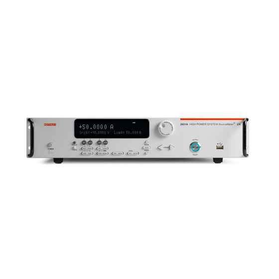
Operating: 0° C to 50° C, 70% relative humidity up to 35° C. Derate 3% relative humidity/° C, 35° C to 50° C Storage: -25° C to 65° C Front and rear panel operation Front panel The front panel of the Model 2651A is shown below. The descriptions of the front-panel controls follow the figure. - Page 24 MENU EXIT ENTER 1. Special keys and power switch Power switch. The in position turns the Model 2651A on (I); the out position turns it off (O). POWER Toggles between the various source-measure displays and the user message mode. DISPLAY Use to configure a function or operation.
- Page 25 Model 2651A High Power System SourceMeter® Instrument Reference Manual Section 2: General operation 2. Setup, performance control, special operation, and numbers Source-measure setup Selects the source function (V or A) and places the cursor in the source field for editing.
- Page 26 Section 2: General operation Model 2651A High Power System SourceMeter® Instrument Reference Manual 3. Range keys Selects the next higher source or measure range. Enables or disables source or measure autorange. Selects the next lower source or measure range. In addition to selecting range functions, the up and down range keys change the format for non-range numbers (as an example, when editing the limit value).
-
Page 27: Rear Panel
Source or measure autorange is selected AUTO: * (asterisk): Readings are being stored in the buffer Rear panel The rear panel of Model 2651A is shown below. The descriptions of the rear-panel components follow the figure. Figure 2: Rear panel Model 2651A LINE FUSE SLOWBLOW 5.0 A, 250 V... - Page 28 (provided), or a normal CAT-5 straight-through cable (not provided) can be used. 6. TSP-link Expansion interface that allows a Model 2651A and other TSP-enabled instruments to trigger and communicate with each other. Use a category 5e or higher LAN crossover cable (Keithley Instruments part number CA-180-3A).
-
Page 29: Cooling Vents
Section 2: General operation Cooling vents The Model 2651A has top and side intake vents and a rear exhaust vent. Either the top or both side intake vents, as well as the rear exhaust vent, must be unobstructed to properly dissipate heat. Do not place a container of liquid (water or coffee for instance) on the top cover. -
Page 30: Turning Your Instrument On And Off
Follow the procedure below to connect the Model 2651A to line power and turn on the instrument. The Model 2651A operates from a line voltage of 100 V to 240 V at a frequency of 50 Hz or 60 Hz. -
Page 31: System Identification
Model 2651A High Power System SourceMeter® Instrument Reference Manual Section 2: General operation To configure the line frequency from the front panel: 1. Press the MENU key, then turn the navigation wheel to select LINE-FREQ, and then press the ENTER key. -
Page 32: Beeper
Section 2: General operation Model 2651A High Power System SourceMeter® Instrument Reference Manual Beeper With the beeper enabled, a beep will be issued to acknowledge the following actions: • A short beep, emulating a key click, is issued when a front-panel key is pressed. -
Page 33: Basic Operation
Model 2651A High Power System SourceMeter® Instrument Reference Manual Section 2: General operation Basic operation Operation overview Quick Tip Before you begin any of the following front panel procedures, make sure that you exit out of the menu structure. Press the EXIT (LOCAL) key as needed to back out of a menu. - Page 34 When sourcing voltage, the Model 2651A can be set to limit current or power. Conversely, when sourcing current, the Model 2651A can be set to limit voltage or power. The Model 2651A output will not exceed the compliance limit. The maximum compliance limit is the same as the maximum values listed in the following table.
- Page 35 Model 2651A High Power System SourceMeter® Instrument Reference Manual Section 2: General operation Maximum compliance values for Model 2651A Source range Maximum compliance value 100 mV 20 A (50 A pulse) 20 A (50 A pulse) 10 V 20 A (50 A pulse)
- Page 36 = not in compliance). Basic circuit configurations The fundamental source-measure configurations for the Model 2651A are shown in the figure below. When sourcing voltage, you can measure current or voltage (configuration A). When sourcing current, you can measure voltage or current (configuration B). See...
-
Page 37: Menu Overview
B: Source I Menu overview Menu navigation To navigate through the menus and submenus, the Model 2651A must not be in edit mode (the EDIT indicator is not illuminated). Selecting menu items To navigate the Main and Configuration menus, use the editing keys as follows: •... - Page 38 Section 2: General operation Model 2651A High Power System SourceMeter® Instrument Reference Manual Main menu The main menu's structure is summarized in the following figure. For directions on navigating the menu, see Menu navigation (on page 2-15). For other menu items, see Configuration menus page 2-19).
- Page 39 Model 2651A High Power System SourceMeter® Instrument Reference Manual Section 2: General operation The following table contains descriptions of the main menu items, as well as cross-references to related information. To access a menu item, press the MENU key, turn the navigation wheel...
- Page 40 Section 2: General operation Model 2651A High Power System SourceMeter® Instrument Reference Manual Menu selection Description For more information, see: LINE-FREQ Configures the line frequency General operation page 2-1) - 50Hz Set the line frequency to 50 Hz - 60Hz...
- Page 41 Model 2651A High Power System SourceMeter® Instrument Reference Manual Section 2: General operation Configuration menus The configuration menu structure is summarized in the following figure. For directions on navigating the menu, see Menu navigation (on page 2-15). For other menu items, see...
- Page 42 Section 2: General operation Model 2651A High Power System SourceMeter® Instrument Reference Manual The following table contains descriptions of the configuration menus, as well as cross-references to related information. To select a menu, press the CONFIG key and then the front-panel key associated with the desired menu (see the description column in the following table).
- Page 43 Setting source and compliance values When the Model 2651A is in the edit mode (EDIT indicator is on), the editing controls are used to set source and compliance values. Note that source autoranging will turn off when editing the source value.
-
Page 44: Operation Considerations
The following paragraphs discuss autozero and NPLC caching. Autozero The integrating ADC of the Model 2651A uses a ratiometric A/D conversion technique. To ensure accuracy of readings, the instrument must periodically obtain fresh measurements of its internal ground and voltage reference. The time interval between needing to update these reference measurements is determined by the integration aperture being used for measurements. - Page 45 Model 2651A High Power System SourceMeter® Instrument Reference Manual Section 2: General operation This extra time can cause problems in sweeps and other test sequences in which measurement timing is critical. To avoid the extra time for the reference measurements in these situations, the OFF selection can be used to disable the automatic reference measurements.
-
Page 46: Basic Source-Measure Procedure
Hazardous voltages may be present on the output and guard terminals. To prevent electrical shock that could cause injury or death, NEVER make or break connections to the Model 2651A while the output is on. Power off the equipment from the front panel or disconnect the main power cord from the rear of the Model 2651A before handling cables connected to the outputs. - Page 47 When not measuring the source (such as when sourcing V but measuring I), measurement range selection can be done manually or automatically. When using manual ranging, use the lowest possible range for best accuracy. When autorange is enabled, the Model 2651A automatically goes to the most sensitive range to make the measurement.
- Page 48 Section 2: General operation Model 2651A High Power System SourceMeter® Instrument Reference Manual Basic source-measure commands Command Description Enable current measure autorange. smua.measure.autorangei = smua.AUTORANGE_ON Enable voltage measure autorange. smua.measure.autorangev = smua.AUTORANGE_ON Disable current measure autorange. smua.measure.autorangei = smua.AUTORANGE_OFF Disable voltage measure autorange.
-
Page 49: Triggering In Local Mode
Model 2651A High Power System SourceMeter® Instrument Reference Manual Section 2: General operation Source-measure programming example The following programming example illustrates the setup and command sequence of a basic source-measure procedure with the following parameters: • Source function and range: volts, autorange •... -
Page 50: Configuring Trigger Attributes In Local Mode
Section 2: General operation Model 2651A High Power System SourceMeter® Instrument Reference Manual The following figure shows the general sequence for measurement triggering. The basic sequence is as follows: • When the output is turned on, the programmed source value is immediately applied to the device under test (DUT). -
Page 51: Sink Operation And Interface
Model 2651A High Power System SourceMeter® Instrument Reference Manual Section 2: General operation INTERVAL: Sets the time interval between measurements (0 s to 999.999 s) when the count is greater than 1. DELAY: Sets the delay period between the trigger and the start of measurement (0 s to 999.999 s). -
Page 52: Configuring For Measure Only Tests Using The Mode Key
When using the I-Source as a sink, ALWAYS set V-Compliance to a level that is higher than the external voltage level. Failure to do so could result in excessive current flow into the Model 2651A (<102 mA) and incorrect measurements. See Compliance limit for details. - Page 53 Section 2: General operation CAUTION When using the Model 2651A as a voltmeter, V-compliance must be set higher than the voltage that is being measured. Failure to do this could result in excessive current flow into the Model 2651A (<100 A) and incorrect measurements.
- Page 54 Hazardous voltages may be present on the output and guard terminals. To prevent electrical shock that could cause injury or death, NEVER make or break connections to the Model 2651A while the output is on. Power off the equipment from the front panel or disconnect the main power cord from the rear of the Model 2651A before handling cables connected to the outputs.
- Page 55 Model 2651A High Power System SourceMeter® Instrument Reference Manual Section 2: General operation Figure 8: 2-wire resistance sensing Model 2651A Test Current (I) Input/Output HI LEAD Lead Resistance Resistances Under Test Input/Output LO LEAD I = Current sourced = Voltage measured = Voltage across resistor + (2 ×...
- Page 56 Section 2: General operation Model 2651A High Power System SourceMeter® Instrument Reference Manual Figure 9: 4-wire resistance sensing Model 2651A Test Current (I) Input/Output HI LEAD Sense Current (pA) LEAD 4-wire Sense HI Lead Resistance Resistances Under Test 4-wire Sense LO...
- Page 57 Model 2651A High Power System SourceMeter® Instrument Reference Manual Section 2: General operation Remote ohms command Use the smua.measure.r() function to obtain a resistance reading. The programming example below illustrates how to obtain a resistance reading from SMU A: reading = smua.measure.r()
- Page 58 Hazardous voltages may be present on the output and guard terminals. To prevent electrical shock that could cause injury or death, NEVER make or break connections to the Model 2651A while the output is on. Power off the equipment from the front panel or disconnect the main power cord from the rear of the Model 2651A before handling cables connected to the outputs.
-
Page 59: Contact Check Measurements
Model 2651A High Power System SourceMeter® Instrument Reference Manual Section 2: General operation Remote power command The programming example below illustrates how to obtain a power reading from smua: reading = smua.measure.p() See for more commands necessary to set up source and measure functions and also... - Page 60 Hazardous voltages may be present on the output and guard terminals. To prevent electrical shock that could cause injury or death, NEVER make or break connections to the Model 2651A while the output is on. Power off the equipment from the front panel or disconnect the main power cord from the rear of the Model 2651A before handling cables connected to the outputs.
-
Page 61: User Setup
Saving user setups You can save the present Model 2651A setup to internal nonvolatile memory or a USB flash drive. To save a user setup to nonvolatile memory: 1. Configure the Model 2651A for the desired operating modes to be saved. - Page 62 1. Configure the Model 2651A for the desired operating modes to be saved. 2. Insert the USB flash drive into the USB port on the front panel of the Model 2651A. 3. Press the MENU key, then select SETUP, then press the ENTER key.
- Page 63 -- Recall saved user setup from nonvolatile memory. setup.recall(1) Restoring the factory default setups Use one of the reset functions to return the Model 2651A to the original factory defaults: -- Restore all factory defaults of all nodes on the TSP-Link network. reset() -- Restore all factory defaults (note that -- you cannot use "*rst"...
-
Page 64: Dut Test Connections
Installation Category I only, with transients rated less than 1500 V peak. Do not connect the Model 2651A terminals to CAT II, CAT III, or CAT IV circuits. Connections of the input/output connectors to circuits higher than CAT I can cause damage to the equipment or expose the operator to hazardous voltages. -
Page 65: 2-Wire Local Sensing
NOTE Using the chassis as a ground point for signal connections to the Model 2651A chassis may result in higher or lower noise. The tie point to the chassis can help quiet measurements if the Model 2651A common-mode current is channeled to the chassis instead of the device. -
Page 66: 4-Wire Remote Sensing
When sourcing voltage in remote sense, make sure the sense leads are connected to the DUT. If a sense lead becomes disconnected, an erroneous voltage will be sensed, and the Model 2651A will increase the output voltage to compensate. You can use contact check to verify that the sense leads are connected. -
Page 67: Contact Check Connections
• Select V-MEAS > SENSE-MODE. 4. Select 2-WIRE or 4-WIRE as desired. * The Model 2651A sense mode can be accessed and set from either the V-SOURCE or the V-MEAS menu items. Remote programming sense selection The following table summarizes the commands to select the sense mode. See Programming commands for details on using these commands. -
Page 68: Multiple Smu Connections
Failure to consider the output-off state, source, and compliance levels may result in damage to the instrument or to the device under test. The figure below shows how to use the SMUs of two Model 2651A instruments to test a 3-terminal device, such as an N-channel JFET (see... - Page 69 Model 2651A High Power System SourceMeter® Instrument Reference Manual Section 2: General operation Figure 15: Two SMUs connected to a 3-terminal device (local sensing) Model 2651A (master) SENSE/GUARD OUTPUT G G G 40V, 50A MAX. Equivalent N-Channel JFET (subordinate) (master)
-
Page 70: Combining Smu Outputs
® When combining the outputs of two Model 2651A High Power System SourceMeter Instruments, restrict operation to pulse only for all operating areas (both the standard and the extended operating areas). - Page 71 Model 2651A High Power System SourceMeter® Instrument Reference Manual Section 2: General operation Pulse region specification Region Region Maximum Maximum (quadrant maximum pulse width duty cycle diagram) 30 A at 10 V 1 ms 20 A at 20 V 1.5 ms 10 A at 40 V 1.5 ms...
- Page 72 Section 2: General operation Model 2651A High Power System SourceMeter® Instrument Reference Manual SourceMeter instrument configuration Guidelines Source voltage using series SMUs Maximum Pulsed Signal Levels for Model 2651A: 80 V with 45 A compliance SMU 1 configuration: Output-off mode: smuX.source.offmode = smuX.OUTPUT_NORMAL...
- Page 73 To prevent electrical shock that could cause injury or death, NEVER use the Model 2651A in a test circuit that may contain hazardous voltages without a properly installed and configured safety shield.
- Page 74 Model 2651A High Power System SourceMeter® Instrument Reference Manual Higher pulse voltage can be output by connecting two (and only two) Model 2651A instrument's channels in series. When combining two SMU channels, make sure both SMUs have the same model number.
-
Page 75: Guarding And Shielding
Model 2651A High Power System SourceMeter® Instrument Reference Manual Section 2: General operation The figure below illustrates the connection scheme of two Model 2651A instruments connected in parallel. Two Model 2651A can output up to 100 A at 36 V (see... - Page 76 A safety shield must be used whenever hazardous voltages (>30 V RMS, 42 V peak) will be present in the test circuit. To prevent electrical shock that could cause injury or death, NEVER use the Model 2651A in a test circuit that may contain hazardous voltages without a properly installed and configured safety shield.
- Page 77 (on page 2-57) later in this section for important safety information on the use of a metal or nonmetallic enclosure. Model 2651A safety shield The maximum output voltage for a Model 2651A channel is 40 V, which is considered a nonhazardous level. However, using two Model 2651A voltage sources in a series configuration or floating a SMU (on page 2-58) can cause test circuit voltage to exceed 42 V.
- Page 78 Section 2: General operation Model 2651A High Power System SourceMeter® Instrument Reference Manual Using shielding and guarding together The following figures show connections for a test system that uses a noise shield, a safety shield, and guarding. The guard shields are connected to the driven guard (G) of the SMU. The noise shield is connected to SMU LO.
-
Page 79: Test Fixture
Test fixture The Model 2651A digital I/O port provides an output enable line for use with a test fixture switch. When properly used, the output of the Model 2651A will turn off when the lid of the test fixture is opened. -
Page 80: Floating A Smu
For the test circuit shown below, the Model 2651A must float off chassis earth ground. As shown, SMU LO of the Model 2651A is floating +10 V above chassis earth ground. If SMU LO of the Model 2651A was instead connected to chassis ground, the external voltage source would be shorted through chassis ground. -
Page 81: Output-Off States
The output-off mode can be used to place the Model 2651A in a known, safe, non-interactive state during idle periods, for example, when changing devices. A Model 2651A SMU can be in one of three output-off modes: Normal, high-impedance, or zero. - Page 82 • Measurements are performed and displayed. The Model 2651A can be used as an I-Meter when it is in ZERO output-off mode because it will output 0 V, but measure current. Selecting the output-off mode...
- Page 83 Section 2: General operation Output-off function This setting is used only when the when output is turned off and the Model 2651A is in NORMAL output-off mode (smuX.source.offmode = smuX.OUTPUT_NORMAL). When the Model 2651A is in NORMAL output-off mode, you can set the output-off function to CURRENT or VOLTAGE through the CONFIG menu on the front panel, or by using the smuX.source.offfunc attribute from a remote interface.
- Page 84 Output-off limits You can set output-off limits for the current and voltage output-off functions using the CONFIG menu on the Model 2651A front panel, or by using the smuX.source.offlimitY attribute from a remote interface. This setting controls only output-off limits.
-
Page 85: Usb Storage Overview
Connecting the USB flash drive The Model 2651A supports flash drives that comply with USB 1.0 and 2.0 standards. You can save data to the USB flash drive from the front panel, or you can create a script to save data to the USB flash drive. -
Page 86: File System Navigation
Section 2: General operation Model 2651A High Power System SourceMeter® Instrument Reference Manual Figure 25: USB port Meter ® File system navigation Use supported commands from the Lua fs library to navigate and list available files on a flash drive. -
Page 87: Error And Status Messages
This usually happens when a change such as selecting a different range occurs. Available ranges The following table lists the available source and measurement ranges for the Keithley Instruments ® Model 2651A High Power System SourceMeter Instrument. -
Page 88: Maximum Source Values And Readings
(on page 7-196). Ranging limitations • Model 2651A: The maximum output power and source/sink limit for the Model 2651A is 202 W per channel (maximum). With the 40 V (V-Source) range selected, the highest current measurement range is 5 A. Refer to... -
Page 89: Manual Ranging
Source autoranging will turn off when editing the source value. Low range limits The low range limit sets the lowest range the Model 2651A will use when autoranging is enabled. This feature is useful for minimizing autorange settling times when numerous range changes are involved. -
Page 90: Range Considerations
Section 2: General operation Model 2651A High Power System SourceMeter® Instrument Reference Manual Range considerations The source range and measure range settings can interact depending on the source function. Additionally, the output state (on/off) can affect how the range is set. The following table describes these interactions: If... -
Page 91: Range Programming
Model 2651A High Power System SourceMeter® Instrument Reference Manual Section 2: General operation Range programming Range commands The following tables summarize commands necessary to control measure and source ranges. See Remote commands (on page 5-1) for more details about these commands. - Page 92 Section 2: General operation Model 2651A High Power System SourceMeter® Instrument Reference Manual Source range commands* Commands Description Enable current source smua.source.autorangei = smua.AUTORANGE_ON autorange. Disable current source smua.source.autorangei = smua.AUTORANGE_OFF autorange. Enable voltage source smua.source.autorangev = smua.AUTORANGE_ON autorange. Disable voltage source smua.source.autorangev = smua.AUTORANGE_OFF...
-
Page 93: Digits
Model 2651A High Power System SourceMeter® Instrument Reference Manual Section 2: General operation Digits The display resolution of the measured reading depends upon the DIGITS setting. The DIGITS setting selects display resolution for all measurement functions. The DIGITS setting has no effect on the remote reading format. The number of displayed digits does not affect accuracy or speed. -
Page 94: Setting Speed
Section 2: General operation Model 2651A High Power System SourceMeter® Instrument Reference Manual Setting speed Speed is set from the SPEED configuration menu and is structured as follows. Front-panel speed configuration Press SPEED (or use the CONFIG menu) to display the following menu items: •... -
Page 95: Communications Interfaces
LAN interfaces. The Model 2651A can only be controlled from one remote interface at a time. The unit will remote to the first interface on which it receives a message. It will ignore the other interface until the unit is taken back to local operation. -
Page 96: Lan Communications
Local area network (LAN) communications provide the flexibility to build scalable and functional test or data acquisition systems with a large degree of flexibility. The Model 2651A is a Class C LXI- compliant instrument that supports TCP/IP and complies with IEEE std 802.3 (Ethernet). There is one LAN port (located on the back of the instrument) that supports full connectivity on a 10 Mbps or 100 Mbps network. - Page 97 When the LED is: The network: is NOT connected is connected Blinking has traffic traversing the port Using the LAN with remote operations The following table lists the Model 2651A remote interface's available protocols: LAN protocols Port number Protocol Telnet 1024 VXI-11...
-
Page 98: Gpib Operation
Section 2: General operation Model 2651A High Power System SourceMeter® Instrument Reference Manual Raw socket: Raw socket is a basic Ethernet connection that communicates similarly to RS-232 without explicit message boundaries. The instrument will always terminate messages with a line feed, but because binary data may include bytes that resemble line feed characters, it may be difficult to distinguish between data and line feed characters. - Page 99 Contact Keithley Instruments for shielded cables. To connect the Model 2651A to the IEEE-488 bus, line up the cable connector with the connector located on the rear panel. Install and tighten the screws securely, making sure not to overtighten them (the following figure shows the location of the connections).
-
Page 100: General Bus Commands
Primary address The Model 2651A ships from the factory with a GPIB primary address of 26. If the GPIB interface is enabled, it momentarily displays the primary address on power-up. You can set the address to a value from 0 to 30, but do not assign the same address to another device or to a controller that is on the same GPIB bus (controller addresses are usually 0 or 21). - Page 101 SPE, SPD Serial polls the Model 2651A. The remote enable command (REN) is sent to the Model 2651A by the controller to set up the instrument for remote operation. Generally, the instrument should be placed in the remote mode before you attempt to program it over the bus. Setting REN true does not place the instrument in the remote state.
-
Page 102: Front-Panel Gpib Operation
The group execute trigger command (GET) is a GPIB trigger that is used to trigger the instrument to take readings from a remote interface. SPE, SPD Use the serial polling sequence to obtain the Model 2651A serial poll byte. The serial poll byte contains important information about internal functions (see Status Model (on page E-1)). -
Page 103: Rs-232 Interface Operation
IFC (Interface Clear) command. LSTN This indicator is on when the Model 2651A is in the listener active state, which is activated by addressing the instrument to listen with the correct listen command. LSTN is off when the unit is in the listener idle state. - Page 104 Sending data using the serial.write() function does not append a terminator. Be sure to append the appropriate terminator to the message before sending it. Baud rate The baud rate is the rate at which the Model 2651A and the programming terminal communicate. Select one of the following available rates: •...
- Page 105 The RS-232 interface provides two control lines (RTS and CTS) for this purpose (see the following figure and table). When the Model 2651A is ready to send (RTS) data, it will transmit when it receives the clear to send (CTS) signal from the computer.
- Page 106 Section 2: General operation Model 2651A High Power System SourceMeter® Instrument Reference Manual Figure 31: RS-232 interface connector RS-232 5 4 3 2 1 9 8 7 6 Rear Panel Connector RS-232 connector pinout Pin number Description Not used TXD, transmit data...
- Page 107 DSR, data set ready RTS, request to send CTS, clear to send RI, ring indicator * The Model 2651A does not use all RS-232 signals. See the topic Flow control and signal handshaking (on page 2-83). 2651A-901-01 Rev. A / March 2011...
-
Page 108: Functions And Features
Selecting a range that cannot accommodate the rel value does not cause an overflow condition, but it also does not increase the maximum allowable input for that range. For example, on the 1 A range, the Model 2651A still overflows for a >1.02 A input. NOTE When rel is enabled, the REL indicator turns on. -
Page 109: Remote Rel Programming
Section 3: Functions and features Model 2651A High Power System SourceMeter® Instrument Reference Manual Defining a rel value A unique rel value can be established for the selected measurement function. To establish a unique rel value from the front panel: 1. -
Page 110: Filters
(from 1 to 100). Filter types The Model 2651A has three filter types. These three filter types are broken down into two averaging filters and one median filter. The two averaging filters are repeating and moving (see figure below). For the repeat filter (which is the power-on default), the stack (filter count) is filled, and the conversions are averaged to yield a reading. -
Page 111: Front Panel Filter Control
Section 3: Functions and features Model 2651A High Power System SourceMeter® Instrument Reference Manual The moving average filter uses a first-in, first-out stack. When the stack (filter count) becomes full, the measurement conversions are averaged, yielding a reading. For each subsequent conversion placed into the stack, the oldest conversion is discarded. - Page 112 Model 2651A High Power System SourceMeter® Instrument Reference Manual Section 3: Functions and features To configure the filter: 1. Press the CONFIG key and then the FILTER key. 2. Select TYPE, and then select filter type: AVERAGE or MEDIAN. •...
-
Page 113: Reading Buffers
You can use the dedicated reading buffers to acquire readings, or you can use the smuX.makebuffer() function to create dynamic reading buffers. Each dedicated reading buffer in the Model 2651A can store over 60,000 readings with the timestamps and source values options enabled. Disable the timestamps and source values options to store over 140,000 readings internally. - Page 114 Model 2651A High Power System SourceMeter® Instrument Reference Manual Section 3: Functions and features NOTE You must clear the reading buffer before you enable or disable the source value or the timestamp options. 5. Configure the reading buffer's timestamp elements: a.
- Page 115 Section 3: Functions and features Model 2651A High Power System SourceMeter® Instrument Reference Manual To configure the instrument to append or overwrite measurements the next time data is acquired: 1. Complete the steps from Saving reading buffers (on page 3-8).
- Page 116 Model 2651A High Power System SourceMeter® Instrument Reference Manual Section 3: Functions and features To save the reading buffer data: 1. From the front panel, press the STORE key, and then select SAVE. 2. Select INTERNAL to save to internal nonvolatile memory.
-
Page 117: Remote Reading Buffer Programming
Section 3: Functions and features Model 2651A High Power System SourceMeter® Instrument Reference Manual Timestamp If the timestamp is enabled, the first source-measure reading stored in the buffer (#0000001) is timestamped at 0.000 seconds. Subsequent readings are timestamped relative to when the first measurement was made. - Page 118 Model 2651A High Power System SourceMeter® Instrument Reference Manual Section 3: Functions and features Reading buffer commands The following table summarizes commands associated with the reading buffers. See Remote commands (on page 5-1) for detailed reading buffer command information. Reading buffer commands...
- Page 119 Section 3: Functions and features Model 2651A High Power System SourceMeter® Instrument Reference Manual NOTE Before changing the collectsourcevalues, collecttimestamps, or timestampresolution attributes, you must clear the buffer using the smua.nvbuffer1.clear() or smua.nvbuffer2.clear() command. Buffer storage control attributes: Describes buffer storage attributes...
- Page 120 Model 2651A High Power System SourceMeter® Instrument Reference Manual Section 3: Functions and features Buffer read-only attributes The following table contains buffer read-only attributes. Buffer read-only attributes: Read-only attributes used to access buffer parameters Storage attribute Description The timestamp of when the reading at rb[1] was stored, in seconds from basetimestamp midnight January 1, 1970 GMT.
- Page 121 Section 3: Functions and features Model 2651A High Power System SourceMeter® Instrument Reference Manual Statistic attributes Use the smua.buffer.getstats() function to access the reading buffer data statistics. The table below displays the attributes that you can use to access the reading buffer data.
- Page 122 Model 2651A High Power System SourceMeter® Instrument Reference Manual Section 3: Functions and features Example: The following programming example illustrates how to output mean and standard deviation statistics from buffer 1: statistics = smua.buffer.getstats(smua.nvbuffer1) print(statistics.mean, statistics.stddev) Reading buffer attributes Use the reading buffer attributes to access the reading buffer data. The table below displays the attributes that you can use to access the reading buffer data.
- Page 123 Section 3: Functions and features Model 2651A High Power System SourceMeter® Instrument Reference Manual Buffer status The buffer reading status attribute can include the status information as a numeric value; see the following table for values. For example, to access status information for second element, use the following command: stat_info = smua.nvbuffer1.statuses[2]...
- Page 124 The following programming example illustrates how to store data using dedicated reading buffer 1 for channel A. In the example, the Model 2651A loops for voltages from 0.01 V to 1 V with 0.01 V steps (essentially performing a staircase sweep), stores 100 current readings and source values in buffer 1, and then recalls all 100 readings and source values.
- Page 125 The programming example below shows a script for storing both current and voltage readings using buffer 1 for current and buffer 2 for voltage readings. The Model 2651A stores 100 current and voltage readings and then recalls all 100 sets of readings.
-
Page 126: Sweep Operation
Section 3: Functions and features Dynamically allocated buffer example The programming example below illustrates how to store data to an allocated buffer called mybuffer. The Model 2651A stores 100 current readings in mybuffer and then recalls all the readings. -- Restore Model 2651A defaults. -
Page 127: Sweep Characteristics
DC and pulsed list sweeps (C): The list sweep allows you to program arbitrary sweep steps anywhere within the output voltage or current range of the Model 2651A. This portion of the figure (C) shows a list sweep with arbitrary steps and a pulsed list sweep. Pulsed list sweeps function the same way that DC list sweeps function, except pulsed list sweeps return to the idle level between pulses. - Page 128 Model 2651A High Power System SourceMeter® Instrument Reference Manual Section 3: Functions and features Linear staircase sweeps As shown below, this sweep type steps from a start voltage or current value to an ending (stop) value. A measurement is made at each point after source and measurement settling time.
- Page 129 Section 3: Functions and features Model 2651A High Power System SourceMeter® Instrument Reference Manual Example: -- Sweep from 0 to 10 V in 1 V steps. smua.trigger.source.linearv(0, 10, 11) -- Enable the source action. smua.trigger.source.action = smua.ENABLE For more information, see smuX.trigger.source.linearY() (on page 7-243).
- Page 130 Model 2651A High Power System SourceMeter® Instrument Reference Manual Section 3: Functions and features Figure 36: Increasing logarithmic sweep Source level 2 to 8 with A = 0 2 to 8 with A = 1.8 2 to 8 with A = 8.5...
- Page 131 Section 3: Functions and features Model 2651A High Power System SourceMeter® Instrument Reference Manual Solving for k and b provides the following formulas: k = V start log10(V - A) - log10(V - A) start b = 10 Where: = The source value at the end point...
- Page 132 Model 2651A High Power System SourceMeter® Instrument Reference Manual Section 3: Functions and features In this example: A = 0, V = 1, V = 10, N = 5 start Using the formula above, k = 1 Step size (b) for the sweep in the above figure is calculated as follows: log10(stop-0) log10(start-0) ⎛...
- Page 133 Section 3: Functions and features Model 2651A High Power System SourceMeter® Instrument Reference Manual List sweeps Use a list sweep to configure a sweep with arbitrary steps. A measurement is made at each point after source and measurement settling time.
- Page 134 Model 2651A High Power System SourceMeter® Instrument Reference Manual Section 3: Functions and features Timers must be used to configure the pulse width and period. Refer to Using timers to perform pulse mode sweeps (on page 3-45) for details. The pulse width is managed by controlling the duration between the source stimulus event and the end pulse stimulus event.
- Page 135 Pulse sweeps can be performed outside of the standard operating area by setting the appropriate compliance level. Review the specifications for the Model 2651A to determine the maximum current and voltage values available in pulse mode. When pulsing in the extended operating area (EOA), the source-measure unit (SMU) will force the pulse to end early if the pulse width exceeds the maximum value.
-
Page 136: Configuring And Running Sweeps
Model 2651A High Power System SourceMeter® Instrument Reference Manual Section 3: Functions and features Configuring and running sweeps Configuring compliance limits remotely Voltage and current limits can be configured using the smuX.trigger.source.limitY attribute, which sets the sweep source limits. For example, to set the smua sweep limit to 10 V, execute: smua.trigger.source.limitv = 10... -
Page 137: Sweeping Using Factory Scripts
Section 3: Functions and features Model 2651A High Power System SourceMeter® Instrument Reference Manual Initiating and running sweeps To run a sweep, you must configure the number of sweep points to output and the number of sweeps to perform. Use the trigger count to set the number of sweep points to output. Use the arm count to set the number of times to perform the sweep. - Page 138 Model 2651A High Power System SourceMeter® Instrument Reference Manual Section 3: Functions and features Sweep example parameters Sweep type Parameters for sweep examples Linear staircase sweep Start current: 1 mA Stop current: 10 mA # points: 10 Settling time: 0.1...
-
Page 139: Triggering
Section 3: Functions and features Model 2651A High Power System SourceMeter® Instrument Reference Manual Pulse sweep examples The programming example below illustrates a pulse sweep. 1. Configure source functions. -- Restore Model 2651A defaults. Restores defaults and set the compliance to smua.reset() - Page 140 External triggers are possible using digital I/O, TSP-Link synchronization lines, LAN, command interface, and the manual trigger (the TRIG key). The following figure graphically represents all the trigger objects of the Model 2651A instrument. Figure 42: Triggering overview Manual trigger...
-
Page 141: Using The Remote Trigger Model
Using the remote trigger model The source-measure unit (SMU) in the Model 2651A has a remote trigger model that supports a wide range of triggering features for source sweeps, triggered measurements, and pulse actions. - Page 142 Model 2651A High Power System SourceMeter® Instrument Reference Manual Section 3: Functions and features Figure 43: Remote trigger model: Normal (synchronous) mode Idle Idle event Configure and enable sweep source or sweep smuX.trigger.IDLE_EVENT_ID measure actions, then send: smuX.trigger.initiate() Arm layer Sweeping event smuX.trigger.SWEEPING_EVENT_ID...
- Page 143 Section 3: Functions and features Model 2651A High Power System SourceMeter® Instrument Reference Manual Figure 44: Remote trigger model: Asynchronous mode Idle Idle event Configure and enable sweep source or sweep smuX.trigger.IDLE_EVENT_ID measure actions, then send: smuX.trigger.initiate() Arm layer Sweeping event smuX.trigger.SWEEPING_EVENT_ID...
- Page 144 Model 2651A High Power System SourceMeter® Instrument Reference Manual Section 3: Functions and features When the smuX.trigger.measure.action attribute is set to smuX.DISABLE or smuX.ENABLE, the trigger model will operate in synchronous measurement mode. When it is set to smuX.ASYNC, it will operate in asynchronous mode.
- Page 145 Section 3: Functions and features Model 2651A High Power System SourceMeter® Instrument Reference Manual The source-measure unit (SMU) can be configured to perform any or all available measurements during a sweep using the smua.trigger.measure.Y() function. To enable the measure action for a simple synchronous sweep, set the smua.trigger.measure.action attribute to...
-
Page 146: Smu Event Detectors
Model 2651A High Power System SourceMeter® Instrument Reference Manual Section 3: Functions and features SMU event detectors As shown in the Using the remote trigger model (on page 3-34) topic, the source-measure unit (SMU) has multiple event detectors (see the table below) in order to control the timing of various actions. -
Page 147: Using Trigger Events To Start Actions On Trigger Objects
Section 3: Functions and features Model 2651A High Power System SourceMeter® Instrument Reference Manual The programming example below illustrates how to configure a 10-point linear voltage sweep on SMU A, where each step is triggered by the front-panel TRIG key: -- Configure a 10-point source voltage sweep. -
Page 148: Digital I/O Port And Tsp-Link Synchronization Lines
Digital I/O port and TSP-Link synchronization lines The Model 2651A has two sets of hardware lines that can be used for triggering: 14 digital I/O lines ®... - Page 149 Specifies the pulse width of the output trigger signal when the hardware line is asserted. Trigger configuration on hardware lines The Model 2651A can be configured to send digital signals to trigger external instruments. Linking these output triggers to the completion of certain source-measure actions enables hardware handshaking.
-
Page 150: Timers
A timer is a trigger object that performs a delay when triggered. Timers can be used to create delays and to start measurements and step the source value at timed intervals. When a delay expires the timer generates a trigger event. The Model 2651A has 8 independent timers. Timer attributes Each timer has four attributes that can be configured. - Page 151 Section 3: Functions and features Model 2651A High Power System SourceMeter® Instrument Reference Manual Timer delays Timers can be configured to perform the same delay each time or configured with a delay list that allows the timer to sequence through an array of delay values. All delay values are specified in seconds.
- Page 152 Model 2651A High Power System SourceMeter® Instrument Reference Manual Section 3: Functions and features Figure 48: Using a timer for an SDM cycle Stimulus input: smua.trigger.measure.stimulus Legend: = Trigger object Timer SMU A = Trigger events = External output trigger...
- Page 153 Section 3: Functions and features Model 2651A High Power System SourceMeter® Instrument Reference Manual SMU A • Configure the source action to start immediately by setting the stimulus input of the source event detector to 0. • Set the end pulse action to SOURCE_IDLE.
- Page 154 Model 2651A High Power System SourceMeter® Instrument Reference Manual Section 3: Functions and features Pulse train example: The programming example below illustrates how to use two timers: One to control the pulse period, a second to control the pulse width. The example configures the timers and SMU as follows: Timer 1: Pulse period timer •...
- Page 155 Section 3: Functions and features Model 2651A High Power System SourceMeter® Instrument Reference Manual -- Generate a 10-point pulse train where each pulse has a width of 600 -- microseconds and a pulse period of 5 milliseconds. -- Alias the trigger timers to use for pulse width and period.
-
Page 156: Event Blenders
Model 2651A High Power System SourceMeter® Instrument Reference Manual Section 3: Functions and features Figure 51: Pulse train triggering Trigger event: trigger.timer[1].EVENT_ID Stimulus input: trigger.timer[1].stimulus ulus Timer #1 Timer #2 (pulse period) (pulse width) Stimulus input: smua.trigger.source.stimulus Trigger event: trigger.timer[2].EVENT_ID Stimulus input: trigger.timer[2].stimulus... -
Page 157: Lan Triggering Overview
The stateless event flag is a bit in the LXI trigger packet that indicates if the hardware value should be ignored. If set, the Model 2651A ignores the hardware value of the packet and generates a trigger event. The Model 2651A always sets the stateless flag for outgoing LXI trigger packets. If the stateless event flag is not set, then the hardware value indicates the state of the signal. - Page 158 LAN0 and lan.trigger[8] corresponds to LXI trigger event LAN7. Generating LXI trigger packets The Model 2651A can be configured to output an LXI trigger packet to other LXI instruments. To generate LXI trigger packets, you must first call the lan.trigger[N].connect() function. Select the event that triggers the outgoing LXI trigger packet by assigning the specific event ID to the LAN stimulus input.
-
Page 159: Command Interface Triggering
Command interface triggering does not generate action overruns. The triggers are processed in the order that they are received in the Model 2651A input queue. The Model 2651A does not process incoming commands while a script is running. Input triggers that are not processed can cause an overflow in the input queue. - Page 160 Section 3: Functions and features Detecting trigger events using the wait() function All of the Model 2651A trigger objects (except for SMUs) have built-in event detectors that monitor for trigger events. The event detector only monitors events generated by that object and cannot be configured to monitor events generated by any other trigger object.
- Page 161 Section 3: Functions and features Model 2651A High Power System SourceMeter® Instrument Reference Manual Using the release() function of the hardware lines Use the release() function to allow the hardware line to output another external trigger when the pulse width is set to 0.
- Page 162 The programming example below illustrates how to configure digital I/O line 2 as an input trigger and digital I/O line 14 as an output trigger. It commands the Model 2651A to wait for an external input trigger on digital I/O line 2. If a trigger event occurs, the Model 2651A outputs an external trigger on digital I/O line 14.
-
Page 163: Hardware Trigger Modes
Hardware trigger modes Different hardware trigger modes can be used for digital I/O and TSP-Link synchronization. Use hardware triggers to integrate Keithley instruments and non-Keithley instruments in a test system. ® The Model 2651A supports 14 digital I/O lines and three TSP-Link synchronization lines that can be used for input or output triggering. - Page 164 Use the rising edge master (RisingM) trigger mode (see the figure titled "RisingM output trigger") to synchronize with non-Keithley instruments that require a high pulse. Input trigger detection is not available in this trigger mode. You can use the RisingM trigger mode to generate rising edge pulses.
- Page 165 Section 3: Functions and features Model 2651A High Power System SourceMeter® Instrument Reference Manual Output characteristics: • Configured trigger events, as well as the digio.trigger[N].assert() and tsplink.trigger[N].assert() commands, cause the physical line state to float high during the trigger pulse duration.
- Page 166 Model 2651A High Power System SourceMeter® Instrument Reference Manual Section 3: Functions and features Output characteristics: • In addition to trigger events from other trigger objects, the digio.trigger[N].assert() and tsplink.trigger[N].assert() commands generate a low pulse that is similar to the falling edge trigger mode.
-
Page 167: Understanding Synchronous Triggering Modes
In this mode, the output trigger consists of a low pulse. All non-Keithley instruments attached to the synchronization line in a trigger mode equivalent to SynchronousA must latch the line low during the pulse duration. - Page 168 Model 2651A High Power System SourceMeter® Instrument Reference Manual Section 3: Functions and features NOTE Use the SynchronousM trigger mode to receive notification when the triggered action on all nodes is complete. Input characteristics: • All rising edges are input triggers.
- Page 169 Section 3: Functions and features Model 2651A High Power System SourceMeter® Instrument Reference Manual Figure 60: SynchronousM output trigger External Drive Internal Drive Physical Line State Event Stimulus Event Action Overrun Pulse Duration Output Trigger Synchronous acceptor trigger mode (SynchronousA) Use the synchronous acceptor trigger mode (SynchronousA) in conjunction with the SynchronousM trigger mode.
- Page 170 Output Trigger Synchronous trigger mode The synchronous trigger mode is a combination of SynchronousA and SynchronousM trigger modes. Use the Synchronous trigger mode for compatibility with older Keithley Instruments products. NOTE Keithley Instruments recommends using SynchronousA and SynchronousM modes only.
- Page 171 Section 3: Functions and features Model 2651A High Power System SourceMeter® Instrument Reference Manual Figure 63: Synchronous input trigger External Drive Internal Drive Physical Line State Event Stimulus Event Action Overrun Input Trigger Output characteristics: • In addition to trigger events from other trigger objects, the digio.trigger[N].assert() and tsplink.trigger[N].assert() functions generate a low pulse for the programmed pulse...
-
Page 172: High-Capacitance Mode
In normal operation, the SMU in the Model 2651A can drive capacitive loads as large as 10 nF. In high-capacitance mode, the SMU can drive a maximum of 50 μF of capacitance. - Page 173 50 μF. The Model 2651A is specified for operating into high Q inductances up to 3 μH on all ranges of voltage and current.
- Page 174 Model 2651A High Power System SourceMeter® Instrument Reference Manual Section 3: Functions and features Adjusting the voltage source When driving large capacitive loads with high-capacitance mode enabled, the response time may be lengthened by the current limit. For example, see the table titled "Current measure and source settling (on page 3-66) topic.
-
Page 175: Enabling High-Capacitance Mode
Section 3: Functions and features Model 2651A High Power System SourceMeter® Instrument Reference Manual Enabling high-capacitance mode Before enabling high-capacitance mode, note the following: • It is important to read the previous section to understand the impact of high-capacitance mode. - Page 176 Model 2651A High Power System SourceMeter® Instrument Reference Manual Section 3: Functions and features Measuring current The following inputs are required to test leakage using the factory leakage script, as shown in the script example below. • SMU: Sets the Model 2651A source-measure unit to use •...
-
Page 177: Display Operations
Section 3: Functions and features Model 2651A High Power System SourceMeter® Instrument Reference Manual Figure 65: Enabling high-capacitance mode levelv = 5 limit = 1 A levelv = 0 Display operations Display functions and attributes The display functions and attributes are used to perform the display operations covered in this section. -
Page 178: Display Features
Model 2651A High Power System SourceMeter® Instrument Reference Manual Section 3: Functions and features Cross-referencing functions and attributes to section topics Function or attribute Section topic Clearing the display (on page 3-73) display.clear() Indicators (on page 3-78) display.getannunciators() Cursor position (on page 3-73) display.getcursor() -
Page 179: Display Messages
The display of the Model 2651A can be used to display user-defined messages. For example, while a test is running, the following message can be displayed on the Model 2651A. - Page 180 Model 2651A High Power System SourceMeter® Instrument Reference Manual Section 3: Functions and features Clearing the display When sending a command to display a message, a previously defined user message is not cleared. The new message starts at the end of the old message on that line. It is good practice to routinely clear the display before defining a new message.
- Page 181 Section 3: Functions and features Model 2651A High Power System SourceMeter® Instrument Reference Manual The following programming example illustrates how to position the cursor on row 2, column 1, and then read the cursor position: display.setcursor(2, 1) row, column = display.getcursor() print(row, column) Output: 2.00000e+00 1.00000e+00...
- Page 182 Model 2651A High Power System SourceMeter® Instrument Reference Manual Section 3: Functions and features The following programming example illustrates how to use the $$ character code to display the message “You owe me $8” on the top line: display.clear() display.setcursor(1, 1) display.settext("You owe me $$8")
-
Page 183: Input Prompting
Section 3: Functions and features Model 2651A High Power System SourceMeter® Instrument Reference Manual Input prompting Display messaging can be used along with front panel controls to make a user script interactive. In an interactive script, input prompts are displayed so that the operator can perform a prescribed action using the front panel controls. - Page 184 Model 2651A High Power System SourceMeter® Instrument Reference Manual Section 3: Functions and features Each of these two functions can be used in four ways: display.inputvalue(format) display.inputvalue(format, default) display.inputvalue(format, default, min) display.inputvalue(format, default, min, max) display.prompt(format, units, help) display.prompt(format, units, help, default) display.prompt(format, units, help, default, min)
-
Page 185: Indicators
Section 3: Functions and features Model 2651A High Power System SourceMeter® Instrument Reference Manual The following programming example illustrates how to prompt the operator to enter a source voltage value for SMU A: display.clear() value = display.prompt("0.00", "V", "Enter source voltage") display.screen = display.SMUA... -
Page 186: Local Lockout
Binary value * The weighted values are for bits that are set to “1.” Bits set to “0” have no value. Not all of the above indicators shown in above table may used by the Model 2651A. Local lockout The front-panel EXIT (LOCAL) key is used to cancel remote operation and return control to the front panel. - Page 187 Now assume you turn the Model 2651A power off and then on again. Because the script was not saved in nonvolatile memory, the function named “DUT1” is lost. When “Test” is again run from the front panel, the beeper will beep, but “DUT1”...
-
Page 188: Key-Press Codes
Capturing key-press codes A history of the key code for the last pressed front panel key is maintained by the Model 2651A. When the instrument is turned on (or when transitioning from local to remote operation), the key code is set to 0 (display.KEY_NONE). - Page 189 Section 3: Functions and features Model 2651A High Power System SourceMeter® Instrument Reference Manual display.getlastkey() The display.getlastkey() function is used to immediately return the key code for the last pressed key. The following programming example illustrates how to display the last key pressed: key = display.getlastkey()
-
Page 190: Digital I/O
Model 2651A High Power System SourceMeter® Instrument Reference Manual Section 3: Functions and features The following programming example illustrates how to prompt the user to press the EXIT (LOCAL) key to abort the script, or any other key to continue it: display.clear() - Page 191 Output enable line The Model 2651A output enable (OE) line of the digital I/O can be used with a switch in the test fixture or component handler. With proper use, power is removed from the DUT when the lid of the fixture is opened.
- Page 192 Model 2651A High Power System SourceMeter® Instrument Reference Manual Section 3: Functions and features Figure 68: Digital I/O port configuration DIGITAL I/O INTERFACE: Connector: 25-pin female D Input/Output pins: 14 open-drain I/O bits Absolute maximum input voltage: 5.25 V Absolute minimum input voltage: -0.25 V Maximum logic low input voltage: 0.7 V @ +850 μA...
- Page 193 Section 3: Functions and features Model 2651A High Power System SourceMeter® Instrument Reference Manual To write-protect specific digital I/O lines to prevent their values from being changed: 1. Press the MENU key, then select DIGOUT, and then press the ENTER key or the navigation wheel 2.
- Page 194 I/O port and individual lines. Use these commands to trigger the Model 2651A using external trigger pulses applied to the digital I/O port, or to provide trigger pulses to external devices.
-
Page 195: Using Output Enable
Operation When enabled, the output of the Model 2651A can only be turned on when the output enable line is pulled high through a switch to +5 V (as shown). If the lid of the test fixture opens, the switch opens, ®... -
Page 196: Tsp-Link Synchronization Lines
The TSP-Link synchronization lines are built into the TSP-Link connection. Use the TSP-Link connectors located on the back of the Model 2651A. If you are using a TSP-Link network, you do not have to modify any connections. See TSP-Link system expansion interface (on page 6-47) for detailed information about connecting to the TSP-Link system. - Page 197 I/O port and individual lines. Use the commands in following table to perform basic steady-state digital I/O operations; for example, you can program the Model 2651A to read and write to a specific TSP-Link synchronization line or to the entire port.
-
Page 198: Theory Of Operation
Pulse width ................4-23 Analog to digital converter The Model 2651A has two analog-to-digital converters (ADC): an integrating ADC and a fast ADC. The integrating ADC uses a ratiometric analog-to-digital conversion technique. Depending on the configuration of the integrating ADC, periodic fresh reference measurements are required to minimize drift. -
Page 199: Source-Measure Concepts
Source-measure capabilities (on page 2-11). The Model 2651A can also be set to limit power. This limit can be set in addition to any voltage or current compliance limits specified. The instrument's compliance limit operation changes dependent on the source mode (current or voltage), load, and the configured limits (current, voltage, and power). -
Page 200: Overheating Protection
® Proper ventilation is required to keep the High Power System SourceMeter Instrument from overheating. Even with proper ventilation, the Model 2651A can overheat if the ambient temperature ® is too high or the High Power System SourceMeter Instrument is operated in sink mode for long ®... - Page 201 Model 2651A High Power System SourceMeter® Instrument Reference Manual The maximum power generated in an instrument channel that can be properly dissipated by the instrument cooling system measured in watts. For the Model 2651A, this constant equals 370. The ambient temperature of the instrument operating environment.
-
Page 202: Operating Boundaries
Continuous power operating boundaries The general operating boundaries for Model 2651A continuous power output are shown in the following figure. For derating factors, see the General power equation (on page 4-3). - Page 203 The first graph in the figure, labeled "A: Output characteristics," shows the output characteristics for the I-source. As shown, Model 2651A instruments can continuously output up to 20.2 A at 10 V, up to 10.1 A at 20 V, or up to 5.05 A at 40 V. Note that when continuously sourcing more than 5.05 A, voltage is limited to 20 V, and when sourcing more than 10.1 A, voltage is limited to 10 V.
- Page 204 Model 2651A High Power System SourceMeter® Instrument Reference Manual Section 4: Theory of operation Load considerations (I-source) ® The boundaries within which the High Power System SourceMeter Instrument operates depend on the load (device-under-test (DUT)) that is connected to its output. The following figure shows operation examples for resistive loads that are 50 Ω...
- Page 205 Section 4: Theory of operation Model 2651A High Power System SourceMeter® Instrument Reference Manual Figure 72: Model 2651A I-source load considerations A: Normal I-source operation Voltage Programmed source value: compliance 100 mA 10 V limit line Actual source value: Operating...
- Page 206 DUT load line. When the last point is swept (100 mA), the actual output would be 25 mA (at 5 V). Figure 73: Model 2651A I-source load considerations while sweeping I Programmed I-source sweep operation in voltage and power compliance...
- Page 207 The first graph in the figure (labeled "A: Output characteristics"), shows the output characteristics for the V-source. As shown, the Model 2651A can continuously output up to 40.4 V at 5 A, up to 20.2 V at 10 A, or up to 10.1 V at 20 A. Note that when continuously sourcing more than 10.1 V, current is limited to 10 A and when continuously sourcing more than 20.2 V, current is limited to 5 A.
- Page 208 Model 2651A High Power System SourceMeter® Instrument Reference Manual Section 4: Theory of operation Load considerations (V-source) ® The boundaries within which the High Power System SourceMeter Instrument operates depend on the load (device-under-test (DUT)) that is connected to the output. The following figure shows operation examples for resistive loads that are 2 kΩ...
- Page 209 Section 4: Theory of operation Model 2651A High Power System SourceMeter® Instrument Reference Manual Figure 75: Model 2651A V-source load considerations A: Normal V-source operation Current compliance Programmed source value: limit line 10 V 10 mA Actual source value: 10 V...
- Page 210 DUT load line. When the last point is swept (10 V), the actual output would be 4 V (at 5 mA). Figure 76: Model 2651A V-source load considerations while sweeping V V-source sweep operation in current and power compliance...
-
Page 211: Basic Circuit Configurations
Section 4: Theory of operation Model 2651A High Power System SourceMeter® Instrument Reference Manual Basic circuit configurations Source I When configured to source current (I-source) as shown in the figure below, the High Power System ® SourceMeter Instrument functions as a high-impedance current source with voltage limit capability and can measure current (I-meter) or voltage (V-meter). - Page 212 Model 2651A High Power System SourceMeter® Instrument Reference Manual Section 4: Theory of operation Source V When configured to source voltage (V-source) as shown in the figure below, the High Power System ® SourceMeter Instrument functions as a low-impedance voltage source with current limit capability, and can measure current (I-meter) or voltage (V-meter).
- Page 213 Section 4: Theory of operation Model 2651A High Power System SourceMeter® Instrument Reference Manual CAUTION V-compliance must be set to a level that is higher than the measured voltage. If it is not, excessive ® current will flow into the High Power System SourceMeter Instrument instrument.
-
Page 214: Guard
Model 2651A High Power System SourceMeter® Instrument Reference Manual Section 4: Theory of operation Figure 80: Contact check circuit configuration GUARD – 300 μA I-meter Current Source Local IN/OUT HI Remote SENSE HI Contact V-source resistances Sense Output Adjust V-Source... - Page 215 Section 4: Theory of operation Model 2651A High Power System SourceMeter® Instrument Reference Manual Guard connections Guard is typically used to drive the guard shields of cables and test fixtures. Guard is extended to a test fixture from the cable guard shield. Inside the test fixture, the guard can be connected to a guard plate or shield that surrounds the device under test (DUT).
- Page 216 Model 2651A High Power System SourceMeter® Instrument Reference Manual Section 4: Theory of operation Figure 81: Comparison of unguarded and guarded measurements Insulator Insulator SourceMeter IN/OUT I-meter V-source Metal Mounting Plate = Measured current IN/OUT = DUT current = Leakage current...
-
Page 217: Cable Considerations
Section 4: Theory of operation Model 2651A High Power System SourceMeter® Instrument Reference Manual Cable considerations The Model 2651A is supplied with a 1 m (3 foot) low inductance, 6 Ω cable. The supplied cable addresses several important considerations: •... -
Page 218: Pulse Rise Times
The pulse rise time is the leading edge interval for the pulse to go from 10% of maximum value to 90% of maximum value. Pulse fall time is similar but on the trailing edge. For the Model 2651A, pulse rise and fall times can vary depending on the following factors: •... -
Page 219: Cable Specifications And Connection Configuration
This causes different rise and fall time characteristics depending on the set range. Refer to the Model 2651A specifications for details. In addition, pulse performance is dependent on the pulse setting as a percent of full scale. For example, a 1 A pulse on the 10 A range (which is 10%) will perform differently than a 10 A pulse on the 10 A range (which is full scale). -
Page 220: Pulse Width
With respect to pulse width, jitter is the short-term instability of the trailing edge relative to the leading edge. Refer to the Model 2651A specifications for details on maximum and minimum pulse width limits, pulse width programming resolution, accuracy, and jitter. For latest specifications, go to the... -
Page 221: Remote Commands
Factory scripts ................ 5-20 Introduction to remote operation ® Keithley Instruments Test Script Processor (TSP ) enabled instruments operate like conventional instruments by responding to a sequence of commands sent by the controller. You can send individual commands to the TSP-enabled instrument the same way you would using any other instrument. - Page 222 Section 5: Remote commands Model 2651A High Power System SourceMeter® Instrument Reference Manual Example 1 Sets digital I/O lines 1, 2, 3, and 4 high. digio.writeport(15) Sets line 3 to low (0). digio.writebit(3, 0) Returns the instrument to its default settings.
-
Page 223: Queries
If you need information on using scripts with Model 2651A, see Fundamentals of scripting for TSP page 6-1). If you need information on using the Lua programming language with Model 2651A, see Fundamentals of programming for TSP (on page 6-14). -
Page 224: Bit Manipulation And Logical Operations
Section 5: Remote commands Model 2651A High Power System SourceMeter® Instrument Reference Manual Bit manipulation and logical operations The bit functions perform bitwise logic operations on two given numbers, and bit operations on one given number. Logic and bit operations truncate the fractional part of given numbers to make them integers. -
Page 225: Data Queue
Digital I/O The digital I/O port of the Model 2651A can control external circuitry (such as a component handler for binning operations). The I/O port has 14 lines. Each line can be at TTL logic state 1 (high) or 0 (low). -
Page 226: Display
Section 5: Remote commands Model 2651A High Power System SourceMeter® Instrument Reference Manual Display display.clear() (on page 7-54) display.getannunciators() (on page 7-54) display.getcursor() (on page 7-56) display.getlastkey() (on page 7-56) display.gettext() (on page 7-58) display.inputvalue() (on page 7-59) display.loadmenu.add() (on page 7-61) display.loadmenu.catalog() -
Page 227: File I/O
Model 2651A High Power System SourceMeter® Instrument Reference Manual Section 5: Remote commands File I/O You can use the file I/O commands to open, close, write data, or to read a file on an installed USB flash drive. File I/O commands are organized into two groups: •... -
Page 228: Gpib
Section 5: Remote commands Model 2651A High Power System SourceMeter® Instrument Reference Manual ® File descriptors cannot be passed between nodes in a TSP-Link system; as such, the io.open() command is not accessible to the TSP-Link system. However, the default input and output files mentioned above allow for the execution of many file I/O operations without any reference to a file descriptor. -
Page 229: Lan And Lxi
Model 2651A High Power System SourceMeter® Instrument Reference Manual Section 5: Remote commands LAN and LXI The LAN commands has options that allow you to review and configure network settings. The lan.config.* commands allow you to configure LAN settings over the remote interface. Note that you must send lan.applysettings() in order for the configuration settings to take effect. -
Page 230: Miscellaneous
Section 5: Remote commands Model 2651A High Power System SourceMeter® Instrument Reference Manual lan.trigger[N].mode (on page 7-127) lan.trigger[N].overrun (on page 7-128) lan.trigger[N].protocol (on page 7-129) lan.trigger[N].pseudostate (on page 7-129) lan.trigger[N].stimulus (on page 7-130) lan.trigger[N].wait() (on page 7-131) localnode.description (on page 7-133) localnode.password... -
Page 231: Reading Buffer
Model 2651A High Power System SourceMeter® Instrument Reference Manual Section 5: Remote commands Reading buffer bufferVar.appendmode (on page 7-16) bufferVar.basetimestamp (on page 7-17) bufferVar.cachemode (on page 7-18) bufferVar.capacity (on page 7-18) bufferVar.clear() (on page 7-19) bufferVar.clearcache() (on page 7-20) bufferVar.collectsourcevalues (on page 7-21) bufferVar.collecttimestamps... -
Page 232: Scripting
Section 5: Remote commands Model 2651A High Power System SourceMeter® Instrument Reference Manual Scripting Scripting helps you combine commands into a block of code that the instrument can run. Scripts help you communicate with the instrument efficiently. These commands describe how to create, load, modify, and run scripts. -
Page 233: Smu
Model 2651A High Power System SourceMeter® Instrument Reference Manual Section 5: Remote commands localnode.linefreq (on page 7-133) localnode.autolinefreq (on page 7-132) smuX.abort() (on page 7-171) smuX.buffer.getstats() (on page 7-172) smuX.buffer.recalculatestats() (on page 7-173) smuX.contact.check() (on page 7-186) smuX.contact.r() (on page 7-187) smuX.contact.speed... -
Page 234: Smu Calibration
Section 5: Remote commands Model 2651A High Power System SourceMeter® Instrument Reference Manual smuX.trigger.autoclear (on page 7-229) smuX.trigger.count (on page 7-230) smuX.trigger.endpulse.action (on page 7-230) smuX.trigger.endpulse.set() (on page 7-231) smuX.trigger.endpulse.stimulus (on page 7-231) smuX.trigger.endsweep.action (on page 7-233) smuX.trigger.IDLE_EVENT_ID (on page 7-233) smuX.trigger.initiate() -
Page 235: Status Model
Model 2651A High Power System SourceMeter® Instrument Reference Manual Section 5: Remote commands Status model The status model is a set of status registers and queues. You can use the following commands to manipulate and monitor these registers and queues to view and control various instrument events. -
Page 236: Time
Section 5: Remote commands Model 2651A High Power System SourceMeter® Instrument Reference Manual Time delay() (on page 7-42) gettimezone() (on page 7-92) settime() (on page 7-167) settimezone() (on page 7-168) timer.measure.t() (on page 7-332) timer.reset() (on page 7-333) 5-16 2651A-901-01 Rev. A / March 2011... -
Page 237: Triggering
Model 2651A High Power System SourceMeter® Instrument Reference Manual Section 5: Remote commands Triggering digio.trigger[N].assert() (on page 7-44) digio.trigger[N].clear() (on page 7-44) digio.trigger[N].EVENT_ID (on page 7-45) digio.trigger[N].mode (on page 7-46) digio.trigger[N].overrun (on page 7-47) digio.trigger[N].pulsewidth (on page 7-48) digio.trigger[N].release() (on page 7-48) digio.trigger[N].reset() - Page 238 Section 5: Remote commands Model 2651A High Power System SourceMeter® Instrument Reference Manual smuX.trigger.SOURCE_COMPLETE_EVENT_ID (on page 7-248) smuX.trigger.SWEEP_COMPLETE_EVENT_ID (on page 7-249) smuX.trigger.SWEEPING_EVENT_ID (on page 7-249) trigger.blender[N].clear() (on page 7-333) trigger.blender[N].EVENT_ID (on page 7-334) trigger.blender[N].orenable (on page 7-334) trigger.blender[N].overrun (on page 7-335) trigger.blender[N].reset()
-
Page 239: Tsp-Link
Model 2651A High Power System SourceMeter® Instrument Reference Manual Section 5: Remote commands TSP-Link These functions and attributes allow you to set up and work with a system that is connected by a ® TSP-Link network. tsplink.group (on page 7-347) tsplink.master... -
Page 240: Userstrings
(on page A-4) for instructions on upgrading the flash firmware of your Model 2651A. A factory script is similar to a user script, except a factory script is created by Keithley Instruments at the factory and is permanently stored in nonvolatile memory. The differences between a user script and a factory script include the following: •... -
Page 241: Running A Factory Script
The modified script can be saved as a user script using the same name or a new name. An imported factory script can only be loaded back into the Model 2651A as a user script. The following function retrieves a script listing. The script code is output with the shell keywords (loadscript or loadandrunscript, and endscript): script.factory.scripts.name.list() -
Page 242: Kisweep Factory Script
Section 5: Remote commands Model 2651A High Power System SourceMeter® Instrument Reference Manual KISweep factory script The KISweep factory script provides simple sweep test programming and shows how to use the sweeping function. This script is made up of the following functions. Access these functions from the front panel or the remote interfaces. -
Page 243: Kipulse Factory Script
Model 2651A High Power System SourceMeter® Instrument Reference Manual Section 5: Remote commands KIPulse factory script The KIPulse factory script provides examples of how to generate pulses and to provide a simple pulsing interface. Pulses can be generated using the functions listed below. -
Page 244: Kihighc Factory Script
Section 5: Remote commands Model 2651A High Power System SourceMeter® Instrument Reference Manual KIPulse simple pulse functions PulseIMeasureV() (on page 7-147) PulseVMeasureI() (on page 7-148) Advanced features for KIPulse tag parameter pulse functions Variable off time between pulses in a pulse train The KIPulse “Configure”... -
Page 245: Instrument Programming
Section 6 Instrument programming In this section: Fundamentals of scripting for TSP ........... 6-1 Fundamentals of programming for TSP ......... 6-14 Using Test Script Builder (TSB) ..........6-37 Working with TSB Embedded ..........6-37 Advanced scripting for TSP ............ 6-39 TSP-Link system expansion interface ........ -
Page 246: What Is A Script
Section 6: Instrument programming Model 2651A High Power System SourceMeter® Instrument Reference Manual What is a script? A script is a collection of instrument control commands and programming statements. Scripts that you create are referred to as user scripts. Your scripts can be interactive. Interactive scripts display messages on the front panel of the instrument to prompt the operator to enter parameters. -
Page 247: Manage Scripts
Keithley Test Script Builder Integrated Development Environment (TSB IDE), or use TSB Embedded. The TSB IDE is a programming tool that is included on the Product Information CD-ROM that came with your Model 2651A. You can use it to create, modify, debug, and store Test Script Processor ® (TSP ) scripting engine scripts. - Page 248 Section 6: Instrument programming Model 2651A High Power System SourceMeter® Instrument Reference Manual Anonymous scripts If a script is created with the loadscript or loadandrunscript command with no name defined, it is called the anonymous script. There can only be one anonymous script in the runtime environment.
- Page 249 Model 2651A High Power System SourceMeter® Instrument Reference Manual Section 6: Instrument programming Figure 83: Loadscript and endscript example Tells instrument to start collecting messages Name of the script that will be created loadscript test display.clear() Body of script display.settext(”This is a test”) print(”This is a test”)
- Page 250 Section 6: Instrument programming Model 2651A High Power System SourceMeter® Instrument Reference Manual Run scripts This section describes how to run the anonymous and named scripts. NOTE If the instrument is in local control when the script is started, it switches to remote control (REM is displayed) while the script is running.
- Page 251 Model 2651A High Power System SourceMeter® Instrument Reference Manual Section 6: Instrument programming Autorun scripts Autorun scripts run automatically when the instrument is turned on. You can set any number of scripts to autorun. The run order for autorun scripts is arbitrary, so make sure the run order is not important.
- Page 252 Section 6: Instrument programming Model 2651A High Power System SourceMeter® Instrument Reference Manual Example: TSB Embedded In the TSP Script box, enter autoexec. display.clear() Enter the code in the entry box. display.settext("Hello from autoexec") Click Save Script. Creates a new script that clears the display when the instrument is turned on and displays "Hello from autoexec".
- Page 253 Model 2651A High Power System SourceMeter® Instrument Reference Manual Section 6: Instrument programming NOTE To retrieve the commands in the anonymous script, use script.anonymous.list(). Example: Retrieve source code one line at a time Retrieve the source of a script named test7.list()
-
Page 254: Working With Scripts In Nonvolatile Memory
Section 6: Instrument programming Model 2651A High Power System SourceMeter® Instrument Reference Manual Example: Retrieve the content of a script with scriptVar.list() Request a listing of the source of scriptVarTest.list() scriptVarTest. The instrument outputs the following (note that the loadscript and endscript commands are included). - Page 255 Model 2651A High Power System SourceMeter® Instrument Reference Manual Section 6: Instrument programming To save a script to nonvolatile memory: 1. Create and load a named script (see Create and load a script (on page 6-3)). 2. Do one of the following: •...
-
Page 256: Programming Example
Section 6: Instrument programming Model 2651A High Power System SourceMeter® Instrument Reference Manual Example: Delete a user script from nonvolatile memory Delete a user script named "test8" script.delete("test8") from nonvolatile memory. Programming example Interactive script An interactive script prompts the operator to input values using the instrument front panel. The following example script uses display messages to prompt the operator to: •... - Page 257 Model 2651A High Power System SourceMeter® Instrument Reference Manual Section 6: Instrument programming -- Clear the display. display.clear() -- Prompt user for digital I/O line on which to output trigger. myDigioLine = display.menu( "Select digio line", "1 2 3 4 5 6 7 8 9") -- Convert user input to a number.
-
Page 258: Fundamentals Of Programming For Tsp
® The Test Script Processor (TSP ) scripting engine is a Lua interpreter. In TSP-enabled instruments, the Lua programming language has been extended with Keithley-specific instrument control commands. What is Lua? Lua is a programming language that can be used with TSP-enabled instruments. Lua is an efficient language with simple syntax that is easy to learn. - Page 259 Model 2651A High Power System SourceMeter® Instrument Reference Manual Section 6: Instrument programming Using code comments Type of Comment Usage Example comment delimiters Short Use when the --Disable the front-panel LOCAL key. comment comment text is short enough that it display.locallockout = display.LOCK...
- Page 260 Section 6: Instrument programming Model 2651A High Power System SourceMeter® Instrument Reference Manual Lua reserved words You cannot use the following words for function or variable names. Lua reserved words break function repeat return else then elseif local true until...
- Page 261 Section 6: Instrument programming NOTE Do not create variable names that are the same as the base names of Model 2651A Instrument Control Library (ICL) commands. Doing so will result in the loss of use of those commands. For example, if you send the command digio = 5, you cannot access the digio.* commands until the power to the instrument is turned off and then back on.
- Page 262 Section 6: Instrument programming Model 2651A High Power System SourceMeter® Instrument Reference Manual Example: String and number x = "123" string print(x, type(x)) Adding a number to x forces its type to x = x + 7 number print(x, type(x)) 1.30000e+02...
- Page 263 Model 2651A High Power System SourceMeter® Instrument Reference Manual Section 6: Instrument programming Where: • myFunction: The name of the function • parameterX: Parameter values. You can have multiple parameters. Change the value defined by X for each parameter and use a comma to separate the values.
- Page 264 Section 6: Instrument programming Model 2651A High Power System SourceMeter® Instrument Reference Manual Create functions using scripts You can use scripts to define functions. Scripts that define a function are like any other script: They do not cause any action to be performed on the instrument until they are executed. The global variable of the function does not exist until the script that created the function is executed.
- Page 265 Model 2651A High Power System SourceMeter® Instrument Reference Manual Section 6: Instrument programming Example: User script User script created in Test Script Builder User script created in user's own program function myDisplay(name) loadscript display.clear() function myDisplay(name) display.settext( display.clear() name .. "$N is here!") display.settext(...
- Page 266 Section 6: Instrument programming Model 2651A High Power System SourceMeter® Instrument Reference Manual Logical operators The logical operators in Lua are and, or, and not. All logical operators consider both false and nil as false and anything else as true.
- Page 267 Model 2651A High Power System SourceMeter® Instrument Reference Manual Section 6: Instrument programming Operator precedence Precedence Operator ^ (exponentiation) Highest not, - (unary) *, / +, - .. (concatenation) <, >, <=, >=, ~=, == Lowest You can use parentheses to change the precedences in an expression. The concatenation ("..") and exponentiation ("^") operators are right associative.
- Page 268 Section 6: Instrument programming Model 2651A High Power System SourceMeter® Instrument Reference Manual Example: If if 0 then Zero is true! print("Zero is true!") else print("Zero is false.") Example: Comparison x = 1 Both x and y are true y = 2 if x and y then print("Both x and y are true")
- Page 269 Model 2651A High Power System SourceMeter® Instrument Reference Manual Section 6: Instrument programming Example: Else and elseif x = 1 y = 2 if x and y then print("'if' expression 2 was not false.") if x or y then print("'if' expression 3 was not false.") if not x then print("'if' expression 4 was not false.")
- Page 270 Section 6: Instrument programming Model 2651A High Power System SourceMeter® Instrument Reference Manual Example: While This loop will exit when list = { list[element] = nil. "One", "Two", "Three", "Four", "Five", "Six"} print("Count list elements on numeric index:") element = 1...
- Page 271 Model 2651A High Power System SourceMeter® Instrument Reference Manual Section 6: Instrument programming Example: Numeric for list = {"One", "Two", "Three", "Four", "Five", "Six"} ---------- For loop ----------- print("Counting from one to three:") for element = 1, 3 do print(element, list[element]) print("Counting from one to four, in steps of two:")
- Page 272 Section 6: Instrument programming Model 2651A High Power System SourceMeter® Instrument Reference Manual Break The break statement can be used to terminate the execution of a while, repeat, or for loop, skipping to the next statement after the loop. A break ends the innermost enclosing loop.
- Page 273 Model 2651A High Power System SourceMeter® Instrument Reference Manual Section 6: Instrument programming Example: Break with infinite loop This example uses a break statement a, b = 0, 1 that causes the while loop to exit if the while true do value of a becomes greater than 500.
-
Page 274: Standard Libraries
Section 6: Instrument programming Model 2651A High Power System SourceMeter® Instrument Reference Manual Example: Loop array Defines a table with four numeric atable = {1, 2, 3, 4} elements. i = 1 Loops through the array and prints while atable[i] do each element. - Page 275 Model 2651A High Power System SourceMeter® Instrument Reference Manual Section 6: Instrument programming Base library functions This library provides generic functions for string manipulation. Base library functions Function Description Sets the garbage-collection threshold to the given limit (in collectgarbage() kilobytes) and checks it against the byte counter. If the new...
- Page 276 Section 6: Instrument programming Model 2651A High Power System SourceMeter® Instrument Reference Manual Lua does automatic memory management, which means you do not have to allocate memory for new objects and free it when the objects are no longer needed. Lua manages memory automatically by occasionally running a garbage collector to collect all objects that are no longer accessible from Lua.
- Page 277 Model 2651A High Power System SourceMeter® Instrument Reference Manual Section 6: Instrument programming String library functions This library provides generic functions for string manipulation, such as finding and extracting substrings. When indexing a string in Lua, the first character is at position 1 (not 0, as in ANSI C).
- Page 278 Section 6: Instrument programming Model 2651A High Power System SourceMeter® Instrument Reference Manual String library functions Function Description Receives a string and returns a copy of this string with all string.upper(s) lowercase letters changed to uppercase. All other characters are left unchanged.
- Page 279 Model 2651A High Power System SourceMeter® Instrument Reference Manual Section 6: Instrument programming Math library functions This library is an interface to most of the functions of the ANSI C math library. All trigonometric functions work in radians. The functions math.deg() and math.rad() convert between radians and degrees.
-
Page 280: Programming Example
Section 6: Instrument programming Model 2651A High Power System SourceMeter® Instrument Reference Manual Programming example Script with a for loop The following script puts a message on the front panel display slowly — one character at a time. The intent of this example is to demonstrate: •... -
Page 281: Using Test Script Builder (Tsb)
Installing the TSB software To install the TSB software: 1. Close all programs. 2. Place the Test Script Builder Software Suite CD (Keithley Instruments part number KTS-850B01 or greater) into your CD-ROM drive. 3. Follow the on-screen instructions. If your web browser does not start automatically and display a screen with software installation links, open the installation file (setup.exe) found on the CD to initiate installation. - Page 282 Section 6: Instrument programming Model 2651A High Power System SourceMeter® Instrument Reference Manual To send commands from the command line: 1. Type the command in the console and then press the Enter key. 2. (Optional) Click Clear to clear the instrument output window.
-
Page 283: Advanced Scripting For Tsp
Model 2651A High Power System SourceMeter® Instrument Reference Manual Section 6: Instrument programming Advanced scripting for TSP Global variables and the script.user.scripts table When working with script commands, it can be helpful to understand how scripts are handled in the instrument. -
Page 284: Create A Script Using The Script.new() Command
Section 6: Instrument programming Model 2651A High Power System SourceMeter® Instrument Reference Manual Figure 84: Global variables and scripts in the runtime environment Scripts in the runtime environment Global variables name value script name beepTwoSec beeper.enable = 1 source beeper.beep(2, 2400) - Page 285 Model 2651A High Power System SourceMeter® Instrument Reference Manual Section 6: Instrument programming For example, to set up a two-second beep, you could send the command: beepTwoSec = script.new("beeper.enable = 1 beeper.beep(2, 2400)", "beepTwoSec") To run the new script, send the command: beepTwoSec() When you add beepTwoSec, the global variable and script.user.script table entries are made...
- Page 286 Section 6: Instrument programming Model 2651A High Power System SourceMeter® Instrument Reference Manual Figure 86: Create an unnamed script Global variables Scripts in the runtime environment name value script name display.clear() reference to source hello display.settext("hello")) unnamed script Autorun Unnamed scripts are also created if you create a new script with the name attribute of a script that is already in the script.user.scripts table.
-
Page 287: Restore A Script To The Runtime Environment
Model 2651A High Power System SourceMeter® Instrument Reference Manual Section 6: Instrument programming Figure 87: Change a named script with an unnamed script Global variables name value Scripts in the runtime environment script name reference to an unnamed beepTwoSec script beeper.enable = 1... - Page 288 Section 6: Instrument programming Model 2651A High Power System SourceMeter® Instrument Reference Manual To change the name of a script, use the command: scriptVar.name = "renamedScript" Where: The global variable name scriptVar The new name of the user script that was referenced by the scriptVar "renamedScript"...
-
Page 289: Delete User Scripts From The Instrument
Model 2651A High Power System SourceMeter® Instrument Reference Manual Section 6: Instrument programming NOTE You can also use the script.new() and the scriptVar.source attribute commands to create a script with a new name. For example, if you had an existing script named test1, you could create a new script named test2 by sending the command: test2 = script.new(test1.source, "test2") -
Page 290: Memory Considerations For The Runtime Environment
Memory considerations for the runtime environment The runtime environment has a fixed amount of memory for storing user scripts and other run-time information. The Model 2651A reserves 32 MB of memory for dynamic runtime use. Approximate allocation of this memory is shown below: 5 MB... -
Page 291: Tsp-Link System Expansion Interface
32 TSP-Link enabled instruments. CAUTION Combining two Model 2651A instruments to achieve greater currents in both source voltage and source current applications requires specific precautions including configuration settings. Make sure you adequately understand the risks involved and the measures needed to accommodate the combination of two Model 2651A instruments. - Page 292 Although the expanded system can control up to 32 TSP-Link enabled instruments, combining the output of a Model 2651A to increase either voltage or current is only permitted with another Model 2651A. Combining two Model 2651A instruments to achieve greater currents in both source voltage and source current applications requires specific precautions including configuration settings.
-
Page 293: Connections
Model 2651A High Power System SourceMeter® Instrument Reference Manual Section 6: Instrument programming TSP-Link nodes Each instrument or enclosure (node) attached to the TSP-Link bus must be identified. Identify each node by assigning a unique TSP-Link node number. In test script programs, nodes look like tables. There is one global table named node that contains all the actual nodes that are themselves tables. -
Page 294: Initialization
Assigning node numbers At the factory, each Model 2651A instrument is assigned as node 1. The node number for each unit is stored in its nonvolatile memory and will not be lost when the instrument is turned off. You can assign a node number (1 to 64) to a Model 2651A using the front panel or through programming. -
Page 295: Resetting The Tsp-Link Network
Model 2651A High Power System SourceMeter® Instrument Reference Manual Section 6: Instrument programming To assign a node number through programming: Set the tsplink.node attribute of that instrument: tsplink.node = N Where: N = 1 to 64 The node number of an instrument can be determined by reading the tsplink.node attribute as follows: print(tsplink.node) -
Page 296: Using The Expanded System
Section 6: Instrument programming Model 2651A High Power System SourceMeter® Instrument Reference Manual An attempted TSP-Link reset will fail if any of the following conditions are true: • Two or more instruments in the system have the same node number •... -
Page 297: Tsp Advanced Features
Model 2651A High Power System SourceMeter® Instrument Reference Manual Section 6: Instrument programming System behavior Using the reset () command ® While most TSP-Link system operations target a single node in the system, the reset() command affects the system as a whole by resetting all nodes to their default settings: -- Resets all nodes in a TSP-Link system. - Page 298 Section 6: Instrument programming Model 2651A High Power System SourceMeter® Instrument Reference Manual Figure 90: Model 2651A multiple TSP-Link networks 1 Channel System GPIB GPIB To PC SMU A TSP-Link In TSP-Link In TSP-Link Out TSP-Link Out 2 Channel System...
- Page 299 Model 2651A High Power System SourceMeter® Instrument Reference Manual Section 6: Instrument programming The second method to run parallel test scripts is to use groups with a single TSP-Link network. A group consists of one or more nodes with the same group number. Each group on the TSP-Link network can run different test scripts at the same time (in parallel).
-
Page 300: Using Groups To Manage Nodes On Tsp-Link Network
Section 6: Instrument programming Model 2651A High Power System SourceMeter® Instrument Reference Manual TSP-Link network group functions Group number Group members Present function Master node Initiates and runs a test script on node 2 Initiates and runs a test script on node 6... -
Page 301: Running Parallel Test Scripts
Model 2651A High Power System SourceMeter® Instrument Reference Manual Section 6: Instrument programming Group leader overview Each group has a dynamic group leader. The last node in a group running any operation initiated by the master node is the group leader. - Page 302 Section 6: Instrument programming Model 2651A High Power System SourceMeter® Instrument Reference Manual To set the global variable on node N equal to 2.5: node[N].execute("setpoint = 2.5") The following code demonstrates how to run a test script defined on a remote node.
-
Page 303: Using The Data Queue For Real-Time Communication
The data queue uses the first-in, first-out (FIFO) structure to store data. Nodes running test scripts in parallel can store data in the data queue for real-time communication. Each Model 2651A has an internal data queue. You can access the data queue from any node at any time. -
Page 304: Removing Stale Values From The Reading Buffer
TSP-Net Overview ® The TSP-Net library allows the Model 2651A to control LAN-enabled devices directly through its LAN ® port. This enables the Model 2651A to communicate directly with a non-TSP enabled device without the use of a controlling computer. -
Page 305: Tsp-Net Capabilities
Model 2651A assumes the remote device to be TSP-capable and enables TSP prompts and error handling. If the Model 2651A is not able to make a connection to the remote device, it generates a timeout error. Use tspnet.timeout to set the timeout value. The default timeout value is 20 seconds. -
Page 306: Tsp-Net Versus Tsp-Link To Communicate With Tsp-Enabled Devices
Error checking: When connected to a TSP-enabled device, all errors that occur on the remote device are transferred to the error queue of the Model 2651A. The Model 2651A indicates errors from the remote device by prefacing these errors with “Remote Error”. -
Page 307: Instrument Commands: General Device Control
To establish a remote TSP-Net connection with a TSP-enabled device, use tspnet.connect() without specifying a port number. The Model 2651A enables TSP prompt and error handling for the remote device, which allows you to successfully use the commands listed in... -
Page 308: Example: Using Tspnet Commands
Section 6: Instrument programming Model 2651A High Power System SourceMeter® Instrument Reference Manual Example: Using tspnet commands function telnetConnect(ipAddress, userName, password) -- Connect through telnet to a computer id = tspnet.connect(ipAddress, 23, "") -- Read the title and login prompt from the computer print(string.format("from computer-->... -
Page 309: Command Reference
Section 7 Command reference In this section: Command programming notes ..........7-1 Using the command reference ..........7-4 Commands ................7-8 Command programming notes Placeholder text This manual uses italicized text to represent the parts of remote commands that must be replaced by user specified values. -
Page 310: Syntax Rules
Section 7: Command reference Model 2651A High Power System SourceMeter® Instrument Reference Manual Example 3: smuX.trigger.measure.Y(rbuffer) Where: X is refers to the SMU channel (use a for SMU A). Y is the measurement type that you specify (v, i, r, or p). -
Page 311: Logical Instruments
Model 2651A High Power System SourceMeter® Instrument Reference Manual Section 7: Command reference Syntax rules for instrument commands Syntax rule Details Examples White space: Not Functions can be sent The following functions, which set digital I/O line required in a... -
Page 312: Time And Date Values
Using the command reference The command reference contains detailed descriptions of each of the commands you can use to control your Model 2651A. Each command description is broken into several standardized subsections. The figure below shows an example of a command description. -
Page 313: Command Name And Standard Parameters Summary
Model 2651A High Power System SourceMeter® Instrument Reference Manual Section 7: Command reference Command name and standard parameters summary The beginning of each instrument command description starts with the command name, followed by a table with relevant information for each command. Definitions for the numbered items in the figure below are listed following the figure. -
Page 314: Command Usage
Section 7: Command reference Model 2651A High Power System SourceMeter® Instrument Reference Manual 5. Where saved. Indicates where the command settings reside once they are used on an instrument. Options include: • Not saved: Command is not saved anywhere and must be typed each time you use it. -
Page 315: Command Details
Model 2651A High Power System SourceMeter® Instrument Reference Manual Section 7: Command reference Command details This section lists additional information you need to know to successfully use the instrument control command. Figure 95: Details section of command listing Example section The Example section of the instrument control command description shows some simple examples of how the command can be used. -
Page 316: Commands
Section 7: Command reference Model 2651A High Power System SourceMeter® Instrument Reference Manual Commands beeper.beep() This function generates an audible tone. Type TSP-Link accessible Affected by Where saved Default value Function Usage beeper.beep(duration, frequency) The amount of time to play the tone in seconds; the allowable range is 0.1 s to 100 s... -
Page 317: Bit.bitand()
Model 2651A High Power System SourceMeter® Instrument Reference Manual Section 7: Command reference Example Enables the beeper and generates a beeper.enable = beeper.ON two-second, 2400 Hz tone. beeper.beep(2, 2400) Also see beeper.beep() (on page 7-8) bit.bitand() This function performs a bitwise logical AND operation on two numbers. -
Page 318: Bit.bitxor()
Section 7: Command reference Model 2651A High Power System SourceMeter® Instrument Reference Manual Usage result = bit.bitor(value1, value2) Result of the logical OR operation result Operand for the logical OR operation value1 Operand for the logical OR operation value2 Details Any fractional parts of value1 and value2 are truncated to make them integers. -
Page 319: Bit.clear()
Model 2651A High Power System SourceMeter® Instrument Reference Manual Section 7: Command reference Also see bit.bitand() (on page 7-9) bit.bitor() (on page 7-9) Logical operators (on page 6-22) bit.clear() This function clears a bit at a specified index position. Type... -
Page 320: Bit.getfield()
Section 7: Command reference Model 2651A High Power System SourceMeter® Instrument Reference Manual Usage result = bit.get(value, index) Result of the bit manipulation result Specified number value One-based bit position within value to get (1 to 32) index Details This function returns the value of the bit in value at index. This is the same as returning value with all other bits set to zero (0). -
Page 321: Bit.set()
Model 2651A High Power System SourceMeter® Instrument Reference Manual Section 7: Command reference Example The binary equivalent of decimal 13 is 1101. myResult = bit.getfield(13, 2, 3) The field at index position 2 and width 3 consists of the binary bits 110. The returned value is decimal 6 (binary 110). -
Page 322: Bit.setfield()
Section 7: Command reference Model 2651A High Power System SourceMeter® Instrument Reference Manual Also see bit.clear() (on page 7-11) bit.get() (on page 7-11) bit.getfield() (on page 7-12) bit.setfield() (on page 7-14) bit.test() (on page 7-15) bit.toggle() (on page 7-15) Logical operators (on page 6-22) bit.setfield() -
Page 323: Bit.test()
Model 2651A High Power System SourceMeter® Instrument Reference Manual Section 7: Command reference Also see bit.get() (on page 7-11) bit.set() (on page 7-13) bit.getfield() (on page 7-12) Logical operators (on page 6-22) bit.test() This function returns the Boolean value (true or false) of a bit at the specified index position. -
Page 324: Buffervar.appendmode
Section 7: Command reference Model 2651A High Power System SourceMeter® Instrument Reference Manual Usage result = bit.toggle(value, index) Result of the bit manipulation result Specified number value One-based bit position within value to toggle (1 to 32) index Details This function returns result, which is the result of toggling the bit index in value. -
Page 325: Buffervar.basetimestamp
Model 2651A High Power System SourceMeter® Instrument Reference Manual Section 7: Command reference Details Assigning a value to this attribute enables or disables the buffer append mode. This value can only be changed with an empty buffer. Use bufferVar.clear() to empty the buffer. -
Page 326: Buffervar.cachemode
Section 7: Command reference Model 2651A High Power System SourceMeter® Instrument Reference Manual Also see smuX.measure.overlappedY() (on page 7-201) smuX.measure.Y() (on page 7-205) smuX.nvbufferY (on page 7-208) smuX.trigger.measure.Y() (on page 7-238) Reading buffers (on page 3-6) bufferVar.cachemode This attribute enables or disables the reading buffer cache (on or off). -
Page 327: Buffervar.clear()
Model 2651A High Power System SourceMeter® Instrument Reference Manual Section 7: Command reference Usage maxNumber = bufferVar.capacity The maximum number of readings the buffer can store maxNumber The reading buffer; can be a dynamically allocated buffer (user-defined), or a bufferVar dedicated reading buffer (such as smua.nvbuffer1) -
Page 328: Buffervar.clearcache()
Section 7: Command reference Model 2651A High Power System SourceMeter® Instrument Reference Manual Example Clears dedicated reading buffer 1. smua.nvbuffer1.clear() Also see smuX.nvbufferY (on page 7-208) Reading buffers (on page 3-6) bufferVar.clearcache() This function clears the cache. Type TSP-Link accessible... -
Page 329: Buffervar.collectsourcevalues
Model 2651A High Power System SourceMeter® Instrument Reference Manual Section 7: Command reference bufferVar.collectsourcevalues This attribute sets whether or not source values will be stored with the readings in the buffer. Type TSP-Link accessible Affected by Where saved Default value... -
Page 330: Buffervar.fillcount
Section 7: Command reference Model 2651A High Power System SourceMeter® Instrument Reference Manual Usage state = bufferVar.collecttimestamps bufferVar.collecttimestamps = state Timestamp value collection status; set to one of the following: state • 0: Timestamp value collection disabled (off) • 1: Timestamp value collection enabled (on) The reading buffer;... -
Page 331: Buffervar.fillmode
Model 2651A High Power System SourceMeter® Instrument Reference Manual Section 7: Command reference Details The reading buffer fill count sets the number of readings to store before restarting at index 1. If the value is zero (0), then the capacity of the buffer is used. Use this attribute to control when the SMU restarts filling the buffer at index 1, rather than having it restart when the buffer is full. -
Page 332: Buffervar.n
Section 7: Command reference Model 2651A High Power System SourceMeter® Instrument Reference Manual bufferVar.n This attribute contains the number of readings in the buffer. Type TSP-Link accessible Affected by Where saved Default value Attribute (R) Not applicable Not saved Not applicable Usage numberOfReadings = bufferVar.n... -
Page 333: Configpulseimeasurev()
Model 2651A High Power System SourceMeter® Instrument Reference Manual Section 7: Command reference Details Assigning a value to this attribute sets the resolution for the timestamps. Reading this attribute returns the timestamp resolution value. This value can only be changed with an empty buffer. Empty the buffer using the bufferVar.clear() function. - Page 334 Section 7: Command reference Model 2651A High Power System SourceMeter® Instrument Reference Manual A Boolean flag. This flag will be true when the pulse was successfully configured, false when errors were encountered A string message; if the f flag is false, msg will contain an error message; if it is true, msg will contain a string indicating successful configuration ®...
-
Page 335: Configpulseimeasurevsweeplin()
Model 2651A High Power System SourceMeter® Instrument Reference Manual Section 7: Command reference Example ® Set up a pulse train that uses System SourceMeter ConfigPulseIMeasureV(smua, 0, 5, 10, instrument channel A. The pulse amplitude will be 5 A 0.001, 0.080, 1, smua.nvbuffer1, 1) and will return to 0 A after 1 ms. - Page 336 Section 7: Command reference Model 2651A High Power System SourceMeter® Instrument Reference Manual A Boolean flag; this flag will be true when the pulse was successfully configured, false when errors were encountered A string message; if the f flag is false, msg will contain an error message; if it is true, msg will contain a string indicating successful configuration ®...
-
Page 337: Configpulseimeasurevsweeplog()
Model 2651A High Power System SourceMeter® Instrument Reference Manual Section 7: Command reference Figure 99: ConfigPulseIMeasureVSweepLin() stop step = (stop - start)/(points -1) step step start bias level toff Measurement (1/NPLC seconds) Pulse initiated here Last source value before pulse train was initiated... - Page 338 Section 7: Command reference Model 2651A High Power System SourceMeter® Instrument Reference Manual Usage f, msg = ConfigPulseIMeasureVSweepLog(smu, bias, start, stop, limit, ton, toff, points, buffer, tag, sync_in, sync_out, sync_in_timeout, sync_in_abort) f, msg = ConfigPulseIMeasureVSweepLog(smu, bias, start, stop, limit, ton, toff,...
-
Page 339: Configpulsevmeasurei()
Model 2651A High Power System SourceMeter® Instrument Reference Manual Section 7: Command reference Figure 100: ConfigPulseIMeasureVSweepLog() LogStepSize = (log10(stop) - log10(start)) / (points - 1) LogStep = (n - 1) * (LogStepSize) where n = [ 1, points ] SourceStepLevel... - Page 340 Section 7: Command reference Model 2651A High Power System SourceMeter® Instrument Reference Manual Usage f, msg = ConfigPulseVMeasureI(smu, bias, level, limit, ton, toff, points, buffer, tag, sync_in, sync_out, sync_in_timeout, sync_in_abort) f, msg = ConfigPulseVMeasureI(smu, bias, level, limit, ton, toff, points, buffer,...
- Page 341 Model 2651A High Power System SourceMeter® Instrument Reference Manual Section 7: Command reference Figure 101: ConfigPulseVMeasureI() pulse level Measurement (1/NPLC seconds) level bias toff Pulse initiated here Last source value before pulse train was initiated Example 1 Set up a pulse train that uses SourceMeter ConfigPulseVMeasureI(smua, 0, 20, 1, instrument channel A.
-
Page 342: Configpulsevmeasureisweeplin()
Section 7: Command reference Model 2651A High Power System SourceMeter® Instrument Reference Manual ConfigPulseVMeasureISweepLin() This KIPulse factory script (on page 5-23) function configures a voltage pulse train with a current measurement at each point. Type TSP-Link accessible Affected by Where saved... - Page 343 Model 2651A High Power System SourceMeter® Instrument Reference Manual Section 7: Command reference The magnitude of the first pulse will be start volts; the magnitude of the last pulse will be stop volts. The magnitude of each pulse in between will be step volts larger than the previous pulse, where: step = (stop - start) / (points - 1) This function does not cause the specified smu to output a pulse train.
-
Page 344: Configpulsevmeasureisweeplog()
Section 7: Command reference Model 2651A High Power System SourceMeter® Instrument Reference Manual ConfigPulseVMeasureISweepLog() This KIPulse factory script (on page 5-23) function configures a voltage pulse train with a current measurement at each point. Type TSP-Link accessible Affected by Where saved... - Page 345 Model 2651A High Power System SourceMeter® Instrument Reference Manual Section 7: Command reference Details Data for pulsed current measurements are stored in the reading buffer specified by the buffer input parameter. Configures a logarithmic pulsed voltage sweep with a current measurement at each point. Measurements are made at the end of the ton time.
-
Page 346: Dataqueue.add()
Section 7: Command reference Model 2651A High Power System SourceMeter® Instrument Reference Manual dataqueue.add() This function adds an entry to the data queue. Type TSP-Link accessible Affected by Where saved Default value Function Usage result = dataqueue.add(value) result = dataqueue.add(value, timeout) -
Page 347: Dataqueue.capacity
Model 2651A High Power System SourceMeter® Instrument Reference Manual Section 7: Command reference dataqueue.CAPACITY This constant is the maximum number of entries that you can store in the data queue. Type TSP-Link accessible Affected by Where saved Default value Constant Usage count = dataqueue.CAPACITY... -
Page 348: Dataqueue.count
Section 7: Command reference Model 2651A High Power System SourceMeter® Instrument Reference Manual Example This example fills the data queue and prints the MaxCount = dataqueue.CAPACITY number of items in the queue. It then clears the while dataqueue.count < MaxCount do queue and prints the number of items again. -
Page 349: Dataqueue.next()
Model 2651A High Power System SourceMeter® Instrument Reference Manual Section 7: Command reference Also see dataqueue.add() (on page 7-38) dataqueue.CAPACITY (on page 7-39) dataqueue.clear() (on page 7-39) dataqueue.next() (on page 7-41) dataqueue.next() This function removes the next entry from the data queue. -
Page 350: Delay()
Section 7: Command reference Model 2651A High Power System SourceMeter® Instrument Reference Manual Also see dataqueue.add() (on page 7-38) dataqueue.CAPACITY (on page 7-39) dataqueue.clear() (on page 7-39) dataqueue.count (on page 7-40) delay() This function delays the execution of the commands that follow it. -
Page 351: Digio.readbit()
Model 2651A High Power System SourceMeter® Instrument Reference Manual Section 7: Command reference digio.readbit() This function reads one digital I/O line. Type TSP-Link accessible Affected by Where saved Default value Function Usage data = digio.readbit(N) A custom variable that stores the state of the I/O line... -
Page 352: Digio.trigger[N].Assert()
Section 7: Command reference Model 2651A High Power System SourceMeter® Instrument Reference Manual Example Assume lines 2, 4, 6, and 8 are set high when data = digio.readport() the I/O port is read. print(data) Output: 1.70000e+02 This is binary 10101010... - Page 353 Model 2651A High Power System SourceMeter® Instrument Reference Manual Section 7: Command reference Details The event detector of a trigger recalls if a trigger event has been detected since the last digio.trigger[N].wait() command. This function clears the event detector of the specified trigger line, discards the previous history of the trigger line, and clears the digio.trigger[N].overrun attribute.
-
Page 354: Digio.trigger[N].Mode
Section 7: Command reference Model 2651A High Power System SourceMeter® Instrument Reference Manual digio.trigger[N].mode This attribute sets the mode in which the trigger event detector and the output trigger generator operate on the given trigger line. Type TSP-Link accessible Affected by... -
Page 355: Digio.trigger[N].Overrun
Model 2651A High Power System SourceMeter® Instrument Reference Manual Section 7: Command reference Example Sets the trigger mode for I/O Line 4 to digio.trigger[4].mode = 2 digio.TRIG_RISING. Also see digio.trigger[N].reset() (on page 7-49) digio.writebit() (on page 7-51) digio.writeport() (on page 7-52) -
Page 356: Digio.trigger[N].Pulsewidth
Section 7: Command reference Model 2651A High Power System SourceMeter® Instrument Reference Manual digio.trigger[N].pulsewidth This attribute describes the length of time that the trigger line is asserted for output triggers. Type TSP-Link accessible Affected by Where saved Default value Attribute (RW) -
Page 357: Digio.trigger[N].Reset()
Model 2651A High Power System SourceMeter® Instrument Reference Manual Section 7: Command reference Also see digio.trigger[N].pulsewidth (on page 7-48) digio.trigger[N].reset() This function resets trigger values to their factory defaults. Type TSP-Link accessible Affected by Where saved Default value Function Usage digio.trigger[N].reset() - Page 358 Section 7: Command reference Model 2651A High Power System SourceMeter® Instrument Reference Manual Details Set this attribute to zero (0) to disable the automatic trigger output. Do not use the stimulus attribute for generating output triggers under script control. Use digio.trigger[N].assert() instead.
-
Page 359: Digio.trigger[N].Wait()
Model 2651A High Power System SourceMeter® Instrument Reference Manual Section 7: Command reference Also see digio.trigger[N].assert() (on page 7-44) digio.trigger[N].clear() (on page 7-44) digio.trigger[N].reset() (on page 7-49) digio.trigger[N].wait() This function waits for a trigger. Type TSP-Link accessible Affected by Where saved... -
Page 360: Digio.writeport()
Section 7: Command reference Model 2651A High Power System SourceMeter® Instrument Reference Manual Usage digio.writebit(N, data) Digital I/O trigger line (1 to 14) The value to write to the bit: data • 0 (low) • Non-zero (high) Details If the output line is write-protected using the digio.writeprotect attribute, the command is ignored. -
Page 361: Digio.writeprotect
Model 2651A High Power System SourceMeter® Instrument Reference Manual Section 7: Command reference Example Sets digital I/O Lines 1 through 8 high (binary digio.writeport(255) 00000011111111). Also see digio.readbit() (on page 7-43) digio.readport() (on page 7-43) digio.writebit() (on page 7-51) digio.writeprotect (on page 7-53) digio.writeprotect... -
Page 362: Display.clear()
Section 7: Command reference Model 2651A High Power System SourceMeter® Instrument Reference Manual display.clear() This function clears all lines of the display. Type TSP-Link accessible Affected by Where saved Default value Function Usage display.clear() Details This function switches to the user screen and then clears the display. - Page 363 Model 2651A High Power System SourceMeter® Instrument Reference Manual Section 7: Command reference Annunciator (indicator) bitmasked values and equivalent constants Indicator Weighted Equivalent constant value FILT display.ANNUNCIATOR_FILTER MATH display.ANNUNCIATOR_MATH display.ANNUNCIATOR_4_WIRE AUTO display.ANNUNCIATOR_AUTO display.ANNUNCIATOR_ARM TRIG display.ANNUNCIATOR_TRIG * (star) display.ANNUNCIATOR_STAR SMPL display.ANNUNCIATOR_SAMPLE EDIT display.ANNUNCIATOR_EDIT...
-
Page 364: Display.getcursor()
Section 7: Command reference Model 2651A High Power System SourceMeter® Instrument Reference Manual display.getcursor() This function reads the present position of the cursor on the front panel display. Type TSP-Link accessible Affected by Where saved Default value Function Usage row, column, style = display.getcursor() The row where the cursor is: 1 (top row);... - Page 365 Model 2651A High Power System SourceMeter® Instrument Reference Manual Section 7: Command reference Usage keyCode = display.getlastkey() A returned value that represents the last front-panel key pressed. See Details for keyCode more information. Details A history of the key code for the last pressed front-panel key is maintained by the instrument. When the instrument is turned on, or when it is transitioning from local to remote operation, the key code is set to 0 (display.KEY_NONE).
-
Page 366: Display.gettext()
Section 7: Command reference Model 2651A High Power System SourceMeter® Instrument Reference Manual display.gettext() This function reads the text displayed on the instrument front panel. Type TSP-Link accessible Affected by Where saved Default value Function Usage text = display.gettext() text = display.gettext(embellished) text = display.gettext(embellished, row) -
Page 367: Display.inputvalue()
Model 2651A High Power System SourceMeter® Instrument Reference Manual Section 7: Command reference Example 1 display.clear() display.setcursor(1, 1) display.settext("ABCDEFGHIJ$DKLMNOPQRST") display.setcursor(2, 1) display.settext("abcdefghijklm$Bnopqrstuvwxyz$F123456") print(display.gettext()) print(display.gettext(true)) print(display.gettext(false, 2)) print(display.gettext(true, 2, 9)) print(display.gettext(false, 2, 9, 10)) This example shows how to retrieve the display text in multiple ways. The output is:... - Page 368 Section 7: Command reference Model 2651A High Power System SourceMeter® Instrument Reference Manual Usage display.inputvalue(format) display.inputvalue(format, default) display.inputvalue(format, default, minimum) display.inputvalue(format, default, minimum, maximum) A string that defines how the input field is formatted. See Details for more information format...
-
Page 369: Display.loadmenu.add()
Functions and variables need to be saved with the code. If the code is not saved in nonvolatile memory, it will be lost when the Model 2651A is turned off. See Example 2 below. If you do not make a selection for memory, the code is automatically saved to nonvolatile memory. -
Page 370: Display.loadmenu.catalog()
Section 7: Command reference Model 2651A High Power System SourceMeter® Instrument Reference Manual Example 2 Assume a script with a function named display.loadmenu.add( “DUT1” has already been loaded into the "Test", "DUT1() beeper.beep(2, 500)", instrument, and the script has NOT been display.SAVE) -
Page 371: Display.loadmenu.delete()
Model 2651A High Power System SourceMeter® Instrument Reference Manual Section 7: Command reference Details Each time through the loop, displayName and code will take on the values in the User menu. The list is traversed is in random order. Example... -
Page 372: Display.locallockout
Section 7: Command reference Model 2651A High Power System SourceMeter® Instrument Reference Manual display.locallockout This attribute describes whether or not the EXIT (LOCAL) key on the instrument front panel is enabled. Type TSP-Link accessible Affected by Where saved Default value... -
Page 373: Display.numpad
Model 2651A High Power System SourceMeter® Instrument Reference Manual Section 7: Command reference Details The menu consists of the menu name string on the top line, and a selectable list of items on the bottom line. The menu items must be a single string with each item separated by whitespace. The name for the top line is limited to 20 characters. -
Page 374: Display.prompt()
Section 7: Command reference Model 2651A High Power System SourceMeter® Instrument Reference Manual display.prompt() This function prompts the user to enter a parameter from the front panel of the instrument. Type TSP-Link accessible Affected by Where saved Default value Function Usage display.prompt(format, units, help) -
Page 375: Display.screen
Model 2651A High Power System SourceMeter® Instrument Reference Manual Section 7: Command reference minimum and maximum can be used to limit the values that can be entered. When + is selected for format, the minimum limit must be more than or equal to zero. When limits are used, the operator cannot enter values above or below these limits. -
Page 376: Display.sendkey()
Section 7: Command reference Model 2651A High Power System SourceMeter® Instrument Reference Manual Also see display.settext() (on page 7-70) display.sendkey() This function sends a code that simulates the action of a front panel control. Type TSP-Link accessible Affected by Where saved... -
Page 377: Display.setcursor()
Model 2651A High Power System SourceMeter® Instrument Reference Manual Section 7: Command reference display.setcursor() This function sets the position of the cursor. Type TSP-Link accessible Affected by Where saved Default value Function Usage display.setcursor(row, column) display.setcursor(row, column, style) The row number for the cursor (1 or 2) The active column position to set;... -
Page 378: Display.settext()
Section 7: Command reference Model 2651A High Power System SourceMeter® Instrument Reference Manual display.settext() This function displays text on the user screen. Type TSP-Link accessible Affected by Where saved Default value Function Usage display.settext(text) Text message to be displayed, with optional character codes... -
Page 379: Display.smux.digits
Model 2651A High Power System SourceMeter® Instrument Reference Manual Section 7: Command reference Also see display.clear() (on page 7-54) display.getcursor() (on page 7-56) display.gettext() (on page 7-58) display.screen (on page 7-67) display.setcursor() (on page 7-69) display.smuX.digits This attribute sets the display resolution of the selected measurement. -
Page 380: Display.trigger.clear()
Section 7: Command reference Model 2651A High Power System SourceMeter® Instrument Reference Manual Usage func = display.smuX.measure.func display.smuX.measure.func = func One of the following values: func • 0 or display.MEASURE_DCAMPS: Selects current measure function • 1 or display.MEASURE_DCVOLTS: Selects volts measure function •... -
Page 381: Display.trigger.overrun
Model 2651A High Power System SourceMeter® Instrument Reference Manual Section 7: Command reference Usage eventID = display.trigger.EVENT_ID The trigger event number eventID Details Set the stimulus of any trigger event detector to the value of this constant to have it respond to front panel trigger events. -
Page 382: Display.waitkey()
Section 7: Command reference Model 2651A High Power System SourceMeter® Instrument Reference Manual Usage triggered = display.trigger.wait(timeout) true: Trigger was detected triggered false: The operation timed out Timeout in seconds. timeout Details If the trigger key was previously pressed and one or more trigger events were detected, this function returns immediately. - Page 383 Model 2651A High Power System SourceMeter® Instrument Reference Manual Section 7: Command reference If the EXIT (LOCAL) key is pressed while this function is waiting for a front-panel action, the script is not aborted. The table below lists the keyCode values for each front panel action.
-
Page 384: Errorqueue.clear()
Section 7: Command reference Model 2651A High Power System SourceMeter® Instrument Reference Manual errorqueue.clear() This function clears all entries out of the error queue. Type TSP-Link accessible Affected by Where saved Default value Function Usage errorqueue.clear() Details See the Reading error messages and Status model topics for additional information on the error queue. -
Page 385: Errorqueue.next()
Indicates a serious error that may require technical assistance, such as Serious corrupted data. Indicates that the Model 2651A is nonoperational and requires service. Fatal Contact information for service is provided at the front of this manual. Examples: “Bad SMU AFPGA image size,” “SMU is unresponsive,” and “Communication Timeout with DFPGA.”... -
Page 386: Eventlog.all()
Section 7: Command reference Model 2651A High Power System SourceMeter® Instrument Reference Manual Also see errorqueue.clear() (on page 7-76) errorqueue.count (on page 7-76) Error and status messages (on page 2-80) Status model (on page E-1) eventlog.all() This function returns all entries from the event log as a single string and removes them from the event log. -
Page 387: Eventlog.count
Model 2651A High Power System SourceMeter® Instrument Reference Manual Section 7: Command reference Usage eventlog.clear() Details This function erases any messages contained in the event log. Also see eventlog.all() (on page 7-78) eventlog.count (on page 7-79) eventlog.enable (on page 7-80) eventlog.next() -
Page 388: Eventlog.enable
Section 7: Command reference Model 2651A High Power System SourceMeter® Instrument Reference Manual eventlog.enable This attribute enables or disables the event log. Type TSP-Link accessible Affected by Where saved Default value Attribute (RW) Instrument reset Not saved eventlog.ENABLE Usage status = eventlog.enable eventlog.enable = status... -
Page 389: Eventlog.overwritemethod
Model 2651A High Power System SourceMeter® Instrument Reference Manual Section 7: Command reference Details Returns the next entry from the event log and removes it from the log. If there are no entries in the event log, returns the value nil. -
Page 390: Exit()
Section 7: Command reference Model 2651A High Power System SourceMeter® Instrument Reference Manual Also see eventlog.all() (on page 7-78) eventlog.clear() (on page 7-78) eventlog.count (on page 7-79) eventlog.enable (on page 7-80) eventlog.next() (on page 7-80) exit() This function stops a script that is presently running. -
Page 391: Filevar:flush()
Model 2651A High Power System SourceMeter® Instrument Reference Manual Section 7: Command reference Also see fileVar:flush() (on page 7-83) fileVar:read() (on page 7-83) fileVar:seek() (on page 7-84) fileVar:write() (on page 7-85) io.close() (on page 7-99) io.open() (on page 7-100) fileVar:flush() This function writes buffered data to a file. -
Page 392: Filevar:seek()
Section 7: Command reference Model 2651A High Power System SourceMeter® Instrument Reference Manual Usage data1 = fileVar:read() data1 = fileVar:read(format1) data1, data2 = fileVar:read(format1, format2) data1, ..., datan = fileVar:read(format1, ..., formatn) First data read from the file data1 Second data read from the file. -
Page 393: Filevar:write()
Model 2651A High Power System SourceMeter® Instrument Reference Manual Section 7: Command reference Usage position, errorMsg = fileVar:seek() position, errorMsg = fileVar:seek(whence) position, errorMsg = fileVar:seek(whence, offset) The new file position, measured in bytes from the beginning of the file... -
Page 394: Format.asciiprecision
Section 7: Command reference Model 2651A High Power System SourceMeter® Instrument Reference Manual Also see fileVar:close() (on page 7-82) fileVar:flush() (on page 7-83) io.close() (on page 7-99) io.open() (on page 7-100) format.asciiprecision This attribute sets the precision (number of digits) for all numbers printed with the ASCII format. -
Page 395: Format.byteorder
Model 2651A High Power System SourceMeter® Instrument Reference Manual Section 7: Command reference format.byteorder This attribute sets the binary byte order for data printed using the printnumber() and printbuffer() functions. Type TSP-Link accessible Affected by Where saved Default value Attribute (RW) -
Page 396: Fs.chdir()
Section 7: Command reference Model 2651A High Power System SourceMeter® Instrument Reference Manual Usage value = format.data format.data = value The format to use for data, set to one of the following values: value • ASCII format: 1 or format.ASCII •... -
Page 397: Fs.cwd()
Model 2651A High Power System SourceMeter® Instrument Reference Manual Section 7: Command reference Usage workingDirectory = fs.chdir(path) Returned value containing the working path workingDirectory A string indicating the new working directory path path Details The new working directory path may be absolute or relative to the current working directory. -
Page 398: Fs.is_Dir()
Section 7: Command reference Model 2651A High Power System SourceMeter® Instrument Reference Manual Details The file system path may be absolute or relative to the current working system path. An error is logged to the error queue if the given path does not exist. -
Page 399: Fs.readdir()
Model 2651A High Power System SourceMeter® Instrument Reference Manual Section 7: Command reference fs.readdir() This function returns a list of the file system entries in the directory. Type TSP-Link accessible Affected by Where saved Default value Function Usage files = fs.readdir(path) -
Page 400: Gettimezone()
Section 7: Command reference Model 2651A High Power System SourceMeter® Instrument Reference Manual gettimezone() This function retrieves the local time zone. Type TSP-Link accessible Affected by Where saved Default value Function Usage timeZone = gettimezone() The local timezone of the instrument... -
Page 401: Gm_Vsweep()
Model 2651A High Power System SourceMeter® Instrument Reference Manual Section 7: Command reference Details Output data includes transconductance values, reading buffer with measured voltages, reading buffer with measured voltages and currents. If all parameters are omitted when this function is called, this function is executed with the parameters set to the default values. -
Page 402: Gpib.address
Section 7: Command reference Model 2651A High Power System SourceMeter® Instrument Reference Manual Example SMU A returns Gm values only. gm_array = gm_vsweep(smua, 0, 5, 20) SMU A returns Gm and reading buffer with measured currents. gm_array, ibuf = gm_vsweep(smua, 0, 5, 20) SMU A returns Gm and reading buffers with measured currents and voltages. - Page 403 Model 2651A High Power System SourceMeter® Instrument Reference Manual Section 7: Command reference i_leakage_measure() This KIHighC factory script (on page 5-24) function performs a current leakage measurement after stepping the output voltage. Type TSP-Link accessible Affected by Where saved Default value...
- Page 404 Section 7: Command reference Model 2651A High Power System SourceMeter® Instrument Reference Manual Example Enable high-capacitance mode. smua.source.highc = smua.ENABLE Charge the capacitor at 5 V for 1 second set smua.source.levelv = 5 by delay(1). smua.source.output = smua.OUTPUT_ON delay(1) The parameters passed on to the...
-
Page 405: I_Leakage_Measure()
Model 2651A High Power System SourceMeter® Instrument Reference Manual Section 7: Command reference Details This function is intended to be used when high-capacitance mode is active. When the instrument is in high-capacitance mode, this function causes the smu to: •... - Page 406 Section 7: Command reference Model 2651A High Power System SourceMeter® Instrument Reference Manual Usage f, msg = InitiatePulseTest(tag) A Boolean flag; this flag will be true when the pulse was successfully configured, false when errors were encountered A string message; if the f flag is false, msg will contain an error message; if it is...
-
Page 407: Io.close()
Model 2651A High Power System SourceMeter® Instrument Reference Manual Section 7: Command reference io.close() This function closes a file. Type TSP-Link accessible Affected by Where saved Default value Function Yes (see Details) Usage io.close() io.close(file) The descriptor of the file to close... -
Page 408: Io.input()
Section 7: Command reference Model 2651A High Power System SourceMeter® Instrument Reference Manual Also see fileVar:flush() (on page 7-83) fileVar:write() (on page 7-85) io.write() (on page 7-103) io.input() This function assigns a previously opened file, or opens a new file, as the default input file. -
Page 409: Io.output()
Model 2651A High Power System SourceMeter® Instrument Reference Manual Section 7: Command reference Details The path to the file to open may be absolute or relative to the current working directory. If an error is encountered, the command returns nil and an error string. -
Page 410: Io.type()
Section 7: Command reference Model 2651A High Power System SourceMeter® Instrument Reference Manual Usage data1 = io.read() data1 = io.read(format1) data1, data2 = io.read(format1, format2) data1, ..., dataN = io.read(format1, ..., formatN) The data read from the file data1 The data read from the file data2 The data read from the file;... -
Page 411: Io.write()
Model 2651A High Power System SourceMeter® Instrument Reference Manual Section 7: Command reference Also see io.open() (on page 7-100) io.write() This function writes data to the default output file. Type TSP-Link accessible Affected by Where saved Default value Function Usage io.write() -
Page 412: Lan.autoconnect
Section 7: Command reference Model 2651A High Power System SourceMeter® Instrument Reference Manual Details Disconnects all existing LAN connections to the instrument and re-initializes the LAN with the current configuration settings. This function initiates a background operation. LAN configuration could be a lengthy operation. Although the function returns immediately, the LAN initialization will continue to run in the background. -
Page 413: Lan.config.dns.domain
Model 2651A High Power System SourceMeter® Instrument Reference Manual Section 7: Command reference Usage dnsAddress = lan.config.dns.address[N] lan.config.dns.address[N] = dnsAddress DNS server IP address dnsAddress Entry index (1 or 2) Details This attribute is an array of DNS (domain name system) server addresses. These addresses take priority for DNS lookups and are consulted before any server addresses that are obtained using DHCP. -
Page 414: Lan.config.dns.dynamic
Section 7: Command reference Model 2651A High Power System SourceMeter® Instrument Reference Manual Details This attribute holds the domain to request during dynamic DNS registration. Dynamic DNS registration works with DHCP to register the domain specified in this attribute with the DNS server. -
Page 415: Lan.config.dns.hostname
Model 2651A High Power System SourceMeter® Instrument Reference Manual Section 7: Command reference lan.config.dns.hostname This attribute defines the dynamic DNS host name. Type TSP-Link accessible Affected by Where saved Default value Attribute (RW) LAN restore defaults Nonvolatile memory Instrument-specific (see Details) Usage hostName = lan.config.dns.hostname... -
Page 416: Lan.config.duplex
Section 7: Command reference Model 2651A High Power System SourceMeter® Instrument Reference Manual Details When this is enabled, the instrument performs DNS lookups to verify that the DNS host name matches the value specified by lan.config.dns.hostname. Example Outputs the present DNS host name verification print(lan.config.dns.verify) -
Page 417: Lan.config.ipaddress
Model 2651A High Power System SourceMeter® Instrument Reference Manual Section 7: Command reference Usage gatewayAddress = lan.config.gateway lan.config.gateway = gatewayAddress LAN default gateway address; must be a string specifying the default gatewayAddress gateway’s IP address in dotted decimal notation Details This attribute specifies the default gateway IP address to use when manual or DLLA configuration methods are used to configure the LAN. -
Page 418: Lan.config.method
Section 7: Command reference Model 2651A High Power System SourceMeter® Instrument Reference Manual Also see lan.restoredefaults() (on page 7-114) lan.status.ipaddress (on page 7-118) lan.config.method This attribute contains the LAN settings configuration method. Type TSP-Link accessible Affected by Where saved Default value... -
Page 419: Lan.config.subnetmask
Model 2651A High Power System SourceMeter® Instrument Reference Manual Section 7: Command reference Usage speed = lan.config.speed lan.config.speed = speed LAN speed setting in Mbps (10 or 100) speed Details This attribute does not indicate the actual setting currently in effect. Use the lan.status.speed attribute to determine the current operating state of the LAN. -
Page 420: Lan.linktimeout
Section 7: Command reference Model 2651A High Power System SourceMeter® Instrument Reference Manual lan.linktimeout This attribute contains the LAN link timeout period. Type TSP-Link accessible Affected by Where saved Default value Attribute (RW) LAN restore defaults Nonvolatile memory Usage timeout = lan.linktimeout lan.linktimeout = timeout... -
Page 421: Lan.lxidomain
Model 2651A High Power System SourceMeter® Instrument Reference Manual Section 7: Command reference lan.lxidomain This attribute contains the LXI domain. Type TSP-Link accessible Affected by Where saved Default value Attribute (RW) LAN restore defaults Nonvolatile memory Usage domain = lan.lxidomain lan.lxidomain = domain... -
Page 422: Lan.reset()
Section 7: Command reference Model 2651A High Power System SourceMeter® Instrument Reference Manual lan.reset() This function resets the LAN interface. Type TSP-Link accessible Affected by Where saved Default value Function Usage lan.reset() Details This function resets the LAN interface. It performs the commands lan.restoredefaults() and lan.applysettings(). -
Page 423: Lan.status.dns.address[N]
Model 2651A High Power System SourceMeter® Instrument Reference Manual Section 7: Command reference Details The settings that are restored are shown in the following table. Settings that are restored to default Attribute Default setting lan.autoconnect lan.ENABLE lan.config.dns.address[N] "0.0.0.0" lan.config.dns.domain ""... -
Page 424: Lan.status.dns.name
Section 7: Command reference Model 2651A High Power System SourceMeter® Instrument Reference Manual Details This attribute is an array of DNS server addresses. The system can use up to three addresses. Unused or disabled entries are returned as "0.0.0.0" when read. The dnsAddress returned is a string specifying the IP address of the DNS server in dotted decimal notation. -
Page 425: Lan.status.duplex
Model 2651A High Power System SourceMeter® Instrument Reference Manual Section 7: Command reference lan.status.duplex This attribute contains the duplex mode presently in use by the LAN interface. Type TSP-Link accessible Affected by Where saved Default value Attribute (R) Not applicable... -
Page 426: Lan.status.ipaddress
Section 7: Command reference Model 2651A High Power System SourceMeter® Instrument Reference Manual lan.status.ipaddress This attribute contains the LAN IP address presently in use by the LAN interface. Type TSP-Link accessible Affected by Where saved Default value Attribute (R) Not applicable... -
Page 427: Lan.status.port.dst
Model 2651A High Power System SourceMeter® Instrument Reference Manual Section 7: Command reference lan.status.port.dst This attribute contains the LAN dead socket termination port number. Type TSP-Link accessible Affected by Where saved Default value Attribute (R) Not applicable Not applicable Not applicable Usage port = lan.status.port.dst... -
Page 428: Lan.status.port.telnet
Section 7: Command reference Model 2651A High Power System SourceMeter® Instrument Reference Manual lan.status.port.telnet This attribute contains the LAN Telnet connection port number. Type TSP-Link accessible Affected by Where saved Default value Attribute (R) Not applicable Not applicable Not applicable Usage port = lan.status.port.telnet... -
Page 429: Lan.status.speed
Model 2651A High Power System SourceMeter® Instrument Reference Manual Section 7: Command reference lan.status.speed This attribute contains the LAN speed. Type TSP-Link accessible Affected by Where saved Default value Attribute (R) Not applicable Not applicable Not applicable Usage speed = lan.status.speed... -
Page 430: Lan.timedwait
Section 7: Command reference Model 2651A High Power System SourceMeter® Instrument Reference Manual lan.timedwait This attribute contains the LAN timed-wait state interval. Type TSP-Link accessible Affected by Where saved Default value Attribute (RW) LAN restore defaults Nonvolatile memory Usage timeout = lan.timedwait lan.timedwait = timeout... -
Page 431: Lan.trigger[N].Clear()
Model 2651A High Power System SourceMeter® Instrument Reference Manual Section 7: Command reference Example Creates a trigger with LAN packet 5. lan.trigger[5].assert() Also see lan.trigger[N].clear() (on page 7-123) lan.trigger[N].mode (on page 7-127) lan.trigger[N].overrun (on page 7-128) lan.trigger[N].stimulus (on page 7-130) lan.trigger[N].wait() -
Page 432: Lan.trigger[N].Connect()
Section 7: Command reference Model 2651A High Power System SourceMeter® Instrument Reference Manual lan.trigger[N].connect() This function prepares the event generator for outgoing trigger events. Type TSP-Link accessible Affected by Where saved Default value Function Usage lan.trigger[N].connect() The LAN event number (1 to 8) Details Prepares the event generator to send event messages. -
Page 433: Lan.trigger[N].Disconnect()
Model 2651A High Power System SourceMeter® Instrument Reference Manual Section 7: Command reference Usage connected = lan.trigger[N].connected The LAN event connection state: connected • true: Connected • false: Not connected The LAN event number (1 to 8) Details This read-only attribute is set to true when the LAN trigger is connected and ready to send trigger events following a successful lan.trigger[N].connect() command;... -
Page 434: Lan.trigger[N].Event_Id
Section 7: Command reference Model 2651A High Power System SourceMeter® Instrument Reference Manual lan.trigger[N].EVENT_ID This constant is the event identifier used to route the LAN trigger to other subsystems (using stimulus properties). Type TSP-Link accessible Affected by Where saved Default value... - Page 435 Model 2651A High Power System SourceMeter® Instrument Reference Manual Section 7: Command reference Example Set the protocol for LAN trigger 3 to be lan.trigger[3].protocol = lan.TCP lan.TCP when sending LAN triggers. lan.trigger[3].ipaddress = "192.168.1.100" Use IP address "192.168.1.100" to lan.trigger[3].connect()
-
Page 436: Lan.trigger[N].Overrun
Use of either lan.TRIG_SYNCHRONOUSA or lan.TRIG_SYNCHRONOUSM over lan.TRIG_SYNCHRONOUS is preferred, as lan.TRIG_SYNCHRONOUS is provided for compatibility with other Keithley Instruments products. Example Outputs the present LAN trigger mode of LAN print(lan.trigger[1].mode) -
Page 437: Lan.trigger[N].Protocol
Model 2651A High Power System SourceMeter® Instrument Reference Manual Section 7: Command reference lan.trigger[N].protocol This attribute sets the LAN protocol to use for sending trigger messages. Type TSP-Link accessible Affected by Where saved Default value Attribute (RW) Instrument reset Not saved lan.TCP... - Page 438 Section 7: Command reference Model 2651A High Power System SourceMeter® Instrument Reference Manual Details This attribute can be set to initialize the pseudo state to a known value. Setting this attribute will not cause the LAN trigger to generate any events or output packets.
- Page 439 Model 2651A High Power System SourceMeter® Instrument Reference Manual Section 7: Command reference Trigger event IDs* Event ID Event description Occurs when the SMU completes a pulse smuX.trigger.PULSE_COMPLETE_EVENT_ID Occurs when the SMU completes a sweep smuX.trigger.SWEEP_COMPLETE_EVENT_ID Occurs when the SMU returns to the idle state smuX.trigger.IDLE_EVENT_ID...
-
Page 440: Localnode.autolinefreq
When this attribute is set to true, the power line frequency is detected automatically the next time the Model 2651A powers up. After the power line frequency is automatically detected at power-up, the localnode.linefreq attribute will be set automatically to 50 or 60. -
Page 441: Localnode.description
This attribute stores a string that contains a description of the instrument. This value appears on instrument's LXI home page. This attribute's default value contains Keithley MMMM #SSSSSSSS, where: MMMM is the instrument's four-digit model number, and #SSSSSSSS is the instrument's eight-digit serial number. You can change it to a value that makes sense for your system. -
Page 442: Localnode.model
Section 7: Command reference Model 2651A High Power System SourceMeter® Instrument Reference Manual Details To achieve optimum noise rejection when performing measurements at integer NPLC apertures, set the line frequency attribute to match the frequency (50 Hz or 60 Hz) of the AC power line. -
Page 443: Localnode.passwordmode
Model 2651A High Power System SourceMeter® Instrument Reference Manual Section 7: Command reference Usage localnode.password = passWord String containing the remote interface password passWord Details This write-only attribute (cannot be read) stores the password set for any remote interface. When password usage is enabled (localnode.passwordmode), supply this password to change the configuration, or to control... -
Page 444: Localnode.prompts
Section 7: Command reference Model 2651A High Power System SourceMeter® Instrument Reference Manual Example Sets value of mode to PASSWORD_WEB. mode = localnode.PASSWORD_WEB Allows use of passwords on the web interface only. localnode.passwordmode = mode Also see localnode.password (on page 7-134) localnode.prompts... -
Page 445: Localnode.prompts4882
Model 2651A High Power System SourceMeter® Instrument Reference Manual Section 7: Command reference Also see localnode.showerrors (on page 7-139) localnode.prompts4882 (on page 7-137) localnode.prompts4882 This attribute enables and disables the generation of prompts for IEEE Std 488.2 common commands. Type... -
Page 446: Localnode.revision
Section 7: Command reference Model 2651A High Power System SourceMeter® Instrument Reference Manual Details If you want to reset a specific instrument or a subordinate node, use the command. node[ ].reset() A local node reset includes: • Source-measure unit (SMU) attributes affected by a SMU reset are reset •... -
Page 447: Localnode.showerrors
Model 2651A High Power System SourceMeter® Instrument Reference Manual Section 7: Command reference Usage serialno = localnode.serialno The serial number of the instrument serialno Details This read-only attribute indicates the instrument serial number. Example Clears the unit's display. display.clear() Places the unit's serial number on the top line of its display. -
Page 448: Makegetter()
Section 7: Command reference Model 2651A High Power System SourceMeter® Instrument Reference Manual makegetter() This function creates a function to get the value of an attribute. Type TSP-Link accessible Affected by Where saved Default value Function Usage getter = makegetter(table, attributeName) -
Page 449: Meminfo()
Model 2651A High Power System SourceMeter® Instrument Reference Manual Section 7: Command reference Details This function is useful for aliasing attributes to improve execution speed. Calling the setter function will execute faster than accessing the attribute directly. Creating a setter function is only useful if it is going to be called several times. If you are not calling the setter function several times, it is more efficient to access the attribute directly. -
Page 450: Node[N].Execute()
Section 7: Command reference Model 2651A High Power System SourceMeter® Instrument Reference Manual node[N].execute() This function starts test scripts from a remote node. Type TSP-Link accessible Affected by Where saved Default value Function Yes (see Details) Usage node[N].execute(scriptCode) The node number of this instrument... -
Page 451: Node[N].Setglobal()
Model 2651A High Power System SourceMeter® Instrument Reference Manual Section 7: Command reference Usage value = node[N].getglobal(name) The value of the variable value The node number of this instrument The global variable name name Details Use this function to have the remote master node retrieve the value of a global variable from this node's runtime environment. -
Page 452: Opc()
Section 7: Command reference Model 2651A High Power System SourceMeter® Instrument Reference Manual opc() This function sets the operation complete status bit when all overlapped commands are completed. Type TSP-Link accessible Affected by Where saved Default value Function Usage opc() -
Page 453: Printbuffer()
Model 2651A High Power System SourceMeter® Instrument Reference Manual Section 7: Command reference Example 1 Example of an output response message: x = 10 print(x) 1.00000e+01 Note that your output might be different if you set your ASCII precision setting to a different value. -
Page 454: Printnumber()
Section 7: Command reference Model 2651A High Power System SourceMeter® Instrument Reference Manual When there are outstanding overlapped commands to acquire data, n refers to the index that the last entry in the table will have after all the measurements have completed. -
Page 455: Pulseimeasurev()
Model 2651A High Power System SourceMeter® Instrument Reference Manual Section 7: Command reference Example format.asciiprecision = 10 Output: x = 2.54 printnumber(x) 2.540000000e+00 format.asciiprecision = 3 2.54e+00, 2.54e+00, 3.10e+00 printnumber(x, 2.54321, 3.1) Also see format.asciiprecision (on page 7-86) format.byteorder (on page 7-87) format.data... -
Page 456: Pulsevmeasurei()
Section 7: Command reference Model 2651A High Power System SourceMeter® Instrument Reference Manual Figure 104: PulseIMeasureV Voltage measurement level bias bias toff toff Example SMU A will output 1 mA and dwell for 40 ms, output PulseIMeasureV(smua, 0.001, 1.0, 1 A and dwell for 20 ms. The voltage measurement 20E-3, 40E-3, 10) occurs during the 20 ms dwell periods. -
Page 457: Querypulseconfig()
Model 2651A High Power System SourceMeter® Instrument Reference Manual Section 7: Command reference Details If any parameters are omitted or nil, the operator will be prompted to enter them using the front panel. Data for pulsed current measurements, voltage levels, and timestamps are stored in smuX.nvbuffer1. - Page 458 Section 7: Command reference Model 2651A High Power System SourceMeter® Instrument Reference Manual Details Once a pulse train has been configured and assigned to a tag, it is often desirable to inspect the settings of this preconfigured pulse train. The QueryPulseConfig() command can be used for this purpose.
- Page 459 Model 2651A High Power System SourceMeter® Instrument Reference Manual Section 7: Command reference Example Configure channel A to generate a pulse train, smua.reset() query configuration, and then display as a string. Channel A will pulse voltage from a bias level of smua.source.rangev = 5...
-
Page 460: Reset()
Section 7: Command reference Model 2651A High Power System SourceMeter® Instrument Reference Manual Usage reset() reset(system) : If the node is the master, the entire system is reset system true : Only the local group is reset false Details command in its simplest form resets the entire TSP-enabled system, including the controlling reset() node and all subordinate nodes. -
Page 461: Script.anonymous
Model 2651A High Power System SourceMeter® Instrument Reference Manual Section 7: Command reference Example 1 Save smua nonvolatile reading buffer 1 as a savebuffer(smua.nvbuffer1, "csv", .CSV file named mybuffer.csv. "mybuffer.csv") Example 2 Save smua nonvolatile reading buffer 1 to an savebuffer(smua.nvbuffer1, "csv",... -
Page 462: Script.delete()
Section 7: Command reference Model 2651A High Power System SourceMeter® Instrument Reference Manual Also see Anonymous scripts (on page 6-4) scriptVar.autorun (on page 7-159) scriptVar.list() (on page 7-160) scriptVar.name (on page 7-160) scriptVar.run() (on page 7-161) scriptVar.save() (on page 7-162) scriptVar.source... -
Page 463: Script.new()
Model 2651A High Power System SourceMeter® Instrument Reference Manual Section 7: Command reference Details The file path may be absolute or relative to the current working directory. The root folder of the USB flash drive has the absolute path "/usb1/". Both the forward slash (/) and backslash (\) are supported as directory separators. - Page 464 Section 7: Command reference Model 2651A High Power System SourceMeter® Instrument Reference Manual Note that name is the value that is used for the instrument front panel display. If this value is not defined, the script will not be available from the instrument front panel.
-
Page 465: Script.newautorun()
Model 2651A High Power System SourceMeter® Instrument Reference Manual Section 7: Command reference script.newautorun() This function is identical to the script.new() function, but it creates a script with the autorun attribute set to "yes". Type TSP-Link accessible Affected by Where saved... -
Page 466: Script.run()
Section 7: Command reference Model 2651A High Power System SourceMeter® Instrument Reference Manual Also see script.delete() (on page 7-154) script.run() This function runs the anonymous script. Type TSP-Link accessible Affected by Where saved Default value Function Usage script.run() run() Details Each time the script.run() command is given, the anonymous script is executed. -
Page 467: Scriptvar.autorun
Model 2651A High Power System SourceMeter® Instrument Reference Manual Section 7: Command reference Example Retrieve the catalog listing for user scripts. for name in script.user.catalog() do print(name) Also see None scriptVar.autorun This attribute controls the autorun state of a script. -
Page 468: Scriptvar.list()
Section 7: Command reference Model 2651A High Power System SourceMeter® Instrument Reference Manual scriptVar.list() This function generates a script listing. Type TSP-Link accessible Affected by Where saved Default value Function Usage scriptVar.list() The name of variable that references the script... -
Page 469: Scriptvar.run()
Model 2651A High Power System SourceMeter® Instrument Reference Manual Section 7: Command reference As long as there are variables referencing an unnamed script, the script can be accessed through those variables. When all variables that reference an unnamed script are removed, the script will be removed from the run-time environment. -
Page 470: Scriptvar.save()
Section 7: Command reference Model 2651A High Power System SourceMeter® Instrument Reference Manual Also see None scriptVar.save() This function saves the script to nonvolatile memory or to a USB flash drive. Type TSP-Link accessible Affected by Where saved Default value... -
Page 471: Serial.baud
Model 2651A High Power System SourceMeter® Instrument Reference Manual Section 7: Command reference Usage code = scriptVar.source scriptVar.source = nil The name of the variable that references the script that contains the source code scriptVar The body of the script... -
Page 472: Serial.databits
Section 7: Command reference Model 2651A High Power System SourceMeter® Instrument Reference Manual Also see RS-232 interface operation (on page 2-81) serial.databits (on page 7-164) serial.flowcontrol (on page 7-164) serial.parity (on page 7-165) serial.databits This attribute configures character width (data bits) for the RS-232 port. -
Page 473: Serial.parity
Model 2651A High Power System SourceMeter® Instrument Reference Manual Section 7: Command reference Usage flow = serial.flowcontrol serial.flowcontrol = flow A string representing flow control configuration; set to: flow • "none" or serial.FLOW_NONE (selects no flow control) • "hardware" or serial.FLOW_HARDWARE (selects hardware flow control) Details A new flow control setting takes effect when the command to change it is processed. -
Page 474: Serial.read()
Section 7: Command reference Model 2651A High Power System SourceMeter® Instrument Reference Manual NOTE Allow ample time for the command to be processed before attempting to communicate with the instrument again. If possible, set parity from one of the other command interfaces or from the front panel. -
Page 475: Serial.write()
Model 2651A High Power System SourceMeter® Instrument Reference Manual Section 7: Command reference Also see serial.write() (on page 7-167) serial.write() This function writes data to the serial port. Type TSP-Link accessible Affected by Where saved Default value Function Usage serial.write(data) -
Page 476: Settimezone()
Section 7: Command reference Model 2651A High Power System SourceMeter® Instrument Reference Manual To use the Lua os.time() function to generate a time value in UTC time, use the following format: os.time({year = year, month = month, day = day, hour = hour, min = min, sec = sec}) -
Page 477: Setup.poweron
Model 2651A High Power System SourceMeter® Instrument Reference Manual Section 7: Command reference Details The time zone is only used when converting between local time and UTC time when using the os.time() and os.date() functions. If only one parameter is given, the same time offset is used throughout the year. If four parameters are given, time is adjusted twice during the year for daylight savings time. -
Page 478: Setup.recall()
Section 7: Command reference Model 2651A High Power System SourceMeter® Instrument Reference Manual Example Set the instrument to use the factory default setup setup.poweron = 0 when power is turned on. Also see Start-up (power-on) configuration (on page 2-41) setup.recall() This function recalls settings from a saved setup. -
Page 479: Setup.save()
Model 2651A High Power System SourceMeter® Instrument Reference Manual Section 7: Command reference setup.save() This function saves the present setup as a user-saved setup. Type TSP-Link accessible Affected by Where saved Default value Function Usage setup.save(id) An integer or string specifying where to save the user setup: •... -
Page 480: Smux.buffer.getstats()
Section 7: Command reference Model 2651A High Power System SourceMeter® Instrument Reference Manual Example Terminates all overlapped operations on SMU channel A. smua.abort() Also see smuX.measure.overlappedY() (on page 7-201) smuX.trigger.initiate() (on page 7-234) smuX.buffer.getstats() This function returns a specified reading buffer's statistics. -
Page 481: Smux.buffer.recalculatestats()
Model 2651A High Power System SourceMeter® Instrument Reference Manual Section 7: Command reference The min and max entries each have the following attributes: Attribute Description String indicating the function measured for the reading (current, voltage, ohms or measurefunction watts) The full-scale range value for the measure range used when the measurement was... -
Page 482: Smux.cal.adjustdate
Section 7: Command reference Model 2651A High Power System SourceMeter® Instrument Reference Manual smuX.cal.adjustdate This attribute stores the date of the last calibration adjustment. Type TSP-Link accessible Affected by Where saved Default value Attribute (RW) SMU cal. restore SMU nonvolatile... -
Page 483: Smux.cal.date
Model 2651A High Power System SourceMeter® Instrument Reference Manual Section 7: Command reference smuX.cal.date This attribute stores the calibration date of the active calibration set. Type TSP-Link accessible Affected by Where saved Default value Attribute (RW) SMU cal. restore SMU nonvolatile... -
Page 484: Smux.cal.fastadc()
Section 7: Command reference Model 2651A High Power System SourceMeter® Instrument Reference Manual Usage calDue = smuX.cal.due smuX.cal.due = calDue Due date of next calibration. calDue Source-measure unit (SMU) channel (for example, smua.cal.due applies to SMU channel A). Details This attribute stores the calibration due date associated with the active calibration set. The calibration due date can be read at any time but can only be assigned a new value when calibration has been enabled with the smuX.cal.unlock() function. -
Page 485: Smux.cal.lock()
Model 2651A High Power System SourceMeter® Instrument Reference Manual Section 7: Command reference Example Performs fast ADC calibration for SMU Channel A. smua.cal.fastadc() Also see smuX.measure.calibrateY() (on page 7-193) Adjustment (on page B-16) smuX.cal.lock() This function disables commands that change calibration settings. -
Page 486: Smux.cal.polarity
Section 7: Command reference Model 2651A High Power System SourceMeter® Instrument Reference Manual Details A new password can only be assigned when calibration has been unlocked. The calibration password is write-only and cannot be read. Example Assigns a new calibration password for SMU Channel A. -
Page 487: Smux.cal.restore()
Model 2651A High Power System SourceMeter® Instrument Reference Manual Section 7: Command reference Also see reset() (on page 7-151) smuX.cal.lock() (on page 7-177) smuX.cal.unlock() (on page 7-181) smuX.measure.calibrateY() (on page 7-193) smuX.reset() (on page 7-209) smuX.source.calibrateY() (on page 7-211) Adjustment (on page B-16) smuX.cal.restore() -
Page 488: Smux.cal.save()
Section 7: Command reference Model 2651A High Power System SourceMeter® Instrument Reference Manual smuX.cal.save() This function stores the active calibration constants to nonvolatile memory. Type TSP-Link accessible Affected by Where saved Default value Function Usage smuX.cal.save() Source-measure unit (SMU) channel (for example, smua.cal.save() applies to SMU channel A). -
Page 489: Smux.cal.unlock()
Model 2651A High Power System SourceMeter® Instrument Reference Manual Section 7: Command reference Usage calState = smuX.cal.state The present calibration state. When reading this read-only attribute, calState will calState have one of the following values: 0 or smuX.CALSTATE_LOCKED: Calibration is locked. -
Page 490: Smux.contact.calibratehi()
Section 7: Command reference Model 2651A High Power System SourceMeter® Instrument Reference Manual Example Unlocks calibration for SMU channel A. smua.cal.unlock("KI0026XX") Also see smuX.cal.lock() (on page 7-177) smuX.cal.password (on page 7-177) smuX.cal.state (on page 7-180) Adjustment (on page B-16) smuX.contact.calibratehi() This function calibrates the high/sense high contact check measurement. -
Page 491: Smux.contact.calibratelo()
Model 2651A High Power System SourceMeter® Instrument Reference Manual Section 7: Command reference Example Performs contact -- Short sense LO and output LO terminals check on SMU -- Short sense HI and output HI terminals channel A. -- Allow readings to settle, then get measurements r0_hi, r0_lo = smua.contact.r() - Page 492 Section 7: Command reference Model 2651A High Power System SourceMeter® Instrument Reference Manual Details Contact check measurement calibration does not require range information. Typically, calibration points one and two will be near 0 Ω and 50 Ω, respectively. All four measurements (cp1Measured, cp1Reference, cp2Measured, and cp2Reference) must be made with the active calibration set.
- Page 493 Model 2651A High Power System SourceMeter® Instrument Reference Manual Section 7: Command reference Example Performs contact -- Short sense LO and output LO terminals check on SMU -- Short sense HI and output HI terminals channel A. -- Allow readings to settle, then get measurements r0_hi, r0_lo = smua.contact.r()
-
Page 494: Smux.contact.check()
Section 7: Command reference Model 2651A High Power System SourceMeter® Instrument Reference Manual smuX.contact.check() This function determines if contact resistance is lower than the threshold. Type TSP-Link accessible Affected by Where saved Default value Function Usage smuX.contact.check() Source-measure unit (SMU) channel (for example, smua.contact.check() applies to SMU channel A). -
Page 495: Smux.contact.r()
Model 2651A High Power System SourceMeter® Instrument Reference Manual Section 7: Command reference smuX.contact.r() This function measures contact resistance. Type TSP-Link accessible Affected by Where saved Default value Function Usage rhi, rlo = smuX.contact.r() The measured contact resistance on the high/sense high side The measured contact resistance on the low/sense low side Source-measure unit (SMU) channel (for example, smua.contact.r() applies to... - Page 496 Section 7: Command reference Model 2651A High Power System SourceMeter® Instrument Reference Manual smuX.contact.speed This attribute stores the speed setting for contact check measurements. Type TSP-Link accessible Affected by Where saved Default value Attribute (RW) Instrument reset Not saved smuX.CONTACT_FAST...
-
Page 497: Smux.contact.threshold
Model 2651A High Power System SourceMeter® Instrument Reference Manual Section 7: Command reference smuX.contact.threshold This attribute stores the resistance threshold for the smuX.contact.check() function. Type TSP-Link accessible Affected by Where saved Default value Attribute (RW) Instrument reset Not saved SMU reset Usage rValue = smuX.contact.threshold... -
Page 498: Smux.measure.adc
Section 7: Command reference Model 2651A High Power System SourceMeter® Instrument Reference Manual Details Reading buffers can be created and allocated dynamically using this function. Use bufferSize to designate the number of readings the buffer can store. Dynamically allocated reading buffers can be used interchangeably with the smuX.nvbufferY buffers. -
Page 499: Smux.measure.autorangey
Model 2651A High Power System SourceMeter® Instrument Reference Manual Section 7: Command reference smuX.measure.autorangeY This attribute stores the measurement autorange setting. Type TSP-Link accessible Affected by Where saved Default value Attribute (RW) Instrument reset Saved setups smuX.AUTORANGE_ON SMU reset Recall Usage autoRange = smuX.measure.autorangeY... -
Page 500: Smux.measure.autozero
Section 7: Command reference Model 2651A High Power System SourceMeter® Instrument Reference Manual smuX.measure.autozero This attribute sets the behavior of the source-measure unit's (SMU's) A/D internal reference measurements (autozero). Type TSP-Link accessible Affected by Where saved Default value Attribute (RW) -
Page 501: Smux.measure.calibratey()
Model 2651A High Power System SourceMeter® Instrument Reference Manual Section 7: Command reference Also see reset() (on page 7-151) smuX.measure.nplc (on page 7-201) setup.recall() (on page 7-170) smuX.reset() (on page 7-209) Autozero (on page 2-22) smuX.measure.calibrateY() This function generates and activates new measurement calibration constants. -
Page 502: Smux.measure.count
Section 7: Command reference Model 2651A High Power System SourceMeter® Instrument Reference Manual Also see smuX.cal.lock() (on page 7-177) smuX.cal.restore() (on page 7-179) smuX.cal.save() (on page 7-180) smuX.cal.unlock() (on page 7-181) smuX.source.calibrateY() (on page 7-211) Adjustment (on page B-16) smuX.measure.count This attribute sets the number of measurements performed when a measurement is requested. -
Page 503: Smux.measure.delay
Model 2651A High Power System SourceMeter® Instrument Reference Manual Section 7: Command reference smuX.measure.delay This attribute controls the measurement delay. Type TSP-Link accessible Affected by Where saved Default value Attribute (RW) Instrument reset Not saved smuX.DELAY_OFF SMU reset Usage mDelay = smuX.measure.delay smuX.measure.delay = mDelay... - Page 504 Section 7: Command reference Model 2651A High Power System SourceMeter® Instrument Reference Manual smuX.measure.delayfactor This attribute stores a multiplier to the delays used when smuX.measure.delay is set to smuX.DELAY_AUTO. Type TSP-Link accessible Affected by Where saved Default value Attribute (RW)
-
Page 505: Smux.measure.filter.enable
Model 2651A High Power System SourceMeter® Instrument Reference Manual Section 7: Command reference Details This attribute sets the size of the stack used for filtered measurements. Example Sets the filter count for SMU Channel A to 10. smua.measure.filter.count = 10... -
Page 506: Smux.measure.filter.type
Section 7: Command reference Model 2651A High Power System SourceMeter® Instrument Reference Manual smuX.measure.filter.type This attribute sets the type of filter used for measurements when smuX.measure.filter.enable is enabled. Type TSP-Link accessible Affected by Where saved Default value Attribute (RW) Instrument reset Saved setups smuX.FILTER_REPEAT_AVG... -
Page 507: Smux.measure.highcrangedelayfactor
Model 2651A High Power System SourceMeter® Instrument Reference Manual Section 7: Command reference smuX.measure.highcrangedelayfactor This attribute contains a delay multiplier that is used during range changes when High-C mode is active. Type TSP-Link accessible Affected by Where saved Default value... -
Page 508: Smux.measure.lowrangey
Section 7: Command reference Model 2651A High Power System SourceMeter® Instrument Reference Manual Details This attribute sets the time interval between measurements when smuX.measure.count is set to a value greater than 1. The SMU will do its best to start each measurement when scheduled. If the SMU cannot keep up with the interval setting, measurements will be made as fast as possible. -
Page 509: Smux.measure.nplc
Model 2651A High Power System SourceMeter® Instrument Reference Manual Section 7: Command reference Also see reset() (on page 7-151) smuX.measure.autorangeY (on page 7-191) smuX.reset() (on page 7-209) setup.recall() (on page 7-170) Range (on page 2-65) smuX.measure.nplc This attribute sets the integration aperture for measurements. -
Page 510: Smux.measure.rangey
Section 7: Command reference Model 2651A High Power System SourceMeter® Instrument Reference Manual Usage smuX.measure.overlappedY(rbuffer) smuX.measure.overlappediv(ibuffer, vbuffer) Source-measure unit (SMU) channel (for example, smua.measure.overlappedv() applies to SMU channel A). SMU measurement type (v = voltage, i = current, r = resistance, p = power) A reading buffer object where the reading(s) will be stored. - Page 511 Model 2651A example: Assume the source function is voltage. The source range is 1 V and you set the measure range for 10 V. Since the source range is 1 V, the SMU will perform voltage measurements on the 1 V range. If you now change the source function to current, voltage measurements will be performed on the 10 V range.
-
Page 512: Smux.measure.rel.enabley
Section 7: Command reference Model 2651A High Power System SourceMeter® Instrument Reference Manual smuX.measure.rel.enableY This attribute turns relative measurements on or off. Type TSP-Link accessible Affected by Where saved Default value Attribute (RW) Instrument reset Not saved smuX.REL_OFF SMU reset Usage relEnable = smuX.measure.rel.enableY... -
Page 513: Smux.measure.rel.levely
Model 2651A High Power System SourceMeter® Instrument Reference Manual Section 7: Command reference smuX.measure.rel.levelY This attribute sets the offset value for relative measurements. Type TSP-Link accessible Affected by Where saved Default value Attribute (RW) Instrument reset Not saved SMU reset Usage relValue = smuX.measure.rel.levelY... - Page 514 Section 7: Command reference Model 2651A High Power System SourceMeter® Instrument Reference Manual Usage reading = smuX.measure.Y() reading = smuX.measure.Y(readingBuffer) iReading, vReading = smuX.measure.iv() iReading, vReading = smuX.measure.iv(iReadingBuffer) iReading, vReading = smuX.measure.iv(iReadingBuffer, vReadingBuffer) Returned value of the last (or only) reading of the measurement process reading Source-measure unit (SMU) channel (for example, smua.measure.v() applies to...
-
Page 515: Smux.measureyandstep()
Model 2651A High Power System SourceMeter® Instrument Reference Manual Section 7: Command reference smuX.measureYandstep() This function performs one or two measurements and then steps the source. Type TSP-Link accessible Affected by Where saved Default value Function Usage reading = smuX.measureYandstep(sourceValue) iReading, vReading = smuX.measureivandstep(sourceValue) -
Page 516: Smux.nvbuffery
Section 7: Command reference Model 2651A High Power System SourceMeter® Instrument Reference Manual Also see smuX.measure.Y() (on page 7-205) smuX.trigger.source.limitY (on page 7-242) smuX.trigger.source.linearY() (on page 7-243) smuX.trigger.source.listY() (on page 7-244) smuX.trigger.source.logY() (on page 7-245) Sweep Operation (on page 3-19) smuX.nvbufferY... -
Page 517: Smux.reset()
Model 2651A High Power System SourceMeter® Instrument Reference Manual Section 7: Command reference smuX.reset() This function turns off the output and resets the SMU to the default settings. Type TSP-Link accessible Affected by Where saved Default value Function Usage smuX.reset() Source-measure unit (SMU) channel (for example, smua.reset() applies to SMU... -
Page 518: Smux.sense
Section 7: Command reference Model 2651A High Power System SourceMeter® Instrument Reference Manual Also see savebuffer() (on page 7-152) smuX.nvbufferY (on page 7-208) Reading buffers (on page 3-6) smuX.sense This attribute contains the state of the remote/local sense mode. Type... - Page 519 Model 2651A High Power System SourceMeter® Instrument Reference Manual Section 7: Command reference smuX.source.autorangeY This attribute contains the state of the source autorange control (on/off). Type TSP-Link accessible Affected by Where saved Default value Attribute (RW) SMU reset Saved setups smuX.AUTORANGE_ON...
- Page 520 Section 7: Command reference Model 2651A High Power System SourceMeter® Instrument Reference Manual Usage smuX.source.calibrateY(range, cp1expected, cp1reference, cp2expected, cp2reference) Source-measure unit (SMU) channel (for example, smua.source.calibratev() applies to SMU channel A). SMU source function (v = voltage, i = current).
-
Page 521: Smux.source.compliance
Model 2651A High Power System SourceMeter® Instrument Reference Manual Section 7: Command reference smuX.source.compliance This attribute contains the state of source compliance. Type TSP-Link accessible Affected by Where saved Default value Attribute (R) Not applicable Not saved Not applicable Usage compliance = smuX.source.compliance... -
Page 522: Smux.source.func
Section 7: Command reference Model 2651A High Power System SourceMeter® Instrument Reference Manual Usage sDelay = smuX.source.delay smuX.source.delay = sDelay Set to your desired source delay value. For example, to specify an additional 10 ms sDelay source delay, set the value to 0.010. -
Page 523: Smux.source.highc
Model 2651A High Power System SourceMeter® Instrument Reference Manual Section 7: Command reference Details Reading this attribute gives the output function of the source for the specified SMU Channel. Setting this attribute configures the specified SMU Channel as either a voltage source or a current source. -
Page 524: Smux.source.levely
Section 7: Command reference Model 2651A High Power System SourceMeter® Instrument Reference Manual smuX.source.levelY This attribute sets the source level. Type TSP-Link accessible Affected by Where saved Default value Attribute (RW) SMU reset Saved setups Instrument reset Recall Usage sourceLevel = smuX.source.levelY smuX.source.levelY = sourceLevel... -
Page 525: Smux.source.limity
Model 2651A High Power System SourceMeter® Instrument Reference Manual Section 7: Command reference smuX.source.limitY This attribute sets compliance limits. Type TSP-Link accessible Affected by Where saved Default value Attribute (RW) SMU reset Saved setups Limit voltage: 20 (20V) Instrument reset... -
Page 526: Smux.source.lowrangey
Section 7: Command reference Model 2651A High Power System SourceMeter® Instrument Reference Manual smuX.source.lowrangeY This attribute sets the lowest source range that will be used during autoranging. Type TSP-Link accessible Affected by Where saved Default value Attribute (RW) SMU reset... -
Page 527: Smux.source.offlimity
Model 2651A High Power System SourceMeter® Instrument Reference Manual Section 7: Command reference Usage offfunc = smuX.source.offfunc smuX.source.offfunc = offfunc Set to the source function to be used when the output is off and the SMU is in offfunc normal output-off mode. Set to one of the following values: smuX.OUTPUT_DCVOLTS: Source 0 V... -
Page 528: Smux.source.offmode
Section 7: Command reference Model 2651A High Power System SourceMeter® Instrument Reference Manual Example Changes the normal output-off smua.source.offlimiti = 10e-3 mode limit to 10 mA for SMU channel A. Also see smuX.source.offfunc (on page 7-218) smuX.source.offmode (on page 7-220) smuX.source.offmode... - Page 529 Model 2651A High Power System SourceMeter® Instrument Reference Manual Section 7: Command reference Details Reading this attribute gives the output-off mode of the source. Setting this attribute configures the SMU output-off mode. The default sourceOffMode is smuX.OUTPUT_NORMAL. In this mode, the source function will be configured according to the smuX.source.offfunc attribute.
-
Page 530: Smux.source.outputenableaction
Section 7: Command reference Model 2651A High Power System SourceMeter® Instrument Reference Manual Details Reading this attribute gives the output state of the source. Setting this attribute will turn the output of the source on or off. The default for the source is off. When the output is turned on, the SMU will source either voltage or current as dictated by the smuX.source.func setting. -
Page 531: Smux.source.rangey
This attribute is primarily intended to eliminate the time required by the automatic range selection performed by a sourcing instrument. Because selecting a fixed range will prevent autoranging, an overrange condition can occur. For example, sourcing 3.0 V on the Model 2651A 1 V range will cause an overrange condition. Example Selects the 1 V source range for SMU channel A. -
Page 532: Smux.source.settling
Section 7: Command reference Model 2651A High Power System SourceMeter® Instrument Reference Manual Also see reset() (on page 7-151) setup.recall() (on page 7-170) smuX.measure.rangeY (on page 7-202) smuX.reset() (on page 7-209) smuX.source.autorangeY (on page 7-211) Range (on page 2-65) smuX.source.settling This attribute contains the source settling mode. -
Page 533: Smux.source.sink
Model 2651A High Power System SourceMeter® Instrument Reference Manual Section 7: Command reference smuX.source.sink This attribute turns sink mode on or off. Type TSP-Link accessible Affected by Where saved Default value Attribute (RW) SMU reset Saved setups smuX.DISABLE Instrument reset... -
Page 534: Smux.trigger.arm.count
Section 7: Command reference Model 2651A High Power System SourceMeter® Instrument Reference Manual smuX.trigger.arm.count This attribute sets the arm count in the trigger model. Type TSP-Link accessible Affected by Where saved Default value Attribute (RW) SMU reset Not saved Instrument reset Usage triggerArmCount = smuX.trigger.arm.count... - Page 535 Model 2651A High Power System SourceMeter® Instrument Reference Manual Section 7: Command reference Example Sets the arm event detector to the smua.trigger.arm.set() detected state for SMU channel A. Also see smuX.trigger.initiate() (on page 7-234) smuX.trigger.measure.set() (on page 7-236) smuX.trigger.source.set() (on page 7-246) smuX.trigger.arm.stimulus...
- Page 536 Section 7: Command reference Model 2651A High Power System SourceMeter® Instrument Reference Manual Trigger event IDs* Event ID Event description Occurs when a *TRG command is received on the trigger.EVENT_ID remote interface. (GPIB only) Occurs when a GET bus command is received.
-
Page 537: Smux.trigger.autoclear
Model 2651A High Power System SourceMeter® Instrument Reference Manual Section 7: Command reference smuX.trigger.autoclear This attribute turns automatic clearing of the event detectors on or off. Type TSP-Link accessible Affected by Where saved Default value Attribute (RW) SMU reset Not saved smuX.DISABLE... - Page 538 Section 7: Command reference Model 2651A High Power System SourceMeter® Instrument Reference Manual smuX.trigger.count This attribute sets the trigger count in the trigger model. Type TSP-Link accessible Affected by Where saved Default value Attribute (RW) SMU reset Not saved Instrument reset Usage triggerCount = smuX.trigger.count...
-
Page 539: Smux.trigger.endpulse.set()
Model 2651A High Power System SourceMeter® Instrument Reference Manual Section 7: Command reference Example Configure end pulse action to achieve a smua.trigger.endpulse.action = pulse and configures trigger timer 1 to smua.SOURCE_IDLE control the end of pulse. smua.trigger.endpulse.stimulus = trigger.timer[1].EVENT_ID Also see... - Page 540 Section 7: Command reference Model 2651A High Power System SourceMeter® Instrument Reference Manual Usage eventID = smuX.trigger.endpulse.stimulus smuX.trigger.endpulse.stimulus = eventID Set to the event that triggers the end pulse source off action eventID Source-measure unit (SMU) channel (for example, smua.trigger.endpulse.stimulus applies to SMU channel A) Details Set this attribute to the event ID of any trigger event generator to wait for that event.
- Page 541 Model 2651A High Power System SourceMeter® Instrument Reference Manual Section 7: Command reference Also see Triggering (on page 3-32) smuX.trigger.endsweep.action This attribute sets the action of the source at the end of a sweep. Type TSP-Link accessible Affected by Where saved...
-
Page 542: Smux.trigger.initiate()
Section 7: Command reference Model 2651A High Power System SourceMeter® Instrument Reference Manual Details Set the stimulus of any trigger event detector to the value of this constant to have it respond to idle events from this SMU. Example Trigger timer when the SMU trigger.timer[1].stimulus =... -
Page 543: Smux.trigger.measure.action
Model 2651A High Power System SourceMeter® Instrument Reference Manual Section 7: Command reference Also see bufferVar.clearcache() (on page 7-20) Configuring and running sweeps (on page 3-29) smuX.trigger.measure.action (on page 7-235) smuX.trigger.measure.Y() (on page 7-238) smuX.trigger.source.action (on page 7-241) smuX.trigger.source.linearY() (on page 7-243) smuX.trigger.source.listY() -
Page 544: Smux.trigger.measure.set()
Section 7: Command reference Model 2651A High Power System SourceMeter® Instrument Reference Manual Details With this attribute enabled (setting action to smuX.ENABLE or smuX.ASYNC), configure the measurement with one of the smuX.trigger.measure.Y() functions. If this attribute is set to smuX.ASYNC: •... -
Page 545: Smux.trigger.measure.stimulus
Model 2651A High Power System SourceMeter® Instrument Reference Manual Section 7: Command reference Also see smuX.trigger.arm.set() (on page 7-226) smuX.trigger.autoclear (on page 7-229) smuX.trigger.endpulse.set() (on page 7-231) smuX.trigger.source.set() (on page 7-246) smuX.trigger.measure.stimulus This attribute selects which event will cause the measure event detector to enter the detected state. -
Page 546: Smux.trigger.measure.y()
Section 7: Command reference Model 2651A High Power System SourceMeter® Instrument Reference Manual Trigger event IDs* Event ID Event description Occurs when a *TRG command is received on the trigger.EVENT_ID remote interface. (GPIB only) Occurs when a GET bus command is received. -
Page 547: Smux.trigger.measure_Complete_Event_Id
Model 2651A High Power System SourceMeter® Instrument Reference Manual Section 7: Command reference Details The measurements, as they are performed, are stored in a reading buffer. If the instrument is configured to return multiple readings where one is requested, the readings will be available as they are made. Measurements are in the following units of measure: v = volts, i = amperes, r = ohms, p = watts. -
Page 548: Smux.trigger.pulse_Complete_Event_Id
Section 7: Command reference Model 2651A High Power System SourceMeter® Instrument Reference Manual smuX.trigger.PULSE_COMPLETE_EVENT_ID This constant contains the pulse complete event number. Type TSP-Link accessible Affected by Where saved Default value Constant Usage eventID = smuX.trigger.PULSE_COMPLETE_EVENT_ID The pulse complete event number eventID SMU channel (for example, smua.trigger.PULSE_COMPLETE_EVENT_ID... -
Page 549: Smux.trigger.source.action
Model 2651A High Power System SourceMeter® Instrument Reference Manual Section 7: Command reference smuX.trigger.source.action This attribute enables or disables sweeping the source (on or off). Type TSP-Link accessible Affected by Where saved Default value Attribute (RW) SMU reset Not saved smuX.DISABLE... -
Page 550: Smux.trigger.source.limity
Section 7: Command reference Model 2651A High Power System SourceMeter® Instrument Reference Manual smuX.trigger.source.limitY This attribute sets the sweep source limit. Type TSP-Link accessible Affected by Where saved Default value Attribute (RW) SMU reset Not saved smuX.LIMIT_AUTO Instrument reset Usage sweepSourceLimit = smuX.trigger.source.limitY... -
Page 551: Smux.trigger.source.lineary()
Model 2651A High Power System SourceMeter® Instrument Reference Manual Section 7: Command reference smuX.trigger.source.linearY() This function configures a linear source sweep. Type TSP-Link accessible Affected by Where saved Default value Function Usage smuX.trigger.source.linearY(startValue, endValue, points) Source-measure unit (SMU) channel (for example, smua.trigger.source.linearv(0, 10, 11) applies to SMU channel A) -
Page 552: Smux.trigger.source.listy()
Section 7: Command reference Model 2651A High Power System SourceMeter® Instrument Reference Manual Also see smuX.trigger.source.action (on page 7-241) smuX.trigger.source.listY() (on page 7-244) smuX.trigger.source.logY() (on page 7-245) Sweep Operation (on page 3-19) smuX.trigger.source.listY() This function configures an array-based source sweep. -
Page 553: Smux.trigger.source.logy()
Model 2651A High Power System SourceMeter® Instrument Reference Manual Section 7: Command reference Also see smuX.trigger.source.action (on page 7-241) smuX.trigger.source.linearY() (on page 7-243) smuX.trigger.source.logY() (on page 7-245) Sweep Operation (on page 3-19) smuX.trigger.source.logY() This function configures an exponential (geometric) source sweep. -
Page 554: Smux.trigger.source.set()
Section 7: Command reference Model 2651A High Power System SourceMeter® Instrument Reference Manual The SMU will only store the most recent configured source action. The last call to smuX.trigger.source.linearY(), smuX.trigger.source.listY(), or smuX.trigger.source.logY() is used for the source action. Source functions cannot be changed within a sweep. -
Page 555: Smux.trigger.source.stimulus
Model 2651A High Power System SourceMeter® Instrument Reference Manual Section 7: Command reference smuX.trigger.source.stimulus This attribute defines which event causes the source event detector to enter the detected state. Type TSP-Link accessible Affected by Where saved Default value Attribute (RW) -
Page 556: Smux.trigger.source_Complete_Event_Id
Section 7: Command reference Model 2651A High Power System SourceMeter® Instrument Reference Manual Trigger event IDs* Event ID Event description Occurs when a *TRG command is received on the trigger.EVENT_ID remote interface. (GPIB only) Occurs when a GET bus command is received. -
Page 557: Smux.trigger.sweep_Complete_Event_Id
Model 2651A High Power System SourceMeter® Instrument Reference Manual Section 7: Command reference smuX.trigger.SWEEP_COMPLETE_EVENT_ID This constant contains the sweep complete event number. Type TSP-Link accessible Affected by Where saved Default value Constant Usage eventID = smuX.trigger.SWEEP_COMPLETE_EVENT_ID The sweep complete event number... -
Page 558: Status.condition
Section 7: Command reference Model 2651A High Power System SourceMeter® Instrument Reference Manual status.condition This attribute stores the status byte condition register. Type TSP-Link accessible Affected by Where saved Default value Attribute (R) Not applicable Not saved Not applicable Usage statusByte = status.condition... - Page 559 Master Summary Status (MSS) bit: - When using the GPIB or VXI-11 serial poll sequence of the 2651A to obtain the status byte (serial poll byte), B6 is the RQS bit. Set bit indicates that the Request Service (RQS) bit of the status byte (serial poll byte) is set and a serial poll (SRQ) has occurred.
-
Page 560: Status.measurement
Section 7: Command reference Model 2651A High Power System SourceMeter® Instrument Reference Manual Also see Status model overview (on page E-4) Status byte and service request (SRQ) (on page E-14) status.measurement.* This attribute contains the measurement event register set. Type... - Page 561 Model 2651A High Power System SourceMeter® Instrument Reference Manual Section 7: Command reference Value Description Set bit is a summary of the status.measurement.VOLTAGE_LIMIT status.measurement.voltage_limit register. status.measurement.VLMT Bit B0 decimal value: 1 Set bit is a summary of the status.measurement.CURRENT_LIMIT status.measurement.current_limit register.
-
Page 562: Status.measurement.buffer_Available
Section 7: Command reference Model 2651A High Power System SourceMeter® Instrument Reference Manual status.measurement.buffer_available.* This attribute contains the measurement event buffer available summary register set. Type TSP-Link accessible Affected by Where saved Default value Attribute .condition (R) Not applicable Not saved Not applicable .enable (RW) -
Page 563: Status.measurement.current_Limit
Model 2651A High Power System SourceMeter® Instrument Reference Manual Section 7: Command reference Value Description Not used Not applicable. Set bit indicates that there is at least one status.measurement.buffer_available.SMUA reading stored in either or both of the dedicated reading buffers. -
Page 564: Status.measurement.instrument
Section 7: Command reference Model 2651A High Power System SourceMeter® Instrument Reference Manual Details These attributes are used to read or write to the measurement event current limit summary registers. Reading a status register returns a value. The binary equivalent of the returned value indicates which register bits are set. -
Page 565: Status.measurement.instrument.smux
Model 2651A High Power System SourceMeter® Instrument Reference Manual Section 7: Command reference The measurement event instrument summary register status. A zero (0) measurementRegister indicates no bits set (also send 0 to clear all bits); other values indicate various bit settings Details These attributes are used to read or write to the measurement event instrument summary registers. - Page 566 Section 7: Command reference Model 2651A High Power System SourceMeter® Instrument Reference Manual Usage measurementRegister = status.measurement.instrument.smuX.condition measurementRegister = status.measurement.instrument.smuX.enable measurementRegister = status.measurement.instrument.smuX.event measurementRegister = status.measurement.instrument.smuX.ntr measurementRegister = status.measurement.instrument.smuX.ptr status.measurement.instrument.smuX.enable = measurementRegister status.measurement.instrument.smuX.ntr = measurementRegister status.measurement.instrument.smuX.ptr = measurementRegister The instrument measurement status SMU X summary register's status. A zero measurementRegister (0) indicates no bits set (also send 0 to clear all bits);...
- Page 567 Model 2651A High Power System SourceMeter® Instrument Reference Manual Section 7: Command reference Value Description Set bit indicates that the status.measurement.instrument.smuX.VOLTAGE_LIMIT voltage limit was status.measurement.instrument.smuX.VLMT exceeded. Bit B0 decimal value: 1 Set bit indicates that the status.measurement.instrument.smuX.CURRENT_LIMIT current limit was exceeded.
-
Page 568: Status.measurement.reading_Overflow
Section 7: Command reference Model 2651A High Power System SourceMeter® Instrument Reference Manual status.measurement.reading_overflow.* This attribute contains the measurement event reading overflow summary register set. Type TSP-Link accessible Affected by Where saved Default value Attribute .condition (R) Not applicable Not saved Not applicable .enable (RW) -
Page 569: Status.measurement.voltage_Limit
Model 2651A High Power System SourceMeter® Instrument Reference Manual Section 7: Command reference Value Description Not used Not applicable. Set bit indicates that an overflow reading has status.measurement.reading_overflow.SMUA been detected. Bit B1 decimal value: 2 Binary value: 0000 0010 B2-B15 Not used Not applicable. -
Page 570: Status.node_Enable
Section 7: Command reference Model 2651A High Power System SourceMeter® Instrument Reference Manual Details These attributes are used to read or write to the measurement event voltage limit summary registers. Reading a status register returns a value. The binary equivalent of the returned value indicates which register bits are set. - Page 571 Model 2651A High Power System SourceMeter® Instrument Reference Manual Section 7: Command reference Details This attribute is used to read or write to the system node enable register. Reading the system node enable register returns a value. The binary equivalent of the value indicates which register bits are set. In the binary equivalent, the least significant bit is bit B0, and the most significant bit is bit B7.
-
Page 572: Status.node_Event
Section 7: Command reference Model 2651A High Power System SourceMeter® Instrument Reference Manual Binary value Decimal Weights Example 1 Sets the MSB and OSB bits of the nodeEnableRegister = status.MSB + status.OSB system node enable register using status.node_enable = nodeEnableRegister constants. - Page 573 Model 2651A High Power System SourceMeter® Instrument Reference Manual Section 7: Command reference Value Description Set summary bit indicates that an enabled measurement status.MEASUREMENT_SUMMARY_BIT event has occurred. status.MSB Bit B0 decimal value: 1 Not used Not applicable Set summary bit indicates that an error or status message status.ERROR_AVAILABLE...
-
Page 574: Status.operation
Section 7: Command reference Model 2651A High Power System SourceMeter® Instrument Reference Manual status.operation.* These attributes manage the status model's operation status register set. Type TSP-Link accessible Affected by Where saved Default value Attribute .condition (R) Not applicable Not saved Not applicable .enable (RW) - Page 575 Model 2651A High Power System SourceMeter® Instrument Reference Manual Section 7: Command reference Value Description Set bit indicates that the summary bit of the status.operation.CALIBRATING status.operation.calibrating register has been status.operation.CAL set. Bit B0 decimal value: 1 B1-B2 Not used Not applicable Set bit indicates that the summary bit from the status.operation.SWEEPING...
-
Page 576: Status.operation.calibrating
Section 7: Command reference Model 2651A High Power System SourceMeter® Instrument Reference Manual Example 2 Sets the USER and PROG bits of the -- decimal 20480 = binary 0101 0000 0000 0000 operation status enable register using a operationRegister = 20480 decimal value. -
Page 577: Status.operation.instrument
Model 2651A High Power System SourceMeter® Instrument Reference Manual Section 7: Command reference As an example, to set bit B1 of the operation status calibration summary enable register, set status.operation.calibrating.enable = status.operation.calibrating.SMUA. In addition to the above constant, operationRegister can be set to the decimal equivalent of the bit to set. - Page 578 Section 7: Command reference Model 2651A High Power System SourceMeter® Instrument Reference Manual > > > > > > > > > > > > > > * Least significant bit ** Most significant bit For information about .condition, .enable, .event, .ntr, and .ptr registers, refer to...
-
Page 579: Status.operation.instrument.digio
Model 2651A High Power System SourceMeter® Instrument Reference Manual Section 7: Command reference Binary value Decimal 32,768 16,384 8,192 4,096 2,048 1024 Weights Example 1 Sets bit B1 and bit B10 of the operationRegister = status.operation.instrument.SMUA + operation status instrument status.operation.instrument.TRGBLND... -
Page 580: Status.operation.instrument.digio.trigger_Overrun
Section 7: Command reference Model 2651A High Power System SourceMeter® Instrument Reference Manual Usage operationRegister = status.operation.instrument.digio.condition operationRegister = status.operation.instrument.digio.enable operationRegister = status.operation.instrument.digio.event operationRegister = status.operation.instrument.digio.ntr operationRegister = status.operation.instrument.digio.ptr status.operation.instrument.digio.enable = operationRegister status.operation.instrument.digio.ntr = operationRegister status.operation.instrument.digio.ptr = operationRegister The operation status digital I/O summary register's status. A zero (0) indicates no operationRegister bits set (also send 0 to clear all bits);... - Page 581 Model 2651A High Power System SourceMeter® Instrument Reference Manual Section 7: Command reference status.operation.instrument.digio.trigger_overrun.* This attribute contains the operation status digital I/O overrun register set. Type TSP-Link accessible Affected by Where saved Default value Attribute .condition (R) Not applicable Not saved Not applicable .enable (RW)
- Page 582 Section 7: Command reference Model 2651A High Power System SourceMeter® Instrument Reference Manual A set bit indicates that the specified digital I/O line generated an action overrun when it was triggered to generate an output trigger. For information about .condition, .enable, .event, .ntr, and .ptr registers, refer to...
-
Page 583: Status.operation.instrument.lan
Model 2651A High Power System SourceMeter® Instrument Reference Manual Section 7: Command reference Also see Operation Status Registers (on page E-20) status.operation.instrument.digio.* (on page 7-271) status.operation.instrument.lan.* This attribute contains the operation status LAN summary register set. Type TSP-Link accessible Affected by... -
Page 584: Status.operation.instrument.lan.trigger_Overrun
Section 7: Command reference Model 2651A High Power System SourceMeter® Instrument Reference Manual For information about .condition, .enable, .event, .ntr, and .ptr registers, refer to Status register sets (on page E- 2) and Enable and transition registers (on page E-18). The individual bits of this register have the following... - Page 585 Model 2651A High Power System SourceMeter® Instrument Reference Manual Section 7: Command reference status.operation.instrument.lan.trigger_overrun.* This attribute contains the operation status LAN trigger overrun register set. Type TSP-Link accessible Affected by Where saved Default value Attribute .condition (R) Not applicable Not saved Not applicable .enable (RW)
- Page 586 Section 7: Command reference Model 2651A High Power System SourceMeter® Instrument Reference Manual A set bit indicates that the specified LAN trigger generated an action overrun when triggered to generate a trigger packet. For information about .condition, .enable, .event, .ntr, and .ptr registers, refer to...
-
Page 587: Status.operation.instrument.smux
Model 2651A High Power System SourceMeter® Instrument Reference Manual Section 7: Command reference status.operation.instrument.smuX.* This attribute contains the operation status SMU X summary register set. Type TSP-Link accessible Affected by Where saved Default value Attribute .condition (R) Not applicable Not saved Not applicable .enable (RW) -
Page 588: Status.operation.instrument.smux.trigger_Overrrun
Section 7: Command reference Model 2651A High Power System SourceMeter® Instrument Reference Manual Value Description Set bit indicates that status.operation.instrument.smuX.CALIBRATING smuX is unlocked for status.operation.instrument.smuX.CAL calibration. Bit B0 decimal value: 1 B1-B2 Not used Not applicable. Set bit indicates that status.operation.instrument.smuX.SWEEPING... - Page 589 Model 2651A High Power System SourceMeter® Instrument Reference Manual Section 7: Command reference status.operation.instrument.smuX.trigger_overrrun.* This attribute contains the operation status SMU X trigger overrun register set. Type TSP-Link accessible Affected by Where saved Default value Attribute .condition (R) Not applicable...
- Page 590 Section 7: Command reference Model 2651A High Power System SourceMeter® Instrument Reference Manual Value Description Not used Not applicable. Set bit indicates that the status.operation.instrument.smuX.trigger_overrun.ARM arm event detector of the SMU was already in the detected state when a trigger was received.
-
Page 591: Status.operation.instrument.trigger_Blender
Model 2651A High Power System SourceMeter® Instrument Reference Manual Section 7: Command reference status.operation.instrument.trigger_blender.* This attribute contains the operation status trigger blender summary register set. Type TSP-Link accessible Affected by Where saved Default value Attribute .condition (R) Not applicable Not saved Not applicable .enable (RW) -
Page 592: Status.operation.instrument.trigger_Blender.trigger_Overrun
Section 7: Command reference Model 2651A High Power System SourceMeter® Instrument Reference Manual In addition to the above constants, operationRegister can be set to the numeric equivalent of the bit to set. For example, to set bit B10, set operationRegister to 1024. - Page 593 Model 2651A High Power System SourceMeter® Instrument Reference Manual Section 7: Command reference Details These attributes are used to read or write to the operation status trigger blender overrun registers. Reading a status register returns a value. The binary equivalent of the returned value indicates which register bits are set.
-
Page 594: Status.operation.instrument.trigger_Timer
Section 7: Command reference Model 2651A High Power System SourceMeter® Instrument Reference Manual Also see Operation Status Registers (on page E-20) status.operation.instrument.trigger_blender.* (on page 7-283) status.operation.instrument.trigger_timer.* This attribute contains the operation status trigger timer summary register set. Type TSP-Link accessible... -
Page 595: Status.operation.instrument.trigger_Timer.trigger_Overrun
Model 2651A High Power System SourceMeter® Instrument Reference Manual Section 7: Command reference In addition to the above constants, operationRegister can be set to the numeric equivalent of the bit to set. For example, to set bit B10, set operationRegister to 1024. - Page 596 Section 7: Command reference Model 2651A High Power System SourceMeter® Instrument Reference Manual Details These attributes are used to read or write to the operation status trigger timer overrun registers. Reading a status register returns a value. The binary equivalent of the returned value indicates which register bits are set. The least significant bit of the binary number is Bit B0, and the most significant bit is Bit B15.
-
Page 597: Status.operation.instrument.tsplink
Model 2651A High Power System SourceMeter® Instrument Reference Manual Section 7: Command reference Binary value Decimal 32,768 16,384 8,192 4,096 2,048 1024 Weights Example Sets the Timer status.operation.instrument.trigger_timer.trigger_overrun.enable = 3 bit of the status.operation.instrument.trigger_timer.trigger_overrun.TMR3 operation status trigger timer overrun enable register using a constant. -
Page 598: Status.operation.instrument.tsplink.trigger_Overrun
Section 7: Command reference Model 2651A High Power System SourceMeter® Instrument Reference Manual For information about .condition, .enable, .event, .ntr, and .ptr registers, refer to Status register sets (on page E- 2) and Enable and transition registers (on page E-18). The individual bits of this register have the following... - Page 599 Model 2651A High Power System SourceMeter® Instrument Reference Manual Section 7: Command reference Usage operationRegister = status.operation.instrument.tsplink.trigger_overrun.condition operationRegister = status.operation.instrument.tsplink.trigger_overrun.enable operationRegister = status.operation.instrument.tsplink.trigger_overrun.event operationRegister = status.operation.instrument.tsplink.trigger_overrun.ntr operationRegister = status.operation.instrument.tsplink.trigger_overrun.ptr status.operation.instrument.tsplink.trigger_overrun.enable = operationRegister status.operation.instrument.tsplink.trigger_overrun.ntr = operationRegister status.operation.instrument.tsplink.trigger_overrun.ptr = operationRegister The operation status TSP-link overrun register's status. A zero (0) indicates no bits operationRegister set (also send 0 to clear all bits);...
-
Page 600: Status.operation.measuring
Section 7: Command reference Model 2651A High Power System SourceMeter® Instrument Reference Manual Binary value Decimal Weights Binary value Decimal 32,768 16,384 8,192 4,096 2,048 1024 Weights Example 1 Sets the Line 1 status.operation.instrument.tsplink.trigger_overrun.enable = bit of the status.operation.instrument.tsplink.trigger_overrun.LINE1 operation status... -
Page 601: Status.operation.remote
Model 2651A High Power System SourceMeter® Instrument Reference Manual Section 7: Command reference Details These attributes are used to read or write to the operation status measuring summary registers. Reading a status register returns a value. The binary equivalent of the returned value indicates which register bits are set. The least significant bit of the binary number is Bit B0, and the most significant bit is Bit B15. - Page 602 Section 7: Command reference Model 2651A High Power System SourceMeter® Instrument Reference Manual Usage operationRegister = status.operation.remote.condition operationRegister = status.operation.remote.enable operationRegister = status.operation.remote.event operationRegister = status.operation.remote.ntr operationRegister = status.operation.remote.ptr status.operation.remote.enable = operationRegister status.operation.remote.ntr = operationRegister status.operation.remote.ptr = operationRegister The operation status remote summary register's status. A zero (0) indicates no bits operationRegister set (also send 0 to clear all bits);...
-
Page 603: Status.operation.sweeping
Model 2651A High Power System SourceMeter® Instrument Reference Manual Section 7: Command reference status.operation.sweeping.* This attribute contains the operation status sweeping summary register set. Type TSP-Link accessible Affected by Where saved Default value Attribute .condition (R) Not applicable Not saved Not applicable .enable (RW) -
Page 604: Status.operation.trigger_Overrun
Section 7: Command reference Model 2651A High Power System SourceMeter® Instrument Reference Manual status.operation.trigger_overrun.* This attribute contains the operation status trigger overrun summary register set. Type TSP-Link accessible Affected by Where saved Default value Attribute .condition (R) Not applicable Not saved Not applicable .enable (RW) - Page 605 Model 2651A High Power System SourceMeter® Instrument Reference Manual Section 7: Command reference Value Description Not used Not applicable. Set bit indicates one of the status.operation.trigger_overrun.SMUA enabled bits in the operation status SMU A trigger overrun event register is set.
-
Page 606: Status.operation.user
Section 7: Command reference Model 2651A High Power System SourceMeter® Instrument Reference Manual Binary value Decimal 32,768 16,384 8,192 4,096 2,048 1024 Weights Example Sets bit B1 and bit B10 of operationRegister = the operation status status.operation.trigger_overrun.SMUA + trigger overrun summary status.operation.trigger_overrun.TRGBLND... - Page 607 Model 2651A High Power System SourceMeter® Instrument Reference Manual Section 7: Command reference > > > > > > > > > > > > > > * Least significant bit ** Most significant bit For information about .condition, .enable, .event, .ntr, and .ptr registers, refer to...
-
Page 608: Status.questionable
Section 7: Command reference Model 2651A High Power System SourceMeter® Instrument Reference Manual Example 2 Sets bits B11 and B14 of the operation -- 18432 = binary 0100 1000 0000 0000 status user enable register using a operationRegister = 18432 decimal value. -
Page 609: Status.questionable.calibration
Model 2651A High Power System SourceMeter® Instrument Reference Manual Section 7: Command reference Value Description B0-B7 Not used Not available An enabled bit in the questionable status calibration status.questionable.CALIBRATION summary event register is set. status.questionable.CAL Bit B6 decimal value:256 An enabled bit in the questionable status unstable status.questionable.UNSTABLE_OUTPUT... - Page 610 Section 7: Command reference Model 2651A High Power System SourceMeter® Instrument Reference Manual Usage questionableRegister = status.questionable.calibration.condition questionableRegister = status.questionable.calibration.enable questionableRegister = status.questionable.calibration.event questionableRegister = status.questionable.calibration.ntr questionableRegister = status.questionable.calibration.ptr status.questionable.calibration.enable = questionableRegister status.questionable.calibration.ntr = questionableRegister status.questionable.calibration.ptr = questionableRegister The questionable status calibration summary register's status. A zero (0) questionableRegister indicates no bits set (also send 0 to clear all bits);...
-
Page 611: Status.questionable.instrument
Model 2651A High Power System SourceMeter® Instrument Reference Manual Section 7: Command reference status.questionable.instrument.* This attribute contains the questionable status instrument summary register set. Type TSP-Link accessible Affected by Where saved Default value Attribute .condition (R) Not applicable Not saved Not applicable .enable (RW) -
Page 612: Status.questionable.instrument.smux
Section 7: Command reference Model 2651A High Power System SourceMeter® Instrument Reference Manual Also see Questionable Status Registers (on page E-21) status.questionable.* (on page 7-300) status.questionable.instrument.smuX.* This attribute contains the questionable status SMU X summary register set. Type TSP-Link accessible... - Page 613 Model 2651A High Power System SourceMeter® Instrument Reference Manual Section 7: Command reference For information about .condition, .enable, .event, .ntr, and .ptr registers, refer to Status register sets (on page E- 2) and Enable and transition registers (on page E-18). The individual bits of this register have the following...
-
Page 614: Status.questionable.over_Temperature
Section 7: Command reference Model 2651A High Power System SourceMeter® Instrument Reference Manual status.questionable.over_temperature.* This attribute contains the questionable status over temperature summary register set. Type TSP-Link accessible Affected by Where saved Default value Attribute .condition (R) Not applicable Not saved Not applicable .enable (RW) -
Page 615: Status.questionable.unstable_Output
Model 2651A High Power System SourceMeter® Instrument Reference Manual Section 7: Command reference Also see Questionable Status Registers (on page E-21) status.questionable.* (on page 7-300) status.questionable.unstable_output.* This attribute contains the questionable status unstable output summary register set. Type TSP-Link accessible... -
Page 616: Status.request_Enable
Section 7: Command reference Model 2651A High Power System SourceMeter® Instrument Reference Manual Details These attributes are used to read or write to the questionable status unstable output summary registers. Reading a status register returns a value. The binary equivalent of the returned value indicates which register bits are set. - Page 617 Model 2651A High Power System SourceMeter® Instrument Reference Manual Section 7: Command reference > > > > > > * Least significant bit ** Most significant bit For information about .condition, .enable, .event, .ntr, and .ptr registers, refer to Status register sets...
-
Page 618: Status.request_Event
Section 7: Command reference Model 2651A High Power System SourceMeter® Instrument Reference Manual Example 2 Sets the MSB and OSB bits of the -- decimal 129 = binary 10000001 service request (SRQ) enable register requestSRQEnableRegister = 129 using a decimal value. - Page 619 Model 2651A High Power System SourceMeter® Instrument Reference Manual Section 7: Command reference For information about .condition, .enable, .event, .ntr, and .ptr registers, refer to Status register sets (on page E- 2) and Enable and transition registers (on page E-18). The individual bits of this register have the following...
-
Page 620: Status.reset()
Section 7: Command reference Model 2651A High Power System SourceMeter® Instrument Reference Manual status.reset() This function resets all bits in the system status model. Type TSP-Link accessible Affected by Where saved Default value Function Usage status.reset() Details This function clears all status data structure registers (enable, event, NTR, and PTR) to their default values. For information about .condition, .enable, .event, .ntr, and .ptr registers, refer to... - Page 621 Model 2651A High Power System SourceMeter® Instrument Reference Manual Section 7: Command reference Details These attributes are used to read or write to the standard event status registers. Reading a status register returns a value. The binary equivalent of the returned value indicates which register bits are set. The least significant bit of the binary number is Bit B0, and the most significant bit is Bit B15.
-
Page 622: Status.system
Section 7: Command reference Model 2651A High Power System SourceMeter® Instrument Reference Manual Value Description Set bit indicates that the instrument has been status.standard.POWER_ON turned off and turned back on since the last status.standard.PON time this register has been read. - Page 623 Model 2651A High Power System SourceMeter® Instrument Reference Manual Section 7: Command reference Usage enableRegister = status.system.condition enableRegister = status.system.enable enableRegister = status.system.event enableRegister = status.system.ntr enableRegister = status.system.ptr status.system.enable = enableRegister status.system.ntr = enableRegister status.system.ptr = enableRegister The system summary register's status. A zero (0) indicates no bits set; other values...
-
Page 624: Status.system2
Section 7: Command reference Model 2651A High Power System SourceMeter® Instrument Reference Manual As an example, to set bit B0 of the system summary status enable register, set status.system.enable = status.system.enable.EXT. In addition to the above constants, enableRegister can be set to the numeric equivalent of the bit to set. To set more than one bit of the register, set enableRegister to the sum of their decimal weights. - Page 625 Model 2651A High Power System SourceMeter® Instrument Reference Manual Section 7: Command reference Usage enableRegister = status.system2.condition enableRegister = status.system2.enable enableRegister = status.system2.event enableRegister = status.system2.ntr enableRegister = status.system2.ptr status.system2.enable = enableRegister status.system2.ntr = enableRegister status.system2.ptr = enableRegister The system summary 2 register's status. A zero (0) indicates no bits set; other...
-
Page 626: Status.system3
Section 7: Command reference Model 2651A High Power System SourceMeter® Instrument Reference Manual As an example, to set bit B0 of the system summary 2 enable register, set status.system2.enable = status.system2.EXT. In addition to the above constants, enableRegister can be set to the numeric equivalent of the bit to set. To set more than one bit of the register, set enableRegister to the sum of their decimal weights. - Page 627 Model 2651A High Power System SourceMeter® Instrument Reference Manual Section 7: Command reference Usage enableRegister = status.system3.condition enableRegister = status.system3.enable enableRegister = status.system3.event enableRegister = status.system3.ntr enableRegister = status.system3.ptr status.system3.enable = enableRegister status.system3.ntr = enableRegister status.system3.ptr = enableRegister The system summary 3 register's status. A zero (0) indicates no bits set; other...
-
Page 628: Status.system4
Section 7: Command reference Model 2651A High Power System SourceMeter® Instrument Reference Manual As an example, to set bit B0 of the system summary 3 enable register, set status.system3.enable = status.system3.EXT. In addition to the above constants, enableRegister can be set to the numeric equivalent of the bit to set. To set more than one bit of the register, set enableRegister to the sum of their decimal weights. - Page 629 Model 2651A High Power System SourceMeter® Instrument Reference Manual Section 7: Command reference Usage enableRegister = status.system4.condition enableRegister = status.system4.enable enableRegister = status.system4.event enableRegister = status.system4.ntr enableRegister = status.system4.ptr status.system4.enable = enableRegister status.system4.ntr = enableRegister status.system4.ptr = enableRegister The system summary 4 register's status. A zero (0) indicates no bits set; other...
-
Page 630: Status.system5
Section 7: Command reference Model 2651A High Power System SourceMeter® Instrument Reference Manual As an example, to set bit B0 of the system summary 4 enable register, set status.system4.enable = status.system4.enable.EXT. In addition to the above constants, enableRegister can be set to the numeric equivalent of the bit to set. To set more than one bit of the register, set enableRegister to the sum of their decimal weights. - Page 631 Model 2651A High Power System SourceMeter® Instrument Reference Manual Section 7: Command reference Usage enableRegister = status.system5.condition enableRegister = status.system5.enable enableRegister = status.system5.event enableRegister = status.system5.ntr enableRegister = status.system5.ptr status.system5.enable = enableRegister status.system5.ntr = enableRegister status.system5.ptr = enableRegister The system summary 5 register's status. A zero (0) indicates no bits set; other...
-
Page 632: Sweepilinmeasurev()
Section 7: Command reference Model 2651A High Power System SourceMeter® Instrument Reference Manual Binary value Decimal Weights Binary value Decimal 32,768 16,384 8,192 4,096 2,048 1024 Weights Example 1 Sets bits B1 and B4 of the system enableRegister = status.system5.NODE57 + summary 5 enable register using status.system5.NODE60... -
Page 633: Sweepilistmeasurev()
Model 2651A High Power System SourceMeter® Instrument Reference Manual Section 7: Command reference Details Data for voltage measurements, current source values, and timestamps are stored in smuX.nvbuffer1. If all parameters are omitted when this function is called, this function is executed with the parameters set to the default values. -
Page 634: Sweepilogmeasurev()
Section 7: Command reference Model 2651A High Power System SourceMeter® Instrument Reference Manual Usage SweepIListMeasureV(smu, ilist, stime, points) ® System SourceMeter instrument channel (set to smua) Arbitrary list of current source values; ilist = ilist {value1, value2, ..valueN} Settling time in seconds; occurs after stepping the source and before performing a... - Page 635 Model 2651A High Power System SourceMeter® Instrument Reference Manual Section 7: Command reference Usage SweepILogMeasureV(smu, starti, stopi, stime, points) ® System SourceMeter instrument channel (set to smua) Sweep start current in amperes starti Sweep stop current in amperes stopi Settling time in seconds; occurs after stepping the source and before performing a...
- Page 636 Section 7: Command reference Model 2651A High Power System SourceMeter® Instrument Reference Manual Example This function performs a five-point linear current sweep SweepILogMeasureV(smua, 0.01, 0.1, starting at 10 mA and stopping at 100 mA. Voltage is 0.001, 5) measured at every step (point) in the sweep. The source will be allowed to settle on each step for 1 ms before a measurement is performed.
-
Page 637: Sweepvlistmeasurei()
Model 2651A High Power System SourceMeter® Instrument Reference Manual Section 7: Command reference Details Data for current measurements, voltage source values, and timestamps are stored in smuX.nvbuffer1. If all parameters are omitted when this function is called, this function is executed with the parameters set to the default values. -
Page 638: Sweepvlogmeasurei()
Section 7: Command reference Model 2651A High Power System SourceMeter® Instrument Reference Manual Usage SweepVListMeasureI(smu, vlist, stime, points) ® System SourceMeter instrument channel (set to smua) Arbitrary list of voltage source values; vlist = vlist {value1, value2, ... valueN} Settling time in seconds; occurs after stepping the source and before performing a... - Page 639 Model 2651A High Power System SourceMeter® Instrument Reference Manual Section 7: Command reference Usage SweepVLogMeasureI(smu, startv, stopv, stime, points) ® System SourceMeter instrument channel (set to smua) Sweep start voltage in volts startv Sweep stop voltage in volts stopv Settling time in seconds; occurs after stepping the source and before performing a...
-
Page 640: Timer.measure.t()
Section 7: Command reference Model 2651A High Power System SourceMeter® Instrument Reference Manual Example This function performs a five-point logarithmic voltage SweepVLogMeasureI(smua, 1, 10, sweep starting at 1 V and stopping at 10 V. Current is 0.001, 5) measured at every step (point) in the sweep after a 1 ms source settling period. -
Page 641: Timer.reset()
Model 2651A High Power System SourceMeter® Instrument Reference Manual Section 7: Command reference Example 2 Sets the beeper, resets the timer, sets a delay, then beeper.beep(0.5, 2400) verifies the time of the delay before the next beeper. print("reset timer") timer.reset() Output: delay(0.5) -
Page 642: Trigger.blender[N].Event_Id
Section 7: Command reference Model 2651A High Power System SourceMeter® Instrument Reference Manual Details This function sets the blender event detector to the undetected state and resets the event detector's overrun indicator. Also see None trigger.blender[N].EVENT_ID This constant contains the trigger blender event number. -
Page 643: Trigger.blender[N].Overrun
Model 2651A High Power System SourceMeter® Instrument Reference Manual Section 7: Command reference Also see trigger.blender[N].reset() (on page 7-335) trigger.blender[N].overrun This attribute indicates whether or not an event was ignored because of the event detector state. Type TSP-Link accessible Affected by... -
Page 644: Trigger.blender[N].Stimulus[M]
Section 7: Command reference Model 2651A High Power System SourceMeter® Instrument Reference Manual Details The trigger.blender[N].reset() function resets the following attributes to their factory defaults: • trigger.blender[N].orenable • trigger.blender[N].stimulus[M] It also clears trigger.blender[N].overrun. Also see trigger.blender[N].orenable (on page 7-334) trigger.blender[N].overrun (on page 7-335) trigger.blender[N].stimulus[M]... -
Page 645: Trigger.blender[N].Wait()
Model 2651A High Power System SourceMeter® Instrument Reference Manual Section 7: Command reference Trigger event IDs* Event ID Event description Occurs when the SMU completes a pulse smuX.trigger.PULSE_COMPLETE_EVENT_ID Occurs when the SMU completes a sweep smuX.trigger.SWEEP_COMPLETE_EVENT_ID Occurs when the SMU returns to the idle state smuX.trigger.IDLE_EVENT_ID... -
Page 646: Trigger.clear()
Section 7: Command reference Model 2651A High Power System SourceMeter® Instrument Reference Manual Details This function waits for an event blender trigger event. If one or more trigger events were detected since the last time trigger.blender[N].wait() or trigger.blender[N].clear() was called, this function returns immediately. -
Page 647: Trigger.event_Id
Model 2651A High Power System SourceMeter® Instrument Reference Manual Section 7: Command reference trigger.EVENT_ID This constant contains the command interface trigger event number. Type TSP-Link accessible Affected by Where saved Default value Constant Usage eventID = trigger.EVENT_ID The command interface trigger event number... -
Page 648: Trigger.timer[N].Delay
Section 7: Command reference Model 2651A High Power System SourceMeter® Instrument Reference Manual Usage count = trigger.timer[N].count trigger.timer[N].count = count Number of times to repeat the trigger count A trigger timer value from 1 to 4 Details If count is set to a number greater than 1, the timer automatically starts the next delay at expiration of the previous delay. -
Page 649: Trigger.timer[N].Delaylist
Model 2651A High Power System SourceMeter® Instrument Reference Manual Section 7: Command reference Also see trigger.timer[N].reset() (on page 7-343) trigger.timer[N].delaylist This attribute sets an array of timer intervals that are used when triggered. Type TSP-Link accessible Affected by Where saved... -
Page 650: Trigger.timer[N].Overrun
Section 7: Command reference Model 2651A High Power System SourceMeter® Instrument Reference Manual Usage eventID = trigger.timer[N].EVENT_ID An integer representing the trigger timer number (1 to 8) eventID An integer representing the trigger event number (1 to 4) Details This constant is an identification number that identifies events generated by this timer. -
Page 651: Trigger.timer[N].Passthrough
Model 2651A High Power System SourceMeter® Instrument Reference Manual Section 7: Command reference trigger.timer[N].passthrough This attribute enables or disables the timer trigger pass-through mode. Type TSP-Link accessible Affected by Where saved Default value Attribute (RW) Instrument reset Not saved false (disabled) -
Page 652: Trigger.timer[N].Stimulus
Section 7: Command reference Model 2651A High Power System SourceMeter® Instrument Reference Manual Details The trigger.timer[N].reset() function resets the following attributes to their factory defaults: • trigger.timer[N].count • trigger.timer[N].delay • trigger.timer[N].delaylist • trigger.timer[N].passthrough • trigger.timer[N].stimulus It also clears trigger.timer[N].overrun. Also see trigger.timer[N].count... -
Page 653: Trigger.timer[N].Wait()
Model 2651A High Power System SourceMeter® Instrument Reference Manual Section 7: Command reference Trigger event IDs* Event ID Event description Occurs when the SMU completes a pulse smuX.trigger.PULSE_COMPLETE_EVENT_ID Occurs when the SMU completes a sweep smuX.trigger.SWEEP_COMPLETE_EVENT_ID Occurs when the SMU returns to the idle state smuX.trigger.IDLE_EVENT_ID... -
Page 654: Trigger.wait()
Section 7: Command reference Model 2651A High Power System SourceMeter® Instrument Reference Manual Details If one or more trigger events were detected since the last time trigger.timer[N].wait() or trigger.timer[N].clear() was called, this function returns immediately. After waiting for a trigger with this function, the event detector is automatically reset and rearmed. This is true regardless of the number of events detected. -
Page 655: Tsplink.group
Model 2651A High Power System SourceMeter® Instrument Reference Manual Section 7: Command reference Also see trigger.clear() (on page 7-338) tsplink.group This attribute is the group number of a TSP-Link node used for DTNS. Type TSP-Link accessible Affected by Where saved... -
Page 656: Tsplink.readbit()
Section 7: Command reference Model 2651A High Power System SourceMeter® Instrument Reference Manual Usage nodeNumber = tsplink.node tsplink.node = nodeNumber Set node to a number (1 to 64) nodeNumber Details This attribute sets the TSP-Link node number and saves the value in nonvolatile memory. -
Page 657: Tsplink.readport()
Model 2651A High Power System SourceMeter® Instrument Reference Manual Section 7: Command reference tsplink.readport() This function reads the TSP-Link synchronization lines as a digital I/O port. Type TSP-Link accessible Affected by Where saved Default value Function Usage data = tsplink.readport() -
Page 658: Tsplink.state
Section 7: Command reference Model 2651A High Power System SourceMeter® Instrument Reference Manual Details This function erases all knowledge of other nodes connected on the TSP-Link and regenerates the system configuration. This function must be called at least once before any remote nodes can be accessed. If the node number for any instrument is changed, the TSP-Link must be initialized again. -
Page 659: Tsplink.trigger[N].Clear()
Model 2651A High Power System SourceMeter® Instrument Reference Manual Section 7: Command reference Usage tsplink.trigger[N].assert() The trigger line (1 to 3) Details The set pulse width determines how long the trigger is asserted. Example Asserts trigger on trigger line 2. -
Page 660: Tsplink.trigger[N].Event_Id
Section 7: Command reference Model 2651A High Power System SourceMeter® Instrument Reference Manual tsplink.trigger[N].EVENT_ID This constant identifies the number that is used for the trigger events. Type TSP-Link accessible Affected by Where saved Default value Constant Usage eventID = tsplink.trigger[N].EVENT_ID The trigger event number. - Page 661 Model 2651A High Power System SourceMeter® Instrument Reference Manual Section 7: Command reference The setting for mode can be one of the following values: Mode Number Description value Allows direct control of the line as a digital I/O line. tsplink.TRIG_BYPASS Detects falling-edge triggers as input.
-
Page 662: Tsplink.trigger[N].Overrun
Section 7: Command reference Model 2651A High Power System SourceMeter® Instrument Reference Manual Also see digio.writebit() (on page 7-51) digio.writeport() (on page 7-52) tsplink.trigger[N].assert() (on page 7-350) tsplink.trigger[N].clear() (on page 7-351) tsplink.trigger[N].overrun (on page 7-354) tsplink.trigger[N].release() (on page 7-355) tsplink.trigger[N].reset() (on page 7-356) tsplink.trigger[N].stimulus... -
Page 663: Tsplink.trigger[N].Pulsewidth
Model 2651A High Power System SourceMeter® Instrument Reference Manual Section 7: Command reference Also see tsplink.trigger[N].assert() (on page 7-350) tsplink.trigger[N].clear() (on page 7-351) tsplink.trigger[N].mode (on page 7-352) tsplink.trigger[N].release() (on page 7-355) tsplink.trigger[N].reset() (on page 7-356) tsplink.trigger[N].stimulus (on page 7-357) tsplink.trigger[N].wait() (on page 7-358) tsplink.trigger[N].pulsewidth... -
Page 664: Tsplink.trigger[N].Reset()
Section 7: Command reference Model 2651A High Power System SourceMeter® Instrument Reference Manual Details Releases a trigger that was asserted with an indefinite pulse width, as well as a trigger that was latched in response to receiving a synchronous mode trigger. -
Page 665: Tsplink.trigger[N].Stimulus
Model 2651A High Power System SourceMeter® Instrument Reference Manual Section 7: Command reference tsplink.trigger[N].stimulus This attribute specifies the event that causes the synchronization line to assert a trigger. Type TSP-Link accessible Affected by Where saved Default value Attribute (RW) Instrument reset... -
Page 666: Tsplink.trigger[N].Wait()
Section 7: Command reference Model 2651A High Power System SourceMeter® Instrument Reference Manual Trigger event IDs* Event ID Event description Occurs when a *TRG command is received on the trigger.EVENT_ID remote interface. (GPIB only) Occurs when a GET bus command is received. -
Page 667: Tsplink.writebit()
Model 2651A High Power System SourceMeter® Instrument Reference Manual Section 7: Command reference Also see tsplink.trigger[N].clear() (on page 7-351) tsplink.writebit() This function sets a TSP-Link synchronization line high or low. Type TSP-Link accessible Affected by Where saved Default value Function Usage tsplink.writebit(bit, data) -
Page 668: Tsplink.writeprotect
Section 7: Command reference Model 2651A High Power System SourceMeter® Instrument Reference Manual Details The binary representation of data indicates the output pattern that is written to the I/O port. For example, a data value of 2 has a binary equivalent of 010. Line 2 is set high (1), and the other two lines are set low (0). -
Page 669: Tspnet.clear()
Model 2651A High Power System SourceMeter® Instrument Reference Manual Section 7: Command reference tspnet.clear() This function clears any pending output data from the instrument. Type TSP-Link accessible Affected by Where saved Default value Function Usage tspnet.clear(connectionID) The connection ID returned from tspnet.connect() - Page 670 Instruments TSP-enabled device. Depending on the state of tspnet.tsp.abortonconnect, the Model 2651A sends an abort command to the remote device on connection. The Model 2651A also enables TSP prompts on the remote device and error management. The Model 2651A places remote errors from the TSP-enabled device in its own error queue and prefaces these errors with Remote Error, followed by an error description.
-
Page 671: Tspnet.disconnect()
Model 2651A High Power System SourceMeter® Instrument Reference Manual Section 7: Command reference tspnet.disconnect() This function disconnects the TSP-Net session specified. Type TSP-Link accessible Affected by Where saved Default value Function Usage tspnet.disconnect(connectionID) The connection ID returned from tspnet.connect() connectionID Details This function disconnects the two devices by closing the connection. -
Page 672: Tspnet.idn()
(on page 7-367)). Optionally, when a format string is specified, the command waits for a response from the remote instrument. The Model 2651A decodes the response message according to the format specified in the format string and returns this as return values from the function (see tspnet.read() -
Page 673: Tspnet.read()
If no data is available, the Model 2651A pauses operation until the requested data is available or until a timeout error is generated. Use tspnet.timeout to specify the timeout period. -
Page 674: Tspnet.readavailable()
Section 7: Command reference Model 2651A High Power System SourceMeter® Instrument Reference Manual Also see tspnet.connect() (on page 7-361) tspnet.readavailable() (on page 7-366) tspnet.timeout (on page 7-368) tspnet.write() (on page 7-371) tspnet.readavailable() This function checks to see if data is available from the remote device. -
Page 675: Tspnet.termination()
Model 2651A High Power System SourceMeter® Instrument Reference Manual Section 7: Command reference Usage tspnet.reset() Details This command disconnects all remote instruments connected through TSP-Net. For TSP-enabled devices, this causes any commands or scripts running remotely to be terminated. Also see None tspnet.termination() -
Page 676: Tspnet.timeout
Section 7: Command reference Model 2651A High Power System SourceMeter® Instrument Reference Manual Also see tspnet.connect() (on page 7-361) tspnet.disconnect() (on page 7-363) tspnet.timeout This attribute sets the timeout value for the tspnet.connect(), tspnet.execute(), and tspnet.read() commands. Type TSP-Link accessible... -
Page 677: Tspnet.tsp.abortonconnect
Model 2651A High Power System SourceMeter® Instrument Reference Manual Section 7: Command reference Example Stops myConnection. tspnet.tsp.abort(myConnection) Also see None tspnet.tsp.abortonconnect This attribute contains the setting for abort on connect. Type TSP-Link accessible Affected by Where saved Default value Attribute (RW) -
Page 678: Tspnet.tsp.runscript()
Section 7: Command reference Model 2651A High Power System SourceMeter® Instrument Reference Manual Usage table = tspnet.tsp.rbtablecopy(connectionID, name) table = tspnet.tsp.rbtablecopy(connectionID, name, startIndex, endIndex) A copy of the synchronous table or a string table Integer value used as a handle for other tspnet commands... -
Page 679: Tspnet.write()
The tspnet.write() function sends inputString to the remote instrument. It does not wait for command completion on the remote instrument. The Model 2651A sends inputString to the remote instrument exactly as indicated. The inputString must contain any necessary new lines, termination, or other syntax elements needed to complete properly. -
Page 680: Userstring.add()
Section 7: Command reference Model 2651A High Power System SourceMeter® Instrument Reference Manual userstring.add() This function adds a user-defined string to nonvolatile memory. Type TSP-Link accessible Affected by Where saved Default value Function Usage userstring.add(name, value) The name of the string; the key of the key-value pair name The string to associate with name;... -
Page 681: Userstring.delete()
Model 2651A High Power System SourceMeter® Instrument Reference Manual Section 7: Command reference Example 1 Deletes all user strings in nonvolatile memory. for name in userstring.catalog() do userstring.delete(name) Example 2 Prints all userstring key-value pairs. for name in userstring.catalog() do print(name .. -
Page 682: Userstring.get()
Section 7: Command reference Model 2651A High Power System SourceMeter® Instrument Reference Manual userstring.get() This function retrieves a user-defined string from nonvolatile memory. Type TSP-Link accessible Affected by Where saved Default value Function Usage value = userstring.get(name) The value of the userstring key-value pair... - Page 683 Model 2651A High Power System SourceMeter® Instrument Reference Manual Section 7: Command reference NOTE Any nodes that are not assigned to a group (group number is 0) are part of the master node's group. Example 1 Waits for all nodes in the local group.
-
Page 684: Troubleshooting Guide
Error effects on scripts ............. 8-1 Reading errors ................. 8-2 LAN troubleshooting suggestions ..........8-6 Introduction Troubleshooting information includes information on the Keithley Instruments Model 2651A High ® Power System SourceMeter Instrument error levels, how to read errors, and a complete listing of error messages. -
Page 685: Reading Errors
Section 8: Troubleshooting guide Model 2651A High Power System SourceMeter® Instrument Reference Manual Reading errors When errors occur, the error messages are placed in the error queue (see Queues (on page E-2)). The following table lists commands associated with the error queue (see... - Page 686 Model 2651A High Power System SourceMeter® Instrument Reference Manual Section 8: Troubleshooting guide Error summary Error number Error level Error Message -121 RECOVERABLE Invalid Character In Number -120 RECOVERABLE Numeric Data -109 RECOVERABLE Missing Parameter -108 RECOVERABLE Parameter Not Allowed...
- Page 687 Section 8: Troubleshooting guide Model 2651A High Power System SourceMeter® Instrument Reference Manual Error summary Error number Error level Error Message 1504 RECOVERABLE Invalid flow control setting 1600 RECOVERABLE Maximum GPIB message length exceeded 1700 RECOVERABLE Display area boundary exceeded...
- Page 688 Model 2651A High Power System SourceMeter® Instrument Reference Manual Section 8: Troubleshooting guide Error summary Error number Error level Error Message 2408 RECOVERABLE TSPnet write failure, aborted 2409 RECOVERABLE TSPnet write failure, timeout 2410 RECOVERABLE TSPnet max connections reached 2411...
-
Page 689: Lan Troubleshooting Suggestions
Section 8: Troubleshooting guide Model 2651A High Power System SourceMeter® Instrument Reference Manual Error summary Error number Error level Error Message 5044 SERIOUS Cannot perform requested operation while current measure autorange is enabled 5045 SERIOUS Cannot perform requested operation while filter is enabled... -
Page 690: Frequently Asked Questions (Faqs)
How do I optimize performance? There are three primary factors that affect measurement accuracy and speed: • Warm-up: For rated measurement accuracy, allow the Model 2651A to warm up for at least two hours before use. • Speed setting: The Speed setting affects both speed and accuracy (see... -
Page 691: How Do I Upgrade The Firmware
Triggering a scanner A typical test scenario might call for using the Model 2651A with a scanner to test a number of DUTs in sequence. A basic example of this uses the Model 2651A digital I/O port to trigger a scanner (shown in the figure below). -
Page 692: Programming Triggering
Model 2651A High Power System SourceMeter® Instrument Reference Manual Section 9: Frequently asked questions (FAQs) Figure 110: Triggering a scanner Model 2651A Scanner Legend: = Trigger object DIGITAL I/O DIGITAL I/O Line 1 Trigger in • • • = External output trigger... -
Page 693: Service Request Programming Example
= status.MSB Polling for SRQs To determine if the Model 2651A is the GPIB device that generated the SRQ, serial poll the unit for the status byte, and test to see if the corresponding summary bits are set. How do I store measurements in nonvolatile memory? After the measurements are complete, you can save the reading buffer data to the nonvolatile memory in the instrument. -
Page 694: When Should I Change The Output Off State
Model 2651A High Power System SourceMeter® Instrument Reference Manual Section 9: Frequently asked questions (FAQs) When should I change the output off state? CAUTION Carefully consider and configure the appropriate output-off state, source, and compliance levels ® before connecting the Model 2651A High Power System SourceMeter... -
Page 695: Next Steps
Next steps ................10-1 Next steps Additional Model 2651A information For additional information on the Model 2651A, refer to: • The CD-ROM (ships with the product): Contains software tools, drivers, and product documentation, including documentation for switch cards that are compatible with the Model 2651A •... -
Page 696: Maintenance
® 2651A High Power System SourceMeter Instrument that can be performed by the operator. Line fuse replacement A fuse located on the Model 2651A rear panel protects the power line input of the High Power System ® SourceMeter Instrument. WARNING Disconnect the line cord at the rear panel, and remove all test leads connected to the instrument before replacing the line fuse. -
Page 697: Front Panel Tests
Appendix A: Maintenance Model 2651A High Power System SourceMeter® Instrument Reference Manual Figure 111: Fuse replacement LINE FUSE SLOWBLOW 5.0 A, 250 V LINE RATING 100-240 VAC 50, 60 Hz DIGITAL I/O RS-232 500VA MAX. SENSE/GUARD OUTPUT G G G IEEE-488 40V, 50A MAX. -
Page 698: Keys Test
This test lets you check the functionality of each front panel key. Perform the following steps to run the KEYS test: 1. If the Model 2651A is in remote mode, press the EXIT (LOCAL) key once to place the instrument in local mode. -
Page 699: Display Patterns Test
This test lets you verify that each pixel and indicator in the vacuum fluorescent display is working properly. Perform the following steps to run the display test: 1. If the Model 2651A is in remote mode, press the EXIT (LOCAL) key once to place the instrument in local mode. 2. Press the MENU key. -
Page 700: Firmware Upgrade Using The Instrument Web Interface
9. Press the ENTER key to upgrade the firmware. CAUTION Do not turn the Model 2651A off while an upgrade is in progress. Firmware upgrade using the instrument web interface To upgrade the firmware from the web interface: 1. -
Page 701: Calibration
In this appendix: Verification ................B-1 Adjustment ................B-16 Verification Use the procedures in this section to verify that the Keithley Instruments Model 2651A High Power ® System SourceMeter Instrument accuracy is within the limits stated in the instrument’s one-year accuracy specifications. - Page 702 Model 2651A is adjusted at a different temperature, the specifications apply to +/-5º C of that adjustment temperature. Line power The Model 2651A requires a line voltage of 100 V to 240 V and a line frequency of 50 Hz or 60 Hz. Verification tests should be performed within this range. Warm-up period Allow the Model 2651A to warm up for at least two hours before conducting the verification procedures.
- Page 703 2651A specifications and corresponding test equipment specifications. Source limits calculations As an example of how to calculate source verification limits, assume you are testing the Model 2651A 10 V DC output range using a 9 V output value. Using the one-year accuracy specification for the 10 V range DC output of ±...
-
Page 704: Restoring Factory Defaults
For example, suppose that when the Model 2651A is programmed to source 9.0 V the external precision DMM measures 8.9993 V. Using the one-year accuracy specification for the 10 V DC range measurement of ±... - Page 705 Installation Category I only, with transients rated less than 1500V peak. Do not connect the Model 2651A terminals to CAT II, CAT III, or CAT IV circuits. Connection of the Model 2651A terminals to circuits higher than CAT I can cause damage to the equipment or expose the operator to hazardous voltage.
-
Page 706: Current Source Accuracy
Follow the steps below to verify that the Model 2651A output current accuracy is within specified limits. 1. With the power off, connect the digital multimeter to the Model 2651A output terminals, as shown Connections for current verification (100 mA range and below) (on page B-7). - Page 707 Model 2651A High Power System SourceMeter® Instrument Reference Manual Appendix B: Calibration Output current accuracy limits Source range Output current setting Output current limits (1 year, 18° C to 28° C) 20 A 10.0000 A 9.977 A to 10.023 A 18.0000 A...
-
Page 708: Current Measurement Accuracy
(on page B-7). 2. Select the multimeter DC current function. 3. Set the Model 2651A to both source and measure current by pressing the SRC and then the MEAS keys. Make sure the source output is turned on. 2651A-901-01 Rev. A / March 2011... - Page 709 Select the correct source range. • Set the Model 2651A output current such that the digital multimeter reading is the value indicated in the source current column of the table below. It may not be possible to set the current source to get exactly the required reading on the digital multimeter.
- Page 710 1 ms pulse on the 50 A range and measuring the last 500 μs of the pulse using the Model 2651A instrument's fast ADC. The script also sets up a trigger signal that will appear on the rear panel digital I/O connector and be synchronized to the start of the fast ADC measurement (500 μs after the start of the pulse).
- Page 711 Model 2651A High Power System SourceMeter® Instrument Reference Manual Appendix B: Calibration -45 A high speed ADC pulse verification script As shown, the script generates a single -45 A pulse. To generate a different current level, edit the line: PulseLevel = -45...
- Page 712 Appendix B: Calibration Model 2651A High Power System SourceMeter® Instrument Reference Manual smua.trigger.measure.action = smua.ASYNC smua.trigger.measure.stimulus = MeasStartTimer.EVENT_ID smua.measure.delay = 0 smua.measure.count = 500 smua.measure.interval = 0.000001 -- Use dedicated buffers to receive measurements smua.nvbuffer1.clear() smua.nvbuffer2.clear() -- Use nvbuffer1 for current and nvbuffer2 for volts smua.trigger.measure.iv(smua.nvbuffer1, smua.nvbuffer2)
-
Page 713: Voltage Source Accuracy
2. Select the multimeter DC volts measuring function. 3. Press the SRC key to source voltage and make sure the source output is turned on. 4. Enable the Model 2651A 4-wire (remote sense) mode by pressing the CONFIG key and then the SRC key. -
Page 714: Voltage Measurement Accuracy
3. Enable the Model 2651A 4-wire (remote sense) mode by pressing CONFIG then MEAS, then select V-MEAS > SENSE-MODE > 4-WIRE. 4. Set the Model 2651A to both source and measure voltage by pressing the SRC and then the MEAS keys. - Page 715 Select the correct source range. • Set the Model 2651A output voltage such that the digital multimeter reading is the value indicated in the source voltage column of the table below. It may not be possible to set the voltage source to get exactly the required reading on the digital multimeter.
-
Page 716: Adjustment
Model 2651A is adjusted at a different temperature, the specifications apply to +/-5º C of that adjustment temperature. Line power The Model 2651A requires a line voltage of 100 V to 240 V at line frequency of 50 Hz or 60 Hz. The instrument must be calibrated within this range. Warm-up period Allow the Model 2651A to warm up for at least two hours before performing calibration. -
Page 717: Calibration Considerations
Installation Category I only, with transients rated less than 1500V peak. Do not connect the Model 2651A terminals to CAT II, CAT III, or CAT IV circuits. Connection of the Model 2651A terminals to circuits higher than CAT I can cause damage to the equipment or expose the operator to hazardous voltage. - Page 718 Appendix B: Calibration Model 2651A High Power System SourceMeter® Instrument Reference Manual Recommended calibration equipment The table below contains the recommended equipment for the calibration procedures. You can use alternate equipment as long as that equipment has specifications equal to or greater than those listed in the table.
-
Page 719: Calibration Overview
Model 2651A High Power System SourceMeter® Instrument Reference Manual Appendix B: Calibration Calibration overview The following topics contain an overview of the entire calibration procedure. Parameter values The full-scale parameters are actually 90% of full-scale as indicated in the step sequence table. Note that you cannot send a value of exactly 0 for the two zero parameters, but must instead send a very small value, for example 1e-30 or -1e-30. - Page 720 Appendix B: Calibration Model 2651A High Power System SourceMeter® Instrument Reference Manual Model 2651A calibration steps Function Calibration steps Calibration Sense mode points 100 mV ±1e-30, ±90 mV Voltage source and measure smua.SENSE_LOCAL Step 2. Voltage calibration 100 mV ±1e-30, ±90 mV smua.SENSE_REMOTE...
-
Page 721: Calibration Commands Quick Reference
Model 2651A High Power System SourceMeter® Instrument Reference Manual Appendix B: Calibration Calibration commands quick reference The following table summarizes remote calibration commands. For a more complete description of these commands, refer to Programming commands. Calibration commands Command Description Set calibration adjustment date for Model 2651A. -
Page 722: Calibration Adjustment Procedure
A. Connect the Model 2651A to the controller IEEE-488 interface, RS-232 port, or LAN using an appropriate interface cable. B. Turn on the Model 2651A and the test equipment, and allow them to warm up for at least two hours before performing calibration. - Page 723 Appendix B: Calibration Step 2. Voltage calibration adjustment A. Connect the Model 2651A to the digital multimeter using the 4-wire connections shown in the figure below, and select the multimeter DC volts function. B. Send the following commands in order to initialize voltage calibration: smua.cal.unlock("KI0026XX")
- Page 724 4. Turn on the output: smua.source.output = smua.OUTPUT_ON 5. Allow the readings to settle, then get both the multimeter and Model 2651A voltage readings at the positive zero value (the Model 2651A measurement is not necessary if this calibration step is being done on the CALA sense mode). The two measurements should be made as close as possible in time.
- Page 725 14. Turn on the output: smua.source.output = smua.OUTPUT_ON 15. Allow the readings to settle, then get both the multimeter and Model 2651A voltage readings at the negative zero value (the Model 2651A measurement is not necessary if this calibration step is being done on the CALA sense mode). The two measurements should be made as close as possible in time.
- Page 726 Model 2651A High Power System SourceMeter® Instrument Reference Manual 22. If this step is not on the CALA sense mode, send the measure calibration command using the multimeter and Model 2651A readings, and range setting for the parameters: smua.measure.calibratev(-range, Z_rdg, DMM_Z_rdg, FS_rdg, DMM_FS_rdg)
- Page 727 Model 2651A High Power System SourceMeter® Instrument Reference Manual Appendix B: Calibration A. Connect the Model 2651A to the digital multimeter (see the figure above), and then select the multimeter DC current function. B. Send this command to initialize current calibration: smua.source.func = smua.OUTPUT_DCAMPS...
- Page 728 14. Turn on the output: smua.source.output = smua.OUTPUT_ON 15. Allow the readings to settle, then get both the multimeter and Model 2651A current readings at the negative zero value (the Model 2651A measurement is not necessary if this calibration step is being done on the CALA sense mode or 100 A range). The two measurements should be made as close as possible in time.
- Page 729 18. Turn on the output: smua.source.output = smua.OUTPUT_ON 19. Allow the readings to settle, then get both the multimeter and Model 2651A current readings at the negative full-scale output value (the Model 2651A measurement is not necessary if this calibration step is being done on the CALA sense mode or 100 A range). The two measurements should be made as close as possible in time.
- Page 730 Appendix B: Calibration Model 2651A High Power System SourceMeter® Instrument Reference Manual D. Before continuing, be sure to complete each of the 22 steps of C for all the source and measure ranges 100 mA and below for the current source and measure function listed in the...
- Page 731 SENSE SENSE OUTPUT OUTPUT B. Allow the readings to settle, then get the Model 2651A readings: r0_hi, r0_lo = smua.contact.r() C. As illustrated in the following figure: • Characterize both 50 Ω resistors using the resistance function of the digital multimeter.
- Page 732 Appendix B: Calibration Model 2651A High Power System SourceMeter® Instrument Reference Manual D. Allow the readings to settle, then get the Model 2651A readings: r50_hi, r50_lo = smua.contact.r() E. Send the contact check low calibration command: smua.contact.calibratelo(r0_lo, Z_actual, r50_lo, 50_ohm_actual) Where: = Model 2651A 0 Ω...
- Page 733 Model 2651A High Power System SourceMeter® Instrument Reference Manual Appendix B: Calibration If you do not wish to set a calibration date or calibration due date and want to clear the previous values, use the following commands: smua.cal.date = 0 smua.cal.due = 0...
-
Page 734: Lan Concepts And Settings
(LAN). The Model 2651A is compliant with the IEEE Std 802.3 and supports full connectivity on a 10 Mbps or 100 Mpbs network. The LAN interface is an alternative solution to GPIB that can be used to build test systems with a large degree of flexibility, including web accessibility. -
Page 735: Step 1: Identify And Record The Existing Ip Configuration
Appendix C: LAN concepts and settings Model 2651A High Power System SourceMeter® Instrument Reference Manual If you have problems, see LAN troubleshooting suggestions (on page 8-6). CAUTION Record all network configurations before modifying any existing network configuration information on the network interface card. Once the network configuration settings are updated, the older information is lost. - Page 736 Model 2651A High Power System SourceMeter® Instrument Reference Manual Appendix C: LAN concepts and settings 2. At the command prompt, type ipconfig/all and press the Enter key. A list of existing IP configuration information for your computer is displayed. Figure 120: Computer IP configuration using the command prompt...
-
Page 737: Step 2: Disable Dhcp To Use The Computer's Existing Ip Address
Appendix C: LAN concepts and settings Model 2651A High Power System SourceMeter® Instrument Reference Manual 4. If: • DHCP Enabled = Yes: Go to Step 2: Disable DHCP to use the computer's existing IP address (on page C-4) • DHCP Enabled = No: Go to Step 3: Configure the Instrument's LAN settings (on page C-6). -
Page 738: Step 3: Configure The Instrument's Lan Settings
Model 2651A High Power System SourceMeter® Instrument Reference Manual Appendix C: LAN concepts and settings 2. Select Use the following IP address. The option for "Use the following DNS server addresses" is automatically selected. 3. Set the IP address: a. Are the IP address and subnet mask fields populated? •... - Page 739 Appendix C: LAN concepts and settings Model 2651A High Power System SourceMeter® Instrument Reference Manual Step 3: Configure the instrument's LAN settings To configure the Model 2651A using the front panel: 1. Press the MENU key to display the MAIN MENU. Use the navigation wheel to select LAN to display the LAN CONFIG menu.
-
Page 740: Step 4: Install The Crossover Cable
Connect the supplied crossover cable between the computer's NIC card and the LAN connector on the instrument’s rear panel. There are multiple connectors on the Model 2651A rear panel. Be sure to connect to the LAN connection port (see the following figure). -
Page 741: Connecting To The Lan
Connecting to the LAN Each device on the LAN (corporate or private) requires a unique IP address. Contact your IT department for details on obtaining an IP address before you deploy the Model 2651A on a corporate or private network. -
Page 742: Setting The Gateway
Model 2651A High Power System SourceMeter® Instrument Reference Manual Appendix C: LAN concepts and settings To set the IP address (when LAN configuration method is set to MANUAL): 1. From the front panel, press the MENU key, and then select LAN > CONFIG > IP-ADDRESS. -
Page 743: Configuring The Domain Name System (Dns
Appendix C: LAN concepts and settings Model 2651A High Power System SourceMeter® Instrument Reference Manual Configuring the domain name system (DNS) The domain name system (DNS) lets you type a domain name in the address bar to connect to the instrument. -
Page 744: Lan Speeds
7. Select APPLY_SETTINGS > YES, and then press the ENTER key. LAN speeds Another characteristic of the LAN is speed. The Model 2651A negotiates with the host PC and other LXI compliant devices on the LAN to transmit data at the highest speed possible. LAN speeds must be configured to match the speed of the other instruments on the network. -
Page 745: Viewing Lan Status Messages
Appendix C: LAN concepts and settings Model 2651A High Power System SourceMeter® Instrument Reference Manual Viewing LAN status messages To view the LAN status messages: 1. From the front panel, press MENU key, and then select LAN > STATUS > CONFIG/FAULT. -
Page 746: Viewing The Network Settings
4. Press the EXIT (LOCAL) key once to return to the STATUS menu. Confirming the active speed and duplex negotiation The Model 2651A automatically detects the speed and duplex negotiation active on the LAN. Once the speed and duplex negotiation is detected, the instrument automatically adjusts its own settings to match the LAN settings. -
Page 747: Confirming Port Numbers
3. Press the ENTER key to view the port number. 4. Press the EXIT (LOCAL) key once to return to the PORT menu. The following table displays the remote interface protocols supported by the Model 2651A and their assigned port numbers. -
Page 748: Dead Socket Connection
Telnet requires a separate telnet program. The Model 2651A supports the Telnet protocol that you can use over a TCP/IP connection to issue commands to the instrument. You can use a Telnet connection to interact with scripts or issue commands in real-time. - Page 749 Appendix C: LAN concepts and settings Model 2651A High Power System SourceMeter® Instrument Reference Manual 2. Type a name to identify the connection (for example, My Instrument) and then click OK. 3. In the Connect To dialog box, click the Connect using drop-down list and then select TCP/IP (Winsock).
- Page 750 Model 2651A High Power System SourceMeter® Instrument Reference Manual Appendix C: LAN concepts and settings 7. In the properties dialog box, click the Settings tab. Figure 126: Properties dialog box My Instrument Properties 8. Click ASCII Setup. The ASCII Setup dialog box is displayed.
- Page 751 Appendix C: LAN concepts and settings Model 2651A High Power System SourceMeter® Instrument Reference Manual Figure 127: ASCII Setup window 10. Click OK in the ASCII Setup dialog box. The Properties window displays. 11. Click OK in the Properties dialog box.
-
Page 752: Logging Lan Trigger Events In The Event Log
Logging LAN trigger events in the event log The event log can be used to record all LXI triggers generated and received by the Model 2651A and can be viewed over any command interface. The event log can also be viewed using the embedded web interface. -
Page 753: Accessing The Event Log From The Command Interface
Appendix C: LAN concepts and settings Model 2651A High Power System SourceMeter® Instrument Reference Manual Event log descriptions Column title Description Example Received Time • 06:56:28.000 8 May 2008 Displays the date and time of the LAN trigger occurred •... - Page 754 Model 2651A High Power System SourceMeter® Instrument Reference Manual Appendix C: LAN concepts and settings This command outputs one or more strings similar to the following: 14:14:02.000 17 Jun 2008, LAN0, 10.80.64.191, LXI, 0, 1213712000, not available, 0, 0x10,0x00 The string displays the same information as the web interface. Commas separate the different fields.
-
Page 755: Common Commands
Note that although these commands are essentially the same as those defined by the IEEE- 488.2 standard, the Model 2651A does not strictly adhere to that standard. NOTE... -
Page 756: Script Command Equivalents
Appendix D: Common commands Model 2651A High Power System SourceMeter® Instrument Reference Manual Mnemonic Name Description *TRG Trigger command Generates the trigger.EVENT.ID for use with the trigger model and scanning. For detailed information, see Trigger: *TRG (on page D- *TST? Self-test query Returns a 0. -
Page 757: Identification Query: *Idn
Self-test query: *TST? *TST? This command always places a 0 in the Output Queue. It is included for common command compatibility only; the Model 2651A does not actually perform a self-test. Trigger: *TRG *TRG: This command generates the trigger.EVENT_ID for the trigger models. The trigger.EVENT_ID is applicable to all trigger stimulus commands (for example,... -
Page 758: Wait-To-Continue: *Wai
Appendix D: Common commands Model 2651A High Power System SourceMeter® Instrument Reference Manual Wait-to-continue: *WAI *WAI This pauses until other commands are completed. Two types of device commands exist: • Sequential commands: A command whose operations are allowed to finish before the next command is executed. -
Page 759: Status Model
TSP-Link system status ............E-26 Overview ® Each Keithley Instruments Model 2651A High Power System SourceMeter Instrument provides a number of status registers and queues that are collectively referred to as the "status model." Through manipulation and monitoring of these registers and queues, you can view and control various instrument events. - Page 760 Appendix E: Status model Model 2651A High Power System SourceMeter® Instrument Reference Manual Status register sets Typically, a status register set contains the following registers: • Condition (.condition): A read-only register that constantly updates to reflect the present operating conditions of the instrument.
- Page 761 Model 2651A High Power System SourceMeter® Instrument Reference Manual Appendix E: Status model Status function summary The following functions and attributes control and read the various registers. Additional information for the various register sets is included later in this section. Also, refer to the specific command as listed...
- Page 762 Appendix E: Status model Model 2651A High Power System SourceMeter® Instrument Reference Manual Status function summary Type Function or attribute Questionable status status.questionable.* status.questionable.calibration.* status.questionable.instrument.* status.questionable.instrument.smua.* status.questionable.over_temperature.* status.questionable.unstable_output.* status.questionable.over_temperature.* status.questionable.unstable_output.* Standard event status.standard.* System summary status.system.* status.system2.* status.system3.* status.system4.* status.system5.* * = .condition, .event, .ntr, .ptr and .enable;...
- Page 763 Model 2651A High Power System SourceMeter® Instrument Reference Manual Appendix E: Status model Figure 130: Status model overview Status Byte Service Request Enable Error/Event Queue (status.conditions/STB) (request_enable/SRE) Measurement Summary Bit (MSB) & System Summary Bit (SSB) & Queue Not Empty Error Available (EAV) &...
- Page 764 Appendix E: Status model Model 2651A High Power System SourceMeter® Instrument Reference Manual Figure 131: Measurement event registers Measurement Event Measurement Event Register (measurement) Current Limit Summary Voltage Limit (VLMT) SMU A (SMUA) Current Limit (ILMT) To Measurement Summary Bit (MSB) in Status Byte (status.condition/STB)
- Page 765 Model 2651A High Power System SourceMeter® Instrument Reference Manual Appendix E: Status model Figure 132: System summary and standard event registers System Summary System Summary Register 3 (system3) Register 2 (system2) Extension Bit (EXT) Extension Bit (EXT) Node 29 (NODE29)
- Page 766 Appendix E: Status model Model 2651A High Power System SourceMeter® Instrument Reference Manual Figure 133: Operation status registers Operation Status Operation Status Calibration Summary Register (operation/OSR) Calibrating (CAL) SMU A (SMUA) To Operation Summary Bit (OSB) in Status Byte (status.condition/STB)
- Page 767 Model 2651A High Power System SourceMeter® Instrument Reference Manual Appendix E: Status model Figure 134: Operation status trigger overrun registers Operation Status SMU A Trigger Overrun Register Arm Overrun (ARM) Source Overrun (SRC) Measure Overrun (MEAS) End Pulse Overrun (ENDP)
- Page 768 Appendix E: Status model Model 2651A High Power System SourceMeter® Instrument Reference Manual Figure 135: Operation status trigger timer, trigger blender, and remote registers Command Queue Operation Status Remote Summary Register Queue Not Empty Command Available (CAV) To Remote Summary Bit (REM) in Operation Status Summary Register (status.operation)
- Page 769 Model 2651A High Power System SourceMeter® Instrument Reference Manual Appendix E: Status model Figure 136: Operation status digital I/O and TSP-Link registers Operation Status Digital I/O Operation Status Digital Summary Register I/O Overrun Register To Digital I /O Bit (DIGIO) in...
- Page 770 Appendix E: Status model Model 2651A High Power System SourceMeter® Instrument Reference Manual Figure 137: Questionable status registers Questionable Status Calibration Summary Questionable Status Register Register (questionable/QSR) SMU A (SMUA) To Questionable Summary Bit (QSB) in Status Byte (STB) Calibration (CAL)
- Page 771 Model 2651A High Power System SourceMeter® Instrument Reference Manual Appendix E: Status model Programming and reading registers Programming enable and transition registers The only registers that can be programmed by the user are the enable and transition registers. All other registers in the status structure are read-only registers. The following explains how to determine the parameter values for the various commands used to program enable registers.
-
Page 772: Status Byte Register
Appendix E: Status model Model 2651A High Power System SourceMeter® Instrument Reference Manual Reading registers Any register in the status structure can be read either by sending the common command query (where applicable), or by including the script command for that register in either the print() or print(tostring()) command. - Page 773 Model 2651A High Power System SourceMeter® Instrument Reference Manual Appendix E: Status model Figure 139: Status byte and service request (SRQ) Status Summary Message Read by Serial Poll Service *STB? Status Byte Request (B6) Register Serial Poll (B7) (B5) (B4)
- Page 774 Status Byte Register is either the Request for Service (RQS) bit or the Master Summary Status (MSS) bit: • When using the GPIB serial poll sequence of the Model 2651A to obtain the status byte (serial poll byte), B6 is the RQS bit. See Serial polling and SRQ (on page E-17) for details on using the serial poll sequence.
-
Page 775: Spe, Spd (Serial Polling
Model 2651A High Power System SourceMeter® Instrument Reference Manual Appendix E: Status model Serial polling and SRQ Any enabled event summary bit that goes from 0 to 1 will set bit B6 and generate a service request (SRQ). In your test program, you can periodically read the Status Byte to check if an SRQ has occurred and what caused it. -
Page 776: Enable And Transition Registers
Appendix E: Status model Model 2651A High Power System SourceMeter® Instrument Reference Manual Status Byte and Service Request Enable Register commands Command Description Read the Status Byte Register. *STB? print(status.condition) Program the Service Request Enable Register where *SRE <mask> <mask> = 0 to 255. -
Page 777: System Summary Registers
Model 2651A High Power System SourceMeter® Instrument Reference Manual Appendix E: Status model System Summary Registers As shown in Status model diagrams (on page E-4), there are five register sets associated with system status events. These registers summarize system status for various nodes connected to the ®... -
Page 778: Operation Status Registers
Appendix E: Status model Model 2651A High Power System SourceMeter® Instrument Reference Manual • Bit B5, Command Error (CME): Set bit indicates that a command error has occurred. Command errors include: • IEEE Std 488.2 syntax error: The System SourceMeter instrument received a message that does not follow the defined syntax of IEEE Std 488.2. - Page 779 Model 2651A High Power System SourceMeter® Instrument Reference Manual Appendix E: Status model Operation Status Register This register set feeds to bit B7 (OSB) of the Status Byte. The bits used in the Operation Status Register set are described as follows: •...
- Page 780 Appendix E: Status model Model 2651A High Power System SourceMeter® Instrument Reference Manual Questionable Status Register This register set feeds to bit B3 (QSB) of the Status Byte. The bits used in the Questionable Status Register set are described as follows: •...
-
Page 781: Measurement Event Registers
Model 2651A High Power System SourceMeter® Instrument Reference Manual Appendix E: Status model Measurement Event Registers As shown in the status model's Measurement event registers (on page E-5), there are eight register sets associated with measurement event status. Commands are summarized in the... -
Page 782: Register Programming Example
Appendix E: Status model Model 2651A High Power System SourceMeter® Instrument Reference Manual Register programming example The command sequence below programs the instrument to generate a service request (SRQ) and set the system summary bit in all TSP-Link nodes when the current limit on channel A is exceeded. -
Page 783: Queues
Model 2651A High Power System SourceMeter® Instrument Reference Manual Appendix E: Status model Queues The Model 2651A uses two queues, which are first-in, first-out (FIFO) queues: • Output queue: Used to hold response messages. • Error queue: Used to hold error and status messages (see Error summary list (on page 8-2)). -
Page 784: Tsp-Link System Status
Appendix E: Status model Model 2651A High Power System SourceMeter® Instrument Reference Manual TSP-Link system status ® The TSP-Link expansion interface allows instruments to communicate with each other. The test system can be expanded to include up to 64 TSP-enabled instruments. In a TSP-Link system, one node (instrument) is the master and the other nodes are the subordinates. - Page 785 Model 2651A High Power System SourceMeter® Instrument Reference Manual Appendix E: Status model Status configuration (enable) commands The following commands (sent from the master node) enable the appropriate register bits for the above example: Node 15 status registers: The following commands enable the current limit events for SMU A of node node[15].status.measurement.current_limit.enable = 6...
- Page 786 System Summary Register 2 Register Node 15 Extension Bit D) Bit B1 enabled E) Bit B0 enabled Master Node (Model 2651A) Status Byte and Service Request (SRQ) Service Request Status Byte Enable Measurement Summary Bit (MSB) & Request for Service (RQS)
-
Page 787: Display Character Codes
Appendix F Display character codes In this appendix: Model 2651A display character codes ........F-2 Display character dot patterns ..........F-5... - Page 788 Appendix F: Display character codes Model 2651A High Power System SourceMeter® Instrument Reference Manual Model 2651A display character codes This topic provides a listing of character codes (decimal values) and their corresponding display. Display character codes (decimal 0-83) DECIMAL DISPLAY...
- Page 789 Model 2651A High Power System SourceMeter® Instrument Reference Manual Appendix F: Display character codes Display character codes (decimal 84-185) DECIMAL DISPLAY DECIMAL DISPLAY DECIMAL DISPLAY 152* selftest11 153* selftest12 154* selftest13 155* selftest14 156* box1 157* box2 158* .5 (one-half) ¼...
- Page 790 Appendix F: Display character codes Model 2651A High Power System SourceMeter® Instrument Reference Manual Display character codes (decimal 186-255) DECIMAL DISPLAY DECIMAL DISPLAY DECIMAL DISPLAY â ü Σ ä ú Φ ∩ á ù à Ü ∪ ÷ å ñ...
-
Page 791: Display Character Dot Patterns
Model 2651A High Power System SourceMeter® Instrument Reference Manual Appendix F: Display character codes Display character dot patterns Figure 141: Display character dot patterns (1 of 4) selftest7 selftest9 dot34 selftest8 selftest6 dot134 selftest4 selftest3 dot234 selftest5 dot124 dot13 2651A-901-01 Rev. A / March 2011... - Page 792 Appendix F: Display character codes Model 2651A High Power System SourceMeter® Instrument Reference Manual Figure 142: Display character dot patterns (2 of 4) dot23 dot123 dot4 dot14 dot24 selftest2 left flag bar right bar full flag bar right flag bar...
- Page 793 Model 2651A High Power System SourceMeter® Instrument Reference Manual Appendix F: Display character codes Figure 143: Display character dot patterns (3 of 4) dot12 dot1 selftest1 left bar fullbar dot2 selftest11 selftest12 selftest13 selftest14 selftest10 box1 2651A-901-01 Rev. A / March 2011...
- Page 794 Appendix F: Display character codes Model 2651A High Power System SourceMeter® Instrument Reference Manual Figure 144: Display character dot patterns (4 of 4) one-half lightning bolt Keithley Instruments box3 box4 box2 box5 box6 box7 box8 box9 tombstone 2651A-901-01 Rev. A / March 2011...
-
Page 795: Index
Index Command programming Time and date values • 7-4 annunciators • 7-55 queries • 5-3 anonymous script • 6-6 Compliance Arrays Limit • 4-2 arrays, TSL • 6-29 connecting multiple units • 6-48, 6-49 assigning groups • 6-57 Contact check attribute, assigning a value to •... - Page 796 Index Model 2651A High Power System SourceMeter® Instrument Reference Manual Input prompting • 3-76 Keycodes • 3-81 Key-press codes • 3-81 get • 7-12, 7-13, 7-55, 7-57, 7-59, 7-93, 7-143 Load test menu • 3-79 gpib attribute Load test menu • 3-79 gpib.address •...
- Page 797 Model 2651A High Power System SourceMeter® Instrument Reference Manual Index MAC address • C-13 parallel test scripts • 6-57 maintenance • A-1 power Fuse replacement • A-1 blinking • 7-57 makegetter functions Calculations • 2-36, 4-3 makegetter() • 7-141 Equations • 4-3 makesetter() •...
- Page 798 Index Model 2651A High Power System SourceMeter® Instrument Reference Manual Maximum • 2-66 Sensing Recalling • 3-9 Ohms • 2-32 Recommended test equipment • B-2 serial number • 1-3 Recommended verification equipment • B-2 serial polling • E-17 registers Setups Enable and transition •...
- Page 799 Model 2651A High Power System SourceMeter® Instrument Reference Manual Index TSP-Link • 6-53 TSB Embedded • 6-37 waitcomplete functions installing software • 6-37 waitcomplete() • 7-375 TSP-Link • 6-47 Warm-up • 2-8 Abort • 6-53 Warm-up period • B-2 Accessing nodes • 6-52 communicating between TSP-enabled instruments •...
- Page 800 M E A S U R E C O N F I D E N C E Keithley Instruments, Inc. Corporate Headquarters • 28775 Aurora Road • Cleveland, Ohio 44139 • 440-248-0400 • Fax: 440-248-6168 • 1-888-KEITHLEY • www.keithley.com 12/06...
Need help?
Do you have a question about the 2651A and is the answer not in the manual?
Questions and answers