
Related Manuals for Keithley 2600a series


Summary of Contents for Keithley 2600a series
- Page 1 Series 2600A System SourceMeter ® Reference Manual 2600AS-901-01 Rev. B / September 2008 G R E A T E R M E A S U R E C O N F I D E N C E...
- Page 3 WARRANTY Keithley Instruments, Inc. warrants this product to be free from defects in material and workmanship for a period of one (1) year from date of shipment. Keithley Instruments, Inc. warrants the following items for 90 days from the date of shipment: probes, cables, software, rechargeable batteries, diskettes, and documentation.
- Page 5 Keithley Instruments, Inc. is strictly prohibited. TSP, TSP-Link, and TSP-Net are trademarks of Keithley Instruments, Inc. All Keithley Instruments product names are trademarks or registered trademarks of Keithley Instruments, Inc. Other brand names are trademarks or registered trademarks of their respective holders Cleveland, Ohio, U.S.A.
-
Page 7: Safety Precautions
Keithley Instruments products are designed for use with electrical signals that are rated Measurement Category I and Measurement Category II, as described in the International Electrotechnical Commission (IEC) Standard IEC 60664. Most measurement, control, and data I/O signals are Measurement Category I and must not be directly connected to mains voltage or to voltage sources with high transient over-voltages. - Page 8 To maintain protection from electric shock and fire, replacement components in mains circuits - including the power transformer, test leads, and input jacks - must be purchased from Keithley Instruments. Standard fuses with applicable national safety approvals may be used if the rating and type are the same.
-
Page 9: Table Of Contents
Table of Contents Section Topic Page Getting Started ..................1-1 Introduction ....................1-2 Capabilities and features..............1-2 Organization of manual sections............1-3 General information ..................1-3 Warranty information ................1-3 Contact information ................1-3 Unpacking and inspection ..............1-3 Options and accessories .............. -
Page 10: Topic Page
® Table of Contents Series 2600A System SourceMeter Instruments Reference Manual Section Topic Page Basic Operation ..................3-1 Overview ..................... 3-2 Operation overview ..................3-2 Source-measure capabilities ..............3-2 Compliance limit ................... 3-3 Setting the compliance limit ..............3-4 Basic circuit configurations .............. - Page 11 ® Series 2600A System SourceMeter Instruments Reference Manual Table of Contents Section Topic Page Settling time considerations ..............4-20 Measurement settling time considerations ......... 4-20 Reduction in gain-bandwidth .............. 4-22 High-Capacitance Mode ................ 5-1 Overview ..................... 5-2 Understanding high-capacitance mode............5-2 Understanding source settling times.............
- Page 12 ® Table of Contents Series 2600A System SourceMeter Instruments Reference Manual Section Topic Page Interlock (Models 2612A/2612A/2635A/2636A) .......... 8-7 Overview....................8-7 Operation ....................8-7 TSP-Link synchronization lines ..............8-8 Connecting to TSP-Link................ 8-8 Using TSP-Link synchronization lines for digital I/O ......
- Page 13 ® Series 2600A System SourceMeter Instruments Reference Manual Table of Contents Section Topic Page Using the assert() function to generate trigger events...... 10-24 Using the release() function of the hardware lines ......10-24 Using the set() function to bypass SMU event detectors....
- Page 14 ® Table of Contents Series 2600A System SourceMeter Instruments Reference Manual Section Topic Page Modifying a user script..............12-15 Script management ................12-16 Memory considerations for the run-time environment ...... 12-18 Test Script Builder (TSB) ..............13-1 Installing the Test Script Builder software ..........
- Page 15 ® Series 2600A System SourceMeter Instruments Reference Manual Table of Contents Section Topic Page LOCAL key ..................15-8 RS-232 interface operation ............... 15-8 Setting RS-232 interface parameters ..........15-8 Sending and receiving data ..............15-9 Terminator................... 15-9 Baud rate .................... 15-9 Data bits and parity ................
- Page 16 ® Table of Contents Series 2600A System SourceMeter Instruments Reference Manual Section Topic Page Variables and types ................19-3 Operators.................... 19-4 Functions .................... 19-4 Tables/arrays ..................19-5 Precedence ..................19-6 Logical operators ................19-6 Concatenation ..................19-7 Branching ................... 19-7 Loop control ..................
- Page 17 ® Series 2600A System SourceMeter Instruments Reference Manual Table of Contents Section Topic Page Modifying a factory script ..............19-239 Factory script information..............19-240 KISweep ..................19-240 KIPulse ................... 19-248 KIHighC ..................19-271 KIParlib ................... 19-273 KISavebuffer ................... 19-274 Calibration ....................
- Page 18 ® Table of Contents Series 2600A System SourceMeter Instruments Reference Manual Appendix Topic Page Error and Status Messages ..............A-1 Introduction ....................A-2 Error summary ................... A-2 Error effects on scripts ................A-2 Reading errors ................... A-2 Common Commands ................B-1 Common commands ..................
- Page 19 List of Figures Section Figure Title Page Figure 1-1 Front panel (see definitions below figure) ....... 1-6 Figure 1-2 Models 2601A/2611A and 2602A/2612A rear panels ..... 1-9 Figure 1-3 Models 2635A/2636A rear panels ........1-11 Figure 1-4 Display modes............... 1-16 Figure 1-5 port................
- Page 20 ® List of Figures Series 2600A System SourceMeter Instruments Reference Manual Section Figure Title Page Figure 2-29 Model 2601A/2602A-1 connections for noise shield, safety shield, and guarding............ 2-19 Figure 2-30 Model 2636A connections for noise shield, safety shield, guarding................2-19 Figure 2-31 Floating the Series 2600A .............
- Page 21 ® Series 2600A System SourceMeter Instruments Reference Manual List of Figures Section Figure Title Page Figure 10-13 RisingM output trigger............10-29 Figure 10-14 RisingA input trigger ............10-30 Figure 10-15 RisingA output trigger ............10-30 Figure 10-16 Either Edge input trigger ............
- Page 22 ® List of Figures Series 2600A System SourceMeter Instruments Reference Manual Section Figure Title Page Figure 17-1 LXI Welcome page ..............17-3 Figure 17-2 IP configuration page............. 17-4 Figure 17-3 Password administration page..........17-4 Figure 17-4 Modify IP configuration page ..........
- Page 23 List of Tables Section Table Title Page Table 1-1 Connectors and triax cable conductors ......... 1-12 Table 1-2 Triax connector on ground module........1-13 Table 1-3 Main menu ................1-19 Table 1-4 Configuration menus ............. 1-20 Table 2-1 Selecting the sense mode from the front panel....... Table 2-2 Commands to select sense mode ...........
- Page 24 ® List of Tables Series 2600A System SourceMeter Instruments Reference Manual Section Table Title Page Table 9-2 Sweep example parameters..........9-12 Table 10-1 Event IDs ................10-4 Table 10-2 Event detectors ..............10-7 Table 10-3 Hardware trigger mode summary ........10-10 Table 10-4 Action overruns ..............
- Page 25 ® Series 2600A System SourceMeter Instruments Reference Manual List of Tables Table 20-4 Model 2635A/2636A calibration steps ........20-7 Table 20-5 Calibration commands............20-8 Table 20-6 Settings of Model 2635A/2636A Characterization of Voltage Source ..............20-19 Table 21-1 Line fuse ................21-3 Table 22-1 Recommended verification equipment ........
- Page 26 ® List of Tables Series 2600A System SourceMeter Instruments Reference Manual This page left blank intentionally. xxvi 2600AS-901-01 Rev. B / September 2008...
-
Page 27: Getting Started
Section 1 Getting Started In this section: Topic Page Introduction ..................Capabilities and features .............. Organization of manual sections ..........General information ................Warranty information ..............Contact information............... Unpacking and inspection............. Options and accessories .............. User’s and Reference manuals............Front and rear panel familiarization .......... -
Page 28: Introduction
Series 2600A System SourceMeter® Instruments Reference Manual Introduction ® The Keithley Instruments Series 2600A System SourceMeter instruments offer electronic component and semiconductor device manufacturers a scalable, high throughput, highly cost- effective solution for precision DC, pulse, and low frequency AC source-measure testing. -
Page 29: Organization Of Manual Sections
Contact information If you have any questions, please contact your local Keithley Instruments representative or call one of our Application Engineers at 1-888-KEITHLEY (1-888-534-8453), U.S. and Canada only. You can also contact us through our website at www.keithley.com. -
Page 30: Options And Accessories
Section 1: Getting Started Series 2600A System SourceMeter® Instruments Reference Manual • Certificate of calibration • Quick Start Guide • CD-ROMs that contain: • PDFs of the User’s and Reference Manuals • Test Script Builder script development software • Accessories as ordered The following items are included with Models 2601A, 2602A, 2611A, and 2612A only: •... -
Page 31: User's And Reference Manuals
I/O port to other instruments. 2600-TLINK trigger cable: Cable used to connect the digital I/O port of Series 2600A instruments to other Keithley instruments equipped with Trigger Link (TLINK). User’s and Reference manuals The Series 2600A’s User and Reference Manuals are provided on the product information CD-ROM in PDF format. -
Page 32: Front And Rear Panel Familiarization
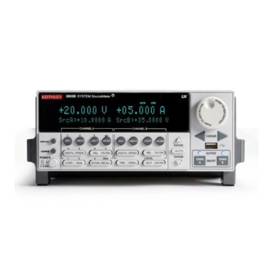
1-1. The descriptions of the front panel controls follow Figure 1-1. Figure 1-1 Front panel (see definitions below figure) Model 2601A and Model 2611A 2601A KEITHLEY SourceMeter POWER Model 2602A and Model 2612A 2602A KEITHLEY SourceMeter OUTPUT POWER ON/OFF Return to Section Topics 2600AS-901-01 Rev. - Page 33 Series 2600A System SourceMeter® Instruments Reference Manual Section 1: Getting Started NOTE The Models 2601A, 2611A, and 2635A have one source measure channel (Channel A), and the Models 2602A, 2612A, and 2636A have two source measure channels (Channel A and Channel B). 1.
- Page 34 Section 1: Getting Started Series 2600A System SourceMeter® Instruments Reference Manual Bottom row LOAD Loads factory or user-defined scripts for execution. Runs the last selected factory or user-defined scripts. STORE Stores readings, source values, and timestamp values in one of two internal buffers per channel for later recall.
-
Page 35: Rear Panel Summaries
Series 2600A System SourceMeter® Instruments Reference Manual Section 1: Getting Started Rear panel summaries The rear panels of Models 260A, 2611A and Models 2602A, 2612A are shown in Figure 1-2. The descriptions of the rear panel components follow Figure 1-2. The rear panels of Models 2625A and 2636A are shown in Figure 1-3. - Page 36 (Keithley Instruments Model 7009-5) for connection to the PC. 8 TSP-Link Expansion interface that allows a Series 2600A and other TSP-enabled instruments to trigger and communicate with each other. Use a category 5e or higher LAN crossover cable (Keithley Instruments part number CA-180-3A). 9 Power module Contains the AC line receptacle and power line fuse.
-
Page 37: Figure 1-3 Models 2635A/2636A Rear Panels
Series 2600A System SourceMeter® Instruments Reference Manual Section 1: Getting Started Figure 1-3 Models 2635A/2636A rear panels (see definitions below figure) 2600AS-901-01 Rev. B / September 2008 Return to Section Topics 1-11... - Page 38 PC (Keithley Instruments Model 7009-5). 7. TSP-Link Expansion interface that allows a Series 2600A and other TSP-enabled instruments to trigger and communicate with each other. Use a category 5e or higher LAN crossover cable (Keithley Instruments part number CA-180-3A). 8. Power module Contains the AC line receptacle and power line fuse.
-
Page 39: Cooling Vents
Ground Module 9. Triax connector Channel A and Channel B low noise chassis ground triax connectors. Use only low-noise triax cables such as the Keithley Model 7078-TRX. Connector terminals and associated triax cable connectors are as follows: Table 1-2... -
Page 40: Power-Up
Section 1: Getting Started Series 2600A System SourceMeter® Instruments Reference Manual Rack mounting high power dissipation equipment adjacent to the Series 2600A could cause excessive heating to occur. The specified ambient temperature must be maintained around the surfaces of the Series 2600A to specified accuracies. -
Page 41: Power-Up Sequence
(error messages are listed in Appendix NOTE If a problem develops while the instrument is under warranty, return it to Keithley Instruments, Inc., for repair. Assuming no errors occur, the Series 2600A will power-up as follows: The OUTPUT indicators and display pixels flash briefly. -
Page 42: Display Modes
Section 1: Getting Started Series 2600A System SourceMeter® Instruments Reference Manual select MENU > BEEPER. Choose one of the following: • ENABLE • DISABLE Via remote, use the beeper.enable command to control the beeper. For example, the following enables the beeper: beeper.enable = 1 Display modes Use the DISPLAY key to cycle through the various display modes shown in... -
Page 43: Editing Controls
Series 2600A System SourceMeter® Instruments Reference Manual Section 1: Getting Started Editing controls Source and compliance editing When the Series 2600A is in the edit mode (EDIT indicator on), the editing controls are used to set source and compliance values. Note that source auto ranging will turn off when editing the source value. -
Page 44: Menu Navigation
Section 1: Getting Started Series 2600A System SourceMeter® Instruments Reference Manual Menu navigation When the Series 2600A is not in the edit mode (the EDIT indicator is not illuminated), the editing controls are used to navigate the Main and Configuration menus to make selections and/or set values (see Menu navigation for more information). -
Page 45: Menu Types
Series 2600A System SourceMeter® Instruments Reference Manual Section 1: Getting Started Menu types Many aspects of operation are configured through menus. There are two types of menus. Refer to Menu navigation for more details on using menus. Main menu The main menu is summarized in Table 1-3, along with the reference for each main selection. -
Page 46: Table 1-4 Configuration Menus
Section 1: Getting Started Series 2600A System SourceMeter® Instruments Reference Manual Menu selection Description Reference BEEPER Controls the key beeps. Section 1 ENABLE Enables the key beeps. DISABLE Disables key beeps. LINE-FREQ Configure the line frequency. Section 1 AUTO Automatically selects the line frequency. 50Hz 60Hz SYSTEM-INFO... -
Page 47: Interface Configuration
USB storage overview The Keithley Instruments Series 2600A System SourceMeter® instrument includes a USB port on the front panel. To store scripts and to transfer files from the instrument to the host PC, insert a USB flash drive into the USB port. -
Page 48: Using The File System
Section 1: Getting Started Series 2600A System SourceMeter® Instruments Reference Manual Figure 1-5 USB port Using the file system File system navigation The Lua fs library provides the command set necessary to navigate the file system and list the available files on a flash drive. The instrument encapsulates this command set as an fs logical instrument, so that the file system of any given node is available to the entire TSP-Link system. -
Page 49: Dut Test Connections
Section 2 DUT Test Connections In this section: Topic Page Input/output connectors ..............Input/output LO and chassis ground..........Sensing methods................2-wire local sensing............... 4-wire remote sensing ..............Sense mode selection ..............Contact check connections .............. Multiple SMU connections ..............2-10 Guarding and shielding .............. -
Page 50: Input/Output Connectors
Series 2600A System SourceMeter® Instruments Reference Manual Input/output connectors ® The Keithley Instruments Series 2600A System SourceMeter Models 2601A, 2602A, 2611A, and 2612A use screw connectors for input and output connections to devices under test (DUTs). The Model 2602A/2612A uses two connectors as shown in... -
Page 51: Figure 2-1 2602A/2612A Input/Output Connectors
Series 2600A System SourceMeter® Instruments Reference Manual Section 2: DUT Test Connections Figure 2-1 2602A/2612A input/output connectors Channel B Channel A CHANNEL A CHANNEL B Captive screw (2 per terminal block) HI = Input/Output HI Each terminal block uses two captive S HI = Sense HI screws to secure it to the rear panel. -
Page 52: Input/Output Lo And Chassis Ground
Section 2: DUT Test Connections Series 2600A System SourceMeter® Instruments Reference Manual Input/output LO and chassis ground As shown in Figure 2-3, SMU input/output LOs are available at the rear panel terminal blocks. Input/output LOs are not connected between channels and are electrically isolated from chassis ground. -
Page 53: Figure 2-4 Model 2636A Input/Output And Chassis Ground
Series 2600A System SourceMeter® Instruments Reference Manual Section 2: DUT Test Connections Figure 2-4 Model 2636A input/output and chassis ground Figure 2-5 Model 2602A/2612A Low-Noise Chassis Ground Banana Jack and Chassis Screw DO NOT 2600AS-901-01 Rev. B / September 2008 Return to Section Topics... -
Page 54: Sensing Methods
Section 2: DUT Test Connections Series 2600A System SourceMeter® Instruments Reference Manual Figure 2-6 Model 2636A Channel B LO Channel A LO Floating Floating Channel A LO Channel B LO Chassis GND When connecting to the model 2611A, 2612A, 2635A, and 2636A WARNING SMU outputs, with cables not rated for voltages above 42V, such as the 2600A-ALG-2, you must disable the high voltage output by... -
Page 55: Figure 2-7 Model 2602A/2612A Two-Wire Connections (Local Sensing)
Series 2600A System SourceMeter® Instruments Reference Manual Section 2: DUT Test Connections Figure 2-7 Model 2602A/2612A two-wire connections (local sensing) Figure 2-8 Model 2636A two-wire connections (local sensing, non-floating) Figure 2-9 Model 2636A two-wire connections (local sensing, floating) 2600AS-901-01 Rev. B / September 2008 Return to Section Topics... -
Page 56: 4-Wire Remote Sensing
Section 2: DUT Test Connections Series 2600A System SourceMeter® Instruments Reference Manual 4-wire remote sensing When sourcing and/or measuring voltage in a low-impedance test circuit (see Figure 2-10), there can be errors associated with IR drops in the test leads. Voltage source and measure accuracy are optimized by using 4-wire remote sense connections. -
Page 57: Sense Mode Selection
Series 2600A System SourceMeter® Instruments Reference Manual Section 2: DUT Test Connections Sense mode selection The sense mode can be set for 2-wire local or 4-wire remote connections. Front panel sense selection Table 2-1 summarizes the steps to check and/or change the sense mode front panel. When in the menu structure, use the navigation wheel (or CURSOR keys) to position the blinking cursor on the desired menu item, and press ENTER to select it. -
Page 58: Multiple Smu Connections
A typical application is for SMU B to source a range of gate voltages, while SMU A sources voltage to power the device and measures current at each gate voltage. Figure 2-13 Model 2602A/2612A two SMUs connected to a 3-terminal device (local sensing) Keithley Model 2602A/2612A 2-10 Return to Section Topics 2600AS-901-01 Rev. -
Page 59: Figure 2-14 Model 2636A, Two Smus Connected To A 3-Terminal Device (Local Sensing, Floating)
Setting this SMU to output 0V effectively connects the source terminal of the JFET to signal low. Figure 2-15 Three SMUs connected to a 3-terminal device Keithley Model 2602A/2612A-1 Keithley Model 2602A/2612A-2 2600AS-901-01 Rev. B / September 2008 Return to... -
Page 60: Guarding And Shielding
Section 2: DUT Test Connections Series 2600A System SourceMeter® Instruments Reference Manual Figure 2-16 Model 2636A, three SMUs connected to a 3-terminal device (local sensing, non-floating) Guarding and shielding Source-measure performance and safety are optimized with the effective use of guarding and shielding (noise and safety shields). -
Page 61: Guarding
Series 2600A System SourceMeter® Instruments Reference Manual Section 2: DUT Test Connections Guarding A driven guard is always enabled and provides a buffered voltage that is at the same level as the input/output HI voltage. The purpose of guarding is to eliminate the effects of leakage current (and capacitance) that can exist between input/output high and low. -
Page 62: Noise Shield
Section 2: DUT Test Connections Series 2600A System SourceMeter® Instruments Reference Manual Figure 2-19 Model 2636A High-impedance guarding (non-floating) Noise shield A noise shield (see Figure 2-20) is used to prevent unwanted signals from being induced into the test circuit. Low-level signals may benefit from effective shielding. The metal noise shield surrounds the test circuit and should be connected to SMU LO as shown in Figure 2-20. -
Page 63: Figure 2-21 Model 2636A Noise Shield (Non-Floating)
Series 2600A System SourceMeter® Instruments Reference Manual Section 2: DUT Test Connections Figure 2-21 Model 2636A noise shield (non-floating) Figure 2-22 Model 2636A noise shield (non-floating) 2600AS-901-01 Rev. B / September 2008 Return to Section Topics 2-15... -
Page 64: Safety Shield
Section 2: DUT Test Connections Series 2600A System SourceMeter® Instruments Reference Manual Figure 2-23 Model 2636A noise shield (floating) Safety shield A safety shield must be used whenever hazardous voltages (>30 V , 42 V ) will be present in peak the test circuit. -
Page 65: Figure 2-24 Safety Shield For Hazardous Voltage Using Two 2601A/2602A Channels (>42V)
Series 2600A System SourceMeter® Instruments Reference Manual Section 2: DUT Test Connections NOTE Floating an SMU may also cause test circuit voltage to exceed 42V (see Floating an SMU for more information). Figure 2-24 Safety shield for hazardous voltage using two 2601A/2602A channels (>42V) Figure 2-25 Model 2601A/2602A-1 connections for test circuit shown in Figure 2-24... -
Page 66: Using Shielding And Guarding Together
Section 2: DUT Test Connections Series 2600A System SourceMeter® Instruments Reference Manual Figure 2-27 Model 2601A/2602A-1 connections for test circuit shown in Figure 2-26 Figure 2-28 Model 2636A connections for test circuit shown in Figure 2-26 Using shielding and guarding together Figure 2-29 shows connections for a test system that uses a noise shield, a safety shield, and guarding. -
Page 67: Model 2601A/2602A-1 Connections For Noise Shield Safety Shield, And Guarding
Series 2600A System SourceMeter® Instruments Reference Manual Section 2: DUT Test Connections Figure 2-29 Model 2601A/2602A-1 connections for noise shield, safety shield, and guarding Figure 2-30 Model 2636A connections for noise shield, safety shield, and guarding 2600AS-901-01 Rev. B / September 2008 Return to Section Topics 2-19... -
Page 68: Test Fixture
Section 2: DUT Test Connections Series 2600A System SourceMeter® Instruments Reference Manual Test fixture A test fixture can be used for an external test circuit. The test fixture can be a metal or nonmetallic enclosure, and is typically equipped with a lid. The test circuit is mounted inside the test fixture. When hazardous voltages (>30 Vrms, 42 Vpeak) will be present, the test fixture must have the following safety requirements: WARNING... -
Page 69: Floating The Series 2600A
Series 2600A System SourceMeter® Instruments Reference Manual Section 2: DUT Test Connections external voltage source. Notice that output low of the voltage source is connected to chassis earth ground. For the test circuit shown in Figure 2-31, the Series 2600A must float off chassis earth ground. As shown, SMU LO of the Series 2600A is floating +10V above chassis earth ground. -
Page 70: Model 2601A/2602A-1 Smu Connections
Section 2: DUT Test Connections Series 2600A System SourceMeter® Instruments Reference Manual Figure 2-32 Model 2601A/2602A-1 SMU connections + – Figure 2-33 Model 2636A SMU connections for the floating configuration shown in Figure 2-31 2-22 Return to Section Topics 2600AS-901-01 Rev. B / September 2008... -
Page 71: Output-Off States
Series 2600A System SourceMeter® Instruments Reference Manual Section 2: DUT Test Connections Output-off states When a SMU is turned off, it may not be completely isolated from the external circuit that it is connected to. There are three output-off states for a Series 2600A SMU: Normal, High Impedance or zero. - Page 72 Section 2: DUT Test Connections Series 2600A System SourceMeter® Instruments Reference Manual NOTE The OUTPUT OFF STATE menu can also be accessed by navigating the configuration menu that is displayed by pressing the CONFIG key. With the OUTPUT OFF STATE menu displayed, select the desired output-off state: HI-Z (high-impedance), NORMAL, or ZERO.
-
Page 73: Table 3-1 Source-Measure Capabilities
Section 3 Basic Operation In this section: Topic Page Overview..................... Operation overview ................Source-measure capabilities............Compliance limit................Setting the compliance limit ............Basic circuit configurations............Operation considerations ..............Warm-up ..................Auto zero..................NPLC caching ................Basic source-measure procedure............ Front panel source-measure procedure........ -
Page 74: Basic Operation
Section 3: Basic Operation Series 2600A System SourceMeter® Instruments Reference Manual Overview The documentation in this section provides basic operating instructions for the Keithley ® Instruments Series 2600A System SourceMeter instrument and includes the following: • Operation overview • Operation considerations •... -
Page 75: Compliance Limit
Series 2600A System SourceMeter® Instruments Reference Manual Section 3: Basic Operation Table 3-1 Source-measure capabilities Model 2601A/2602A Model 2611A/2612A Model 2635A/2636A Range Source Measure Range Source Measure Range Source Measure 100mV ±101mV ±102mV 200mV ±202mV ±204mV 200mV +/-202mV +/-204mV ±1.01V ±1.02V ±2.02V ±2.04V... -
Page 76: Setting The Compliance Limit
Section 3: Basic Operation Series 2600A System SourceMeter® Instruments Reference Manual Table 3-2 Maximum compliance values Model 2601A/2602A Model 2611A/2612A Model 2635A/2636A Maximum Maximum Maximum Source Source Source compliance compliance compliance range range range value value value 100mV 200mV 1.5A 200mV 1.5A 1.5A... -
Page 77: Basic Circuit Configurations
Series 2600A System SourceMeter® Instruments Reference Manual Section 3: Basic Operation A returned value of 1 indicates that the voltage limit has been reached if the unit is configured as a current source, or that the current limit has been reached if the unit is configured as a voltage source. -
Page 78: Auto Zero
Section 3: Basic Operation Series 2600A System SourceMeter® Instruments Reference Manual Auto zero The Series 2600A uses a ratiometric A/D conversion technique. To ensure accuracy of readings, the instrument must periodically obtain fresh measurements of its internal ground and voltage reference. -
Page 79: Nplc Caching
Series 2600A System SourceMeter® Instruments Reference Manual Section 3: Basic Operation smua.measure.autozero = smua.AUTOZERO_AUTO Table 3-5 Auto zero command and options Command Description Disable auto zero** smuX.measure.autozero = smuX.AUTOZERO_OFF Force one ref and zero smuX.measure.autozero = smuX.AUTOZERO_ONCE Force ref and zero with each smuX.measure.autozero = smuX.AUTOZERO_AUTO measurement *smuX = smua for the Model 2601A/2611A/2635A;... - Page 80 Section 3: Basic Operation Series 2600A System SourceMeter® Instruments Reference Manual Move the cursor to the digit to change, then press the navigation wheel to enter the EDIT mode, as indicated by the EDIT indicator. Use the RANGE keys to select a range that will accommodate the value you want to set. (See Section 6 for range information.) For best accuracy, use the lowest possible source...
-
Page 81: Remote Source-Measure Procedure
Series 2600A System SourceMeter® Instruments Reference Manual Section 3: Basic Operation Remote source-measure procedure Basic source-measurement procedures can also be performed via remote by sending appropriate commands in the right sequence. Table 3-6 summarizes basic source-measure commands. See Section 19 for more information on using these commands. -
Page 82: Triggering In Local Mode
Section 3: Basic Operation Series 2600A System SourceMeter® Instruments Reference Manual Source-measure programming example The set-up and command sequence for a basic source-measure procedure is shown below: • Source function and range: volts, auto range • Source output level: 5V •... -
Page 83: Configuring Trigger Attributes In Local Mode
Series 2600A System SourceMeter® Instruments Reference Manual Section 3: Basic Operation Figure 3-2 Local triggering Configuring trigger attributes in local mode • From the front panel, press CONFIG > TRIG. The following menu items are shown: TRIGGER-IN: Use these options to select the trigger-in source: •... -
Page 84: Measure Only
Section 3: Basic Operation Series 2600A System SourceMeter® Instruments Reference Manual Press EXIT to return to normal display. Push OUTPUT to turn the output on and then press TRIG. A 2-second delay occurs before the first measurement. The unit cycles through measurements indefinitely with a 1s interval between measurements. -
Page 85: Sink Operation And Interface
Series 2600A System SourceMeter® Instruments Reference Manual Section 3: Basic Operation Sink operation and interface When operating as a sink (V and I have opposite polarity), the SourceMeter instrument is dissipating power rather than sourcing it. An external source (for example, a battery) or an energy storage device (i.e., capacitor) can force operation into the sink region. -
Page 86: Ohms Sensing
Section 3: Basic Operation Series 2600A System SourceMeter® Instruments Reference Manual WARNING Hazardous voltages may be present on the output and guard terminals. To prevent electrical shock that could cause injury or death, NEVER make or break connections to the Series 2600A while the output is on. -
Page 87: Sense Selection
Series 2600A System SourceMeter® Instruments Reference Manual Section 3: Basic Operation Figure 3-3 2-wire resistance sensing Figure 3-4 4-wire resistance sensing Sense selection Front panel sense selection To select sensing mode: 2600AS-901-01 Rev. B / September 2008 Return to Section Topics 3-15... -
Page 88: Remote Ohms Programming
Section 3: Basic Operation Series 2600A System SourceMeter® Instruments Reference Manual Press the CONFIG key then press MEAS. Choose V-MEAS, and then press ENTER or the navigation wheel. Select SENSE-MODE, then press ENTER. Choose 2-WIRE or 4-WIRE, as desired, and then press ENTER or the navigation wheel. Remote sense selection Use the smuX.sense command to control sense selection by remote. -
Page 89: Power Measurements
Series 2600A System SourceMeter® Instruments Reference Manual Section 3: Basic Operation Power measurements Power calculations Power readings are calculated from the sourced and measured current or voltage as follows: × P = V Where: P is the calculated power V is the sourced or measured voltage I is the measured or sourced current Basic power measurement procedure Perform the following steps to perform power measurements. -
Page 90: Contact Check Measurements
Section 3: Basic Operation Series 2600A System SourceMeter® Instruments Reference Manual Power programming example The set-up and command sequence for a typical power measurement is shown below: • Source function: voltage, auto source range, 5V output • Current measure function and range: current, auto •... -
Page 91: Contact Check Commands
Series 2600A System SourceMeter® Instruments Reference Manual Section 3: Basic Operation Contact check commands Table 3-7 summarizes basic contact check commands. See Section 19 for more information on using these commands. Table 3-7 Basic contact check commands Command Description Determine if contact resistance is lower than threshold. flag = smuX.contact.check() Return the contact resistance. -
Page 92: Contact Check Programming Example
Section 3: Basic Operation Series 2600A System SourceMeter® Instruments Reference Manual Contact check programming example The command sequence for a typical contact measurement is shown below. These commands set the contact check speed to fast and the threshold to 10Ω. A contact check measurement against the threshold is then made. -
Page 93: Recalling A Saved Setup
Series 2600A System SourceMeter® Instruments Reference Manual Section 3: Basic Operation Recalling a saved setup Setups can be recalled from internal nonvolatile memory or a USB flash drive at any time. To recall a saved setup: Press the MENU key to access the main menu. Select SETUP, then press ENTER. - Page 94 Section 3: Basic Operation Series 2600A System SourceMeter® Instruments Reference Manual Selecting the power-on setup The setup.poweron attribute is used to select which setup to return to upon power-up. To select the power-on setup: setup.poweron = n -- Select power-on setup. Where: n = 0 (*RST defaults) n = 1 to 5 (user setups 1-5)
- Page 95 Section 4 Source-Measure Concepts In this section: Topic Page Overview ..................... Compliance limit ................Maximum compliance..............Compliance principles ..............Overheating protection ..............Power equations to avoid overheating .......... Operating boundaries ............... Source or sink ................Continuous power operating boundaries........I-Source operating boundaries ............
-
Page 96: Source-Measure Concepts
Guard Compliance limit ® When sourcing voltage, the Keithley Instruments Series 2600A System SourceMeter instrument can be set to limit current. Conversely, when sourcing current, the SourceMeter instrument can be set to limit voltage. The Series 2600A output does not exceed the compliance limit, except for the... -
Page 97: Overheating Protection
Series 2600A System SourceMeter® Instruments Reference Manual Section 4: Source-Measure Concepts source will switch from a V-source to an I-source (or from an I-source to a V-source) when in compliance. As an example, assume the following: SourceMeter instrument: V = 10V; I = 10mA CMPL Device under test (DUT) resistance: 10Ω... - Page 98 Section 4: Source-Measure Concepts Series 2600A System SourceMeter® Instruments Reference Manual General SourceMeter instrument power equation ( ) DC ≤ – – – = The maximum power generated in a SourceMeter instrument channel that can be properly dissipated by the SourceMeter instrument cooling system. = The ambient temperature of the SourceMeter instrument operating environment.
-
Page 99: Table 4-2 Model 2601A/2602A Maximum Duty Cycle Equation Constants
Series 2600A System SourceMeter® Instruments Reference Manual Section 4: Source-Measure Concepts This maximum duty cycle equation is an approximation. In general, if the CAUTION duty cycle calculation yields a number > 90%, then DC under those conditions should not cause the SourceMeter instrument to overheat. However, if the calculation yields a number <... -
Page 100: Operating Boundaries
Section 4: Source-Measure Concepts Series 2600A System SourceMeter® Instruments Reference Manual Example 3: Using a Model 2612A to charge a 12V battery by sourcing 100mA and then discharging the battery by sinking 5A, while operating at 35°C ambient temperature; what is the maximum duty cycle? Assuming the 20V range will be used to measure the voltage: ) 0.1 –... -
Page 101: I-Source Operating Boundaries
Series 2600A System SourceMeter® Instruments Reference Manual Section 4: Source-Measure Concepts Figure 4-1 Model 2601A/2602A continuous power operating boundaries £ Model 2611A/2635A/2612A/2636A continuous power operating boundaries The general operating boundaries for Model 2611A/2612A continuous power output are shown in Figure 4-2 (see General SourceMeter instrument power equation in this section for derating... -
Page 102: Figure
Section 4: Source-Measure Concepts Series 2600A System SourceMeter® Instruments Reference Manual Figure 4-3A shows the output characteristics for the I-Source. As shown, the Series 2601A and 2602A can output up to 1.01A at 40V, or 3.03A at 6V. Note that when sourcing more than 1.01A, voltage is limited to 6V. -
Page 103: Figure
Series 2600A System SourceMeter® Instruments Reference Manual Section 4: Source-Measure Concepts Model 2611A/2612A/2635A/2636A I-Source operating boundaries Figure 4-4 shows the operating boundaries for the I-Source. Only the first quadrant of operation is covered. Operation in the other three quadrants is similar. Figure 4-4A shows the output characteristics for the I-Source. -
Page 104: Figure
Section 4: Source-Measure Concepts Series 2600A System SourceMeter® Instruments Reference Manual Load considerations The boundaries the SourceMeter instrument operates in depends on the load (DUT) that is connected to its output. Figure 4-5 shows operation examples for resistive loads that are 50Ω and 200Ω, respectively. -
Page 105: V-Source Operating Boundaries
Series 2600A System SourceMeter® Instruments Reference Manual Section 4: Source-Measure Concepts V-Source operating boundaries Model 2601A/2602A V-Source operating boundaries Figure 4-6 shows the operating boundaries for the V-Source. Only the first quadrant of operation is covered. Operation in the other three quadrants is similar. Figure 4-6A shows the output characteristics for the V-Source. -
Page 106: Figure
Section 4: Source-Measure Concepts Series 2600A System SourceMeter® Instruments Reference Manual Model 2611A/2612A/2635A/2636A V-Source operating boundaries Figure 4-7 shows the operating boundaries for the V-Source. Only the first quadrant of operation is covered. Operation in the other three quadrants is similar. Figure 4-7A shows the output characteristics for the V-Source. -
Page 107: Figure
Series 2600A System SourceMeter® Instruments Reference Manual Section 4: Source-Measure Concepts Load considerations The boundaries the SourceMeter instrument operates in depends on the load (DUT) that is connected to the output. Figure 4-8 shows operation examples for resistive loads that are 2kΩ and 800Ω, respectively. -
Page 108: V-Source Operating Examples
Section 4: Source-Measure Concepts Series 2600A System SourceMeter® Instruments Reference Manual Figure 4-8 V-Source operating examples 4-14 Return to Section Topics 2600AS-901-01 Rev. B / September 2008... -
Page 109: Source I Measure I, Source V Measure V
Series 2600A System SourceMeter® Instruments Reference Manual Section 4: Source-Measure Concepts Source I measure I, source V measure V The SourceMeter instrument can measure the function it is sourcing. When sourcing a voltage, you can measure voltage. Conversely, if you are sourcing current, you can measure the output current. -
Page 110: Source V
Section 4: Source-Measure Concepts Series 2600A System SourceMeter® Instruments Reference Manual Source V When configured to source voltage (V-Source) as shown in Figure 4-10, the SourceMeter instrument functions as a low-impedance voltage source with current limit capability and can measure current (I-Meter) or voltage (V-Meter). Sense circuitry is used to continuously monitor the output voltage and make adjustments to the V-Source as needed. -
Page 111: Contact Check
Series 2600A System SourceMeter® Instruments Reference Manual Section 4: Source-Measure Concepts V-Compliance must be set to a level that is higher than the measured CAUTION voltage. Otherwise, excessive current will flow into the SourceMeter instrument. This current could damage the SourceMeter instrument. Also, when connecting an external voltage to the I-Source, set the output off state to the high-impedance mode. -
Page 112: Guard
Section 4: Source-Measure Concepts Series 2600A System SourceMeter® Instruments Reference Manual Figure 4-12 Contact check circuit configuration Guard WARNING GUARD is at the same potential as output HI. Thus, if hazardous voltages are present at output HI, they are also present at the GUARD terminal. -
Page 113: Guard Connections
Series 2600A System SourceMeter® Instruments Reference Manual Section 4: Source-Measure Concepts Guard connections Guard is typically used to drive the guard shields of cables and test fixtures. Guard is extended to a test fixture from the cable guard shield. Inside the test fixture, the guard can be connected to a guard plate or shield that surrounds the DUT. -
Page 114: Settling Time Considerations
Section 4: Source-Measure Concepts Series 2600A System SourceMeter® Instruments Reference Manual Figure 4-13 Comparison of unguarded and guarded measurements SourceMeter A. Unguarded SourceMeter B. Guarded Settling time considerations Measurement settling time considerations Several outside factors can influence measurement settling times. Effects such as dielectric absorption, cable leakages, and noise can all extend the times required to make stable measurements. - Page 115 Series 2600A System SourceMeter® Instruments Reference Manual Section 4: Source-Measure Concepts current ranges and associated default delays. In addition, a 1Hz analog filter is used by default on the 1nA and 100pA ranges. Table 4-4 1, 2 Current Measure Settling Time Time required to reach 0.1% of final value after source level command is processed on a fixed range.
-
Page 116: Reduction In Gain-Bandwidth
Section 4: Source-Measure Concepts Series 2600A System SourceMeter® Instruments Reference Manual This filter is only active when the amps measure range is 1nA/100pA. Setting the attribute to zero disables the filter. Reduction in gain-bandwidth The settling time of the SMU can be influenced by the impedance of the DUT in several ways. One influence is caused by an interaction between the impedances of the SMU current source feedback element and the DUT. -
Page 117: High-Capacitance Mode
Section 5 High-Capacitance Mode In this section: Topic Page Overview..................... Understanding high-capacitance mode........... Understanding source settling times ..........Adjusting the voltage source ............Enabling high-capacitance mode............. Front panel ..................Command interface ............... -
Page 118: Overview
Section 5: High-Capacitance Mode Series 2600A System SourceMeter® Instruments Reference Manual Overview ® The Keithley Instruments Series 2600A System SourceMeter instrument features a high- capacitance mode. Because the source measure unit (SMU) has the ability to measure low current, issues can arise when driving a capacitive load. -
Page 119: Adjusting The Voltage Source
Series 2600A System SourceMeter® Instruments Reference Manual Section 5: High-Capacitance Mode Table 5-1 Models 2601A and 2602A source settling times High Range Normal mode capacitance mode 100 mV 50 µs 200 µs 50 µs 200 µs 100 µs 200 µs 40 V 150 µs 7 ms... -
Page 120: Enabling High-Capacitance Mode
Section 5: High-Capacitance Mode Series 2600A System SourceMeter® Instruments Reference Manual The total response times while in high-capacitance mode are a combination of the time spent charging the capacitor (current limit) or the response time, whichever is greater. There is a direct relationship between the current limit and the charging time. -
Page 121: Command Interface
Series 2600A System SourceMeter® Instruments Reference Manual Section 5: High-Capacitance Mode Command interface Turning on High-C mode has the following effects on the SMU settings: • smuX.measure.autorangei is set to smuX.AUTORANGE_FOLLOW_LIMIT and cannot be changed. • Current ranges below 1uA are not accessible. •... -
Page 122: Figure
Section 5: High-Capacitance Mode Series 2600A System SourceMeter® Instruments Reference Manual -- limiti = 1A -- sourcedelay = 300ms -- measurei = 10uA range -- measuredelay = 100ms NOTE Adjust the voltage level and source delays based on the value and type of capacitor along with the magnitude of the voltage step and the current measure range. -
Page 123: Range, Digits, Speed, Rel, And Filters
Section 6 Range, Digits, Speed, Rel, and Filters In this section: Topic Page Overview..................... Range....................Available ranges................Maximum source values and readings.......... Ranging limitations ................ Manual ranging ................Auto ranging .................. Low range limits ................Range considerations ..............Range programming .............. -
Page 124: Overview
µA), to indicate that the previous measurement is not recent. This usually happens when a change occurs such as selecting a different range. Available ranges Table 6-1 lists the available source and measurement ranges for the Keithley Instruments Series ® 2600A System SourceMeter instruments. -
Page 125: Maximum Source Values And Readings
Series 2600A System SourceMeter® Instruments Reference Manual Section 6: Range, Digits, Speed, Rel, and Filters Maximum source values and readings The full-scale output for each voltage and current source range is 101% of the selected range, while the full-scale measurement is 102% of the range. For example, ±1.01A is the full-scale source value for the 1A range, and ±102mA is the full-scale reading for the 100mA measurement range. -
Page 126: Range Considerations
Section 6: Range, Digits, Speed, Rel, and Filters Series 2600A System SourceMeter® Instruments Reference Manual Use EXIT to back out of the menu structure. Range considerations The source range and measure range settings can interact depending on the source function. Additionally, the output state (on/off) can affect how the range is set. -
Page 127: Table 6-2 Range Commands
Series 2600A System SourceMeter® Instruments Reference Manual Section 6: Range, Digits, Speed, Rel, and Filters Table 6-2 Range commands Commands Description Measure range commands: Enable current measure auto range. smuX.measure.autorangei = smuX.AUTORANGE_ON Disable current measure auto range. smuX.measure.autorangei = smuX.AUTORANGE_OFF Enable voltage measure auto range. -
Page 128: Digits
Section 6: Range, Digits, Speed, Rel, and Filters Series 2600A System SourceMeter® Instruments Reference Manual Digits The display resolution of the measured reading depends on the DIGITS setting. This setting is global, which means the digits setting selects display resolution for all measurement functions. The DIGITS setting has no effect on the remote reading format. -
Page 129: Setting Speed
Series 2600A System SourceMeter® Instruments Reference Manual Section 6: Range, Digits, Speed, Rel, and Filters provides the best common-mode and normal-mode noise rejection, but has the slowest reading rate. In-between settings are a compromise between speed and noise. The default power-on speed setting is NORMAL (1 PLC). -
Page 130: Rel
Section 6: Range, Digits, Speed, Rel, and Filters Series 2600A System SourceMeter® Instruments Reference Manual The rel (relative) feature can be used to null offsets or subtract a baseline reading from present and future readings. With rel enabled, subsequent readings will be the difference between the actual input value and the rel value as follows: Displayed Reading = Actual Input - Rel Value Once a rel value is established for a measurement function, the value is the same for all ranges. -
Page 131: Remote Rel Programming
Series 2600A System SourceMeter® Instruments Reference Manual Section 6: Range, Digits, Speed, Rel, and Filters Remote rel programming Rel commands Rel commands are summarized in Table 6-5. Table 6-5 Rel commands Command Description To set rel values: Set current rel value. smuX.measure.rel.leveli = relval Set power rel value. -
Page 132: Front Panel Filter Control
Section 6: Range, Digits, Speed, Rel, and Filters Series 2600A System SourceMeter® Instruments Reference Manual The median filter is used to pass the “middle-most” reading from a group of readings that are arranged according to size. The median filter uses a first-in, first-out stack similar to the moving average filter. -
Page 133: Figure
Series 2600A System SourceMeter® Instruments Reference Manual Section 6: Range, Digits, Speed, Rel, and Filters Figure 6-1 Moving average and repeating filters A. Type - Moving Average, Readings = 10 B. Type - Repeating, Readings = 10 2600AS-901-01 Rev. B / September 2008 Return to Section Topics 6-11... -
Page 134: Remote Filter Programming
Section 6: Range, Digits, Speed, Rel, and Filters Series 2600A System SourceMeter® Instruments Reference Manual Figure 6-2 Median Filter Conversion Conversion Conversion Middle Middle Middle value value value reading reading reading A. Type - Median, Readings = 3 Remote filter programming Filter commands Table 6-6 summarizes filter commands. -
Page 135: Reading Buffers
Section 7 Reading Buffers In this section: Topic Page Reading buffer overview ..............Working with reading buffers in the local state......Reading buffer options ..............Configuring reading buffers ............Appending or overwriting existing reading buffers ......Storage operation ................Saving reading buffers .............. -
Page 136: Reading Buffer Overview
Reading buffers capture measurements, ranges, the instrument status, and the output state of the ® Keithley Instruments Series 2600A SourceMeter instrument. The Series 2600A has two dedicated reading buffers per channel. You can use the dedicated reading buffers to acquire readings or you can use the ICL command to create dynamic reading buffers. -
Page 137: Configuring Reading Buffers
Series 2600A System SourceMeter® Instruments Reference Manual Section 7: Reading Buffers • BUFFER2: Configure Buffer 2. – CLEAR: Clear buffer (YES or NO). – ELEMENTS: Enable (ON) or disable (OFF) data storage elements; SRC-VAL (source value) or TSTAMP (time stamp). •... -
Page 138: Storage Operation
Section 7: Reading Buffers Series 2600A System SourceMeter® Instruments Reference Manual Storage operation Use this option to initiate a storage operation and to configure the number of readings acquired during a store operation. The count can range from 1 to 60,000 with time stamps and source values enabled, to over 140,000 with time stamps and source values disabled. -
Page 139: Recalling Readings
Series 2600A System SourceMeter® Instruments Reference Manual Section 7: Reading Buffers Use the navigation wheel to select the desired reading buffer. Use the navigation wheel to change the file name. Push the navigation wheel or the ENTER key to save the file. Push EXIT to return to the main menu. -
Page 140: Table 7-1 Smu Buffer Example
Section 7: Reading Buffers Series 2600A System SourceMeter® Instruments Reference Manual A reading buffer is based on a Lua table. The measurements are accessed by ordinary array accesses. If rb is a reading buffer, the first measurement is accessed as rb[1] and the 9th measurement as rb[9], and so on. -
Page 141: Reading Buffer Commands
Series 2600A System SourceMeter® Instruments Reference Manual Section 7: Reading Buffers Reading buffer commands Table 7-2 summarizes commands associated with the reading buffers. See Section 19 for more detailed information on the commands for the reading buffers. Table 7-2 Reading buffer commands Command Description Saves the reading buffer to the Series 2600A. -
Page 142: Table 7-3 Buffer Storage Control Attributes
Section 7: Reading Buffers Series 2600A System SourceMeter® Instruments Reference Manual Table 7-3 Buffer storage control attributes Storage attribute Description The append modes are either off or on. When the append mode is off, a new appendmode measurement to this buffer will overwrite the previous contents. When the append mode is on, the first new measurement will be stored at what was formerly rb[n+1]. -
Page 143: Buffer Status
Series 2600A System SourceMeter® Instruments Reference Manual Section 7: Reading Buffers Note that readings is the default reading attribute and can be omitted. Thus, the following would also return 100 Channel A readings from Buffer 1: printbuffer(1, 100, smua.nvbuffer1) Table 7-7 Recall attributes Recall attribute Description... -
Page 144: Dynamic Reading Buffers
Section 7: Reading Buffers Series 2600A System SourceMeter® Instruments Reference Manual Dynamic reading buffers Reading buffers can also be allocated dynamically. Dynamic reading buffers are created and allocated with the smuX.makebuffer(n) command, where n is the number of readings the buffer can store. - Page 145 Series 2600A System SourceMeter® Instruments Reference Manual Section 7: Reading Buffers -- Return source values 1-100. printbuffer(1, 100, smua.nvbuffer1.sourcevalues) Dual buffer example The listing below shows a programming example for storing both current and voltage readings using Buffer 1 for current and Buffer 2 to store voltage readings. The Series 2600A stores 100 current and voltage readings and then recalls all 100 sets of readings.
- Page 146 Section 7: Reading Buffers Series 2600A System SourceMeter® Instruments Reference Manual Dynamically allocated buffer example The listing below shows a programming example for storing data using an allocated buffer called mybuffer for Channel A. The Series 2600A stores 100 current readings in mybuffer and then recalls all the readings.
-
Page 147: Digital I/O
Section 8 Digital I/O In this section: Topic Page Digital I/O port ..................Port configuration ................Digital I/O configuration ..............Controlling digital I/O lines............. Output enable (Models 2601A/2602A)..........Overview ..................Operation..................Front panel control of output enable..........Remote control of output enable ........... -
Page 148: Digital I/O Port
Connecting cables Use a cable equipped with a male DB-25 connector (Keithley Instruments part number CA-126-1), or a Model 2600-TLINK cable to connect the digital I/O port to other Keithley Instruments models equipped with a Trigger Link (TLINK). Digital I/O lines The port provides 14 digital I/O lines. -
Page 149: Digital I/O Configuration
Series 2600A System SourceMeter® Instruments Reference Manual Section 8: Digital I/O Output enable and interlock line The Model 2601A/2602A output enable (OE) line and the Model 2611A/2612A/2635A/2636A interlock (INT) line of the digital I/O can be used with a switch in the test fixture or component handler. -
Page 150: Controlling Digital I/O Lines
Section 8: Digital I/O Series 2600A System SourceMeter® Instruments Reference Manual Controlling digital I/O lines Although the digital I/O lines are primarily intended for use with a device handler for limit testing, they can also be used for other purposes such as controlling external logic circuits. You can control lines either from the front panel or via remote interface. -
Page 151: Output Enable (Models 2601A/2602A)
Series 2600A System SourceMeter® Instruments Reference Manual Section 8: Digital I/O To remove write protection, repeat Step 1 thorough Step 4 and then enter the original value. Remote digital I/O commands Commands that control and access the digital I/O port are summarized in Table 8-2. -
Page 152: Operation
Section 8: Digital I/O Series 2600A System SourceMeter® Instruments Reference Manual WARNING When an interlock is required for safety, a separate circuit should be provided that meets the requirements of the application to reliably protect the operator from exposed voltages. The digital I/O port of the Model 2601A or 2602A is not suitable for control of safety circuits and should not be used to control a safety interlock. -
Page 153: Remote Control Of Output Enable
Series 2600A System SourceMeter® Instruments Reference Manual Section 8: Digital I/O Remote control of output enable Use one of these commands to control output enable action: smuX.source.outputenableaction = smuX.OE_NONE smuX.source.outputenableaction = smuX.OE_OUTPUT_OFF When set to smuX.OE_NONE, the Model 2601A/2602A does not take action when the output enable line is low. -
Page 154: Tsp-Link Synchronization Lines
Section 8: Digital I/O Series 2600A System SourceMeter® Instruments Reference Manual Figure 8-4 Using Model 2611A/2612A/2635A/2636A interlock TSP-Link synchronization lines The Series 2600A has three synchronization lines that you can use for triggering, digital I/O, and to synchronize multiple instruments on a TSP-Link network. Connecting to TSP-Link The TSP-Link synchronization lines are built into TSP-Link. -
Page 155: Remote Tsp-Link Synchronization Line Commands
Series 2600A System SourceMeter® Instruments Reference Manual Section 8: Digital I/O Table 8-3 Digital I/O bit weight. Decimal Hexadecimal Line # weighting weighting 0x0001 0x0002 0x0004 Remote TSP-Link synchronization line commands Commands that control and access the TSP-Link synchronization port are summarized in Table 8- 4. - Page 156 Section 8: Digital I/O Series 2600A System SourceMeter® Instruments Reference Manual This page left blank intentionally. 8-10 Return to Section Topics 2600AS-901-01 Rev. B / September 2008...
-
Page 157: Sweep Operation
Section 9 Sweep Operation In this section: Topic Page Overview..................... Section overview ................Sweep overview ................Sweep characteristics ............... Linear staircase sweeps..............Logarithmic staircase sweeps ............List sweeps..................Pulse mode sweeps ..............Configuring and running sweeps............. 9-10 Configuring other sweep attributes .......... -
Page 158: Overview
Sweep overview ® As shown in Figure 9-1, the Keithley Instruments Series 2600A System SourceMeter instrument can generate DC and pulsed sweeps to perform source-only sweeps, source-and-measure sweeps, or measure-only sweeps. The following sweeps can be programmed: DC and pulsed linear staircase sweeps: With these sweeps, the voltage or current increases or decreases in specific steps, beginning with a start voltage or current and ending with a stop voltage or current. -
Page 159: Sweep Characteristics
Series 2600A System SourceMeter® Instruments Reference Manual Section 9: Sweep Operation Figure 9-1 Sweep types Sweep characteristics NOTE For any of the sweep types, program a pulse mode sweep by configuring the end pulse action. Refer to Pulse mode sweeps more information. -
Page 160: Figure
Section 9: Sweep Operation Series 2600A System SourceMeter® Instruments Reference Manual Figure 9-2 Linear staircase sweep A linear staircase sweep is configured using a start level, a stop level, and the total number of points, including the start and stop points. The step size is determined by the start and stop levels, and the number of sweep points: step = (stop - start) / (points - 1) NOTE The number of sweep steps actually performed is determined by the... -
Page 161: Logarithmic Staircase Sweeps
Series 2600A System SourceMeter® Instruments Reference Manual Section 9: Sweep Operation Logarithmic staircase sweeps This sweep is similar to the linear staircase sweep. The steps, however, are done on a logarithmic scale. Figure 9-3 Figure 9-4 show sample sweeps. Like a linear staircase sweep, logarithmic sweeps are configured using a start level, a stop level and the number of points in between. -
Page 162: Figure
Section 9: Sweep Operation Series 2600A System SourceMeter® Instruments Reference Manual Figure 9-4 Decreasing logarithmic sweep Point Solving for k and b provides the following formulas: k = V start – – – log10(V log10(V ⎛ ⎞ start ------------------------------------------------------------------------------------------- - ⎝... -
Page 163: Figure
Series 2600A System SourceMeter® Instruments Reference Manual Section 9: Sweep Operation Figure 9-5 Logarithmic staircase sweep (1V to 10V, five steps) In this example: A = 0, V = 1, V = 10, N = 5 start Using the formula above k = 1 Step size (b) for the sweep in Figure 9-5 is calculated as follows:... -
Page 164: List Sweeps
Section 9: Sweep Operation Series 2600A System SourceMeter® Instruments Reference Manual Table 9-1 Logarithmic sweep points Measure Step Source level (V) point (N) number (i) Point 1 Point 2 1.7783 Point 3 3.1623 Point 4 5.6234 Point 5 When this sweep starts, the output will go to the start level (1V) and sweep through the symmetrical log points. -
Page 165: Pulse Mode Sweeps
Series 2600A System SourceMeter® Instruments Reference Manual Section 9: Sweep Operation Figure 9-6 shows a different example of a list sweep with six measurement points. When the sweep starts, the current or voltage goes to the first point in the sweep. The unit cycles through the sweep points in the programmed order. -
Page 166: Configuring And Running Sweeps
Section 9: Sweep Operation Series 2600A System SourceMeter® Instruments Reference Manual Pulsing in the extended operating area (EOA) Pulse sweeps can be performed outside of the standard operating area by setting the appropriate compliance level. Please review the specifications for the Series 2600A to determine the maximum current and voltage values available in pulse mode. -
Page 167: Configuring Measurements During A Sweep
Series 2600A System SourceMeter® Instruments Reference Manual Section 9: Sweep Operation Configuring measurements during a sweep Measurements can be performed during a sweep using the smuX.trigger.measure.Y function. When sweeps are run, measurements are stored in the specified reading buffer for later recall. -
Page 168: Sweeping Using Factory Scripts
Section 9: Sweep Operation Series 2600A System SourceMeter® Instruments Reference Manual Sweeping using factory scripts Factory script functions that perform linear staircase, logarithmic staircase, and list sweeps are defined in Section 19. You can use the factory script functions to perform and execute simple sweeps or use them as examples on which to program your own custom sweeps. -
Page 169: List Sweep Example
Series 2600A System SourceMeter® Instruments Reference Manual Section 9: Sweep Operation Request readings. Request readings from Buffer 1 as follows: printbuffer(1, 10, smua.nvbuffer1.readings) Pulse sweep example Configure source functions Examples: The following commands restore defaults and set the compliance to 10V: -- Restore Series 2600A defaults. - Page 170 Section 9: Sweep Operation Series 2600A System SourceMeter® Instruments Reference Manual This page left blank intentionally. 9-14 Return to Section Topics 2600AS-901-01 Rev. B / September 2008...
-
Page 171: Triggering
Section 10 Triggering In this section: Topic Page Remote triggering overview ............. 10-3 Using the remote trigger model ............10-4 Configuring source and measure actions........10-6 Enabling pulse mode sweeps (end pulse action) ......10-6 SMU event detectors ................. 10-6 Clearing SMU event detectors ............ - Page 172 Section 10: Triggering Series 2600A System SourceMeter® Instruments Reference Manual Manual triggering ................10-23 Interactive triggering ................ 10-23 Detecting trigger events using the wait() function ......10-23 Using the assert() function to generate trigger events ....10-24 Using the release() function of the hardware lines .......
-
Page 173: Remote Triggering Overview
Series 2600A System SourceMeter® Instruments Reference Manual Section 10: Triggering Remote triggering overview There are two programming methods for triggering: • Using the trigger model. • Interactive triggering. Using the trigger model to control the actions of the SMU allows the user to obtain very precise timing and synchronization between SMUs of a single instrument or between channels of multiple instruments. -
Page 174: Using The Remote Trigger Model
Section 10: Triggering Series 2600A System SourceMeter® Instruments Reference Manual Trigger events are identified by means of an event ID. Table 10-1 describes the trigger event IDs. Table 10-1 Event IDs Event ID Event description Occurs when the SMU transitions from idle state to smuX.trigger.SWEEPING_EVENT_ID arm layer of trigger mode. -
Page 175: Figure
Series 2600A System SourceMeter® Instruments Reference Manual Section 10: Triggering Figure 10-2 Remote trigger model Idle Arm layer Trigger layer 2600AS-901-01 Rev. B / September 2008 Return to Section Topics 10-5... -
Page 176: Configuring Source And Measure Actions
Section 10: Triggering Series 2600A System SourceMeter® Instruments Reference Manual Configuring source and measure actions The source action can be configured using any of the following functions: smuX.trigger.source.linearY smuX.trigger.source.logY smuX.tirgger.source.listY Where: "X" is the SMU channel and "Y" designates the source function. Source functions cannot be changed within a sweep. -
Page 177: Clearing Smu Event Detectors
Series 2600A System SourceMeter® Instruments Reference Manual Section 10: Triggering Table 10-2 Event detectors Event detector Function Controls entry into the trigger layer of the trigger model. Source Controls execution of the source action. Measure Controls execution of the measurement action. End pulse Controls execution of the end pulse action. -
Page 178: Using Trigger Events To Start Actions On Trigger Objects
Section 10: Triggering Series 2600A System SourceMeter® Instruments Reference Manual Figure 10-3 graphically illustrates this example. See Section 9 for more information on sweep operation. Figure 10-3 Front panel TRIG key triggering smua.trigger.source.stimulus MANUAL SMU A display.trigger.EVENT_ID Using trigger events to start actions on trigger objects Trigger objects can be configured to respond to events generated by other trigger objects, such as using a digital I/O trigger to initiate a sweep. -
Page 179: Action Overruns
Series 2600A System SourceMeter® Instruments Reference Manual Section 10: Triggering Figure 10-4 Using trigger events to start actions digio.trigger[2].stimulus DIGITAL I/O SMU A Hardware triggers smua.trigger.SOURCE_COMPLETE_EVENT_ID Action overruns An action overrun occurs when a trigger object receives a trigger event and is not ready to act on it. -
Page 180: Trigger Configuration On Hardware Lines
Section 10: Triggering Series 2600A System SourceMeter® Instruments Reference Manual Table 10-3 Hardware trigger mode summary Trigger mode Output Input Unasserted Asserted Detects Bypass Either Edge High Either Falling Edge High Falling The programmed state of the line determines if the behavior is similar to RisingA or RisingM: Rising Edge •... -
Page 181: Action Overruns On Hardware Lines
Series 2600A System SourceMeter® Instruments Reference Manual Section 10: Triggering Figure 10-5 External instrument triggering smua.trigger.source.stimulus SMU A digio.trigger[2].EVENT_ID smua.trigger.SWEEP_COMPLETE_EVENT_ID digio.trigger[4].stimulus DIGITAL I/O DIGITAL I/O Action overruns on hardware lines An action overrun occurs when a trigger event is received before the digital I/O or TSP-Link line is ready to process it. -
Page 182: Triggering A Timer
Section 10: Triggering Series 2600A System SourceMeter® Instruments Reference Manual Timer delays Timers can be configured to perform the same delay each time or configured with a delay list that allows the timer to sequence through an array of delay values. All delay values are specified in seconds. -
Page 183: Using Timers To Perform Pulse Mode Sweeps
Series 2600A System SourceMeter® Instruments Reference Manual Section 10: Triggering Figure 10-6 Using a timer for an SDM cycle smua.trigger.measure.stimulus Timer #1 SMU A trigger.timer[1].EVENT_ID smua.trigger.SOURCE_COMPLETE_EVENT_ID trigger.timer[1].stimulus Using timers to perform pulse mode sweeps Timers can also be used to control the pulse width during a pulsed sweep. To create a pulse train, a second timer must be used to configure the pulse period. - Page 184 Section 10: Triggering Series 2600A System SourceMeter® Instruments Reference Manual trigger.timer[1] = 0.0005 trigger.timer[1].count = 1 trigger.timer[1].passthrough = false -- Trigger timer when the SMU passes through the ARM layer. trigger.timer[1].stimulus = smua.trigger.ARMED_EVENT_ID -- Configure source action to start immediately. smua.trigger.source.stimulus = 0 -- Configure endpulse action to achieve a pulse.
- Page 185 Series 2600A System SourceMeter® Instruments Reference Manual Section 10: Triggering • Trigger the timer to start when the sweep is initiated. • Enable the passthrough attribute so that the timer generates a trigger event at start of the first delay. •...
- Page 186 Section 10: Triggering Series 2600A System SourceMeter® Instruments Reference Manual -- Output one pulse per period. pulse_timer.count = 1 -- Set the pulse period. period_timer.delay = 0.005 -- Set pulse period count to generate 10 pulses. period_timer.count = 9 -- Trigger pulse period timer when a sweep is initiated. period_timer.stimulus = smua.trigger.SWEEPING_EVENT_ID -- Configure the timer to output a trigger event when it starts the first -- delay.
-
Page 187: Timer Action Overruns
Series 2600A System SourceMeter® Instruments Reference Manual Section 10: Triggering Figure 10-9 Pulse train triggering trigger.timer[1].EVENT_ID trigger.timer[2].stimulus Timer #1 Timer #2 (pulse period) (pulse width) trigger.timer[1].stimulus trigger.timer[2].EVENT_ID smua.trigger.source.stimulus SMU A smua.trigger.endpulse.stimulus smua.trigger.SWEEPING_EVENT_ID Timer action overruns The timer generates an action overrun when it is triggered while a timer delay is still in progress. Event blenders The ability to combine trigger events that occur at different times is known as event blending. -
Page 188: Assigning Input Trigger Events
Section 10: Triggering Series 2600A System SourceMeter® Instruments Reference Manual Assigning input trigger events Each event blender has four stimulus inputs. A different trigger event ID can be assigned to each stimulus input. The following example assigns the source complete event IDs of SMUA and SMU B to stimulus inputs 1 and 2 of event blender 1: trigger.blender[1].stimulus[1] = smua.SOURCE_COMPLETE_EVENT_ID trigger.blender[1].stimulus[2] = smub.SOURCE_COMPLETE_EVENT_ID... -
Page 189: Understanding Lxi Trigger Event Designations
Series 2600A System SourceMeter® Instruments Reference Manual Section 10: Triggering Table 10-5 LXI trigger edge detection Stateless event Hardware Pseudo line Falling edge Rising edge flag value state Detected Detected Detected Detected Detected Detected Detected Detected Set the LAN trigger mode to configure edge detection method in incoming LXI trigger packets. The mode selected also determines the hardware value in outgoing LXI trigger packets. -
Page 190: Logging Lan Trigger Events In The Event Log
Section 10: Triggering Series 2600A System SourceMeter® Instruments Reference Manual Logging LAN trigger events in the event log The event log can be used to record all LXI triggers generated and received by the Series 2600A and can be viewed over any command interface. The event log can also be viewed using the embedded web interface. - Page 191 Series 2600A System SourceMeter® Instruments Reference Manual Section 10: Triggering Table 10-7 Event log descriptions Column title Description Example Received Time 06:56:28.000 8 May 2008 • Displays the date and time of the LAN trigger occurred. • Displays the value in UTC, 24-hour time.
-
Page 192: Accessing The Event Log From The Command Interface
Section 10: Triggering Series 2600A System SourceMeter® Instruments Reference Manual Accessing the event log from the command interface The Instrument Control Library (ICL) can be used to view the event log from any command interface. The event log must be enabled before LXI trigger events can be viewed. To enable the event log: eventlog.enable = 1 To view the event log from a remote interface:... -
Page 193: Manual Triggering
Series 2600A System SourceMeter® Instruments Reference Manual Section 10: Triggering NOTE The input queue can fill up with trigger entries if too many *TRG messages are received while a test script is running. This can be averted by using the attribute (see localnode.prompts4882 Section 19... -
Page 194: Using The Assert() Function To Generate Trigger Events
Section 10: Triggering Series 2600A System SourceMeter® Instruments Reference Manual Using the assert() function to generate trigger events Certain trigger objects can be used to generate output triggers on demand. These trigger objects are the digital I/O lines, TSPLink synchronization lines and the LAN. To generate an output trigger, use the assert function of the trigger object as shown in the following example: -- Generate a falling-edge trigger on digital I/O line 3. -
Page 195: Event Detector Overruns
Series 2600A System SourceMeter® Instruments Reference Manual Section 10: Triggering Example: -- Immediately satisfies the Arm Event Detector of SMU A. smua.trigger.arm.set() -- Sets the Measure Event Detector of SMU A. smua.trigger.measure.set() Event detector overruns If another trigger event is generated before the event detector clears then the trigger object will generate a detector overrun. - Page 196 Section 10: Triggering Series 2600A System SourceMeter® Instruments Reference Manual Manual triggering example The following code pauses a script and prompts the operator to press the TRIG key when they are ready to continue. If the TRIG key is not pressed, the test will continue after waiting 10 minutes (600 seconds).
-
Page 197: Hardware Trigger Modes For Digital I/O And Tsp-Link Synchronization Lines
Section 10: Triggering Hardware trigger modes for digital I/O and TSP-Link synchronization lines Use hardware triggers to integrate Keithley Instruments and non-Keithley instruments in a test system. The Series 2600A supports 14 digital I/O lines and three TSP-Link synchronization lines that can be used for input or output triggering. -
Page 198: Output Characteristics
Section 10: Triggering Series 2600A System SourceMeter® Instruments Reference Manual Figure 10-12 Falling edge output trigger Output characteristics • In addition to trigger events from other trigger objects, the digio.trigger[N].assert and tsplink.trigger[N].assert commands generate a low pulse for the programmed pulse duration. •... -
Page 199: Rising Edge Master Trigger Mode
Figure 10-13) to synchronize with non- Keithley instruments that require a high pulse. Input trigger detection is not available in this trigger mode. You can use the RisingM trigger mode to generate rising edge pulses. NOTE The RisingM trigger mode does not function properly if the line is driven low by an external drive. -
Page 200: Rising Edge Acceptor Trigger Mode
Section 10: Triggering Series 2600A System SourceMeter® Instruments Reference Manual Rising edge acceptor trigger mode The rising edge acceptor trigger mode (RisingA) generates a low pulse and detects rising edge pulses. Figure 10-14 displays the RisingA input trigger. Figure 10-15 shows the RisingA output trigger. -
Page 201: Either Edge Trigger Mode
Series 2600A System SourceMeter® Instruments Reference Manual Section 10: Triggering Either edge trigger mode The either edge trigger mode generates a low pulse and detects both rising and falling edges. Figure 10-16 Either Edge input trigger Input characteristics: • All rising or falling edges generate an input trigger event Figure 10-17 Either edge output trigger Output characteristics:... -
Page 202: Understanding Synchronous Triggering Modes
In this mode, the output trigger consists of a low pulse. All non-Keithley instruments attached to the synchronization line in a trigger mode equivalent to SynchronousA must latch the line low during the pulse duration. - Page 203 Series 2600A System SourceMeter® Instruments Reference Manual Section 10: Triggering Figure 10-19 SynchronousM output trigger Output characteristics: • In addition to trigger events from other trigger objects, the digio.trigger[N].assert and tsplink.trigger[N].assert commands generate a low pulse that is similar to the falling edge trigger mode •...
-
Page 204: Synchronous Acceptor Trigger Mode (Synchronousa)
Section 10: Triggering Series 2600A System SourceMeter® Instruments Reference Manual Synchronous acceptor trigger mode (SynchronousA) Use the synchronous acceptor trigger mode (SynchronousA) in conjunction with the SynchronousM trigger mode. The role of the internal and external drives are reversed in the SynchronousA trigger mode. -
Page 205: Synchronous Trigger Mode
Section 10: Triggering Synchronous trigger mode The synchronous trigger mode is a combination of SynchronousA and SynchronousM trigger modes. Use the Synchronous trigger mode for compatibility with older Keithley Instruments products. NOTE Keithley Instruments recommends using SynchronousA and SynchronousM modes only. - Page 206 Section 10: Triggering Series 2600A System SourceMeter® Instruments Reference Manual Output characteristics: • In addition to trigger events from other trigger objects, the digio.trigger[N].assert and tsplink.trigger[N].assert commands generate a low pulse for the programmed pulse duration if the line is latched low, a falling edge does not occur. •...
- Page 207 Series 2600A System SourceMeter® Instruments Reference Manual Section 10: Triggering 2600AS-901-01 Rev. B / September 2008 Return to Section Topics 10-37...
- Page 208 Section 10: Triggering Series 2600A System SourceMeter® Instruments Reference Manual This page left blank intentionally. 10-38 Return to Section Topics 2600AS-901-01 Rev. B / September 2008...
-
Page 209: Display Operations
Section 11 Display Operations In this section: Topic Page Display functions and attributes............11-2 Display features................. 11-2 Display screen ................11-2 Measurement functions..............11-3 Display resolution................11-3 Display messages ................11-4 Clearing the display ..............11-4 Cursor position ................11-4 Displaying text messages ............. -
Page 210: Display Functions And Attributes
Key-press codes display.trigger.wait Display features Display screen ® The Keithley Instruments Series 2600A System SourceMeter instrument can display source- measure values and readings or user defined messages. The display screen options include the following: • Source-measure, compliance screens: • Display source and compliance values, and measure readings for SMU A. - Page 211 Series 2600A System SourceMeter® Instruments Reference Manual Section 11: Display Operations display.SMUB display.SMUA_SMUB display.USER Display screen example: The following command displays source-measure and compliance for SMU A: display.screen = display.SMUA Measurement functions With a source-measure screen selected, the measured reading can be displayed as volts, amps, ohms or watts.
-
Page 212: Display Messages
Section 11: Display Operations Series 2600A System SourceMeter® Instruments Reference Manual Display messages NOTE Most of the display functions and attributes that are associated with display messaging will automatically select the user screen. The attribute for the display screen is explained in Display screen. -
Page 213: Displaying Text Messages
Series 2600A System SourceMeter® Instruments Reference Manual Section 11: Display Operations Figure 11-1 Row/column format for display messaging The function to set cursor position can be used two ways: display.setcursor(row, column) display.setcursor(row, column, style) where: row = 1 or 2 (Row 1) column = 1 to 20 (Row 2) - Page 214 Section 11: Display Operations Series 2600A System SourceMeter® Instruments Reference Manual Example: The following code will display “Test in Process” on the top line, and “Do Not Disturb” on the bottom line: display.clear() display.setcursor(1, 1, 0) display.settext("Test in Process") display.setcursor(2, 6, 0) display.settext("Do Not Disturb") Character codes The following special codes can be embedded in the...
-
Page 215: Input Prompting
Series 2600A System SourceMeter® Instruments Reference Manual Section 11: Display Operations NOTE Care must be taken when imbedding character codes in the text string. It is easy to forget that the character following the is part of the code. For example, assume you want to display “Hello” on the top line and “Nate”... -
Page 216: Parameter Value Prompting
Section 11: Display Operations Series 2600A System SourceMeter® Instruments Reference Manual display.menu(menu, items) where: is the name of the menu (string up to 20 characters, including spaces). The menu items string is made up of one or more menu items, where each item must be separated by whitespace. -
Page 217: Indicators
Series 2600A System SourceMeter® Instruments Reference Manual Section 11: Display Operations If used, include the decimal point (.) where needed for the value. Exponent field (optional): Include the “E” for exponent entry. Include a “+” sign for positive/negative exponent entry. Not including the “+” sign prevents negative exponent entry. -
Page 218: Load Test Menu
Section 11: Display Operations Series 2600A System SourceMeter® Instruments Reference Manual The 16-bit binary equivalent of the returned value is a bitmap. Each bit corresponds to an indicator. If the bit is set to “1”, the indicator is turned on. If the bit is set to “0”, the indicator is turned off. Table 11-2 identifies the bit position for each indicator. -
Page 219: Loading And Saving A User Script
Series 2600A System SourceMeter® Instruments Reference Manual Section 11: Display Operations Loading and saving a user script After a user script is loaded into the Series 2600A it can be saved in nonvolatile memory. If it is not stored in nonvolatile memory, the script will be lost when the Series 2600A is turned off. When loading a script from the Test Script Builder, the launch can be configured to save the script in nonvolatile memory (see Using Test Script Builder... -
Page 220: Deleting User Tests Menu Entries
Section 11: Display Operations Series 2600A System SourceMeter® Instruments Reference Manual Deleting USER TESTS menu entries The following function can be used to delete an entry from the front panel USER TESTS submenu: display.loadmenu.delete(displayname) Name to delete from the menu. displayname Example: The following command removes the entry named “Part1”... -
Page 221: Capturing Key-Press Codes
Series 2600A System SourceMeter® Instruments Reference Manual Section 11: Display Operations Table 11-3 Key codes to send for display.sendkey display.KEY_AUTO display.KEY_OUTPUTA display.KEY_CONFIG display.KEY_OUTPUTB display.KEY_DIGITSA display.KEY_RANGEDOWN display.KEY_DIGITSB display.KEY_RANGEUP display.KEY_DISPLAY display.KEY_RECALL display.KEY_ENTER display.KEY_RELA display.KEY_EXIT display.KEY_RELB display.KEY_FILTERA display.KEY_RIGHT display.KEY_FILTERB display.KEY_RUN display.KEY_LEFT display.KEY_SPEEDA display.KEY_LIMITA display.KEY_SPEEDB display.KEY_LIMITB display.KEY_SRCA... -
Page 222: Table 11-4 Key Code Values Returned For Display.getlastkey
Section 11: Display Operations Series 2600A System SourceMeter® Instruments Reference Manual Table 11-4 Key code values returned for display.getlastkey 0 (display.KEY_NONE) 82 (display.KEY_ENTER) 65 (display.KEY_RANGEUP) 83 (display.KEY_MEASB) 67 (display.KEY_RELB) 84 (display.KEY_DIGITSB) 68 (display.KEY_MENU) 85 (display.KEY_RECALL) 69 (display.KEY_MODEA) 86 (display.KEY_MEASA) 70 (display.KEY_RELA) 87 (display.KEY_DIGITSA) 71 (display.KEY_RUN) 90 (display.KEY_LIMITB) -
Page 223: Tsp Fundamentals And Script Management
Section 12 TSP Fundamentals and Script Management In this section: Topic Page Introduction..................12-2 Test Script Processor (TSP) ............12-2 Run-time environment ..............12-2 Queries..................12-3 Scripts ................... 12-3 Naming scripts................12-3 Renaming Scripts ................12-4 Functions..................12-4 Scripts that create functions ............ -
Page 224: Introduction
Keithley Instruments’ Test Script Processor-based instruments can operate as conventional instruments by responding to a sequence of command messages sent by a controller. They are also capable of much more. -
Page 225: Queries
Series 2600A System SourceMeter® Instruments Reference Manual Section 12: TSP Fundamentals and Script Management A global variable can be removed from the environment by assigning it the nil value. For example, the command x = nil will remove the global variable x from the run-time environment. When the unit is turned off, the entire run-time environment will be lost. -
Page 226: Renaming Scripts
Section 12: TSP Fundamentals and Script Management Series 2600A System SourceMeter® Instruments Reference Manual any number of scripts can be made available simultaneously within the limits of the memory available to the run-time environment. Named scripts are stored in the run-time environment which means that when the unit is powered off, they are lost. -
Page 227: Programming Overview
Series 2600A System SourceMeter® Instruments Reference Manual Section 12: TSP Fundamentals and Script Management creates it is executed. In this case the chunk that creates it is a script. Therefore, the function will not exist until the script that creates it is executed. This is often confusing to first time users. Example: Create the function with a script named . -
Page 228: Run-Time Environment
There are two types of scripts: Factory scripts and user scripts. A factory script was created by Keithley Instruments at the factory and stored in nonvolatile memory of the Series System 2600A SourceMeter. Factory scripts cannot be removed from nonvolatile memory. A user script can be... -
Page 229: Tsp Script Types
Figure 12-1. Factory scripts (created by Keithley Instruments at the factory) are permanently stored in nonvolatile memory of the Series 2600A. A user script can be created using Test Script Builder or a similar program. User-created scripts can also be stored in nonvolatile memory. -
Page 230: User Scripts
Section 12: TSP Fundamentals and Script Management Series 2600A System SourceMeter® Instruments Reference Manual User scripts User scripts can be written using your own program or the Test Script Builder. User scripts are loaded into the Series 2600A and can be saved in nonvolatile memory. Scripts not saved in nonvolatile memory will be lost when the Series 2600A is turned off. -
Page 231: Script Examples
Series 2600A System SourceMeter® Instruments Reference Manual Section 12: TSP Fundamentals and Script Management Script examples Script using commands and statements only The script in Table 12-1 sweeps voltage (1V to 5V) and measures current at each step. The five current readings are returned to the host computer: Table 12-1 Example script to sweep V and measure I... - Page 232 Section 12: TSP Fundamentals and Script Management Series 2600A System SourceMeter® Instruments Reference Manual Assuming SMU A output is on, it will output 2V and measure the current. The current reading is sent to the host PC and displayed. Interactive scripts An interactive script prompts the operator (via the SourceMeter instrument’s display) to input test parameters (via the SourceMeter instrument’s front panel).
-
Page 233: Saving A User Script
Series 2600A System SourceMeter® Instruments Reference Manual Section 12: TSP Fundamentals and Script Management Saving a user script A created and loaded script does not have to be saved in nonvolatile memory of the Series 2600A before it can be run. However, an unsaved script will be lost when the Series 2600A is turned off. The save command will save the script in nonvolatile memory. - Page 234 Section 12: TSP Fundamentals and Script Management Series 2600A System SourceMeter® Instruments Reference Manual Figure 12-3 Saving a script â Turn the navigation wheel left or right to highlight the script to be saved. Press the navigation wheel or ENTER to select. Use the navigation wheel to select USB1 and press ENTER or the navigation wheel.
-
Page 235: Loading Scripts From The Usb Flash Drive
Series 2600A System SourceMeter® Instruments Reference Manual Section 12: TSP Fundamentals and Script Management Loading scripts from the USB flash drive You can use the LOAD feature to load a script from the USB flash drive to the run time environment. -
Page 236: Running A User Script
Section 12: TSP Fundamentals and Script Management Series 2600A System SourceMeter® Instruments Reference Manual Running a user script Running the anonymous script There can only be one anonymous script in the run-time environment. If another anonymous script is created and loaded, the previous anonymous script will be removed from the run-time environment. -
Page 237: Modifying A User Script
Series 2600A System SourceMeter® Instruments Reference Manual Section 12: TSP Fundamentals and Script Management loadscript autoexec loadandrunscript autoexec An autoexec script can be formed by creating a new script and naming it (as shown autoexec above using ). After loading the new script, send the loadscript loadandrunscript command to save it in nonvolatile memory. -
Page 238: Script Management
Section 12: TSP Fundamentals and Script Management Series 2600A System SourceMeter® Instruments Reference Manual NOTE If using the Test Script Builder to modify a user script stored in nonvolatile memory, the script listing should be retrieved from in the Project Navigator (see Retrieving scripts from the Series 2600A Section 13). - Page 239 Series 2600A System SourceMeter® Instruments Reference Manual Section 12: TSP Fundamentals and Script Management test7 = nil From nonvolatile memory: Replacing, changing, or deleting a script from the run-time environment does not remove the script from nonvolatile memory. A script can be permanently removed from nonvolatile memory using either of the following commands: script.delete("name") script.user.delete("name")
-
Page 240: Memory Considerations For The Run-Time Environment
Section 12: TSP Fundamentals and Script Management Series 2600A System SourceMeter® Instruments Reference Manual Restoring a script in the run-time environment Once a script has been saved, you may want to remove it from the run-time environment to free up memory. -
Page 241: Test Script Builder (Tsb)
Section 13 Test Script Builder (TSB) In this section: Topic Page Installing the Test Script Builder software ........13-2 System connections................13-2 Using Test Script Builder ..............13-2 Project Navigator................13-2 Script Editor................... 13-2 Programming Interaction ............... 13-2 Starting Test Script Builder ............ -
Page 242: Installing The Test Script Builder Software
Series 2600A System SourceMeter® Instruments Reference Manual Installing the Test Script Builder software To install the TSB software, close all programs, place the CD (Keithley Instruments part number: KTS-850) into your CD-ROM drive and follow the on-screen instructions. If your web browser does not start automatically and display a screen with software installation links, open the index.html file... -
Page 243: Starting Test Script Builder
For a default installation, follow this menu path to start the Test Script Builder: Start > Programs > Keithley Instruments > Test Script Builder Workspace Launcher: During the initial start-up of TSB, the Workspace Launcher window will be displayed as shown below. -
Page 244: Opening Communications
Section 13: Test Script Builder (TSB) Series 2600A System SourceMeter® Instruments Reference Manual where projects and script files will be stored. If you do not wish to see this window on subsequent power-ups, select “Use this as the default and do not ask again.” Click OK to continue start-up. NOTE See Creating a new workspace later in Section 2 to create additional... - Page 245 Series 2600A System SourceMeter® Instruments Reference Manual Section 13: Test Script Builder (TSB) Figure 13-2 Opening and closing communications 2600AS-901-01 Rev. B / September 2008 Return to Section Topics 13-5...
-
Page 246: Creating And Modifying A Script
Section 13: Test Script Builder (TSB) Series 2600A System SourceMeter® Instruments Reference Manual Creating and modifying a script The flowcharts in Figure 13-3 show the basic processes to create and modify a script using the Test Script Builder. The labels (A through G) are used to identify reference links provided after the illustration. - Page 247 Series 2600A System SourceMeter® Instruments Reference Manual Section 13: Test Script Builder (TSB) Figure 13-4 Creating a project folder Use default Browse Writing or modifying a script A script is a list of ICL commands and TSL statements. Figure 13-1 shows a simple example of a script.
- Page 248 Section 13: Test Script Builder (TSB) Series 2600A System SourceMeter® Instruments Reference Manual The toolbar at the top of the Test Script Builder is used to save the displayed script file. As explained in Figure 13-5, the script file can be saved in the same folder and/or saved in a different folder.
- Page 249 Series 2600A System SourceMeter® Instruments Reference Manual Section 13: Test Script Builder (TSB) Figure 13-6 Creating a new script file Renaming a project folder and/or script file When a new project is created, a script file (named “main”) is also created and placed in the Folder.
-
Page 250: Script Launch Configuration
Section 13: Test Script Builder (TSB) Series 2600A System SourceMeter® Instruments Reference Manual Figure 13-7 Renaming a project folder and/or script file To change the name of a script file: To change the name of a project folder: Script launch configuration A script is to be loaded into the Series 2600A where it will be executed (run). - Page 251 Series 2600A System SourceMeter® Instruments Reference Manual Section 13: Test Script Builder (TSB) Figure 13-8 Changing a launch configuration Reference links for labels A through G shown in Figure 13-8: Starting Test Script Builder Opening communications Displaying the launch configuration window Selecting a configuration Selecting script files and launch order Selecting the type of launch...
- Page 252 Section 13: Test Script Builder (TSB) Series 2600A System SourceMeter® Instruments Reference Manual Figure 13-9 Opening the Run dialog box (launch configuration) 13-12 Return to Section Topics 2600AS-901-01 Rev. B / September 2008...
- Page 253 Series 2600A System SourceMeter® Instruments Reference Manual Section 13: Test Script Builder (TSB) Selecting a configuration When a project is created using the Test Script Builder, a Configuration name for the launch is also created. The project name is altered to append “_Script” to it. For example, for a project named “SourceMeasure,”...
-
Page 254: Launching A Script
Section 13: Test Script Builder (TSB) Series 2600A System SourceMeter® Instruments Reference Manual Figure 13-10 Run dialog box (Script Attributes tab) Launching a script After checking and/or changing a launch configuration, the script is launched from the Run dialog box by clicking the Run button shown in Figure 13-9. -
Page 255: Running A Tsp File
Series 2600A System SourceMeter® Instruments Reference Manual Section 13: Test Script Builder (TSB) Running a TSP file A TSP (.tsp) file does not have to be launched (loaded) into the Series 2600A in order to be run. The code for a TSP file can simply be sent to the Series 2600A and executed. The TSP file will not reside in the Series 2600A (it is not saved in volatile or nonvolatile memory). -
Page 256: Instrument Console
Section 13: Test Script Builder (TSB) Series 2600A System SourceMeter® Instruments Reference Manual Figure 13-13 Importing a script from memory of the Series 2600A Instrument console With communications established with the SourceMeter instrument, the Instrument Console is used for the following operations: •... - Page 257 Series 2600A System SourceMeter® Instruments Reference Manual Section 13: Test Script Builder (TSB) An active Instrument Console displays the TSP> prompt. Type in a command after the prompt and press Enter to execute it. For example, type in the following command: TSP>reset() After pressing ENTER, the SourceMeter instrument resets to its default settings.
- Page 258 Section 13: Test Script Builder (TSB) Series 2600A System SourceMeter® Instruments Reference Manual item. The Keithley Instruments Flash Programmer is used to download firmware upgrades into the Series 2600A. See Flash programmer later in this section for details on using the flash programmer.
- Page 259 Section 19. The first page of Language Help provides links to the major topics of the help file. Browser View tab When on-line to the internet, this tab serves as a browser for the Keithley Instruments website (www.keithley.com). Bookmarks tab This tab displays bookmarks that are placed in the Script Editor by the user.
- Page 260 Section 13: Test Script Builder (TSB) Series 2600A System SourceMeter® Instruments Reference Manual Figure 13-15 Programming interaction tabs: Problems, Tasks, and Command Help Problems Tasks Command Help 13-20 Return to Section Topics 2600AS-901-01 Rev. B / September 2008...
- Page 261 When a firmware upgrade for the Series 2600A becomes available, it can be downloaded from the Keithley Instruments website (www.keithley.com). New or enhanced factory scripts may be included in the upgrade. The file for the firmware upgrade can then be installed in the Series 2600A using the flash programmer.
-
Page 262: File Management Tasks
Section 13: Test Script Builder (TSB) Series 2600A System SourceMeter® Instruments Reference Manual CAUTION Disconnect the input/output terminals before performing a flash upgrade. With communications between the TSB and the SourceMeter instrument opened, the flash programmer can be accessed using the Menu icon as follows: Menu icon >... - Page 263 Series 2600A System SourceMeter® Instruments Reference Manual Section 13: Test Script Builder (TSB) Figure 13-17 Workspace Launcher and Select Workspace Directory Importing a project from another workspace A project (along with its script files) can be imported from another workspace folder that resides in your file system.
- Page 264 Section 13: Test Script Builder (TSB) Series 2600A System SourceMeter® Instruments Reference Manual Figure 13-18 Importing a project from another workspace folder Ö Switching workspaces Perform the following steps to switch to another workspace: 1. At the top of TSB, click File on the toolbar to open the file menu and then click Switch Workspace to open the Workspace Launcher (Figure 13-17A).
-
Page 265: Displaying Custom Messages
Series 2600A System SourceMeter® Instruments Reference Manual Section 13: Test Script Builder (TSB) Figure 13-19 Deleting a project The script file will be deleted from the Project Navigator and will also be deleted from the workspace folder for the project. Deleting a script file To delete a script file from a project, right-click the script file in the Project Navigator and then click Delete in the mouse menu. - Page 266 Section 13: Test Script Builder (TSB) Series 2600A System SourceMeter® Instruments Reference Manual This page left blank intentionally. 13-26 Return to Section Topics 2600AS-901-01 Rev. B / September 2008...
-
Page 267: System Expansion (Tsp-Link)
Section 14 System Expansion (TSP-Link) In this section: Topic Page Overview..................... 14-2 Master and slaves ................. 14-2 System configurations ..............14-2 Connections ..................14-2 Initialization..................14-3 Assigning node numbers............... 14-3 Resetting the TSP-Link ..............14-3 Using the expanded system ............. 14-4 Accessing nodes ................ -
Page 268: Overview
Section 14: System Expansion (TSP-Link) Series 2600A System SourceMeter® Instruments Reference Manual Overview TSP-Link™ is an expansion interface that allows the Series 2600A instrument to communicate with other TSP-enabled instruments. The test system can be expanded to include up to 32 TSP- Link enabled instruments. -
Page 269: Initialization
Series 2600A System SourceMeter® Instruments Reference Manual Section 14: System Expansion (TSP-Link) Initialization Before a TSP-Link system can be used, it must be initialized. For initialization to succeed, each instrument in a TSP-Link system must be assigned a different node number. Assigning node numbers At the factory, each Series 2600A instrument is assigned as Node 1. -
Page 270: Using The Expanded System
Section 14: System Expansion (TSP-Link) Series 2600A System SourceMeter® Instruments Reference Manual Remote programming The commands associated with TSP-Link reset are listed in Table 14-1. Table 14-1 TSP-Link reset commands Command Description Initializes the TSP-Link network. tsplink.reset() Returns “online” if the most recent TSP-Link reset was tsplink.state successful. -
Page 271: System Behavior
Series 2600A System SourceMeter® Instruments Reference Manual Section 14: System Expansion (TSP-Link) System behavior Using the reset () command While most TSP-Link operations target a single node in the system, the reset() command affects the system as a whole. The reset() command, by definition, resets all nodes to their default settings: -- Resets all nodes in a TSP-Link system. - Page 272 Section 14: System Expansion (TSP-Link) Series 2600A System SourceMeter® Instruments Reference Manual Figure 14-2 Multiple TSP-Link networks The second method to run parallel test scripts is to use groups with a single TSP-Link network. A group consists of one or more nodes with the same group number. Each group on the TSP-Link network can run different test scripts at the same time (in parallel).
-
Page 273: Using Groups To Manage Nodes On The Tsp-Link Network
Series 2600A System SourceMeter® Instruments Reference Manual Section 14: System Expansion (TSP-Link) Figure 14-3 Single TSP-Link network with groups 2602 SMU A Master SMU B 2602A SMU A SMU B 2602A SMU C 2601A SMU A SMU B 2602A SMU C SMU D 2602A SMU E... -
Page 274: Running Parallel Test Scripts
Section 14: System Expansion (TSP-Link) Series 2600A System SourceMeter® Instruments Reference Manual The following list describes the functionality of the master node: • The only node that can issue the execute command to a remote node • Cannot initiate remote operations on any node in a remote group if any node in that remote group is performing an overlapped operation •... - Page 275 Series 2600A System SourceMeter® Instruments Reference Manual Section 14: System Expansion (TSP-Link) • Replace N with the node number To set the global variable on Node N equal to 2.5: node[N].execute("setpoint = 2.5") The following code is an example of how to run a test script on a remote node. NOTE For this example, myscript is defined on the local node.
-
Page 276: Using The Data Queue For Real-Time Communication
Section 14: System Expansion (TSP-Link) Series 2600A System SourceMeter® Instruments Reference Manual Using the data queue for real-time communication You cannot access the reading buffers or global variables from any node in a remote group while a node in that group is performing an overlapped operation. You can use the data queue to retrieve data from any node in a group performing an overlapped operation. - Page 277 Series 2600A System SourceMeter® Instruments Reference Manual Section 14: System Expansion (TSP-Link) -- Creates a reading buffer on a node in a remote group. node[N].tsplink.group = G node[N].execute("rbremote = smua.makebuffer(20) " .. "smua.measure.count = 20 " .. "smua.measure.overlappedv(rbremote)") waitcomplete(G) -- Creates a variable on the local node to access the reading buffer. rblocal = node[N].getglobal("rbremote") -- Access data from the reading buffer.
- Page 278 Section 14: System Expansion (TSP-Link) Series 2600A System SourceMeter® Instruments Reference Manual This page left blank intentionally. 14-12 Return to Section Topics 2600AS-901-01 Rev. B / September 2008...
-
Page 279: Communications Interfaces
Section 15 Communications Interfaces In this section: Topic Page Overview .................... 15-2 Selecting an interface ............... 15-2 Output queue ..................15-2 GPIB operation .................. 15-3 GPIB standards................15-3 GPIB connections ................. 15-3 Primary address................15-4 Terminator ..................15-5 General bus commands .............. -
Page 280: Overview
General bus commands • Front panel GPIB operation • RS-232 interface operation • Ethernet communications Selecting an interface ® The Keithley Instruments Series 2600A System SourceMeter instrument supports three remote interfaces: • GPIB (General Purpose Interface Bus) • RS-232 • NOTE See... -
Page 281: Gpib Operation
Series 2600A System SourceMeter® Instruments Reference Manual Section 15: Communications Interfaces GPIB operation This section contains information about GPIB standards, bus connections, and primary address selection. GPIB standards The GPIB is the IEEE-488 instrumentation data bus with hardware and programming standards originally adopted by the IEEE (Institute of Electrical and Electronic Engineers) in 1975. -
Page 282: Primary Address
To avoid possible mechanical damage, stack no more than three connectors on any one unit. To minimize interference caused by electromagnetic radiation, use only shielded IEEE-488 cables. Available shielded cables from Keithley Instruments are listed in Options and accessories Section 1. -
Page 283: Terminator
Series 2600A System SourceMeter® Instruments Reference Manual Section 15: Communications Interfaces value from 0 to 30, but do not assign the same address to another device or to a controller that is on the same GPIB bus (controller addresses are usually 0 or 21). Front panel primary address To set or check the primary address: Press MENU >... -
Page 284: Ren (Remote Enable)
Section 15: Communications Interfaces Series 2600A System SourceMeter® Instruments Reference Manual REN (remote enable) The remote enable command is sent to the Series 2600A by the controller to set up the instrument for remote operation. Generally, the instrument should be placed in the remote mode before you attempt to program it over the bus. -
Page 285: Spe, Spd (Serial Polling)
Series 2600A System SourceMeter® Instruments Reference Manual Section 15: Communications Interfaces SPE, SPD (serial polling) Use the serial polling sequence to obtain the Series 2600A serial poll byte. The serial poll byte contains important information about internal functions. (See Appendix C.) Generally, the serial polling sequence is used by the controller to determine which of several instruments has requested service with the SRQ line. -
Page 286: Local Key
Section 15: Communications Interfaces Series 2600A System SourceMeter® Instruments Reference Manual LOCAL key The LOCAL (EXIT) key cancels the remote state and restores local operation of the instrument. Pressing the LOCAL key also turns off the REM indicator and returns the display to normal if a user-defined message was displayed. -
Page 287: Sending And Receiving Data
Series 2600A System SourceMeter® Instruments Reference Manual Section 15: Communications Interfaces RS-232 programming example Send the following commands to set the baud rate to 9600 with no flow control: serial.baud = 9600 serial.flowcontrol = serial.FLOW_NONE Sending and receiving data The RS-232 interface transfers data using 7 or 8 data bits, 1 stop bit, and no, even, or odd parity. Make sure the device you connect to the Series 2600A also uses the same settings. -
Page 288: Rs-232 Connections
If your computer uses a DB-25 connector for the RS-232 interface, you will need a standard cable or adapter with a DB-25 connector on one end and a DB-9 connector on the other. An available RS-232 cable from Keithley Instruments is listed in Options and accessories in Section 1. -
Page 289: Error Messages
Series 2600A System SourceMeter® Instruments Reference Manual Section 15: Communications Interfaces Table 15-4 PC serial port pinout DB-9 pin DB-25 pin Signal* number number DCD, data carrier detect RXD, receive data TXD, transmit data DTR, data terminal ready GND, signal ground DSR, data set ready RTS, request to send CTS, clear to send... -
Page 290: Using The Lan With Remote Operations
Section 15: Communications Interfaces Series 2600A System SourceMeter® Instruments Reference Manual Figure 15-5 Ethernet connection CHANNEL A CAT I CAT I CHANNEL B Insert the category 5 cable into the Ethernet port located on the host PC. To configure the LAN settings, see Connecting to the LAN. - Page 291 Series 2600A System SourceMeter® Instruments Reference Manual Section 15: Communications Interfaces Monitoring the LAN The lan.autoconnect command configures the instrument to monitor the LAN for lost connections. All Ethernet connections are disconnected if the LAN link is disconnected for longer than the time-out value specified in the lan.linktimeout attribute.
- Page 292 Section 15: Communications Interfaces Series 2600A System SourceMeter® Instruments Reference Manual This page left blank intentionally. 15-14 Return to Section Topics 2600AS-901-01 Rev. B / September 2008...
-
Page 293: Lan Concepts And Settings
Section 16 LAN Concepts and Settings In this section: Topic Page Overview .................... 16-2 Establishing a point-to-point connection ........16-2 LAN troubleshooting suggestions ..........16-7 Connecting to the LAN ..............16-8 Setting the method................ 16-8 Assigning the Method ..............16-9 Setting the IP address .............. -
Page 294: Overview
Series 2600A System SourceMeter® Instruments Reference Manual Overview Keithley Instruments Series 2600A System SourceMeter® instruments are class C LXI version 1.2 compliant. The Series 2600A is a scalable test system with a direct connection to a host PC or interact with a DHCP or DNS server, and other LXI compliant instruments on a local area network (LAN). - Page 295 Series 2600A System SourceMeter® Instruments Reference Manual Section 16: LAN Concepts and Settings When the information is displayed, record the DHCP mode, IP address, subnet mask, default gateway, and DNS servers. ipconfig/all displays the configuration of all network connections. Be CAUTION sure to record the information for the proper network card.
- Page 296 Section 16: LAN Concepts and Settings Series 2600A System SourceMeter® Instruments Reference Manual Step 2: Disable DHCP to use the computer's existing IP address NOTE Do not change the IP address at any time without talking to your system administrator first. Entering an incorrect IP address can prevent your PC from connecting to your corporate network.
- Page 297 Series 2600A System SourceMeter® Instruments Reference Manual Section 16: LAN Concepts and Settings Figure 16-2 Internet protocol (TCP/IP) properties dialog box Step 3: Configure the Instrument's LAN settings To configure the Series 2600A using the front panel: Press the MENU key to display the MAIN MENU. Use the navigation wheel to select LAN to display the LAN MENU.
- Page 298 Section 16: LAN Concepts and Settings Series 2600A System SourceMeter® Instruments Reference Manual NOTE The instrument’s IP address can have leading zeros, but the computer’s cannot. Use the navigation wheel to select and enter an appropriate IP address for the instrument.
-
Page 299: Lan Troubleshooting Suggestions
Series 2600A System SourceMeter® Instruments Reference Manual Section 16: LAN Concepts and Settings Figure 16-3 LAN connection Step 5: Access the instrument's internal web page Open a web browser on the host PC. Enter the instrument’s IP address in the browser's address box. For example, if the instrument's IP address is 192.168.0.3, enter 192.168.0.3 in the browser's address box. -
Page 300: Connecting To The Lan
Section 16: LAN Concepts and Settings Series 2600A System SourceMeter® Instruments Reference Manual Connecting to the LAN Each device on the LAN (corporate or private) requires a unique IP address. Contact your IT department for details on obtaining an IP address before you deploy the Series 2600A on a corporate or private network. -
Page 301: Assigning The Method
Series 2600A System SourceMeter® Instruments Reference Manual Section 16: LAN Concepts and Settings Assigning the Method Complete the following steps to select a method: From the front panel, press MENU > LAN > CONFIG > METHOD. Select one of the following methods and then push the navigation wheel to enter the desired method: •... -
Page 302: Verify Menu Overview
Section 16: LAN Concepts and Settings Series 2600A System SourceMeter® Instruments Reference Manual Verify menu overview You can use the options on the verify menu to do the following: • Verify: Enables or disables the DNS feature. • Dynamic: (DHCP) The Series 2600A attempts to assign a host name to the DNS server. To configure the DNS: From the front panel press, MENU >... -
Page 303: Duplex Mode
Series 2600A System SourceMeter® Instruments Reference Manual Section 16: LAN Concepts and Settings Duplex mode The duplex mode is based on the LAN configuration. There are two settings: Half. Only one direction is active at a time. Full. Permits communications in both directions simultaneously. Configuring the duplex mode Complete the following steps to configure the duplex mode: Push the navigation wheel to return to the LAN menu. -
Page 304: Viewing The Network Settings
Section 16: LAN Concepts and Settings Series 2600A System SourceMeter® Instruments Reference Manual Figure 16-4 LAN CONFIG/FAULT Viewing the network settings You can use the Status menu to view the active network settings. Complete the following steps to view the active network settings. From the front panel press, MENU >... -
Page 305: Selecting A Remote Command Interface
Series 2600A System SourceMeter® Instruments Reference Manual Section 16: LAN Concepts and Settings Complete the following steps to check the port number: Select MENU > LAN > STATUS > PORT. choose one of the following: • RAW-SOCKET • TELNET • VXI-11 •... - Page 306 Section 16: LAN Concepts and Settings Series 2600A System SourceMeter® Instruments Reference Manual Figure 16-5 Connection description Type a name to identify the connection and then click OK. Click the Connect using drop-down list and then select TCP/IP (Winsock) (see Figure 16-6).
- Page 307 Series 2600A System SourceMeter® Instruments Reference Manual Section 16: LAN Concepts and Settings Figure 16-7 ASCII Setup window Select the following options: • Send line ends with line feeds • Echo typed characters locally Click OK The Properties window displays. Click OK.
- Page 308 Section 16: LAN Concepts and Settings Series 2600A System SourceMeter® Instruments Reference Manual This page left blank intentionally. 16-16 Return to Section Topics 2600AS-901-01 Rev. B / September 2008...
-
Page 309: Web Interface And Tsb Embedded
Section 17 Web Interface and TSB Embedded In this section: Topic Page Working with the web interface ............17-2 Web browser requirements............17-2 Accessing the web interface ............17-2 Configuring IP addressing ............17-3 Password management ..............17-6 Password overview ............... -
Page 310: Working With The Web Interface
Section 17: Web Interface and TSB Embedded Series 2600A System SourceMeter® Instruments Reference Manual Working with the web interface The Series 2600A has a web interface that you can use to access the following: • Connection string • LXI class •... -
Page 311: Configuring Ip Addressing
Series 2600A System SourceMeter® Instruments Reference Manual Section 17: Web Interface and TSB Embedded Figure 17-1 LXI Welcome page You can use the LXI welcome page to retrieve the following information: • LXI class • Serial number • Host name •... - Page 312 Section 17: Web Interface and TSB Embedded Series 2600A System SourceMeter® Instruments Reference Manual Figure 17-2 IP configuration page Click Modify. Figure 17-3 Password administration page 17-4 Return to Section Topics 2600AS-901-01 Rev. B / September 2008...
- Page 313 Series 2600A System SourceMeter® Instruments Reference Manual Section 17: Web Interface and TSB Embedded If the unit has a password enabled, type the Password type the password and then click Submit. If password is not enabled, this page will not appear. Figure 17-4 Modify IP configuration page Modify the desired field(s) and then click Submit.
-
Page 314: Password Management
Complete the following steps to set the password. From the web interface, click Set Password. The LXI - Keithley Instruments -2602 - Administration page displays. In the Current Password field, type the existing password. In the New Password field, type the new password. -
Page 315: Accessing The Virtual Front Panel
If the remote interface is locked, you must enter the password before the Series 2600A responds to any command issued over a remote interface. NOTE The password for the example below is Keithley. To unlock the remote interface, type the following command password Keithley The Series 2600A unlocks and communicates with any remote interface. -
Page 316: Device Identification Indicator
Section 17: Web Interface and TSB Embedded Series 2600A System SourceMeter® Instruments Reference Manual From the web interface, click Virtual Front Panel. (Optional) In the Password field, type the password and then click Submit. The virtual front panel displays. Figure 17-5 Virtual front panel Device identification indicator You can use the ID button to physically locate the instrument that you are communicating with from... -
Page 317: Working With Tsb Embedded
Series 2600A System SourceMeter® Instruments Reference Manual Section 17: Web Interface and TSB Embedded To turn off the ID indicator, Click ID. The message LAN STATUS INDICATOR does not display on the front panel of the instrument. Working with TSB Embedded TSB Embedded is an option to a full version of Test Script Builder (TSB) Suite. - Page 318 Section 17: Web Interface and TSB Embedded Series 2600A System SourceMeter® Instruments Reference Manual • To overwrite the script, click OK. • To save the script with a new name, click Cancel and then type the name of the script in the name field.
-
Page 319: Tsp-Nettm
Section 18 TSP-Net In this section: Topic Page Overview..................... 18-2 TSP-Net capabilities ................18-2 Using TSP-Net with any Ethernet-enabled device ......18-2 Example script................18-3 Using TSP-Net vs. TSP-Link for communication with TSP- enabled devices ................. 18-3... -
Page 320: Overview
Section 18: TSP-NetTM Series 2600A System SourceMeter® Instruments Reference Manual Overview TSP-Net allows the Series 2600A to control Ethernet-enabled devices directly through its LAN port. This enables the Series 2600A to communicate directly with a non-TSP -enabled device without the use of a controlling computer. TSP-Net capabilities For both TSP and non-TSP devices, the TSP-Net library permits the Series 2600A to control a... -
Page 321: Example Script
Series 2600A System SourceMeter® Instruments Reference Manual Section 18: TSP-NetTM NOTE Set to TRUE to abort any script tspnet.tsp.abortonconnect currently running on a remote TSP device. to send strings to a remote device. Using tspnet.write tspnet.execute sends strings to the device exactly as indicated, and you must supply any tspnet.write needed termination characters or other lines. - Page 322 Section 18: TSP-NetTM Series 2600A System SourceMeter® Instruments Reference Manual These advantages make using TSP Link to control another TSP-enabled device the best choice for most applications. However, if the distance between the Series 2600A and the TSP-enabled device is longer than 15 feet, use TSP-Net. To establish a remote TSP-Net connection with a TSP-enabled device, use tspnet.connect without specifying a port number.
-
Page 323: Remote Commands
Section 19 Remote Commands In this section: Topic Page Test Script Language (TSL).............. 19-3 Introduction ................... 19-3 Reserved words................19-3 Variables and types ..............19-3 Operators..................19-4 Functions ..................19-4 Tables/arrays ................19-5 Precedence................... 19-6 Logical operators ................19-6 Concatenation................19-7 Branching.................. - Page 324 Section 19: Remote Commands Series 2600A System SourceMeter® Instruments Reference Manual meminfo ..................19-94 ....................19-94 printbuffer and printnumber............19-95 reset ....................19-96 script ..................... 19-97 serial ..................... 19-98 setup ..................... 19-101 smuX..................... 19-103 Status register sets ............... 19-150 timer ....................
-
Page 325: Test Script Language (Tsl)
Series 2600A System SourceMeter® Instruments Reference Manual Section 19: Remote Commands Test Script Language (TSL) Introduction A script is a program that the Test Script Processor (TSP) executes. A script is written using the Test Script Language (TSL). TSL is an efficient language, with simple syntax and extensible ©... -
Page 326: Operators
Section 19: Remote Commands Series 2600A System SourceMeter® Instruments Reference Manual Operators Arithmetic Operators: Relational Operators: Logical Operators: (addition) (less than) < (subtraction) (greater than) > (multiplication) (less than or equal) <= (division) (greater than or equal) >= (negation) (not equal) (equal) Functions TSL allows you to define functions. -
Page 327: Tables/Arrays
Series 2600A System SourceMeter® Instruments Reference Manual Section 19: Remote Commands Tables/arrays TSL makes extensive use of the data type “table,” which is essentially a very flexible array-like data type. Define a table: atable = {1, 2, 3, 4} Print it: -- Tables are indexed starting at one, NOT zero. -
Page 328: Precedence
Section 19: Remote Commands Series 2600A System SourceMeter® Instruments Reference Manual Precedence Operator precedence in TSL follows the table below, from higher to lower priority: not- (unary) .. (concatenation) < > <=>=~=== All operators are left associative, except for ‘ ^ ’ (exponentiation) and ‘ .. ’, which are right associative. -
Page 329: Concatenation
Series 2600A System SourceMeter® Instruments Reference Manual Section 19: Remote Commands print(not nil) print(not false) print(not 0) print(not not nil) Output of code above: true true false false Concatenation TSL denotes the string concatenation operator by “..” (two dots). If any of its operands is a number, TSL converts that number to a string: print( Hello... -
Page 330: Loop Control
Section 19: Remote Commands Series 2600A System SourceMeter® Instruments Reference Manual print("x is not equal to 10, and y is not less than 2.") Output of code above: Zero is true! ' if ' expression 2 was not false. ' if ' expression 3 was not false. ' if ' expression 4 was false. -
Page 331: Command Programming Notes
Series 2600A System SourceMeter® Instruments Reference Manual Section 19: Remote Commands 2 Two 3 Three Counting from one to four, in steps of two: 1 One 3 Three Counting elements in list on numeric index 1 One 2 Two 3 Three 4 Four 5 Five 6 Six... -
Page 332: Functions And Attributes
Section 19: Remote Commands Series 2600A System SourceMeter® Instruments Reference Manual NOTE The wild characters and/or are NEVER sent to the instrument. They are used in this command reference for notational convenience only. [M] and [N] The M and N characters, enclosed by brackets ([ ]), are used in functions and attributes anywhere an index is used in the command set. -
Page 333: Syntax Rules
Series 2600A System SourceMeter® Instruments Reference Manual Section 19: Remote Commands print(reading) Output: 2.360000e+00 The above output indicates that the voltage reading is 2.36V. For a function that returns one value, the function call can be used in an expression. For example: if smua.measure.v() >... -
Page 334: Tsp-Link Nodes
Section 19: Remote Commands Series 2600A System SourceMeter® Instruments Reference Manual • Whitespace in a function is not required. The function to set digital I/O line 3 low can be sent with or without whitespaces as follows: digio.writebit(3,0) Whitespaces NOT used in string. digio.writebit (3, 0) Whitespaces used in string. -
Page 335: Reading Buffers
Series 2600A System SourceMeter® Instruments Reference Manual Section 19: Remote Commands Reading buffers Readings can be obtained in multiple ways. Reading acquisition can be synchronous or overlapped. Furthermore, the routines that make single point measurements can be configured to make multiple measurements where only one would ordinarily be made. Also, consider that the measured value is not the only component of a reading. -
Page 336: Time And Date Values
Section 19: Remote Commands Series 2600A System SourceMeter® Instruments Reference Manual An array (TSL table) of strings indicating the state of the source sourceoutputstates (Off or On). sourceranges An array (TSL table) of full-scale range values for the source range used when the measurement was made. If enabled (see collectsourcevalues above), an array (TSL sourcevalues table) of the sourced value in effect at the time of the reading. -
Page 337: Standard Libraries
Series 2600A System SourceMeter® Instruments Reference Manual Section 19: Remote Commands • After a front panel script (FACTORY or USER test) is completed, the instrument will return to the local state. TSP-Link system A test system can be expanded to include up to 32 TSP-Linked enabled instruments. The system can be stand-alone or PC-based. -
Page 338: String Library Functions
Section 19: Remote Commands Series 2600A System SourceMeter® Instruments Reference Manual Table 19-1 Base library functions Prints the argument x to the active host interface, using the print(x) tostring() function to convert x to a string (note that numbers are converted to scientific notation using format.asciiprecision). -
Page 339: Math Library Functions
Series 2600A System SourceMeter® Instruments Reference Manual Section 19: Remote Commands Returns the substring of s that starts at i and continues until j. i string.sub(s, i [,j]) and j may be negative. If j is absent, then it is assumed to be equal to –1, which is the same as the string length. -
Page 340: File I/O
Section 19: Remote Commands Series 2600A System SourceMeter® Instruments Reference Manual File I/O Lua supports file I/O with its io library commands. A subset of these commands is supported for use with Series 2600A instruments. As with Lua fs, these commands are encapsulated as an io logical instrument so that the files on any given node are accessible to the entire TSP-Link system. -
Page 341: Instrument Control Library
Series 2600A System SourceMeter® Instruments Reference Manual Section 19: Remote Commands Instrument Control Library beeper.beep errorqueue.clear beeper.enable errorqueue.count bit.bitand errorqueue.next bit.bitor eventlog.all bit.bitxor eventlog.clear bit.clear eventlog.count bit.get eventlog.enable bit.getfield eventlog.next bit.set eventlog.overwritemethod bit.setfield exit bit.test bit.toggle fs.chdir fs.cwd dataqueue.add fs.is_dir dataqueue.CAPACITY fs.is_file dataqueue.clear... - Page 342 Section 19: Remote Commands Series 2600A System SourceMeter® Instruments Reference Manual lan.status.port.rawsocket smuX.cal.adjustdate lan.status.port.telnet smuX.cal.date lan.status.port.vxi11 smuX.cal.due lan.status.speed smuX.cal.lock lan.status.subnetmask smuX.cal.password lan.timedwait smuX.cal.polarity lan.trigger[N].assert smuX.cal.restore lan.trigger[N].clear smuX.cal.save lan.trigger[N].connect smuX.cal.state lan.trigger[N].connected smuX.cal.unlock lan.trigger[N].disconnect smuX.contact.calibratehi lan.trigger[N].EVENT_ID smuX.contact.calibratelo lan.trigger[N].ipaddress smuX.contact.check lan.trigger[N].mode smuX.contact.r lan.trigger[N].overrun smuX.contact.speed lan.trigger[N].protocol smuX.contact.threshold...
- Page 343 Series 2600A System SourceMeter® Instruments Reference Manual Section 19: Remote Commands smuX.source.offmode status.operation.remote smuX.source.output status.operation.sweeping smuX.source.outputenableaction status.operation.trigger_overrun smuX.source.rangeY status.operation.user smuX.trigger.arm.count status.questionable smuX.trigger.arm.set status.questionable.calibration smuX.trigger.arm.stimulus status.questionable.instrument smuX.trigger.ARMED_EVENT_ID status.questionable.instrument.smuX smuX.trigger.autoclear status.questionable.over_temperature smuX.trigger.count status.questionable.unstable_output smuX.trigger.endpulse.action status.request_enable smuX.trigger.endpulse.set status.request_event smuX.trigger.endpulse.stimulus status.reset smuX.trigger.endsweep.action status.standard smuX.trigger.IDLE_EVENT_ID status.system smuX.trigger.initiate status.system2...
- Page 344 Section 19: Remote Commands Series 2600A System SourceMeter® Instruments Reference Manual tspnet.clear tspnet.connect tspnet.disconnect tspnet.execute tspnet.idn tspnet.read tspnet.readavailable tspnet.reset tspnet.termination tspnet.timeout tspnet.tsp.abort tspnet.tsp.abortonconnect tspnet.tsp.rbtablecopy tspnet.tsp.runscript tspnet.write userstring.add userstring.catalog userstring.delete userstring.get waitcomplete 19-22 Return to Section Topics 2600AS-901-01 Rev. B / September 2008...
-
Page 345: Beeper
Series 2600A System SourceMeter® Instruments Reference Manual Section 19: Remote Commands beeper The beeper generates a beep tone. It is typically used to announce the start and/or completion of a test or operation. beeper.beep Function Generates a beep tone. TSP-Link This function can be accessed from a remote TSP-Link node. - Page 346 Section 19: Remote Commands Series 2600A System SourceMeter® Instruments Reference Manual Bit operations: The rest of the functions in this group are used for operations on the bits of a given number. These functions can be used to clear a bit, toggle a bit, test a bit, set a bit (or bit field) and retrieve the weighted value of a bit (or field value).
- Page 347 Series 2600A System SourceMeter® Instruments Reference Manual Section 19: Remote Commands bit.bitxor Function Performs a bitwise logical XOR (Exclusive OR) operation on two numbers. TSP-Link This function cannot be accessed from a remote TSP-Link node. accessibility Usage value = bit.xor(value1, value2) First number for the XOR operation.
- Page 348 Section 19: Remote Commands Series 2600A System SourceMeter® Instruments Reference Manual bit.get Function Retrieves the weighted value of a bit at a given index position. TSP-Link This function cannot be accessed from a remote TSP-Link node. accessibility Usage value = bit.get(value1, index) Given number.
- Page 349 Series 2600A System SourceMeter® Instruments Reference Manual Section 19: Remote Commands bit.set Function Sets a bit at a given index position. TSP-Link This function cannot be accessed from a remote TSP-Link node. accessibility Usage value = bit.set(value1, index) Given number. value1 Index position of the bit to be set (1 to 32).
- Page 350 Section 19: Remote Commands Series 2600A System SourceMeter® Instruments Reference Manual bit.test Function Returns the Boolean value (true or false) of a bit at a given index position. TSP-Link This function cannot be accessed from a remote TSP-Link node. accessibility Usage value = bit.test(value1, index) Given number.
-
Page 351: Data Queue
Series 2600A System SourceMeter® Instruments Reference Manual Section 19: Remote Commands data queue You can use the data queue commands to share data between test scripts running in parallel and to access data from a remote group or a local node on a TSP-Link network. You can access data from the data queue even if a remote group or a local node has overlapped operations in process. - Page 352 Section 19: Remote Commands Series 2600A System SourceMeter® Instruments Reference Manual dataqueue.clear Function Clears the data queue. TSP-Link This function can be accessed from a remote TSP-Link node. accessibility Usage dataqueue.clear() Remarks • The dataqueue.clear command forces all dataqueue.add commands in progress to time- out.
-
Page 353: Delay
Series 2600A System SourceMeter® Instruments Reference Manual Section 19: Remote Commands delay This function is used to hold up system operation for a specified period of time. It is typically used to soak an instrument at a specific voltage or current for a period of time delay Function Delays system operation. - Page 354 Section 19: Remote Commands Series 2600A System SourceMeter® Instruments Reference Manual digio.readport Function Reads the digital I/O port. TSP-Link This function can be accessed from a remote TSP-Link node. accessibility Usage data = digio.readport() Remarks • The binary equivalent of the returned value indicates the input pattern on the I/O port. The least significant bit of the binary number corresponds to line 1 and bit 14 corresponds to line 14.
- Page 355 Series 2600A System SourceMeter® Instruments Reference Manual Section 19: Remote Commands digio.trigger[N].EVENT_ID Replace N with the number of the digital I/O trigger line: 1 to 14. Attribute Used to identify a specific event. TSP-Link This attribute can be accessed from a remote TSP-Link node. accessibility Usage event_id = digio.trigger[n].EVENT_ID...
- Page 356 Section 19: Remote Commands Series 2600A System SourceMeter® Instruments Reference Manual Remarks • You can express the mode as a number (0 through 8) or you can use one of the pre-defined constants. • The custom variable mode stores the trigger mode as a numeric value when the attribute is read. •...
- Page 357 Series 2600A System SourceMeter® Instruments Reference Manual Section 19: Remote Commands digio.trigger[N].release Replace N with the number of the digital I/O trigger line: 1 to 14. Function Releases an indefinite length or latched trigger TSP-Link This function can be accessed from a remote TSP-Link node. accessibility Usage digio.trigger[n].release()
- Page 358 Section 19: Remote Commands Series 2600A System SourceMeter® Instruments Reference Manual digio.trigger[N].wait Replace N with the number of the digital I/O trigger line: 1 to 14. Function Waits for a trigger. TSP-Link This function can be accessed from a remote TSP-Link node. accessibility Usage triggered = digio.trigger[n].wait(timeout)
- Page 359 Series 2600A System SourceMeter® Instruments Reference Manual Section 19: Remote Commands digio.writeport Function Writes to all digital I/O lines. TSP-Link This function can be accessed from a remote TSP-Link node. accessibility Usage digio.writeport(data) Value to write to the port; 0 to 16383. data Remarks •...
-
Page 360: Display
Section 19: Remote Commands Series 2600A System SourceMeter® Instruments Reference Manual display The functions and attributes in this group are used for various display operations, which are explained in Section display.clear Function Clears all lines of the display. TSP-Link This function can be accessed from a remote TSP-Link node. accessibility Usage display.clear() - Page 361 Series 2600A System SourceMeter® Instruments Reference Manual Section 19: Remote Commands Example Reads the indicators that are turned on: annun = display.getannunciators() print(annun) Output: 1.280000e+03 For the returned value of 1280, the binary equivalent is 0000010100000000. Bits 9 and 11 are set. Using the above chart in “Remarks”, the REM and EDIT indicators are turned on.
- Page 362 Section 19: Remote Commands Series 2600A System SourceMeter® Instruments Reference Manual display.getlastkey Function Retrieves the key code for the last pressed key. TSP-Link This function can be accessed from a remote TSP-Link node. accessibility Usage key = display.getlastkey() Remarks • This read-only function returns the key code for the last pressed key. key returns one of the following values: (display.KEY_NONE) (display.KEY_ENTER)
- Page 363 Series 2600A System SourceMeter® Instruments Reference Manual Section 19: Remote Commands display.gettext Function Reads the text presently displayed. TSP-Link This function can be accessed from a remote TSP-Link node. accessibility Usage There are five ways to use this function: text = display.gettext() text = display.gettext(embellished) text = display.gettext(embellished, row) text = display.gettext(embellished, row, column_start)
- Page 364 Section 19: Remote Commands Series 2600A System SourceMeter® Instruments Reference Manual display.inputvalue Function Displays a formatted input field that the operator can edit. TSP-Link This function can be accessed from a remote TSP-Link node. accessibility Usage There are four ways to use this function: value = display.inputvalue(format) value = display.inputvalue(format, default) value = display.inputvalue(format, default, min)
- Page 365 Series 2600A System SourceMeter® Instruments Reference Manual Section 19: Remote Commands display.loadmenu.add Function Adds an entry to the “USER TESTS” submenu of the “LOAD TEST” menu. TSP-Link This function can be accessed from a remote TSP-Link node. accessibility Usage There are two ways to use this function: display.loadmenu.add(displayname, chunk) display.loadmenu.add(displayname, chunk, memory) Name to display in the menu.
- Page 366 Section 19: Remote Commands Series 2600A System SourceMeter® Instruments Reference Manual display.loadmenu.catalog Function Creates an iterator for the loadmenu catalog. TSP-Link This function cannot be accessed from a remote TSP-Link node. accessibility Usage for displayname, chunk in display.loadmenu.catalog() do ... end The name displayed in the LOAD menu.
- Page 367 Series 2600A System SourceMeter® Instruments Reference Manual Section 19: Remote Commands display.menu Function Presents a menu on the front panel display. TSP-Link This function can be accessed from a remote TSP-Link node. accessibility Usage selection = display.menu(name, items) Menu name to display on the top line. name Menu items to display on the bottom line.
- Page 368 Section 19: Remote Commands Series 2600A System SourceMeter® Instruments Reference Manual display.prompt Function Prompts the user to enter a parameter from the front panel. TSP-Link This function can be accessed from a remote TSP-Link node. accessibility Usage There are four ways to use this function: value = display.prompt(format, units, help) value = display.prompt(format, units, help, default) value = display.prompt(format, units, help, default, min)
- Page 369 Series 2600A System SourceMeter® Instruments Reference Manual Section 19: Remote Commands Example Prompts the operator to enter a voltage value – Valid input range is 0 to +2.00, with a default of 0.50: value = display.prompt("0.00", "V", "Input 0 to +2V", 0.5, 0, 2) The above command will display the following input prompt: 0.50V Input 0 to +2V...
- Page 370 Section 19: Remote Commands Series 2600A System SourceMeter® Instruments Reference Manual display.sendkey Function Sends a key code to simulate the action of a front panel control. TSP-Link This function can be accessed from a remote TSP-Link node. accessibility Usage display.sendkey(keycode) Set keycode to one of the values shown below: display.KEY_AUTO display.KEY_OUTPUTA...
- Page 371 Series 2600A System SourceMeter® Instruments Reference Manual Section 19: Remote Commands display.setcursor Function Sets the position of the cursor. TSP-Link This function can be accessed from a remote TSP-Link node. accessibility Usage There are two ways to use this function: display.setcursor(row, column) display.setcursor(row, column, style) Set row number for the cursor (1 or 2).
- Page 372 Section 19: Remote Commands Series 2600A System SourceMeter® Instruments Reference Manual Remarks • This function selects the user display screen, and displays the given text. The first write to the display after power on will clear the user screen. • The text starts at the present cursor position. After the text is displayed, the cursor will be located after the last character in the display message.
- Page 373 Series 2600A System SourceMeter® Instruments Reference Manual Section 19: Remote Commands Usage func = display.smuX.measure.func -- Reads function. display.smuX.measure.func = func -- Writes function. Set func to one of the following values: 0 or display.MEASURE_DCAMPS Selects current measure function. 1 or display.MEASURE_DCVOLTS Selects volts measure function. 2 or display.MEASURE_OHMS Selects ohms measure function.
- Page 374 Section 19: Remote Commands Series 2600A System SourceMeter® Instruments Reference Manual Remarks • This attribute is a read-only attribute that indicates if a trigger event was ignored because the event detector was already in the detected state when the TRIG button was pressed. •...
- Page 375 Series 2600A System SourceMeter® Instruments Reference Manual Section 19: Remote Commands display.waitkey Function Captures the key code value for the next key press. TSP-Link This function can be accessed from a remote TSP-Link node. accessibility Usage key = display.waitkey() The key code. Remarks •...
-
Page 376: Errorqueue
Section 19: Remote Commands Series 2600A System SourceMeter® Instruments Reference Manual errorqueue The functions and attribute in this group are used to read the entries in the error/event queue. errorqueue.clear Function Clears all entries out of the error/event queue. TSP-Link This function can be accessed from a remote TSP-Link node. - Page 377 Series 2600A System SourceMeter® Instruments Reference Manual Section 19: Remote Commands errorqueue.next Function Reads an entry from the error/event queue. TSP-Link This function can be accessed from a remote TSP-Link node. accessibility Usage errorcode, message, severity, node = errorqueue.next() Returns the error code number for the entry. errorcode Returns the message that describes the entry.
-
Page 378: Event Log
Section 19: Remote Commands Series 2600A System SourceMeter® Instruments Reference Manual event log You can use the event log to view specific details about LAN triggering events. eventlog.all Function Returns all entries from the event log as a single string and then clears the event log. TSP-Link This function can be accessed from a remote TSP-Link node. - Page 379 Series 2600A System SourceMeter® Instruments Reference Manual Section 19: Remote Commands eventlog.enable Attribute The enabled or disabled status of the event log. Default eventlog.ENABLE TSP-Link This attribute can be accessed from a remote TSP-Link node. accessibility Usage enable = eventlog.enable -- Reads event log status.
-
Page 380: Exit
Section 19: Remote Commands Series 2600A System SourceMeter® Instruments Reference Manual eventlog.overwritemethod Attribute Indicates whether new entries will be logged and old entries deleted. Default eventlog.DISCARD_OLDEST TSP-Link This attribute can be accessed from a remote TSP-Link node. accessibility Usage method = eventlog.overwritemethod -- Reads overwrite method. - Page 381 Series 2600A System SourceMeter® Instruments Reference Manual Section 19: Remote Commands file:flush Function Writes buffered data to a file. TSP-Link This function cannot be accessed from a remote TSP-Link node. accessibility Usage file:flush() The file descriptor to flush. file Remarks •...
- Page 382 Section 19: Remote Commands Series 2600A System SourceMeter® Instruments Reference Manual file:seek Function Sets and retrieves a file’s current position. TSP-Link This function cannot be accessed from a remote TSP-Link node. accessibility Usage position, errormsg = file:seek() position, errormsg = file:seek(whence) position, errormsg = file:seek(whence, offset) The new file position, measured in bytes from the position...
-
Page 383: Format
Series 2600A System SourceMeter® Instruments Reference Manual Section 19: Remote Commands format The format attributes are used to configure the output formats used by the print, printnumber, and printbuffer functions. These attributes are used to set the data format (ASCII or binary), ASCII precision (number of digits) and binary byte order (normal or swapped). -
Page 384: File System
You can use the file system functions to access files saved on the USB flash drive. A compatible non- Keithley application may be required to navigate in the file system or to view a list the files available. These commands interact as an fs logical instrument on the TSP Platform to share a file system from any node over the entire TSP-Link network. - Page 385 Series 2600A System SourceMeter® Instruments Reference Manual Section 19: Remote Commands fs.cwd Function Returns the absolute path of the current working directory. TSP-Link This function can be accessed from a remote TSP-Link node. accessibility Usage path = fs.cwd() The absolute path of the current working directory. path Remarks •...
- Page 386 Section 19: Remote Commands Series 2600A System SourceMeter® Instruments Reference Manual fs.readdir Function Returns a list of the file system entries in the directory. TSP-Link This function can be accessed from a remote TSP-Link node. accessibility Usage files = fs.readdir(path) A table containing the names of all the file system files entries in the specified directory.
-
Page 387: Gpib
Series 2600A System SourceMeter® Instruments Reference Manual Section 19: Remote Commands gpib The following attribute is used to set the GPIB address. gpib.address Attribute GPIB address. Default TSP-Link This attribute can be accessed from a remote TSP-Link node. accessibility Usage address = gpib.address -- Reads address. - Page 388 Section 19: Remote Commands Series 2600A System SourceMeter® Instruments Reference Manual io.flush Function Saves buffered data to a file. TSP-Link This function can be accessed from a remote TSP-Link node. accessibility Usage io.flush() Remarks • It is important to note that you must use the or io.close() commands to write data io.flush to the file system.
- Page 389 Series 2600A System SourceMeter® Instruments Reference Manual Section 19: Remote Commands io.output Function Assigns a previously opened file, or opens a new file, as the default output file. TSP-Link This function can be accessed from a remote TSP-Link node. accessibility Usage file = io.output(newfile) file = io.output()
- Page 390 Section 19: Remote Commands Series 2600A System SourceMeter® Instruments Reference Manual io.type Function Checks whether or not a given object is a file handle. TSP-Link This function cannot be accessed from a remote TSP-Link node. accessibility Usage type = io.type(obj) Object to check.
-
Page 391: Lan
Series 2600A System SourceMeter® Instruments Reference Manual Section 19: Remote Commands Use the following functions and attributes to configure the LAN settings. lan.applysettings Function Use this function to re-initialize the LAN interface with new configuration settings. TSP-Link This function can be accessed from a remote TSP-Link node. accessibility Usage lan.applysettings() - Page 392 Section 19: Remote Commands Series 2600A System SourceMeter® Instruments Reference Manual lan.config.dns.address[N] Attribute The IP address for the DNS server (Domain Name System) Default “0.0.0.0” TSP-Link This attribute can be accessed from a remote TSP-Link node. accessibility Usage lan.config.dns.address[index] = dnsaddress dnsaddress = lan.config.dns.address[index] Specifies the value of the index.
- Page 393 Series 2600A System SourceMeter® Instruments Reference Manual Section 19: Remote Commands lan.config.dns.hostname Attribute Stores the DNS host name. Default ““ TSP-Link This attribute can be accessed from a remote TSP-Link node. accessibility Usage hostname = lan.config.dns.hostname -- Reads DNS host name. lan.confg.dns.hostname = hostname -- Writes DNS host name.
- Page 394 Section 19: Remote Commands Series 2600A System SourceMeter® Instruments Reference Manual lan.config.duplex Attribute The LAN duplex mode. Default lan.FULL TSP-Link This attribute can be accessed from a remote TSP-Link node. accessibility Usage duplex = lan.config.duplex -- Reads LAN duplex mode. lan.config.duplex = duplex -- Writes LAN duplex mode.
- Page 395 Series 2600A System SourceMeter® Instruments Reference Manual Section 19: Remote Commands lan.config.method Attribute The LAN settings configuration method. Default lan.AUTO TSP-Link This attribute can be accessed from a remote TSP-Link node. accessibility Usage method = lan.config.method -- Reads configuration method. lan.config.method = method -- Writes configuration method.
- Page 396 Section 19: Remote Commands Series 2600A System SourceMeter® Instruments Reference Manual lan.linktimeout Attribute Sets the LAN link time-out period. Default TSP-Link This attribute can be accessed from a remote TSP-Link node. accessibility Usage timeout = lan.linktimeout -- Reads LAN timeout period. lan.linktimeout = timeout -- Writes LAN timeout period.
- Page 397 Series 2600A System SourceMeter® Instruments Reference Manual Section 19: Remote Commands lan.reset Function Resets the LAN interface. TSP-Link This function can be accessed from a remote TSP-Link node. accessibility Usage lan.reset() Remarks • This function performs the following commands: • lan.restoredefaults •...
- Page 398 Section 19: Remote Commands Series 2600A System SourceMeter® Instruments Reference Manual Remarks • This attribute represents the DNS server addresses in use. • You can use up to three addresses. • The attribute index must be an integer from 1 to 3. •...
- Page 399 Series 2600A System SourceMeter® Instruments Reference Manual Section 19: Remote Commands Remarks • This attribute indicates the default gateway IP address in use. • The value of gatewayaddress is a string that indicates the IP address of the default gateway in dotted decimal notation.
- Page 400 Section 19: Remote Commands Series 2600A System SourceMeter® Instruments Reference Manual lan.status.port.dst Attribute The LAN dead socket termination (DST) port number. TSP-Link This attribute can be accessed from a remote TSP-Link node. accessibility Usage port = lan.status.port.dst Dead socket termination socket port. port Remarks •...
- Page 401 Series 2600A System SourceMeter® Instruments Reference Manual Section 19: Remote Commands lan.status.speed Attribute LAN speed. TSP-Link This attribute can be accessed from a remote TSP-Link node. accessibility Usage speed = lan.status.speed LAN speed setting. speed Remarks • Provides the transmission speed in use on the LAN. •...
- Page 402 Section 19: Remote Commands Series 2600A System SourceMeter® Instruments Reference Manual lan.trigger[N] lan.trigger[N].assert Replace N with values 1-8. Function Generates a trigger. TSP-Link This function can be accessed from a remote TSP-Link node. accessibility Usage lan.trigger[lanevent].assert() The LAN event number. lanevent Remarks •...
- Page 403 Series 2600A System SourceMeter® Instruments Reference Manual Section 19: Remote Commands lan.trigger[N].connected Replace N with values 1-8. Attribute The LAN event connection state. TSP-Link This attribute can be accessed from a remote TSP-Link node. accessibility Usage connected = lan.trigger[lanevent].connected The LAN event number. lanevent The LAN event connection state.
- Page 404 Section 19: Remote Commands Series 2600A System SourceMeter® Instruments Reference Manual lan.trigger[N].ipaddress Replace N with values 1-8. Attribute Sets the IP address for outgoing trigger events. Default “0.0.0.0” TSP-Link This attribute can be accessed from a remote TSP-Link node. accessibility Usage ipaddress = lan.trigger[lanevent].ipaddress lan.trigger[lanevent].ipaddress = ipaddress...
- Page 405 Series 2600A System SourceMeter® Instruments Reference Manual Section 19: Remote Commands lan.trigger[N].overrun Replace N with values 1-8. Attribute Event detector overrun status. TSP-Link This attribute can be accessed from a remote TSP-Link node. accessibility Usage overrun = lan.trigger[lanevent].overrun The LAN event number. lanevent Indicates whether the trigger event detector is in the overrun...
- Page 406 Section 19: Remote Commands Series 2600A System SourceMeter® Instruments Reference Manual lan.trigger[N].stimulus Replace N with values 1-8. Attribute Selects which events will trigger a LAN trigger packet. Default TSP-Link This attribute can be accessed from a remote TSP-Link node. accessibility Usage stimulus = lan.trigger[lanevent].stimulus -- Reads trigger identifier.
-
Page 407: Localnode
Series 2600A System SourceMeter® Instruments Reference Manual Section 19: Remote Commands localnode Use the attributes and functions in this section to set the power line frequency, control prompts (on and off), control error messages, (show and hide), to access global variables, and to run test scripts. - Page 408 Section 19: Remote Commands Series 2600A System SourceMeter® Instruments Reference Manual localnode.description Attribute User’s description of the unit. TSP-Link This attribute can be accessed from a remote TSP-Link node. accessibility Usage description = localnode.description -- Reads user description. localnode.description = description -- Writes user description.
- Page 409 Series 2600A System SourceMeter® Instruments Reference Manual Section 19: Remote Commands localnode.gettimezone Function Retrieves the local time zone. TSP-Link This function can be accessed from a remote TSP-Link node. accessibility Usage timezone = localnode.gettimezone() Returns the timezone. timezone Remarks • See for additional details on the time zone format and a description localnode.settimezone of the fields.
- Page 410 Section 19: Remote Commands Series 2600A System SourceMeter® Instruments Reference Manual localnode.password Attribute Sets the password for the remote interfaces. TSP-Link This attribute can be accessed from a remote TSP-Link node. accessibility Usage localnode.password = password String containing the remote interface password. password Remarks •...
- Page 411 Series 2600A System SourceMeter® Instruments Reference Manual Section 19: Remote Commands localnode.prompts Attribute Prompting mode. Default TSP-Link This attribute can be accessed from a remote TSP-Link node. accessibility Usage prompting = localnode.prompts -- Reads prompting state. localnode.prompts = prompting -- Writes prompting state. Set to 0 to disable or 1 to enable.
- Page 412 Section 19: Remote Commands Series 2600A System SourceMeter® Instruments Reference Manual localnode.prompts4882 Attribute Controls the generation of prompts for IEEE-488.2 common commands. Default TSP-Link This attribute can be accessed from a remote TSP-Link node. accessibility Usage localnode.prompts4882 = prompting prompting = localnode.prompts4882 IEEE-488.2 prompting mode.
- Page 413 Series 2600A System SourceMeter® Instruments Reference Manual Section 19: Remote Commands localnode.serialno Attribute The instrument serial number. TSP-Link This attribute can be accessed from a remote TSP-Link node. accessibility Usage serialno = localnode.serialno --Reads the instrument serial number. The serial number of the instrument. serialno Remarks •...
- Page 414 Section 19: Remote Commands Series 2600A System SourceMeter® Instruments Reference Manual localnode.settimezone Function Sets the local time zone. TSP-Link This function can be accessed from a remote TSP-Link node. accessibility Usage localnode.settimezone(offset) localnode.settimezone(offset, dst_offset, dst_start, dst_end) String representing offset from UTC. offset String representing daylight savings offset from UTC.
-
Page 415: Makegetter And Makesetter
Series 2600A System SourceMeter® Instruments Reference Manual Section 19: Remote Commands makegetter and makesetter These functions are used create functions that set and retrieve the value of an attribute. makegetter Function Creates a function to set the value of an attribute. TSP-Link This function cannot be accessed from a remote TSP-Link node. -
Page 416: Meminfo
Section 19: Remote Commands Series 2600A System SourceMeter® Instruments Reference Manual meminfo meminfo Function Returns the current amount of available memory and the total amount of memory in the instrument. TSP-Link This function cannot be accessed from a remote TSP-Link node. accessibility Usage freemem, totalmem = meminfo() -
Page 417: Printbuffer And Printnumber
Series 2600A System SourceMeter® Instruments Reference Manual Section 19: Remote Commands printbuffer and printnumber These functions are used to print data and numbers. printbuffer Function Prints data from tables and reading buffer sub-tables. TSP-Link This function cannot be accessed from a remote TSP-Link node. accessibility Usage There are multiple ways to use this function, the use depends on the number of tables or reading... -
Page 418: Reset
Section 19: Remote Commands Series 2600A System SourceMeter® Instruments Reference Manual printnumber Function Prints numbers using the format selected for printing reading buffers. TSP-Link This function cannot be accessed from a remote TSP-Link node. accessibility Usage There are multiple ways to use this function, depending on how many numbers are to be printed: printnumber(v1) printnumber(v1 ,v2) printnumber(v1 ,v2, ..., vn) -
Page 419: Script
Series 2600A System SourceMeter® Instruments Reference Manual Section 19: Remote Commands script Use the following commands to load a script from the front panel and to save a script to the USB flash drive. script.load Function Creates a script from a specified file. TSP-Link This function cannot be accessed from a remote TSP-Link node. -
Page 420: Serial
Section 19: Remote Commands Series 2600A System SourceMeter® Instruments Reference Manual serial The functions and attributes in this group are used to configure the RS-232 Interface. serial.baud Attribute Baud rate for the RS-232 port. Default 9600 TSP-Link This attribute can be accessed from a remote TSP-Link node. accessibility Usage baud = serial.baud... - Page 421 Series 2600A System SourceMeter® Instruments Reference Manual Section 19: Remote Commands serial.flowcontrol Attribute Flow control for the RS-232 port. Default “none” TSP-Link This attribute can be accessed from a remote TSP-Link node. accessibility Usage flow = serial.flowcontrol -- Reads flow control. serial.flowcontrol = flow -- Writes flow control.
- Page 422 Section 19: Remote Commands Series 2600A System SourceMeter® Instruments Reference Manual serial.read Function Reads data from the serial port. TSP-Link This function can be accessed from a remote TSP-Link node. accessibility Usage data = serial.read(maxchars) The maximum number of characters to read. maxchars Returns a string consisting of all data read from the data...
-
Page 423: Setup
Series 2600A System SourceMeter® Instruments Reference Manual Section 19: Remote Commands setup The functions and attribute in this group are used to save/recall setups and to set the power-on setup. setup.poweron Attribute The saved setup to recall when the unit is turned on. Default TSP-Link This attribute can be accessed from a remote TSP-Link node. - Page 424 Section 19: Remote Commands Series 2600A System SourceMeter® Instruments Reference Manual setup.save Function Saves the present setup as a user-setup. TSP-Link This function can be accessed from a remote TSP-Link node. accessibility Usage setup.save(id) The setup ID. Remarks • Numbers 1 through 5 are used to designate user-setup locations. When you save to one of these locations, the previous setup at that location is overwritten.
-
Page 425: Smux
Series 2600A System SourceMeter® Instruments Reference Manual Section 19: Remote Commands smuX The functions and attributes in this group are used to control basic source-measure operations of the SMUs and perform calibration. smuX.abort X= SMU channel (a or b) Attribute Aborts all overlapped operations on an SMU. - Page 426 Section 19: Remote Commands Series 2600A System SourceMeter® Instruments Reference Manual smuX.cal.date X = SMU channel (a or b) Attribute Calibration date for the active calibration set. Default TSP-Link This attribute can be accessed from a remote TSP-Link node. accessibility Usage caldate = smuX.cal.date -- Reads calibration date.
- Page 427 Series 2600A System SourceMeter® Instruments Reference Manual Section 19: Remote Commands smuX.cal.lock X = SMU channel (a or b) Function Disables commands that change calibration settings. TSP-Link This function can be accessed from a remote TSP-Link node. accessibility Usage smuX.cal.lock() Remarks •...
- Page 428 Section 19: Remote Commands Series 2600A System SourceMeter® Instruments Reference Manual smuX.cal.polarity X = SMU channel (a or b) Attribute Control which calibration constants are used for all subsequent measurements. Default smuX.CAL_AUTO TSP-Link This attribute can be accessed from a remote TSP-Link node. accessibility Usage calpolarity = smuX.cal.polarity...
- Page 429 Series 2600A System SourceMeter® Instruments Reference Manual Section 19: Remote Commands Remarks • This function will overwrite the current set of calibration constants with constants read from nonvolatile memory. • This function will be disabled until a successful call to smuX.cal.unlock is made. Details Calibration Section...
- Page 430 Section 19: Remote Commands Series 2600A System SourceMeter® Instruments Reference Manual smuX.cal.unlock X = SMU channel (a or b) Function Enables the commands that change calibration settings. TSP-Link This function can be accessed from a remote TSP-Link node. accessibility Usage smuX.cal.unlock(password) Calibration password.
- Page 431 Series 2600A System SourceMeter® Instruments Reference Manual Section 19: Remote Commands smuX.contact.calibratelo X = SMU channel (a or b) Function Calibrate the low/sense low contact check measurement. TSP-Link This function can be accessed from a remote TSP-Link node. accessibility Usage smuX.contact.calibratelo(cp1measured, cp1reference, cp2measured, cp2reference) The value measured by this SMU for calibration point 1.
- Page 432 Section 19: Remote Commands Series 2600A System SourceMeter® Instruments Reference Manual smuX.contact.r X = SMU channel (a or b) Function Measure contact resistance. TSP-Link This function can be accessed from a remote TSP-Link node. accessibility Usage rhi, rlo = smuX.contact.r() The measured contact resistance on the high/sense high side.
- Page 433 Series 2600A System SourceMeter® Instruments Reference Manual Section 19: Remote Commands smuX.contact.threshold X = SMU channel (a or b) Attribute Resistance threshold for the smuX.contact.check function. Default TSP-Link This attribute can be accessed from a remote TSP-Link node. accessibility Usage rvalue = smuX.contact.threshold -- Reads threshold value.
- Page 434 Section 19: Remote Commands Series 2600A System SourceMeter® Instruments Reference Manual X = SMU channel (a or b) smuX.measure.analogfilter (Models 2635A and 2636A only) Attribute Controls the use of an analog filter when measuring on the lowest current ranges. TSP-Link This attribute can be accessed from a remote TSP-Link node.
- Page 435 Series 2600A System SourceMeter® Instruments Reference Manual Section 19: Remote Commands smuX.measure.autozero X = SMU channel (a or b) Attribute Behavior of the SMU’s A/D internal reference measurements (autozero). Default smuX.AUTOZERO_AUTO TSP-Link This attribute can be accessed from a remote TSP-Link node. accessibility Usage azmode = smuX.measure.autozero...
- Page 436 Section 19: Remote Commands Series 2600A System SourceMeter® Instruments Reference Manual X = SMU channel (a or b) smuX.measure.calibrateY Y = SMU measure function (v or i) Where: v = voltage, i = current Function Generates and activates new measurement calibration constants. TSP-Link This function can be accessed from a remote TSP-Link node.
- Page 437 Series 2600A System SourceMeter® Instruments Reference Manual Section 19: Remote Commands smuX.measure.delay X= SMU channel (a or b) Attribute Controls the measurement delay. Default smuX.DELAY_OFF (2601A/2602A/2611A/2612A) smuX.DELAY_AUTO (2635A/2636A) TSP-Link This attribute can be accessed from a remote TSP-Link node. accessibility Usage mdelay = smuX.measure.delay -- Reads the measure delay.
- Page 438 Section 19: Remote Commands Series 2600A System SourceMeter® Instruments Reference Manual smuX.measure.filter.count X = SMU channel (a or b) Attribute Number of measured readings to yield one filtered measurement. Default TSP-Link This attribute can be accessed from a remote TSP-Link node. accessibility Usage count = smuX.measure.filter.count...
- Page 439 Series 2600A System SourceMeter® Instruments Reference Manual Section 19: Remote Commands smuX.measure.filter.type X = SMU channel (a or b) Attribute Type of filter for measurements. 0 (2601A/2602A/2611A/2612A) Default 1 (2635A/2636A) TSP-Link This attribute can be accessed from a remote TSP-Link node. accessibility Usage type = smuX.measure.filter.type...
- Page 440 Section 19: Remote Commands Series 2600A System SourceMeter® Instruments Reference Manual smuX.measure.interval X = SMU channel (a or b) Attribute Interval between multiple measurements. Default TSP-Link This attribute can be accessed from a remote TSP-Link node. accessibility Usage interval = smuX.measure.interval -- Reads measure interval.
- Page 441 Series 2600A System SourceMeter® Instruments Reference Manual Section 19: Remote Commands smuX.measure.nplc X = SMU channel (a or b) Attribute Integration aperture for measurements. Default TSP-Link This attribute can be accessed from a remote TSP-Link node. accessibility Usage nplc = smuX.measure.nplc -- Reads nplc.
- Page 442 Section 19: Remote Commands Series 2600A System SourceMeter® Instruments Reference Manual X = SMU channel (a or b) smuX.measure.rangeY Y = SMU measure function (v or i) Where: v = voltage, i = current Attribute Fixed measure range for voltage or current. 100e-9 (2601A/2602A/2611A/2612A) Default 100e-12 (2635A/2636A)
- Page 443 Series 2600A System SourceMeter® Instruments Reference Manual Section 19: Remote Commands X = SMU channel (a or b) smuX.measure.rel.enableY Y = SMU measure function (v, i, r or p) Where: v = voltage, i = current, r = resistance, p = power Attribute Relative measurement control (on/off).
- Page 444 Section 19: Remote Commands Series 2600A System SourceMeter® Instruments Reference Manual X = SMU channel (a or b) smuX.measure.rel.levelY Y = SMU measure function (v, i, r or p) Where: v = voltage, i = current, r = resistance, p = power Attribute Offset value for relative measurements.
- Page 445 Series 2600A System SourceMeter® Instruments Reference Manual Section 19: Remote Commands X = SMU channel (a or b) smuX.measure.Y Y = SMU measure function (v, i, iv, r, or p) Where: v = voltage, i = current, r = resistance, p = power Function Performs one or more measurements.
- Page 446 Section 19: Remote Commands Series 2600A System SourceMeter® Instruments Reference Manual X = SMU channel (a or b) smuX.measureYandstep Y = SMU measure function (v, i, iv, r or p) Where: v = voltage, i = current, r = resistance, p = power Function Performs one or two measurements and then steps the source.
- Page 447 Series 2600A System SourceMeter® Instruments Reference Manual Section 19: Remote Commands X = SMU channel (a or b) smuX.nvbufferY Y = NV buffer (1 or 2) Attribute Dedicated reading buffers. TSP-Link This attribute can be accessed from a remote TSP-Link node. accessibility Usage buffer = smuX.nvbufferY...
- Page 448 Section 19: Remote Commands Series 2600A System SourceMeter® Instruments Reference Manual X = SMU channel (a or b) smuX.nvbufferY.basetimestamp Y = NV buffer (1 or 2) Attribute Timestamp of when the first reading was stored. TSP-Link This attribute can be accessed from a remote TSP-Link node. accessibility Usage basetime = smuX.nvbufferY.basetimestamp...
- Page 449 Series 2600A System SourceMeter® Instruments Reference Manual Section 19: Remote Commands X = SMU channel (a or b) smuX.nvbufferY.clear Y = NV buffer (1 or 2) Function Clears the buffer. TSP-Link This function can be accessed from a remote TSP-Link node. accessibility Usage smuX.nvbufferY.clear()
- Page 450 Section 19: Remote Commands Series 2600A System SourceMeter® Instruments Reference Manual X = SMU channel (a or b) smuX.nvbufferY.collecttimestamps Y = NV buffer (1 or 2) Attribute Timestamp collection for the buffer. Default TSP-Link This attribute can be accessed from a remote TSP-Link node. accessibility Usage state = smuX.nvbufferY.collecttimestamps...
- Page 451 Series 2600A System SourceMeter® Instruments Reference Manual Section 19: Remote Commands X = SMU channel (a or b) smuX.nvbufferY.timestampresolution Y = NV buffer (1 or 2) Attribute Timestamp resolution. Default 1e-6 TSP-Link This attribute can be accessed from a remote TSP-Link node. accessibility Usage tsres = smuX.nvbufferY.timestampresolution...
- Page 452 Section 19: Remote Commands Series 2600A System SourceMeter® Instruments Reference Manual smuX.sense X = SMU channel (a or b) Attribute Remote/local sense mode. Default smuX.SENSE_LOCAL TSP-Link This attribute can be accessed from a remote TSP-Link node. accessibility Usage sense = smuX.sense -- Reads sense mode.
- Page 453 Series 2600A System SourceMeter® Instruments Reference Manual Section 19: Remote Commands X = SMU channel (a or b) smuX.source.calibrateY Y = SMU measure function (v or i) Where: v = voltage, i = current Function Generates and activates new source calibration constants. TSP-Link This function can be accessed from a remote TSP-Link node.
- Page 454 Section 19: Remote Commands Series 2600A System SourceMeter® Instruments Reference Manual smuX.source.compliance X = SMU channel (a or b) Attribute Source compliance state. TSP-Link This attribute can be accessed from a remote TSP-Link node. accessibility Usage compliance = smuX.source.compliance The state of source compliance. compliance Remarks •...
- Page 455 Series 2600A System SourceMeter® Instruments Reference Manual Section 19: Remote Commands smuX.source.func X = SMU channel (a or b) Attribute Source function. Default smuX.OUTPUT_DCVOLTS TSP-Link This attribute can be accessed from a remote TSP-Link node. accessibility Usage iv = smuX.source.func -- Reads source function.
- Page 456 Section 19: Remote Commands Series 2600A System SourceMeter® Instruments Reference Manual X = SMU channel (a or b) smuX.source.levelY Y = SMU measure function (v or i) Where: v = voltage, i = current Attribute Source levels. Default TSP-Link This attribute can be accessed from a remote TSP-Link node. accessibility Usage sourceval = smuX.source.levelv...
- Page 457 Series 2600A System SourceMeter® Instruments Reference Manual Section 19: Remote Commands X = SMU channel (a or b) smuX.source.limitY Y = SMU measure function (v or i) Where: v = voltage, i = current Attribute Compliance limits. limiti 1 (2601A/2602A) 100e-3 (2611A/2612A/2635A/2636A) Default limitv...
- Page 458 Section 19: Remote Commands Series 2600A System SourceMeter® Instruments Reference Manual X = SMU channel (a or b) smuX.source.lowrangeY Y = SMU measure function (v or i) Where: v = voltage, i = current Attribute Lowest source range that will be used during autoranging. lowrangei 100e-9 (2601A/2602A/2611A/2612A) 1e-9 (2635A/2636A)
- Page 459 Series 2600A System SourceMeter® Instruments Reference Manual Section 19: Remote Commands smuX.source.offmode X = SMU channel (a or b) Attribute Source output-off mode. Default smuX.OUTPUT_NORMAL TSP-Link This attribute can be accessed from a remote TSP-Link node. accessibility Usage offmode = smuX.source.offmode -- Reads output-off mode.
- Page 460 Section 19: Remote Commands Series 2600A System SourceMeter® Instruments Reference Manual X = SMU channel (a or b) smuX.source.outputenableaction (2601A/2602A only) Attribute Output enable action for the source. Default smuX.OE_NONE (2601A/2602A only) TSP-Link This attribute can be accessed from a remote TSP-Link node. accessibility Usage action = smuX.source.outputenableaction...
- Page 461 Series 2600A System SourceMeter® Instruments Reference Manual Section 19: Remote Commands X = SMU channel (a or b) smuX.source.rangeY Y = SMU measure function (v or i) Where: v = voltage, i = current Attribute Source range. rangei 100e-9 (2601A/2602A/2611A/2612A) 1e-9 (2635A/2636A) Default rangev...
- Page 462 Section 19: Remote Commands Series 2600A System SourceMeter® Instruments Reference Manual Remarks • Using smuX.SETTLE_FAST_RANGE may cause the SMU to exceed the range change overshoot specification. • smuX.SETTLE_FAST_POLARITY does not go to zero when changing polarity and may create inconsistencies at the zero crossing. •...
- Page 463 Series 2600A System SourceMeter® Instruments Reference Manual Section 19: Remote Commands smuX.trigger.arm.set X = SMU channel (a or b) Function Sets the arm event detector to the detected state. TSP-Link This function can be accessed from a remote TSP-Link node. accessibility Usage smuX.trigger.arm.set()
- Page 464 Section 19: Remote Commands Series 2600A System SourceMeter® Instruments Reference Manual smuX.trigger.autoclear X = SMU channel (a or b) Attribute Enable automatic clearing of the event detectors. Default smuX.DISABLE TSP-Link This attribute can be accessed from a remote TSP-Link node. accessibility Usage autoclear = smuX.trigger.autoclear...
- Page 465 Series 2600A System SourceMeter® Instruments Reference Manual Section 19: Remote Commands smuX.trigger.endpulse.set X = SMU channel (a or b) Function Sets the end pulse event detector to the detected state. TSP-Link This function can be accessed from a remote TSP-Link node. accessibility Usage smuX.trigger.endpulse.set()
- Page 466 Section 19: Remote Commands Series 2600A System SourceMeter® Instruments Reference Manual smuX.trigger.initiate X = SMU channel (a or b) Function Initiates a sweep operation. TSP-Link This function can be accessed from a remote TSP-Link node. accessibility Usage smuX.trigger.initiate() Remarks • This function causes the SMU to clear the four trigger model event detectors and enter its trigger model state machine.
- Page 467 Series 2600A System SourceMeter® Instruments Reference Manual Section 19: Remote Commands smuX.trigger.measure.stimulus X = SMU channel (a or b) Attribute Selects which event will cause the measure event detector to enter the detected state. Default TSP-Link This attribute can be accessed from a remote TSP-Link node. accessibility Usage eventid = smuX.trigger.measure.stimulus --Reads measure action trigger.
- Page 468 Section 19: Remote Commands Series 2600A System SourceMeter® Instruments Reference Manual smuX.trigger.PULSE_COMPLETE_EVENT_ID X = SMU channel (a or b) Attribute The pulse complete event number. TSP-Link This attribute can be accessed from a remote TSP-Link node. accessibility Usage event_id = smuX.trigger.PULSE_COMPLETE_EVENT_ID Pulse complete event number.
- Page 469 Series 2600A System SourceMeter® Instruments Reference Manual Section 19: Remote Commands X = SMU channel (a or b) smuX.trigger.source.linearY Y = SMU measure function (i or v) Where: v = voltage, i = current Function Configures a linear source sweep. TSP-Link This function can be accessed from a remote TSP-Link node.
- Page 470 Section 19: Remote Commands Series 2600A System SourceMeter® Instruments Reference Manual X = SMU channel (a or b) smuX.trigger.source.logY Y = SMU measure function (i or v) Where: v = voltage, i = current Function Configures an exponential (geometric) source sweep. TSP-Link This function can be accessed from a remote TSP-Link node.
- Page 471 Series 2600A System SourceMeter® Instruments Reference Manual Section 19: Remote Commands smuX.trigger.source.stimulus X = SMU channel (a or b) Attribute Selects the event which causes the source event detector to enter the detected state. Default TSP-Link This attribute can be accessed from a remote TSP-Link node. accessibility Usage eventid = smuX.trigger.source.stimulus...
-
Page 472: Status
Section 19: Remote Commands Series 2600A System SourceMeter® Instruments Reference Manual Status The following provides a brief overview of the status model. Details on the status model are provided in Appendix C of this manual. Status register sets A typical status register set is made up of a condition register, an event register, an event enable register, a negative transition register, and a positive transition register. - Page 473 Series 2600A System SourceMeter® Instruments Reference Manual Section 19: Remote Commands status.condition Attribute Status byte register. TSP-Link This attribute can be accessed from a remote TSP-Link node. accessibility Usage Reads the status byte register: statbyte = status.condition Remarks • This attribute is used to read the status byte, which is returned as a numeric value. The binary equivalent of the returned value indicates which register bits are set.
- Page 474 Section 19: Remote Commands Series 2600A System SourceMeter® Instruments Reference Manual status.measurement.condition status.measurement.enable status.measurement.event status.measurement.ntr status.measurement.ptr Attribute Measurement event register set. Default TSP-Link This attribute can be accessed from a remote TSP-Link node. accessibility Usage Reads condition, enable, event, NTR, and PTR registers: measreg = status.measurement.condition measreg = status.measurement.enable measreg = status.measurement.event...
- Page 475 Series 2600A System SourceMeter® Instruments Reference Manual Section 19: Remote Commands Remarks • This attribute is used to read or write to the measurement event registers. • Reading a status register returns a value. The binary equivalent of the returned value indicates which register bits are set.
- Page 476 Section 19: Remote Commands Series 2600A System SourceMeter® Instruments Reference Manual Remarks • These attributes are used to read or write to the measurement event buffer available summary registers. • Reading a status register returns a value. The binary equivalent of the returned value indicates which register bits are set.
- Page 477 Series 2600A System SourceMeter® Instruments Reference Manual Section 19: Remote Commands Remarks • These attributes are used to read or write to the measurement event current limit summary registers. • Reading a status register returns a value. The binary equivalent of the returned value indicates which register bits are set.
- Page 478 Section 19: Remote Commands Series 2600A System SourceMeter® Instruments Reference Manual Remarks • These attributes are used to read or write to the measurement event instrument summary registers. • Reading a status register returns a value. The binary equivalent of the returned value indicates which register bits are set.
- Page 479 Series 2600A System SourceMeter® Instruments Reference Manual Section 19: Remote Commands Usage Reads condition, enable, event, NTR, and PTR registers: measreg = status.measurement.instrument.smuX.condition measreg = status.measurement.instrument.smuX.enable measreg = status.measurement.instrument.smuX.event measreg = status.measurement.instrument.smuX.ntr measreg = status.measurement.instrument.smuX.ptr Writes to enable, NTR, and PTR registers: status.measurement.instrument.smuX.enable = measreg status.measurement.instrument.smuX.ntr = measreg status.measurement.instrument.smuX.ptr = measreg...
- Page 480 Section 19: Remote Commands Series 2600A System SourceMeter® Instruments Reference Manual status.measurement.reading_overflow.condition status.measurement.reading_overflow.enable status.measurement.reading_overflow.event status.measurement.reading_overflow.ntr status.measurement.reading_overflow.ptr Attribute Measurement event reading overflow summary register set. Default TSP-Link This attribute can be accessed from a remote TSP-Link node. accessibility Usage Reads condition, enable, event, NTR, and PTR registers: measreg = status.measurement.reading_overflow.condition measreg = status.measurement.reading_overflow.enable measreg = status.measurement.reading_overflow.event...
- Page 481 Series 2600A System SourceMeter® Instruments Reference Manual Section 19: Remote Commands status.measurement.voltage_limit.condition status.measurement.voltage_limit.enable status.measurement.voltage_limit.event status.measurement.voltage_limit.ntr status.measurement.voltage_limit.ptr Attribute Measurement event voltage limit summary register set. Default TSP-Link This attribute can be accessed from a remote TSP-Link node. accessibility Usage Reads condition, enable, event, NTR, and PTR registers: measreg = status.measurement.voltage_limit.condition measreg = status.measurement.voltage_limit.enable measreg = status.measurement.voltage_limit.event...
- Page 482 Section 19: Remote Commands Series 2600A System SourceMeter® Instruments Reference Manual status.node_enable Attribute Status node enable register. Default TSP-Link This attribute can be accessed from a remote TSP-Link node. accessibility Usage Reads status node enable register: nodeenabreg = status.node_enable Writes to system enable register: status.node_enable = nodeenabreg Set nodeenabreg to one of the following values:...
- Page 483 Series 2600A System SourceMeter® Instruments Reference Manual Section 19: Remote Commands status.node_event Attribute Status node event register. TSP-Link This attribute can be accessed from a remote TSP-Link node. accessibility Usage Reads the status node event register: nodeeventreg = status.node_event Remarks •...
- Page 484 Section 19: Remote Commands Series 2600A System SourceMeter® Instruments Reference Manual status.operation.condition status.operation.enable status.operation.event status.operation.ntr status.operation.ptr Attribute Operation status register set. Default TSP-Link This attribute can be accessed from a remote TSP-Link node. accessibility Usage Reads condition, enable, event, NTR, and PTR registers: operreg = status.operation.condition operreg = status.operation.enable operreg = status.operation.event...
- Page 485 Series 2600A System SourceMeter® Instruments Reference Manual Section 19: Remote Commands Remarks • This attribute is used to read or write to the operation status registers. • Reading a status register returns a value. The binary equivalent of the returned value indicates which register bits are set.
- Page 486 Section 19: Remote Commands Series 2600A System SourceMeter® Instruments Reference Manual status.operation.calibrating.condition status.operation.calibrating.enable status.operation.calibrating.event status.operation.calibrating.ntr status.operation.calibrating.ptr Attribute Operation status calibration summary register set. Default TSP-Link This attribute can be accessed from a remote TSP-Link node. accessibility Usage Reads condition, enable, event, NTR, and PTR registers: operreg = status.operation.calibrating.condition operreg = status.operation.calibrating.enable operreg = status.operation.calibrating.event...
- Page 487 Series 2600A System SourceMeter® Instruments Reference Manual Section 19: Remote Commands Attribute Operation status instrument summary register set. Default TSP-Link This attribute can be accessed from a remote TSP-Link node. accessibility Usage Reads condition, enable, event, NTR, and PTR registers: operreg = status.operation.instrument.condition operreg = status.operation.instrument.enable operreg = status.operation.instrument.event...
- Page 488 Section 19: Remote Commands Series 2600A System SourceMeter® Instruments Reference Manual Remarks • These attributes are used to read or write to the operation status instrument summary registers. • Reading a status register returns a value. The binary equivalent of the returned value indicates which register bits are set.
- Page 489 Series 2600A System SourceMeter® Instruments Reference Manual Section 19: Remote Commands status.operation.instrument.digio.condition status.operation.instrument.digio.enable status.operation.instrument.digio.event status.operation.instrument.digio.ntr status.operation.instrument.digio.ptr Attribute Operation status digital I/O summary register set. Default TSP-Link This attribute can be accessed from a remote TSP-Link node. accessibility Usage Reads condition, enable, event, NTR, and PTR registers: operreg = status.operation.instrument.digio.condition operreg = status.operation.instrument.digio.enable operreg = status.operation.instrument.digio.event...
- Page 490 Section 19: Remote Commands Series 2600A System SourceMeter® Instruments Reference Manual status.operation.instrument.digio.trigger_overrun.condition status.operation.instrument.digio.trigger_overrun.enable status.operation.instrument.digio.trigger_overrun.event status.operation.instrument.digio.trigger_overrun.ntr status.operation.instrument.digio.trigger_overrun.ptr Attribute Operation status digital I/O overrun register set. Default TSP-Link This attribute can be accessed from a remote TSP-Link node. accessibility 19-168 Return to Section Topics 2600AS-901-01 Rev.
- Page 491 Series 2600A System SourceMeter® Instruments Reference Manual Section 19: Remote Commands Usage Reads condition, enable, event, NTR, and PTR registers: operreg = status.operation.instrument.digio.trigger_overrun.condition operreg = status.operation.instrument.digio.trigger_overrun.enable operreg = status.operation.instrument.digio.trigger_overrun.event operreg = status.operation.instrument.digio.trigger_overrun.ntr operreg = status.operation.instrument.digio.trigger_overrun.ptr Writes to enable, NTR, and PTR registers: status.operation.instrument.digio.trigger_overrun.enable = operreg status.operation.instrument.digio.trigger_overrun.ntr = operreg status.operation.instrument.digio.trigger_overrun.ptr = operreg...
- Page 492 Section 19: Remote Commands Series 2600A System SourceMeter® Instruments Reference Manual Remarks • These attributes are used to read or write to the operation status digital I/O overrun registers. • Reading a status register returns a value. The binary equivalent of the returned value indicates which register bits are set.
- Page 493 Series 2600A System SourceMeter® Instruments Reference Manual Section 19: Remote Commands status.operation.instrument.lan.condition status.operation.instrument.lan.enable status.operation.instrument.lan.event status.operation.instrument.lan.ntr status.operation.instrument.lan.ptr Attribute Operation status LAN summary register set. Default TSP-Link This attribute can be accessed from a remote TSP-Link node. accessibility Usage Reads condition, enable, event, NTR, and PTR registers: operreg = status.operation.instrument.lan.condition operreg = status.operation.instrument.lan.enable operreg = status.operation.instrument.lan.event...
- Page 494 Section 19: Remote Commands Series 2600A System SourceMeter® Instruments Reference Manual status.operation.instrument.lan.trigger_overrun.condition status.operation.instrument.lan.trigger_overrun.enable status.operation.instrument.lan.trigger_overrun.event status.operation.instrument.lan.trigger_overrun.ntr status.operation.instrument.lan.trigger_overrun.ptr Attribute Operation status LAN trigger overrun register set. Default TSP-Link This attribute can be accessed from a remote TSP-Link node. accessibility Usage Reads condition, enable, event, NTR, and PTR registers: operreg = status.operation.instrument.lan.trigger_overrun.condition operreg = status.operation.instrument.lan.trigger_overrun.enable operreg = status.operation.instrument.lan.trigger_overrun.event...
- Page 495 Series 2600A System SourceMeter® Instruments Reference Manual Section 19: Remote Commands Remarks • These attributes are used to read or write to the operation status LAN trigger overrun registers. • Reading a status register returns a value. The binary equivalent of the returned value indicates which register bits are set.
- Page 496 Section 19: Remote Commands Series 2600A System SourceMeter® Instruments Reference Manual smuX = smua or smub status.operation.instrument.smuX.condition status.operation.instrument.smuX.enable status.operation.instrument.smuX.event status.operation.instrument.smuX.ntr status.operation.instrument.smuX.ptr Attribute Operation status SMU X summary register set. Default TSP-Link This attribute can be accessed from a remote TSP-Link node. accessibility Usage Reads condition, enable, event, NTR, and PTR registers:...
- Page 497 Series 2600A System SourceMeter® Instruments Reference Manual Section 19: Remote Commands smuX = smua or smub status.operation.instrument.smuX.trigger_overrun.condition status.operation.instrument.smuX.trigger_overrun.enable status.operation.instrument.smuX.trigger_overrun.event status.operation.instrument.smuX.trigger_overrun.ntr status.operation.instrument.smuX.trigger_overrun.ptr Attribute Operation status SMU X trigger overrun register set. Default TSP-Link This attribute can be accessed from a remote TSP-Link node. accessibility Usage Reads condition, enable, event, NTR, and PTR registers:...
- Page 498 Section 19: Remote Commands Series 2600A System SourceMeter® Instruments Reference Manual status.operation.instrument.trigger_blender.condition status.operation.instrument.trigger_blender.enable status.operation.instrument.trigger_blender.event status.operation.instrument.trigger_blender.ntr status.operation.instrument.trigger_blender.ptr Attribute Operation status trigger blender summary register set. Default TSP-Link This attribute can be accessed from a remote TSP-Link node. accessibility Usage Reads condition, enable, event, NTR, and PTR registers: operreg = status.operation.instrument.trigger_blender.condition operreg = status.operation.instrument.trigger_blender.enable operreg = status.operation.instrument.trigger_blender.event...
- Page 499 Series 2600A System SourceMeter® Instruments Reference Manual Section 19: Remote Commands status.operation.instrument.trigger_blender.trigger_overrun.condition status.operation.instrument.trigger_blender.trigger_overrun.enable status.operation.instrument.trigger_blender.trigger_overrun.event status.operation.instrument.trigger_blender.trigger_overrun.ntr status.operation.instrument.trigger_blender.trigger_overrun.ptr Attribute Operation status trigger blender overrun register set. Default TSP-Link This attribute can be accessed from a remote TSP-Link node. accessibility Usage Reads condition, enable, event, NTR, and PTR registers: operreg = status.operation.instrument.trigger_blender.trigger_overrun.condition operreg =...
- Page 500 Section 19: Remote Commands Series 2600A System SourceMeter® Instruments Reference Manual status.operation.instrument.trigger_timer.condition status.operation.instrument.trigger_timer.enable status.operation.instrument.trigger_timer.event status.operation.instrument.trigger_timer.ntr status.operation.instrument.trigger_timer.ptr Attribute Operation status trigger timer summary register set. Default TSP-Link This attribute can be accessed from a remote TSP-Link node. accessibility Usage Reads condition, enable, event, NTR, and PTR registers: operreg = status.operation.instrument.trigger_timer.condition operreg = status.operation.instrument.trigger_timer.enable operreg = status.operation.instrument.trigger_timer.event...
- Page 501 Series 2600A System SourceMeter® Instruments Reference Manual Section 19: Remote Commands status.operation.instrument.trigger_timer.trigger_overrun.condition status.operation.instrument.trigger_timer.trigger_overrun.enable status.operation.instrument.trigger_timer.trigger_overrun.event status.operation.instrument.trigger_timer.trigger_overrun.ntr status.operation.instrument.trigger_timer.trigger_overrun.ptr Attribute Operation status trigger timer overrun register set. Default TSP-Link This attribute can be accessed from a remote TSP-Link node. accessibility Usage Reads condition, enable, event, NTR, and PTR registers: operreg = status.operation.instrument.trigger_timer.trigger_overrun.condition operreg =...
- Page 502 Section 19: Remote Commands Series 2600A System SourceMeter® Instruments Reference Manual Remarks • These attributes are used to read or write to the operation status trigger timer overrun registers. • Reading a status register returns a value. The binary equivalent of the returned value indicates which register bits are set.
- Page 503 Series 2600A System SourceMeter® Instruments Reference Manual Section 19: Remote Commands status.operation.instrument.tsplink.condition status.operation.instrument.tsplink.enable status.operation.instrument.tsplink.event status.operation.instrument.tsplink.ntr status.operation.instrument.tsplink.ptr Attribute Operation status TSP-Link summary register set. Default TSP-Link This attribute can be accessed from a remote TSP-Link node. accessibility Usage Reads condition, enable, event, NTR, and PTR registers: operreg = status.operation.instrument.tsplink.condition operreg = status.operation.instrument.tsplink.enable operreg = status.operation.instrument.tsplink.event...
- Page 504 Section 19: Remote Commands Series 2600A System SourceMeter® Instruments Reference Manual status.operation.instrument.tsplink.trigger_overrun.condition status.operation.instrument.tsplink.trigger_overrun.enable status.operation.instrument.tsplink.trigger_overrun.event status.operation.instrument.tsplink.trigger_overrun.ntr status.operation.instrument.tsplink.trigger_overrun.ptr Attribute Operation status TSP-Link overrun register set. Default TSP-Link This attribute can be accessed from a remote TSP-Link node. accessibility Usage Reads condition, enable, event, NTR, and PTR registers: operreg = status.operation.instrument.tsplink.trigger_overrun.condition operreg = status.operation.instrument.tsplink.trigger_overrun.enable operreg = status.operation.instrument.tsplink.trigger_overrun.event...
- Page 505 Series 2600A System SourceMeter® Instruments Reference Manual Section 19: Remote Commands status.operation.measuring.condition status.operation.measuring.enable status.operation.measuring.event status.operation.measuring.ntr status.operation.measuring.ptr Attribute Operation status measuring summary register set. Default TSP-Link This attribute can be accessed from a remote TSP-Link node. accessibility Usage Reads condition, enable, event, NTR, and PTR registers: operreg = status.operation.measuring.condition operreg = status.operation.measuring.enable operreg = status.operation.measuring.event...
- Page 506 Section 19: Remote Commands Series 2600A System SourceMeter® Instruments Reference Manual status.operation.remote.condition status.operation.remote.enable status.operation.remote.event status.operation.remote.ntr status.operation.remote.ptr Attribute Operation status remote summary register set. Default TSP-Link This attribute can be accessed from a remote TSP-Link node. accessibility Usage Reads condition, enable, event, NTR, and PTR registers: operreg = status.operation.remote.condition operreg = status.operation.remote.enable operreg = status.operation.remote.event...
- Page 507 Series 2600A System SourceMeter® Instruments Reference Manual Section 19: Remote Commands status.operation.sweeping.condition status.operation.sweeping.enable status.operation.sweeping.event status.operation.sweeping.ntr status.operation.sweeping.ptr Attribute Operation status sweeping summary register set. Default TSP-Link This attribute can be accessed from a remote TSP-Link node. accessibility Usage Reads condition, enable, event, NTR, and PTR registers: operreg = status.operation.sweeping.condition operreg = status.operation.sweeping.enable operreg = status.operation.sweeping.event...
- Page 508 Section 19: Remote Commands Series 2600A System SourceMeter® Instruments Reference Manual status.operation.trigger_overrun.condition status.operation.trigger_overrun.enable status.operation.trigger_overrun.event status.operation.trigger_overrun.ntr status.operation.trigger_overrun.ptr Attribute Operation status trigger overrun register set. Default TSP-Link This attribute can be accessed from a remote TSP-Link node. accessibility Usage Reads condition, enable, event, NTR, and PTR registers: operreg = status.operation.trigger_overrun.condition operreg = status.operation.trigger_overrun.enable operreg = status.operation.trigger_overrun.event...
- Page 509 Series 2600A System SourceMeter® Instruments Reference Manual Section 19: Remote Commands Remarks • These attributes are used to read or write to the operation status trigger overrun registers. • Reading a status register returns a value. The binary equivalent of the returned value indicates which register bits are set.
- Page 510 Section 19: Remote Commands Series 2600A System SourceMeter® Instruments Reference Manual status.operation.user.condition status.operation.user.enable status.operation.user.event status.operation.user.ntr status.operation.user.ptr Attribute Operation status user register set. Default TSP-Link This attribute can be accessed from a remote TSP-Link node. accessibility Usage Reads condition, enable, event, NTR, and PTR registers: operreg = status.operation.user.condition operreg = status.operation.user.enable operreg = status.operation.user.event...
- Page 511 Series 2600A System SourceMeter® Instruments Reference Manual Section 19: Remote Commands status.questionable.condition status.questionable.enable status.questionable.event status.questionable.ntr status.questionable.ptr Attribute Questionable status register set. Default TSP-Link This attribute can be accessed from a remote TSP-Link node. accessibility Usage Reads condition, enable, event, NTR, and PTR registers: quesreg = status.questionable.condition quesreg = status.questionable.enable quesreg = status.questionable.event...
- Page 512 Section 19: Remote Commands Series 2600A System SourceMeter® Instruments Reference Manual status.questionable.calibration.condition status.questionable.calibration.enable status.questionable.calibration.event status.questionable.calibration.ntr status.questionable.calibration.ptr Attribute Questionable status calibration summary register set. Default TSP-Link This attribute can be accessed from a remote TSP-Link node. accessibility Usage Reads condition, enable, event, NTR, and PTR registers: quesreg = status.questionable.calibration.condition quesreg = status.questionable.calibration.enable quesreg = status.questionable.calibration.event...
- Page 513 Series 2600A System SourceMeter® Instruments Reference Manual Section 19: Remote Commands status.questionable.instrument.condition status.questionable.instrument.enable status.questionable.instrument.event status.questionable.instrument.ntr status.questionable.instrument.ptr Attribute Questionable status instrument summary register set. Default TSP-Link This attribute can be accessed from a remote TSP-Link node. accessibility Usage Reads condition, enable, event, NTR, and PTR registers: quesreg = status.questionable.instrument.condition quesreg = status.questionable.instrument.enable quesreg = status.questionable.instrument.event...
- Page 514 Section 19: Remote Commands Series 2600A System SourceMeter® Instruments Reference Manual smuX = smua or smub status.questionable.instrument.smuX.condition status.questionable.instrument.smuX.enable status.questionable.instrument.smuX.event status.questionable.instrument.smuX.ntr status.questionable.instrument.smuX.ptr Attribute Questionable status SMU X summary register set. Default TSP-Link This attribute can be accessed from a remote TSP-Link node. accessibility Usage Reads condition, enable, event, NTR, and PTR registers:...
- Page 515 Series 2600A System SourceMeter® Instruments Reference Manual Section 19: Remote Commands status.questionable.over_temperature.condition status.questionable.over_temperature.enable status.questionable.over_temperature.event status.questionable.over_temperature.ntr status.questionable.over_temperature.ptr Attribute Questionable status over temperature summary register set. Default TSP-Link This attribute can be accessed from a remote TSP-Link node. accessibility Usage Reads condition, enable, event, NTR, and PTR registers: quesreg = status.questionable.over_temperature.condition quesreg = status.questionable.over_temperature.enable quesreg = status.questionable.over_temperature.event...
- Page 516 Section 19: Remote Commands Series 2600A System SourceMeter® Instruments Reference Manual status.questionable.unstable_output.condition status.questionable.unstable_output.enable status.questionable.unstable_output.event status.questionable.unstable_output.ntr status.questionable.unstable_output.ptr Attribute Questionable status unstable output summary register set. Default TSP-Link This attribute can be accessed from a remote TSP-Link node. accessibility Usage Reads condition, enable, event, NTR, and PTR registers: quesreg = status.questionable.unstable_output.condition quesreg = status.questionable.unstable_output.enable quesreg = status.questionable.unstable_output.event...
- Page 517 Series 2600A System SourceMeter® Instruments Reference Manual Section 19: Remote Commands status.request_enable Attribute Service request enable register. TSP-Link This attribute can be accessed from a remote TSP-Link node. accessibility Usage Reads service request enable register: servenabreg = status.request_enable Writes to service request enable register: status.request_enable = servenabreg Set servenabreg to one of the following values: Clears all bits.
- Page 518 Section 19: Remote Commands Series 2600A System SourceMeter® Instruments Reference Manual status.request_event Attribute Service request event register. TSP-Link This attribute can be accessed from a remote TSP-Link node. accessibility Usage Reads the service request event register: serveventreg = status.request_event Remarks •...
- Page 519 Series 2600A System SourceMeter® Instruments Reference Manual Section 19: Remote Commands status.standard.condition status.standard.enable status.standard.event status.standard.ntr status.standard.ptr Attribute Standard event status register set. Default TSP-Link This attribute can be accessed from a remote TSP-Link node. accessibility Usage Reads condition, enable, event, NTR, and PTR registers: standardreg = status.standard.condition standardreg = status.standard.enable standardreg = status.standard.event...
- Page 520 Section 19: Remote Commands Series 2600A System SourceMeter® Instruments Reference Manual Remarks • These attributes are used to read or write to the standard event status registers. • Reading a status register returns a value. The binary equivalent of the returned value indicates which register bits are set.
- Page 521 Series 2600A System SourceMeter® Instruments Reference Manual Section 19: Remote Commands status.system.condition status.system.enable status.system.event status.system.ntr status.system.ptr Attribute TSP-Link system summary register set. Default TSP-Link This attribute can be accessed from a remote TSP-Link node. accessibility Usage Reads condition, enable, event, NTR, and PTR registers: enablereg = status.system.condition enablereg = status.system.enable enablereg = status.system.event...
- Page 522 Section 19: Remote Commands Series 2600A System SourceMeter® Instruments Reference Manual status.system2.condition status.system2.enable status.system2.event status.system2.ntr status.system2.ptr Attribute TSP-Link system summary register 2 set. Default TSP-Link This attribute can be accessed from a remote TSP-Link node. accessibility Usage Reads condition, enable, event, NTR, and PTR registers: enablereg = status.system2.condition enablereg = status.system2.enable enablereg = status.system2.event...
- Page 523 Series 2600A System SourceMeter® Instruments Reference Manual Section 19: Remote Commands status.system3.condition status.system3.enable status.system3.event status.system3.ntr status.system3.ptr Attribute TSP-Link system summary register 3 set. Default TSP-Link This attribute can be accessed from a remote TSP-Link node. accessibility Usage Reads condition, enable, event, NTR, and PTR registers: enablereg = status.system3.condition enablereg = status.system3.enable enablereg = status.system3.event...
- Page 524 Section 19: Remote Commands Series 2600A System SourceMeter® Instruments Reference Manual status.system4.condition status.system4.enable status.system4.event status.system4.ntr status.system4.ptr Attribute TSP-Link system summary register 4 set. Default TSP-Link This attribute can be accessed from a remote TSP-Link node. accessibility Usage Reads condition, enable, event, NTR, and PTR registers: enablereg = status.system4.condition enablereg = status.system4.enable enablereg = status.system4.event...
- Page 525 Series 2600A System SourceMeter® Instruments Reference Manual Section 19: Remote Commands status.system5.condition status.system5.enable status.system5.event status.system5.ntr status.system5.ptr Attribute TSP-Link system summary register 5 set. Default TSP-Link This attribute can be accessed from a remote TSP-Link node. accessibility Usage Reads condition, enable, event, NTR, and PTR registers: enablereg = status.system5.condition enablereg = status.system5.enable enablereg = status.system5.event...
-
Page 526: Timer
Section 19: Remote Commands Series 2600A System SourceMeter® Instruments Reference Manual timer The functions in this group are used for the timer. The timer can be used to measure the time it takes to perform various operations. Use the function at the beginning of an timer.reset operation to reset the timer to zero, and then use the at the end of the... -
Page 527: Trigger
Series 2600A System SourceMeter® Instruments Reference Manual Section 19: Remote Commands trigger Use the functions and attributes to control specific trigger objects. trigger.blender[N] trigger.blender[N].clear Replace N with the values 1-4 Function Clears the blender event detector and overrun indicator. TSP-Link This function can be accessed from a remote TSP-Link node. - Page 528 Section 19: Remote Commands Series 2600A System SourceMeter® Instruments Reference Manual trigger.blender[N].overrun Replace N with the values 1-4 Attribute Indicates whether an event was ignored because of the event detector state. TSP-Link This attribute can be accessed from a remote TSP-Link node. accessibility Usage overrun = trigger.blender[n].overrun...
- Page 529 Series 2600A System SourceMeter® Instruments Reference Manual Section 19: Remote Commands trigger.clear Function Clears the command interface trigger event detector. TSP-Link This function cannot be accessed from a remote TSP-Link node. accessibility Usage trigger.clear() Remarks The trigger event detector remembers if an event has been detected since the last trigger.wait call.
- Page 530 Section 19: Remote Commands Series 2600A System SourceMeter® Instruments Reference Manual trigger.timer[N].count Replace N with the values 1-8 Attribute Sets the number of times the timer will trigger an event. Default TSP-Link This attribute can be accessed from a remote TSP-Link node. accessibility Usage count = trigger.timer[n].count...
- Page 531 Series 2600A System SourceMeter® Instruments Reference Manual Section 19: Remote Commands trigger.timer[N].EVENT_ID Replace N with the values 1-8 Attribute The trigger timer event number. TSP-Link This attribute can be accessed from a remote TSP-Link node. accessibility Usage event_id = trigger.timer[n].EVENT_ID The trigger timer number.
- Page 532 Section 19: Remote Commands Series 2600A System SourceMeter® Instruments Reference Manual trigger.timer[N].stimulus Replace N with the values 1-8 Attribute Selects which event will start the timer. Default TSP-Link This attribute can be accessed from a remote TSP-Link node. accessibility Usage eventid = trigger.timer[n].stimulus -- Reads timer delay trigger event.
- Page 533 Series 2600A System SourceMeter® Instruments Reference Manual Section 19: Remote Commands trigger.wait Function Wait for a command interface trigger event. TSP-Link This function cannot be accessed from a remote TSP-Link node. accessibility Usage triggered = trigger.wait(timeout) Maximum amount of time in seconds to wait for the trigger. timeout Returns true if a trigger was detected.
-
Page 534: Tsplink
Section 19: Remote Commands Series 2600A System SourceMeter® Instruments Reference Manual tsplink tsplink.group Attribute Stores the group number assigned to the node. Default TSP-Link This attribute can be accessed from a remote TSP-Link node. accessibility Usage groupnumber = tsplink.group tsplink.group = groupnumber The TSP-Link group number. - Page 535 Series 2600A System SourceMeter® Instruments Reference Manual Section 19: Remote Commands tsplink.readbit Function Reads the state of a TSP-Link synchronization line. TSP-Link This function can be accessed from a remote TSP-Link node. accessibility Usage data = tsplink.readbit(n) A custom variable that stores the state of the data synchronization line.
- Page 536 Section 19: Remote Commands Series 2600A System SourceMeter® Instruments Reference Manual tsplink.reset Function Initializes (resets) all nodes (instruments) in the TSP-Link system. Also returns the number of nodes found. TSP-Link This function cannot be accessed from a remote TSP-Link node. accessibility Usage nodes_found = tsplink.reset()
- Page 537 Series 2600A System SourceMeter® Instruments Reference Manual Section 19: Remote Commands tsplink.trigger[N] tsplink.trigger[N].assert Replace N with the number of the synchronization line: 1-3. Function Asserts a trigger on one of the synchronization lines. TSP-Link This function can be accessed from a remote TSP-Link node. accessibility Usage tsplink.trigger[n].assert()
- Page 538 Section 19: Remote Commands Series 2600A System SourceMeter® Instruments Reference Manual tsplink.trigger[N].mode Replace N with the number of the synchronization line: 1-3 Attribute The trigger operation and detection mode. Default tsplink.TRIG_BYPASS TSP-Link This attribute can be accessed from a remote TSP-Link node. accessibility Usage mode = tsplink.trigger[n].mode...
- Page 539 Series 2600A System SourceMeter® Instruments Reference Manual Section 19: Remote Commands tsplink.trigger[N].overrun Replace N with the number of the synchronization line: 1-3 Attribute Indicates if the event detector ignored an event while in the detected state. TSP-Link This attribute can be accessed from a remote TSP-Link node. accessibility Usage overrun = tsplink.trigger[n].overrun...
- Page 540 Section 19: Remote Commands Series 2600A System SourceMeter® Instruments Reference Manual tsplink.trigger[N].stimulus Replace N with the number of the synchronization line: 1-3. Attribute Selects the event that causes the synchronization line to assert a trigger. Default TSP-Link This attribute can be accessed from a remote TSP-Link node. accessibility Usage stimulus = tsplink.trigger[n].stimulus...
- Page 541 Series 2600A System SourceMeter® Instruments Reference Manual Section 19: Remote Commands tsplink.writebit Function Sets a TSP-Link synchronization line high or low. TSP-Link This function can be accessed from a remote TSP-Link node. accessibility Usage tsplink.writebit(bit, data) The synchronization line number (1 to 3). Value to write to the bit;...
- Page 542 Section 19: Remote Commands Series 2600A System SourceMeter® Instruments Reference Manual tsplink.writeprotect Attribute Write protect mask that disables bits from being changed with the tsplink.writebit and tsplink.writeport functions. Default TSP-Link This attribute can be accessed from a remote TSP-Link node. accessibility Usage mask = tsplink.writeprotect...
-
Page 543: Tspnet
Series 2600A System SourceMeter® Instruments Reference Manual Section 19: Remote Commands tspnet tspnet.clear Function Clear the read buffer. TSP-Link This function can be accessed from a remote TSP-Link node. accessibility Usage tspnet.clear(connection_id) Integer value used as a handle for other tspnet connection_id commands. - Page 544 • If no port number and initialization string is provided, the remote instrument is assumed to be a Keithley Instruments TSP-enabled instrument. Depending on the state of tspnet.tsp.abortonconnect, the Series 2600A sends an abort to the remote instrument upon connection.
- Page 545 Integer value used as a handle for other tspnet connection_id commands. Remarks • This command disconnects the remote instrument by closing the connection. • For Keithley Instruments TSP devices, this results in any remotely running commands or scripts being aborted (terminated). • Errors: Invalid Specified Connection Example tspnet.disconnect(myconnection)
- Page 546 Section 19: Remote Commands Series 2600A System SourceMeter® Instruments Reference Manual Remarks • This command sends the command string to the remote instrument. A termination is added to the command string when it is sent to the remote instrument (see tspnet.termination). Optionally, when a format string is specified, the command waits for a response from the remote instrument.
- Page 547 Write Failed Read Failed, Timeout Read Failed Read Failed, Aborted Example Retrieve and print response of 'idn?*' from the remote instrument: print(tspnet.idn(myconnection)) Keithley Instruments Inc., Model 2602A, 1234567, 02.0.1 2600AS-901-01 Rev. B / September 2008 Return to Section Topics 19-225...
- Page 548 Section 19: Remote Commands Series 2600A System SourceMeter® Instruments Reference Manual tspnet.read Function Reads data from a remote instrument. TSP-Link This function can be accessed from a remote TSP-Link node. accessibility Usage value1 = tspnet.read(connection_id) value1 = tspnet.read(connection_id, format_string) value1, value2 = tspnet.read(connection_id, format_string) value1, ..., valuen = tspnet.read(connection_id, format_string) Integer value used as a handle for other tspnet connection_id...
- Page 549 Series 2600A System SourceMeter® Instruments Reference Manual Section 19: Remote Commands tspnet.readavailable Function Read the number of bytes waiting to be read. TSP-Link This function can be accessed from a remote TSP-Link node. accessibility Usage num_bytes = tspnet.readavailable(connection_id) Integer value used as a handle for other tspnet connection_id commands.
- Page 550 This function can be accessed from a remote TSP-Link node. accessibility Usage tspnet.reset() Remarks • This command disconnects all remote instruments currently connected. • For Keithley Instruments TSP instruments, this results in any remotely running commands or scripts being aborted (terminated). • Errors: <none> Example tspnet.reset()
- Page 551 Series 2600A System SourceMeter® Instruments Reference Manual Section 19: Remote Commands tspnet.timeout Attribute Sets timeout value for tspnet.connect(), tspnet.execute(), and tspnet.read() commands. Default TSP-Link This attribute can be accessed from a remote TSP-Link node. accessibility Usage tspnet.timeout = seconds_value seconds_value = tspnet.timeout Timeout value in seconds.
- Page 552 Section 19: Remote Commands Series 2600A System SourceMeter® Instruments Reference Manual tspnet.tsp.abortonconnect Attribute Abort on connect. Default TSP-Link This attribute can be accessed from a remote TSP-Link node. accessibility Usage tspnet.tsp.abortonconnect = value value = tspnet.tsp.abortonconnect 1 or 0 value Remarks •...
- Page 553 Series 2600A System SourceMeter® Instruments Reference Manual Section 19: Remote Commands tspnet.tsp.rbtablecopy Function Copies a reading buffer synchronous table from a remote instrument. TSP-Link This function can be accessed from a remote TSP-Link node. accessibility Usage array = tspnet.tsp.rbtablecopy(connection_id, name) array = tspnet.tsp.rbtablecopy(connection_id, name, start_index, end_index) Integer value used as a handle for other tspnet...
- Page 554 Section 19: Remote Commands Series 2600A System SourceMeter® Instruments Reference Manual tspnet.tsp.runscript Function Load and run a script on a remote instrument. TSP-Link This function can be accessed from a remote TSP-Link node. accessibility Usage tspnet.tsp.runscript(connection_id, script) tspnet.tsp.runscript(connection_id, name, script) Integer value used as a handle for other tspnet connection_id commands.
- Page 555 Series 2600A System SourceMeter® Instruments Reference Manual Section 19: Remote Commands tspnet.write Function Write a string to a remote instrument. TSP-Link This function can be accessed from a remote TSP-Link node. accessibility Usage tspnet.write(connection_id, input_string) Integer value used as a handle for other tspnet connection_id commands.
-
Page 556: Userstring
Section 19: Remote Commands Series 2600A System SourceMeter® Instruments Reference Manual userstring The functions in this group are used to store/retrieve user-defined strings in nonvolatile memory. userstring.add Function Adds a user-defined string to nonvolatile memory. TSP-Link This function can be accessed from a remote TSP-Link node. accessibility Usage userstring.add(name, value) - Page 557 Series 2600A System SourceMeter® Instruments Reference Manual Section 19: Remote Commands userstring.delete Function Deletes a user-defined string from nonvolatile memory. TSP-Link This function can be accessed from a remote TSP-Link node. accessibility Usage userstring.delete(name) Name of the user string. name Remarks This function will delete from nonvolatile memory the string that is associated with the string name.
-
Page 558: Waitcomplete
Section 19: Remote Commands Series 2600A System SourceMeter® Instruments Reference Manual waitcomplete This function waits for all overlapped commands to complete. waitcomplete Function Waits for all overlapped commands to complete. TSP-Link This function cannot be accessed from a remote TSP-Link node. accessibility Usage waitcomplete() -
Page 559: String Library Functions
Series 2600A System SourceMeter® Instruments Reference Manual Section 19: Remote Commands Receives an argument of any type and converts it to a string in a tostring(x) reasonable format. Returns the type of its only argument, coded as a string. The type(v) possible results of this function are: nil, number, Boolean, table, or function. -
Page 560: Factory Scripts
Series 2600A. A factory script is similar to a user script, except a factory script is created by Keithley Instruments at the factory and is permanently stored in nonvolatile memory. The differences between a user script and a factory script include the following: •... -
Page 561: Running A Factory Script
Retrieve the catalog listing for factory scripts: for name in script.factory.catalog() do print(name) As Keithley Instruments develops additional factory scripts, they will be available on the Keithley Instruments website (www.keithley.com) as a flash firmware upgrade for the Series 2600A. Running a factory script Use either of the following commands to run a factory script: script.factory.scripts.name() -
Page 562: Factory Script Information
Section 19: Remote Commands Series 2600A System SourceMeter® Instruments Reference Manual Factory script information KISweep The KISweep factory script provides simple sweep test programming and can be used as an example of how to use the sweeping function. The KISweep factory script is made up of the following functions. All of these functions can be accessed from both the front panel and the remote interfaces. - Page 563 Series 2600A System SourceMeter® Instruments Reference Manual Section 19: Remote Commands Table 19-3 (cont.) KISweep TSP test script: SweepILinMeasureV TSP project name: KISweep TSP test script name: KISweep Parameters smu, starti, stopi, stime, points SourceMeter instrument Channel (A or B). Defaults smu: to SMU A if all parameters are omitted when function is called.
- Page 564 Section 19: Remote Commands Series 2600A System SourceMeter® Instruments Reference Manual Table 19-4 (cont.) KISweep TSP test script: SweepVLinMeasureI TSP project name: KISweep TSP test script name: KISweep Parameters smu, startv, stopv, stime, points SourceMeter instrument channel (A or B). Defaults to SMU A if smu: all parameters are omitted when function is called.
- Page 565 Series 2600A System SourceMeter® Instruments Reference Manual Section 19: Remote Commands Table 19-5 KISweep TSP test script: SweepILogMeasureV TSP project name: KISweep TSP test script name: KISweep Function: SweepILogMeasureV(smu, starti, stopi, stime, points) Description Performs a logarithmic current sweep with voltage measured at every step (point): •...
- Page 566 Section 19: Remote Commands Series 2600A System SourceMeter® Instruments Reference Manual Table 19-5 (cont.) KISweep TSP test script: SweepILogMeasureV TSP project name: KISweep TSP test script name: KISweep Function: SweepILogMeasureV(smu, starti, stopi, stime, points) Example SweepILogMeasureV(smua, 0.01, 0.1, 0.001, 5) This function performs a 5-point logarithmic current sweep starting at 10mA and stopping at 100mA.
- Page 567 Series 2600A System SourceMeter® Instruments Reference Manual Section 19: Remote Commands Table 19-6 KISweep TSP test script: SweepVLogMeasureI TSP project name: KISweep TSP test script name: KISweep Function: SweepVLogMeasureI(smu, startv, stopv, stime, points) Description Performs a logarithmic voltage sweep with current measured at every step (point): •...
- Page 568 Section 19: Remote Commands Series 2600A System SourceMeter® Instruments Reference Manual Table 19-6 (cont.) KISweep TSP test script: SweepVLogMeasureI TSP project name: KISweep TSP test script name: KISweep Example SweepVLogMeasureI(smua, 1, 10, 0.001, 5) This function performs a 5-point logarithmic voltage sweep starting at 1V and stopping at 10V.
- Page 569 Series 2600A System SourceMeter® Instruments Reference Manual Section 19: Remote Commands Table 19-8 KISweep TSP test script: SweepVListMeasureI TSP project name: KISweep TSP test script name: KISweep Function: SweepVListMeasureI(smu, vlist, stime, points) Description Performs a voltage list sweep with current measured at every step (point): •...
-
Page 570: Kipulse
Section 19: Remote Commands Series 2600A System SourceMeter® Instruments Reference Manual KIPulse The KIPulse factory script provides examples of how to generate pulses and to provide a simple pulsing interface. Pulses can be generated using the functions listed below. NOTE This factory script only operates on the channels present in the SourceMeter instrument executing the pulse functions. - Page 571 Series 2600A System SourceMeter® Instruments Reference Manual Section 19: Remote Commands Table 19-10 KISweep TSP test script: PulseIMeasureV TSP project name: KIPulse TSP test script name: KIPulse Function: PulseIMeasureV PulseIMeasureV(smu, bias, level, ton, toff, points) Description Performs a specified number of pulse I, measure V cycles: •...
- Page 572 Section 19: Remote Commands Series 2600A System SourceMeter® Instruments Reference Manual Table 19-11 KISweep TSP test script: PulseVMeasureI TSP project name: KIPulse TSP test script name: KIPulse Function: PulseVMeasureI PulseVMeasureI(smu, bias, level, ton, toff, points) Description Performs a specified number of pulse V, measure I cycles: •...
- Page 573 Series 2600A System SourceMeter® Instruments Reference Manual Section 19: Remote Commands local timelist1 = { 1, 2, 3, 4, 5 } local timelist2 = { } for i = 1,5 do timelist2[i] = math.pow(10, i) end Configure a pulse with 1 second on time and variable off time, no measurement: f,msg = ConfigPulseVMeasureI(smua, 0, 1, 100e-3, 1, timelist1, 5, nil, 1) Simultaneous IV measurement during pulse The KIPulse “Configure”...
- Page 574 Section 19: Remote Commands Series 2600A System SourceMeter® Instruments Reference Manual Table 19-12 (cont.) KIPulse TSP test script: ConfigPulseIMeasureV TSP project name: KIPulse TSP test script name: KIPulse Function: ConfigPulseIMeasureV Usage: f, msg = ConfigPulseIMeasureV (smu,bias,level,limit,ton,toff,points,buffer,tag[,sync_in][,sync_out] [,sync_in_timeout][,sync_in_abort]) Parameters smu,bias,level,limit,ton,toff,points,buffer,tag[,sync_in] [,sync_out] SourceMeter instrument channel (for example, smua).
- Page 575 Series 2600A System SourceMeter® Instruments Reference Manual Section 19: Remote Commands Table 19-12 (cont.) KIPulse TSP test script: ConfigPulseIMeasureV TSP project name: KIPulse TSP test script name: KIPulse Function: ConfigPulseIMeasureV Usage: f, msg = ConfigPulseIMeasureV (smu,bias,level,limit,ton,toff,points,buffer,tag[,sync_in][,sync_out] [,sync_in_timeout][,sync_in_abort]) Example ConfigPulseIMeasureV(smua, 0, 5, 10, 0.001, 0.080, 1, smua.nvbuffer1, 1) Set up a pulse train that will use SourceMeter instrument Channel A.
- Page 576 Section 19: Remote Commands Series 2600A System SourceMeter® Instruments Reference Manual Table 19-13 (cont.) KIPulse TSP test script: ConfigPulseVMeasureI TSP project name: KIPulse TSP test script name: KIPulse Function: ConfigPulseVMeasureI Usage: f, msg = ConfigPulseVMeasureI (smu,bias,level,limit,ton,toff,points,buffer,tag[,sync_in][,sync_out] [,sync_in_timeout][,sync_in_abort]) Parameters smu,bias,level,limit,ton,toff,points,buffer,tag[,sync_in] [,sync_out] SourceMeter instrument channel.
- Page 577 Series 2600A System SourceMeter® Instruments Reference Manual Section 19: Remote Commands Table 19-13 (cont.) KIPulse TSP test script: ConfigPulseVMeasureI TSP project name: KIPulse TSP test script name: KIPulse Function: ConfigPulseVMeasureI Usage: f, msg = ConfigPulseVMeasureI (smu,bias,level,limit,ton,toff,points,buffer,tag[,sync_in][,sync_out] [,sync_in_timeout][,sync_in_abort]) Output Pulsed current measurements are stored in the reading buffer specified by the buffer input argument.
- Page 578 Section 19: Remote Commands Series 2600A System SourceMeter® Instruments Reference Manual Table 19-14 (cont.) KIPulse TSP test script: ConfigPulseIMeasureVSweepLin TSP project name: KIPulse TSP test script name: KIPulse Function: ConfigPulseIMeasureVSweepLin Usage: f, msg = ConfigPulseIMeasureVSweepLin (smu,bias,start,stop,limit,ton,toff,points,buffer,tag[,sync_in] [,sync_out][,sync_in_timeout][,sync_in_abort]) Parameters smu,bias,start,stop,limit,ton,toff,points,buffer,tag [,sync_in][,sync_out]) SourceMeter instrument channel (for example, smua).
- Page 579 Series 2600A System SourceMeter® Instruments Reference Manual Section 19: Remote Commands Table 19-14 (cont.) KIPulse TSP test script: ConfigPulseIMeasureVSweepLin TSP project name: KIPulse TSP test script name: KIPulse Function: ConfigPulseIMeasureVSweepLin Usage: f, msg = ConfigPulseIMeasureVSweepLin (smu,bias,start,stop,limit,ton,toff,points,buffer,tag[,sync_in] [,sync_out][,sync_in_timeout][,sync_in_abort]) Return A Boolean flag. This flag will be true when the pulse was successfully configured, false when errors were encountered.
- Page 580 Section 19: Remote Commands Series 2600A System SourceMeter® Instruments Reference Manual Table 19-15 (cont.) KIPulse TSP test script: ConfigPulseVMeasureISweepLin TSP project name: KIPulse TSP test script name: KIPulse Function: ConfigPulseVMeasureISweepLin Usage: f, msg = ConfigPulseVMeasureISweepLin (smu,bias,start,stop,limit,ton,toff,points,buffer,tag[,sync_in] [,sync_out][,sync_in_timeout][,sync_in_abort]) Parameters smu,bias,start,stop,limit,ton,toff,points,buffer,tag [,sync_in][,sync_out]) SourceMeter instrument channel (for example, smua).
- Page 581 Series 2600A System SourceMeter® Instruments Reference Manual Section 19: Remote Commands Table 19-15 (cont.) KIPulse TSP test script: ConfigPulseVMeasureISweepLin TSP project name: KIPulse TSP test script name: KIPulse Function: ConfigPulseVMeasureISweepLin Usage: f, msg = ConfigPulseVMeasureISweepLin (smu,bias,start,stop,limit,ton,toff,points,buffer,tag[,sync_in] [,sync_out][,sync_in_timeout][,sync_in_abort]) Return A Boolean flag. This flag will be true when the pulse was successfully configured, false when errors were encountered.
- Page 582 Section 19: Remote Commands Series 2600A System SourceMeter® Instruments Reference Manual Table 19-16 (cont.) KIPulse TSP test script: ConfigPulseIMeasureVSweepLog TSP project name: KIPulse TSP test script name: KIPulse Function: ConfigPulseIMeasureVSweepLog Usage: f, msg = ConfigPulseIMeasureVSweepLog (smu,bias,start,stop,limit,ton,toff,points,buffer,tag[,sync_in] [,sync_out][,sync_in_timeout][,sync_in_abort]) Parameters smu,bias,start,stop,limit,ton,toff,points,buffer,tag [,sync_in][,sync_out]) SourceMeter instrument channel.
- Page 583 Series 2600A System SourceMeter® Instruments Reference Manual Section 19: Remote Commands Table 19-16 (cont.) KIPulse TSP test script: ConfigPulseIMeasureVSweepLog TSP project name: KIPulse TSP test script name: KIPulse Function: ConfigPulseIMeasureVSweepLog Usage: f, msg = ConfigPulseIMeasureVSweepLog (smu,bias,start,stop,limit,ton,toff,points,buffer,tag[,sync_in] [,sync_out][,sync_in_timeout][,sync_in_abort]) A Boolean flag. This flag will be true when the pulse was successfully Return values configured, false when errors were encountered.
- Page 584 Section 19: Remote Commands Series 2600A System SourceMeter® Instruments Reference Manual Table 19-17 (cont.) KIPulse TSP test script: ConfigPulseVMeasureISweepLog TSP project name: KIPulse TSP test script name: KIPulse Function: ConfigPulseVMeasureISweepLog Usage: f, msg = ConfigPulseVMeasureISweepLog (smu,bias,start,stop,limit,ton,toff,points,buffer,tag[,sync_in] [,sync_out][,sync_in_timeout][,sync_in_abort]) Parameters smu,bias,start,stop,limit,ton,toff,points,buffer,tag [,sync_in][,sync_out]) SourceMeter instrument channel.
- Page 585 Series 2600A System SourceMeter® Instruments Reference Manual Section 19: Remote Commands Table 19-17 (cont.) KIPulse TSP test script: ConfigPulseVMeasureISweepLog TSP project name: KIPulse TSP test script name: KIPulse Function: ConfigPulseVMeasureISweepLog Usage: f, msg = ConfigPulseVMeasureISweepLog (smu,bias,start,stop,limit,ton,toff,points,buffer,tag[,sync_in] [,sync_out][,sync_in_timeout][,sync_in_abort]) Return A Boolean flag. This flag will be true when the pulse was successfully configured, false when errors were encountered.
- Page 586 Section 19: Remote Commands Series 2600A System SourceMeter® Instruments Reference Manual Table 19-18 KIPulse TSP test script: QueryPulseConfig TSP project name: KIPulse TSP test script name: KIPulse Function: QueryPulseConfig Usage: tbl = QueryPulseConfig(tag) Once a pulse train has been configured and assigned to a tag, it is often desirable Description to inspect the settings of this pre-configured pulse train.
- Page 587 Series 2600A System SourceMeter® Instruments Reference Manual Section 19: Remote Commands Table 19-18 (cont.) KIPulse TSP test script: QueryPulseConfig TSP project name: KIPulse TSP test script name: KIPulse Function: QueryPulseConfig Usage: tbl = QueryPulseConfig(tag) Example(s) smua.reset() smua.source.rangev smua.source.rangei smua.source.levelv smua.measure.rangev smua.measure.rangei smua.measure.nplc = 0.01...
- Page 588 Section 19: Remote Commands Series 2600A System SourceMeter® Instruments Reference Manual Table 19-18 (cont.) KIPulse TSP test script: QueryPulseConfig TSP project name: KIPulse TSP test script name: KIPulse Function: QueryPulseConfig Usage: tbl = QueryPulseConfig(tag) See also ConfigPulseIMeasureV, ConfigPulseVMeasureI, ConfigPulseIMeasureVSweepLin, ConfigPulseVMeasureISweepLin, KIPulse TSP test script: ConfigPulseIMeasureVSweepLog, ConfigPulseVMeasureISweepLog...
- Page 589 Series 2600A System SourceMeter® Instruments Reference Manual Section 19: Remote Commands Table 19-19 KIPulse TSP test script: InitiatePulseTest TSP project name: KIPulse TSP test script name: KIPulse Function: InitiatePulseTest Usage: f, msg = InitiatePulseTest(tag) This function initiates the pulse configuration assigned tag. Description tag: Numeric identifier of pulse train configuration to be initiated.
- Page 590 Section 19: Remote Commands Series 2600A System SourceMeter® Instruments Reference Manual Table 19-20 KIPulse TSP test script: InitiatePulseTestDual TSP project name: KIPulse TSP test script name: KIPulse Function: InitiatePulseTestDual Usage: f, msg = InitiatePulseTestDual(tag1, tag2) This function initiates the pulse configurations assigned to tag1 and tag2. The Description pulse trains associated with the indicated tags will be generated simultaneously.
- Page 591 Series 2600A System SourceMeter® Instruments Reference Manual Section 19: Remote Commands Table 19-20 (cont.) KIPulse TSP test script: InitiatePulseTestDual TSP project name: KIPulse TSP test script name: KIPulse Function: InitiatePulseTestDual Usage: f, msg = InitiatePulseTestDual(tag1, tag2) Example(s) smua.reset() smua.source.rangev smua.source.rangei smua.source.levelv smua.measure.rangev smua.measure.rangei...
- Page 592 Section 19: Remote Commands Series 2600A System SourceMeter® Instruments Reference Manual Table 19-20 (cont.) KIPulse TSP test script: InitiatePulseTestDual TSP project name: KIPulse TSP test script name: KIPulse Function: InitiatePulseTestDual Usage: f, msg = InitiatePulseTestDual(tag1, tag2) See also ConfigPulseIMeasureV, ConfigPulseVMeasureI, ConfigPulseIMeasureVSweepLin, ConfigPulseVMeasureISweepLin, ConfigPulseIMeasureVSweepLog,...
-
Page 593: Kihighc
Series 2600A System SourceMeter® Instruments Reference Manual Section 19: Remote Commands KIHighC The KIHighC factory script is made up of two functions: i_leakage_measure() and i_leakage_threshold(). These functions are intended to be used when HighC mode is active. Output is generally at a non-zero voltage prior to calling these functions. These functions can also be used to step the voltage to zero volts in order to measure the leakage current. - Page 594 Section 19: Remote Commands Series 2600A System SourceMeter® Instruments Reference Manual Table 19-22 KIHighC TSP test script: i_leakage_threshold() TSP project name: KIHighC TSP test script name: KIHighC Function: i_leakage_threshold(smu, levelv, limiti, sourcedelay, measurei, measuredelay, threshold, timeout) Description Measures the current and compares it to a threshold until either the measured current drops below the threshold or the timeout expires.
-
Page 595: Kiparlib
Series 2600A System SourceMeter® Instruments Reference Manual Section 19: Remote Commands KIParlib The KIParlib factory script is made up of two functions: gm_vsweep() and gm_isweep(). Table 19-23 KIParlib TSP test script: gm_vsweep() TSP project name: KIParlib TSP test script name: KIParlib Function: gm_vsweep(smu, start_v, stop_v, points) -
Page 596: Kisavebuffer
Section 19: Remote Commands Series 2600A System SourceMeter® Instruments Reference Manual Table 19-24 KIParlib TSP test script: gm_isweep() TSP project name: KIParlib TSP test script name: KIParlib Function: gm_isweep(smu, start_i, stop_i, points) Description The gm_isweep() function performs a linear current sweep, measuring voltage and current and then calculates the transconductance (Gm) at each point using the central difference method. -
Page 597: Calibration
Section 20 Calibration In this section: Topic Page Introduction..................20-2 Environmental conditions ..............20-2 Temperature and relative humidity ..........20-2 Warm-up period................20-2 Line power..................20-2 Calibration considerations ............... 20-2 Calibration cycle................20-3 Recommended calibration equipment........... 20-3 Calibration errors................20-5 Calibration.................. -
Page 598: Introduction
Section 20: Calibration Series 2600A System SourceMeter® Instruments Reference Manual Introduction Use the procedures in this section to calibrate the Keithley Instruments Series 2600A System ® SourceMeter instrument (Models 2601A, 2602A, 2611A, 2612A, 2635A, and 2636A). These procedures require accurate test equipment to measure precise DC voltages and currents. - Page 599 Series 2600A System SourceMeter® Instruments Reference Manual Section 20: Calibration The maximum common-mode voltage (voltage between LO and WARNING chassis ground) is 250V DC. Exceeding this value may cause a breakdown in insulation, creating a shock hazard that could result in personal injury or death.
- Page 600 Section 20: Calibration Series 2600A System SourceMeter® Instruments Reference Manual Table 20-1 Recommended calibration equipment Description Manufacturer/Model Accuracy 1GΩ, 200V, 1% Keithley Instruments Resistance 1GΩ: <100 PPM standard Model 2600-STD-RES Digital Multimeter Keithley Instruments DC Voltage 90mV: ±8ppm Model 2002 (2601A/2602A) 0.9V:...
- Page 601 Series 2600A System SourceMeter® Instruments Reference Manual Section 20: Calibration Calibration errors The Series 2600A checks for errors after each calibration step, minimizing the possibility that improper calibration may occur due to operator error. You can detect errors while in remote by testing the state of EAV (Error Available) bit (bit 2) in the status byte.
- Page 602 Section 20: Calibration Series 2600A System SourceMeter® Instruments Reference Manual Table 20-3 Model 2611A/2612A calibration steps Function Calibration steps Calibration points Sense mode Voltage Source 200mV ±1e-10, ±180mV smuX.SENSE_LOCAL and Measure 200mV ±1e-10, ±180mV smuX.SENSE_REMOTE ±1e-10, ±1.8V smuX.SENSE_LOCAL ±1e-10, ±1.8V smuX.SENSE_CALA ±1e-10, ±18V smuX.SENSE_LOCAL...
- Page 603 Series 2600A System SourceMeter® Instruments Reference Manual Section 20: Calibration Table 20-4 Model 2635A/2636A calibration steps Model 2635A/2636A calibration steps Function Calibration steps Calibration points Sense mode Voltage Source 200mV ±1e-12, ±180mV smuX.SENSE_LOCAL and Measure 200mV ±1e-12, ±180mV smuX.SENSE_REMOTE ±1e-12, ±1.8V smuX.SENSE_LOCAL ±1e-12, ±1.8V smuX.SENSE_CALA...
- Page 604 Section 20: Calibration Series 2600A System SourceMeter® Instruments Reference Manual Calibration commands Table 20-5 summarizes remote calibration commands. For a more complete description of these commands, refer to Section Table 20-5 Calibration commands Command Description Set calibration adjustment date for 2635A/2636A only. smuX.cal.adjustdate = caldate Set calibration date (caldate of 0 indicated date not set).
-
Page 605: Calibration Procedure
Series 2600A System SourceMeter® Instruments Reference Manual Section 20: Calibration Table 20-5 (cont.) Calibration commands Command Description Calibrate current source range: smuX.source.calibratei(range, ±range (range to calibrate). cp1expected, cp1reference, cp1expected (source value programmed for cal. point 1). cp2expected, cp2reference) cp1reference (reference measurement for cal. point 1). cp2expected (source value programmed for cal. - Page 606 Section 20: Calibration Series 2600A System SourceMeter® Instruments Reference Manual Figure 20-1 Connections for voltage calibration Input HI Input LO S LO S HI CHANNEL A CAT I CAT I CHANNEL 2602A/2612A Channel A Connections Shown Input HI Input LO S LO S HI 2636A Channel A...
- Page 607 Series 2600A System SourceMeter® Instruments Reference Manual Section 20: Calibration NOTE (Note that it is not necessary to set the measure range for calibration.) For example, for the Model 2601A/2602A 1V range, the following command would be sent: smua.source.rangev = 1 For Models 2611A/2612A/2635A/2636A 2V range, the following command would be sent: smua.source.rangev = 2...
- Page 608 Section 20: Calibration Series 2600A System SourceMeter® Instruments Reference Manual Typical values for the Models 2611A/2612A/2635A/2636A 2V range: smua.source.calibratev(2,1e-10,1e-5,1.8,1.802) 12) If this step is not on the CALA sense mode, send the measure calibration command using the multimeter and Series 2600A readings, and range setting for the parameters: smua.measure.calibratev(range,Z_rdg,DMM_Z_rdg, FS_rdg,DMM_FS_rdg)
- Page 609 Series 2600A System SourceMeter® Instruments Reference Manual Section 20: Calibration src_FS -- FS 2600A source output value DMM_FS_rdg -- FS DMM measurement Typical values for the Model 2601A/2602A 1V range: smua.source.calibratev(-1,-1e-10,-1e-4,-0.9,-0.896) Typical values for the Model 2611A/2612A/2635A/2636A 2V range: smua.source.calibratev(-2,-1e-10,-1e-4,-1.8,-1.805) 22) If this step is not on the CALA sense mode, send the measure calibration command using the multimeter and Series 2600A readings, and range setting for the parameters:...
- Page 610 Section 20: Calibration Series 2600A System SourceMeter® Instruments Reference Manual Figure 20-2 Connections for current calibration (100nA to 1A ranges) CHANNEL A CAT I CAT I CHANNEL B Connections for current calibration (1uA to 1A ranges) 20-14 Return to Section Topics 2600AS-901-01 Rev.
- Page 611 Series 2600A System SourceMeter® Instruments Reference Manual Section 20: Calibration Step 3. Current Calibration Models 2601A/2602A/2611A/2612A: Connect the Series 2600A to the digital multimeter (see Figure 20-2), and select the multimeter DC current function. Send this command to initialize current calibration: smua.source.func = smua.OUTPUT_DCAMPS Perform each calibration step listed in Table 20-2...
- Page 612 Section 20: Calibration Series 2600A System SourceMeter® Instruments Reference Manual Send the source calibration command using the range, zero and +FS multimeter read- ings, and zero and +FS source values for the parameters: smua.source.calibratei(range,src_Z,DMM_Z_rdg, src_FS,DMM_FS_rdg) Where: range -- present calibration range src_Z -- +zero 2600A source output value DMM_Z_rdg...
- Page 613 Series 2600A System SourceMeter® Instruments Reference Manual Section 20: Calibration Send the source calibration command using the -range, -zero and -FS multimeter read- ings, and -zero and -FS source values for the parameters: smua.source.calibratei(-range,src_Z,DMM_Z_rdg, src_FS,DMM_FS_rdg) Where: -range -- negative of the present calibration range src_Z -- zero 2600A source output value DMM_Z_rdg...
- Page 614 Section 20: Calibration Series 2600A System SourceMeter® Instruments Reference Manual Figure 20-3 Connections for current calibration Input LO Input HI Digital Multimeter 0.5Ω Sense Load 250W Terminals Terminals Resistor CHANNEL A CAT I CAT I CHANNEL Model 2602A/2612A Channel A Connections Shown Input LO Input HI...
- Page 615 Calibrate the low current ranges (100pA, 1nA, 10nA, 100nA ) using a suitably guarded and Ω characterized 1G resistance standard, such as the Keithley Instruments Model 2600-STD- RES (see Table 20-1). Step-by-step procedures, connection diagrams, and a factory script for calibrating the low current ranges are included with the Model 2600-STD-RES. The Ω...
- Page 616 Section 20: Calibration Series 2600A System SourceMeter® Instruments Reference Manual Figure 20-4 Connections for contact check 0Ω calibration CHANNEL A CAT I CAT I CHANNEL B b. Allow the readings to settle, then get the Series 2600A readings: r0_hi, r0_lo = smua.contact.r() c.
- Page 617 Series 2600A System SourceMeter® Instruments Reference Manual Section 20: Calibration Figure 20-5 Connections for contact check 50Ω calibration CHANNEL A CAT I CAT I CHANNEL Step 5. Program calibration dates Use the following command to set the calibration adjustment date: smua.cal.adjustdate = os.time{year=2005, month=1, day=1} Optionally, it is possible to set the calibration date and calibration due date with the following commands:...
- Page 618 Section 20: Calibration Series 2600A System SourceMeter® Instruments Reference Manual Step 7. Lock out calibration To lock out further calibration, send the following command after completing the calibration procedure: smua.cal.lock() Step 8. Repeat calibration procedure for Model 2602A/2612A/2636A Channel B For the Models 2602A, 2612A, and 2636A only, repeat the entire procedure above for Channel B.
-
Page 619: Routine Maintenance
Section 21 Routine Maintenance In this section: Topic Page Introduction..................21-2 Line fuse replacement............... 21-2 Front panel tests ................21-3 Keys test ..................21-3 Display Patterns test ..............21-3 Upgrading the firmware ..............21-4 Using TSB for flash firmware upgrade .......... -
Page 620: Introduction
Section 21: Routine Maintenance Series 2600A System SourceMeter® Instruments Reference Manual Introduction The information in this section deals with routine maintenance of the Keithley Instruments Series ® 2600A System SourceMeter instrument that can be performed by the operator. Line fuse replacement... -
Page 621: Front Panel Tests
CAUTION Table 21-1. Reinstall the fuse carrier. If the power line fuse continues to blow, a circuit malfunction exists and must be corrected. Return the unit to Keithley Instruments for repair. Table 21-1 Line fuse Keithley Instruments Line voltage Rating part no. -
Page 622: Upgrading The Firmware
CAUTION Disconnect input/output terminals before performing a flash upgrade. After downloading the new flash file from the Keithley Instruments website, use the Test Script Builder (TSB) to upgrade the firmware of your Series 2600A: 1. On the PC desktop, double-click the icon for the Test Script Builder. - Page 623 Series 2600A System SourceMeter® Instruments Reference Manual Section 21: Routine Maintenance Figure 21-3 Pulse sweep example Menu 4. From the drop-down menu, select Instrument and then click Flash. 5. From the Select A Firmware Data File dialog box, use the browser to select the File name of the new firmware and click Open to upgrade the firmware of the Series 2600A.
- Page 624 Section 21: Routine Maintenance Series 2600A System SourceMeter® Instruments Reference Manual This page left blank intentionally. 21-6 Return to Section Topics 2600AS-901-01 Rev. B / September 2008...
-
Page 625: Performance Verification
Section 22 Performance Verification In this section: Topic Page Introduction ..................22-2 Verification test requirements ............22-2 Environmental conditions .............. 22-2 Warm-up period................22-2 Line power ..................22-3 Recommended test equipment ............. 22-3 Verification limits................22-3 Restoring factory defaults ..............22-4 Performing the verification test procedures ........ -
Page 626: Introduction
Section 22: Performance Verification Series 2600A System SourceMeter® Instruments Reference Manual Introduction Use the procedures in this section to verify that the Keithley Instruments Series 2600A System ® SourceMeter instrument accuracy is within the limits stated in the instrument’s one-year accuracy specifications. - Page 627 Generally, test equipment uncertainty should be at least four times better than corresponding Series 2600A specifications. Table 22-1 lists the uncertainties of the recommended test equipment. Table 22-1 Recommended verification equipment Description Manufacturer/Model Accuracy Digital Multimeter Keithley Instruments DC Voltage 90mV: ±8ppm Model 2002 (2601A/2602A) 0.9V: ±5ppm 5.4V: ±4ppm Agilent 3458A 36V: ±6ppm...
-
Page 628: Restoring Factory Defaults
Section 22: Performance Verification Series 2600A System SourceMeter® Instruments Reference Manual particular measurement falls outside the allowable range, recalculate new limits based both on the Series 2600A specifications and corresponding test equipment specifications. Example limits calculations Model 2601A/2602A example As an example of how verification limits are calculated, assume you are testing the Model 2601A/ 2602A 6V DC output range using a 5.4V output value. -
Page 629: Performing The Verification Test Procedures
Series 2600A System SourceMeter® Instruments Reference Manual Section 22: Performance Verification Performing the verification test procedures Test summary • DC voltage output accuracy • DC voltage measurement accuracy • DC current output accuracy • DC current measurement accuracy If the Series 2600A is not within specifications and not under warranty, see the calibration procedures in Section 20 for information on calibrating the unit. -
Page 630: Setting The Measurement Range
Section 22: Performance Verification Series 2600A System SourceMeter® Instruments Reference Manual Press the SRC key to select the appropriate source function. Press the navigation wheel or the ENTER key to enable the edit mode (EDIT indicator on). When the cursor in the source display field is flashing, set the source range to the lowest possible range for the value being sourced. - Page 631 Series 2600A System SourceMeter® Instruments Reference Manual Section 22: Performance Verification Figure 22-1 Connections for voltage verification CHANNEL A CAT I CAT I CHANNEL B Select the multimeter DC volts measuring function. Select the Model 2602A/2612A/2636A single-channel display mode. Press the SRC key to source voltage and make sure the source output is turned on.
-
Page 632: Voltage Measurement Accuracy
Section 22: Performance Verification Series 2600A System SourceMeter® Instruments Reference Manual • Set the Series 2600A output voltage to the indicated value. • Verify that the multimeter reading is within the limits given in the table. Repeat the procedure for negative output voltages with the same magnitudes as those listed in Table 22-2 Table... -
Page 633: Output Current Accuracy
Series 2600A System SourceMeter® Instruments Reference Manual Section 22: Performance Verification For the Model 2602A/2612A/2636A, repeat the above procedure for the other channel. Table 22-4 Model 2601A/2602A voltage measurement accuracy limits Model 2601A/2602A voltage Model 2601A/2602A source reading limits and measure range Source voltage (1 year, 18°C–28°C) 100mV... - Page 634 Section 22: Performance Verification Series 2600A System SourceMeter® Instruments Reference Manual • Select the correct source range. • Set the Series 2600A output current to the correct value. • Verify that the multimeter reading is within the limits given in the table. Repeat the procedure for negative output currents with the same magnitudes as those listed Table 22-6, or...
-
Page 635: Model 2635A/2636A Output Current Accuracy 1Na To 100Na Ranges
Section 22: Performance Verification Model 2635A/2636A output current accuracy 1nA to 100nA ranges A suitably guarded and characterized 1 GΩ resistance standard, such as the Keithley Instruments Model 2600-STD-RES is necessary for the following measurements. Step-by-step procedures and connection diagrams for verifying the output current accuracy for the low current ranges are included with the Model 2600-STD-RES. - Page 636 Section 22: Performance Verification Series 2600A System SourceMeter® Instruments Reference Manual Figure 22-2 Current verification connections (2602A/2612A(3A); 2636A(1.5A)) CHANNEL A CAT I CAT I CHANNEL B Current verification connections (1uA to 1A ranges) 22-12 Return to Section Topics 2600AS-901-01 Rev. B / September 2008...
- Page 637 Series 2600A System SourceMeter® Instruments Reference Manual Section 22: Performance Verification Figure 22-3 Connection ranges (2601A/2602A (3A); 2611A/2612A/2635A/2636A (1.5A)) Input HI Input LO Digital Multimeter 0.5Ω Sense Load 250W Terminals Terminals Resistor W RNING: W RNING: NO INTERN OPER TOR SERVIC B E P RTS,SERVICE BY QU I IED PERSONN NO INTERN OPER TOR SERVIC B E P RTS,SERVICE BY QU...
-
Page 638: Current Measurement Accuracy
Section 22: Performance Verification Series 2600A System SourceMeter® Instruments Reference Manual Table 22-8 Model 2635A/2636A output current accuracy limits 2635A/2636A Source 2635A/2636A output Output current limits range current setting (1 year 18C - 28C) 0.90000nA 0.89665 to 0.90335nA 10nA 9.0000nA 8.9815 to 9.0185nA 100nA 90.000nA... -
Page 639: Model 2635A/2636A Current Measurement Accuracy 100Pa To 100Na Ranges
Section 22: Performance Verification Model 2635A/2636A current measurement accuracy 100pA to 100nA ranges A suitably guarded and characterized 1 GΩ resistance standard, such as the Keithley Instruments Model 2600-STD-RES is necessary for the following measurements. Step-by-step procedures and connection diagrams for verifying the current measurement accuracy for the low current ranges are included with the Model 2600-STD-RES. - Page 640 Section 22: Performance Verification Series 2600A System SourceMeter® Instruments Reference Manual Table 22-11 Model 2611A/2612A current measurement accuracy limits Model 2611A/2612A Model 2611A/2612A source and Source current reading limits measure range current (1 year, 18°C–28°C) 100nA 90.000nA 89.855 to 90.145nA 1µA 0.9000µA 0.899275 to 0.900725µA...
-
Page 641: A Error And Status Messages
Appendix A Error and Status Messages In this appendix: Topic Page Introduction..................Error summary ................... Error effects on scripts ..............Reading errors ................... - Page 642 Appendix A: Error and Status Messages Series 2600A System SourceMeter® Instruments Reference Manual Introduction This appendix includes information on the Keithley Instruments Series 2600A System SourceMeter® instrument error levels, how to read errors, and a complete listing of error messages.
- Page 643 Series 2600A System SourceMeter® Instruments Reference Manual Appendix A: Error and Status Messages Table A-2 Error summary Error number Error level Error Message -430 RECOVERABLE Query Deadlocked -420 RECOVERABLE Query Unterminated -410 RECOVERABLE Query Interrupted -363 RECOVERABLE Input Buffer Over-run -350 RECOVERABLE Queue Overflow...
- Page 644 Appendix A: Error and Status Messages Series 2600A System SourceMeter® Instruments Reference Manual Table A-2 (cont.) Error summary Error number Error level Error Message RECOVERABLE Power On State Lost FATAL Unresponsive digital FPGA RECOVERABLE Output Blocked By Interlock RECOVERABLE Parsing Value FATAL Internal System 1100...
- Page 645 Series 2600A System SourceMeter® Instruments Reference Manual Appendix A: Error and Status Messages Table A-2 (cont.) Error summary Error number Error level Error Message 4904 SERIOUS ICX parameter count mismatch, %s (Line #%d) 4905 SERIOUS ICX parameter invalid value, %s (Line #%d) 4906 SERIOUS ICX invalid function id, %s (Line #%d)
- Page 646 Appendix A: Error and Status Messages Series 2600A System SourceMeter® Instruments Reference Manual This page left blank intentionally. Return to Section Topics 2600AS-901-01 Rev. B / September 2008...
-
Page 647: Common Commands
Appendix B Common Commands In this appendix: Topic Page Common commands ................. Command summary ..............Script command equivalents............Command reference .............. - Page 648 Series 2600A System SourceMeter® Instruments Reference Manual Common commands Command summary ® Common commands supported by the Keithley Instruments Series 2600A System SourceMeter instrument are summarized in Table B-1. Although commands are shown in upper-case, common commands are not case sensitive, and either upper or lower case can be used. Note that although these commands are essentially the same as those defined by the IEEE-488.2 standard, the...
- Page 649 Reads ID information The identification string includes the manufacturer, model number, serial number, and firmware revision levels and is sent in the following format: Keithley Instruments Inc., Model nnnn, xxxxxxx, yyyyy Where: nnnn is the model number (Model 2601A/2602A/2611A/2612A/2635A/2636A). xxxxxxx is the serial number.
- Page 650 Appendix B: Common Commands Series 2600A System SourceMeter® Instruments Reference Manual *RST: reset Return SourceMeter instrument to defaults When the *RST command is sent, the Series 2600A returns to the default conditions. *TRG: trigger Send remote trigger to SourceMeter instrument Use the *TRG command to issue a GPIB, LAN, or RS-232 trigger to the SourceMeter instrument.
-
Page 651: Status Model
Appendix C Status Model In this appendix: Topic Page Overview..................... Status byte and SRQ..............Status register sets................ Queues..................Status function summary ............... C-11 Clearing registers and queues ............C-12 Programming and reading registers C-12 Programming enable and transition registers ......C-12 Reading registers ................ -
Page 652: Queues
Series 2600A System SourceMeter® Instruments Reference Manual Overview ® The Keithley Instruments Series 2600A System SourceMeter instrument provides a number of status registers and queues, allowing the operator to monitor and manipulate the various instrument events. The status model is shown in... - Page 653 Series 2600A System SourceMeter® Instruments Reference Manual Appendix C: Status Model Figure C-1 Status model overview 2600AS-901-01 Rev. B / September 2008 Return to Section Topics...
- Page 654 Appendix C: Status Model Series 2600A System SourceMeter® Instruments Reference Manual Figure C-2 Status model (system summary and standard event registers) Return to Section Topics 2600AS-901-01 Rev. B / September 2008...
- Page 655 Series 2600A System SourceMeter® Instruments Reference Manual Appendix C: Status Model Figure C-3 Status model (operation event registers) 2600AS-901-01 Rev. B / September 2008 Return to Section Topics...
- Page 656 Appendix C: Status Model Series 2600A System SourceMeter® Instruments Reference Manual Figure C-4 Status model (operation event registers) Return to Section Topics 2600AS-901-01 Rev. B / September 2008...
- Page 657 Series 2600A System SourceMeter® Instruments Reference Manual Appendix C: Status Model Figure C-5 Status model (operation event registers) 2600AS-901-01 Rev. B / September 2008 Return to Section Topics...
- Page 658 Appendix C: Status Model Series 2600A System SourceMeter® Instruments Reference Manual Figure C-6 Status model (operation event registers) Return to Section Topics 2600AS-901-01 Rev. B / September 2008...
- Page 659 Series 2600A System SourceMeter® Instruments Reference Manual Appendix C: Status Model Figure C-7 Status model (questionable event registers) 2600AS-901-01 Rev. B / September 2008 Return to Section Topics...
- Page 660 Appendix C: Status Model Series 2600A System SourceMeter® Instruments Reference Manual Figure C-8 Status model (measurement event registers) C-10 Return to Section Topics 2600AS-901-01 Rev. B / September 2008...
-
Page 661: Status Function Summary
Series 2600A System SourceMeter® Instruments Reference Manual Appendix C: Status Model Status function summary The following functions and attributes control and read the various registers (Table C-1). Additional information is included later in the section in command listings for the various register sets. Table C-1 Status function summary Type... -
Page 662: Clearing Registers And Queues
Appendix C: Status Model Series 2600A System SourceMeter® Instruments Reference Manual Clearing registers and queues When the SourceMeter instrument is turned on, various register status elements will be set as follows: • The PON bit in the status.condition register will be set. •... -
Page 663: Reading Registers
Series 2600A System SourceMeter® Instruments Reference Manual Appendix C: Status Model Figure C-9 16-bit status register A. Bits 0 through 7 B. Bits 8 through 15 When using a numeric parameter, registers are programmed by including the appropriate <mask> value, for example: *ese <mask>... - Page 664 Appendix C: Status Model Series 2600A System SourceMeter® Instruments Reference Manual example, if the Standard Event Register is read, its register will clear. As a result, its summary message will reset to 0, which in turn will reset the ESB bit in the Status Byte Register. Figure C-10 Status byte and service request (SRQ) The bits of the Status Byte Register are described as follows:...
-
Page 665: Service Request Enable Register
Series 2600A System SourceMeter® Instruments Reference Manual Appendix C: Status Model • When using the *STB? common command or status.condition (Table C-3) to read the status byte, B6 is the MSS bit. • Bit B7, Operation Summary (OSB): Set summary bit indicates that an enabled operation event has occurred. -
Page 666: Controlling Node And Srq Enable Registers
Appendix C: Status Model Series 2600A System SourceMeter® Instruments Reference Manual Table C-3 Status Byte and Service Request Enable Register commands Command Description Read Status Byte Register. *STB? print(status.condition) Program the Service Request Enable Register: *SRE <mask> <mask> = 0 to 255 status.request_enable = <mask>... -
Page 667: Status Register Sets
Series 2600A System SourceMeter® Instruments Reference Manual Appendix C: Status Model Status register sets As shown in Figure C-1 through Figure C-8, there are five status register sets in the status structure of the SourceMeter instrument; System Summary Event Status, Standard Event Status, Operation Event Status, Measurement Event Status, and Questionable Event Status. -
Page 668: Standard Event Register
Appendix C: Status Model Series 2600A System SourceMeter® Instruments Reference Manual Standard Event Register The bits used in the Standard Event Register (shown in Figure C-11) are described as follows: • Bit B0, Operation Complete (OPC): Set bit indicates that all pending selected device operations are completed and the SourceMeter instrument is ready to accept new commands. -
Page 669: Operation Event Registers
Series 2600A System SourceMeter® Instruments Reference Manual Appendix C: Status Model Figure C-11 Standard event register Table C-4 Standard event commands Command Description Read Standard Event Status Register. *ESR? print(status.standard.event) Program the Event Status Enable Register: *ESE <mask> <mask> = 0 to 255 status.standard.enable = <mask>... - Page 670 Appendix C: Status Model Series 2600A System SourceMeter® Instruments Reference Manual Operation Status Register This register set feeds to bit B7 (OSB) of the Status Byte. The bits used in the Operation Status Register set are described as follows: • Bit B0, Calibrating (CAL): Set bit indicates that one or more channels are calibrating.
-
Page 671: Measurement Event Registers
Series 2600A System SourceMeter® Instruments Reference Manual Appendix C: Status Model Measurement Event Registers As shown in Figure C-8, there are eight register sets associated with Measurement Event Status. Commands are summarized in the Status register sets. Keep in mind that bits can also be set by using numeric parameter values. -
Page 672: Register Programming Example
Appendix C: Status Model Series 2600A System SourceMeter® Instruments Reference Manual Register programming example The command sequence below programs the instrument to generate an SRQ and set the system summary bit in all TSP-Link nodes when the current limit on Channel A is exceeded. status.reset() -- Clear all registers. -
Page 673: Tsp-Link System Status
Series 2600A System SourceMeter® Instruments Reference Manual Appendix C: Status Model Messages in the Error Queue include a code number, message text, severity, and TSP-Link node number. The messages are listed in Table A-2. Table C-5 Error queue commands Error queue command Description Clear error queue of all errors. - Page 674 Appendix C: Status Model Series 2600A System SourceMeter® Instruments Reference Manual Status configuration (enable) commands The following commands (sent from the Master Node) enable the appropriate register bits for the above example: Node 15 status registers: The following commands enable the current limit events for SMU A and SMU B of Node 15: node[15].status.measurement.current_limit.enable = 6 node[15].status.measurement.enable = 2...
- Page 675 Series 2600A System SourceMeter® Instruments Reference Manual Appendix C: Status Model Figure C-12 TSP-Link status model configuration example TSP-Link system (status model) Node 15 (Series 2600A) status registers Shared system summary registers (available to all TSP-Link nodes) Master Node (Series 2600A) status byte and service request (SRQ) 2600AS-901-01 Rev.
- Page 676 Appendix C: Status Model Series 2600A System SourceMeter® Instruments Reference Manual This page left blank intentionally. C-26 Return to Section Topics 2600AS-901-01 Rev. B / September 2008...
-
Page 677: Display Character Codes
Appendix D Display Character Codes In this appendix: Topic Page Display character codes ..............Display character codes (decimal 0-143) ........Display character codes (decimal 144-255) ........Display character dot patterns............ - Page 678 Appendix D: Display Character Codes Series 2600A System SourceMeter® Instruments Reference Manual Display character codes This appendix provides a list of display character codes: Table D-1 Display character codes (decimal 0-143) DECIMAL DISPLAY DECIMAL DISPLAY DECIMAL DISPLAY reserved ` (open quote) reserved reserved reserved...
- Page 679 Series 2600A System SourceMeter® Instruments Reference Manual Appendix D: Display Character Codes Table D-1 (continued) Display character codes (decimal 0-143) DECIMAL DISPLAY DECIMAL DISPLAY DECIMAL DISPLAY selftest1 selftest2 ¦ space space dot1 " dot2 dot12 dot3 dot13 & dot23 ' (apostrophe) dot123 dot4 dot14...
- Page 680 Appendix D: Display Character Codes Series 2600A System SourceMeter® Instruments Reference Manual Table D-2 Display character codes (decimal 144-255) DECIMAL DISPLAY DECIMAL DISPLAY DECIMAL DISPLAY ≥ selftest3 ÿ ≠ selftest4 lightning ≡ selftest5 ≈ selftest6 box3 ∞ selftest7 box4 selftest8 >>...
- Page 681 Series 2600A System SourceMeter® Instruments Reference Manual Appendix D: Display Character Codes Display character dot patterns selftest7 selftest9 dot34 selftest8 selftest6 dot134 selftest4 selftest3 dot234 selftest5 dot124 dot13 2600AS-901-01 Rev. B / September 2008 Return to Section Topics...
- Page 682 Appendix D: Display Character Codes Series 2600A System SourceMeter® Instruments Reference Manual dot23 dot123 dot4 dot14 dot24 selftest2 left flag bar right bar full flag bar right flag bar dot1234 dot3 Return to Section Topics 2600AS-901-01 Rev. B / September 2008...
- Page 683 Series 2600A System SourceMeter® Instruments Reference Manual Appendix D: Display Character Codes dot12 dot1 selftest1 left bar fullbar dot2 selftest11 selftest12 selftest13 selftest14 selftest10 box1 2600AS-901-01 Rev. B / September 2008 Return to Section Topics...
- Page 684 Appendix D: Display Character Codes Series 2600A System SourceMeter® Instruments Reference Manual one-half lightning bolt Keithley Instruments box3 box4 box2 box5 box6 box7 box8 box9 tombstone Return to Section Topics 2600AS-901-01 Rev. B / September 2008...
-
Page 685: Index
Index Reading buffers ......19-13 Remote state ....... 19-14 Accessories ..........1-4 Syntax rules ......... 19-11 Action overruns ........10-9 Time and date values ....19-14 Event blenders ......10-18 TSP-Link nodes ......19-12 On hardware lines ......10-11 Common commands ........ B-2 Timer ..........10-17 *IDN? - Page 686 ® Index Series 2600A System SourceMeter Instruments Reference Manual Error messages ........15-7 Effects on scripts ......A-2 Data queue ...........14-10 Reading ..........A-2 Data store Summary ..........A-2 Overview ..........7-2 Ethernet communications ....15-11 Programming examples ....7-10 Connections ......... 15-11 DCL (device clear) ........15-6 Ethernet connection Device identification...
- Page 687 ® Series 2600A System SourceMeter Instruments Reference Manual Index GPIB Setting the method ......16-8 Adapter ..........1-4 Setting the subnet mask ....16-9 Cables ..........1-4 Status messages ......16-11 Connections ........15-3 Triggering ........10-18 Error and status messages ....15-7 Troubleshooting ......
- Page 688 ® Index Series 2600A System SourceMeter Instruments Reference Manual Operation ........8-6 Programming example ..... 6-5 Output voltage accuracy ......22-6 Reading buffers ......7-2 19-13 Limits ..........22-8 Attributes .......... 7-8 Output-off states ........2-23 Commands ........7-7 High-impedance ......2-23 Defined buffer example ....
- Page 689 ® Series 2600A System SourceMeter Instruments Reference Manual Index Data bits .........15-9 Command ........6-7 Flow control ........15-9 Configuration menu ......6-7 Operation ........15-8 Programming example ..... 6-7 Parity ..........15-9 Remote programming ...... 6-7 Sending and receiving data ....15-9 Setting ..........
- Page 690 ® Index Series 2600A System SourceMeter Instruments Reference Manual Terminator ........15-5 15-9 Trigger events ........ 10-8 Test considerations ........22-5 TSP-Link ........14-5 Test fixture ..........2-20 wait() function ....... 10-23 Test Script Builder ........13-2 Triggering events Console ........13-16 End pulse action ......
- Page 691 ® Series 2600A System SourceMeter Instruments Reference Manual Index Measurement accuracy ....22-8 Measurement accuracy limits ..22-9 Warm-up ...........3-5 Warm-up period ........22-2 Warranty information ........1-3 Web interface .........17-2 Accessing ........17-2 Browser requirements ....17-2 Configuring IP address ....17-3 2600AS-901-01 Rev. B / September 2008 Index-7...
- Page 692 ® Index Series 2600A System SourceMeter Instruments Reference Manual This page left blank intentionally. Index-8 2600AS-901-01 Rev. B / September 2008...
- Page 693 Service Form Model No. Serial No. Date Name and Telephone No. Company List all control settings, describe problem and check boxes that apply to problem. Intermittent Analog output follows display Particular range or function bad; specify IEEE failure Obvious problem on power-up Batteries and fuses are OK Front panel operational All ranges or functions are bad...
- Page 696 M E A S U R E C O N F I D E N C E Keithley Instruments, Inc. Corporate Headquarters • 28775 Aurora Road • Cleveland, Ohio 44139 • 440-248-0400 • Fax: 440-248-6168 • 1-888-KEITHLEY • www.keithley.com 12/06...
Need help?
Do you have a question about the 2600a series and is the answer not in the manual?
Questions and answers