Keithley 2601 Reference Manual
System sourcemeter 2600 series (smu)
Hide thumbs
Also See for 2601:
- User manual (108 pages) ,
- User manual (114 pages) ,
- Reference manual (594 pages)

Related Manuals for Keithley 2601


Summary of Contents for Keithley 2601
- Page 1 Series 2600 System SourceMeter ® Reference Manual 2600S-901-01 Rev. C / January 2008 G R E A T E R M E A S U R E C O N F I D E N C E...
- Page 2 WARRANTY Keithley Instruments, Inc. warrants this product to be free from defects in material and workmanship for a period of one (1) year from date of shipment. Keithley Instruments, Inc. warrants the following items for 90 days from the date of shipment: probes, cables, software, rechargeable batteries, diskettes, and documentation.
- Page 3 Keithley Instruments, Inc. is strictly prohibited. TSP, TSP-Link, and TSP-Net are trademarks of Keithley Instruments, Inc. All Keithley Instruments product names are trademarks or registered trademarks of Keithley Instruments, Inc. Other brand names are trademarks or registered trademarks of their respective holders Cleveland, Ohio, U.S.A.
- Page 4 Revision B (Document Number 2600S-901-01)..........September 2007 Revision C (Document Number 2600S-901-01) ..........January 2008 All Keithley Instruments product names are trademarks or registered trademarks of Keithley Instruments, Inc. Other brand names are trademarks or registered trademarks of their respective holders. 2600S-901-01 Rev. C / January 2008...
-
Page 5: Safety Precautions
Keithley Instruments products are designed for use with electrical signals that are rated Measurement Category I and Measurement Category II, as described in the International Electrotechnical Commission (IEC) Standard IEC 60664. Most measurement, control, and data I/O signals are Measurement Category I and must not be directly connected to mains voltage or to voltage sources with high transient over-voltages. - Page 6 To maintain protection from electric shock and fire, replacement components in mains circuits - including the power transformer, test leads, and input jacks - must be purchased from Keithley Instruments. Standard fuses with applicable national safety approvals may be used if the rating and type are the same.
-
Page 7: Table Of Contents
Table of Contents Getting Started ..................1-1 Introduction ....................1-2 Capabilities and features..............1-2 Organization of manual sections............1-3 General information ..................1-3 Warranty information ................1-3 Contact information ................1-3 Safety symbols and terms ..............1-3 Unpacking and inspection .............. - Page 8 Table of Contents Series 2600 System SourceMeter® Instruments Reference Manual GPIB ..................... 2-9 RS-232 ....................2-10 Using Test Script Builder ................2-11 Project Navigator ................2-11 Script Editor ..................2-11 Programming Interaction ..............2-11 Starting Test Script Builder..............2-12 Opening communications ..............
- Page 9 Series 2600 System SourceMeter® Instruments Reference Manual Table of Contents Basic Operation ..................4-1 Overview ..................... 4-2 Operation overview ..................4-2 Source-measure capabilities ..............4-2 Compliance limit ................... 4-3 Setting the compliance limit ..............4-4 Basic circuit configurations ..............4-5 Operation considerations ................
- Page 10 Table of Contents Series 2600 System SourceMeter® Instruments Reference Manual Speed ......................6-6 Setting speed..................6-7 Remote speed programming ..............6-7 Rel....................... 6-8 Front panel rel..................6-8 Remote rel programming ..............6-9 Filters ......................6-10 Filter types ..................6-10 Response time considerations ............
- Page 11 Digital I/O port ................... 10-2 Port configuration................10-2 Digital I/O configuration ..............10-3 Controlling digital I/O lines ..............10-4 Output Enable (Models 2601/2602) ............10-7 Overview..................... 10-7 Operation .................... 10-7 Front panel control of Output Enable..........10-8 Remote control of Output Enable ............
- Page 12 Table of Contents Series 2600 System SourceMeter® Instruments Reference Manual Setting RS-232 interface parameters ..........11-8 Sending and receiving data ..............11-9 Terminator................... 11-9 Baud rate .................... 11-9 Data bits and parity................11-10 Flow control (signal handshaking) ............ 11-10 RS-232 connections .................
- Page 13 Series 2600 System SourceMeter® Instruments Reference Manual Table of Contents Menu....................14-7 Parameter value prompting ..............14-8 Annunciators ..................... 14-9 LOCAL lockout ..................14-10 Load test menu ..................14-10 Saving a user script ................14-11 Adding USER TESTS menu entries ..........
- Page 14 Table of Contents Series 2600 System SourceMeter® Instruments Reference Manual Specifications ..................A-1 Error and Status Messages ..............B-1 Introduction ....................B-2 Error summary ................... B-2 Error effects on scripts ................B-2 Reading errors ................... B-2 Common Commands ................C-1 Common commands ..................
- Page 15 Series 2600 System SourceMeter® Instruments Reference Manual Table of Contents Source Measure Pass/Fail to GPIB ............. E-6 Function/ Range Change Rates..............E-6 Source Range Change Rate..............E-7 Measure Range Change Rate ............. E-7 Function Change Rate................. E-7 Command Processing................E-7 Display Character Codes ..............
- Page 16 Table of Contents Series 2600 System SourceMeter® Instruments Reference Manual This page left blank intentionally. 2600S-901-01 Rev. C / January 2008...
-
Page 17: List Of Figures
List of Figures Section Figure Title Page Figure 1-1 Models 2601, 2611, 2602, 2612, 2635, and 2636 front panels..1-6 Figure 1-2 Models 2601/2611 and 2602/2612 rear panels ......1-9 Figure 1-3 Models 2635/2636 rear panels ..........1-11 Figure 1-4 Display modes ................ - Page 18 Figure 3-15 Model 2636 noise shield (floating) ..........3-15 Figure 3-16 Safety shield for hazardous voltage using two 2601/2602 channels (>42V) ............3-16 Figure 3-17 Model 2601/2602-1 connections for test circuit shown in Figure 3-16................... 3-16 Figure 3-18 Safety shield for Models 2611/2612/2635/2636 hazardous voltage (200V maximum)................
- Page 19 ........14-5 Figure 15-1 Connections for voltage verification ..........15-7 Figure 15-2 Current verification connections (2602/2612(3A); 2636(1.5A)) .. 15-12 Figure 15-3 Current verification connection ranges (2601/2602 (3A); 2611/2612/2635/2636 (1.5A))............. 15-13 Figure 16-1 Connections for voltage calibration ..........16-9 Figure 16-2 Connections for current calibration (100nA to 1A ranges) ..
- Page 20 List of Figures Series 2600 System SourceMeter® Instruments Reference Manual This page left blank intentionally. 2600S-901-01 Rev. C / January 2008...
-
Page 21: List Of Tables
Recall attributes ................Table 7-7 Buffer status bits ................Table 8-1 Maximum compliance limits ............Table 8-2 Model 2601/2602 Maximum Duty Cycle equation constants ..Table 8-3 Model 2611/2612/2635/2636 Maximum Duty Cycle equation constants................. Table 8-4 Current Measure Settling Time1, 2 .......... - Page 22 Table 14-4 Keycode values returned for display.getlastkey ......14-14 Table 15-1 Recommended verification equipment......... 15-3 Table 15-2 Model 2601/2602 output voltage accuracy limits ......15-8 Table 15-3 Model 2611/2612/2635/2636 output voltage accuracy limits ..15-8 Table 15-4 Model 2601/2602 voltage measurement accuracy limits .....
- Page 23 Series 2600 System SourceMeter® Instruments Reference Manual List of Tables Table C-1 Common commands..............Table C-2 Script command equivalents............Table D-1 Status functions and registers............Table D-2 Commands to reset registers and clear queues ......Table D-3 Status Byte and Service Request Enable Register commands .. D-13 Table D-4 System node and SRQ enable register bit attributes....
- Page 24 List of Tables Series 2600 System SourceMeter® Instruments Reference Manual This page left blank intentionally. xviii 2600S-901-01 Rev. C / January 2008...
-
Page 25: Getting Started
Section 1 Getting Started In this section: Topic Page Introduction ..................Capabilities and features .............. Organization of manual sections ..........General information ................Warranty information ..............Contact information............... Safety symbols and terms ............Unpacking and inspection............. Options and accessories .............. User’s and Reference manuals Front and rear panel familiarization .......... -
Page 26: Introduction
1. All Model 2611/2612 System SourceMeters manufactured by Keithley Instruments support the contact check function. Models 2635 and 2636 do not support the contact check function. Only Models 2601/2602 with firmware Revision 1.1.0 or later and source measure unit (SMU) hardware Revision E or later support the contact check function. To determine the firmware and SMU hardware revisions, inspect the data returned by the print(localnode.info()) command. -
Page 27: Organization Of Manual Sections
Contact information If you have any questions, please contact your local Keithley Instruments representative or call one of our Application Engineers at 1-888-KEITHLEY (1-888-534-8453), U.S. and Canada only. You can also contact us through our website at www.keithley.com. -
Page 28: Options And Accessories
Package content The following items are included with every Series 2600 order: • Model 2601, 2602, 2611, 2612, 2635, or 2636 SourceMeter with line cord • TSP-Link cable for Models 2601, 2602, 2611, and 2612 •... -
Page 29: User's And Reference Manuals
Digital I/O port cables (connects Digital I/O to other devices) Series 2600-TLINK trigger cable: Connects the Digital I/O port of Series 2600 instruments to other Keithley instruments equipped with Trigger Link (TLINK). CA-126-1 DB-25 cable: DB-25 male to female DB-25 cable, 1.5m (5ft) long, used to connect the Digital I/O port to other instruments. -
Page 30: Front And Rear Panel Familiarization
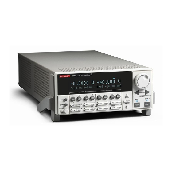
Models 2601, 2611, 2602, 2612, 2635, and 2636 front panel Models 2601, 2611, and 2635 Models 2602, 2612, and 2636 NOTE The Models 2601, 2611, and 2635 have one SourceMeter channel (Channel A), and the Models 2602, 2612, and 2636 have two SourceMeter channels (Channel A and Channel B). - Page 31 Keys 2 Source-measure setup, performance control, and special operation: Top row Models 2601, 2602, 2611, 2612, 2635, and 2636: Channel A selects the source function (V or A) and places cursor in the source field for editing. Channel A cycles through measure functions (V, A, Ω, or W).
- Page 32 Section 1: Getting Started Series 2600 System SourceMeter® Instruments Reference Manual TRIG Triggers readings. MENU Accesses the main menu for saving and recalling setups, selecting a remote interface, line frequency, self-tests, serial number, and beeper control. EXIT Cancels selection and backs out of menu structure. Also used as a LOCAL key to take the unit out of remote.
-
Page 33: Rear Panel Summaries
Series 2600 System SourceMeter® Instruments Reference Manual Section 1: Getting Started Rear panel summaries The rear panels of Models 2601/2611 and Models 2602/2612 are shown in Figure 1-2. The descriptions of the rear panel components follow Figure 1-2. The rear panels of Models 2625 and 2636 are shown in Figure 1-3. - Page 34 Input/output connections for source, sense, and guard. 2 DIGITAL I/O Female DB-25 connector. Fourteen pins for digital input or output, one pin for output enable (2601/2602) or safety interlock (2611/2612); +5V and GND pins are also provided. Use a cable equipped with a male DB-25 connector (Keithley Instruments part number CA-126-1CA).
- Page 35 Series 2600 System SourceMeter® Instruments Reference Manual Section 1: Getting Started Figure 1-3 Models 2635/2636 rear panels Model 2635 WARNING: WARNING: NO INTERNAL OPERATOR SERVICABLE PARTS,SERVICE BY QUALIFIED PERSONNEL ONLY. NO INTERNAL OPERATOR SERVICABLE PARTS,SERVICE BY QUALIFIED PERSONNEL ONLY. SENSE CHANNEL A SENSE GUARD...
- Page 36 PC (Keithley Instruments Model 7009-5). 7. TSP-Link Expansion interface that allows a Series 2600 and other TSP-enabled instruments to trigger and communicate with each other. Use a category 5e or higher LAN crossover cable (Keithley Instruments part number CA-180-3A). 8. Power module Contains the AC line receptacle and power line fuse.
-
Page 37: Cooling Vents
Ground Module 9. Triax connector Channel A and Channel B low noise chassis ground triax connectors. Use only low-noise triax cables such as the Keithley Model 7078-TRX. Connector terminals and associated triax cable connectors are as follows: Table 1-2... -
Page 38: Power-Up
= 60 Fuse replacement A rear panel fuse drawer is located below the AC receptacle (refer to Figure 1-2 for Models 2601/ 2602/2611/2612 and Figure 1-3 for Models 2635/2636). This fuse protects the power line input of the instrument. If the line voltage fuse needs to be replaced, refer to "Line fuse replacement"... -
Page 39: Power-Up Sequence
MENU > BEEPER. Choose one of the following: 1. Unit displays actual model number: 2601, 2602, 2611, 2612, 2635, or 2636. 2. Unit displays actual model number: 2601, 2602, 2611, 2612, 2635, or 2636. 2600S-901-01 Rev. C / January 2008... -
Page 40: Display Modes
This applies to CHANNEL A (SMU A) and CHANNEL B (SMU B). The Models 2601, 2611, and 2635 are a single channel (SMU A). The User State display messages are defined with specific display commands (refer to... -
Page 41: Editing Controls
Complete the following steps to edit the compliance value. Do one of the following: • (Model 2601/2611/2635 and 2602/2612/2636 in single-channel display mode only) Press the LIMIT key. • (Model 2602/2612/2636 dual-channel display mode only) Press LIMIT or CONFIG, then LIMIT to edit the compliance limit. -
Page 42: Menu Navigation
Section 1: Getting Started Series 2600 System SourceMeter® Instruments Reference Manual Menu navigation When the Series 2600 is not in the edit mode (the Edit indicator does not display), the editing controls are used to navigate the Main and Configuration menus (refer to the “menus” topic later in Section 1) to make selections and/or set values. -
Page 43: Menu Types
Series 2600 System SourceMeter® Instruments Reference Manual Section 1: Getting Started Menu types Many aspects of operation are configured through menus. There are two types of menus. Refer to "Menu navigation" topic in this section for more details on using menus. Main menu The main menu is summarized in Table... -
Page 44: Interface Selection
Section 1: Getting Started Series 2600 System SourceMeter® Instruments Reference Manual Menu selection Description Reference LINE-FREQ Configure the line frequency. Section 1 AUTO Automatically selects the line frequency. 50Hz 60Hz SYSTEM-INFO Displays the system information. Section 1 FIRMWARE Displays the version of firmware installed. SERIAL# Displays the serial number of the unit. -
Page 45: To Select The Gpib Interface
Series 2600 System SourceMeter® Instruments Reference Manual Section 1: Getting Started To select the GPIB interface Press MENU > GPIB and then press ENTER. Choose ADDRESS, then press ENTER. Set the GPIB address (0 to 30) and press ENTER. Press EXIT to return to the main menu. To select the RS-232 interface Press MENU >... -
Page 46: Remote Operation Setups
Section 1: Getting Started Series 2600 System SourceMeter® Instruments Reference Manual • Select FACTORY to restore factory defaults, and press ENTER. To select power-on setup: Press the MENU > SETUP > POWERON, and then press ENTER Do one of the following: •... -
Page 47: Table 1-5 Default Settings
Display mode (Models 2602/2612/2636) Dual-channel Filter: Averaging type Repeat Count GPIB address No effect Limit value: Current limit 1A Models (2601/2602/2611/2612) 100mA Models (2635/2636) Voltage limit 20V Models (2635/2636) 40V Models (2601/2602) 200V Models (2611/2612) Measure: Function Voltage I-meter range... -
Page 48: Remote Programming
Table 1-5 (continued) Default settings Sense mode 2-wire Source: Function Voltage Current value Voltage value Current range 100nA Models (2601/2602/2611/2612) 1nA Models (2635/2636) Voltage range 100mV Models (2601/2602) 200mV Models /2611/2612/2635/2636) Speed Normal (1 PLC) Triggering: Trigger-in source Immediate Count Finite This page left blank intentionally. - Page 49 Section 2 TSP Programming In this section: Topic Page Introduction..................Test Script Processor (TSP) ............Run-time environment ..............Queries..................Scripts ................... Named scripts ................Functions..................Scripts that create functions ............Programming overview..............What is a chunk?................What is a script?................Run-time environment ..............
- Page 50 Section 2: TSP Programming Series 2600 System SourceMeter® Instruments Reference Manual Using the expanded system............. 2-33 Source-measure voltage and current ........... 2-33 Read and write to Digital I/O port..........2-33 Display user-defined messages ..........2-34 User scripts ..................2-34 Script examples ................
-
Page 51: Tsp Programming
Keithley Instruments’ Test Script Processor-based instruments can operate as conventional instruments by responding to a sequence of command messages sent by a controller. They are also capable of much more. -
Page 52: Queries
Section 2: TSP Programming Series 2600 System SourceMeter® Instruments Reference Manual When the unit is turned off, the entire run-time environment will be lost. Note that SMU non-volatile reading buffers are not lost. Queries TSP-enabled instruments do not have inherent query commands. Like any other scripting environment the print command and other related print commands are used to generate output. -
Page 53: Functions
Series 2600 System SourceMeter® Instruments Reference Manual Section 2: TSP Programming scripts can be made available simultaneously within the limits of the memory available to the run- time environment. Named scripts are stored as global variables in the run-time environment. Like all other global variables, when the unit is powered off, they are lost. -
Page 54: Programming Overview
Section 2: TSP Programming Series 2600 System SourceMeter® Instruments Reference Manual Programming overview What is a chunk? A chunk is a single programming statement or a sequence of statements that are executed sequentially. There are non-scripted chunks and scripted chunks. Single statement chunk –... -
Page 55: Run-Time Environment
There are two types of scripts: Factory scripts and user scripts. A factory script was created by Keithley Instruments at the factory and stored in non-volatile memory of the Series System 2600 SourceMeter. Factory scripts cannot be removed from non-volatile memory. A user script is... -
Page 56: Tsp Programming Levels
Figure 2-1. Factory scripts (created by Keithley Instruments at the factory) are permanently stored in non-volatile memory of the Series 2600. User-created scripts can also be stored in non-volatile memory. When the Series 2600 is turned on, all user scripts and factory script functions are recalled into the run-time environment from non-volatile memory. -
Page 57: Installing The Test Script Builder Software
Programming model for scripts Installing the Test Script Builder software To install the TSB software, close all programs, place the CD (Keithley Instruments part number: KTS-850) into your CD-ROM drive and follow the on-screen instructions. If your web browser does not start automatically and display a screen with software installation links, open the index.html file... -
Page 58: Rs-232
GPIB cable NOTE To minimize interference caused by electromagnetic radiation, use only shielded GPIB cables. Available shielded cables from Keithley Instruments are the Model 7006 and Model 7007. The GPIB cable connectors are stackable. For additional non-Series 2600 GPIB instruments in the test system, daisy-chain a GPIB cable from one instrument to another. -
Page 59: Using Test Script Builder
Series 2600 System SourceMeter® Instruments Reference Manual Section 2: TSP Programming • Baud rate: 9600 • Data bits: 8 • Parity: None • Flow Control: None The RS-232 settings can be changed from the communications menu. To access the menu, press the MENU key, select COMMUNICATIONS, and then select RS-232. -
Page 60: Project Navigator
For a default installation, follow this menu path to start the Test Script Builder: Start > Programs > Keithley Instruments > Test Script Builder Workspace Launcher – During the initial start-up of TSB, the Workspace Launcher window will be displayed as shown below. -
Page 61: Instrument Console
Series 2600 System SourceMeter® Instruments Reference Manual Section 2: TSP Programming subsequent power-ups, select “Use this as the default and do not ask again.” Click OK to continue start-up. Note: See “Creating a new workspace” later in Section 2 to create additional workspaces. Communications –... - Page 62 Section 2: TSP Programming Series 2600 System SourceMeter® Instruments Reference Manual Figure 2-6 Opening and closing communications 2-14 Return to Section Topics 2600S-901-01 Rev. C / January 2008...
-
Page 63: Creating And Modifying A Script
Series 2600 System SourceMeter® Instruments Reference Manual Section 2: TSP Programming Creating and modifying a script The flowcharts in Figure 2-7 show the basic processes to create and modify a script using the Test Script Builder. The labels (A through G) are used to identify reference links provided after the illustration. - Page 64 Section 2: TSP Programming Series 2600 System SourceMeter® Instruments Reference Manual Figure 2-8 Creating a project folder Writing or modifying a script A script is a list of ICL commands and TSL statements. Figure 2-5 shows a simple example of a script.
- Page 65 Series 2600 System SourceMeter® Instruments Reference Manual Section 2: TSP Programming The toolbar at the top of the Test Script Builder is used to save the displayed script file. As explained in Figure 2-9, the script file can be saved in the same folder and/or saved in a different folder.
- Page 66 Section 2: TSP Programming Series 2600 System SourceMeter® Instruments Reference Manual Figure 2-10 Creating a new script file Renaming a project folder and/or script file When a new project is created, a script file (named “main”) is also created and placed in the Folder.
-
Page 67: Script Launch Configuration
Series 2600 System SourceMeter® Instruments Reference Manual Section 2: TSP Programming Figure 2-11 Renaming a project folder and/or script file Script launch configuration A script is to be loaded into the Series 2600 where it will be executed (run). The launch configuration options include the following: •... - Page 68 Section 2: TSP Programming Series 2600 System SourceMeter® Instruments Reference Manual Reference links for labels A through G shown in Figure 2-12: “Starting Test Script Builder” “Opening communications” “Displaying the launch configuration window” “Selecting a configuration” “Selecting script files and launch order”...
- Page 69 Series 2600 System SourceMeter® Instruments Reference Manual Section 2: TSP Programming Selecting a configuration When a project is created using the Test Script Builder, a Configuration name for the launch is also created. The project name is altered to append “_Script” to it. For example, for a project named “SourceMeasure,”...
-
Page 70: Launching A Script
Section 2: TSP Programming Series 2600 System SourceMeter® Instruments Reference Manual Figure 2-14 Run dialog box (Script Attributes tab) Launching a script After checking and/or changing a launch configuration, the script is launched from the Run dialog box by clicking the Run button shown in Figure 2-13. -
Page 71: Running A Tsp File
Series 2600 System SourceMeter® Instruments Reference Manual Section 2: TSP Programming Running a TSP file A TSP (.tsp) file does not have to be launched (loaded) into the Series 2600 in order to be run. The code for a TSP file can simply be sent to the Series 2600 and executed. The TSP file will not reside in the Series 2600 (it is not saved in volatile or non-volatile memory). -
Page 72: Instrument Console
Section 2: TSP Programming Series 2600 System SourceMeter® Instruments Reference Manual Figure 2-17 Importing a script from memory of the Series 2600 Instrument Console With communications established with the SourceMeter, the Instrument Console is used for the following operations: • Execute chunks, which are individual ICL commands and TSL programming statements. - Page 73 Series 2600 System SourceMeter® Instruments Reference Manual Section 2: TSP Programming An active Instrument Console displays the TSP> prompt. Type in a command after the prompt and press Enter to execute it. For example, type in the following command: TSP>reset () After pressing Enter, the SourceMeter will reset to its default settings.
- Page 74 Instrument – Clicking this menu item opens a submenu to select items that perform the same operations as some of the other toolbar icons. Also included in the menu is the Flash item. The Keithley Instruments Flash Programmer is used to download firmware upgrades into the Series 2600. See “Flash...
- Page 75 The first page of Language Help provides links to the major topics of the help file. Browser View tab When on-line to the internet, this tab serves as a browser for the Keithley Instruments website (www.keithley.com). Bookmarks tab Tasks tab This tab displays bookmarks that are placed in the Script Editor by the user.
- Page 76 Section 2: TSP Programming Series 2600 System SourceMeter® Instruments Reference Manual Figure 2-18 Programming interaction tabs: Problems, Tasks and Command Help 2-28 Return to Section Topics 2600S-901-01 Rev. C / January 2008...
- Page 77 When a firmware upgrade for the Series 2600 becomes available, it can be downloaded from the Keithley Instruments website (www.keithley.com). New or enhanced factory scripts may be included in the upgrade. The file for the firmware upgrade can then be installed in the Series 2600 using the flash programmer.
-
Page 78: File Management Tasks
Section 2: TSP Programming Series 2600 System SourceMeter® Instruments Reference Manual CAUTION External circuitry connected to input/output terminals while attempting a flash upgrade may cause instrument and/or DUT damage. Disconnect input/output terminals before performing a flash upgrade. With communications between the TSB and the SourceMeter opened, the flash programmer can be accessed using the Menu icon as follows: Click Menu icon >... - Page 79 Series 2600 System SourceMeter® Instruments Reference Manual Section 2: TSP Programming Figure 2-20 Workspace Launcher and Select Workspace Directory Importing a project from another workspace A project (along with its script files) can be imported from another workspace folder that resides in your file system.
- Page 80 Section 2: TSP Programming Series 2600 System SourceMeter® Instruments Reference Manual Figure 2-21 Importing a project from another workspace folder Switching workspaces Perform the following steps to switch to another workspace: 1. At the top of TSB, click File on the toolbar to open the file menu and then click Switch Workspace to open the Workspace Launcher (Figure 2-20A).
-
Page 81: Using The Expanded System
Series 2600 System SourceMeter® Instruments Reference Manual Section 2: TSP Programming Figure 2-22 Deleting a project The script file will be deleted from the Project Navigator and will also be deleted from the workspace folder for the project. Deleting a script file To delete a script file from a project, right-click the script file in the Project Navigator and then click Delete in the mouse menu. -
Page 82: Display User-Defined Messages
Section 2: TSP Programming Series 2600 System SourceMeter® Instruments Reference Manual Use the following code fragment to write to one bit of the Digital I/O port. The I/O bit is then read and the state is returned to the PC where it is displayed. -- Writes a “0”... - Page 83 Series 2600 System SourceMeter® Instruments Reference Manual Section 2: TSP Programming NOTE When creating a script using the Test Script Builder, only the chunk is typed in as shown above. See “Using Test Script Builder” earlier in this section for details on creating, loading and running the script. When creating a script using a programming language, shell commands must be included to manage interactions between the host computer and TSP.
-
Page 84: Creating A User Script
Section 2: TSP Programming Series 2600 System SourceMeter® Instruments Reference Manual Table 2-3 Example interactive chunk fragment for a script Script Chunk Fragment (Test Script Builder or User’s Program) --Prompt operator to select channel: chan = display.menu ("Select Channel", "smua smub") if (chan == "smua") then chan = smua if (chan == "smub") then... -
Page 85: Saving A User Script
Series 2600 System SourceMeter® Instruments Reference Manual Section 2: TSP Programming Details on are provided as follows: loadscript loadandrunscript loadscript loadscript name where: is the user-assigned name for the script. name shell command loads the script into the run-time environment. The script can be loadscript assigned a name or it can be left nameless. -
Page 86: Running A User Script
Section 2: TSP Programming Series 2600 System SourceMeter® Instruments Reference Manual test1.save(test2) Running a user script Running the anonymous script There can only be one anonymous script in the run-time environment. If another anonymous script is created and loaded, the previous anonymous script will be removed from the run-time environment. - Page 87 Series 2600 System SourceMeter® Instruments Reference Manual Section 2: TSP Programming NOTE The command sets the loadandrunscript name autorun attribute for that script to “yes.” To cancel autorun, set the autorun attribute to “no” and save the script. Autoexec script One script can be designated as the autoexec script.
-
Page 88: Modifying A User Script
Section 2: TSP Programming Series 2600 System SourceMeter® Instruments Reference Manual After adding a name to the User menu, the script can then be run from the front panel as follows: 1. Press the LOAD key. 2. Select User. 3. Select the user script to run and press the RUN key. Modifying a user script A user script stored in non-volatile memory can be modified by retrieving the script listing for the script. - Page 89 Series 2600 System SourceMeter® Instruments Reference Manual Section 2: TSP Programming The following function retrieves a script listing. The script chunk is returned, along with the shell keywords ( , and loadscript loadandrunscript endscript myscript.list() where: is the user-defined name of the script. myscript Example: Retrieve the listing for a saved script named “test7”:...
-
Page 90: Factory Scripts
Series 2600 System SourceMeter® Instruments Reference Manual Factory scripts A factory script is basically the same as a user script, except a factory script is created by Keithley Instruments at the factory and is permanently stored in non-volatile memory. Factory scripts are... -
Page 91: Differences: Remote Versus Local State
Series 2600 System SourceMeter® Instruments Reference Manual Section 2: TSP Programming script.factory.scripts.name.list() where: is the name of the factory script. name Example: Retrieve the script listing for a factory script named “KIGeneral”: script.factory.scripts.KIGeneral.list() Differences: Remote versus local state The Series 2600 can be in either the local state or the remote state. When in the local state (REM annunciator off), the instrument is operated using the front panel controls. -
Page 92: Memory Considerations For The Runtime Environment
Section 2: TSP Programming Series 2600 System SourceMeter® Instruments Reference Manual The node that receives the command becomes the Master and can control all of the other nodes, which become its Slaves. In a PC-based system, the Master/Slave relationship between nodes can only be dissolved by performing an abort. -
Page 93: Test Script Language (Tsl) Reference
Series 2600 System SourceMeter® Instruments Reference Manual Section 2: TSP Programming Test Script Language (TSL) reference Introduction A script is a program that the Test Script Processor (TSP) executes. A script is written using the Test Script Language (TSL). TSL is an efficient language, with simple syntax and extensible ©... -
Page 94: Operators
Section 2: TSP Programming Series 2600 System SourceMeter® Instruments Reference Manual Operators Arithmetic Operators: Relational Operators: Logical Operators: (addition) (less than) < (subtraction) (greater than) > (multiplication) (less than or equal) <= (division) (greater than or equal) >= (negation) (not equal) (equal) Functions TSL allows you to define functions. -
Page 95: Tables/Arrays
Series 2600 System SourceMeter® Instruments Reference Manual Section 2: TSP Programming print(ratio) Output of code above: 0.66666 Tables/arrays TSL makes extensive use of the data type “table,” which is essentially a very flexible array-like data type. Define a table: -- A table with four elements, which are numbers. atable = {1, 2, 3, 4} Let's print it: -- Tables are indexed on one, NOT zero. -
Page 96: Precedence
Section 2: TSP Programming Series 2600 System SourceMeter® Instruments Reference Manual circle = {clr = "red", diam = 1, setdiam = function(d) circle["diam"]=d end} -- Index using a string; print the clr property. print(circle["clr"]) -- Index using a string; print the diam property. print(circle["diam"]) -- Change the diam element by calling setdiam method. -
Page 97: Concatenation
Series 2600 System SourceMeter® Instruments Reference Manual Section 2: TSP Programming print(nil and 13) print(false and 13) print(4 or 5) print(false or 5) Output of code above: false Both and and or use short-cut evaluation, that is, they evaluate their second operand only when necessary. -
Page 98: Branching
Section 2: TSP Programming Series 2600 System SourceMeter® Instruments Reference Manual Branching TSL uses the “if” keyword to do conditional branching. -------------------------------- IF blocks ------------------------ -- Zero IS true! This is a contrast to C where 0 evaluates if 0 then false. -
Page 99: Loop Control
Series 2600 System SourceMeter® Instruments Reference Manual Section 2: TSP Programming ' if ' expression 4 was false. x is not equal to 10, and y is not less than 2. Loop control TSL has familiar constructs for doing things repetitively and/or until an expression evaluates to false. - Page 100 Section 2: TSP Programming Series 2600 System SourceMeter® Instruments Reference Manual element = element + 1 until not list[element] Output of code above: Counting from one to three: 1 One 2 Two 3 Three Counting from one to four, in steps of two: 1 One 3 Three Counting elements in list...
-
Page 101: Standard Libraries
Series 2600 System SourceMeter® Instruments Reference Manual Section 2: TSP Programming Standard libraries In addition to the standard programming constructs above, TSL includes standard libraries that contain useful functions for string manipulation, mathematics, etc. TSL also includes instrument control extension libraries. These libraries provide programming interfaces to the instrumentation accessible by the TSP. - Page 102 Section 2: TSP Programming Series 2600 System SourceMeter® Instruments Reference Manual String library functions This library provides generic functions for string manipulation, such as finding and extracting substrings. When indexing a string in TSL, the first character is at position 1 (not 0 as in ANSI C). Indices may be negative and are interpreted as indexing backwards, from the end of the string.
- Page 103 Series 2600 System SourceMeter® Instruments Reference Manual Section 2: TSP Programming Returns the largest floating-point number not greater than x math.floor(x) whose value is an exact mathematical integer. Returns the natural logarithm function of x. math.log(x) Returns the base-10 logarithm function of x. math.log10(x) Returns the maximum value of its numeric argument(s).
- Page 104 Section 2: TSP Programming Series 2600 System SourceMeter® Instruments Reference Manual This page left blank intentionally. 2-56 Return to Section Topics 2600S-901-01 Rev. C / January 2008...
-
Page 105: Dut Test Connections
Section 3 DUT Test Connections In this section: Topic Page Input/output connectors ..............Input/output LO and chassis ground..........Sensing methods................2-wire local sensing............... 4-wire remote sensing ..............Sense mode selection ..............Contact check connections .............. Multiple SMU connections ..............3-10 Guarding and shielding .............. -
Page 106: Input/Output Connectors
DUTs (devices under test). The Model 2602/2612 uses two connectors as shown in Figure 3-1 (one for each source-measure unit (SMU) channel). The Model 2601/2611 has only one connector for a single SMU. Models 2635 and 2636 use triax connectors as shown in Figure 3-2. -
Page 107: Input/Output Lo And Chassis Ground
Series 2600 System SourceMeter® Instruments Reference Manual Section 3: DUT Test Connections Figure 3-1 2602/2612 input/output connectors Channel B Channel A CHANNEL A CHANNEL B Captive screw (2 per terminal block) HI = Input/Output HI Each terminal block uses two captive S HI = Sense HI screws to secure it to the rear panel. - Page 108 Section 3: DUT Test Connections Series 2600 System SourceMeter® Instruments Reference Manual As shown, there is a low-noise chassis ground banana jack that can be used as a common signal ground point for Input/Output LOs. This low-noise signal ground banana jack is connected to the chassis through a Frequency Variable Resistor (FVR).
-
Page 109: Sensing Methods
Series 2600 System SourceMeter® Instruments Reference Manual Section 3: DUT Test Connections Figure 3-4 Model 2602/2612 Low-Noise Chassis Ground Banana Jack and Chassis Screw Model 2636 Channel B LO Channel A LO Floating Floating Channel A LO Channel B LO Chassis GND WARNING When connecting to the model 2611, 2612, 2635 and 2636 SMU... -
Page 110: 2-Wire Local Sensing
Section 3: DUT Test Connections Series 2600 System SourceMeter® Instruments Reference Manual 2-wire local sensing Two-wire local sensing (as shown in Figure 3-5) can be used for the following source-measure conditions: • Sourcing and measuring current. • Sourcing and/or measuring voltage in high impedance (>1kΩ) test circuits. Figure 3-5 Model 2602/2612 two-wire connections (local sensing) -
Page 111: 4-Wire Remote Sensing
Series 2600 System SourceMeter® Instruments Reference Manual Section 3: DUT Test Connections 4-wire remote sensing When sourcing and/or measuring voltage in a low-impedance test circuit (see Figure 3-6), there can be errors associated with IR drops in the test leads. Voltage source and measure accuracy are optimized by using 4-wire remote sense connections. -
Page 112: Table 3-1 Selecting The Sense Mode From The Front Panel
1. All Model 2611/2612 System SourceMeters manufactured by Keithley Instruments support the contact check function. Models 2635 and 2636 do not support the contact check function. Only Models 2601/2602 with firmware Revision 1.1.0 or later and source measure unit (SMU) hardware Revision E or later support the contact check function. To determine the firmware and SMU hardware revisions, inspect the data returned by the print(localnode.info()) command. -
Page 113: Contact Check Connections
Series 2600 System SourceMeter® Instruments Reference Manual Section 3: DUT Test Connections Figure 3-7 Contact check connections 2600S-901-01 Rev. C / January 2008 Return to Section Topics... -
Page 114: Multiple Smu Connections
Section 3: DUT Test Connections Series 2600 System SourceMeter® Instruments Reference Manual Multiple SMU connections Figure 3-8 shows how to use two SMUs to test a 3-terminal device, such as an N-channel JFET. A typical application is for SMU B to source a range of gate voltages, while SMU A sources voltage to power the device and measures current at each gate voltage. - Page 115 Series 2600 System SourceMeter® Instruments Reference Manual Section 3: DUT Test Connections Figure 3-9 Three SMUs connected to a 3-terminal device Model 2636, three SMUs connected to a 3-terminal device (local sensing, non-floating) 2600S-901-01 Rev. C / January 2008 Return to Section Topics 3-11...
-
Page 116: Guarding And Shielding
Section 3: DUT Test Connections Series 2600 System SourceMeter® Instruments Reference Manual Guarding and shielding Source-measure performance and safety are optimized with the effective use of guarding and shielding (noise and safety shields). Guarding A driven guard is always enabled and provides a buffered voltage that is at the same level as the input/output HI voltage. -
Page 117: Noise Shield
Series 2600 System SourceMeter® Instruments Reference Manual Section 3: DUT Test Connections Figure 3-11 Model 2636 high-impedance guarding (floating) Sense Sense CHANNEL A Guard Guard Sense CHANNEL B Sense B LO A LO Floating Guard >1GΩ Figure 3-12 Model 2636 High-impedance guarding (non-floating) Noise shield A noise shield (see Figure... - Page 118 Section 3: DUT Test Connections Series 2600 System SourceMeter® Instruments Reference Manual Figure 3-13 Models 2602 and 2612 noise shield Model 2636 noise shield (non-floating) 3-14 Return to Section Topics 2600S-901-01 Rev. C / January 2008...
- Page 119 Series 2600 System SourceMeter® Instruments Reference Manual Section 3: DUT Test Connections Figure 3-14 Model 2636 noise shield (non-floating) Figure 3-15 Model 2636 noise shield (floating) 2600S-901-01 Rev. C / January 2008 Return to Section Topics 3-15...
-
Page 120: Figure 3-16
Model 2601/2602 safety shield The maximum output voltage for a Model 2601/2602 channel is 40V, which is considered a non- hazardous level. However, using two or more Model 2601/2602 voltage sources in a series configuration can cause test circuit voltage to exceed 42V. -
Page 121: Figure 3-18
Figure 3-18 Safety shield for Models 2611/2612/2635/2636 hazardous voltage (200V maximum) SMU 2611/ 2612/2635/ 2636 Figure 3-19 Model 2601/2602-1 connections for test circuit shown in Figure 3-18 2600S-901-01 Rev. C / January 2008 Return to Section Topics 3-17... -
Page 122: Using Shielding And Guarding Together
The guard shields are connected to the driven guard (G) of the SMU. The noise shield is connected to SMU LO. The safety shield is connected to the chassis and to a safety earth ground. Figure 3-21 Model 2601/2602-1 connections for noise shield, safety shield, and guarding 3-18 Return to Section Topics 2600S-901-01 Rev. -
Page 123: Test Fixture
Series 2600 System SourceMeter® Instruments Reference Manual Section 3: DUT Test Connections Figure 3-22 Model 2636 connections for noise shield, safety shield, and guarding Test fixture A test fixture can be used for an external test circuit. The test fixture can be a metal or nonmetallic enclosure, and is typically equipped with a lid. -
Page 124: Floating A Smu
The output enable pin on the digital I/O port on the Models 2601 and2602 SourceMeter is not suitable for control of safety circuits and should not be used to control a safety interlock. -
Page 125: Figure 3-23 Floating The Series 2600
Series 2600 System SourceMeter® Instruments Reference Manual Section 3: DUT Test Connections The maximum floating (common mode) voltage for a SMU is ±250V. WARNING Exceeding this level may cause damage to the instrument and create a shock hazard. Using an external source to float a SMU could create a shock hazard in the test circuit. - Page 126 Section 3: DUT Test Connections Series 2600 System SourceMeter® Instruments Reference Manual Figure 3-24 Model 2601/2602-1 SMU connections for the floating configuration shown in Figure 3-23 Model 2636 SMU connections for the floating configuration shown in Figure 3-23 3-22 Return to Section Topics 2600S-901-01 Rev.
-
Page 127: Output-Off States
Series 2600 System SourceMeter® Instruments Reference Manual Section 3: DUT Test Connections Output-off states When a SMU is turned off, it may not be completely isolated from the external circuit that it is connected to. There are three output-off states for a Series 2600 SMU: Normal, High Impedance or zero. - Page 128 = smuX.OUTPUT_HIGH_Z Selects high-impedance output- off state. smuX.source.offmode = smuX.OUTPUT_ZERO Selects zero output-off state. * Model 2601/2611/2635: smuX = smua, Model 2602/2612/2636: smuX = smua (Channel A) or smub (Channel B). 3-24 Return to Section Topics 2600S-901-01 Rev. C / January 2008...
-
Page 129: Figure 4-4 Contact Check Measurements
Section 4 Basic Operation In this section: Topic Page Overview..................... Operation overview ................Source-measure capabilities............Compliance limit................Setting the compliance limit ............Basic circuit configurations............Operation considerations ..............Warm-up ..................Auto zero..................NPLC caching ................Basic source-measure procedure............ Front panel source-measure procedure........ -
Page 130: Overview
Section 4: Basic Operation Series 2600 System SourceMeter® Instruments Reference Manual Overview The documentation in this section provides basic operating instructions for the Keithley ® Instruments Series 2600 System SourceMeter and includes the following: • "Operation overview" • "Operation considerations"... -
Page 131: Compliance Limit
Series 2600 System SourceMeter® Instruments Reference Manual Section 4: Basic Operation Table 4-1 Source-measure capabilities Model 2601/2602 Model 2611/2612 Model 2635/2636 Range Source Measure Range Source Measure Range Source Measure 100mV ±101mV ±102mV 200mV ±202mV ±204mV 200mV +/-202mV +/-204mV ±1.01V ±1.02V... -
Page 132: Setting The Compliance Limit
1.5A 200V 100mA 1.5A *smuX = smua for the Model 2601/2611/2635; smuX = smua (Channel A) or smub (Channel B) for the Model 2602/2612/2636. Setting the compliance limit Front panel compliance limit Set the compliance limit from the front panel as follows: For the Model 2601/2611/2635 or the Model 2602/2612/2636 single-channel display mode, press the LIMIT key to directly access compliance editing. -
Page 133: Basic Circuit Configurations
Test if in compliance (1 = in compliance; 0 = not in compliance). *smuX = smua for the Model 2601/2611/2635; smuX = smua (Channel A) or smub (Channel B) for the Model 2602/2612/2636. Basic circuit configurations The fundamental source-measure configurations for the SourceMeter are shown in Figure 4-1. -
Page 134: Table 4-4 Auto Zero Settings
Section 4: Basic Operation Series 2600 System SourceMeter® Instruments Reference Manual Operation considerations The following paragraphs discuss the warm-up period and auto zero. Warm-up The SourceMeter must be turned on and allowed to warm up for at least two hours to achieve rated accuracies. - Page 135 Force ref and zero with each mea- surement. *smuX = smua for the Model 2601/2611/2635; smuX = smua (Channel A) or smub (Channel B) for the Model 2602/2612/2636. **Old NPLC cache values will be used when auto zero is disabled. See "NPLC caching"...
-
Page 136: Basic Source-Measure Procedure
Step 2: Set compliance limit. Perform the following steps to edit the compliance limit value: For the Model 2601/2611/2635 or the Model 2602/2612/2636 single-channel display mode, press the LIMIT key. For the Model 2602/2612/2636 dual-channel display mode, press CONFIG then LIMIT, then select CURRENT or VOLTAGE. -
Page 137: Remote Source-Measure Procedure
Series 2600 System SourceMeter® Instruments Reference Manual Section 4: Basic Operation • When measuring the source (i.e., Source V Measure V), you cannot select the measurement range using the RANGE keys. The selected source range determines the measurement range. • When not measuring the source (i.e., Source V Measure I), measurement range selection can be done manually or automatically. -
Page 138: Table 4-6 Basic Source-Measure Commands
Local sense (2-wire). smuX.sense = smuX.SENSE_REMOTE Remote sense (4-wire). * smuX = smua for the Model 2601/2611/2635; smuX = smua (Channel A) or smub (Channel B) for the Model 2602/2612/2636. Requesting readings You can request readings by including the appropriate measurement command as the argument for the print command. -
Page 139: Measure Only
Series 2600 System SourceMeter® Instruments Reference Manual Section 4: Basic Operation smua.source.levelv = 5 --Set voltage source to 5V. smua.source.limiti = 10e-3 --Set current limit to 10mA. smua.measure.rangei = 10e-3 --Set current range to 10mA. smua.source.output =smua.OUTPUT_ON --Turn on output. print(smua.measure.i()) --Request current reading. -
Page 140: Sink Operation
Section 4: Basic Operation Series 2600 System SourceMeter® Instruments Reference Manual Sink operation When operating as a sink (V and I have opposite polarity), the SourceMeter is dissipating power rather than sourcing it. An external source (i.e., battery) or an energy storage device (i.e., capacitor) can force operation into the sink region. -
Page 141: Ohms Sensing
Series 2600 System SourceMeter® Instruments Reference Manual Section 4: Basic Operation WARNING Hazardous voltages may be present on the output and guard terminals. To prevent electrical shock that could cause injury or death, NEVER make or break connections to the Series 2600 while the output is on. -
Page 142: Sense Selection
Section 4: Basic Operation Series 2600 System SourceMeter® Instruments Reference Manual Figure 4-2 2-wire resistance sensing Figure 4-3 4-wire resistance sensing Sense selection Front panel sense selection To select sensing mode: Press the CONFIG key then press MEAS. Choose V-MEAS, and then press ENTER or the Rotary Knob. -
Page 143: Remote Ohms Programming
Series 2600 System SourceMeter® Instruments Reference Manual Section 4: Basic Operation Select SENSE-MODE, then press ENTER. Choose 2-WIRE or 4-WIRE, as desired, and then press ENTER or the Rotary Knob. Remote sense selection Use the smuX.sense command to control sense selection by remote. For example, send this command to enable 4-wire sensing: smua.sense = smua.SENSE_REMOTE Table 4-6... -
Page 144: Power Measurements
Section 4: Basic Operation Series 2600 System SourceMeter® Instruments Reference Manual Power measurements Power calculations Power readings are calculated from the sourced and measured current or voltage as follows: × P = V Where: P is the calculated power V is the sourced or measured voltage I is the measured or sourced current Basic power measurement procedure Perform the following steps to perform power measurements. -
Page 145: Overview
1. All Model 2611/2612 System SourceMeters manufactured by Keithley Instruments support the contact check function. Models 2635 and 2636 do not support the contact check function. Only Models 2601/2602 with firmware Revision 1.1.0 or later and source measure unit (SMU) hardware Revision E or later support the contact check function. To determine the firmware and SMU hardware revisions, inspect the data returned by the print(localnode.info()) command. -
Page 146: Contact Check Commands
1 or smuX.CONTACT_MEDIUM 2 or smuX.CONTACT_SLOW smuX.contact.threshold = rvalue Resistance threshold for the contact check function. *smuX = smua for the Model 2601/2611; smuX = smua (Channel A) or smub (Channel B) for the Model 2602/2612. Figure 4-4 Contact check measurements... -
Page 147: Contact Check Programming Example
Series 2600 System SourceMeter® Instruments Reference Manual Section 4: Basic Operation Contact check programming example The command sequence for a typical contact measurement is shown below. These commands set the contact check speed to fast and the threshold to 10Ω. A contact check measurement against the threshold is then made. - Page 148 Section 4: Basic Operation Series 2600 System SourceMeter® Instruments Reference Manual This page left blank intentionally. 4-20 Return to Section Topics 2600S-901-01 Rev. C / January 2008...
-
Page 149: Table 5-2 Staircase Sweep Functions
Section 5 Sweep Operation In this section: Topic Page Overview..................... Section overview ................Sweep overview ................Sweep characteristics ............... Linear staircase sweeps..............Logarithmic staircase sweeps ............Pulse sweeps ................Custom (list) sweeps ..............Sweep measurement storage ............Sweep functions ................Staircase sweep functions............. -
Page 150: Overview
® As shown in Figure 5-1, the Keithley Instruments Series 2600 System SourceMeter can generate several types of sweeps using the factory sweep scripts. Linear staircase sweep – With this sweep type, the voltage or current increases or decreases in specific steps, beginning with a start current and ending with a stop current. -
Page 151: Sweep Characteristics
Series 2600 System SourceMeter® Instruments Reference Manual Section 5: Sweep Operation Figure 5-1 Comparison of staircase sweep types Sweep characteristics Linear staircase sweeps As shown in Figure 5-2, this sweep type steps from a start voltage or current value to an ending (stop) value. -
Page 152: Logarithmic Staircase Sweeps
Section 5: Sweep Operation Series 2600 System SourceMeter® Instruments Reference Manual Figure 5-2 Linear staircase sweep Logarithmic staircase sweeps This sweep is similar to the linear staircase sweep. The steps, however, are done on a logarithmic scale as shown in the example sweep in Figure 5-3. -
Page 153: Figure 5-3 Logarithmic Staircase Sweep (1V To 10V, Five Steps)
Series 2600 System SourceMeter® Instruments Reference Manual Section 5: Sweep Operation Figure 5-3 Logarithmic staircase sweep (1V to 10V, five steps) The programmable parameters for a log sweep include the source function, channel, start and stop levels, delay (settling time), and the number of measurement points for the sweep. The specified start, stop, and points parameters determine the logarithmic step size for the sweep. -
Page 154: Figure 5-4 Pulse Sweep Example
Section 5: Sweep Operation Series 2600 System SourceMeter® Instruments Reference Manual When this sweep starts, the output will go to the start level (1V) and sweep through the symmetrical log points. The time duration before each measurement at each step is determined by the measurement delay interval. -
Page 155: Sweep Measurement Storage
Functions to perform staircase, pulse, and custom sweeps are discussed below. See Section 13 this manual for details on using factory scripts. NOTE Visit www.keithley.com for additional available user scripts for various tests. 2600S-901-01 Rev. C / January 2008 Return to... -
Page 156: Staircase Sweep Functions
Section 5: Sweep Operation Series 2600 System SourceMeter® Instruments Reference Manual Staircase sweep functions Functions for linear and logarithmic staircase sweeps are listed in Table 5-2. Table 5-2 Staircase sweep functions Command Description Define linear source current sweep: SweepILinMeasureV(smu, starti, stopi, stime, points) Smu: smua for channel A or smub for channel B. -
Page 157: Figure 5-2 Linear Staircase Sweep
Series 2600 System SourceMeter® Instruments Reference Manual Section 5: Sweep Operation Custom sweep functions Functions for list (custom) sweeps are listed in Table 5-4. Table 5-4 Custom sweep functions Command Description Define current list sweep: SweepIListMeasureV(smu, ilist, stime, Smu: smua for channel A or smub for channel B. points) List of current values in amps. - Page 158 Section 5: Sweep Operation Series 2600 System SourceMeter® Instruments Reference Manual Linear staircase sweep example Configure source functions. Examples – The following commands restore defaults and set the compliance to 1V: -- Restore Series 2600 defaults. smua.reset() -- Set compliance to 1V. smua.source.limitv = 1 Configure and execute the sweep.
- Page 159 Series 2600 System SourceMeter® Instruments Reference Manual Section 5: Sweep Operation Custom sweep example Configure source functions Examples – The following commands restore defaults and set the compliance to 10mA: -- Restore Series 2600 defaults. smua.reset() -- Set compliance to 10mA. smua.source.limiti = 10e-3 Configure and execute the sweep.
- Page 160 Section 5: Sweep Operation Series 2600 System SourceMeter® Instruments Reference Manual This page left blank intentionally. 5-12 Return to Section Topics 2600S-901-01 Rev. C / January 2008...
-
Page 161: Range, Digits, Speed, Rel, And Filters
Section 6 Range, Digits, Speed, Rel, and Filters In this section: Topic Page Overview..................... Range....................Available ranges................Maximum source values and readings.......... Ranging limitations ................ Manual ranging ................Auto ranging .................. Low range limits ................Range considerations ..............Range programming .............. -
Page 162: Overview
This usually happens when a change occurs such as selecting a different range. Available ranges Table 6-1 lists the available source and measurement ranges for the Keithley Instruments Series ® 2600 System SourceMeters Table 6-1... -
Page 163: Maximum Source Values And Readings
Note, however, that the instrument will auto range at 100% of the range. Ranging limitations • Model 2601/2602: With the 40V V-Source range selected, the highest current measurement range is 1A. With the 3A I-Source range selected, the highest voltage measurement range is 6V. -
Page 164: Range Considerations
However, the setting for the voltage measure range is retained and used when the source function is changed to current, and the present voltage measurement range will be used. 2601/2602 Example: smua.source.func = smua.OUTPUT_DCVOLTS smua.source.rangev = 1 smua.measure.rangev = 6... -
Page 165: Table 6-2 Range Commands
Select manual current source range. smuX.source.rangev = rangeval Select manual voltage source range. * smuX = smua for the Model 2601/2611; smuX = smua (Channel A) or smub (Channel B) for the Model 2602/2612. ** See Table 6-1 for measure ranges. -
Page 166: Table 6-3 Digits Commands
= display.DIGITS_5_5 Set display to 5.5 digits. display.smuX.digits = display.DIGITS_6_5 Set display to 6.5 digits. 1. smuX = smua for the Model 2601/2611/2635; smuX = smua (Channel A) or smub (Channel B) for the Model 2602/2612/2636. Digits programming example smua.reset() --Restore Series 2600 defaults. -
Page 167: Table 6-4 Speed Command
= nplc Set speed (nplc = 0.001 to 25). 1. smuX = smua for the Model 2601/2611/2635; smuX = smua (Channel A) or smub (Channel B) for the Model 2602/2612/2636. 2. The speed setting is global and affects all measurement functions. -
Page 168: Rel
Section 6: Range, Digits, Speed, Rel, and Filters Series 2600 System SourceMeter® Instruments Reference Manual The rel (relative) feature can be used to null offsets or subtract a baseline reading from present and future readings. With REL enabled, subsequent readings will be the difference between the actual input value and the rel value as follows: Displayed Reading = Actual Input - Rel Value Once a rel value is established for a measurement function, the value is the same for all ranges. -
Page 169: Table 6-5 Rel Commands
= smuX.REL_ON Enable resistance rel. smuX.measure.rel.enablev = smuX.REL_ON Enable voltage rel. * smuX = smua for the Model 2601/2611; smuX = smua (Channel A) or smub (Channel B) for the Model 2602/2612. Rel programming example smua.reset() --Restore Series 2600 defaults. -
Page 170: Filters
Filter type and count is configured from the filter configuration menu. The configured filter is the same for all measurement functions. Filter configuration menu for Models 2601, 2601, 2611, and 2612 Press CONFIG and then FILTER to display the filter configuration menu: •... -
Page 171: Response Time
Series 2600 System SourceMeter® Instruments Reference Manual Section 6: Range, Digits, Speed, Rel, and Filters Filter configuration menu for Models 2635 and 2636 Press CONFIG and then FILTER to display the filter configuration menu: • TYPE - Use this menu item to select filter type (AVERAGE or MEDIAN) •... - Page 172 Section 6: Range, Digits, Speed, Rel, and Filters Series 2600 System SourceMeter® Instruments Reference Manual Figure 6-1 Moving average and repeating filters 6-12 Return to Section Topics 2600S-901-01 Rev. C / January 2008...
-
Page 173: Table 6-6 Filter Commands
= smuX.FILTER_MOVING_AVG Select repeat filter type. smuX.measure.filter.type = smuX.FILTER_REPEAT_AVG * smuX = smua for the Model 2601/2611; smuX = smua (Channel A) or smub (Channel B) for the Model 2602/2612. Filter programming example The example below programs filter aspects as follows: •... - Page 174 Section 6: Range, Digits, Speed, Rel, and Filters Series 2600 System SourceMeter® Instruments Reference Manual This page left blank intentionally. 6-14 Return to Section Topics 2600S-901-01 Rev. C / January 2008...
-
Page 175: Buffer (Data Store)
Section 7 Buffer (Data Store) In this section: Topic Page Overview..................... Data store overview................Front panel data store ............... Buffer configuration ............... Storing readings ................Recalling readings................. Remote data store ................Data store commands ..............Reading buffers ................Time and date values .............. -
Page 176: Overview
"Remote data store" Data store overview ® The Keithley Instruments Series 2600 System SourceMeter has two buffers per channel that can store from 1 to more than 100,000 readings. The instrument can store the readings that are displayed during the storage process. Each buffer reading is numbered and can also include the source value and a time stamp. -
Page 177: Storing Readings
• ELEMENTS: Enable (ON) or disable (OFF) data storage elements; SRC-VAL (source value) or TSTAMP (time stamp). NOTE Model 2601/2611/2635 buffer configuration menu items are the same as covered above except for channel selection. Storing readings You can append measurements to the reading buffer or override existing measurements in the reading buffer. -
Page 178: Table 7-1 Data Store Commands
Print numbers with selected buffer format: v1 … vn (Numbers to print). 1. smuX = smua for the Model 2601/2611/2635; smuX = smua (Channel A) or smub (Channel B) for the Model 2602/2612/2636. 2. rbuffer, ibuffer, and vbuffer = smuX.nvbuffer1 or smuX.nvbuffer2. -
Page 179: Reading Buffers
Series 2600 System SourceMeter® Instruments Reference Manual Section 7: Buffer (Data Store) Reading buffers Readings can be obtained in multiple ways including synchronous or overlapped. Furthermore, the routines that make single point measurements can be configured to make multiple measurements where one would ordinarily be made. -
Page 180: Table 7-2 Buffer Storage Control Attributes
Section 7: Buffer (Data Store) Series 2600 System SourceMeter® Instruments Reference Manual Table 7-2 Buffer storage control attributes Storage attribute Description The append modes are either off or on. When the append mode is off, a new appendmode measurement to this buffer will overwrite the previous contents. When the append mode is on, the first new measurement will be stored at what was formerly rb[n+1]. -
Page 181: Table 7-6 Recall Attributes
Series 2600 System SourceMeter® Instruments Reference Manual Section 7: Buffer (Data Store) Similarly, the following would return 100 Channel A source values from buffer 1: printbuffer(1, 100, smua.nvbuffer1.sourcevalues) Note that readings is the default reading attribute and can be omitted. Thus, the following would also return 100 Channel A readings from buffer 1: printbuffer(1, 100, smua.nvbuffer1) Table 7-6... -
Page 182: Table 7-7 Buffer Status Bits
Section 7: Buffer (Data Store) Series 2600 System SourceMeter® Instruments Reference Manual Buffer status The buffer reading status attribute can include the status information as a numeric value shown in Table 7-7. To access status information, send the following command: stat_info = smua.nvbuffer1.statuses[2] Table 7-7 Buffer status bits... -
Page 183: Buffer Programming Examples
Series 2600 System SourceMeter® Instruments Reference Manual Section 7: Buffer (Data Store) Buffer programming examples Defined buffer example The listing below shows a programming example for storing data using the pre-defined Buffer 1 for Channel A. The SourceMeter loops for voltages from 0.01V to 1V with 0.01V steps (essentially performing a staircase sweep), stores 100 current readings and source values in Buffer 1, and then recalls all 100 readings and source values. - Page 184 Section 7: Buffer (Data Store) Series 2600 System SourceMeter® Instruments Reference Manual Dual buffer example The listing below shows a programming example for storing both current and voltage readings using buffer 1 for current and buffer 2 to store voltage readings. The SourceMeter stores 100 current and voltage readings and then recalls all 100 sets of readings.
- Page 185 Series 2600 System SourceMeter® Instruments Reference Manual Section 7: Buffer (Data Store) Dynamically allocated buffer example The listing below shows a programming example for storing data using an allocated buffer called mybuffer for Channel A. The SourceMeter stores 100 current readings in mybuffer and then recalls all the readings.
- Page 186 Section 7: Buffer (Data Store) Series 2600 System SourceMeter® Instruments Reference Manual This page left blank intentionally. 7-12 Return to Section Topics 2600S-901-01 Rev. C / January 2008...
-
Page 187: Source-Measure Concepts
Section 8 Source-Measure Concepts In this section: Topic Page Overview ..................... Compliance limit ................Maximum compliance..............Compliance principles ..............Sweep waveforms................Staircase sweeps................Pulse sweeps ................Overheating protection ..............Power equations to avoid overheating .......... Operating boundaries ............... Source or sink ................ -
Page 188: Compliance Limit
"Pulse concepts" Compliance limit ® When sourcing voltage, the Keithley Instruments Series 2600 System SourceMeter can be set to limit current. Conversely, when sourcing current, the SourceMeter can be set to limit voltage. The SourceMeter output will not exceed the compliance limit, except for the condition described in "Compliance limit"... -
Page 189: Compliance Principles
Series 2600 System SourceMeter® Instruments Reference Manual Section 8: Source-Measure Concepts Compliance principles Compliance acts as a clamp. If the output reaches the compliance value, the SourceMeter will attempt to prevent the output from exceeding that value. This action implies that the source will switch from a V-source to an I-source (or from an I-source to a V-source) when in compliance. -
Page 190: Figure 8-2 Pulse Sweep Example
Section 8: Source-Measure Concepts Series 2600 System SourceMeter® Instruments Reference Manual Pulse sweeps The Series 2600 can also perform the following pulse sweeps: • Fixed voltage pulse • Fixed current pulse These sweeps are similar to those discussed above, except the source level at each sweep step is a pulse instead of a constant level. - Page 191 Series 2600 System SourceMeter® Instruments Reference Manual Section 8: Source-Measure Concepts • High power pulse operation is not being used. However, if any one of these is false, the SourceMeter may overheat if operated in a manner that exceeds the calculated maximum duty cycle, DC The maximum duty cycle equation is derived from the power equation below by solving for DC The general power equation describes how much power a SourceMeter channel can source and/ or sink before the total power cannot be fully dissipated by the SourceMeter cooling system.
-
Page 192: Table 8-2 Model 2601/2602 Maximum Duty Cycle Equation Constants
SourceMeter to overheat. However, if the calculation yields a number < 10%, the calculated duty cycle should not be exceeded by more than 0.5% to avoid potential overheating. Table 8-2 Model 2601/2602 Maximum Duty Cycle equation constants Constant 100mV range 1V range... -
Page 193: Operating Boundaries
Series 2600 System SourceMeter® Instruments Reference Manual Section 8: Source-Measure Concepts Assuming the 20V range will be used to measure the voltage: 5 ( ) ) 0 ( ) 56 20 – – – ≤ × --------------------------------------------------------------- - 5 ( ) ) 1.5 –... -
Page 194: Continuous Power Operating Boundaries
Section 8: Source-Measure Concepts Series 2600 System SourceMeter® Instruments Reference Manual Continuous power operating boundaries Model 2601/2602 continuous power operating boundaries The general operating boundaries for Model 2601/2602 continuous power output are shown in Figure 8-3 (for derating factors, see "General SourceMeter power equation", described earlier in... -
Page 195: I-Source Operating Boundaries
Operation in the other three quadrants is similar. Figure 8-5A shows the output characteristics for the I-Source. As shown, the Model 2601/2602 SourceMeter can output up to 1.01A at 40V, or 3.03A at 6V. Note that when sourcing more than 1.01A, voltage is limited to 6V. - Page 196 Section 8: Source-Measure Concepts Series 2600 System SourceMeter® Instruments Reference Manual Figure 8-5 Model 2601/2602 I-Source boundaries 8-10 Return to Section Topics 2600S-901-01 Rev. C / January 2008...
- Page 197 Series 2600 System SourceMeter® Instruments Reference Manual Section 8: Source-Measure Concepts Model 2611/2612/2635/2636 I-Source operating boundaries Figure 8-6 shows the operating boundaries for the I-Source. Only the first quadrant of operation is covered. Operation in the other three quadrants is similar. Figure 8-6A shows the output characteristics for the I-Source.
- Page 198 Section 8: Source-Measure Concepts Series 2600 System SourceMeter® Instruments Reference Manual Load considerations The boundaries the SourceMeter operates in depends on the load (DUT) that is connected to its output. Figure 8-7 shows operation examples for resistive loads that are 50Ω and 200Ω, respectively.
-
Page 199: V-Source Operating Boundaries
Operation in the other three quadrants is similar. Figure 8-8A shows the output characteristics for the V-Source. As shown, the Model 2601/2602 SourceMeter can output up to 6.06V at 3A, or 40.4V at 1A. Note that when sourcing more than 6.06V, current is limited to 1A. - Page 200 Section 8: Source-Measure Concepts Series 2600 System SourceMeter® Instruments Reference Manual Model 2611/2612/2635/2636 V-Source operating boundaries Figure 8-9 shows the operating boundaries for the V-Source. Only the first quadrant of operation is covered. Operation in the other three quadrants is similar. Figure 8-9A shows the output characteristics for the V-Source.
- Page 201 Series 2600 System SourceMeter® Instruments Reference Manual Section 8: Source-Measure Concepts Load considerations The boundaries the SourceMeter operates in depends on the load (DUT) that is connected to the output. Figure 8-10 shows operation examples for resistive loads that are 2kΩ and 800Ω, respectively.
-
Page 202: Figure 8-11 Source I Configuration
Section 8: Source-Measure Concepts Series 2600 System SourceMeter® Instruments Reference Manual Source I measure I, source V measure V The SourceMeter can measure the function it is sourcing. When sourcing a voltage, you can measure voltage. Conversely, if you are sourcing current, you can measure the output current. For these measure source operations, the measure range is the same as the source range. -
Page 203: Figure 8-12 Source V Configuration
Series 2600 System SourceMeter® Instruments Reference Manual Section 8: Source-Measure Concepts Source V When configured to source voltage (V-Source) as shown in Figure 8-12, the SourceMeter functions as a low-impedance voltage source with current limit capability and can measure current (I-Meter) or voltage (V-Meter). -
Page 204: Contact Check
Section 8: Source-Measure Concepts Series 2600 System SourceMeter® Instruments Reference Manual V-Compliance must be set to a level that is higher than the measured CAUTION voltage. Otherwise, excessive current will flow into the SourceMeter. This current could damage the SourceMeter. Also, when connecting an external voltage to the I-Source, set the output off state to the high-impedance mode. -
Page 205: Guard Overview
Series 2600 System SourceMeter® Instruments Reference Manual Section 8: Source-Measure Concepts Figure 8-14 Contact check circuit configuration Guard WARNING GUARD is at the same potential as output HI. Thus, if hazardous voltages are present at output HI, they are also present at the GUARD terminal. -
Page 206: Guard Connections
Section 8: Source-Measure Concepts Series 2600 System SourceMeter® Instruments Reference Manual Guard connections Guard is typically used to drive the guard shields of cables and test fixtures. Guard is extended to a test fixture from the cable guard shield. Inside the test fixture, the guard can be connected to a guard plate or shield that surrounds the DUT. - Page 207 Series 2600 System SourceMeter® Instruments Reference Manual Section 8: Source-Measure Concepts Figure 8-15 Comparison of unguarded and guarded measurements 2600S-901-01 Rev. C / January 2008 Return to Section Topics 8-21...
-
Page 208: Figure 8-16 Pulse Period
Section 8: Source-Measure Concepts Series 2600 System SourceMeter® Instruments Reference Manual Pulse concepts Using factory scripts, the Series 2600 can perform fixed, linear staircase, and logarithmic staircase pulse sweeps (see “"Pulse sweeps"” in Section 5 for more information). The following paragraphs discuss pulse period, rise and fall times, and duty cycle. -
Page 209: Pulse Duty Cycle
Series 2600 System SourceMeter® Instruments Reference Manual Section 8: Source-Measure Concepts Pulse duty cycle Duty cycle is the percentage of time during the pulse period that the output is on. It is calculated as follows: Duty cycle = Pulse width / (Pulse width + Off time) For example, if the pulse width is 10msec and the off time is 90msec, the duty cycle is calculated as follows: Duty cycle = 10msec / (10msec + 90msec) -
Page 210: Table 8-5 Current Source Gain-Bandwidth
Section 8: Source-Measure Concepts Series 2600 System SourceMeter® Instruments Reference Manual increasing the delay factor to 1.3 will account for settling to 0.01% of the final value. The commands to manipulate the delay factor and analog filter are shown below: For controlling settling time -- to turn off measure delay smuX.measure.delay = 0... -
Page 211: In This Section:
Section 9 System Expansion (TSP-Link) In this section: Topic Page Overview..................... Master and Slaves ................ System configurations ..............Connections ..................Initialization..................Assigning node numbers............... Resetting the TSP-Link ..............Using the expanded system ............. Accessing nodes ................System behavior ................Triggering with TSP-Link ............... -
Page 212: Master And Slaves
Series 2600 System SourceMeter® Instruments Reference Manual Overview ® The Keithley Instruments Series 2600 System SourceMeter TSP-Link™ is an expansion interface that allows the instruments to communicate with each other. The test system can be expanded to include up to 16 TSP-Link-enabled instruments. -
Page 213: Figure 9-1 Tsp-Link Connections
Series 2600 System SourceMeter® Instruments Reference Manual Section 9: System Expansion (TSP-Link) Figure 9-1 TSP-Link connections Node 1 Node 2 Node 3 Node 16 WARNING: WARNING: NO INTERNAL OPERATOR SERVICABLE PARTS,SERVICE BY QUALIFIED PERSONNEL ONLY. WARNING: WARNING: NO INTERNAL OPERATOR SERVICABLE PARTS,SERVICE BY QUALIFIED PERSONNEL ONLY. WARNING: WARNING: NO INTERNAL OPERATOR SERVICABLE PARTS,SERVICE BY QUALIFIED PERSONNEL ONLY. -
Page 214: Resetting The Tsp-Link
Section 9: System Expansion (TSP-Link) Series 2600 System SourceMeter® Instruments Reference Manual Resetting the TSP-Link After all the node numbers are set, you must initialize the system by performing a TSP-Link reset. For initialization to succeed, all units must be powered on when the TSP-Link reset is performed. NOTE If you change the system topology after initialization, you must re-initialize the system by performing a TSP-Link reset. -
Page 215: Using The Expanded System
Series 2600 System SourceMeter® Instruments Reference Manual Section 9: System Expansion (TSP-Link) Using the expanded system Accessing nodes A TSP-Link reset creates the node table. Each unit in the system corresponds to an entry in this table. Each entry is indexed by the node number of the unit. The variable for node [N] (where N is the node number) is used to access any node in the system. -
Page 216: Triggering With Tsp-Link
Section 9: System Expansion (TSP-Link) Series 2600 System SourceMeter® Instruments Reference Manual An abort can also be performed by pressing the OUTPUT ON/OFF key on any node. The results are the same as above, with the addition that all SMU outputs in the system are turned off. Triggering with TSP-Link TSP-Link has three synchronization lines that function similar to the Digio synchronization lines. - Page 217 GPIB To PC SMU A Master TSP-Link In SMU B 2602 TSP-Link Out GPIB SMU C Slave TSP-Link In 2601 TSP-Link Out 16+ Channel System GPIB To PC SMU A Master TSP-Link In SMU B 2602 TSP-Link Out GPIB SMU C...
- Page 218 Section 9: System Expansion (TSP-Link) Series 2600 System SourceMeter® Instruments Reference Manual Figure 9-3 Single TSP-Link network with groups Table 9-2 describes the functions of a single TSP-Link network. Each group in this example runs multiple test scripts at the same time or in parallel. Return to Section Topics 2600S-901-01 Rev.
-
Page 219: Table 9-2 Tsp-Link Network Group Functions
Series 2600 System SourceMeter® Instruments Reference Manual Section 9: System Expansion (TSP-Link) Table 9-2: TSP-Link network group functions Group number Group members Current function • Initiates and runs a test script on Node 2 • Initiates and runs a test script on •... -
Page 220: Running Parallel Test Scripts
Section 9: System Expansion (TSP-Link) Series 2600 System SourceMeter® Instruments Reference Manual • Runs operations initiated by the master node • Initiates remote operations on any node with the same group number • Cannot initiate remote operations on any node with a different group number •... -
Page 221: Using The Data Queue For Real-Time Communication
Series 2600 System SourceMeter® Instruments Reference Manual Section 9: System Expansion (TSP-Link) NOTE For this example, myscript is defined on the remote node. To execute a script defined on the remote node: node[N].execute("myscript()") It is recommended that you copy large scripts to a remote node to improve system performance. see “Copying test scripts across the TSP-Link network”... -
Page 222: Copying Test Scripts Across The Tsp-Link Network
Section 9: System Expansion (TSP-Link) Series 2600 System SourceMeter® Instruments Reference Manual Copying test scripts across the TSP-Link network To run a large script on a remote node, it is highly recommend that you copy the test script to the remote node to increase the speed of test script initiation. - Page 223 Series 2600 System SourceMeter® Instruments Reference Manual Section 9: System Expansion (TSP-Link) -- If you do not use the clearcache command, the data buffer values do not update. The same data -- buffer values will print each time the command is issued. print print(rblocal[1]) 2600S-901-01 Rev.
- Page 224 Section 9: System Expansion (TSP-Link) Series 2600 System SourceMeter® Instruments Reference Manual This page left blank intentionally. 9-14 Return to Section Topics 2600S-901-01 Rev. C / January 2008...
-
Page 225: Digital I/O And Triggering
..................10-2 Port configuration ................10-2 Digital I/O configuration ..............10-3 Controlling digital I/O lines............. 10-4 Output Enable (Models 2601/2602) ..........10-7 Overview ..................10-7 Operation..................10-7 Front panel control of Output Enable ..........10-8 Remote control of Output Enable .......... -
Page 226: Figure 10-1 Digital I/O Port
*Note: 2635/2636 diagram is not shown Connecting cables Use a cable equipped with a male DB-25 connector (Keithley Instruments part number CA-126-1), or a Model 2600-TLINK cable to connect the Digital I/O port to other Keithley Instruments models equipped with a Trigger Link (TLINK). 10-2... -
Page 227: Digital I/O Configuration
Output Enable and Interlock line The Model 2601/2602 OE (output enable) line and the Model 2611/2612/2635/2636 INT (Interlock) line of the Digital I/O can be used with a switch in the test fixture or component handler. With proper use, power is removed from the DUT when the lid of the fixture is opened. See "Output... -
Page 228: Controlling Digital I/O Lines
Section 10: Digital I/O and Triggering Series 2600 System SourceMeter® Instruments Reference Manual Figure 10-2 Digital I/O port configuration Controlling digital I/O lines Although the digital I/O lines are primarily intended for use with a device handler for limit testing, they can also be used for other purposes such as controlling external logic circuits. - Page 229 Series 2600 System SourceMeter® Instruments Reference Manual Section 10: Digital I/O and Triggering Digital I/O bit weighting Bit weighting for the digital I/O lines is shown in Table 10-1. Table 10-1 Digital I/O bit weighting Decimal Hexadecimal Line # weighting weighting 0x0001 0x0002...
- Page 230 Section 10: Digital I/O and Triggering Series 2600 System SourceMeter® Instruments Reference Manual Table 10-2 Digital I/O commands Command Description Commands for basic I/O: digio.readbit(bit) Read one digital I/O input line digio.readport() Read digital I/O port digio.writebit(bit, data) Write data to one digital I/O output line digio.writeport(data) Write data to digital I/O port digio.writeprotect = mask...
-
Page 231: Output Enable (Models 2601/2602)
Output Enable (Models 2601/2602) Overview The Model 2601/2602 Digital I/O Port provides an Output Enable line for use with a test fixture switch. When properly used, the output of the SourceMeter will turn OFF when the lid of the test fixture is opened. -
Page 232: Front Panel Control Of Output Enable
= smuX.OE_NONE smuX.source.outputenableaction = smuX.OE_OUTPUT_OFF When set to smuX.OE_NONE, the Model 2601/2602 SourceMeter will take no action when the Output Enable line goes low. When set to smuX.OE_OUTPUT_OFF, the SourceMeter will turn its output off as if the smuX.source.output = smuX.OUTPUT_OFF command had been received. - Page 233 Series 2600 System SourceMeter® Instruments Reference Manual Section 10: Digital I/O and Triggering Figure 10-4 Using Model 2611/2612/2635/2636 Interlock 2600S-901-01 Rev. C / January 2008 Return to Section Topics 10-9...
-
Page 234: Tsp-Link Synchronization Lines
Section 10: Digital I/O and Triggering Series 2600 System SourceMeter® Instruments Reference Manual TSP-Link Synchronization lines ® The Series 2600 System SourceMeter has three synchronization lines that you can use for triggering, digital I/O, and to synchronize multiple instruments on a TSP-Link network. Connecting to TSP-Link The TSP-Link synchronization lines are built into TSPLink. - Page 235 Series 2600 System SourceMeter® Instruments Reference Manual Section 10: Digital I/O and Triggering Table 10-4 TSP-Link Triggering commands Command Description Commands for digital I/O triggering: tsplink.trigger[N].assert() Generates a trigger on the synchronization line tsplink.trigger[N].clear() Clear the event detector for a trigger tsplink.trigger[N].mode = mode Control I/O trigger event detector mode: see “tsplink.trigger[N].mode”...
-
Page 236: Triggering
Section 10: Digital I/O and Triggering Series 2600 System SourceMeter® Instruments Reference Manual Triggering Triggering types A trigger initiates an event within the Series 2600 SourceMeter. In general, there are three types of triggering: • Measurement triggering — Used to initiate one or more measurements, to control the time interval between measurements or the trigger and measurement, and to set the number of measurements per trigger. -
Page 237: Front Panel Triggering
Series 2600 System SourceMeter® Instruments Reference Manual Section 10: Digital I/O and Triggering Figure 10-5 Measurement triggering sequence Interval # Measures < Count Source Delay Measure Output Complete Trigger In: Front Panel (Immediate or TRIG) Remote (GET or *TRG) Front panel triggering To control triggering from the front panel, press CONFIG followed by TRIG, then set up trigger parameters as described below: TRIGGER-IN —... -
Page 238: Remote Triggering
Section 10: Digital I/O and Triggering Series 2600 System SourceMeter® Instruments Reference Manual Choose DELAY, set the delay to 2s, then press ENTER. Press EXIT to return to normal display. Turn on the OUTPUT ON, then press TRIG. A two second delay will occur before the first measurement. -
Page 239: Hardware Trigger Modes
Section 10: Digital I/O and Triggering Hardware trigger modes Use the hardware trigger modes to integrate Keithley Instruments and non-Keithley instruments into an efficient test system. The hardware synchronization lines are classic trigger lines. The Series 2600 contains 14 digital I/O lines and three TSP-Link synchronization lines that you can use for input or output triggering. - Page 240 Section 10: Digital I/O and Triggering Series 2600 System SourceMeter® Instruments Reference Manual NOTE To have direct control of the line state, use the Bypass trigger mode. Falling Edge trigger mode The Falling Edge trigger mode generates low pulses and detects all falling edges. Figure 10-6 illustrates the characteristics of the falling edge input trigger.
- Page 241 Rising Edge master trigger mode (version 1.4.0 or higher) Use the Rising Edge master trigger mode (RisingM) to synchronize with non-Keithley instruments that require a high pulse. Input trigger detection is not available in this trigger mode. You can use the RisingM trigger mode to generate rising edge pulses.
- Page 242 Section 10: Digital I/O and Triggering Series 2600 System SourceMeter® Instruments Reference Manual Rising Edge Acceptor trigger mode (version 1.4.0 or higher) The Rising Edge Acceptor trigger mode (RisingA) generates a low pulse and detects rising edge pulses. Figure 10-9 displays the RisingA input trigger.
- Page 243 Series 2600 System SourceMeter® Instruments Reference Manual Section 10: Digital I/O and Triggering Either Edge trigger mode The Either Edge trigger mode generates a low pulse and detects both rising and falling edges. Figure 10-11: Either Edge input trigger Input characteristics: •...
-
Page 244: Understanding Synchronous Triggering Modes
In this mode, the output trigger consists of a low pulse. All non-Keithley instruments attached to the synchronization line in a trigger mode equivalent to SynchronousA must latch the line low during the pulse duration. - Page 245 Series 2600 System SourceMeter® Instruments Reference Manual Section 10: Digital I/O and Triggering Figure 10-14: SynchronousM output trigger Output characteristics: • The trigger.assert command generates a low pulse that is similar to the Falling Edge trigger mode Synchronous Acceptor trigger mode Use the Synchronous Acceptor trigger mode (SynchronousA) in conjunction with the SynchronousM trigger mode.
- Page 246 Section 10: Digital I/O and Triggering Series 2600 System SourceMeter® Instruments Reference Manual Figure 10-16: SynchronousA output trigger Output characteristics: • The trigger.assert command releases the line if the line is latched low • The physical line state does not change until all drives (internal and external) release the line Synchronous trigger mode The Synchronous trigger mode is a combination of SynchronousA and SynchronousM trigger...
- Page 247 Series 2600 System SourceMeter® Instruments Reference Manual Section 10: Digital I/O and Triggering Figure 10-18: Synchronous output trigger Output characteristics: • The trigger.assert command generates a low pulse for the programmed pulse duration if the line is latched low, a falling edge does not occur •...
- Page 248 Section 10: Digital I/O and Triggering Series 2600 System SourceMeter® Instruments Reference Manual This page left blank intentionally. 10-24 Return to Section Topics 2600S-901-01 Rev. C / January 2008...
-
Page 249: Communications Interfaces
Section 11 Communications Interfaces In this section: Topic Page Overview .................... 11-2 Selecting an interface ............... 11-2 GPIB operation .................. 11-2 GPIB standards................11-2 GPIB connections ................. 11-2 Primary address................11-4 Terminator ..................11-5 General bus commands ..............11-6 REN (remote enable) .............. -
Page 250: Selecting An Interface
• "General bus commands" • "Front panel GPIB operation" • "RS-232 interface operation" Selecting an interface ® The Keithley Instruments Series 2600 System SourceMeter supports two built-in remote interfaces: • GPIB (General Purpose Interface Bus) • RS-232 interface NOTE See... -
Page 251: Figure 11-1 Ieee-488 Connector
To avoid possible mechanical damage, stack no more than three connectors on any one unit. To minimize interference caused by electromagnetic radiation, use only shielded IEEE-488 cables. Available shielded cables from Keithley Instruments are listed in "Options and accessories" Section 1. -
Page 252: Primary Address
Section 11: Communications Interfaces Series 2600 System SourceMeter® Instruments Reference Manual Figure 11-3 IEEE-488 and RS-232 connector locations Connect any additional connectors from other instruments as required for your application. Make sure the other end of the cable is properly connected to the controller. You can only have 15 devices connected to an IEEE-488 bus, including the controller. -
Page 253: Terminator
Series 2600 System SourceMeter® Instruments Reference Manual Section 11: Communications Interfaces Front panel primary address To set or check the primary address: Press MENU > GPIB, and then press ENTER or the rotary knob. Set the primary address to the desired value, then press ENTER or the rotary knob. Press EXIT to back out of the menu structure. -
Page 254: General Bus Commands
Section 11: Communications Interfaces Series 2600 System SourceMeter® Instruments Reference Manual General bus commands General commands are those commands, such as DCL, that have the same general meaning regardless of the instrument. Table 11-1 lists the general bus commands. Table 11-1 General bus commands Command Effect on SourceMeter... -
Page 255: Sdc (Selective Device Clear)
Series 2600 System SourceMeter® Instruments Reference Manual Section 11: Communications Interfaces When the SourceMeter receives a DCL command, it clears the Input Buffer and Output Queue, cancels deferred commands, and clears any command that prevents the processing of any other device command. -
Page 256: Local Key
Section 11: Communications Interfaces Series 2600 System SourceMeter® Instruments Reference Manual LSTN This indicator is on when the SourceMeter is in the listener active state, which is activated by addressing the instrument to listen with the correct listen command. LSTN is off when the unit is in the listener idle state. -
Page 257: Sending And Receiving Data
Series 2600 System SourceMeter® Instruments Reference Manual Section 11: Communications Interfaces Table 11-2 RS-232 interface commands Command Description serial.baud = baud Set baud rate (300, 600, 1200, 2400, 4800, 9600, 19200, 38400, 57600, or 115200) serial.databits = bits Set number of bits (7 or 8) serial.flowcontrol = flow Set flow control: serial.FLOW_NONE(no flow control) -
Page 258: Data Bits And Parity
Section 11: Communications Interfaces Series 2600 System SourceMeter® Instruments Reference Manual The factory-selected baud rate is 9600. When you choose a baud rate, make sure the programming computer that you are connecting to the SourceMeter can support the baud rate you selected. Both the SourceMeter and the other device must be configured for the same baud rate. -
Page 259: Rs-232 Connections
If your computer uses a DB-25 connector for the RS-232 interface, you will need a standard cable or adapter with a DB-25 connector on one end and a DB-9 connector on the other. An available RS-232 cable from Keithley Instruments is listed in “"Options and accessories"”... - Page 260 Section 11: Communications Interfaces Series 2600 System SourceMeter® Instruments Reference Manual This page left blank intentionally. 11-12 Return to Section Topics 2600S-901-01 Rev. C / January 2008...
-
Page 261: Instrument Control Library
Section 12 Instrument Control Library In this section: Topic Page Command programming notes............12-2 Conventions.................. 12-2 Functions and attributes ............... 12-3 TSP-Link nodes ................12-4 Logical instruments............... 12-5 Reading buffers ................12-5 Time and date values, ..............12-7 ICL functions and attributes ............ -
Page 262: Command Programming Notes
Section 12: Instrument Control Library Series 2600 System SourceMeter® Instruments Reference Manual Command programming notes Conventions For the following command reference, it is necessary to understand the following conventions: Wild characters Many Source-measure-unit (SMU) commands are expressed in a generic form using wild characters. -
Page 263: Functions And Attributes
Some attributes can take any numeric value that is within a valid range. For example, the Model 2601/2602 voltage source can be set from -40.4V to +40.4V, while the Model 2611/2612 voltage source can be set from -202V to +202V. The following command message sets the SMU A source level to 1.53V:... -
Page 264: Tsp-Link Nodes
Section 12: Instrument Control Library Series 2600 System SourceMeter® Instruments Reference Manual Reading an attribute Reading an attribute is accomplished by passing it to a function call as a parameter or by assigning it to another variable. Parameter passing example – The following command reads the filter type for SMU A by passing the attribute to the function, which outputs a value: print... -
Page 265: Logical Instruments
Series 2600 System SourceMeter® Instruments Reference Manual Section 12: Instrument Control Library Logical instruments You would normally refer to all instrumentation within one enclosure or node as a single instrument. For TSP and Instrument command library (ICL)., it is useful to think of individual SMUs as instruments. - Page 266 Section 12: Instrument Control Library Series 2600 System SourceMeter® Instruments Reference Manual Off or on. If off, a new measurement to this buffer will overwrite appendmode the previous contents. If on, the first new measurement will be stored at what was formerly rb[n+1]. This attribute is initialized to off when the buffer is created.
-
Page 267: Time And Date Values
Series 2600 System SourceMeter® Instruments Reference Manual Section 12: Instrument Control Library Time and date values Time and date values are represented as a number of seconds since some base. There are three time bases: 1. UTC 12:00 am Jan 1 1970. 2. -
Page 268: Icl Functions And Attributes
Section 12: Instrument Control Library Series 2600 System SourceMeter® Instruments Reference Manual ICL functions and attributes beeper function and attribute, function, page 12-43 display.getcursor display.getlastkey page 12-10 display.gettext display.inputvalue beeper.beep display.loadmenu.add beeper.enable display.loadmenu.delete printbuffer and printnumber display.locallockout functions, page 12-43 display.menu functions, page 12-10... - Page 269 Series 2600 System SourceMeter® Instruments Reference Manual Section 12: Instrument Control Library userstring functions, page 12- smuX.measure.analogfilter status.node_event status.node_enable smuX.measure.autorangeY status.operation.user.* smuX.measure.autozero status.operation.* smuX.measure.calibrateY userstring.add status.operation.calibrating.* smuX.measure.count userstring.catalog status.operation.instrument.* smuX.measure.delay userstring.delete status.operation.instrument.* smuX.measure.delayfactor userstring.get status.operation.measuring.* smuX.measure.filter.count status.questionable.* smuX.measure.filter.enable status.questionable.calibration.* smuX.measure.filter.type waitcomplete function, status.questionable.instrument.*...
- Page 270 Section 12: Instrument Control Library Series 2600 System SourceMeter® Instruments Reference Manual beeper function and attribute The beeper generates a beep tone. It is typically used to announce the start and/or completion of a test or operation. beeper.beep Function Generates a beep tone. Usage beeper.beep(duration, frequency) Set from 0.1 to 100 (seconds).
- Page 271 Series 2600 System SourceMeter® Instruments Reference Manual Section 12: Instrument Control Library NOTE The TSP stores all numbers internally as single precision IEEE-754 floating point values. The internal number representation only stores 24 bits of numeric data. The logic operations will work correctly for all integer values between 0 and 4294967295.
- Page 272 Section 12: Instrument Control Library Series 2600 System SourceMeter® Instruments Reference Manual Remarks • This function performs a logical OR operation on two numbers. • Any fractional parts of value1 and value2 are truncated to make them integers. The returned value is also an integer. •...
- Page 273 Series 2600 System SourceMeter® Instruments Reference Manual Section 12: Instrument Control Library Usage value = bit.get(value1, index) Given number. value1 Index position of the bit to be retrieved (1 to index 32). Returned weighted value of the bit. value Remarks •...
- Page 274 Section 12: Instrument Control Library Series 2600 System SourceMeter® Instruments Reference Manual The binary equivalent of decimal 8 is 1000. If the bit at index3 is set to 1, the returned Example will be decimal 12 (binary 1100): value value = bit.set(8, 3) print(value) Output: 1.200000e+01 bit.setfield...
-
Page 275: Data Queue Functions
Series 2600 System SourceMeter® Instruments Reference Manual Section 12: Instrument Control Library bit.test Function Returns the Boolean value (true or false) of a bit at a given index position. Usage value = bit.test(value1, index) Given number. value1 Index position of the bit to be tested (1 to 32). index Returned decimal value of the bit. - Page 276 Section 12: Instrument Control Library Series 2600 System SourceMeter® Instruments Reference Manual Usage results = dataqueue.add (value, [timeout] ) value The data item to add. timeout The maximum number of seconds to wait for room in the data queue. results Assigns the value true or false based on the success of the add function.
-
Page 277: Delay Function
Series 2600 System SourceMeter® Instruments Reference Manual Section 12: Instrument Control Library Function Removes the next entry from the data queue. Usage value = dataqueue.next ( [timeout] ) timeout The maximum number of seconds to wait for data in the data queue. value The next entry in the data queue. - Page 278 Section 12: Instrument Control Library Series 2600 System SourceMeter® Instruments Reference Manual Remarks A returned value of 0 indicates that the line is low. A returned value of 1 indicates that the line is high. Details “Digital I/O port” in Section Also see digio.readport, digio.writebit,...
- Page 279 Series 2600 System SourceMeter® Instruments Reference Manual Section 12: Instrument Control Library Replace N with the number of the digital I/O trigger line: 1 to digio.trigger[N].assert Function Asserts a trigger on one of the digital I/O lines. Usage digio.trigger[N].assert() Remarks The set pulse width determines how long the trigger is asserted.
- Page 280 Section 12: Instrument Control Library Series 2600 System SourceMeter® Instruments Reference Manual Replace N with the number of the digital I/O trigger line: 1 to digio.trigger[N].mode Attribute The trigger operation and detection mode Usage trig_mode = digio.trigger[N].mode digio.trigger [N].mode = mode The trigger line number.
- Page 281 Series 2600 System SourceMeter® Instruments Reference Manual Section 12: Instrument Control Library Replace N with the number of the digital I/O trigger line: 1 to digio.trigger[N].overrun Attribute Use this attribute to read the trigger overrun status. Usage overrun = digio.trigger[N].overrun overrun The trigger overrun state Remarks...
- Page 282 Section 12: Instrument Control Library Series 2600 System SourceMeter® Instruments Reference Manual Example Waits up to three seconds for a trigger to be detected on trigger line 4, then displays if the trigger was detected: triggered = digio.trigger[4].wait(3) print(triggered) Output: Triggers are not detected.
-
Page 283: Display Functions And Attributes
Series 2600 System SourceMeter® Instruments Reference Manual Section 12: Instrument Control Library digio.writeport Function Writes to all digital I/O lines. Usage digio.writeport(data) Value to write to the port; 0 to 16383. data Remarks • The binary representation of data indicates the output pattern to be written to the I/O port. For example, a data value of 170 has a binary equivalent of 00000010101010. - Page 284 Section 12: Instrument Control Library Series 2600 System SourceMeter® Instruments Reference Manual Function Reads the annunciators that are presently turned on. Usage annun = display.getannunciators() Returns the bitmap value for annunciators that are turned on. annun Remarks This function returns a bitmap value that indicates which annunciators are turned on. The 16-bit binary equivalent of the returned value is the bitmap.
- Page 285 Series 2600 System SourceMeter® Instruments Reference Manual Section 12: Instrument Control Library display.getlastkey Function Retrieves the keycode for the last pressed key. Usage key = display.getlastkey() Remarks • This read-only function returns the keycode for the last pressed key. key returns one of the following values: (display.KEY_NONE)82...
- Page 286 Section 12: Instrument Control Library Series 2600 System SourceMeter® Instruments Reference Manual display.gettext Function Reads the text presently displayed. There are five ways to use this function: Usage text = display.gettext() text = display.gettext(embellished) text = display.gettext(embellished, row) text = display.gettext(embellished, row, column_start) text = display.gettext(embellished, row, column_start, column_end) Set to to return text as a simple...
- Page 287 Series 2600 System SourceMeter® Instruments Reference Manual Section 12: Instrument Control Library display.inputvalue Function Displays a formatted input field that the operator can edit. There are four ways to use this function: Usage value = display.inputvalue(format) value = display.inputvalue(format, default) value = display.inputvalue(format, default, min) value = display.inputvalue(format, default, min, max) Define format string for the input field using 0,...
- Page 288 Section 12: Instrument Control Library Series 2600 System SourceMeter® Instruments Reference Manual display.loadmenu.add Function Adds an entry to the “USER TESTS” submenu of the “LOAD TEST” menu. There are two ways to use this function: Usage display.loadmenu.add(displayname, chunk) display.loadmenu.add(displayname, chunk, memory) Name to display in the menu.
- Page 289 Series 2600 System SourceMeter® Instruments Reference Manual Section 12: Instrument Control Library display.locallockout Attribute LOCAL key disabled. -- Reads state of lockout. Usage lockout = display.locallockout -- Writes state of lockout. display.locallockout = lockout to one of the following values: lockout 0 or display.UNLOCK Unlocks LOCAL key.
- Page 290 Section 12: Instrument Control Library Series 2600 System SourceMeter® Instruments Reference Manual display.prompt Function Prompts the user to enter a parameter from the front panel. Usage There are four ways to use this function: value = display.prompt(format, units, help) value = display.prompt(format, units, help, default) value = display.prompt(format, units, help, default, min) value = display.prompt(format, units, help, default, min, max) Define format string for the input field using 0,...
- Page 291 Series 2600 System SourceMeter® Instruments Reference Manual Section 12: Instrument Control Library Prompts the operator to enter a voltage value – Valid input range is 0 to +2.00, with Example a default of 0.50: value = display.prompt("0.00", "V", "Input 0 to +2V" 0.5, 0, 2) The above command will display the following input prompt: 0.50V Input 0 to +2V...
- Page 292 Section 12: Instrument Control Library Series 2600 System SourceMeter® Instruments Reference Manual display.setcursor Function Sets the position of the cursor. There are two ways to use this function: Usage display.setcursor(row, column) display.setcursor(row, column, style) number for the cursor (1 or 2). number for the cursor.
- Page 293 Series 2600 System SourceMeter® Instruments Reference Manual Section 12: Instrument Control Library Displays a message on the user screen: Example display.clear() display.settext("Message Test $N$Bwith Row 2 Blinking") The top line displays “Message Test” and the bottom line displays the blinking message “with Row 2 Blinking”.
- Page 294 Section 12: Instrument Control Library Series 2600 System SourceMeter® Instruments Reference Manual Usage triggered = display.trigger.wait(timeout) Set timeout in seconds. timeout Returns a if a trigger was detected. Returns triggered true if the operation timed out. false Remarks • This function will wait for the TRIG key on the front panel to be pressed. If the trigger key was previously pressed and one or more trigger events were detected, this function will return immediately.
-
Page 295: Errorqueue Functions And Attribute
Series 2600 System SourceMeter® Instruments Reference Manual Section 12: Instrument Control Library Example The following code will hold up script execution and wait for the operator to press a key or the wheel, or rotate the wheel: key = display.waitkey() print(key) Output: 8.600000e+01 The above output (86) indicates that the MEAS (A) key was pressed. -
Page 296: Exit Function
Section 12: Instrument Control Library Series 2600 System SourceMeter® Instruments Reference Manual errorqueue.next Function Reads an entry from the error/event queue. Usage errorcode, message, severity, node = errorqueue.next() Returns the error code number for the entry. errorcode Returns the message that describes the entry. message Returns the severity level (0, 10, 20, 30 or 40). - Page 297 Series 2600 System SourceMeter® Instruments Reference Manual Section 12: Instrument Control Library Attribute The precision (number of digits) for all numbers printed with the ASCII format. -- Reads precision. Usage precision = format.asciiprecision -- Writes precision. format.asciiprecision = precision Set from 1 to 16. precision h the Remarks...
- Page 298 Section 12: Instrument Control Library Series 2600 System SourceMeter® Instruments Reference Manual format.byteorder Attribute The binary byte order for data printed using the printnumber and printbuffer functions. -- Reads byte order. Usage order = format.byteorder -- Writes byte order. format.byteorder = order to one of the following values: order Most significant byte first.
-
Page 299: Gpib Attribute
Series 2600 System SourceMeter® Instruments Reference Manual Section 12: Instrument Control Library gpib attribute The following attribute is used to set the GPIB address. gpib.address Attribute GPIB address. -- Reads address. Usage address = gpib.address -- Writes address. gpib.address = address Set from 0 to 30. - Page 300 Section 12: Instrument Control Library Series 2600 System SourceMeter® Instruments Reference Manual localnode.autolinefreq Attribute Automatic power line frequency detection control. flag = localnode.autolinefreq setting. Usage Read auto line frequency detection localnode.autolinefreq = true Enable automatic line frequency detection on power-up. Remarks •...
- Page 301 Series 2600 System SourceMeter® Instruments Reference Manual Section 12: Instrument Control Library localnode.linefreq Attribute Power line frequency. Usage frequency = localnode.linefreq Reads line frequency. localnode.linefreq = frequency Writes line frequency. frequency Set to 50 or 60. Remarks • To achieve optimum noise rejection when performing measurements at integer NPLC apertures, the line frequency setting must match the frequency (50Hz or 60Hz) of the AC power line.
-
Page 302: Makegetter Functions
Section 12: Instrument Control Library Series 2600 System SourceMeter® Instruments Reference Manual localnode.setglobal Function Sets the value of a global variable. Usage node[N].setglobal (name, value) The name of the variable. name The value assigned to the variable. value Remarks • Use this function to create a global variable and to assign values to the global variable from a remote master node. -
Page 303: Printbuffer And Printnumber Functions
Series 2600 System SourceMeter® Instruments Reference Manual Section 12: Instrument Control Library makesetter Creates a function to set the value of an attribute. Function Usage setter = makesetter(table, attributename) Read-only table where the attribute is located. table The string name of the attribute. attributename Function that sets the value of the given attribute. - Page 304 Section 12: Instrument Control Library Series 2600 System SourceMeter® Instruments Reference Manual Usage There are multiple ways to use this function, the use depends on the number of tables or reading buffer subtables that are specified: printbuffer(start_index, end_index, st_1) printbuffer(start_index, end_index, st_1, st_2) printbuffer(start_index, end_index, st_1, st_2, ..., st_n) Starting index of values to print.
-
Page 305: Reset Function
Series 2600 System SourceMeter® Instruments Reference Manual Section 12: Instrument Control Library reset function This function is used to return all logical instruments to the default settings. reset Function Resets the logical instruments to the default settings. Usage reset() This function resets all logical instruments in the system. This function is equivalent Remarks •... - Page 306 Section 12: Instrument Control Library Series 2600 System SourceMeter® Instruments Reference Manual serial.databits Attribute Character width (data bits) for the RS-232 port. -- Reads data width. Usage bits = serial.databits -- Writes data width. serial.databits = bits Set to 7 or 8. bits Remarks •...
- Page 307 Series 2600 System SourceMeter® Instruments Reference Manual Section 12: Instrument Control Library serial.parity Attribute Parity for the RS-232 port. -- Reads parity. Usage parity = serial.parity -- Writes parity. serial.parity = parity to one of the following values: parity Selects no parity. serial.PARITY_NONE "none"...
-
Page 308: Setup Functions And Attribute
Section 12: Instrument Control Library Series 2600 System SourceMeter® Instruments Reference Manual Remarks This function will write the given string to the serial port where it can be read by equipment (e.g., component handler) connected to the other end of the serial port. No terminator data characters are added to the data. - Page 309 Series 2600 System SourceMeter® Instruments Reference Manual Section 12: Instrument Control Library Usage -- Read the adjustment date. Adjustdate = smuX.cal.adjustdate -- Write the adjustment date. smuX.cal.adjustdate = adjustdate Set adjustdate to the following value: os.time({year=yr, month=mo, day=da}) where: yr 2005 to 2037 1 to 12 da 1 to 31 Remarks...
- Page 310 Section 12: Instrument Control Library Series 2600 System SourceMeter® Instruments Reference Manual Usage -- Reads calibration due date. caldue = smuX.cal.due -- Writes calibration due date. smuX.cal.due = caldue Set caldue to the following value: os.time({year=yr, month=mo, day=da}) where: yr 2005 to 2037 mo 1 to 12 da 1 to 31 Remarks...
- Page 311 Series 2600 System SourceMeter® Instruments Reference Manual Section 12: Instrument Control Library X = SMU channel (a or b) smuX.cal.password Attribute Password to enable calibration. Usage smuX.cal.password = newpassword The new password (string). newpassword Remarks • A new password can only be assigned when calibration has been unlocked. •...
- Page 312 For models 2601, 2602, 2611 and 2612: If any of the calibration constants have been changed, this function will be disabled unless both the calibration date and the calibration due date have been assigned new values. For models 2635 and 2636: If any of the calibration constants have been changed, this function will be disabled, unless the calibration adjust date has been set.
- Page 313 Series 2600 System SourceMeter® Instruments Reference Manual Section 12: Instrument Control Library Remarks When reading this read-only attribute, calstate returns one of the following values: Calibration is locked. 0 smuX.CALSTATE_LOCKED The calibration constants or dates have been 1 smuX.CALSTATE_CALIBRATING changed but not yet saved to nonvolatile memory.
- Page 314 Section 12: Instrument Control Library Series 2600 System SourceMeter® Instruments Reference Manual X = SMU channel (a or b) smuX.contact.calibratehi Function Calibrate the high/sense high contact check measurement. Usage smuX.contact.calibratehi(cp1measured, cp1reference, cp2measured, cp2reference) -- the value measured by this SMU for calibration cp1measured point 1.
- Page 315 Series 2600 System SourceMeter® Instruments Reference Manual Section 12: Instrument Control Library Remarks Attempting to perform a contact check measurement when any of the following conditions exists will generate an error: • Output is off in High-Z mode. • Current limit set to less than 1mA. Details Section 3 for connections.
- Page 316 Section 12: Instrument Control Library Series 2600 System SourceMeter® Instruments Reference Manual Also see smuX.nvbufferY Example Creates a 200 reading RAM buffer named “mybuffer2” for SMUA: mybuffer2 = smua.makebuffer(200) X = SMU channel (a or b) smuX.measure.analogfilter (Models 2635 and 2636 only) Attribute Controls the use of an analog filter when measuring on the lowest current ranges.
- Page 317 Series 2600 System SourceMeter® Instruments Reference Manual Section 12: Instrument Control Library Remarks • The Series 2600 uses a ratio metric A/D conversion technique. To ensure accuracy of readings, the instrument must periodically obtain fresh measurements of its internal ground and voltage reference. The time interval between needing to update these reference measurements is determined by the integration aperture being used for measurements.
- Page 318 Section 12: Instrument Control Library Series 2600 System SourceMeter® Instruments Reference Manual Remarks • This function generates and activates new calibration constants for the given range. The positive and negative polarities of the instrument must be calibrated separately. Use a positive value fo calibrate the positive polarity and a negative value fo range...
- Page 319 Series 2600 System SourceMeter® Instruments Reference Manual Section 12: Instrument Control Library X= SMU channel (a or b) smuX.measure.delayfactor (Models 2635 and 2636 only) Attribute This attribute is a multiplier to smuX.DELAY_AUTO measurement delays. Usage --Read the delay factor. delayfactor = smuX.measure.delayfactor --Set the delay factor.
- Page 320 Section 12: Instrument Control Library Series 2600 System SourceMeter® Instruments Reference Manual Enable the filter for SMU A: Example smua.measure.filter.enable = smua.FILTER_ON X = SMU channel (a or b) smuX.measure.filter.type Attribute Type of filter for measurements. -- Reads filter type. Usage type = smuX.measure.filter.type -- Writes filter type.
- Page 321 Details See “Range” in Section Also see smuX.measure.autorangeY Sets volts lowrange for Model 2601/2602 SMU A to 1V: Example smua.measure.lowrangev = 1 X = SMU channel (a or b) smuX.measure.nplc Attribute Integration aperture for measurements.
- Page 322 Section 12: Instrument Control Library Series 2600 System SourceMeter® Instruments Reference Manual This function will start a measurement and return immediately. The measurements, Remarks • as they are performed, are stored in a reading buffer ( along with any ancillary information also being acquired).
- Page 323 • Model 2601/2602 example: Assume the source function is voltage. The source range is 1V and you set the measure range for 6V. Since the source range is 1V, the SMU will perform voltage measurements on the 1V range.
- Page 324 Section 12: Instrument Control Library Series 2600 System SourceMeter® Instruments Reference Manual X = SMU channel (a or b) smuX.measure.rel.enableY Y = SMU measure function (v, i, r or p) where: v = voltage, i = current, r = resistance, p = power Attribute Relative measurement control (on/off).
- Page 325 Series 2600 System SourceMeter® Instruments Reference Manual Section 12: Instrument Control Library X = SMU channel (a or b) smuX.measure.Y Y = SMU measure function (v, i, r or p) smuX.measure.iv where: v = voltage, i = current, r = resistance, p = power Function Performs one or more measurements.
- Page 326 Section 12: Instrument Control Library Series 2600 System SourceMeter® Instruments Reference Manual This Model 2601/2602 measure and step function measures current starting at a Example source value of 0V. After each current measurement, the source is stepped 100mV for the next current measurement. The final source level is 1V where current is again measured.
- Page 327 Series 2600 System SourceMeter® Instruments Reference Manual Section 12: Instrument Control Library Remarks • Reading this attribute returns the timestamp (in seconds) for the first reading (rb[1]) stored in a buffer. The timestamp is based on the number of seconds from power-up that the measurement was performed and stored.
- Page 328 Section 12: Instrument Control Library Series 2600 System SourceMeter® Instruments Reference Manual Include source values with readings for SMU A buffer 1: Example smua.nvbuffer1.collectsourcevalues = 1 smuX.nvbufferY.collecttimestamps X = SMU channel (a or b) Y = NV buffer (1 or 2) Attribute Timestamp collection for the buffer.
- Page 329 Series 2600 System SourceMeter® Instruments Reference Manual Section 12: Instrument Control Library X = SMU channel (a or b) smuX.reset Function Turns off the output and resets the SMU to the default settings. Usage smuX.reset() Returns the SMU to the default settings listed in Table 1-5.
- Page 330 Section 12: Instrument Control Library Series 2600 System SourceMeter® Instruments Reference Manual X = SMU channel (a or b) smuX.source.calibrateY Y = SMU measure function (v or i) where v = voltage, i = current Function Generates and activates new source calibration constants. Usage muX.source.calibrateY(range, cp1expected, cp1reference, cp2expected, cp2reference)
- Page 331 Series 2600 System SourceMeter® Instruments Reference Manual Section 12: Instrument Control Library X = SMU channel (a or b) smuX.source.compliance Attribute Source compliance state. Usage compliance = smuX.source.compliance Remarks • Use this attribute to read the state of source compliance. true indicates that the limit function is in control of the source (source in compliance).
- Page 332 Source levels. Usage sourceval = smuX.source.levelY-- Reads source value. smuX.source.levelY = sourceval-- Writes source value. Set 2601/2602 voltage from 0 to ±40 (volts). sourceval Set 2601/2602 current from 0 to ±3 (amps). Set 2611/2612/2635/2636 voltage from 0 to ±200 (volts).
- Page 333 See “Range” in Section Also see smuX.source.autorangeY, smuX.source.rangeY Sets volts lowrange for Model 2601/2602 SMU A to 1V. This prevents the source Example from using the 100mV range when sourcing voltage: smua.source.lowrangev = 1 X = SMU channel (a or b) smuX.source.offlimiti...
- Page 334 • The default offmode is smuX.OUTPUT_NORMAL. In this mode, the SMU will source 0 volts. For the 2601/2602, the compliance to 10% of the current source range or 100uA, whichever is smaller. If the source function is voltage, the 10% compliance will inherently be a reduction in compliance current.
- Page 335 • Detection of the output enable or interlock line going low will not abort any running scripts. This may cause execution errors. Details “Output Enable (Models 2601/2602)” in Section smuX.source.offmode, smuX.source.output Also see...
-
Page 336: Status Function And Attributes
Because selecting a fixed range will prevent auto-ranging, an over-range condition can occur, for example, sourcing 10.0V on the Model 2601/2602 6.0V range, or sourcing 5.0V on the Model 2611/2612/2635/2636 2.0V range. - Page 337 Series 2600 System SourceMeter® Instruments Reference Manual Section 12: Instrument Control Library status.condition Attribute Status byte register. Reads the status byte register: Usage statbyte = status.condition Remarks • This attribute is used to read the status byte, which is returned as a numeric value. The binary equivalent of the returned value indicates which register bits are set.
- Page 338 Section 12: Instrument Control Library Series 2600 System SourceMeter® Instruments Reference Manual status.measurement.* status.measurement.condition status.measurement.enable status.measurement.event status.measurement.ntr status.measurement.ptr * = condition, enable, event, ntr or ptr Attribute Measurement event status register set. Reads condition, enable, event, NTR and PTR registers: Usage measreg = status.measurement.condition measreg = status.measurement.current_limit.enable...
- Page 339 Series 2600 System SourceMeter® Instruments Reference Manual Section 12: Instrument Control Library Example Sets the BAV bit of the measurement enable register: status.measurement.enable = status.measurement.BAV 2600S-901-01 Rev. C / January 2008 Return to Section Topics 12-79...
- Page 340 Section 12: Instrument Control Library Series 2600 System SourceMeter® Instruments Reference Manual status.measurement.buffer_available.* status.measurement.buffer_available.condition status.measurement.buffer_available.enable status.measurement.buffer_available.event status.measurement.buffer_available.ntr status.measurement.buffer_available.ptr * = condition, enable, event, ntr or ptr Attribute Measurement buffer available event register set. Usage Reads condition, enable, event, NTR and PTR registers: measreg = status.measurement.buffer_available.condition measreg = status.measurement.buffer_available.enable measreg = status.measurement.buffer_available.event...
- Page 341 Series 2600 System SourceMeter® Instruments Reference Manual Section 12: Instrument Control Library status.measurement.current_limit.* status.measurement.current_limit.condition status.measurement.current_limit.enable status.measurement.current_limit.event status.measurement.current_limit.ntr status.measurement.current_limit.ptr * = condition, enable, event, ntr or ptr Attribute Measurement current limit event register set. Reads condition, enable, event, NTR and PTR registers: Usage measreg = status.measurement.current_limit.condition measreg = status.measurement.current_limit.enable...
- Page 342 Section 12: Instrument Control Library Series 2600 System SourceMeter® Instruments Reference Manual status.measurement.instrument.* status.measurement.instrument.condition status.measurement.instrument.enable status.measurement.instrument.event status.measurement.instrument.ntr status.measurement.instrument.ptr * = condition, enable, event, ntr or ptr Attribute Measurement instrument event register set. Reads condition, enable, event, NTR and PTR registers: Usage measreg = status.measurement.instrument.condition measreg = status.measurement.instrument.enable...
- Page 343 Series 2600 System SourceMeter® Instruments Reference Manual Section 12: Instrument Control Library smuX = smua or smub status.measurement.instrument.smuX.* status.measurement.instrument.smuX.condition status.measurement.instrument.smuX.enable status.measurement.instrument.smuX.event status.measurement.instrument.smuX.ntr status.measurement.instrument.smuX.ptr * = condition, enable, event, ntr or ptr Attribute Measurement SMU event status register set. Reads condition, enable, event, NTR and PTR registers: Usage measreg = status.measurement.instrument.smuX.condition measreg = status.measurement.instrument.smuX.enable...
- Page 344 Section 12: Instrument Control Library Series 2600 System SourceMeter® Instruments Reference Manual status.measurement.reading_overflow.* status.measurement.reading_overflow.condition status.measurement.reading_overflow.enable status.measurement.reading_overflow.event status.measurement.reading_overflow.ntr status.measurement.reading_overflow.ptr * = condition, enable, event, ntr or ptr Attribute Measurement reading overflow event register set. Reads condition, enable, event, NTR and PTR registers: Usage measreg = status.measurement.reading_overflow.condition measreg = status.measurement.reading_overflow.enable...
- Page 345 Series 2600 System SourceMeter® Instruments Reference Manual Section 12: Instrument Control Library status.measurement.voltage_limit.* status.measurement.voltage_limit.condition status.measurement.voltage_limit.enable status.measurement.voltage_limit.event status.measurement.voltage_limit.ntr status.measurement.voltage_limit.ptr * = condition, enable, event, ntr or ptr Attribute Measurement voltage limit event register set. Reads condition, enable, event, NTR and PTR registers: Usage measreg = status.measurement.voltage_limit.condition measreg = status.measurement.voltage_limit.enable...
- Page 346 Section 12: Instrument Control Library Series 2600 System SourceMeter® Instruments Reference Manual status.node_enable Attribute Status node enable register. Usage Reads status node enable register: nodeenabreg = status.node_enable Writes to system enable register: status.node_enable = nodeenabreg Set nodeenabreg to one of the following values: Clears all bits.
- Page 347 Series 2600 System SourceMeter® Instruments Reference Manual Section 12: Instrument Control Library status.node_event Attribute Status node event register. Usage Reads the status node event register: nodeeventreg = status.node_event Remarks • This attribute is used to read the status node event register, which is returned as a numeric value.
- Page 348 Section 12: Instrument Control Library Series 2600 System SourceMeter® Instruments Reference Manual status.operation.* status.operation.condition status.operation.enable status.operation.event status.operation.ntr status.operation.ptr * = condition, enable, event, ntr or ptr Attribute Operation event status register set. Reads condition, enable, event, NTR and PTR registers: Usage operreg = status.operation.condition operreg = status.operation.enable...
- Page 349 Series 2600 System SourceMeter® Instruments Reference Manual Section 12: Instrument Control Library status.operation.calibrating.* status.operation.calibrating.condition status.operation.calibrating.enable status.operation.calibrating.event status.operation.calibrating.ntr status.operation.calibrating.ptr * = condition, enable, event, ntr or ptr Attribute Operation calibration event register set. Reads condition, enable, event, NTR and PTR registers: Usage operreg = status.operation.calibrating.condition operreg = status.operation.calibrating.enable...
- Page 350 Section 12: Instrument Control Library Series 2600 System SourceMeter® Instruments Reference Manual status.operation.instrument.* status.operation.instrument.condition status.operation.instrument.enable status.operation.instrument.event status.operation.instrument.ntr status.operation.instrument.ptr * = condition, enable, event, ntr or ptr Attribute Operation instrument event register set. Reads condition, enable, event, NTR and PTR registers: Usage operreg = status.operation.instrument.condition operreg = status.operation.instrument.enable...
- Page 351 Series 2600 System SourceMeter® Instruments Reference Manual Section 12: Instrument Control Library smuX = smua or smub status.operation.instrument.* status.operation.instrument.smuX.condition status.operation.instrument.smuX.enable status.operation.instrument.smuX.event status.operation.instrument.smuX.ntr status.operation.instrument.smuX.ptr * = condition, enable, event, ntr or ptr Attribute Operation SMU event register sets. Reads condition, enable, event, NTR and PTR registers: Usage operreg = status.operation.instrument.smuX.condition operreg = status.operation.instrument.smuX.enable...
- Page 352 Section 12: Instrument Control Library Series 2600 System SourceMeter® Instruments Reference Manual status.operation.measuring.* status.operation.measuring.condition status.operation.measuring.enable status.operation.measuring.event status.operation.measuring.ntr status.operation.measuring.ptr * = condition, enable, event, ntr or ptr Attribute Operation measurement event register set. Reads condition, enable, event, NTR and PTR registers: Usage operreg = status.operation.measuring.condition operreg = status.operation.measuring.enable...
- Page 353 Series 2600 System SourceMeter® Instruments Reference Manual Section 12: Instrument Control Library status.operation.user.* status.operation.user.condition status.operation.user.enable status.operation.user.event status.operation.user.ntr status.operation.user.ptr * = condition, enable, event, ntr or ptr Attribute Operation user event register set. Reads condition, enable, event, NTR and PTR registers: Usage operreg = status.operation.user.condition operreg = status.operation.user.enable...
- Page 354 Section 12: Instrument Control Library Series 2600 System SourceMeter® Instruments Reference Manual status.questionable.* status.questionable.condition status.questionable.enable status.questionable.event status.questionable.ntr status.questionable.ptr * = condition, enable, event, ntr or ptr Attribute Questionable event status register set. Usage Reads condition, enable, event, NTR and PTR registers: quesreg = status.questionable.condition quesreg = status.questionable.enable quesreg = status.questionable.event...
- Page 355 Series 2600 System SourceMeter® Instruments Reference Manual Section 12: Instrument Control Library status.questionable.calibration.* status.questionable.calibration.condition status.questionable.calibration.enable status.questionable.calibration.event status.questionable.calibration.ntr status.questionable.calibration.ptr * = condition, enable, event, ntr or ptr Attribute Questionable calibration event register set. Reads condition, enable, event, NTR and PTR registers: Usage quesreg = status.questionable.calibration.condition quesreg = status.questionable.calibration.enable...
- Page 356 Section 12: Instrument Control Library Series 2600 System SourceMeter® Instruments Reference Manual status.questionable.instrument.* status.questionable.instrument.condition status.questionable.instrument.enable status.questionable.instrument.event status.questionable.instrument.ntr status.questionable.instrument.ptr * = condition, enable, event, ntr or ptr Attribute Questionable instrument event register set. Reads condition, enable, event, NTR and PTR registers: Usage quesreg = status.questionable.instrument.condition quesreg = status.questionable.instrument.enable...
- Page 357 Series 2600 System SourceMeter® Instruments Reference Manual Section 12: Instrument Control Library smuX = smua or smub status.questionable.instrument.smuX.* status.questionable.instrument.smuX.condition status.questionable.instrument.smuX.enable status.questionable.instrument.smuX.event status.questionable.instrument.smuX.ntr status.questionable.instrument.smuX.ptr * = condition, enable, event, ntr or ptr Attribute Questionable SMU event register sets. Reads condition, enable, event, NTR and PTR registers: Usage quesreg = status.questionable.instrument.smuX.condition quesreg = status.questionable.instrument.smuX.enable...
- Page 358 Section 12: Instrument Control Library Series 2600 System SourceMeter® Instruments Reference Manual status.questionable.over_temperature.* status.questionable.over_temperature.condition status.questionable.over_temperature.enable status.questionable.over_temperature.event status.questionable.over_temperature.ntr status.questionable.over_temperature.ptr * = condition, enable, event, ntr or ptr Attribute Questionable over temperature event register set. Reads condition, enable, event, NTR and PTR registers: Usage quesreg = status.questionable.over_temperature.condition quesreg = status.questionable.over_temperature.enable...
- Page 359 Series 2600 System SourceMeter® Instruments Reference Manual Section 12: Instrument Control Library Reads condition, enable, event, NTR and PTR registers: Usage quesreg = status.questionable.unstable_output.condition quesreg = status.questionable.unstable_output.enable quesreg = status.questionable.unstable_output.event quesreg = status.questionable.unstable_output.ntr quesreg = status.questionable.unstable_output.ptr Writes to enable, NTR and PTR registers: status.questionable.unstable_output.enable = quesreg status.questionable.unstable_output.ntr = quesreg status.questionable.unstable_output.ptr = quesreg...
- Page 360 Section 12: Instrument Control Library Series 2600 System SourceMeter® Instruments Reference Manual status.request_enable Attribute Service request enable register. Usage Reads service request enable register: servenabreg = status.request_enable Writes to system enable register: status.request_enable = servenabreg Set servenabreg to one of the following values: Clears all bits.
- Page 361 Series 2600 System SourceMeter® Instruments Reference Manual Section 12: Instrument Control Library Details “Status byte and service request (SRQ)” in Appendix Example Reads the service request event register: serveventreg = status.request_event print(serveventreg) Output: 1.29000e+02 The above output indicates that bits B0 (MSS) and B7 (OSB) are set. status.reset Function Resets all bits set in the status model.
- Page 362 Section 12: Instrument Control Library Series 2600 System SourceMeter® Instruments Reference Manual status.standard.* status.standard.condition status.standard.enable status.standard.event * = condition, enable or event Attribute Standard event register set. Reads condition, enable and event registers: Usage standardreg = status.standard.condition standardreg = status.standard.enable standardreg = status.standard.event Writes to enable register: status.standard.enable = standardreg...
- Page 363 Series 2600 System SourceMeter® Instruments Reference Manual Section 12: Instrument Control Library Remarks • This attribute is used to read or write to the standard event registers. • Reading a status register returns a value. The binary equivalent of the returned value indicates which register bits are set.
- Page 364 Section 12: Instrument Control Library Series 2600 System SourceMeter® Instruments Reference Manual status.system.* status.system.condition status.system.enable status.system.event * = condition, enable or event Attribute TSP-Link system data structure register set. Reads condition, enable and event registers: Usage enablereg = status.system.condition enablereg = status.system.enable enablereg = status.system.event Writes to enable register: status.system.enable = enablereg...
- Page 365 Series 2600 System SourceMeter® Instruments Reference Manual Section 12: Instrument Control Library status.system2.* status.system2.condition status.system2.enable status.system2.event * = condition, enable or event Attribute TSP-Link system2 data structure register set. Reads condition, enable and event registers: Usage enablereg = status.system2.condition enablereg = status.system2.enable enablereg = status.system2.event Writes to enable register: status.system2.enable = enablereg...
- Page 366 Section 12: Instrument Control Library Series 2600 System SourceMeter® Instruments Reference Manual status.system3.* status.system3.condition status.system3.enable status.system3.event * = condition, enable or event Attribute TSP-Link system3 data structure register set. Reads condition, enable and event registers: Usage enablereg = status.system3.condition enablereg = status.system3.enable enablereg = status.system3.event Writes to enable register: status.system3.enable = enablereg...
- Page 367 Series 2600 System SourceMeter® Instruments Reference Manual Section 12: Instrument Control Library status.system4.* status.system4.condition status.system4.enable status.system4.event * = condition, enable or event Attribute TSP-Link system4 data structure register set. Reads condition, enable and event registers: Usage enablereg = status.system4.condition enablereg = status.system4.enable enablereg = status.system4.event Writes to enable register: status.system4.enable = enablereg...
-
Page 368: Timer Functions
Section 12: Instrument Control Library Series 2600 System SourceMeter® Instruments Reference Manual status.system5.* status.system5.condition status.system5.enable status.system5.event * = condition, enable or event Attribute TSP-Link system5 data structure register set. Reads condition, enable and event registers: Usage enablereg = status.system5.condition enablereg = status.system5.enable enablereg = status.system5.event Writes to enable register: status.system5.enable = enablereg... -
Page 369: Trigger Functions
Series 2600 System SourceMeter® Instruments Reference Manual Section 12: Instrument Control Library Resets the timer and then measures the time since the reset: Example timer.reset() time = timer.measure.t() print(time) Output: 1.469077e+01 The above output indicates that was executed 14.69077 seconds timer.measure.t after timer.reset... -
Page 370: Tsplink Function And Attributes
Section 12: Instrument Control Library Series 2600 System SourceMeter® Instruments Reference Manual Details See “Triggering” in Section Also see trigger.clear Waits up to 10 seconds for a trigger: Example triggered = trigger.wait(10) print(triggered) Output: false The above output indicates that no trigger was detected during the 10 second timeout. tsplink function and attributes Use the function and attributes in this section to assign node numbers to the Series 2600 instruments and initialize the TSP-Link system. - Page 371 Series 2600 System SourceMeter® Instruments Reference Manual Section 12: Instrument Control Library Replace N with the number of the synchronization line: 1 to 3. tsplink.readbit Function Reads the state of a TSP-Link synchronization line. Usage data = tsplink.readbit(N) data A custom variable that stores the state of the synchronization line.
- Page 372 Section 12: Instrument Control Library Series 2600 System SourceMeter® Instruments Reference Manual tsplink.state Attribute TSP-Link on-line state. Usage state = tsplink.state This attribute stores the TSP-Link status, either . The state will Remarks • online offline be “offline” after the unit is powered on. After is successful, the tsplink.reset state will be “online”.
- Page 373 Series 2600 System SourceMeter® Instruments Reference Manual Section 12: Instrument Control Library Replace N with the number of the synchronization line: 1-3 tsplink.trigger[N].mode Function The trigger operation and detection mode. Usage mode = tsplink.trigger[N].mode tsplink.trigger[N].mode = mode The number of the trigger line. trig_mode The active trigger mode.
- Page 374 Section 12: Instrument Control Library Series 2600 System SourceMeter® Instruments Reference Manual Replace N with the number of the synchronization line: 1-3 tsplink.trigger[N].overrun Attribute Indicates if the event detector ignored an event while in the detected state. Usage overrun = tsplink.trigger[N].overrun The trigger line.
- Page 375 Series 2600 System SourceMeter® Instruments Reference Manual Section 12: Instrument Control Library Replace N with the number of the synchronization line: 1 to 3. tsplink.trigger[N].wait Function Waits for a trigger Usage triggered = tsplink.trigger[N].wait(timeout) timeout Specifies the time-out value in seconds. triggered A customized variable that stores the value true if a trigger is detected, or false if a trigger is not...
-
Page 376: Userstring Functions
Section 12: Instrument Control Library Series 2600 System SourceMeter® Instruments Reference Manual tsplink.writeport Function Writes to all TSP-Link synchronization lines. Usage tsplink.writeport(data) data Value to write to the port; 0 to 7. Remarks • The binary representation of data indicates the output pattern to be written to the I/O port. For example, a data value of 2 has a binary equivalent of 010. - Page 377 Series 2600 System SourceMeter® Instruments Reference Manual Section 12: Instrument Control Library userstring.catalog Function Creates an iterator for the user string catalog. Usage for name in userstring.catalog() do ... end Accessing the catalog for user string names allows the user to print or delete all Remarks string name values in non-volatile memory.
-
Page 378: Waitcomplete Function
Section 12: Instrument Control Library Series 2600 System SourceMeter® Instruments Reference Manual userstring.get Function Retrieves a user-defined string from non-volatile memory. Usage value = userstring.get(name) Name of the user string. name Returns the string value associated with name. value Remarks This function will retrieve from non-volatile memory the string that is associated with the string name. -
Page 379: Factory Scripts
Section 13 Factory Scripts In this section: Topic Page Introduction..................13-2 Factory script..................13-2 KIGeneral ..................13-2 KIPulse..................13-12 Advanced features for Models 2635 and 2636........ 13-13 Flash firmware upgrade ..............13-35... -
Page 380: Introduction
LOAD TEST menu. All of them can be called using remote programming. As Keithley Instruments develops additional factory scripts, they will be made available on the Keithley Instruments web site (www.keithley.com) as a flash firmware upgrade for the Series 2600. - Page 381 Series 2600 System SourceMeter® Instruments Reference Manual Section 13: Factory Scripts Table 13-1 (continued) KIGeneral TSP test script: PulseIMeasureV TSP project name: KIFactoryGeneral TSP test script name: KIGeneral Firmware version: 1.0.2 and later Function: PulseIMeasureV(smu, bias, level, ton, toff, points) Parameters smu, bias, level, ton, toff, points SourceMeter Channel (A or B).
- Page 382 Section 13: Factory Scripts Series 2600 System SourceMeter® Instruments Reference Manual Table 13-2 (continued) KIGeneral TSP test script: PulseVMeasureI TSP project name: KIFactoryGeneral TSP test script name: KIGeneral Firmware version: 1.0.2 and later Parameters smu, bias, level, ton, toff, points SourceMeter Channel (A or B).
- Page 383 Series 2600 System SourceMeter® Instruments Reference Manual Section 13: Factory Scripts Table 13-3 (continued) KIGeneral TSP test script: SweepILinMeasureV TSP project name: KIFactoryGeneral TSP test script name: KIGeneral Firmware version: 1.0.2 and later Parameters smu, starti, stopi, stime, points SourceMeter Channel (A or B). Defaults to SMU A if all parameters are smu: omitted when function is called.
- Page 384 Section 13: Factory Scripts Series 2600 System SourceMeter® Instruments Reference Manual Table 13-4 (continued) KIGeneral TSP test script: SweepVLinMeasureI TSP project name: KIFactoryGeneral TSP test script name: KIGeneral Firmware version: 1.0.2 and later Parameters smu, startv, stopv, stime, points SourceMeter Channel (A or B). Defaults to SMU A if all smu: parameters are omitted when function is called.
- Page 385 Series 2600 System SourceMeter® Instruments Reference Manual Section 13: Factory Scripts Table 13-5 KIGeneral TSP test script: SweepILogMeasureV TSP project name: KIFactoryGeneral TSP test script name: KIGeneral Firmware version: 1.0.2 and later Function: SweepILogMeasureV(smu, starti, stopi, stime, points) Description Performs a logarithmic current sweep with voltage measured at every step (point): •...
- Page 386 Section 13: Factory Scripts Series 2600 System SourceMeter® Instruments Reference Manual Table 13-5 (continued) KIGeneral TSP test script: SweepILogMeasureV TSP project name: KIFactoryGeneral TSP test script name: KIGeneral Firmware version: 1.0.2 and later Function: SweepILogMeasureV(smu, starti, stopi, stime, points) Example SweepILogMeasureV(smua, 0.01, 0.1, 0.001, 5) This function performs a 5-point logarithmic current sweep starting at 10mA and stopping at 100mA.
- Page 387 Series 2600 System SourceMeter® Instruments Reference Manual Section 13: Factory Scripts Table 13-6 (continued) KIGeneral TSP test script: SweepVLogMeasureI TSP project name: KIFactoryGeneral TSP test script name: KIGeneral Firmware version: 1.0.2 and later Description Performs a logarithmic voltage sweep with current measured at every step (point): •...
- Page 388 Section 13: Factory Scripts Series 2600 System SourceMeter® Instruments Reference Manual Table 13-6 (continued) KIGeneral TSP test script: SweepVLogMeasureI TSP project name: KIFactoryGeneral TSP test script name: KIGeneral Firmware version: 1.0.2 and later Example SweepVLogMeasureI(smua, 1, 10, 0.001, 5) This function performs a 5-point logarithmic voltage sweep starting at 1V and stopping at 10V.
- Page 389 Series 2600 System SourceMeter® Instruments Reference Manual Section 13: Factory Scripts Table 13-8 KIGeneral TSP test script: SweepVListMeasureI TSP project name: KIFactoryGeneral TSP test script name: KIGeneral Firmware version: 1.0.2 and later Function: SweepVListMeasureI(smu, vlist, stime, points) Description Performs a voltage list sweep with current measured at every step (point): •...
-
Page 390: Kipulse
Section 13: Factory Scripts Series 2600 System SourceMeter® Instruments Reference Manual KIPulse The KIPulse factory script is made up of the functions listed below. These functions can only be accessed from the remote interface and cannot be accessed from the front panel. The primary purpose of this factory script is to provide high-speed, high-power pulse functions. -
Page 391: Advanced Features For Models 2635 And 2636
Series 2600 System SourceMeter® Instruments Reference Manual Section 13: Factory Scripts Advanced features for Models 2635 and 2636 NOTE These advanced features are available with Models 2635 and 2636 firmware version 1.3.0 and higher. Variable off time between pulses in a pulse train The KIPulse scripts will now accept the off_time parameter as a table as well as just a number. -
Page 392: Additional Hardware Triggering Parameters
Section 13: Factory Scripts Series 2600 System SourceMeter® Instruments Reference Manual Additional hardware triggering parameters New parameters added to the “Configure” functions after the sync_out parameter: • *sync_in_timeout - specifies the length of time (in seconds) to wait for input trigger (defaults to 10s) •... - Page 393 Series 2600 System SourceMeter® Instruments Reference Manual Section 13: Factory Scripts Table 13-10 (continued) KIGeneral TSP test script: ConfigPulseIMeasureV TSP project name: KIFactoryPulse TSP test script name: KIPulse Firmware version: 1.2.0 and later Function: ConfigPulseIMeasureV Usage: f, msg = ConfigPulseIMeasureV (smu,bias,level,limit,ton,toff,points,buffer,tag[,sync_in][,sync_out] [,sync_in_timeout][,sync_in_abort]) Waveform...
- Page 394 Section 13: Factory Scripts Series 2600 System SourceMeter® Instruments Reference Manual Table 13-11 KIGeneral TSP test script: ConfigPulseVMeasureI TSP project name: KIFactoryPulse TSP test script name: KIPulse Firmware version: 1.2.0 and later Function: ConfigPulseVMeasureI Usage: f, msg = ConfigPulseVMeasureI (smu,bias,level,limit,ton,toff,points,buffer,tag[,sync_in][,sync_out] [,sync_in_timeout][,sync_in_abort]) Description Configures a voltage pulse train with a current measurement at each point.
- Page 395 Series 2600 System SourceMeter® Instruments Reference Manual Section 13: Factory Scripts Table 13-11 (continued) KIGeneral TSP test script: ConfigPulseVMeasureI TSP project name: KIFactoryPulse TSP test script name: KIPulse Firmware version: 1.2.0 and later Function: ConfigPulseVMeasureI Usage: f, msg = ConfigPulseVMeasureI (smu,bias,level,limit,ton,toff,points,buffer,tag[,sync_in][,sync_out] [,sync_in_timeout][,sync_in_abort]) Waveform...
- Page 396 Section 13: Factory Scripts Series 2600 System SourceMeter® Instruments Reference Manual Table 13-12 KIGeneral TSP test script: ConfigPulseIMeasureVSweepLin TSP project name: KIFactoryPulse TSP test script name: KIPulse Firmware version: 1.2.0 and later Function: ConfigPulseIMeasureVSweepLin Usage: f, msg = ConfigPulseIMeasureVSweepLin (smu,bias,start,stop,limit,ton,toff,points,buffer,tag[,sync_in] [,sync_out][,sync_in_timeout][,sync_in_abort]) Description Configures a linear pulsed current sweep with a voltage measurement at each...
- Page 397 Series 2600 System SourceMeter® Instruments Reference Manual Section 13: Factory Scripts Table 13-12 (continued) KIGeneral TSP test script: ConfigPulseIMeasureVSweepLin TSP project name: KIFactoryPulse TSP test script name: KIPulse Firmware version: 1.2.0 and later Function: ConfigPulseIMeasureVSweepLin Usage: f, msg = ConfigPulseIMeasureVSweepLin (smu,bias,start,stop,limit,ton,toff,points,buffer,tag[,sync_in] [,sync_out][,sync_in_timeout][,sync_in_abort]) Waveform...
- Page 398 Section 13: Factory Scripts Series 2600 System SourceMeter® Instruments Reference Manual Table 13-13 KIGeneral TSP test script: ConfigPulseVMeasureISweepLin TSP project name: KIFactoryPulse TSP test script name: KIPulse Firmware version: 1.2.0 and later Function: ConfigPulseVMeasureISweepLin Usage: f, msg = ConfigPulseVMeasureISweepLin (smu,bias,start,stop,limit,ton,toff,points,buffer,tag[,sync_in] [,sync_out][,sync_in_timeout][,sync_in_abort]) Description Configures a linear pulsed voltage sweep with a current measurement at each...
- Page 399 Series 2600 System SourceMeter® Instruments Reference Manual Section 13: Factory Scripts Table 13-13 (continued) KIGeneral TSP test script: ConfigPulseVMeasureISweepLin TSP project name: KIFactoryPulse TSP test script name: KIPulse Firmware version: 1.2.0 and later Function: ConfigPulseVMeasureISweepLin Usage: f, msg = ConfigPulseVMeasureISweepLin (smu,bias,start,stop,limit,ton,toff,points,buffer,tag[,sync_in] [,sync_out][,sync_in_timeout][,sync_in_abort]) Waveform...
- Page 400 Section 13: Factory Scripts Series 2600 System SourceMeter® Instruments Reference Manual Table 13-14 KIGeneral TSP test script: ConfigPulseIMeasureVSweepLog TSP project name: KIFactoryPulse TSP test script name: KIPulse Firmware version: 1.2.0 and later Function: ConfigPulseIMeasureVSweepLog Usage: f, msg = ConfigPulseIMeasureVSweepLog (smu,bias,start,stop,limit,ton,toff,points,buffer,tag[,sync_in] [,sync_out][,sync_in_timeout][,sync_in_abort]) Configures a logarithmic pulsed current sweep with a voltage measurement at Description...
- Page 401 Series 2600 System SourceMeter® Instruments Reference Manual Section 13: Factory Scripts Table 13-14 (continued) KIGeneral TSP test script: ConfigPulseIMeasureVSweepLog TSP project name: KIFactoryPulse TSP test script name: KIPulse Firmware version: 1.2.0 and later Function: ConfigPulseIMeasureVSweepLog Usage: f, msg = ConfigPulseIMeasureVSweepLog (smu,bias,start,stop,limit,ton,toff,points,buffer,tag[,sync_in] [,sync_out][,sync_in_timeout][,sync_in_abort]) Waveform...
- Page 402 Section 13: Factory Scripts Series 2600 System SourceMeter® Instruments Reference Manual Table 13-15 KIGeneral TSP test script: ConfigPulseIMeasureVSweepLog TSP project name: KIFactoryPulse TSP test script name: KIPulse Firmware version: 1.2.0 and later Function: ConfigPulseIMeasureVSweepLog Usage: f, msg = ConfigPulseIMeasureVSweepLog (smu,bias,start,stop,limit,ton,toff,points,buffer,tag[,sync_in] [,sync_out][,sync_in_timeout][,sync_in_abort]) Configures a logarithmic pulsed current sweep with a voltage measurement at Description...
- Page 403 Series 2600 System SourceMeter® Instruments Reference Manual Section 13: Factory Scripts Table 13-15 (continued) KIGeneral TSP test script: ConfigPulseIMeasureVSweepLog TSP project name: KIFactoryPulse TSP test script name: KIPulse Firmware version: 1.2.0 and later Function: ConfigPulseIMeasureVSweepLog Usage: f, msg = ConfigPulseIMeasureVSweepLog (smu,bias,start,stop,limit,ton,toff,points,buffer,tag[,sync_in] [,sync_out][,sync_in_timeout][,sync_in_abort]) Waveform...
- Page 404 Section 13: Factory Scripts Series 2600 System SourceMeter® Instruments Reference Manual Table 13-16 KIGeneral TSP test script: ConfigPulseVMeasureISweepLog TSP project name: KIFactoryPulse TSP test script name: KIPulse Firmware version: 1.2.0 and later Function: ConfigPulseVMeasureISweepLog Usage: f, msg = ConfigPulseVMeasureISweepLog (smu,bias,start,stop,limit,ton,toff,points,buffer,tag[,sync_in] [,sync_out] [,sync_in_timeout][,sync_in_abort] Description...
- Page 405 Series 2600 System SourceMeter® Instruments Reference Manual Section 13: Factory Scripts Table 13-16 (continued) KIGeneral TSP test script: ConfigPulseVMeasureISweepLog TSP project name: KIFactoryPulse TSP test script name: KIPulse Firmware version: 1.2.0 and later Function: ConfigPulseVMeasureISweepLog Usage: f, msg = ConfigPulseVMeasureISweepLog (smu,bias,start,stop,limit,ton,toff,points,buffer,tag[,sync_in] [,sync_out] [,sync_in_timeout][,sync_in_abort]...
- Page 406 Section 13: Factory Scripts Series 2600 System SourceMeter® Instruments Reference Manual Table 13-17 KIGeneral TSP test script: QueryPulseConfig TSP project name: KIFactoryPulse TSP test script name: KIPulse Firmware version: 1.2.0 and later Function: QueryPulseConfig Usage: tbl = QueryPulseConfig(tag) Once a pulse train has been configured and assigned to a tag, it is often desirable Description to inspect the settings of this pre-configured pulse train.
- Page 407 Series 2600 System SourceMeter® Instruments Reference Manual Section 13: Factory Scripts Table 13-17 (continued) KIGeneral TSP test script: QueryPulseConfig TSP project name: KIFactoryPulse TSP test script name: KIPulse Firmware version: 1.2.0 and later Function: QueryPulseConfig Usage: tbl = QueryPulseConfig(tag) Example(s) smua.reset() smua.source.rangev smua.source.rangei...
- Page 408 Section 13: Factory Scripts Series 2600 System SourceMeter® Instruments Reference Manual Table 13-17 (continued) KIGeneral TSP test script: QueryPulseConfig TSP project name: KIFactoryPulse TSP test script name: KIPulse Firmware version: 1.2.0 and later Function: QueryPulseConfig Usage: tbl = QueryPulseConfig(tag) See Also ConfigPulseIMeasureV, ConfigPulseVMeasureI, ConfigPulseIMeasureVSweepLin, ConfigPulseVMeasureISweepLin,...
- Page 409 Series 2600 System SourceMeter® Instruments Reference Manual Section 13: Factory Scripts Table 13-18 (continued) KIGeneral TSP test script: InitiatePulseTest TSP project name: KIFactoryPulse TSP test script name: KIPulse Firmware version: 1.2.0 and later Function: InitiatePulseTest Usage: f, msg = InitiatePulseTest(tag) Example(s) smua.reset() smua.source.rangev...
- Page 410 Section 13: Factory Scripts Series 2600 System SourceMeter® Instruments Reference Manual Table 13-19 KIGeneral TSP test script: InitiatePulseTestDual TSP project name: KIFactoryPulse TSP test script name: KIPulse Firmware version: 1.2.0 and later Function: InitiatePulseTestDual Usage: f, msg = InitiatePulseTestDual(tag1, tag2) This function initiates the pulse configurations assigned to tag1 and tag2.
- Page 411 Series 2600 System SourceMeter® Instruments Reference Manual Section 13: Factory Scripts Table 13-19 (continued) KIGeneral TSP test script: InitiatePulseTestDual TSP project name: KIFactoryPulse TSP test script name: KIPulse Firmware version: 1.2.0 and later Function: InitiatePulseTestDual Usage: f, msg = InitiatePulseTestDual(tag1, tag2) Example(s) smua.reset() smua.source.rangev...
- Page 412 Section 13: Factory Scripts Series 2600 System SourceMeter® Instruments Reference Manual Table 13-19 (continued) KIGeneral TSP test script: InitiatePulseTestDual TSP project name: KIFactoryPulse TSP test script name: KIPulse Firmware version: 1.2.0 and later Function: InitiatePulseTestDual Usage: f, msg = InitiatePulseTestDual(tag1, tag2) Example(s) f1, msg1 = ConfigPulseVMeasureI(smua, 0, 5, 1, 0.002, 0.2, 10,smua.nvbuffer1, 1)
-
Page 413: Flash Firmware Upgrade
DUT damage. Disconnect input/output terminals before performing a flash upgrade. After downloading the new flash file from the Keithley Instruments website, use the Test Script Builder (TSB) to upgrade the firmware of your Series 2600: 1. - Page 414 Section 13: Factory Scripts Series 2600 System SourceMeter® Instruments Reference Manual This page left blank intentionally. 13-36 Return to Section Topics 2600S-901-01 Rev. C / January 2008...
-
Page 415: Display Operations
Section 14 Display Operations In this section: Topic Page Display functions and attributes............14-2 Display features................. 14-2 Display screen ................14-2 Measurement functions..............14-3 Display resolution................14-3 Input prompting ................. 14-7 Menu ..................... 14-7 Parameter value prompting............14-8 Annunciators ..................14-9 LOCAL lockout .................. -
Page 416: Display Functions And Attributes
Display features Display screen ® The Keithley Instruments Series 2600 System SourceMeter can display source-measure values and readings or user defined messages. The display screen options include the following: • Source-measure, compliance screens: • Display source and compliance values, and measure readings for SMU A. -
Page 417: Measurement Functions
Series 2600 System SourceMeter® Instruments Reference Manual Section 14: Display Operations display.SMUA_SMUB display.USER Display screen example: The following command displays source-measure and compliance for SMU A: display.screen = display.SMUA Measurement functions With a source-measure screen selected, the measured reading can be displayed as volts, amps, ohms or watts. -
Page 418: Display Messages
Section 14: Display Operations Series 2600 System SourceMeter® Instruments Reference Manual Display messages NOTE Most of the display functions and attributes that are associated with display messaging will automatically select the user screen. The attribute for the display screen is explained in “Display screen”... -
Page 419: Displaying Text Messages
Series 2600 System SourceMeter® Instruments Reference Manual Section 14: Display Operations Figure 14-1 Row/column format for display messaging The function to set cursor position can be used two ways: display.setcursor(row, column) display.setcursor(row, column, style) where: row = 1 or 2 (Row 1) column = 1 to 20 (Row 2) - Page 420 Section 14: Display Operations Series 2600 System SourceMeter® Instruments Reference Manual Example: The following code will display “Test in Process” on the top line, and “Do Not Disturb” on the bottom line: display.clear() display.setcursor(1, 1, 0) display.settext("Test in Process") display.setcursor(2, 6, 0) display.settext("Do Not Disturb") Character codes The following special codes can be embedded in the...
-
Page 421: Input Prompting
Series 2600 System SourceMeter® Instruments Reference Manual Section 14: Display Operations NOTE Care must be taken when imbedding character codes in the text string. It is easy to forget that the character following the is part of the code. For example, assume you want to display “Hello” on the top line and “Nate”... -
Page 422: Parameter Value Prompting
Section 14: Display Operations Series 2600 System SourceMeter® Instruments Reference Manual display.menu(menu, items) where: is the name of the menu (string up to 20 characters, including spaces). The menu items string is made up of one or more menu items, where each item must be separated by whitespace. -
Page 423: Annunciators
Series 2600 System SourceMeter® Instruments Reference Manual Section 14: Display Operations If used, include the decimal point (.) where needed for the value. Exponent field (optional): Include the “E” for exponent entry. Include a “+” sign for positive/negative exponent entry. Not including the “+” sign prevents negative exponent entry. -
Page 424: Local Lockout
Section 14: Display Operations Series 2600 System SourceMeter® Instruments Reference Manual The 16-bit binary equivalent of the returned value is a bitmap. Each bit corresponds to an annunciator. If the bit is set to “1”, the annunciator is turned on. If the bit is set to “0”, the annunciator is turned off. -
Page 425: Saving A User Script
Series 2600 System SourceMeter® Instruments Reference Manual Section 14: Display Operations Saving a user script After a user script is loaded into the Series 2600 it can be saved in non-volatile memory. If it is not stored in non-volatile memory, the script will be lost when the Series 2600 is turned off. When loading a script from the Test Script Builder, the launch can be configured to save the script in non-volatile memory (see “Using Test Script... -
Page 426: Deleting User Tests Menu Entries
Section 14: Display Operations Series 2600 System SourceMeter® Instruments Reference Manual Deleting USER TESTS menu entries The following function can be used to delete an entry from the front panel USER TESTS submenu: display.loadmenu.delete(displayname) Name to delete from the menu. displayname Example: The following command removes the entry named “Part1”... -
Page 427: Key-Press Codes
Series 2600 System SourceMeter® Instruments Reference Manual Section 14: Display Operations display.settext("Press TRIG to continue") display.trigger.wait(600) display.trigger.clear() display.clear() After trigger detection is satisfied (TRIG key pressed or timeout occurred), the trigger detector and the display will clear. Key-press codes Sending keycodes Keycodes are provided to remotely “press”... - Page 428 Section 14: Display Operations Series 2600 System SourceMeter® Instruments Reference Manual When a front panel key is pressed, the keycode value for that key can be captured and returned. There are two functions associated with the capture of key-press codes: display.getlastkey display.waitkey display.getlastkey...
- Page 429 Series 2600 System SourceMeter® Instruments Reference Manual Section 14: Display Operations display.waitkey function captures the keycode value for the next key press: display.waitkey key = display.waitkey() After sending the function, the script will pause and wait for the operator to display.waitkey press a front panel key.
- Page 430 Section 14: Display Operations Series 2600 System SourceMeter® Instruments Reference Manual This page left blank intentionally. 14-16 Return to Section Topics 2600S-901-01 Rev. C / January 2008...
-
Page 431: Performance Verification
Section 15 Performance Verification In this section: Topic Page Introduction ..................15-2 Verification test requirements ............15-2 Environmental conditions .............. 15-2 Warm-up period................15-2 Line power ..................15-3 Recommended test equipment ............. 15-3 Verification limits................15-3 Restoring factory defaults ..............15-4 Performing the verification test procedures ........ -
Page 432: Verification Test Requirements
Section 15: Performance Verification Series 2600 System SourceMeter® Instruments Reference Manual Introduction Use the procedures in this section to verify that the Keithley Instruments Series 2600 System ® SourceMeter accuracy is within the limits stated in the instrument’s one-year accuracy specifications. -
Page 433: Line Power
2. Id. 3. Id. 4. Resistor used to test Model 2601/2602 3A range and Model 2611/2612/2635/2636 1.5A range only should be characterized to uncertainty shown using resistance function of digital multimeter before use. 5. Standard is a guarded and characterized 1 Gohm resistor used to test Model 2635/2636 100pA to 100nA current ranges. -
Page 434: Restoring Factory Defaults
Example limits calculations Model 2601/2602 example As an example of how verification limits are calculated, assume you are testing the Model 2601/ 2602 6V DC output range using a 5.4V output value. Using the Model 2601/2602 one-year accuracy specification for 5.4V DC output of ± (0.02% of output + 1.8mV offset), the calculated output limits are: Output limits = 5.4V ±... -
Page 435: Performing The Verification Test Procedures
Series 2600 System SourceMeter® Instruments Reference Manual Section 15: Performance Verification Performing the verification test procedures Test summary • DC voltage output accuracy • DC voltage measurement accuracy • DC current output accuracy • DC current measurement accuracy If the Series 2600 is not within specifications and not under warranty, see the calibration procedures in Section 16 for information on calibrating the unit. -
Page 436: Setting The Measurement Range
Section 15: Performance Verification Series 2600 System SourceMeter® Instruments Reference Manual Press the SRC key to select the appropriate source function. Press the Navigation Wheel or ENTER to enable the edit mode (EDIT annunciator on). When the cursor in the source display field is flashing, set the source range to the lowest possible range for the value being sourced. - Page 437 Enable the Series 2600 4-wire (remote sense) mode by pressing CONFIG then SRC, then select V-SOURCE > SENSE-MODE > 4-WIRE. Verify output voltage accuracy for each of the voltages listed in Table 15-2 (Model 2601/ 2602) or Table 15-3 (Model 2611/2612/2635/2636). For each test point: •...
-
Page 438: Voltage Measurement Accuracy
Repeat the procedure for negative output voltages with the same magnitudes as those listed in Table 15-2 Table 15-3. Table 15-2 Model 2601/2602 output voltage accuracy limits Model 2601/2602 Model 2601/2602 Output voltage limits source range output voltage setting (1 year, 18 C–28 C) 100mV 90.000mV... -
Page 439: Output Current Accuracy
Table 15-4 Table 15-5. For the Model 2602/2612/2636, repeat the above procedure for the other channel Table 15-4 Model 2601/2602 voltage measurement accuracy limits Model 2601/2602 voltage Model 2601/2602 source reading limits and measure range Source voltage (1 year, 18 C–28 C) 100mV 90.000mV... - Page 440 0.5Ω resistor as shown). Select the DMM DC volts function. Repeat steps 4 through 7 for the 3A range (Model 2601/2602) or 1.5A range (Model 2611/ 2612/2635/2636). Calculate the current from the DMM voltage reading and characterized 0.5Ω...
-
Page 441: Model 2635/2636 Output Current Accuracy 1Na To 100Na Ranges
Section 15: Performance Verification Model 2635/2636 output current accuracy 1nA to 100nA ranges A suitably guarded and characterized 1 Gohm resistance standard, such as Keithley's 2600-STD-RES is necessary for the following measurements. Step-by-step procedures and connection diagrams for verifying the output current accuracy for the low current ranges are included with the 2600-STD-RES. - Page 442 Section 15: Performance Verification Series 2600 System SourceMeter® Instruments Reference Manual Figure 15-2 Current verification connections (2602/2612(3A); 2636(1.5A)) Current verification connections (1uA to 1A ranges) Digital Multimeter Input LO Amps WARNING: WARNING: NO INTERNAL OPERATOR SERVICABLE PARTS,SERVICE BY QUALIFIED PERSONNEL ONLY. NO INTERNAL OPERATOR SERVICABLE PARTS,SERVICE BY QUALIFIED PERSONNEL ONLY.
- Page 443 Series 2600 System SourceMeter® Instruments Reference Manual Section 15: Performance Verification Figure 15-3 Current verification connection ranges (2601/2602 (3A); 2611/2612/2635/2636 (1.5A)) Input LO Input HI Digital Multimeter 0.5Ω Sense Load 250W Terminals Terminals Resistor WARNING: WARNING: NO INTERNAL OPERATOR SERVICABLE PARTS,SERVICE BY QUALIFIED PERSONNEL ONLY.
-
Page 444: Current Measurement Accuracy
Figure 15-3, then select the DMM volts function. Repeat steps 4 through 6 for the 3A range (Model 2601/2602) or 1.5A range (Model 2611/ 2612/2635/2636). Calculate the current from the DMM voltage reading and characterized 0.5Ω resistance value. For the Model 2602/2612/2636, repeat the above procedure for the other channel. -
Page 445: Model 2635/2636 Current Measurement Accuracy 100Pa To 100Na Ranges
Section 15: Performance Verification Model 2635/2636 current measurement accuracy 100pA to 100nA ranges A suitably guarded and characterized 1 GΩ resistance standard, such as Keithley's 2600-STD- RES is necessary for the following measurements. Step-by-step procedures and connection diagrams for verifying the current measurement accuracy for the low current ranges are included with the 2600-STD-RES. - Page 446 Section 15: Performance Verification Series 2600 System SourceMeter® Instruments Reference Manual Table 15-11 Model 2611/2612 current measurement accuracy limits Model 2611/2612 Model 2611/2612 source and Source current reading limits measure range current (1 year, 18 C–28 C) 100nA 90.000nA 89.855 to 90.145nA 1µA 0.9000µA 0.899275 to 0.900725µA...
-
Page 447: Introduction
Section 16 Calibration In this section: Topic Page Introduction..................16-2 Environmental conditions ..............16-2 Temperature and relative humidity ..........16-2 Warm-up period................16-2 Line power..................16-2 Calibration considerations ............... 16-2 Calibration cycle................16-3 Recommended calibration equipment........... 16-3 Calibration errors................16-5 Calibration.................. -
Page 448: Error Summary
Section 16: Calibration Series 2600 System SourceMeter® Instruments Reference Manual Introduction Use the procedures in this section to calibrate the Keithley Instruments Series 2600 System ® SourceMeter (Models 2601, 2602, 2611, 2635, and 2636). These procedures require accurate test equipment to measure precise DC voltages and currents. -
Page 449: Calibration Cycle
Series 2600 System SourceMeter® Instruments Reference Manual Section 16: Calibration The maximum common-mode voltage (voltage between LO and WARNING chassis ground) is 250VDC. Exceeding this value may cause a breakdown in insulation, creating a shock hazard that could result in personal injury or death. The Input/Output terminals of the SourceMeters are rated for connection to circuits rated Installation Category I only, with transients rated less than 1500V peak. - Page 450 2. Id. 3. Id. 4. Resistor used to calibrate Model 2601/2602 3A and 10A ranges and Model 2611/2612/2635/ 2636 1.5A and 10A ranges should be characterized to uncertainty shown using resistance function of a digital multimeter before use.
-
Page 451: Calibration Errors
2-wire (local sensing) except as noted. Calibration of each range is performed as a four-point calibration: • + ZERO • + FULL SCALE • - ZERO • - FULL SCALE. Table 16-2 Model 2601/2602 calibration steps Function Calibration steps Calibration points Sense mode Voltage Source 100mV ±1e-12, ±90mV smuX.SENSE_LOCAL and Measure 100mV ±1e-10, ±90mV... - Page 452 Section 16: Calibration Series 2600 System SourceMeter® Instruments Reference Manual Table 16-3 Model 2611/2612 calibration steps Function Calibration steps Calibration points Sense mode Voltage Source 200mV ±1e-10, ±180mV smuX.SENSE_LOCAL and Measure 200mV ±1e-10, ±180mV smuX.SENSE_REMOTE ±1e-10, ±1.8V smuX.SENSE_LOCAL ±1e-10, ±1.8V smuX.SENSE_CALA ±1e-10, ±18V smuX.SENSE_LOCAL...
-
Page 453: Calibration Commands
1. smuX = smua for the Model 2601/2611/2635; smuX = smua (Channel A) or smub (Channel B) for the Model 2602/2612/2636. 2. If you have version 1.1.4 firmware, or earlier, then your passwords are KI002601 for the Model 2601, and KI002602 for the Model 2602. -
Page 454: Calibration Procedure
1. smuX = smua for the Model 2601/2611/2635; smuX = smua (Channel A) or smub (Channel B) for the Model 2602/2612/2636. 2. If you have version 1.1.4 firmware, or earlier, then your passwords are KI002601 for the Model 2601, and KI002602 for the Model 2602. - Page 455 Section 16: Calibration NOTE (For firmware versions earlier then 1.2.0 ubstitute the actual calibration password in the smua.cal.unlock command. The default Model 2601 password is "KI002601"; the default Model 2602 password is "KI002602". Figure 16-1 Connections for voltage calibration Digital Multimeter...
- Page 456 Section 16: Calibration Series 2600 System SourceMeter® Instruments Reference Manual NOTE (Note that it is not necessary to set the measure range for calibration.) For example, for the Model 2601/2602 1V range, the following command would be sent: smua.source.rangev = 1...
- Page 457 -zero 2600 source output value src_Z -zero DMM measurement DMM_Z_rdg -FS 2600 source output value src_FS -FS DMM measurement DMM_FS_rdg Typical values for the Model 2601/2602 1V range: smua.source.calibratev(-1,-1e-10,-1e-4,-0.9,-0.896) 2600S-901-01 Rev. C / January 2008 Return to Section Topics 16-11...
- Page 458 DMM_Z_rdg -FS 2600 measurement FS_rdg -FS DMM measurement DMM_FS_rdg Typical Model 2601/2602 1V range values: smua.measure.calibratev(-1,-1e-4,-1e-6,-0.89,-0.896) 27) Typical Model 2611/2612/2635/2636 2V range values: smua.measure.calibratev(-2,-1e-4,-1e-6,-1.81,-1.805) d. Be sure to complete steps a through v for all six voltage steps in Table...
- Page 459 Series 2600 System SourceMeter® Instruments Reference Manual Section 16: Calibration Figure 16-2 Connections for current calibration (100nA to 1A ranges) Connections for current calibration (1uA to 1A ranges) Digital Multimeter Input LO Amps WARNING: WARNING: NO INTERNAL OPERATOR SERVICABLE PARTS,SERVICE BY QUALIFIED PERSONNEL ONLY. NO INTERNAL OPERATOR SERVICABLE PARTS,SERVICE BY QUALIFIED PERSONNEL ONLY.
- Page 460 Section 16: Calibration Series 2600 System SourceMeter® Instruments Reference Manual Step 3. Current Calibration Models 2601/2602/2611/2612: Connect the Series 2600 to the digital multimeter (see Figure 16-2), and select the multimeter DC current function. Send this command to initialize current calibration: smua.source.func = smua.OUTPUT_DCAMPS...
- Page 461 Series 2600 System SourceMeter® Instruments Reference Manual Section 16: Calibration Send the source calibration command using the range, zero and +FS multimeter read- ings, and zero and +FS source values for the parameters: smua.source.calibratei(range,src_Z,DMM_Z_rdg, src_FS,DMM_FS_rdg) Where: range present calibration range +zero 2600 source output value src_Z +zero DMM measurement...
- Page 462 Select the DMM DC volts function. Repeat steps a through v for the 3A and 10A ranges (Model 2601/2602) or 1.5A and 10A ranges (Model 2611/2612/2635/2636). Compute the current reading from the DMM voltage reading and characterized 0.5Ω resistance value: I = V/R.
- Page 463 Series 2600 System SourceMeter® Instruments Reference Manual Section 16: Calibration Figure 16-3 Connections for current calibration Input LO Input HI Digital Multimeter 0.5Ω Sense Load 250W Terminals Terminals Resistor WARNING: WARNING: NO INTERNAL OPERATOR SERVICABLE PARTS,SERVICE BY QUALIFIED PERSONNEL ONLY. NO INTERNAL OPERATOR SERVICABLE PARTS,SERVICE BY QUALIFIED PERSONNEL ONLY.
- Page 464 Short the Series 2600 sense low and output low terminals, as shown in Figure 16-4. Also short the sense high and output high terminals together, as shown in the figure. 1.The 2601/02/11/12 could be calibrated with this method for the 100nA setting only if desired. 16-18 Return to Section Topics...
- Page 465 Series 2600 System SourceMeter® Instruments Reference Manual Section 16: Calibration Figure 16-4 Connections for contact check 0Ω calibration Output Output Sense Sense WARNING: WARNING: NO INTERNAL OPERATOR SERVICABLE PARTS,SERVICE BY QUALIFIED PERSONNEL ONLY. NO INTERNAL OPERATOR SERVICABLE PARTS,SERVICE BY QUALIFIED PERSONNEL ONLY. CHANNEL A CAT I LO LO...
- Page 466 Section 16: Calibration Series 2600 System SourceMeter® Instruments Reference Manual Figure 16-5 Connections for contact check 50Ω calibration 50Ω Resistors Output Sense WARNING: WARNING: NO INTERNAL OPERATOR SERVICABLE PARTS,SERVICE BY QUALIFIED PERSONNEL ONLY. NO INTERNAL OPERATOR SERVICABLE PARTS,SERVICE BY QUALIFIED PERSONNEL ONLY. Output CHANNEL A CAT I...
- Page 467 = os.time{year=2005, month=1, day=1} Optionally, it is possible to set the calibration date and calibration due date with the following commands (this is required by models 2601, 2602, 2611 and 2612): smua.cal.date = os.time{year=2005, month=1, day=1} smua.cal.due = os.time{year=2006, month=1, day=1}...
- Page 468 Section 16: Calibration Series 2600 System SourceMeter® Instruments Reference Manual This page left blank intentionally. 16-22 Return to Section Topics 2600S-901-01 Rev. C / January 2008...
-
Page 469: Routine Maintenance
Section 17 Routine Maintenance In this section: Topic Page Introduction..................17-2 Line fuse replacement............... 17-2 Front panel tests ................17-3 Keys test ..................17-3 Display Patterns test ..............17-3... -
Page 470: Introduction
Section 17: Routine Maintenance Series 2600 System SourceMeter® Instruments Reference Manual Introduction The information in this section deals with routine maintenance of the Keithley Instruments Series ® 2600 System SourceMeter that can be performed by the operator. Line fuse replacement... -
Page 471: Front Panel Tests
CAUTION Table 17-1. Reinstall the fuse carrier. If the power line fuse continues to blow, a circuit malfunction exists and must be corrected. Return the unit to Keithley Instruments for repair. Table 17-1 Line fuse Keithley Instruments Line voltage Rating part no. - Page 472 Section 17: Routine Maintenance Series 2600 System SourceMeter® Instruments Reference Manual Choose one of the following: • FRONT PANEL TESTS • KEYS DISPLAY_PATTERNS Select DISPLAY_PATTERNS, and press ENTER or the Navigation Wheel to start the display test. There are three parts to the display test. Each time ENTER or Navigation Wheel is pressed, the next part of the test sequence is selected.
- Page 473 Appendix A Specifications In this appendix: Topic Page Models 2601/2602 System SourceMeter® Specifications....A-2 Models 2611/2612 System SourceMeter® Specifications ....A-9 Model 2635/2636 System SourceMeter® Specifications....A-15 Series 2600 System SourceMeter® Specifications ......A-23...
- Page 474 . Specifications are the standards against which the Models 2601 and 2602 are tested. Upon leaving the factory, the Models 2601 and 2602 meet these specifications. Supplemental and typical values are nonwarranted, apply at 23°C, and are provided solely as useful information.
- Page 475 -40V +40V Models 2601 and 2602 I-V capability 4 For sink mode operation (quadrants II and IV), add 10% of compliance range and ±0.02% of limit setting to corresponding voltage source specification. For 100mV range, add an additional 60mV of uncertainty.
- Page 476 Models 2601/2602 ® System SourceMeter Specifications Keithley Instruments, Inc. 28775 Aurora Road Cleveland, Ohio 44139 1-888-KEITHLEY www.keithley.com Additional Source Specifications Transient response time: <70 s for the output to recover to 0.1% for a 10% to 90% step change in load.
- Page 477 Models 2601/2602 ® System SourceMeter Specifications Keithley Instruments, Inc. 28775 Aurora Road Cleveland, Ohio 44139 1-888-KEITHLEY www.keithley.com 3. METER SPECIFICATIONS Voltage Measurement Accuracy Accuracy (1 year) Range Display resolution Input resistance 23°C + 5°C + (% rdg.+ volts) 100.000mV >10G 0.015% + 150 V...
- Page 478 Models 2601/2602 ® System SourceMeter Specifications Keithley Instruments, Inc. 28775 Aurora Road Cleveland, Ohio 44139 1-888-KEITHLEY www.keithley.com Contact Check Accuracy (1 year) Maximum measurement time to Speed 23°C + 5°C memory for 60Hz (50Hz) + (% rdg.+ ohms) Fast 1 (1.2)ms...
- Page 479 Models 2601/2602 ® System SourceMeter Specifications Keithley Instruments, Inc. 28775 Aurora Road Cleveland, Ohio 44139 1-888-KEITHLEY www.keithley.com 4. GENERAL Host Interfaces: Computer control interfaces. IEEE-488: IEEE-488.1 compliant. Supports IEEE-488.2 common commands and status model topology. RS-232: Baud rates from 300 bps to 115200 bps. Programmable number of data bits, parity type, and flow control (RTS/CTS hardware or none).
- Page 480 Dimensions: 89mm high × 213mm wide × 460mm deep (3 1⁄2 in × 8 3⁄8 in × 17 1⁄2 in). Bench configuration (with handle & feet): 104mm high × 238mm wide × 460mm deep (4 1⁄8 in × 9 3⁄8 in × 17 1⁄2 in). Weight: 2601: 4.75kg (10.4 lbs). 2602: 5.50kg (12.0 lbs). Environment: For indoor use only.
- Page 481 Cleveland, Ohio 44139 1-888-KEITHLEY www.keithley.com 1. SPECIFICATION CONDITIONS This document contains specifications and supplemental information for the Keithley Instruments Models 2611 and ® 2612 System SourceMeters . Specifications are the standards against which the Models 2611 and 2612 are tested.
- Page 482 Models 2611/2612 ® System SourceMeter Specifications Keithley Instruments, Inc. 28775 Aurora Road Cleveland, Ohio 44139 1-888-KEITHLEY www.keithley.com Current Programming Accuracy Accuracy (1 year) Typical noise Programming Range 23°C + 5°C (peak-peak) resolution + (% rdg.+amps) 0.1Hz-10Hz 100.000nA 0.06% + 100pA 1.00000 A...
- Page 483 0.2% 0.5% 300µs Typical tests were performed using remote operation, 4W sense, Keithley 2600 ban cables and best fixed measurement range. For more information on pulse scripts, see the Series 2600 Reference Manual. Specifications are subject to change without notice.
- Page 484 Models 2611/2612 ® System SourceMeter Specifications Keithley Instruments, Inc. 28775 Aurora Road Cleveland, Ohio 44139 1-888-KEITHLEY www.keithley.com Pulse width programming resolution: 1 s. Pulse width programming accuracy: ±25 s. Typical pulse width jitter: 50 s. +10A +1.5A +0.1A –0.1A –1A –1.5A...
- Page 485 Models 2611/2612 ® System SourceMeter Specifications Keithley Instruments, Inc. 28775 Aurora Road Cleveland, Ohio 44139 1-888-KEITHLEY www.keithley.com 14,12 Current measurement accuracy Accuracy (1 year) Range Display resolution Voltage burden 23°C + 5°C + (% rdg.+amps) 100.000nA <1mV 0.05% + 100pA 1.00000 A...
- Page 486 Cable type: Category 5e or higher LAN crossover cable. Length: 3 meters maximum between each TSP-enabled instrument. Digital I/O interface (see Models 2601 and 2602 GENERAL specifications for circuit diagram): Connector: 25-pin female D. Input/output pins: 14 open drain I/O bits.
- Page 487 Model 2635/2636 ® System SourceMeter Specifications Keithley Instruments, Inc. 28775 Aurora Road Cleveland, Ohio 44139 1-888-KEITHLEY www.keithley.com 1. SPECIFICATION CONDITIONS This document contains specifications and supplemental information for the Models 2635 and 2636 System ® SourceMeters . Specifications are the standards against which the Models 2635 and 2636 are tested. Upon leaving the factory the 2635 and 2636 meet these specifications.
- Page 488 Model 2635/2636 ® System SourceMeter Specifications Keithley Instruments, Inc. 28775 Aurora Road Cleveland, Ohio 44139 1-888-KEITHLEY www.keithley.com Specifications Category Specifications < ± (0.1% + 10 mV) (typical ) Overshoot • Step size = 10% to 90% of range, resistive load, maximum - current limit/compliance.
- Page 489 Model 2635/2636 ® System SourceMeter Specifications Keithley Instruments, Inc. 28775 Aurora Road Cleveland, Ohio 44139 1-888-KEITHLEY www.keithley.com Specifications Category Specifications < ± 0.1% (typical) • step size = 10% to 90% of range, resistive load, maximum - Overshoot current limit/compliance •...
- Page 490 Model 2635/2636 ® System SourceMeter Specifications Keithley Instruments, Inc. 28775 Aurora Road Cleveland, Ohio 44139 1-888-KEITHLEY www.keithley.com Specifications Category Specifications Over Temperature Internally sensed temperature overload puts unit in standby mode. Protection 300 mV + 0.1% of larger range (typical)
- Page 491 Model 2635/2636 ® System SourceMeter Specifications Keithley Instruments, Inc. 28775 Aurora Road Cleveland, Ohio 44139 1-888-KEITHLEY www.keithley.com 3. METER SPECIFICATIONS VOLTAGE MEASUREMENT SPECIFICATIONS Specifications Category Specifications RANGE DISPLAY INPUT ACCURACY (1 Year) RESOLUTION IMPEDENCE 23°C ± 5°C ± (% rdg. + volts) Voltage Measurement 1 µV...
- Page 492 Model 2635/2636 ® System SourceMeter Specifications Keithley Instruments, Inc. 28775 Aurora Road Cleveland, Ohio 44139 1-888-KEITHLEY www.keithley.com Specifications Category Specifications RANGE DISPLAY VOLTAGE ACCURACY (1 Year) RESOLUTION BURDEN 23°C ± 5°C ± (% rdg. + amps) 100.000 µA 1 nA <...
- Page 493 Cable Type Category 5e or higher LAN crossover cable Length 3 meters maximum between each TSP enabled instrument Digital I/O Interface See 2601/02 GENERAL specifications for circuit diagram Connector 25-pin female D Input/Output Pins 14 open drain I/O bits Absolute Maximum 5.25 V...
- Page 494 Model 2635/2636 ® System SourceMeter Specifications Keithley Instruments, Inc. 28775 Aurora Road Cleveland, Ohio 44139 1-888-KEITHLEY www.keithley.com Specifications Category Specifications Host Interfaces Computer control interfaces IEEE-488.1 compliant. Supports IEEE-488.2 common commands IEEE-488 and status model topology Baud rates from 300bps to 115200bps. Programmable number of...
- Page 495 Series 2600 ® System SourceMeter Specifications Keithley Instruments, Inc. 28775 Aurora Road Cleveland, Ohio 44139 1-888-KEITHLEY www.keithley.com 1,2,3 1. SPEED SPECIFICATIONS Maximum Sweep Operation Rates (operations per second) for 60Hz (50Hz): Source Source Source Source A/D converter Trigger Measure to...
- Page 496 Includes an instrument console for communicating with any TSP-enabled instrument in an interactive manner. Requires: • VISA (NI-VISA included on CD) • Microsoft .NET Framework (included on CD) • Keithley I/O Layer (included on CD) • Pentium III 800MHz or faster personal computer ® ®...
- Page 497 Battery Backup: Lithium-ion battery backup; 30 days of non-volatile storage. Typical battery life is 1 year. Factory TSP Scripts: www.keithley.com for Keithley-supported application-specific scripts. System Expansion: The TSP-Link expansion interface allows TSP-enabled instruments to trigger and communicate with each other.
- Page 498 Appendix A: Specifications Series 2600 System SourceMeter® Instruments Reference Manual This page left blank intentionally. A-26 Return to Section Topics 2600S-901-01 Rev. C / January 2008...
-
Page 499: Reading Errors
Appendix B Error and Status Messages In this appendix: Topic Page Introduction..................Error summary ................... Error effects on scripts ..............Reading errors ................... - Page 500 Series 2600 System SourceMeter® Instruments Reference Manual Introduction ® This appendix includes information on Keithley Instruments Series 2600 System SourceMeter error levels, how to read errors, and a complete listing of error messages. Error summary Error messages are listed in Table B-2.
- Page 501 Series 2600 System SourceMeter® Instruments Reference Manual Appendix B: Error and Status Messages Table B-2 Error summary Error number Error level Error Message -430 RECOVERABLE Query Deadlocked -420 RECOVERABLE Query Unterminated -410 RECOVERABLE Query Interrupted -363 RECOVERABLE Input Buffer Over-run -350 RECOVERABLE Queue Overflow...
- Page 502 Appendix B: Error and Status Messages Series 2600 System SourceMeter® Instruments Reference Manual Table B-2 (cont.) Error summary Error number Error level Error Message RECOVERABLE Power On State Lost FATAL Unresponsive digital FPGA RECOVERABLE Output Blocked By Interlock RECOVERABLE Parsing Value FATAL Internal System 1100...
- Page 503 Series 2600 System SourceMeter® Instruments Reference Manual Appendix B: Error and Status Messages Table B-2 (cont.) Error summary Error number Error level Error Message 4904 SERIOUS ICX parameter count mismatch, %s (Line #%d) 4905 SERIOUS ICX parameter invalid value, %s (Line #%d) 4906 SERIOUS ICX invalid function id, %s (Line #%d)
- Page 504 Appendix B: Error and Status Messages Series 2600 System SourceMeter® Instruments Reference Manual This page left blank intentionally. Return to Section Topics 2600S-901-01 Rev. C / January 2008...
-
Page 505: Common Commands
Appendix C Common Commands In this appendix: Topic Page Common commands ................. Command summary ..............Script command equivalents............Command reference .............. -
Page 506: Script Command Equivalents
Series 2600 System SourceMeter® Instruments Reference Manual Common commands Command summary ® Common commands supported by the Keithley Instruments Series 2600 System SourceMeter are summarized in Table C-1. Although commands are shown in upper-case, common commands are not case sensitive, and either upper or lower case can be used. Note that although these commands are essentially the same as those defined by the IEEE-488.2 standard, the Series... -
Page 507: Command Reference
The identification string includes the manufacturer, model number, serial number, and firmware revision levels and is sent in the following format: Keithley Instruments Inc., Model nnnn, xxxxxxx, yyyyy Where: nnnn is the model number (Model 2601/2602/2611/2612/2635/2636). xxxxxxx is the serial number. yyyyy is the firmware revision level. *OPC — operation complete Sets OPC bit *OPC? —... - Page 508 Appendix C: Common Commands Series 2600 System SourceMeter® Instruments Reference Manual *RST — reset Return SourceMeter to defaults When the *RST command is sent, the SourceMeter returns to the default conditions (see Table 1- 1-5 on page 1-23). *TRG — trigger Send remote trigger to SourceMeter Use the *TRG command to issue a GPIB or RS-232 trigger to the SourceMeter.
-
Page 509: D Status Model
Appendix D Status Model In this appendix: Topic Page Overview..................... Status byte and SRQ..............Status register sets................ Queues..................Status function summary ............... Clearing registers and queues ............Programming and reading registers Programming enable and transition registers ......Reading registers ................D-10 Status byte and service request (SRQ) ........... -
Page 510: Overview
Series 2600 System SourceMeter® Instruments Reference Manual Overview ® The Keithley Instruments Series 2600 System SourceMeter provides a number of status registers and queues, allowing the operator to monitor and manipulate the various instrument events. The status model is shown in... - Page 511 Series 2600 System SourceMeter® Instruments Reference Manual Appendix D: Status Model Figure D-1 Status model overview 2600S-901-01 Rev. C / January 2008 Return to Section Topics...
- Page 512 Appendix D: Status Model Series 2600 System SourceMeter® Instruments Reference Manual Figure D-2 Status model (system summary and standard event registers) Return to Section Topics 2600S-901-01 Rev. C / January 2008...
- Page 513 Series 2600 System SourceMeter® Instruments Reference Manual Appendix D: Status Model Figure D-3 Status model (operation event registers) 2600S-901-01 Rev. C / January 2008 Return to Section Topics...
- Page 514 Appendix D: Status Model Series 2600 System SourceMeter® Instruments Reference Manual Figure D-4 Status model (questionable event registers) Questionable Status Questionable Status Register Calibration Summary Register (questionable/QSR) SMU A (SMUA) To Questionable SMU B (SMUB) Summary Bit (QSB) in Status Byte (STB) Calibration (CAL) Unstable Output (UO) Similar register...
- Page 515 Series 2600 System SourceMeter® Instruments Reference Manual Appendix D: Status Model Figure D-5 Status model (measurement event registers) 2600S-901-01 Rev. C / January 2008 Return to Section Topics...
-
Page 516: Status Function Summary
Appendix D: Status Model Series 2600 System SourceMeter® Instruments Reference Manual Status function summary The following functions control and read the various registers (Table D-1). Additional information is included later in the section in command listings for the various register sets. Table D-1 Status functions and registers Type... -
Page 517: Programming And Reading Registers
Series 2600 System SourceMeter® Instruments Reference Manual Appendix D: Status Model Commands to reset the status registers and the Error Queue are listed in Table D-2. In addition to these commands, any programmable register can be reset by sending the 0 parameter value with the individual command to program the register. -
Page 518: Reading Registers
Appendix D: Status Model Series 2600 System SourceMeter® Instruments Reference Manual When using a numeric parameter, registers are programmed by including the appropriate <mask> value, for example: *ese <mask> status.standard.enable = <mask> To convert from decimal to binary, use the information shown in Figure D-6. - Page 519 Series 2600 System SourceMeter® Instruments Reference Manual Appendix D: Status Model Figure D-7 Status byte and service request (SRQ) The bits of the Status Byte Register are described as follows: • Bit B0, Measurement Summary Bit (MSB) — Set summary bit indicates that an enabled measurement event has occurred.
-
Page 520: Service Request Enable Register
Appendix D: Status Model Series 2600 System SourceMeter® Instruments Reference Manual Service request enable register The generation of a service request is controlled by the Service Request Enable Register. This register is programmed by the user and is used to enable or disable the setting of bit B6 (RQS/ MSS) by the Status Summary Message bits (B0, B2, B3, B4, B5, and B7) of the Status Byte Register. -
Page 521: Enable And Transition Registers
Series 2600 System SourceMeter® Instruments Reference Manual Appendix D: Status Model Table D-3 Status Byte and Service Request Enable Register commands Command Description *STB? Read Status Byte Register. print(status.condition) *SRE <mask> Program the Service Request Enable Register: status.request_enable = <mask> <mask>... - Page 522 Appendix D: Status Model Series 2600 System SourceMeter® Instruments Reference Manual Table D-4 System node and SRQ enable register bit attributes Attribute Description To set system node enable register bits: status.node_enable = status.MEASUREMENT_SUMMARY_BIT Enable MSB. status.node_enable = status.MSB Enable MSB. status.node_enable = status.ERROR_AVAILABLE Enable EAV bit.
-
Page 523: Status Register Sets
Series 2600 System SourceMeter® Instruments Reference Manual Appendix D: Status Model Status register sets As shown in Figure D-1 through Figure D-5, there are five status register sets in the status structure of the SourceMeter; System Summary Event Status, Standard Event Status, Operation Event Status, Measurement Event Status, and Questionable Event Status. -
Page 524: Standard Event Register
Appendix D: Status Model Series 2600 System SourceMeter® Instruments Reference Manual Standard Event Register The bits used in the Standard Event Register (shown in Figure D-8) are described as follows: • Bit B0, Operation Complete (OPC) — Set bit indicates that all pending selected device operations are completed and the SourceMeter is ready to accept new commands. - Page 525 Series 2600 System SourceMeter® Instruments Reference Manual Appendix D: Status Model Figure D-8 Standard event register Table D-5 Standard event commands Command Description *ESR? Read Standard Event Status Register. print(status.standard.event) *ESE <mask> Program the Event Status Enable Register: status.standard.enable = <mask> <mask>...
-
Page 526: Operation Event Registers
Appendix D: Status Model Series 2600 System SourceMeter® Instruments Reference Manual Table D-6 Status event status registers and bits Command To set register bits: status.standard.enable = status.standard.OPERATION_COMPLETE status.standard.enable = status.standard.OPC status.standard.enable = status.standard.QUERY_ERROR status.standard.enable = status.standard.DDE status.standard.enable = status.standard.QYE status.standard.enable = status.standard.DEVICE_DEPENDENT_ERROR status.standard.enable = status.standard.EXECUTION_ERROR status.standard.enable = status.standard.EXE status.standard.enable = status.standard.COMMAND_ERROR... - Page 527 Series 2600 System SourceMeter® Instruments Reference Manual Appendix D: Status Model Table D-7 (continued) Operation event commands Command To read registers: print(status.operation.*) print(status.operation.condition) print(status.operation.event) To set register bits: status.operation.instrument.smuX.* = status.operation.CALIBRATING status.operation.instrument.smuX.* = status.operation.CAL status.operation.instrument.smuX.* = status.operation.MEASURING status.operation.instrument.smuX.* = status.operation.MEAS status.operation.instrument.smuX.* = status.operation.PROMPTS status.operation.instrument.smuX.* = status.operation.PRMPTS status.operation.instrument.smuX.* = status.operation.USER...
- Page 528 Appendix D: Status Model Series 2600 System SourceMeter® Instruments Reference Manual Table D-7 (continued) Operation event commands Command To set register bits: status.operation.user.** = status.operation.user.BIT0 status.operation.user.** = status.operation.user.BIT1 status.operation.user.** = status.operation.user.BIT2 status.operation.user.** = status.operation.user.BIT3 status.operation.user.** = status.operation.user.BIT4 status.operation.user.** = status.operation.user.BIT5 status.operation.user.** = status.operation.user.BIT6 status.operation.user.** = status.operation.user.BIT7 status.operation.user.** = status.operation.user.BIT8...
- Page 529 Series 2600 System SourceMeter® Instruments Reference Manual Appendix D: Status Model • Bit B11, Prompts Enabled (PRMPT) — Set bit indicates that command prompts are enabled. • Bit B12, User (USER) — Set bit indicates that an enabled bit in the operation status user register is set.
- Page 530 Appendix D: Status Model Series 2600 System SourceMeter® Instruments Reference Manual Questionable Event Registers As shown in Figure D-4, there are six register sets associated with Questionable Event Status. Commands are summarized in Table D-8. Keep in mind that bits can also be set by using numeric parameter values.
- Page 531 Series 2600 System SourceMeter® Instruments Reference Manual Appendix D: Status Model (SMUA) and B2 (SMUB). A set bit indicates that a questionable event has occurred for SMU A and/or SMU B. Table D-8 Operation event commands Command To set register bits: status.questionable.* = status.questionable.CALIBRATION status.questionable.* = status.questionable.CAL status.questionable.* = status.questionable.OVER_TEMPERATURE...
-
Page 532: Measurement Event Registers
Appendix D: Status Model Series 2600 System SourceMeter® Instruments Reference Manual Table D-8 (continued) Operation event commands Command print(status.questionable.unstable_output.event) 1. * = '.ntr', '.ptr' and '.enable'; smuX = smua or smub. Measurement Event Registers As shown in Figure D-5, there are seven register sets associated with Measurement Event Status. Commands are summarized in Table D-9. - Page 533 Series 2600 System SourceMeter® Instruments Reference Manual Appendix D: Status Model Measurement Event Reading Overflow Summary This summary register set feeds to ROF bit B7 of the Measurement Event Register. Used summary bits for this register include B1 (SMUA) and B2 (SMUB). A set bit indicates that a reading overflow has occurred for a SMU (A or B).
- Page 534 Appendix D: Status Model Series 2600 System SourceMeter® Instruments Reference Manual Table D-9 (continued) Operation event commands Command To set register bits: status.measurement.instrument.smuX.* = status.measurement.VOLTAGE_LIMIT status.measurement.instrument.smuX.* = status.measurement.VLMT status.measurement.instrument.smuX.* = status.measurement.CURRENT_LIMIT status.measurement.instrument.smuX.* = status.measurement.ILMT status.measurement.instrument.smuX.* = status.measurement.READING_OVERFLOW B7 status.measurement.instrument.smuX.* = status.measurement.ROF status.measurement.instrument.smuX.* = status.measurement.BUFFER_AVAILABLE status.measurement.instrument.smuX.* = status.measurement.BAV 1.
-
Page 535: Register Programming Example
Series 2600 System SourceMeter® Instruments Reference Manual Appendix D: Status Model Table D-9 (continued) Operation event commands Command print(status.measurement buffer_available.event) To set register bits: status.measurement.reading_overflow.* = status.measurement.reading_overflow.SMUA B1 status.measurement.reading_overflow.* = status.measurement.reading_overflow.SMUB B2 To read registers: print(status.measurement.reading_overflow.*) print(status.measurement.reading_overflow.condition) print(status.measurement.reading_overflow.event) 1. * = '.ntr', '.ptr' and '.enable'; smuX = smua or smub. Register programming example The command sequence below programs the instrument to generate an SRQ and set the system summary bit in all TSP-Link nodes when the current limit on Channel A is exceeded. -
Page 536: Error Queue
Appendix D: Status Model Series 2600 System SourceMeter® Instruments Reference Manual Error queue The Error Queue holds error and status messages. When an error or status event occurs, a message that defines the error or status is placed in the Error Queue. When a message is placed in the Error Queue, the Error Available (EAV) bit in the Status Byte Register is set. - Page 537 Series 2600 System SourceMeter® Instruments Reference Manual Appendix D: Status Model • System Summary Registers – Bit B1 (Node 15) of the System2 Summary Register sets. NOTE The System Summary Registers are shared by all nodes in the TSP-Link system. When a bit in a system register of Node 15 sets, the same bit in the Master Node system register also sets.
- Page 538 Appendix D: Status Model Series 2600 System SourceMeter® Instruments Reference Manual Figure D-9 TSP-Link status model configuration example D-30 Return to Section Topics 2600S-901-01 Rev. C / January 2008...
-
Page 539: Introduction
Appendix E Speed Specification Test Conditions In this appendix: Topic Page Introduction..................Test system used................Overview..................... Sweep Operation Rates ..............Single Measurement Rates ............Function and Range Change Rates ..........Command Processing ..............Sweep Operation Rates ..............Digital I/O handshaking: .............. -
Page 540: Test System Used
Appendix E: Speed Specification Test Conditions Series 2600 System SourceMeter® Instruments Reference Manual Introduction The purpose of this Keithley Instruments appendix is to provide a general procedure for obtaining ® speed results similar to those listed in the Series 2600 System SourceMeter... -
Page 541: Single Measurement Rates
Series 2600 System SourceMeter® Instruments Reference Manual Appendix E: Speed Specification Test Conditions Single Measurement Rates The procedure for a Single Measurement Rate test is listed below: A script puts the Series 2600 into a known test state maximizing performance of the instrument. -
Page 542: Digital I/O Handshaking
Appendix E: Speed Specification Test Conditions Series 2600 System SourceMeter® Instruments Reference Manual Measurement filter is off. Set the source function to volts. The NPLC is set. Turn output ON. Autozero is set to smua.AUTOZERO_ONCE. A voltage measurement is taken to get a background reference reading. Autozero is turned off. -
Page 543: Measure To Gpib
Series 2600 System SourceMeter® Instruments Reference Manual Appendix E: Speed Specification Test Conditions Measure to GPIB This test is similar to Measure to Memory. Instead of storing data to a buffer, data is returned to the test program one at a time. It also sets the return data format to SREAL instead of ASCII. The command printnumber() returns the data. -
Page 544: Measure To Gpib
Appendix E: Speed Specification Test Conditions Series 2600 System SourceMeter® Instruments Reference Manual Set the source function to volts. The NPLC is set. Turn output ON. Autozero is set to smua.AUTOZERO_ONCE. A measurement is taken internally to get a background reference reading. Autozero is turned off. -
Page 545: S-901-01 Rev. C / January
Series 2600 System SourceMeter® Instruments Reference Manual Appendix E: Speed Specification Test Conditions Turn output ON. Range or function is altered. Turn output OFF. Source Range Change Rate This test uses the previous setup to alternate between two source ranges. The following shows how the results are obtained in Visual Basic. - Page 546 Appendix E: Speed Specification Test Conditions Series 2600 System SourceMeter® Instruments Reference Manual This page left blank intentionally. Return to Section Topics 2600S-901-01 Rev. C / January 2008...
- Page 547 Appendix F Display Character Codes In this appendix: Topic Page Introduction..................Display character codes (decimal 0-143) ........Display character codes (decimal 144-255) ........Display character dot patterns ............
- Page 548 Appendix F: Display Character Codes Series 2600 System SourceMeter® Instruments Reference Manual Introduction This appendix provides a list of display character codes:. Table F-1 Display character codes (decimal 0-143) DECIMAL DISPLAY DECIMAL DISPLAY DECIMAL DISPLAY reserved ` (open quote) reserved reserved reserved reserved...
- Page 549 Series 2600 System SourceMeter® Instruments Reference Manual Appendix F: Display Character Codes Table F-1 (continued) Display character codes (decimal 0-143) DECIMAL DISPLAY DECIMAL DISPLAY DECIMAL DISPLAY selftest1 selftest2 ¦ space space dot1 " dot2 dot12 dot3 dot13 & dot23 ' (apostrophe) dot123 dot4 dot14...
- Page 550 Appendix F: Display Character Codes Series 2600 System SourceMeter® Instruments Reference Manual Table F-2 Display character codes (decimal 144-255) DECIMAL DISPLAY DECIMAL DISPLAY DECIMAL DISPLAY selftest3 ÿ selftest4 lightning selftest5 selftest6 box3 selftest7 box4 selftest8 box5 selftest9 box6 selftest10 box7 selftest11 box8 selftest12...
- Page 551 Series 2600 System SourceMeter® Instruments Reference Manual Appendix F: Display Character Codes Display character dot patterns selftest7 selftest9 dot34 selftest8 selftest6 dot134 selftest4 selftest3 dot234 selftest5 dot124 dot13 2600S-901-01 Rev. C / January 2008 Return to Section Topics...
- Page 552 Appendix F: Display Character Codes Series 2600 System SourceMeter® Instruments Reference Manual dot23 dot123 dot4 dot14 dot24 selftest2 left flag bar right bar full flag bar right flag bar dot1234 dot3 Return to Section Topics 2600S-901-01 Rev. C / January 2008...
- Page 553 Series 2600 System SourceMeter® Instruments Reference Manual Appendix F: Display Character Codes dot12 dot1 selftest1 left bar fullbar dot2 selftest11 selftest12 selftest13 selftest14 selftest10 box1 2600S-901-01 Rev. C / January 2008 Return to Section Topics...
- Page 554 Appendix F: Display Character Codes Series 2600 System SourceMeter® Instruments Reference Manual one-half lightning bolt Keithley Instruments box3 box4 box2 box5 box6 box7 box8 box9 tombstone Return to Section Topics 2600S-901-01 Rev. C / January 2008...
-
Page 555: Rate
Index Attributes ......12-3 12-8 Conventions ........12-2 Accessories ..........1-4 Functions ......12-3 12-8 Attributes ........12-3 12-8 Logical instruments ......12-5 Auto ohms measurements .....4-12 Reading buffers ......12-5 Auto range ..........6-3 Syntax rules ........12-4 Auto zero ..........4-6 Front panel ........4-7 Time and date values .... - Page 556 Index Series 2600 System SourceMeter® Instruments Reference Manual Current accuracy ........15-9 Environmental conditions ..... 15-2 16-2 Output ..........15-9 Line power ........16-2 Current measurement accuracy 15-10 15-14 Temperature and relative humidity 16-2 Current measurement Warm-up period ......16-2 accuracy limits ......15-15 15-16 Error...
- Page 557 Series 2600 System SourceMeter® Instruments Reference Manual Index Connections ........8-20 Programming example ....4-15 Overview ........8-19 Remote programming ....4-15 Guarding ..........3-12 Sense selection ......4-14 Sensing .......... 4-13 Operating boundaries ......8-7 Continuous power ......8-8 Hardware trigger modes .......10-15 I-Source ...........
- Page 558 Index Series 2600 System SourceMeter® Instruments Reference Manual Commands ........6-4 Considerations .........6-4 Safety shield .......... 3-16 Limitations ........6-3 Safety symbols and terms ......1-3 Low limits ..........6-3 Script management ........ 2-40 Manual ..........6-3 Scripting ........... 2-3 Programming ........6-4 Scripting Language ........
- Page 559 Series 2600 System SourceMeter® Instruments Reference Manual Index Status model User script ..........2-34 Clearing registers and queues ..D-8 Creating ......... 2-36 Commands ........D-8 Modifying ........2-40 Programming registers and queues Running .......... 2-38 Status byte and SRQ ....
- Page 560 Index Series 2600 System SourceMeter® Instruments Reference Manual This page left blank intentionally. 2600S-901-01 Rev. C / January 2008...
- Page 561 Service Form Model No. Serial No. Date Name and Telephone No. Company List all control settings, describe problem and check boxes that apply to problem. Intermittent Analog output follows display Particular range or function bad; specify IEEE failure Obvious problem on power-up Batteries and fuses are OK Front panel operational All ranges or functions are bad...
- Page 562 M E A S U R E C O N F I D E N C E Keithley Instruments, Inc. Corporate Headquarters • 28775 Aurora Road • Cleveland, Ohio 44139 • 440-248-0400 • Fax: 440-248-6168 • 1-888-KEITHLEY • www.keithley.com 12/06...
Need help?
Do you have a question about the 2601 and is the answer not in the manual?
Questions and answers