Keithley SourceMeter 2611 User Manual
Hide thumbs
Also See for SourceMeter 2611:
- Reference manual (562 pages) ,
- User manual (114 pages) ,
- Reference manual (594 pages)

Related Manuals for Keithley SourceMeter 2611


Summary of Contents for Keithley SourceMeter 2611
- Page 1 Series 2600 System SourceMeter ® User’s Manual 2600S-900-01 Rev. A / May 2006 G R E A T E R M E A S U R E C O N F I D E N C E...
- Page 2 WARRANTY Keithley Instruments, Inc. warrants this product to be free from defects in material and workmanship for a period of 1 year from date of shipment. Keithley Instruments, Inc. warrants the following items for 90 days from the date of shipment: probes, cables, rechargeable batteries, diskettes, and documentation.
- Page 3 Series 2600 System ® SourceMeter Instruments User’s Manual ©2006, Keithley Instruments, Inc. All rights reserved. Cleveland, Ohio, U.S.A. Document Number: 2600S-900-01 Rev. A...
- Page 4 Each new Revision includes a revised copy of this print history page. Revision A (Document Number 2600S-900-01)..............May 2006 All Keithley product names are trademarks or registered trademarks of Keithley Instruments, Inc. Other brand names are trademarks or registered trademarks of their respective holders.
- Page 5 Keithley products are designed for use with electrical signals that are rated Measurement Category I and Measurement Category II, as described in the International Electrotechnical Commission (IEC) Standard IEC 60664. Most measurement, control, and data I/O signals are Measurement Category I and must not be directly connected to mains voltage or to voltage sources with high transient over-voltages.
- Page 6 (Note that selected parts should be purchased only through Keithley Instruments to maintain accuracy and functionality of the product.) If you are unsure about the applicability of a replacement component, call a Keithley Instruments office for information.
-
Page 7: Table Of Contents
Table of Contents Section Title Page Front Panel Operation Safety symbols and terms ................Front and rear panel familiarization ............Front panel summaries ................ Rear panel summaries ................. What are the source-measure capabilities? ..........Models 2601 and 2602 ................ Models 2611 and 2612 ................ How do I power-up the instrument? ............ - Page 8 Table of Contents Series 2600 System SourceMeters User’s Manual Running the user script ..............3-12 Deleting a user script and user tests ..........3-13 How do I use other programs? ..............3-14 Using LabVIEW ................. 3-14 Using Visual Basic ................3-16 Controlling Multiple SourceMeters (TSP-Link) How do I set up the TSP-Link system? ............
- Page 9 List of Illustrations Section Figure Title Page Front Panel Operation Figure 1-1 Series 2600 front panels Figure 1-2 Series 2600 rear panels ..............Figure 1-3 DUT connections to 10kΩ resistor ..........1-12 Figure 1-4 Interlock circuit ................1-13 Figure 1-5 Display modes................1-14 Figure 1-6 Buffer display format ..............
- Page 10 LIst of Illustrations Series 2600 System SourceMeters User’s Manual Test Script Processor Interaction Figure 3-1 Pulse-measure cycle for the PulseVMeasureI function....Figure 3-2 Importing a factory script project from the Series 2600....Figure 3-3 KIGeneral project imported into the Test Script Builder ....Figure 3-4 Run configuration example - Main tab .........
- Page 11 List of Tables Section Table Title Page Front Panel Operation Table 1-1 Model 2601 and 2602 source-measure capabilities....... Table 1-2 Model 2611 and 2612 source-measure capabilities ....... Test Script Processor Interaction Controlling Multiple SourceMeters (TSP-Link) Table 4-1 Assigning a node number to an instrument from the front panel..Table 4-2 Resetting the TSP-Link from the front panel ........
- Page 12 List of Tables Series 2600 System SourceMeters User’s Manual This page left blank intentionally. 2600-900-01 Rev. A / May 2006...
-
Page 13: Front Panel Operation
Section 1 Front Panel Operation In this section: Topic Page Safety symbols and terms Front and rear panel familiarization Front panel overview Rear panel overview What are the source-measure capabilities? Models 2601 and 2602 Models 2611 and 2612 How do I power-up the instrument? Connect to line power Turn on power Set line frequency... -
Page 14: Safety Symbols And Terms
Front Panel Operation Series 2600 System SourceMeters User’s Manual Set up source and measure functions 1-15 Configure the buffer 1-16 Turn on the output 1-16 Store readings 1-16 Turn off the output 1-16 Recall readings 1-16 Safety symbols and terms The following symbols and terms may be found on the instrument or used in this manual: symbol on an instrument indicates that the user should refer to the... -
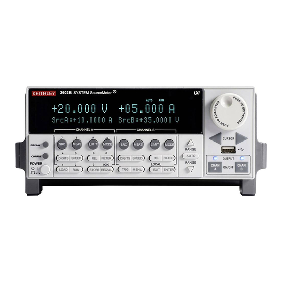
Page 15: Figure 1-1 Series 2600 Front Panels
Series 2600 System SourceMeters User’s Manual Front Panel Operation Figure 1-1 Series 2600 front panels Model 2601 and Model 2611 KEITHLEY SourceMeter POWER Model 2602 and Model 2612 KEITHLEY SourceMeter POWER NOTE The Models 2601 and 2611 have one SourceMeter channel (Channel A) and the Models 2602 and 2612 have two SourceMeter channels (Channel A and Channel B). - Page 16 Front Panel Operation Series 2600 System SourceMeters User’s Manual 1. Special keys and power switch: DISPLAY Toggles between the various source-measure displays and the user message mode. Selects Model 2602/2612 single or dual-channel display. CONFIG Used to configure a function or operation. POWER Power switch –...
- Page 17 Series 2600 System SourceMeters User’s Manual Front Panel Operation Bottom Row – Source measure setup Models 2601/2611 2602/2612: LOAD Loads factory or user-defined scripts for execution. Runs last selected factory or user-defined scripts. STORE Stores readings, source values, and timestamp values in one of two internal buffers for later recall.
-
Page 18: Figure 1-2 Series 2600 Rear Panels
Front Panel Operation Series 2600 System SourceMeters User’s Manual Rear panel overview The rear panels of the Series 2600 are is shown in Figure 1-2. Summaries of the rear panel components follow Figure 1-2. Figure 1-2 Series 2600 rear panel CHANNEL A CAT I CHANNEL A... - Page 19 Input/output connections for source, sense, and guard. 2. DIGITAL I/O Female DB-25 connector. Fourteen pins for digital input or output, one pin for Output Enable. Use a cable equipped with a male DB-25 connector (Keithley Instruments part number CA-126-1CA). 3. IEEE-488 Connector for IEEE-488 (GPIB) operation.
-
Page 20: What Are The Source-Measure Capabilities
Front Panel Operation Series 2600 System SourceMeters User’s Manual What are the source-measure capabilities? Reference Refer to the specifications in Appendix A of this manual as well as Sections 4 and 8 of the Series 2600 Reference Manual for more detailed information. -
Page 21: How Do I Power-Up The Instrument
• The node and the GPIB address are displayed briefly as follows: KEITHLEY MODEL 26xx NODE = 1 GPIB = 26 • The TSP-Link node and serial port parameters are displayed briefly:... -
Page 22: How Do I Make Measurements
1-10 Front Panel Operation Series 2600 System SourceMeters User’s Manual How do I make measurements? Reference Refer to the following information in Section 4 of the Series 2600 Reference Manual: • “Basic-source-measure procedure” • “Ohms measurements” • “Power measurements” The measurement procedure below demonstrates how to set up the Series 2600 to source 10V and measure current through a 10kΩ... - Page 23 Series 2600 System SourceMeters User’s Manual Front Panel Operation 1-11 Step 3: Set compliance limit Perform the following steps to set the current compliance limit value to 10mA: Put the Model 2602/2612 in the single-channel display mode with the DISPLAY key. Press the LIMIT key, then press ENTER or the Rotary Knob.
- Page 24 1-12 Front Panel Operation Series 2600 System SourceMeters User’s Manual Use the DISPLAY key to cycle through the various display modes shown in Figure 1-5 (The User State display messages are defined with specific display commands; refer to Section 14 of the Series 2600 Reference manual.).
-
Page 25: Figure 1-4 Interlock Circuit
Series 2600 System SourceMeters User’s Manual Front Panel Operation 1-13 Figure 1-4 Interlock circuit Read by firmware +220V supply INTERLOCK pin (on DIGITAL I/O connector) -220V supply Coil resistance 145W +/- 10% 10kW To output stage Chassis ground Rear panel Return to In this section: 2600S-900-01 Rev. -
Page 26: Figure 1-5 Display Modes
1-14 Front Panel Operation Series 2600 System SourceMeters User’s Manual Figure 1-5 Display modes DISPLAY DISPLAY DISPLAY DISPLAY 2600S-900-01 Rev. A / May 2006 Return to In this section:... -
Page 27: How Do I Use The Buffer
Series 2600 System SourceMeters User’s Manual Front Panel Operation 1-15 How do I use the buffer? Reference Refer to Section 7 of the Series 2600 Reference Manual for more detailed information on using the buffer. The SourceMeter has two buffers per channel that can store from 1 to more than 100,000 readings. - Page 28 1-16 Front Panel Operation Series 2600 System SourceMeters User’s Manual Step 4: Turn on the output Press the CHAN A (Models 2602/2612) OUTPUT ON/OFF key to turn on the source output. Step 5: Store readings Press the STORE key to store readings. The asterisk (*) annunciator turns on to indicate data storage operation is enabled.
-
Page 29: Figure 1-6 Buffer Display Format
Series 2600 System SourceMeters User’s Manual Front Panel Operation 1-17 Figure 1-6 Buffer display format Return to In this section: 2600S-900-01 Rev. A / May 2006... - Page 30 1-18 Front Panel Operation Series 2600 System SourceMeters User’s Manual This page left blank intentionally. 2600S-900-01 Rev. A / May 2006 Return to In this section:...
-
Page 31: Remote Operation
Section 2 Remote Operation In this Section: Topic Page How do I use the remote interface? Connect to the interface Select the interface Configure the interface How do I use Test Script Builder? Run Test Script Builder Open and close an instrument resource Save and clear console window Select command and language reference views How do I use TSB to make measurements? -
Page 32: How Do I Use The Remote Interface
(IEEE-488) and RS-232 connectors, and make connections as follows: • GPIB – Use a shielded IEEE-488 cable such as the Keithley Instruments Model 7007 to connect the Series 2600 IEEE-488 connector to the GPIB connector on the computer (Refer to Figure 2-1). -
Page 33: Gpib Interface Configuration
Series 2600 System SourceMeters User’s Manual Remote Operation Step 2: Select the interface Press MENU to open up the Main Menu. Select COMMUNICATION, then press ENTER. Select INTERFACE_SEL, then press ENTER. Choose GPIB for the IEEE-488 interface, RS-232 for the serial interface, or AUTO to have the instrument automatically select the interface. -
Page 34: How Do I Use Test Script Builder
Refer to Section 2 of the Series 2600 Reference Manual for com- plete details on using the Test Script Builder. Step 1: Run Test Script Builder Run the Test Script Builder program in the Keithley Instruments folder in the usual manner. The initial startup screen shown in Figure 2-3 will be displayed. - Page 35 Series 2600 System SourceMeters User’s Manual Remote Operation Key tabs include: Instrument Console – The Instrument Console is used to send commands to the connected SourceMeter. Retrieved data (e.g., readings) from commands and scripts appear in the console. Problems – When a script is saved, error checking is performed. If a script error is detected, an “X”...
-
Page 36: Figure 2-3 Test Script Builder Initial Startup Screen
Remote Operation Series 2600 System SourceMeters User’s Manual Figure 2-3 Test Script Builder initial startup screen 2600S-900-01 Rev. A / May 2006 Return to In this Section:... -
Page 37: Figure 2-4 Instrument Console Control Icons
Series 2600 System SourceMeters User’s Manual Remote Operation Figure 2-4 Instrument console control icons Step 2: Open and close an instrument resource Before you can send commands or run scripts to control the SourceMeter, you must first open the instrument resource as follows: Click on the Open Instrument icon (Refer to Figure 2-4). -
Page 38: Figure 2-5 Select Instrument Resource Dialog Box
Remote Operation Series 2600 System SourceMeters User’s Manual If you select the Simulate option, the Instrument Console will become active even though there will be no actual communication with the SourceMeter. You can simulate running a script or sending a command, but the SourceMeter will not respond. -
Page 39: How Do I Use Tsb To Make Measurements
Series 2600 System SourceMeters User’s Manual Remote Operation How do I use TSB to make measurements? Reference Refer to “Remote source-measure procedure” in Sections 4 and 12 of the Series 2600 Reference Manual for details on instrument com- mands. The following procedure uses the TSB Instrument Console to send commands to source voltage and measure current on Channel A using a 10kΩ... - Page 40 2-10 Remote Operation Series 2600 System SourceMeters User’s Manual The procedure assumes the DUT (10kΩ resistor) is already connected to the SourceMeter (Figure 1-3 in Section 1 of this manual), and that the instrument resource has already been opened (“Open and close an instrument resource”...
- Page 41 Series 2600 System SourceMeters User’s Manual Remote Operation 2-11 Step 4: Turn on output Send the following command to turn on the output: smua.source.output =smua.OUTPUT_ON Step 5: Make a measurement Enter the following command to take a current measurement: reading = smua.measure.i() Step 6: Print the result Print the result in the console window with the following command: print(reading)
-
Page 42: How Do I Use Other Programs
2-12 Remote Operation Series 2600 System SourceMeters User’s Manual How do I use other programs? Reference Refer to the LabVIEW and Visual Basic documentation for details on using those programs. Basic source-measure examples using LabVIEW and Visual Basic are shown below. -
Page 43: Figure 2-7 Labview Source-Measure Example Block Diagram
Series 2600 System SourceMeters User’s Manual Remote Operation 2-13 Figure 2-7 LabVIEW source-measure example block diagram Return to In this Section: 2600S-900-01 Rev. A / May 2006... -
Page 44: Using Visual Basic
The GUI (graphical user interface) shown in Figure 2-8 was created to demonstrate how to control a Keithley Instruments Series 2600 SourceMeter using Visual Basic 6.0. Source code for this example program can be downloaded from the Keithley Instruments internet site, www.keithley.com. - Page 45 Command sequence The commands that implement the pseudocode are listed below. The syntax for the “send” and “enter” commands is for a Keithley Instruments GPIB card. To use a Keithley Instruments GPIB card in Visual Basic, you must include the “ieeevb.bas”...
-
Page 46: Figure 2-9 Example Program Test Results
2-16 Remote Operation Series 2600 System SourceMeters User’s Manual Note: Addr% is the GPIB address of the instrument and is assigned the value of 26 Call send(Addr%, "localnode.prompts = 0", intStatus) Call send(Addr%, "reset()", intStatus) Call send(Addr%, "display.screen = display.SMUA", intStatus) Call send(Addr%, "display.smua.measure.func = display.MEASURE_DCAMPS", intStatus) Call send(Addr%, "smua.source.func = smua.OUTPUT_DCVOLTS", intStatus) Call send(Addr%, "smua.source.autorangev = smua.AUTORANGE_ON", intStatus) - Page 47 Series 2600 using NI VISA. The VISA resource is for an instrument at address 26 connected to GPIB interface #1. Once again, a Keithley Instruments GPIB card was used for this example. However, VISA allows the same code to be used with GPIB cards made by other manufacturers, or with altogether different interfaces such as the RS-232 or the Ethernet.
- Page 48 2-18 Remote Operation Series 2600 System SourceMeters User’s Manual This page left blank intentionally. 2600S-900-01 Rev. A / May 2006 Return to In this Section:...
-
Page 49: Test Script Processor Interaction
Section 3 Test Script Processor Interaction In this section: Topic Page What is a script? Factory scripts User scripts How do I run a script from the front panel? How do I interact with scripts using Test Script Builder? Running a factory script Modifying a factory script Running the user script 3-12... -
Page 50: What Is A Script
If stored in non-volatile memory, the script will not be lost when the instrument is turned off. Keithley Instruments will be posting approved user scripts donated by registered users on its web site. You will be able to download these user scripts into your Series 2600. -
Page 51: How Do I Interact With Scripts Using Test Script Builder
Series 2600 System SourceMeters User’s Manual Test Script Processor Interaction 3-3 2. Position the blinking cursor on the FACTORY or USER menu item and press ENTER (or the Rotary Knob). Keep in mind that the Series 2600 is shipped with no user scripts loaded. 3. -
Page 52: Running A Factory Script
Test Script Processor Interaction Series 2600 System SourceMeters User’s Manual Running a factory script Reference Refer to “Factory scripts” in Section 2 of the Series 2600 Reference Manual for details on running factory scripts. NOTE All commands to run a factory script are to be executed from the Instrument Console of the Test Script Builder. - Page 53 Series 2600 System SourceMeters User’s Manual Test Script Processor Interaction 3-5 Print timestamps – The following command will print the timestamps for the three measured current readings: printbuffer(1, rb1.n, rb1.timestamps) Example output: 5.555555e-02, 8.888888e-02, 1.111111e-01 Print source values – The following command will print the voltage source val- ues for the three measured current readings: printbuffer(1, rb1.n, rb1.sourcevalues) Output: 1.000000e+00, 1.000000e+00, 1.000000e+00...
-
Page 54: Modifying A Factory Script
Test Script Processor Interaction Series 2600 System SourceMeters User’s Manual Modifying a factory script Reference Refer to “Factory scripts” in Section 2 of the Series 2600 Reference Manual for more information on modifying a factory script. A factory script can be imported from the Series 2600 into the Test Script Builder where it can be modified. -
Page 55: Figure 3-2 Importing A Factory Script Project From The Series 2600
Series 2600 System SourceMeters User’s Manual Test Script Processor Interaction 3-7 Figure 3-2 Importing a factory script project from the Series 2600 File Import Import Select Existing Project From Instrument Next. Import Project From Instrument KIGeneral Finish. KIGeneral KIGeneral Return to In this section: 2600S-900-01 Rev. -
Page 56: Figure 3-3 Kigeneral Project Imported Into The Test Script Builder
Test Script Processor Interaction Series 2600 System SourceMeters User’s Manual Figure 3-3 KIGeneral project imported into the Test Script Builder Step 2: Modifying the test code for the SourceVMeasureI function As shown in Figure 3-3, the test code for the script functions is contained in the tab for the “main.tsp”... - Page 57 Series 2600 System SourceMeters User’s Manual Test Script Processor Interaction 3-9 Now assume you wish to change the bias input limits to ±10V. Edit the line of code to the following: bias = display.prompt("+00.000", " Seconds", "Enter BIAS Voltage.", 0, -10, 10) Saving the script –...
-
Page 58: Figure 3-4 Run Configuration Example - Main Tab
3-10 Test Script Processor Interaction Series 2600 System SourceMeters User’s Manual NOTE Figure 3-4 show how the Run box will look after the launch is configured. Figure 3-4 Run configuration example - Main tab shown Name KIGeneral KIGeneralUser Configurations 2. In the Configurations area of the Run box, select the KIGeneral script. The launch configuration tabs for that script will appear in the Run box. -
Page 59: Figure 3-5 Run Configuration Example - Script Attributes Tab
Series 2600 System SourceMeters User’s Manual Test Script Processor Interaction 3-11 4. As shown in Figure 3-4, the main.tsp file must be in the Load Order area of the Run box. If it is in the Available Project Files area, double-click main.tsp to move the file over. -
Page 60: Running The User Script
3-12 Test Script Processor Interaction Series 2600 System SourceMeters User’s Manual Running the user script Reference Refer to “User scripts” in Section 2 of the Series 2600 Reference Manual for details on running a user script. Remote programming The functions for the KIGeneralUser user script can be called after the script is run as follows: KIGeneralUser() After the above command is executed, any of the functions that make up the user... -
Page 61: Deleting A User Script And User Tests
Series 2600 System SourceMeters User’s Manual Test Script Processor Interaction 3-13 Deleting a user script and user tests Deleting a user script A user script can be deleted from non-volatile memory of the Series 2600. The following command will delete the KIGeneralUser user script: script.delete("KIGeneralUser") Deleting a user test After deleting a script, you should also delete the test from the USER TESTS... -
Page 62: How Do I Use Other Programs
3-14 Test Script Processor Interaction Series 2600 System SourceMeters User’s Manual How do I use other programs? Reference Refer to the LabVIEW and Visual Basic documentation for details on using those programs. Using LabVIEW Source step example The source step example is shown in Figure 3-6. -
Page 63: Figure 3-6 Labview Source Step Example
Series 2600 System SourceMeters User’s Manual Test Script Processor Interaction 3-15 Figure 3-6 LabVIEW source step example Return to In this section: 2600S-900-01 Rev. A / May 2006... -
Page 64: Using Visual Basic
Series 2600 as a traditional GPIB instrument while multi- ple measurements are performed. Source code for this example program can be downloaded from the Keithley Instruments internet site, www.keithley.com. Example script 1 – script that does not use functions The following script is in the file named “MeasCurrScript.tsp.”... -
Page 65: Figure 3-7 Gui After Loading The Non-Function Script (Gpib)
Series 2600 System SourceMeters User’s Manual Test Script Processor Interaction 3-17 Figure 3-7 GUI after loading the non-function script (GPIB) Return to In this section: 2600S-900-01 Rev. A / May 2006... - Page 66 3-18 Test Script Processor Interaction Series 2600 System SourceMeters User’s Manual --Disable automatic display of errors - leave Call send(Addr%, "localnode.showerrors = error messages in queue and enable 0", intStatus) Error Prompt. The "localnode" unit is being communicated with via GPIB or RS- 232.
- Page 67 Series 2600 System SourceMeters User’s Manual Test Script Processor Interaction 3-19 -- Disable prompts. Call send(Addr%, "localnode.prompts = 0", intStatus) The primary code that runs the script and retrieves the measurement results is listed below. This code is executed when you click the Run Script (GPIB) command button.
-
Page 68: Figure 3-8 Gui After Running The Non-Function Script (Gpib)
3-20 Test Script Processor Interaction Series 2600 System SourceMeters User’s Manual Figure 3-8 GUI after running the non-function script (GPIB) Example script 2 – script that uses functions The script used in this example is in the file named “MeasCurrFunctionScript.tsp.” This script is downloaded to the Series 2600 by selecting the Load “Function”... - Page 69 Series 2600 System SourceMeters User’s Manual Test Script Processor Interaction 3-21 to the function when it is called. Figure 3-9 shows the GUI (Graphical User Interface) after loading and running the script. Note that the Data text box does not contain any readings as in the previous example; it simply indicates that the “MeasCurr(ntimes)”...
-
Page 70: Figure 3-9 Gui After Loading And Running The Function Script (Gpib)
3-22 Test Script Processor Interaction Series 2600 System SourceMeters User’s Manual Figure 3-9 GUI after loading and running the function script (GPIB) 2600S-900-01 Rev. A / May 2006 Return to In this section:... - Page 71 Series 2600 System SourceMeters User’s Manual Test Script Processor Interaction 3-23 The primary code that calls the function and retrieves the measurement results is listed below. TSP prompts are enabled prior to calling the function. This code is executed when you click the Call Function (GPIB) command button. In this example, the function performs ten current measurements and sends the readings to the PC because “ntimes”...
-
Page 72: Figure 3-10 Gui After Calling The Function (Gpib)
3-24 Test Script Processor Interaction Series 2600 System SourceMeters User’s Manual Figure 3-10 GUI after calling the function (GPIB) 2600S-900-01 Rev. A / May 2006 Return to In this section:... -
Page 73: Controlling Multiple Sourcemeters (Tsp-Link)
Section 4 Controlling Multiple SourceMeters (TSP-Link) In this section: Topic Page How do I set up the TSP-Link system? Connect the TSP-Link system Assign node numbers Reset the TSP-Link Check the state of the TSP-Link system How do I use the expanded system? Accessing resources of TSP-Link nodes Using node[N] Using the alias (localnode) -
Page 74: How Do I Set Up The Tsp-Link System
Controlling Multiple SourceMeters Series 2600 System SourceMeters User’s Manual How do I set up the TSP-Link system? Up to 64 TSP-Link-enabled instruments (e.g., Series 2600 SourceMeters) can be connected together to form a TSP-Link system. Step 1: Connect the TSP-Link system Reference Refer to “Connections”... - Page 75 Series 2600 System SourceMeters User’s Manual Controlling Multiple SourceMeters 4-3 Table 4-1 Assigning a node number to an instrument from the front panel Series 2600 MAIN MENU 1) Press the MENU key to access MAIN MENU. 2) Select COMMUNICATION menu. 3) Select TSPLINK_CFG menu.
-
Page 76: How Do I Use The Expanded System
Controlling Multiple SourceMeters Series 2600 System SourceMeters User’s Manual Step 4: Check the state of the TSP-Link system Reference Refer to “Initialization” in Section 9 of the Series 2600 Reference Manual for more information on checking the state of the TSP-Link. read-only attribute is used to determine whether or not the tsplink.state TSP-Link reset routine was completed successfully. -
Page 77: Running Scripts In A Tsp-Link System
Series 2600 System SourceMeters User’s Manual Controlling Multiple SourceMeters 4-5 Running scripts in a TSP-Link system For remote programming, only a script stored in the Master can be run. Scripts in the Slaves cannot be accessed. Refer to “How do I interact with scripts using Test Script Builder?”... - Page 78 Controlling Multiple SourceMeters Series 2600 System SourceMeters User’s Manual This page left blank intentionally. 2600S-900-01 Rev. A / May 2006 Return to In this section:...
-
Page 79: Specifications
Appendix A Specifications In this Appendix: Model 2600S Specifications, page A-2 Return to 2600S-900-01 Rev. A / May 2006... - Page 80 ® 2601 System SourceMeter 2602 Multi-Channel I-V Test Solutions SPECIFICATION CONDITIONS ADDITIONAL SOURCE SPECIFICATIONS TRANSIENT RESPONSE TIME: <70µs for the output to recover to 0.1% for a 10% to 90% step This document contains specifications and supplemental information for the Models 2601 and 2602. change in load.
- Page 81 ® 2601 System SourceMeter Multi-Channel I-V Test Solutions 2602 METER SPECIFICATIONS GENERAL HOST INTERFACES: Computer control interfaces. VOLTAGE MEASUREMENT ACCURACY IEEE-488: IEEE-488.1 compliant. Supports IEEE-488.2 common commands and status model ACCURACY (1 Year) topology. DISPLAY INPUT 23°C ±5°C RS-232: Baud rates from 300 bps to 115200 bps. Programmable number of data bits, parity RANGE RESOLUTION RESISTANCE...
- Page 82 ® 2611 System SourceMeter 2612 Multi-Channel I-V Test Solutions SPECIFICATION CONDITIONS ADDITIONAL SOURCE SPECIFICATIONS TRANSIENT RESPONSE TIME: <70µs for the output to recover to 0.1% for a 10% to 90% step This document contains specifications and supplemental information for the Models 2611 and 2612. change in load.
- Page 83 300 µs SPEED FOR 60Hz (50Hz) ±(%rdg. + ohms) Typical tests were performed using remote operation, 4W sense, Keithley 2600-BAN cables and best, fixed measure- FAST 1 (1.2) ms 5% + 10 ment range. For more information on pulse scripts, see the Series 2600 Reference Manual.
- Page 84 ® System SourceMeter 2611 2612 Multi-Channel I-V Test Solutions GENERAL HOST INTERFACES: Computer control interfaces. IEEE-488: IEEE-488.1 compliant. Supports IEEE-488.2 common commands and status model topology. RS-232: Baud rates from 300 bps to 115200 bps. Programmable number of data bits, parity type, and flow control (RTS/CTS hard- ware or none).
- Page 85 ® Series 2600 System SourceMeter Multi-Channel I-V Test Solutions SPEED SPECIFICATIONS MAXIMUM SWEEP OPERATION RATES (operations per second) FOR 60Hz (50Hz): SOURCE MEASURE SOURCE MEASURE A/D CONVERTER MEASURE MEASURE SOURCE MEASURE SOURCE MEASURE PASS/FAIL PASS/FAIL SPEED TRIGGER ORIGIN TO MEMORY TO GPIB TO MEMORY TO GPIB...
- Page 86 Requires: • VISA (NI-VISA included on CD) • Microsoft .NET Framework (included on CD) • Keithley I/O Layer (included on CD) • Pentium III 800MHz or faster personal computer • Microsoft Windows 98, NT, 2000, or XP Each SourceMeter has two TSP-Link connectors to facilitate chaining instruments together.
-
Page 87: Frequently Asked Questions
Appendix B Frequently Asked Questions In this Appendix: How do I optimize performance? Setting speed Disabling auto zero to increase speed How do I use the Digital I/O port? Controlling the Digital I/O port How do I trigger other instruments? Triggering a scanner Programming triggering How do I generate a service request? -
Page 88: How Do I Optimize Performance
Frequently Asked Questions Series 2600 System SourceMeters User’s Manual NOTE Visit the Keithley Instruments website at www.keithley.com for more information on Frequently Asked Questions. How do I optimize performance? Reference Refer to “Operation considerations” in Section 4 and “Speed” in... -
Page 89: How Do I Use The Digital I/O Port
B-1). Each output can be set high (+5V) or low (0V), read high or low logic levels, and can be set up for triggering. Make connections using a cable with a Male DB-25 connector (Keithley Instruments part number CA- 126-1). - Page 90 Frequently Asked Questions Series 2600 System SourceMeters User’s Manual Table B-1 Commands for basic I/O port Command Description digio.readbit(bit) Read one digital I/O input line. digio.readport() Read digital I/O port. digio.writebit(bit, data) Write data to one digital I/O output line. digio.writeport(data) Write data to digital I/O port.
-
Page 91: How Do I Trigger Other Instruments
Series 2600 System SourceMeters User’s Manual Frequently Asked Questions How do I trigger other instruments? Reference Refer to “Triggering” in Section 4, “Remote digital I/O commands” in Section 11, and Section 12 of the Series 2600 Reference Manual for triggering and Digital I/O port command details. Triggering a scanner A typical test scenario might call for using the SourceMeter with a scanner to test a number of DUTs in sequence. -
Page 92: How Do I Generate A Service Request
Frequently Asked Questions Series 2600 System SourceMeters User’s Manual How do I generate a service request? Reference Refer to “Status byte and service request (SRQ)” and additional information in Appendix D of the Series 2600 Reference Manual for status model and service request details. Setting up a service request The exact programming steps necessary to generate a GPIB service request (SRQ) will vary somewhat depending on the event(s) intended to generate the... -
Page 93: How Do I Store Measurements In Non-Volatile Memory
Series 2600 System SourceMeters User’s Manual Frequently Asked Questions How do I store measurements in non-volatile memory? A Series 2600 SourceMeter has two non-volatile buffers for measured readings, source values, and timestamps: NV Buffer 1 ( nvbuffer1 ) and NV Buffer 2 ( nvbuffer2 ). - Page 94 Frequently Asked Questions Series 2600 System SourceMeters User’s Manual The three measure readings, timestamps, and source values will be stored in the buffer. Step 3: Read the buffer The following code will output the three sets of data (nine values) in the same message: rb1 = smua.nvbuffer1 printbuffer(1, rb1.n, rb1, rb1.timestamps, rb1.sourcevalues)
-
Page 95: How Do I Stack Channels To Output Higher Voltage
Series 2600 System SourceMeters User’s Manual Frequently Asked Questions How do I stack channels to output higher voltage? The maximum output voltage of a Model 2601 or 2602 channel is 40.4V, and the maximum output voltage of a Model 2611 or 2612 channel is 202V. Higher volt- age can be output by stacking (connecting in series) channels. -
Page 96: Figure B-3 Stacking Channels For Higher Voltage
B-10 Frequently Asked Questions Series 2600 System SourceMeters User’s Manual Figure B-3 Stacking channels for higher voltage – – WARNING – – Note NOTE Each stacked channel adds approximately 100μA of common mode current that is seen by the channels below it. Therefore, in the example above, Model 2602-1 Chan A will measure approximately 100μA x 3 = 300μA higher than Model 2602-2 Chan B. -
Page 97: How Do I Parallel Channels To Output Higher Current
Series 2600 System SourceMeters User’s Manual Frequently Asked Questions B-11 How do I parallel channels to output higher current? Reference Refer to Section 3 of the Series 2600 Reference Manual for details on SMU connections. The maximum DC output current of a Model 2601 or 2602 channel is as follows: •... -
Page 98: How Do I Make Contact Check Measurements
Figure B-5 Contact check connections 1. All Model 2611/2612s manufactured by Keithley Instruments support the contact check function. Only Model 2601/2602s with firmware revision 1.1.0 or later and SMU hardware revision E or later support the contact check function. To determine the firmware and SMU hardware revisions, inspect the data returned by the print(localnode.info()) command. -
Page 99: Contact Check Programming Example
Series 2600 System SourceMeters User’s Manual Frequently Asked Questions B-13 Contact check programming example The command sequence for a typical contact measurement is shown below. These commands set the contact check speed to fast and the threshold to 10Ω. A contact check measurement against the threshold is then made. - Page 100 B-14 Frequently Asked Questions Series 2600 System SourceMeters User’s Manual This page left blank intentionally. 2600S-900-01 Rev. A / May 2006 Return to In this Appendix:...
- Page 101 Index Display modes 1-12 DUT connections 1-10 Factory scripts Auto zero Front panel summaries Disabling GPIB interface Basic measurements Buffer Configuration 1-15 Configuring 1-15 How do I interact with scripts using Test Script Overview 1-15 Builder? Recalling readings 1-16 How do I parallel channels to output higher Storing readings 1-16 current?
- Page 102 Turning on Safety symbols and terms Saving a script Script Development pane Measurement Service request Function 1-11 Generating Making 1-11 Polling for Range 1-11 Programming example Setting functions 1-15 Setting up Measurements Source Basic 1-10 Selecting 1-10 Using Test Script Builder Setting functions 1-15 Menu Bar...
- Page 103 What is a script?
- Page 105 Service Form Model No. ______________ Serial No. __________________Date ________________ Name and Telephone No. _________________________________________________ Company ______________________________________________________________ List all control settings, describe problem and check boxes that apply to problem. _________________________ __________________________________________________________________________________________ __________________________________________________________________________________________ ❑ Intermittent ❑ Analog output follows display ❑ Particular range or function bad; specify _______________________________ ❑...
- Page 108 M E A S U R E C O N F I D E N C E Keithley Instruments, Inc. Corporate Headquarters • 28775 Aurora Road • Cleveland, Ohio 44139 • 440-248-0400 • Fax: 440-248-6168 • 1-888-KEITHLEY (534-8453) • www.keithley.com 12/04...
Need help?
Do you have a question about the SourceMeter 2611 and is the answer not in the manual?
Questions and answers