Proxim ORiNOCO AP-800 Installation And Management Manual
Hide thumbs
Also See for ORiNOCO AP-800:
- Software management manual (187 pages) ,
- Hardware installation manual (35 pages) ,
- Installation (2 pages)
Table of Contents
Advertisement
Quick Links
Download this manual
See also:
Installation
Advertisement
Table of Contents
Troubleshooting

Subscribe to Our Youtube Channel
Related Manuals for Proxim ORiNOCO AP-800


Summary of Contents for Proxim ORiNOCO AP-800
- Page 1 ORiNOCO® Access Points Installation and Management Guide Products Covered ORiNOCO® AP - 800 ORiNOCO® AP - 8000...
- Page 2 Disclaimer Proxim reserves the right to revise this publication and to make changes in the content from time-to-time without obligation on the part of Proxim to provide notification of such revision or change. Proxim may make improvements or changes in the product(s) described in this manual at any time.
-
Page 3: Table Of Contents
Contents Preface ..............9 Introduction . - Page 4 Commit ................. . 30 Reboot.
- Page 5 Licensed Features ................94 File Management .
- Page 6 List Commands ................131 Command Line Completion.
- Page 7 RADIUS Client Authentication Statistics ............194 Wireless Station Statistics.
- Page 8 Download a New Image Using ScanTool ............207 Download a New Image Using the Bootloader CLI .
-
Page 9: Preface
Preface Preface About this Manual Congratulations on your purchase of ORiNOCO® AP Product(s). This manual gives you a jump-start working knowledge on ORiNOCO® AP-800 and AP-8000 products, that helps you to build a wireless network application easily. It describes the device installation procedure, the device features, the technology used, and the recommended methods for configuring, monitoring and managing the device. - Page 10 Preface Screenshots This document is a combined management guide for both AP-800 and AP-8000 devices, explaining the method to configure, manage and monitor them by using Web Interface, CLI and SNMP. We are using the screenshots of AP-8000 as base to explain the concept.
-
Page 11: Introduction
Introduction This chapter contains information on the following: • About ORiNOCO® AP- Product(s) – About ORiNOCO® AP-800 – About ORiNOCO® AP-8000 • Salient Features of ORiNOCO® AP-800 and AP-8000 • Introduction to Wireless Networking • Managing and Monitoring Capabilities ORiNOCO® AP-800 and AP-8000 Installation and Management Guide... -
Page 12: About Orinoco® Ap- Product(S)
1.1 About ORiNOCO® AP- Product(s) Proxim’s ORiNOCO® AP - Products are designed to deliver flexible, scalable and reliable Data, Voice, and Video for small and medium Enterprise WLAN deployments. ORiNOCO® AP family is a classification of two products, AP-800 and AP-8000. -
Page 13: Managing And Monitoring Capabilities
Introduction 1.4 Managing and Monitoring Capabilities A Network Administrator can use the following interfaces to configure, manage and monitor the device. • Web (HTTP/HTTPS) Interface • Command Line Interface (CLI) (Terminal Emulator Programs) • Simple Network Management Protocol (SNMP) v1/v2c/v3 •... -
Page 14: Simple Network Management Protocol (Snmp)V1/V2C/V3
Introduction 1.4.2.2 Telnet You can access the device through CLI by using Telnet. With Telnet, you can communicate with the device through your LAN (switch, hub and so on), Internet, or with an ethernet cable connected directly to your computer’s ethernet port. 1.4.2.3 Secure Shell (SSH) You can securely access the device through CLI by using Secure Shell (SSH). -
Page 15: Proximvision Es (Pves)
These MIB files are available on Proxim's website at http://support.proxim.com. You need to compile one or more of the above MIBs into your SNMP program’s database before you can manage the device using SNMP. The MIB can be opened with any text editor, such as Microsoft Word, Notepad, or WordPad. -
Page 16: Installation And Initialization
Installation and Initialization This chapter contains information on how to install and mount the device. (For a quick reference on how to install and mount the device, refer to the Quick Installation Guides of ORiNOCO® AP-800 and ORiNOCO® AP-8000, respectively). This chapter covers the following topics: •... -
Page 17: Hardware Overview
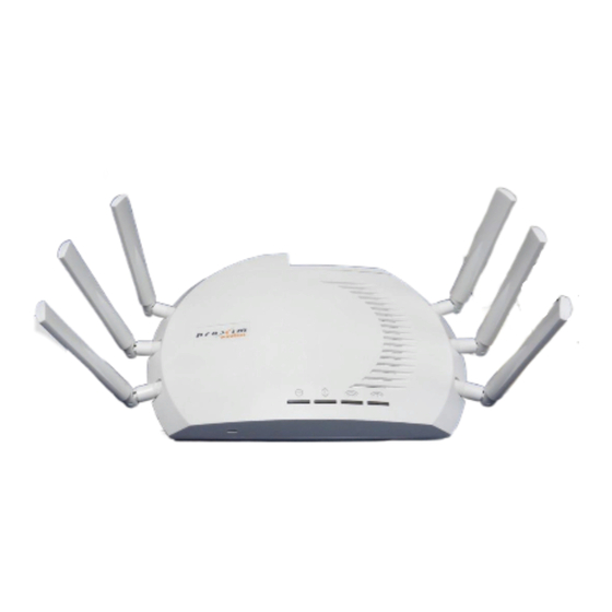
Installation and Initialization 2.1 Hardware Overview Given below is the pictorial overview of AP-800 and AP-8000. ORiNOCO® AP-800 ORiNOCO® AP-8000 Figure 2-1 Device Overview Following sections describe about the various features of the AP device. 2.1.1 LED Indicators The top panel of the AP device contains 4 LED indicators. LED Name Description Symbol... -
Page 18: Antennas
2.1.2 Antennas The AP device comes with 3x3 MIMO omni-directional antennas that are easy to install. Proxim also provides an optional accessory- Range Extender Antenna (REA), which has 3 x RP SMA plug, that can be easily connected to the device. See Install the Antennas, for details on installation of antennas on the device. -
Page 19: System Requirements
Installation and Initialization 2.2 System Requirements Following are the minimum system requirements to use the device: • Ethernet switch, cross-over or straight Ethernet cable. • IEEE 802.11- any compliant device: An 802.11a/b/g or 802.11n device. • A computer that is connected to the same IP network as the AP and has one of the following installed: –... -
Page 20: Optional Accessories
2.5 Installation Procedure This section describes the procedure to install and mount the device. For Regulatory Information and latest product updates, including firmware and the MIBs, Proxim recommends you to visit its support site at http://support.proxim.com. Perform the following steps to install and mount the device. -
Page 21: Mount The Device
The following considerations must be kept in mind when the device is mounted. • The device must be protected from the exposure, and the environmental conditions must be within those specified in the product datasheet that can be found at http://support.proxim.com. • The device uses +5 V/3.5 A power adapter. -
Page 22: Plugging In The Cables
Installation and Initialization 2.5.2.2 Ceiling Mounting 1. If the device is powered on, unplug all the power cables. 2. Place the mounting plate onto the ceiling with the embossed inverted letter “L” facing your right. 3. Fasten the mounting plate by using a pair of plastic anchors and screws provided with the Product Package. 4. -
Page 23: View Leds
Installation and Initialization 2.5.5 View LEDs When the device is powered on, it performs startup diagnostics. When startup is complete, the LEDs show the operational state of the device. The top panel of the device contains four LED indicators. Figure 2-4 LED Indicators 1. -
Page 24: Initialization
2.6.1 ScanTool Proxim’s ScanTool (Answer ID 1735) is a software utility that runs on Microsoft's Windows machine. By using ScanTool, the IP address assigned to the device can be obtained and, if required, can be changed to the IP address that is appropriate on the network. -
Page 25: Setting The Ip Address With Scantool
1. Power on, or reset the device http://support.proxim.com 2. To download Proxim’s ScanTool, log on to Proxim’s support site at and search for ScanTool with (Answer ID 1735). Upon successful download, double-click the ScanTool icon on the Windows desktop to launch the program (if the program is not already running). -
Page 26: Modifying The Ip Address
Installation and Initialization 2.6.3 Modifying the IP Address Select the device details from the Scan List and click Change. A Change screen appears as shown in the following figure. The system automatically generates the MAC address, System Name, TFTP Server IP Address and Image File Name of the device. -
Page 27: Logging Onto The Web Interface
Installation and Initialization : The device automatically reboots after clicking OK. 2.7 Logging onto the Web Interface Once the device is connected to your network, use a web browser to configure, manage and monitor the device. Enter the device IP address (For example http://169.254.128.132) in the address bar. : You can also log on to the Web Interface using ScanTool. -
Page 28: Basic Configuration
Installation and Initialization Figure 2-8 Internet Explorer Settings 2.8 Basic Configuration This section contains information on the basic configuration settings to bring up the AP device. Given below are the basic configuration settings: 1. IP Address: If you have DHCP Server on your network, then set the Address Type as Dynamic. When set to Dynamic, the device gets its IP Address from the DHCP Server. - Page 29 Installation and Initialization 4. Operational Mode: Device Operational Mode Type Radio 1 Radio 2 AP-800 802.11g/n Not Applicable AP-8000 802.11a/n 802.11g/n For details on how to change the operational mode, refer to Properties. 5. Current Bandwidth: By default, the current bandwidth is set to 40 MHz. For details on how to change the current bandwidth, refer to Properties.
-
Page 30: Home Page
Installation and Initialization 2.9 Home Page Upon successful login, the Home Page screen appears. Figure 2-9 System Summary The home page contains the following information: • Device Description: The device description is displayed on the top-right corner of the home page. It displays the logged in user type and the device name along with the latest firmware version. -
Page 31: Reboot
Installation and Initialization Figure 2-10 Commit Click OK, if you wish to commit the changed parameters. On successful Commit operation, the following screen appears: Figure 2-11 Commit Status If the configured parameters requires reboot, on committing the following screen appears. Figure 2-12 Commit Status with Reboot Message 2.9.2 Reboot Reboot operation is required for any change in the key parameters to take effect. - Page 32 Installation and Initialization Click OK, if you want to reboot the device. • Every parameter requiring REBOOT on its configuration, is marked with a red asterisk. • It is recommended that the device must be rebooted immediately after modifying a rebootable parameter. •...
-
Page 33: Factory Default Configuration
Installation and Initialization 2.10 Factory Default Configuration Parameter Default Values User Name admin Password public System Name System-Name Network Mode Bridge IP Address Assignment Type Dynamic Fall Back IP Address 169.254.128.132 Subnet Mask 255.255.0.0 Gateway IP Address 169.254.128.133 link integrity Status Disabled STP Status Disabled... - Page 34 Installation and Initialization Parameter Default Values Current Bandwidth 40 MHz VAP SSID Device SSID Type Radio 1 Radio 2 AP-800 My Wireless Network 1_1 Not Applicable AP-8000 My Wireless Network 1_1 My Wireless Network 2_1 Wireless Distribution System Disabled (WDS) Local MAC Authentication Disabled RADIUS MAC Authentication...
-
Page 35: Parameters Requiring Reboot
Installation and Initialization 2.11 Parameters requiring Reboot Parameter(s) Web Page(s) Address Type IP Address CONFIGURATION - > Network - > IP Configuration Subnet Mask Gateway IP Address DNS Primary IP and Secondary IP Address Radio Mode Country Code CONFIGURATION - > Wireless - > Interface 1/ Interface 2 - > Properties Operational Mode Current Bandwidth... -
Page 36: Device Configuration Using Web Interface
Device Configuration Using Web Interface This chapter contains information on how to configure the device by using Web Interface. Note that you can also configure the device by using other interfaces like CLI and SNMP. Following topics are covered in this chapter: •... -
Page 37: System
Device Configuration Using Web Interface 3.1 System The System feature enables you to configure system specific information. To configure System parameters, do the following: 1. Navigate to CONFIGURATION > System. The System screen appears. Figure 3-1 System 2. Configure the following parameters: •... -
Page 38: Ip Configuration
Device Configuration Using Web Interface 3.2.1 IP Configuration The IP Configuration feature enables you to configure the TCP/IP settings of the device on a network. To configure TCP/IP parameters of the device, do the following: 1. Navigate to CONFIGURATION > Network > IP Configuration. The Network IP Configuration screen appears. Figure 3-3 Network IP Configuration 2. -
Page 39: Link Integrity
Device Configuration Using Web Interface 3.2.2 Link Integrity Link Integrity helps to check the connectivity between the AP device and its pre-configured servers (routers, gateway devices and other devices in the vicinity). The device checks the link integrity by sending ICMP (Internet Control Message Protocol) echo probes periodically to the server(s). -
Page 40: Spanning Tree Protocol (Stp)
Device Configuration Using Web Interface • Link Status: Specifies connectivity status between a server and a device. Link Status can either be UP, DOWN or NONE. — UP: Specifies the Link Status when the AP device receives the server(s) acknowledgment. —... - Page 41 Device Configuration Using Web Interface b. Listening: When STP is enabled, the AP devices exchange Bridge Protocol Data Unit (BPDU) packets in listening state. These BPDU packets contain the Bridge Priority and MAC Address information, based on which a root bridge and Designated Bridge are selected.
- Page 42 Device Configuration Using Web Interface • To avoid a network loop between Bridge 1 and Bridge 2, the STP feature should be enabled on all the devices. Once the STP feature is enabled, Bridge 1, Bridge 2 and Bridge 3 change from Disable state to Listening state and start exchanging the BPDU packets.
-
Page 43: Ethernet
Device Configuration Using Web Interface • Max Age: Specifies the maximum time period for an AP device to hold the BPDU packet before discarding it. By default, the value taken is 20 seconds. To configure, enter the Max Age between 6 seconds - 40 seconds. •... -
Page 44: Wireless Interface
Device Configuration Using Web Interface • Operational TxMode: Specifies the current operational mode of transmission over the ethernet interface. There are two types of transmission modes: — Half Duplex: Allows one-way transmission at a time; where only receive or transmit operation can be performed at a time. - Page 45 Device Configuration Using Web Interface Figure 3-9 Wireless Interface-1 Properties 2. Configure the following parameters: • Radio Status: Specifies the status of the radio of the AP device. By default, the radio status is enabled. To disable, select Disable from the Radio Status box. If the radio status is disabled, the interface gets shutdown. •...
- Page 46 Device Configuration Using Web Interface • Operational Mode: This parameter determines the communication mode between the AP device and the wireless client(s). By default, the Operational Mode for Interface 1 (Radio1) is set to 802.11a/n for AP-8000 and is set to 802.11g/n for AP-800.
- Page 47 Device Configuration Using Web Interface • TPC (Transmit Power Control) Back-off: By default, the device transmits maximum output power, as per the selected frequency and country (regulatory domain). However, with TPC parameter, you can adjust the output power of the device to a lower level in order to reduce interference with the neighboring devices or to use a higher gain antenna without violating the maximum radiated output power allowed for your regulatory domain.
- Page 48 Device Configuration Using Web Interface • To balance the transmit Power and receive sensitivity at both the ends (END-A and END-B), WDS Optimization Mode should be enabled for a WDS link. • If the user wants to have AP cell size functionality applied, irrespective of the VAP type, then the TPC value can be increased, using the TPCBackoff parameter.
- Page 49 Device Configuration Using Web Interface Rouge Scanning is done via two modes: a. Current Channel Scan: In this mode, the AP device scans all the wireless devices and Rouge APs in the current operating channel, performing its normal AP functionality simultaneously. AP listens to all the data packets transmitted over the current operating channel, interprets the beacons and probe responses from the neighboring devices and maintains its BSS throughput performance.
- Page 50 Device Configuration Using Web Interface Figure 3-10 Wireless Interface-1 11n Properties 2. Configure the following parameters: • 11n AMPDU (Aggregated MAC Protocol Data Unit) Status: This parameter enables the user to aggregate several MAC frames into a single large frame to achieve high throughput. By default, AMPDU status is enabled. To disable, click Disable from the drop down menu.
- Page 51 Device Configuration Using Web Interface 3.4.1.3 Virtual Access Point (VAP) VAP is a logical entity that exists within the physical WLAN access device. The VAP enables single device to be divided into multiple VAPs, where each Access Point can be configured independently, but physical properties like Channel, Operating Mode and Power will remain same for all VAP's.
- Page 52 Device Configuration Using Web Interface Figure 3-12 Wireless Interface 1 / VAP in AP Mode - Edit Properties 1. Configure the following parameters: • Status: Specifies the status of the VAP. By default, the first VAP is always enabled and other VAPs are disabled. To enable a VAP, select Enable from the drop down menu.
- Page 53 Device Configuration Using Web Interface • Fragmentation Threshold: The process of dividing a MAC Service Data Unit (MSDU) into smaller MAC level frames for transmission over the wireless network is called Fragmentation. This reduces both the probability and adverse effects of wireless packet corruption, and thereby improving the overall wireless network performance. You can fragment the Unicast receiver address, whereas Broadcast/Multicast frames cannot be fragmented, even though they exceed a fragmentation threshold.
- Page 54 Device Configuration Using Web Interface • RADIUS Accounting: This parameter is used to either enable or disable the RADIUS Accounting Status. Click the RADIUS Accounting box to either enable or disable its status. : To enable RADIUS Accounting on a VAP, the RADIUS Accounting Server Status should be enabled. •...
- Page 55 Device Configuration Using Web Interface Lets say Access Point 1 of BSS1 wants to communicate with Access Point 2 of the BSS2 in its vicinity. In such a scenario, both the Access Points 1 and 2, register each other's MAC address. Once registered, a WDS link is established between BSS 1 and BSS 2.
- Page 56 Device Configuration Using Web Interface Figure 3-14 4 (b) VAP in WDS - 11n Mode Figure 3-14 (a) VAP in WDS - Legacy Mode 5. Configure the following parameters: • Type: Specifies the type of the VAP configured. (VAP Type may be in AP, WDS-Legacy or WDS END-A/END-B) Mode) : The AP device performs the standard AP fuctionality, if the VAP type is selected to AP mode (See •...
-
Page 57: Interface 2
Device Configuration Using Web Interface 3.4.2 Interface 2 The Interface 2 (Radio2) of the device is dedicated exclusively for Wi-Fi Coverage. To configure Wireless Interface 2 properties, Interface follow the same procedure as explained in By default, the Operational Mode for Interface 2 (Radio2) is set to 802.11g/n. However, you can also configure the operational mode for Interface 2 in either 802.11a, 802.11g or 802.11g/n modes. -
Page 58: Wireless Security
Device Configuration Using Web Interface 3.5.1 Wireless Security To configure the Wireless Security parameters, do the following: 1. Navigate to CONFIGURATION > Security > Wireless Security. The Wireless Security Configuration screen appears. Figure 3-15 Wireless Security Configuration 2. The Wireless Security Configuration screen contains the following information for the user-defined security profiles: •... - Page 59 Device Configuration Using Web Interface a. None: If you select this Authentication Mode, then no security exists on the wireless network. b. WEP (Wired Equivalent Privacy): Select WEP from the Authentication mode drop down menu and the configuration screen appears: Figure 3-17 WEP Authentication Mode Configure the following parameters in WEP mode: •...
- Page 60 — For AES or TKIP encryption, key length should be 16 ASCII characters or 32 Hex digits. — For 11na/11ng modes, WEP/TKIP Encryption will work only in Legacy (11 a/b/g) data rates. • Proxim do not recommend using WEP/TKIP in 11n mode. ORiNOCO® AP-800 and AP-8000 Installation and Management Guide...
-
Page 61: Radius
Device Configuration Using Web Interface 3.5.1.2 Edit an Existing AP Security Profile To edit an existing AP security profile, click the Edit icon against the AP security profile that you wish to edit, in the Wireless Security Configuration screen. The Wireless Security Edit Row screen appears. Figure 3-20 AP - Edit Wireless Security Profile 1. - Page 62 Device Configuration Using Web Interface 3.5.2.1 Authentication Attributes • User-Name: Specifies the name of the user that needs to be authenticated. It must be sent in Access-Request packets, if available. • User-Password: Specifies the user password to be authenticated, or the user's input following an Access-Challenge. It is only used in Access-Request packets.
- Page 63 Device Configuration Using Web Interface To configure the RADIUS Server Profile, do the following: 1. Navigate to CONFIGURATION > Security > RADIUS. The RADIUS Server Profile screen appears: Figure 3-21 RADIUS Server Profile 2. Configure the following parameters: • Profile Name: Specifies the RADIUS profile name which is used to identify a set of four RADIUS servers configured one per Accounting, Authentication, Secondary Accounting and Secondary Authentication.
-
Page 64: Mac Access Control
Device Configuration Using Web Interface • IP Address: Specifies the IP address of the RADIUS server configured. To configure, enter the IP Address in the box. • Server Port: Specifies the port number, which the device and the server use to communicate. To configure, enter the Server Port number in the box. -
Page 65: Quality Of Service (Qos)
Device Configuration Using Web Interface Figure 3-23 MAC ACL Add Row 1. Configure the following parameters: • MAC Address: Specifies the MAC Address of a wireless station being added. To configure, enter the MAC address of the wireless station. • Comment: Specifies any comment to be entered in the Comment box. -
Page 66: Enhanced Distributed Channel Access (Edca)
The EDCA parameters assign priorities to traffic types where higher priority packets gain access to the wireless medium more frequently than lower priority packets. : Default recommended values for EDCA parameters have been defined; Proxim recommends you not to modify EDCA parameters unless strictly necessary. - Page 67 Device Configuration Using Web Interface 2. The QoS EDCA screen is categorized under two headings, namely, STA EDCA Table and AP EDCA Table. The STA EDCA Table allows you to configure the EDCA parameters for the station, and AP EDCA Table allows you to configure the EDCA parameters for the AP.
-
Page 68: D To Ip Dscp Mapping Table
Device Configuration Using Web Interface Tabulated below are the default EDCA parameters for the Station and AP, specific to each Access Category. Access Default EDCA Parameters for Station Default EDCA Parameters for AP Category AIFS Tx OP AIFS Tx OP (Unsigned (Unsigned Integer) -
Page 69: D To 802.1P Mapping Table
Device Configuration Using Web Interface 2. Configure the following parameters: • 802.1d to IP DSCP Index: Specifies a read-only parameter which indicates the IP DSCP index corresponding to 802.1d priority. • Lower Limit and Upper Limit: Specifies the IP DSCP range (lower and Upper limit) for each 802.1d priority. To configure, enter the Lower Limit and Upper Limit in the range of 0 to 63, respectively for each 802.1d priority. -
Page 70: Qos Policy
Device Configuration Using Web Interface 2. Configure the following parameters: • QoS Profile Name: Specifies a read-only parameter that represents the QoS profile name. : By default, the device has only one defined QoS Profile by name Default. • Policy Name: Specifies the QoS policy name. By default, the QoS Policy Name taken is Default. •... -
Page 71: Virtual Local Area Network (Vlan)
Device Configuration Using Web Interface • Entry Status: Specifies the Entry Status. By default, it is disabled. To configure, select Enable or Disable from the drop down menu. : If you want to customize a particular Policy Type, then the Entry Status for that Policy Type should be enabled. - Page 72 Device Configuration Using Web Interface 1. Navigate to CONFIGURATION > VLAN. The VLAN screen appears. Figure 3-30 VLAN 2. Configure the following parameters: • VLAN Status: Specifies the status of the VLAN on the device. By default, it is disabled. To enable VLAN, check the VLAN Status box.
- Page 73 Device Configuration Using Web Interface When a station tries to connect to an AP device, the AP device forwards the request to the RADIUS Server (a central storage of pre- configured user profiles). On receiving the request from the AP device, the RADIUS server authenticates on what the station is authorized to do.
-
Page 74: Vlan Ethernet Configuration
Device Configuration Using Web Interface • Management VLAN Priority: Specifies the IEEE 802.1p priority set for the management frames. By default, it is set to 0. To configure, set the VLAN priority within the range of 0 to 7. 3. Click OK, to save the configured parameters. •... - Page 75 Device Configuration Using Web Interface Figure 3-34 VLAN Access Mode Configure the following parameters in Access Mode: • Access VLAN Id: Specifies an Access VLAN ID. By default, it is taken as -1. A value of -1 indicates no tag is added to the frame. To configure, enter the Access VLAN ID either as -1 or a value ranging from 1 to 4094.
-
Page 76: Filters
Device Configuration Using Web Interface • Allow Untagged Frames: To configure, either select Enable or Disable from the drop down menu. If enabled, an interface in Trunk mode forwards both tagged frames whose VLAN ID matches with one of the VLAN IDs in the trunk table and untagged frames. If disabled, an interface in Trunk mode forwards only tagged frames and drops untagged frames. -
Page 77: Protocol Filters
Device Configuration Using Web Interface • STP Frame Forward Status: Specifies STP frames on the network. By accepting the STP frames, any loops that occurs within a network can be avoided. If enabled, the STP frames in the system are bridged. When disabled, the STP frames encountered on a network are terminated at bridge. - Page 78 Device Configuration Using Web Interface Figure 3-38 Protocol Filters 2. Configure the following parameters: • Filtering Control: Specifies the parameter, used to configure the interface on which filtering has to be applied. By default, it is disabled. It can be configured as: —...
- Page 79 Device Configuration Using Web Interface — Block: The protocols with entry status Disable or the protocols which do not exist in the protocol filtering table are blocked. — Passthru: The protocols with entry status Disable or the protocols which do not exist in the protocol filtering table are allowed through the interface.
-
Page 80: Static Mac Address Filters
Device Configuration Using Web Interface Figure 3-39 Protocol Filter Add Row 2. Provide details for all the parameters and click Add. : The maximum number of Protocol Filters that can be added are 64. 3.8.2 Static MAC Address Filters The Static MAC Address filter optimizes the performance of a wireless (and wired) network. With this feature configured, the device can block traffic between wired devices and wireless devices based on the MAC address. - Page 81 Device Configuration Using Web Interface 3.8.2.1 Static MAC Filter Examples Consider a network that contains a wired interface and three wireless clients. The MAC address for each unit is as follows: • Wired Interface: 00:40:F4:1C:DB:6A • Wireless Client 1: 00:02:2D:51:94:E4 •...
- Page 82 Device Configuration Using Web Interface Figure 3-40 Static MAC Address Filters 2. To add an entry, click Add. The Static MAC Address Filter Add Row screen appears. Figure 3-41 Static MAC Address Filter - Add Entries 3. Configure the following parameters: •...
-
Page 83: Advanced Filters
Device Configuration Using Web Interface 3.8.3 Advanced Filters The Advanced Filters feature enable you to block the specific IP Protocol traffic on the network. To configure Advanced Filters, do the following: 1. Navigate to CONFIGURATION > Filters > Advanced Filters. The Advanced Filters screen appears. Figure 3-42 Advanced Filters 2. - Page 84 Device Configuration Using Web Interface 3.8.3.1 Advanced Filter table Advance Filter Table contains a list of all protocols on which Advanced Filtering is applied. 1. Protocol Name: Specifies the protocol name that is to be filtered. By default, Advanced Filters are supported on the following five default protocols: —...
-
Page 85: Tcp/Udp Port Filters
Device Configuration Using Web Interface 3.8.4 TCP/UDP Port Filters Port-based filtering enables you to control wireless user access to network services by selectively blocking TCP/UDP protocols through the device. A user specifies a Protocol Name, Port Number, Port Type (TCP, UDP, or TCP/UDP), and filtering interfaces (Only Wireless, Only Ethernet or Both) in order to block access to services such as Telnet and FTP, and traffic such as NETBIOS and HTTP. - Page 86 Device Configuration Using Web Interface 3.8.4.1 TCP/UDP Port Filter Table The TCP/UDP Port Filters screen displays a list of default protocols supported by the device and the protocols created by the user. By default, the system generates seven protocols entries. Each of the Protocol contains the following information: 1.
-
Page 87: Storm Threshold Filters
Device Configuration Using Web Interface : The maximum number of TCP/UDP Port Filters that can be added are 64. 3.8.5 Storm Threshold Filters The Storm Threshold Filter restricts the excessive inbound multicast or broadcast traffic on layer two interfaces. This protects against broadcast storms resulting from spanning tree mis-configuration. -
Page 88: Packet Forwarding
Device Configuration Using Web Interface 3.8.6 Packet Forwarding Packet Forwarding is the process of relaying the data packets, through a pre configured gateway (connected to the AP device either through ethernet interface or WDS interface). On receiving the traffic (uplink) from the stations, the AP device forwards the traffic to the destined gateway, by tagging it with the gateway MAC address. -
Page 89: Dhcp
Device Configuration Using Web Interface 3.9 DHCP Dynamic Host Configuration Protocol (DHCP) is a network protocol that enables a server to assign an IP address to a device from a defined range of IP addresses configured for a given network. It allows you to distribute IP addresses from a central point to various hosts and simplifies the process of configuring the IP addresses to individual hosts. - Page 90 Device Configuration Using Web Interface 3. Click OK, if you have changed any of the DHCP server parameters. 3.9.1.1 DHCP Interface Settings The DHCP Interface Settings Table contains the following information: 1. Net Mask: Specifies the subnet mask to be sent to the client along with the assigned IP address. The netmask configured here should be greater than or equal to the netmask configured on the interface.
- Page 91 Device Configuration Using Web Interface 1. Configure the following parameters: • Pool Interface: Specifies the interface type (ethernet or wireless). The device supports only Bridge mode. • DHCP Pool Table Start IP Address: See • DHCP Pool Table End IP Address: See •...
-
Page 92: Device Management Using Web Interface
Device Management Using Web Interface This chapter contains information on how to manage the device by using Web Interface. Note that you can also manage the device by using other interfaces like CLI and SNMP. This chapter contains information on the following: •... -
Page 93: System
Device Management Using Web Interface 4.1 System The System feature enables you to view and configure information about the device, Inventory Management and its Licensed features. 4.1.1 Information The Information feature provides you with basic system information such as System Name, System Description, Contact Details and so on. -
Page 94: Inventory Management
Device Management Using Web Interface • GPS Altitude: Specifies the altitude at which the device is installed. To configure, enter an altitude value of minimum 0 and maximum 255 characters (in the format required by your Network Management System) in the GPS Altitude box. - Page 95 Device Management Using Web Interface Figure 4-3 Licensed Features The Licensed Features screen contains the following information: • Product Description: Specifies the description of the device. • Number of Radios: Specifies the number of radios that the device is licensed to operate. •...
-
Page 96: File Management
Device Management Using Web Interface 4.2 File Management By using File Management feature, you can update the firmware or configuration files on the device, and retrieve configuration files from the device through HTTP or TFTP. HTTP file transfer can be performed with or without SSL enabled. HTTP file transfer with SSL requires enabling Secure Management and Secure Socket Layer. -
Page 97: Update Configuration
Device Management Using Web Interface Figure 4-5 Update Firmware by using TFTP 2. Click TFTP. 3. Configure the following parameters: • Server IP Address: Specifies the IP Address of the TFTP server. To configure, enter the Server IP Address. • File Name: Specifies the name of the updated firmware file (including the file extension) that has to be downloaded onto the device. - Page 98 Device Management Using Web Interface Figure 4-6 Update Configuration by using HTTP 2. In the HTTP screen, click Browse to locate the configuration file. Select “v2flashcfg.cfg” for binary configuration file and PXM-TBC.xml for text based configuration file. You can also manually enter the desired file name in the File Name box.
-
Page 99: Retrieve From Device
Device Management Using Web Interface 2. Click TFTP. 3. You can update the device with two configuration files: Binary and Text Based 4. To update the device with Binary Configuration file, select Binary Config. • Server IP Address: Specifies the IP Address of the TFTP server. To configure, enter the Server IP Address. •... - Page 100 Device Management Using Web Interface Figure 4-9 Retrieve From Device by using HTTP 2. File Type: Specifies the type of file that you want to retrieve from the device. You can retrieve the following file types: • Config: Specifies the configuration files of the device. •...
- Page 101 Device Management Using Web Interface 4.2.3.2 Retrieve from Device by using TFTP To retrieve Configuration files, Event Logs and Text Based Templates from the device by using TFTP, do the following: 1. Navigate to MANAGEMENT > File Management > Retrieve from Device. The Retrieve from Device screen appears.
- Page 102 Device Management Using Web Interface Text Based Configuration (TBC) File Management Text Based Configuration (TBC) file is a simple text file that holds device template configurations. The device supports the TBC file in XML format which can be edited in any XML or text editors. You can generate the TBC file from the CLI Session and manually edit the configurations and then load the edited TBC file to the device so that the edited configurations are applied onto the device.
- Page 103 The TBC file can easily be opened and edited in any standard Text-Editors like Wordpad, MS-Word, Notepad++, Standard XML Editors. Proxim recommends XML Notepad 7 editor for editing the TBC file. Do the following to edit the TBC file. •...
-
Page 104: Services
Device Management Using Web Interface 4.3 Services The Services feature allows you to configure the management interface (HTTP/HTTPS, Telnet/SSH and SNMP) and SYSLOG Host Table parameters that prevent from unauthorized access to the device. To configure the management interface parameters, navigate to MANAGEMENT > Services. The Services screen appears. 4.3.1 HTTP/HTTPS Figure 4-13 HTTP/HTTPS Configure the following parameters in the HTTP/HTTPS screen:... -
Page 105: Telnet/Ssh
Device Management Using Web Interface 4.3.2 Telnet/SSH Figure 4-14 Telnet/SSH Configure the following parameters in the Telnet/SSH screen: 1. Password: Specifies the password to access the device by using CLI. By default, the password is set to public. To configure, enter a new password in the Password box. The password should be alphanumeric with minimum of 6 and maximum of 32 characters. -
Page 106: Snmp
Device Management Using Web Interface 4.3.3 SNMP Figure 4-15 SNMPv1-v2c Configure the following parameters in the SNMP screen: 1. SNMP: Select Enable or Disable from the drop down menu. If enabled, it allows the user to access the device through the SNMP Interface. : Any change in the SNMP access will affect the NMS access. - Page 107 Device Management Using Web Interface Figure 4-16 SNMPv3 — Security Level: Specifies the security level of the device. The supported Security Levels for the device are None, AuthNoPriv and AuthPriv. To configure, select AuthNoPriv for Extensible Authentication, or AuthPriv for both Authentication and Privacy (Encryption), from the drop down menu.
- Page 108 Device Management Using Web Interface 4.3.3.1 SNMP Trap Host Table The SNMP Trap Host Table contains the following information: • IP Address: Specifies the IP address to which SNMP traps will be delivered. • Password: Specifies the password set to access the SNMP Trap Host Table entry. : Applicable only to SNMP v1-v2c.
-
Page 109: Syslog Host Table
Device Management Using Web Interface 4.3.4 SYSLOG Host Table System log messages are generated by the device by sending requests at various instances to the system log server. The system log messages are lost on device reboot. Figure 4-18 SYSLOG Host Table In the SYSLOG Host Table screen, do the following: 1. -
Page 110: Simple Network Time Protocol (Sntp)
Device Management Using Web Interface • Host Comment: Specifies any comment on the SYSLOG Host Table entry. • Entry Status: Specifies the entry status set for each table entry. To configure, select either Enable, Disable or Delete. If Enabled, it allows the device to send SysLog messages to the specified IP address of the SYSLOG server. If you want to delete any table entry from the SYSLOG Host Table, select Delete. -
Page 111: Access Control
Device Management Using Web Interface 2. Configure the following parameters: • Enable SNTP Status: Specifies the status of the SNTP feature on the device. Select the Enable SNTP Status checkbox to synchronize the date and time of the device with the SNTP time server. •... -
Page 112: Add A New Entry To The Access Control Table
Device Management Using Web Interface 4.5.1 Add a new Entry to the Access Control Table To add new entries to the Access Control Table, click Add in the Management Access Control Table screen. The Management Access Table Add Row screen appears. Note that you can add new entries only when the Access Table status is enabled. -
Page 113: Device Monitoring Using Web Interface
Device Monitoring Using Web Interface This chapter contains information on how to monitor the device by using Web Interface. Note that you can also monitor the device by using other interfaces like CLI and SNMP. This chapter covers the following topics: •... -
Page 114: Interface Statistics
Device Monitoring Using Web Interface 5.1 Interface Statistics Interface Statistics allow you to monitor the status and performance of the Ethernet and Wireless interfaces of the device. To view interface statistics, do the following: 1. Navigate to MONITOR > Interface Statistics. The Interface Statistics screen appears. Figure 5-1 Ethernet Interface Statistics 2. - Page 115 Device Monitoring Using Web Interface • Out Errors: Specifies the number of outbound error packets that are not allowed to transmit. • Receive CRC Errors: Specifies the total number of CRC errors occurred if the data sent is corrupted. • Collision Frames: Specifies the total number of collision frames.
-
Page 116: Station Statistics
Device Monitoring Using Web Interface • TxFragment Count: Specifies the total number of transmitted and acknowledged fragments. • RxFragment Count: Specifies the total number of fragments transmitted and received successfully. • Exfoliate Count: Specifies the total number of undelivered frames. •... - Page 117 Device Monitoring Using Web Interface • IP Address is not applicable for a WDS enabled Station. By default, it is taken as 0.0.0.0 • IP Address is not applicable, if Proxy ARP is disabled. • VAP Number: Specifies the number of the VAP, enabled on either interface 1 or interface 2. Every interface supports upto eight VAPs.
-
Page 118: Rouge Scan Statistics
Device Monitoring Using Web Interface : All the above parameters are the values taken with respect to a particular Access Point client. 4. Click Refresh, to view the updated Station Statistics. 5.3 Rouge Scan Statistics Rouge Scan allows you to monitor all the wireless devices (AP/STA/WDS/ADHOC) and Rouge APs detected, within the vicinity of your device. -
Page 119: Bridge
Device Monitoring Using Web Interface • TSLF: Specifies the time period since the last frame has been received (TSLF) over the channel. It is recorded in dd : hh : mm : ss (days: hours: minutes: seconds) • RSSI: Specifies the strength of the signal received by the detected device. The signal strength detected by the radio of the device, varies between the values 0 - 128. -
Page 120: Learn Table
Device Monitoring Using Web Interface • Out Octets: Specifies the total number of octets transmitted out of the bridge. • Out Unicast Packets: Specifies the total number of packets requested by the higher level protocol and then transmitted to the non-unicast address. •... -
Page 121: Internet Control Message Protocol (Icmp) Statistics
Device Monitoring Using Web Interface Figure 5-8 IP ARP Statistics 2. The IP ARP Table contains the following information: • Index: Specifies the interface type. • Physical Address: Specifies the MAC address of a node on the network. • Net Address: Specifies the corresponding IP address of a node on the network. •... -
Page 122: Radius
Device Monitoring Using Web Interface • In Errors/Out Errors: Specifies the number of ICMP messages that are received/transmitted by the device but determined as having ICMP-specific errors such as Bad ICMP checksums, bad length and so on. • In Dest Unreachs/Out Dest Unreachs: Specifies the number of ICMP destination unreachable messages that are received/transmitted by the device. - Page 123 Device Monitoring Using Web Interface Figure 5-10 RADIUS Client Authentication Statistics 2. The RADIUS Client Authentication Statistics screen contains the following information: • Round Trip Time: Specifies the round trip time for messages exchanged between RADIUS client and authentication server since the client startup. •...
-
Page 124: Accounting Statistics
Device Monitoring Using Web Interface 5.6.2 Accounting Statistics Accounting Statistics provides information on RADIUS Accounting for both the primary and backup servers for each RADIUS server profile. 1. To view Accounting Statistics, navigate to MONITOR > RADIUS > Accounting Statistics. The RADIUS Client Accounting Statistics screen appears. -
Page 125: Logs
Device Monitoring Using Web Interface 5.7 Logs 5.7.1 Event Log The Event Log keeps track of events that occur during the operation of the device. It displays the event occurring time, event type, and the name of the error or the error message. Based on the priority, the event details are logged and can be used for any reference or troubleshooting. -
Page 126: Syslog
Device Monitoring Using Web Interface 5.7.2 SysLog System log messages are generated by the system by sending requests at various instances to the system log server. 1. To view System Logs, navigate to MONITOR > Logs > Syslog. The SysLog screen appears. Figure 5-14 System Logs 2. - Page 127 Device Monitoring Using Web Interface 1. The SNMP v3 statistics contains the following information: • Unsupported Sec Levels: Specifies the total number of packets received by the SNMP engine which were dropped because they requested a security level that was unknown to the SNMP engine or otherwise unavailable. •...
-
Page 128: Device Configuration, Management And Monitoring Using Cli
Device Configuration, Management and Monitoring using CLI This chapter illustrates on how to configure, manage and monitor a device using Command Line Interface (CLI). Following topics are covered in this chapter. • Introduction • Accessing the Device through CLI • Configuring the Device using CLI •... -
Page 129: Introduction
Device Configuration, Management and Monitoring using CLI 6.1 Introduction The Command Line Interface (CLI) is a text-based configuration utility that supports a set of keyboard commands and parameters to configure, manage and monitor the device. You can enter the command statements composed of CLI commands and their associated parameters. -
Page 130: Error Messages
Device Configuration, Management and Monitoring using CLI 6.2.2.1 Key Combination Operation Description DEL, Backspace (BS) Deletes previous character Ctrl-B Moves back along the command line Ctrl-F Moves forward along the command line Ctrl-A Moves to the beginning of the command line Ctrl-E Moves to the end of the command line Ctrl-C... -
Page 131: List Commands
Device Configuration, Management and Monitoring using CLI 6.2.5 List Commands By using this feature, you can view a list of commands or arguments when you type the Question Mark (?) at the command prompt. When you enter a particular character followed by ?, then the command prompt will display all the commands or arguments related to the character that you have typed. -
Page 132: Rules For The Table Objects
Device Configuration, Management and Monitoring using CLI 6.2.7 Rules for the Table Objects Tables hold parameters for several related items. 6.2.7.1 Creation of a Table Entry When creating a table entry, table index and entry status are required. AP-00:7D:09 (config-mgmt-syslog-hosttbl)#rowadd 0 ? Possible Completions comment Comment Configuration... -
Page 133: Accessing The Device Through Cli
4. Enter the CLI’s default username and password, (default username is admin and password is public). • Proxim recommends changing your default passwords immediately. To perform this operation, use CLI commands. • If you have not configured the device IP address previously and do not have a DHCP server on the network, the device will use the default IP address: 169.254.128.132. -
Page 134: User Mode
Device Configuration, Management and Monitoring using CLI 6.4.1 User Mode The moment you logon to the device, with Username and Password, you enter the User mode. In this mode, you can view the configuration of few parameters only. For configuring the device, you must be in the privileged mode which can be entered by executing the “enable”... -
Page 135: Global Configuration Mode
Device Configuration, Management and Monitoring using CLI 6.4.3 Global Configuration Mode In this mode, you can configure your device. Use the ‘configure’ command to enter this mode. Example: AP-00:7D:09# configure AP-00:7D:09(config)# This brings the CLI into a special mode called “Global Configuration Mode”, where full access permissions are given to the user for configuring any available configuration of the device through CLI. -
Page 136: Configuring The Device Using Cli
Device Configuration, Management and Monitoring using CLI 6.6 Configuring the Device using CLI The Command Line Interface (CLI) is divided into different command modes. Each command mode has its own set of commands that manage the network operations. The commands that you use also depend on the mode that you are in. To configure the device parameters in Global Configuration mode use ‘configure’... -
Page 137: Commit
Device Configuration, Management and Monitoring using CLI By typing question mark with the show command in the privileged mode, you can get the show command structure and you can see the possible command’s description. AP-00:7D:09# show ? Possible completions: access-ctrl Access Control,Table Configuration dhcp DHCP Configuration... -
Page 138: Device Configuration
Device Configuration, Management and Monitoring using CLI 6.6.4 Device Configuration • The interface (radio) 2 parameters discussed in this chapter, are applicable only to AP-8000. • The ‘<value (1-2)>’ of the radio mode index in CLI configuration, is only applicable to AP-8000. •... - Page 139 Device Configuration, Management and Monitoring using CLI 6.6.4.2 Network To configure the Network Parameters, enter the following CLI commands. AP-00:7D:09(config)# network AP-00:7D:09(config-net)# ? Possible completions: clear-interface-stats Clear Interface Statistics exit Exits Back to Global Configure Mode Ethernet/Wireless Ip Configuration link-integrity link integrity Configuration STP Configuration Perform the following commands to configure the IP settings.
- Page 140 Device Configuration, Management and Monitoring using CLI Ethernet IP Configuration To configure the Ethernet IP, enter the following CLI commands. AP-00:7D:09(config-net-ip)# ethernet-ip-table AP-00:7D:09(config-net-ip-etherip)# rowedit 1 ipaddress 10.0.0.1 Changes in Ethernet IP Address requires reboot. AP-00:7D:09(config-net-ip-etherip)# rowedit 1 mask 255.255.255.0 Changes in Ethernet Subnet mask requires reboot. AP-00:7D:09(config-net-ip-etherip)# rowedit 1 address-type static Changes in Ethernet IP Address Type requires reboot.
- Page 141 Device Configuration, Management and Monitoring using CLI Link Integrity To configure the link integrity feature, enter the following CLI commands. AP-00:7D:09(config-net)# link-integrity AP-00:7D:09(config-net-link-int)# ? Possible completions: exit Exits Back to Global Configure Mode link-integrity-tbl Link Integrity Table Configuration offline-polling-time Link Integrity Offline Polling Time polling-retries Link Integrity Polling Retries polling-time...
- Page 142 Device Configuration, Management and Monitoring using CLI Spanning Tree Protocol (STP) To configure STP, enter the following CLI commands. AP-00:7D:09(config-net)# stp AP-00:7D:09(config-net-stp)# ? Possible completions: bridge-priority STP Bridge Priority Configuration exit Exits Back to Global Configure Mode forward-delay STP Forward Delay Configuration hello-time STP Hello Time Configuration max-age...
- Page 143 Device Configuration, Management and Monitoring using CLI STP Port Table: To configure the STP Port table parameters, enter the following CLI commands. AP-00:7D:09(config-net-stp)# port-table AP-00:7D:09(config-net-stp-port-tbl)# rowedit 1 priority 16 AP-00:7D:09(config-net-stp-port-tbl)# rowedit 1 path-cost 5 AP-00:7D:09(config-net-stp-port-tbl)# rowedit 1 status disable AP-00:7D:09(config-net-stp-port-tbl)# exit AP-00:7D:09(config-net-stp)# exit AP-00:7D:09(config-net)# exit AP-00:7D:09(config)# exit...
- Page 144 Device Configuration, Management and Monitoring using CLI INDEX 9 Status : enable VAP Name : ath8 Port State : forwarding Port Priority : 128 Port Path Cost INDEX 10 Status : enable VAP Name : ath9 Port State : disabled Port Priority : 128 Port Path Cost...
- Page 145 Device Configuration, Management and Monitoring using CLI Clearing All Interface Statistics To configure and clear all the interface statistics, enter the following CLI commands. AP-00:7D:09(config)# network clear-interface-stats ? Possible completions: <none(1),ethernetIntf1(2),bridgeStats(4),arpTable(5),wirelessIntf1(6),wir elessIntf2(7),learnTable(10),rogueScanIntf1(11),rogueScanIntf2(12)> Clear Interface Statistics Following are the valid configurable values for clearing Interface Statistics: •...
- Page 146 Device Configuration, Management and Monitoring using CLI 6.6.4.4 Wireless Properties To configure the wireless properties, enter the following CLI table parameters in Interface 1 and Interface 2. • To view the country code in the wireless interface properties, refer Device Configuration •...
- Page 147 Device Configuration, Management and Monitoring using CLI // WIRELESS PROPERTIES CONFIGURATION // INTERFACE 1 Radio Status : enable Operational Mode : 802.11a/n Supported Operational Modes : 802.11g/n,802.11a/n Current Channel Bandwidth : 40 MHz Supported Channel Bandwidth : 20,40 Auto Channel Selection : disable Current Configured Channel : 149...
- Page 148 Device Configuration, Management and Monitoring using CLI ******************************************************** Frequency Domains Reference List ******************************************************** ---> NoCountry ---> World All ---> Austria ---> Belgium ---> Belarus ---> Bulgaria ---> Canada ---> Cyprus ---> Czech ---> Denmark ---> Estonia ---> European ---> Finland --->...
- Page 149 Device Configuration, Management and Monitoring using CLI 11n-Properties Configuration To configure the 11n properties, enter the following CLI commands for interface 1 and interface 2. AP-00:7D:09# configure AP-00:7D:09(config)# wireless AP-00:7D:09(config-wireless)# dot11n-Properties AP-00:7D:09(config-wireless-11n-Prop)# ? Possible completions: exit Exits Back to Global Configure Mode radio Radio Index Configuration AP-00:7D:09(config-wireless-11n-Prop)# radio ?
- Page 150 Device Configuration, Management and Monitoring using CLI VAP Configuration To configure VAP in AP mode, enter the following CLI commands for interface 1 and interface 2. : Interface 2 is applicable only to AP-8000. AP-00:7D:09>enable AP-00:7D:09# configure AP-00:7D:09(config)# wireless AP-00:7D:09(config-wireless)# vap AP-00:7D:09(config-wireless-vap)# index 1 ? Possible completions: <[Enter]>...
- Page 151 Device Configuration, Management and Monitoring using CLI : Status is not applicable to the first VAP on an interface, as it is always enabled. To configure VAP in WDS mode, enter the following CLI commands: AP-00:7D:09>enable AP-00:7D:09# configure AP-00:7D:09(config)# wireless AP-00:7D:09(config-wireless)# vap AP-00:7D:09(config-wireless-vap)# index 1 AP-00:7D:09(config-wireless-vap)# index 1 secondary-index 1 broadcast-ssid...
- Page 152 Device Configuration, Management and Monitoring using CLI 6.6.4.5 Security To configure security parameters, enter the following CLI commands. AP-00:7D:09>enable AP-00:7D:09# configure AP-00:7D:09(config)# security AP-00:7D:09(config-sec)# ? Possible completions: exit Exits Back to Global Configure Mode macacl MAC-ACL Configuration radius Radius Configuration security-profile Wireless Security Configuration Wireless Security...
- Page 153 Device Configuration, Management and Monitoring using CLI PSK Security To configure the PSK authentication mode, enter the following CLI commands. AP-00:7D:09(config-sec)# security-profile AP-00:7D:09(config-sec-tbl)# rowadd 0 entry-status create AP-00:7D:09(config-sec-tbl)# rowadd 0 profile-name psk_sec AP-00:7D:09(config-sec-tbl)# rowadd 0 authentication-mode psk AP-00:7D:09(config-sec-tbl)# rowadd 0 encryption-type wpa-tkip AP-00:7D:09(config-sec-tbl)# rowadd 0 psk 0123456789963852 Pre-shared Key is configurable only in AP mode.
- Page 154 Device Configuration, Management and Monitoring using CLI • For keys, network secret and profile-name configuration characters question mark (?), double quote (“), single quote ('), back slash (\) forward slash (/), equal (=), hyphen (-) and blank spaces are not valid. •...
- Page 155 Device Configuration, Management and Monitoring using CLI Security RADIUS Supported Table Enter the following command to configure the Security RADIUS Supported table entries. AP-00:7D:09(config-sec)# radius AP-00:7D:09(config-sec-rad)#supported-table AP-00:7D:09(config-sec-rad-supported)# rowedit 1 entry-status enable AP-00:7D:09(config-sec-rad-supported)# rowedit 1 max-retransmissions 3 AP-00:7D:09(config-sec-rad-supported)# rowedit 1 msg-response-time 3 AP-00:7D:09(config-sec-rad-supported)# rowedit 1 re-authentication 0 AP-00:7D:09(config-sec-rad-supported)# rowedit 1 profile-name defaultradius...
- Page 156 Device Configuration, Management and Monitoring using CLI MAC ACL Address Table AP-00:7D:09(config)# security AP-00:7D:09(config-sec)#macacl AP-00:7D:09(config-sec-macacl)# address-table AP-00:7D:09(config-sec-macacl-address)# rowadd 1 secondary-index 0 entry-status 4 AP-00:7D:09(config-sec-macacl-address)# rowadd 1 secondary-index 0 comment firstrow AP-00:7D:09(config-sec-macacl-address)# rowadd 1 secondary-index 0 mac-address 00:11:22:33:44:55 AP-00:7D:09(config-sec-macacl-address)# rowadd 1 secondary-index 0 entry-status 4 AP-00:7D:09(config-sec-macacl-address)#exit AP-00:7D:09(config-sec-macacl)#exit...
- Page 157 Device Configuration, Management and Monitoring using CLI 802.1p Configuration To configure 802.1p do the following AP-00:7D:09(config-qos)# dot1p-mapping-table AP-00:7D:09(config-qos-dot1dmap)# ? Possible completions: exit Exits Back to Global Configure Mode rowedit Enter row number to edit/delete AP-00:7D:09(config-qos-dot1dmap)# rowedit 1 ? Possible completions: <[Enter]>...
- Page 158 Device Configuration, Management and Monitoring using CLI EDCA Table Configuration To configure the client (STA) and AP Enhanced Distributed Channel Access (EDCA) parameters do the following: AP-00:7D:09(config-qos)# edca-table AP-00:7D:09(config-qos-edca)# rowedit 1 secondary-index 1 ? Possible completions: <[Enter]> Execute this command ap-acm AP ACM Configuration ap-aifsn...
- Page 159 Device Configuration, Management and Monitoring using CLI INDEX 1.4 Profile Name : Default Sta Cwmin Sta Cwmax Sta Aifsn Sta Txop : 1.5040 Sta Acm : disable Ap Cwmin Ap Cwmax Ap Aifsn Ap Txop : 1.5040 Ap Acm : disable IP DSCP Configuration To configure IP DSCP do the following: AP-00:7D:09>enable...
- Page 160 Device Configuration, Management and Monitoring using CLI INDEX 1 Ipdscp Dscp Lower Limit : 48 Dscp Upper Limit : 55 INDEX 1 Ipdscp Dscp Lower Limit : 56 Dscp Upper Limit : 63 Policy Table Configuration To configure Policy table parameters do the following: AP-00:7D:09(config-qos)# policy-table AP-00:7D:09(config-qos-policy)# ? Possible completions:...
- Page 161 Device Configuration, Management and Monitoring using CLI Profile Table Configuration To configure Profile table parameters do the following AP-00:7D:09(config-qos)# profile-table AP-00:7D:09(config-qos-profile)# ? AP-00:7D:09(config-qos-profile)# rowedit 1 ? Possible completions: <[Enter]> Execute this command edca-profile-name EDCA Profile Name Configuration nack-status Nack Status Configuration policy-name Policy Name Configuration AP-00:7D:09(config-qos-profile)# rowedit 1 edca-profile-name Default...
- Page 162 Device Configuration, Management and Monitoring using CLI VLAN config table VLAN can operate in different modes based on the incoming traffic. To configure the VLAN Ethernet parameters, enter the following CLI commands. Access Mode AP-00:7D:09(config-vlan)# config-table AP-00:7D:09(config-vlan-configtbl)# rowedit 1 vlan-mode access AP-00:7D:09(config-vlan-configtbl)# rowedit 1 access-vlan-id 23 AP-00:7D:09(config-vlan-configtbl)# rowedit 1 access-vlan-priority 3 AP-00:7D:09(config-vlan-configtbl)# exit...
- Page 163 Device Configuration, Management and Monitoring using CLI 6.6.4.9 Filters To configure the filters, enter the following CLI commands. AP-00:7D:09(config)# filtering AP-00:7D:09(config-filter)# ? Possible completions: advanced Advanced Filter Table Configuration exit Exits Back to Global Configure Mode global-filter-control Global Filter Control Configuration intra-bss Intra BSS Configuration packet-forwarding...
- Page 164 Device Configuration, Management and Monitoring using CLI Static MAC Table To configure the Static MAC filtering table parameters, enter the following CLI commands. AP-00:7D:09 # configure AP-00:7D:09 (config)#filtering AP-00:7D:09 (config-filter)# staticmac AP-00:7D:09 (config-filter-staticmac)#rowadd 0 entry-status create AP-00:7D:09 (config-filter-staticmac)#rowadd 0 wired-mac-address 00:11:22:33:44:55 AP-00:7D:09 (config-filter-staticmac)#rowadd 0 wired-mac-mask ff:ff:ff:ff:ff:ff...
- Page 165 Device Configuration, Management and Monitoring using CLI TCP UDP Table To configure the TP UDP table parameters, enter the following CLI commands. AP-00:7D:09(config-filter)# tcpudp AP-00:7D:09(config-filter-tcpudp)# ? Possible completions: exit Exits Back to Global Configure Mode port-filter-ctrl Port Filter Control Configuration tcpudp-table TCP UDP Table Configuration AP-00:7D:09 (config-filter)#tcpudp port-filter-ctrl disable...
- Page 166 Device Configuration, Management and Monitoring using CLI INDEX 7 Protocol Name : PPTP Port Number : 1723 Port Type : both Interface : allinterfaces Entry status : disable INDEX 8 Protocol Name : HTTP Port Number : 80 Port Type : tcp Interface : ethernet...
- Page 167 Device Configuration, Management and Monitoring using CLI INDEX 3 Protocol Name : Apple-Talk-ARP-1-and-2 Protocol Number : 80:f3 Filter Status : block Entry Status : disable INDEX 4 Protocol Name : Banyan-VINES Protocol Number : 0b:ad Filter Status : block Entry Status : disable INDEX 5 Protocol Name...
- Page 168 Device Configuration, Management and Monitoring using CLI INDEX 14 Protocol Name : IP-ARP Protocol Number : 08:06 Filter Status : block Entry Status : disable INDEX 15 Protocol Name : Novell(ECONFIG-E) Protocol Number : 81:37 Filter Status : block Entry Status : disable INDEX 16 Protocol Name...
- Page 169 Device Configuration, Management and Monitoring using CLI AP-00:7D:09 (config-filter)#advanced AP-00:7D:09(config-filter-advanced)# rowedit 1 direction ethernet2wireless AP-00:7D:09(config-filter-advanced)# rowedit 1 entry-status enable AP-00:7D:09(config-filter-advanced)#exit AP-00:7D:09(config-filter)#exit AP-00:7D:09(config)#exit AP-00:7D:09# show filtering advanced // ADVANCED FILTER TABLE CONFIGURATION INDEX 1 Protocol Name : Deny-IPX-RIP Direction : ethernet2wireless Entry Status : enable INDEX 2...
- Page 170 Device Configuration, Management and Monitoring using CLI Packet Forwarding and Packet Forwarding Table To configure the packet forwarding feature on the device, enter the following CLI commands. AP-00:7D:09(config-filter)# packet-forwarding AP-00:7D:09(config-filter-packet-forward)# ? Possible completions: exit Exits Back to Global Configure Mode forwarding-tbl Packet Forwarding Table status...
- Page 171 Device Configuration, Management and Monitoring using CLI DHCP Server-Status To enable or disable the DHCP Server-Status, enter the following CLI commands. AP-00:7D:09(config-dhcp)# server-status ? Possible completions: disable(1)/dhcpserver(2) Server Status Configuration AP-00:7D:09(config-dhcp)# server-status 2 AP-00:7D:09(config)# exit AP-00:7D:09# exit AP-00:7D:09# show dhcp server-status DHCP Server Status : dhcpserver DHCP Least-time...
- Page 172 Device Configuration, Management and Monitoring using CLI Server Interface Table To configure the DHCP Server Interface Table parameters, enter the following CLI commands. AP-00:7D:09(config-dhcp)# server-interface-table AP-00:7D:09(config-dhcp-serverif)# rowedit 1 ? Possible completions: <[Enter]> Execute this command default-gateway Default Gateway Configuration default-leasetime Default Lease Time Configuration entry-status Entry Status Configuration...
-
Page 173: Managing The Device Using Cli
Device Configuration, Management and Monitoring using CLI 6.7 Managing the Device using CLI To manage the device, enter the following CLI commands. AP-00:7D:09# configure AP-00:7D:09(config)# management AP-00:7D:09(config-mgmt)# ? Possible completions: access-ctrl Access Control Configuration access-tbl-status To enable or disable the Management Access Table access-table Access Table Configuration exit... -
Page 174: Http Configuration
Device Configuration, Management and Monitoring using CLI 6.7.1.2 Access Table To configure the Access Table parameters, enter the following CLI commands. AP-00:7D:09(config-mgmt)# access-table AP-00:7D:09(config-mgmt)# access-table rowadd 1 ? Possible completions: <[Enter]> Execute this command entry-status Entry status for the Management Access Table entry-status-end Entry status for the Management Access Table (used for TBC) -
Page 175: Telnet Configuration
Device Configuration, Management and Monitoring using CLI 6.7.3 Telnet Configuration To configure password, sessions, and port number for Telnet, enter the following CLI commands. Access Control : To configure the Telnet access status as enable / disable, refer AP-00:7D:09# configure AP-00:7D:09(config)# management AP-00:7D:09(config-mgmt)# telnet ? Possible completions:... -
Page 176: Snmp Configuration
Device Configuration, Management and Monitoring using CLI 6.7.5 SNMP Configuration Access Control : To configure the SNMP access status as enable / disable, refer 6.7.5.1 SNMP v1-v2c Configuration AP-00:7D:09# configure AP-00:7D:09(config)# management AP-00:7D:09(config-mgmt)# snmp AP-00:7D:09(config-mgmt-snmp)# snmp-version snmpv1-v2c Changes in SNMP Version requires reboot. AP-00:7D:09(config-mgmt-snmp)# read-password 0123456 AP-00:7D:09(config-mgmt-snmp)# read-write-password 0123456 AP-00:7D:09(config-mgmt-snmp)# exit... -
Page 177: Trap Host Table
Device Configuration, Management and Monitoring using CLI 6.7.6 Trap Host Table To configure the SNMP Trap Host Table parameters, enter the following CLI commands. AP-00:7D:09(config-mgmt)# trap-host-table AP-00:7D:09(config-mgmt)# trap-host-table rowadd 1 ? Possible completions: <[Enter]> Execute this command comment Comment Configuration entry-status Entry Status Configuration entry-status-end... -
Page 178: Syslog And Host Table
Device Configuration, Management and Monitoring using CLI 6.7.7 Syslog and Host Table Enter the following commands to configure Syslog and Host table: AP-00:7D:09(config-mgmt-syslog)# ? Possible completions: exit Exits Back to Global Configure Mode host-table Host Table Configuration priority Configure the priority for the syslog reset reset/clear the syslog status... -
Page 179: Tftp
Device Configuration, Management and Monitoring using CLI 6.7.8 TFTP You can transfer a file to or from the device using TFTP. Make sure that the TFTP server is running and configured to point to the directory containing the file. To configure TFTP, enter the following CLI commands. AP-00:7D:09 (configure-mgmt)#tftp AP-00:7D:09 (config-mgmt-tftp)#? Possible completions:... -
Page 180: System Information
Device Configuration, Management and Monitoring using CLI 6.7.10 System Information To configure the System Information entries, enter the following CLI commands. AP-00:7D:09 # configure AP-00:7D:09(config)#management AP-00:7D:09(config-mgmt)# system-information AP-00:7D:09(config-mgmt-sys-sysinfo)# ? Possible completions: email Email address of the contact person for the device exit Exits Back to Global Configure Mode factory-reset... -
Page 181: System Inventory Management
Device Configuration, Management and Monitoring using CLI 6.7.11 System Inventory Management Inventory management provides complete component information of the device. This section describes the version history of each and every component. To view inventory information, enter the following CLI command. AP-00:7D:09# show inventory // SYSTEM INVENTORY MANAGEMENT Security Id: 0000000000000000000000000000000000000000... -
Page 182: Licensed Features
Device Configuration, Management and Monitoring using CLI INDEX 7 Serial Number : -NA- Name : Config File Component Id : 2201 Component Variant: 1 Release Version Major Version Minor Version INDEX 8 Serial Number : -NA- Name : License File Component Id : 2203 Component Variant: 2... -
Page 183: Monitoring The Device Using Cli
Device Configuration, Management and Monitoring using CLI 6.8 Monitoring the Device using CLI To monitor the device, enter the following CLI commands. AP-00:7D:09# configure AP-00:7D:09(config)# monitor AP-00:7D:09(config-mon)# ? Possible completions: eventlog Event Log Configuration exit Exits Back to Global Configure Mode station-disassociate Disassociate a station using its MAC ADDRESS 6.8.1 Event Log Configuration... - Page 184 Device Configuration, Management and Monitoring using CLI Display Event Log Message To view the event log messages, enter the following CLI commands. AP-00:7D:09# show eventlog-messages ssInterfacenoCountrySet_ap InWorldMode 00d:00h:00m:57s-->WirelessInterfacenoCountrySet_ap InWorldMode 00d:00h:01m:21s-->System Initialization Successful. 00d:03h:45m:34s--> tftp : Network is unreachable or File not Found 00d:05h:25m:50s-->Configuration Commit Successful.
-
Page 185: System Log Configuration
Device Configuration, Management and Monitoring using CLI 6.8.2 System Log Configuration To view the system log configuration, enter the following CLI commands. AP-00:7D:09# show syslog // SYSLOG CONFIGURATION // Status : enable Priority : critical Reset : no // HOST TABLE CONFIGURATION // INDEX 1 Ip Address : 10.0.0.1... -
Page 186: Clear Statistics
Device Configuration, Management and Monitoring using CLI 6.8.3 Clear Statistics To clear the event log or syslog messages, use the following CLI commands: AP-00:7D:09# AP-00:7D:09# clear ? Possible completions: eventlog-messages Clear the Event log Messages syslog-messages Clear the system log Messages To Clear Eventlog Messages: AP-00:7D:09# clear eventlog-messages To Clear Syslog Messages:... -
Page 187: Icmp Statistics Information
Device Configuration, Management and Monitoring using CLI 6.8.7 ICMP Statistics Information To view and configure the ICMP statistics, enter the following CLI commands. AP-00:7D:09# show statistics icmp // ICMP Configuration // In Messages : 29 In Errors In Destinationunreachs : 29 In TimeExcds In ParmProbs In SrcQuenchs... - Page 188 Device Configuration, Management and Monitoring using CLI Wireless Interface Statistics To view the Wireless Interface Statistics, enter the following CLI commands. AP-00:7D:09# show statistics interface // INTERFACE STATISTICS // Interface Number : 6 INDEX 1 Descripton : lo Type : softwareLoopback : 16436 Speed Physical Address...
- Page 189 Device Configuration, Management and Monitoring using CLI INDEX 4 Descripton : br0 Type : ethernet-csmacd : 1500 Speed : 100000000 Physical Address : 00:20:a6:98:76:54 Admin Status : up Operational Status : up Last Change : 0d-00h:00m:17s In Octets : 3158570 In Unicast : 18848 In Non Unicast...
- Page 190 Device Configuration, Management and Monitoring using CLI INDEX 8 Descripton : ath1 Type : ethernet-csmacd : 1500 Speed : 100000000 Physical Address : 06:02:6f:55:82:55 Admin Status : down Operational Status : down Last Change : 0d-00h:00m:17s In Octets In Unicast In Non Unicast In Errors Out Octets...
- Page 191 Device Configuration, Management and Monitoring using CLI INDEX 12 Descripton : ath5 Type : ethernet-csmacd : 1500 Speed : 100000000 Physical Address : 06:21:86:51:e5:0a Admin Status : down Operational Status : down Last Change : 0d-00h:00m:41s In Octets In Unicast In Non Unicast In Errors Out Octets...
- Page 192 Device Configuration, Management and Monitoring using CLI INDEX 16 Descripton : ath9 Type : ethernet-csmacd : 1500 Speed : 100000000 Physical Address : 02:02:6f:7f:2c:64 Admin Status : down Operational Status : down Last Change : 0d-00h:00m:47s In Octets In Unicast In Non Unicast In Errors Out Octets...
-
Page 193: Ip Arp Statistics
Device Configuration, Management and Monitoring using CLI INDEX 20 Descripton : ath13 Type : ethernet-csmacd : 1500 Speed : 100000000 Physical Address : 42:02:6f:7f:2c:64 Admin Status : down Operational Status : down Last Change : 0d-00h:00m:47s In Octets In Unicast In Non Unicast In Errors Out Octets... -
Page 194: Number Of Radios Connected
Device Configuration, Management and Monitoring using CLI 6.8.10 Number of Radios Connected To view the number of radios connected to the device, enter the following CLI commands. AP-00:7D:09# show statistics no-of-radios-connected Number Of Radios Connected : AP-800 supports only one radio. 6.8.10.1 Number of Stations Connected To view the number of stations connected to the device, enter the following CLI commands. -
Page 195: Wireless Station Statistics
Device Configuration, Management and Monitoring using CLI 6.8.13 Wireless Station Statistics To view the Wireless Station Statistics, enter the following CLI commands. AP-B4:50:03# show statistics wireless-station // WIRELESS STATION STATISTICS // INDEX 1.1 Interface Number Vap Number : 1.1 MAC Address : 00:21:5c:8a:b0:57 IP Address : 10.0.0.1... -
Page 196: Rouge Scan Statistics
Device Configuration, Management and Monitoring using CLI 6.8.15 Rouge Scan Statistics To view the Rouge Scan Statistics, enter the following CLI commands. AP-00:7D:09# show Rouge-scan // Rouge Scan STATISTICS // INTERFACE 1 INDEX SSID MAC Address : 00:20:a6:b4:4d:52 Device Type : AP Channel : 149... -
Page 197: Text Based Cli Configuration
Device Configuration, Management and Monitoring using CLI 6.8.17 Text Based CLI Configuration Enter the following CLI commands, for an overview on text based CLI configuration. AP-00:00:00# show text-based-config // FULL-CONFIGURATION // management { system-information { email name@organization.com; phone-number Contact-Phone-Number; location System-Location; gps-longitude -121.8893;... -
Page 198: Managing The Device Using Snmp
Managing the device using SNMP This chapter provides information on the following: • Introduction • Pre-requisites • Viewing the MIB Objects • Configuring the MIB Objects – To Configure the Scalar Objects – To Configure the Tabular Objects – To apply the changes to the flash memory ORiNOCO®... -
Page 199: Introduction
Ensure that you have configured the IP address of the AP device in the MIB browser. : Proxim recommends to use ProximVision ES (PVES) to make configuration changes. If you want to browse the MIB, then Proxim recommends to use NuDesign. -
Page 200: Viewing The Mib Objects
7.3 Viewing the MIB Objects 1. After configuring the pre-requisite information, load the MIB file. 2. Navigate to Proxim under the private node. • To view all the objects, right-click and select Walk. This will display all the default and configured objects. -
Page 201: Troubleshooting
This chapter helps you to address the problems that might arise while using our device. If the procedures discussed in this document does not provide a solution, or the solution does not solve your problem, check our support Web site at http://support.proxim.com. Before you start troubleshooting, check the details in the product documentation. For details about RADIUS, TFTP, Terminal and Telnet Programs, and Web Browsers, refer to their appropriate documentation. -
Page 202: Gigabit Poe Injector (Not Supplied)
Troubleshooting 8.5 Gigabit PoE Injector (Not supplied) 8.5.1 The Device Does Not Work 1. Make sure that you are using a standard UTP Category 5/Category6 cable. 2. Try a different port on the same PoE Injector hub (remember to move the input port accordingly) – if it works then there is a problem in the previous RJ45 port or a bad RJ45 port connection. -
Page 203: Serial Link Does Not Work
One of the reason for the device to reboot continuously is that the radio card is not properly placed in the mini-PCI slot. When you power on the device and you do not see the “WIRELESS NETWORK1 PASSED” message in the POST message in the Serial Console, please contact Proxim’s support site at http://support.proxim.com. 8.7.2 Lost Telnet or SNMP Password... -
Page 204: Client Computer Cannot Connect
Troubleshooting 8.7.4 Client Computer Cannot Connect 1. Client computers should have the same Network Name (VAP SSID) and security settings as the device. 2. Network Names (VAP SSIDs) should be allocated and maintained by the Network Administrator. 3. For additional troubleshooting tips, see the documentation that comes with your client card. 8.7.5 Incorrect Device IP Address 1. -
Page 205: Tftp Server Does Not Work
Troubleshooting 8.7.8 TFTP Server Does Not Work With TFTP, you can transfer files to and from the device. If a TFTP server is not properly configured and running, you cannot upload and download files. The TFTP server: • Can be situated either local or remote •... -
Page 206: Vlan Operation Issues
Troubleshooting 4. If WEP or WPA-PSK/WPA2-PSK Security mechanisms are used, then ensure that pass-phrase configured in security profile and the client are the same. 5. If WPA or WPA2 Security mechanisms are used, then ensure the EAP settings are proper in the client and the RADIUS server. -
Page 207: Hard Reset To Factory Defaults
– Download a New Image Using the Bootloader CLI As the CLI requires a physical connection to the device serial port, Proxim recommends you to use the ScanTool option. 8.8.3 Download a New Image Using ScanTool To download the device image, you will need an ethernet connection to the computer on which the TFTP server resides and to a computer that is running ScanTool (this is either two separate computers connected to the same network or a single computer running both programs). -
Page 208: Download A New Image Using The Bootloader Cli
Download Procedure Follow these steps to download a software image to the device by using ScanTool: 1. Download the latest software from http://support.proxim.com. 2. Copy the latest software updates to your TFTP server. 3. Launch Proxim’s ScanTool. -
Page 209: Setting Ip Address Using Serial Port
Troubleshooting 4. Open your terminal emulator program and set the following connection properties: • Com Port: COM1, COM2 and so on, depending on your computer • Baud Rate: 115200 • Data Bits: 8 • Stop Bits: 1 • Flow Control: None •... - Page 210 Troubleshooting 8.8.5.2 Attaching the Serial Port Cable 1. Connect one end of the serial cable to the device and the other end to a serial port on your computer. 2. Power on the computer and the device. 8.8.5.3 Initializing the IP Address using CLI After connecting the cable to the serial port, you can use the CLI to communicate with the device.
-
Page 211: Application Specific Troubleshooting
Troubleshooting Changes in Ethernet IP Address Type requires reboot. T8000-00:00:00(config-net-ip-etherip)#exit T8000-00:00:00(config-net-ip)# default-gateway <IP Gateway> T8000-00:00:00(config-net-ip)#exit T8000-00:00:00(config-net)#exit For Commit and Reboot, T8000-00:00:00(config)#commit 1 T8000-00:00:00(config)#reboot 1 4. After the device reboots, verify the new IP address by reconnecting to the CLI. Alternatively, you can ping the device from a network computer to confirm that the new IP address has taken effect. -
Page 212: A Frequently Asked Questions (Faqs)
Frequently Asked Questions (FAQs) This chapter covers the Frequently Asked Questions for the following features: • Link Integrity • Rouge Scan • Wireless Distribution Systems (WDS) • RADIUS VLAN • Packet Forwarding All the FAQs discussed on interface (radio) 2 parameters in this chapter applicable only to AP-8000. ORiNOCO®... -
Page 213: Link Integrity
Frequently Asked Questions (FAQs) Link Integrity Q. What will happen to the WDS link if a wireless interface (radio) goes down due to link integrity? WDS link will remain unaffected, if a wireless interface goes down due to link integrity. Let’s say in the same wireless interface you have 6 VAP’s and 2 WDS links. -
Page 214: Wireless Distribution Systems (Wds)
Frequently Asked Questions (FAQs) Q. How does the Rouge Scan feature on AP device, detect the Wi-Fi interferences? i) For AP Devices : APs are detected based on beacons, which has IBSS field set to 0 ii) For STA Devices : STAs are detected based on data packets which has TO DS bit=1. : All probe request packets are considered as STAs. - Page 215 Frequently Asked Questions (FAQs) Q. How different is WDS-11n mode from WDS-legacy mode, apart from data rate and throughput? • In WDS-Legacy mode, management frames are not • In WDS-11n mode, management frames are exchanged exchanged during the link establishment. Data is directly during the link establishment.
- Page 216 Frequently Asked Questions (FAQs) Q. Do I need to configure only the corresponding VAP’s at both the radios, to establish a WDS link? It’s not necessary that you use, only the corresponding VAP’s to form a WDS link. For example, you can use VAP 1 at AP1 and VAP 8 at AP2, to estsblish a WDS link.
-
Page 217: Radius Vlan
Frequently Asked Questions (FAQs) Q. What is the effect on WDS, if the link integrity is enabled and the Link Status is down? If the link integrity is enabled and the Link Status is down, then AP device disables all the VAPs enabled in AP mode only but does not interrrupt the traffic on ethernet and WDS link. -
Page 218: Packet Forwarding
Frequently Asked Questions (FAQs) Q. How to make sure that the clients are assigned with a correct VLAN ID via RADIUS server? Go to Monitor -> Station Statistics -> corresponding client and click the “show” tab, which details all the parameters including the VLAN ID assigned. -
Page 219: Ascii Character Chart
ASCII Character Chart You can configure WEP Encryption Keys in either Hexadecimal or ASCII format. Each ASCII character corresponds to two hexadecimal digits. The WEP Encryption Keys include ASCII characters consisting of 0-9, A-F, a-f (case sensitive), and punctuation marks. Tabulated below are the ASCII characters along with their Hexadecimal equivalent. -
Page 220: Bootloader Cli
Bootloader CLI The Bootloader CLI provides you the ability to configure the initial setup parameters as well as download a software image to the device. This interface is only accessible through the serial interface, and used when: • The device does not contain a software image •... - Page 221 Bootloader CLI To load the firmware from the Network • Use the show command to view parameters and their value, and use the set command to set the parameters value. To get the IP parameters dynamically for loading the firmware 1.
-
Page 222: D Technical Specifications
Technical Specifications This chapter covers the following topics: • Software Specifications • Hardware Specifications • Available Channels ORiNOCO® AP-800 and AP-8000 Installation and Management Guide... -
Page 223: Software Specifications
(62 - n) = 61 * The maximum of clients supported per VAP in an open authentication mode is 127. * Proxim recommends to connect 35 to 40 simultaneous clients for reasonable client performance. ORiNOCO® AP-800 and AP-8000 Installation and Management Guide... -
Page 224: Management Functions
(Y/N) Web User Interface (HTTP/HTTPS) CLI (Terminal Emulator Programs) SNMP Agent (SNMPv1, v2c) Secure Management (SNMP v3) ProximVision ES * (Proxim’s Network Management System) * Supported by ProximVision ES v2.3 and above. Advanced Bridging Functions Feature Supported (Y/N) Protocol Filters... -
Page 225: Security Features
Technical Specifications Security Features Feature Supported (Y/N) RADIUS VLAN per SSID/ VAP MAC Access Control RADIUS MAC-based Access Control IEEE 802.11 WEP* IEEE 802.1x Authentication Wi-Fi Protected Access (WPA)/802.11i (WPA2) VLAN * For WEP Encryption type the keys length should be (Ascii 5/13/16) (Hex 10/26/32). WEP Encryption will work only in legacy(11a/b/g) data rates. -
Page 226: Wireless Interface Features
Technical Specifications Wireless Interface Features Feature Supported (Y/N) Rouge Scan Client Load Balancing Wireless Distribution Systems (WDS) QoS Features Feature Supported (Y/N) Enhanced Distributed Coordination Access (EDCA) Per STA Software Queues System Monitoring Feature Supported (Y/N) Interface Statistics Station Statistics Rouge Scan Statistics Bridge Statistics Learn Table... -
Page 227: Hardware Specifications
Technical Specifications Hardware Specifications Category Specification Radio Module Single Radio Access Point (AP-800) / Dual Radio Access Point (AP-8000) 3x3 MIMO per radio Wireless Protocol 802.11a/n 802.11a 802.11g/n 802.11g Frequency 5.15 - 6.075 GHz* 2.4 - 2.483 GHz* * Subject to Individual Country Regulations Channel bandwidth 20MHz and 40MHz for 802.11n 20MHz for 802.11a/b/g... - Page 228 Technical Specifications Receive Sensitivity 11a/g Data Receive Data Receive Modulation Receive Rate Sensitivity Rate Sensitivity Scheme Sensitivity (Mbps) (2.4-5Ghz) (Mbps) (2.4-5Ghz) (2.4-5Ghz) MCS 0 MCS 8 MCS 10 MCS 15 *MCS refers to the Modulation Coding Scheme Local Configuration RS-232 Serial port, DB9 Female Support Remote Configuration Telnet and SSH, Web GUI (http) and SSL (https), TFTP...
-
Page 229: Available Channels
Technical Specifications Available Channels Available channels vary based on radio, country, and frequency band. To verify which channels are available for your product locate the product model number on the underside of the device or on the unit box. Below tabulated are the details on the available channels of channel bandwidths 2.4 GHz and 5 GHz, for different country codes. - Page 230 Technical Specifications Argentina 1 to 13 1 to 9 5 to 13 Austria (2412 ~ 2472) (2412 ~ 2452) (2432 ~ 2472) Belgium Brazil Bulgaria China Cyprus Czech Republic Denmark Estonia Finland France Germany Greece Hong Kong Hungary Iceland Ireland Italy Korea Latvia...
- Page 231 Technical Specifications 5 GHz CHANNELS Region (SKU) Country 20 MHz 40 PLUS MHz 40 MINUS MHz NORTH AMERICA Canada 36 (5180) 36 (5180) 40 (5200) United States 40 (5200) 44 (5220) 48 (5240) 44 (5220) 52 (5260) 56 (5280) 48 (5240) 60 (5300) 64 (5320) 52 (5260)
- Page 232 Technical Specifications Brazil 36 (5180) 36 (5180) 40 (5200) 40 (5200) 44 (5220) 48 (5240) 44 (5220) 52 (5260) 56 (5280) 48 (5240) 60 (5300) 64 (5320) 52 (5260) 100 (5500) 104 (5520) 56 (5280) 108 (5540) 112 (5560) 60 (5300) 132 (5660) 136 (5680) 64 (5320)
- Page 233 Technical Specifications Egypt 36 (5180) 36 (5180) 40 (5200) Israel 40 (5200) 44 (5220) 48 (5240) 44 (5220) 52 (5260) 56 (5280) 48 (5240) 60 (5300) 64 (5320) 52 (5260) 56 (5280) 60 (5300) 64 (5320) Hong Kong 36 (5180) 36 (5180) 40 (5200) 40 (5200)
- Page 234 Technical Specifications 124 (5620) 128 (5640) 149 (5745) 153 (5765) 157 (5785) 161 (5805) Mexico 36 (5180) 36 (5180) 40 (5200) 40 (5200) 44 (5220) 48 (5240) 44 (5220) 52 (5260) 56 (5280) 48 (5240) 60 (5300) 64 (5320) 52 (5260) 149 (5745) 153 (5765) 56 (5280)
- Page 235 Technical Specifications Russia 36 (5180) 36 (5180) 40 (5200) 40 (5200) 44 (5220) 48 (5240) 44 (5220) 52 (5260) 56 (5280) 48 (5240) 60 (5300) 64 (5320) 52 (5260) 132 (5660) 136 (5680) 56 (5280) 149 (5745) 153 (5765) 60 (5300) 157 (5785) 161 (1805) 64 (5320)
- Page 236 Technical Specifications 112 (5560) 116 (5580) 132 (5660) 136 (5680) 140 (5700) 149 (5745) 153 (5765) 157 (5785) 161 (5805) 165 (5825) Taiwan 56 (5280) 60 (5300) 64 (5320) 60 (5300) 100 (5500) 104 (5520) 64 (5320) 108 (5540) 112 (5560) 100 (5500) 132 (5660) 136 (5680)
- Page 237 Technical Specifications Poland Portugal Romania Slovakia Slovenia Spain Sweden Switzerland JAPAN Japan 36 (5180) 36 (5180) 40 (5200) 40 (5200) 44 (5220) 48 (5240) 44 (5220) 52 (5260) 56 (5280) 48 (5240) 60 (5300) 64 (5320) 52 (5260) 100 (5500) 104 (5520) 56 (5280) 108 (5540)
-
Page 238: Statement Of Warranty
The express warranties set forth in this Agreement will not apply to defects in a product caused; (i) through no fault of Proxim Wireless during shipment to or from Buyer, (ii) by the use of software other than that provided with or installed in the... -
Page 239: Other Information
In the event the Customer Service Center determines that the problem can be corrected with a software update, Buyer might be instructed to download the update from Proxim Wireless’ Web site or, if that is not possible, the update will be sent to Buyer. -
Page 240: Technical Services And Support
Obtaining Technical Service and Support If you are having trouble using the Proxim product, please read this manual and the additional documentation provided with your product. If you require additional support to resolve your issue, please be ready to provide the following information before you contact Proxim’s Technical Services:... - Page 241 Extended Warranty: Extend the life of your networking investment by adding 1, 2, or 3 years to your products standard warranty. This service coverage provides unlimited repair of your Proxim hardware for the life of the service contract. The cost of an extended warranty is far less than the cost of a repair providing a sensible return on your investment.
- Page 242 Technical Services and Support To purchase ServPak support services, please contact your authorized Proxim distributor. To receive more information or for questions on any of the available ServPak support options, call Proxim Support at 408-383-7700 or send an email to servpak@proxim.com.
Need help?
Do you have a question about the ORiNOCO AP-800 and is the answer not in the manual?
Questions and answers