
Related Manuals for Proxim ORiNOCO AP-9100


Summary of Contents for Proxim ORiNOCO AP-9100
- Page 1 ® ORiNOCO 802.11n & 802.11ac Access Points Hardware Installation Guide Products Covered ® ORiNOCO AP-800 ® ORiNOCO AP-8000 ® ORiNOCO AP-8100 ® ORiNOCO AP-9100...
- Page 2 Disclaimer Proxim reserves the right to revise this publication and to make changes in the content from time-to-time without obligation on the part of Proxim to provide notification of such revision or change. Proxim may make improvements or changes in the product(s) described in this guide at any time.
-
Page 3: Table Of Contents
Preface..............5 Introduction. - Page 4 Installation Procedure ..............19 Step 1: Plugging in the Cables .
-
Page 5: Preface
Preface Preface This chapter contains information on the following: • About this Guide • Products Covered • Audience • Prerequisites • Documentation Conventions • Related Documents About this Guide ® This guide gives a jump start working knowledge on the ORiNOCO 802.11n &... - Page 6 Caution A warning that cautions the user of a possible danger. Related Documents For more information, please refer to the following additional documents that are available at Proxim’s support site http://support.proxim.com. • Quick Installation Guide (QIG) - A quick reference guide that provides essential information to install and configure the device.
-
Page 7: Introduction
2 per radio. ® ORiNOCO AP-9100 Proxim’s ORiNOCO® AP-9100 is an indoor 802.11ac + 802.11b/g/n dual radio Access Point with dual-band (5 & 2.4 GHz) and 3x3 MIMO (Multiple Input and Multiple Output). This integrated unit comes with built-in 6 omni-directional antennas, 3 per radio. -
Page 8: Multiple-Input-Multiple-Output
Introduction AP-800/ AP-8000/ AP-8100 • Industry-leading throughput in 802.11b/g/n and 802.11a/n modes in the 2.4 GHz and 5 GHz respectively. • Highest throughput with single radio rates of 300 Mbps and dual radio rates of 600 Mbps. • Tested against Wi-Fi Alliance interoperability test suite and certified as interoperable with Wi-Fi client access product. AP-9100 •... -
Page 9: Hardware Overview And Installation
Hardware Overview and Installation This chapter covers the hardware overview and installation procedures of the following products: ® • ORiNOCO AP-800 and AP-8000 Hardware Overview — System Requirements — Product Package — Installation Procedure — ® • ORiNOCO AP-8100 Front View of the Device —... -
Page 10: Orinoco
2.2.1.2 Antennas The AP device comes with 3x3 MIMO omni-directional antennas that are easy to install. Proxim also recommends you an optional accessory - Range Extender Antenna (REA) with a 3 x RP SMA plug, that can be easily connected to the device. -
Page 11: Power Socket
Bottom View of the Device If you hold the AP device in its upright position, such that the LEDs on the top panel of the device are towards your right hand side and the ‘Proxim’ logo towards your left, then: –... -
Page 12: System Requirements
Hardware Overview and Installation 2.2.2 System Requirements Following are the minimum system requirements to use the device: 1. Any 802.11 compliant wireless adapter. 2. A computer that is connected to the same IP network as the AP and has one of the following installed: —... -
Page 13: Optional Accessories
Hardware Overview and Installation 2.2.3.1 Optional Accessories Tabulated below are the recommended optional accessories, that are supplied on request from Proxim Wireless Corporation. Accessory Image 110-220V worldwide Power Adapter Range Extender Antenna (REA) Gigabit Ethernet PoE 2.2.4 Installation Procedure Perform the following steps to install and mount the device. - Page 14 Hardware Overview and Installation Conduct a site survey to determine the best location for the device. You can either mount the device to a wall or mount it to the T-bar ceiling, as follows: Wall-Mounting: To mount the device to a wall, follow the following steps: 1.
-
Page 15: Step 3: Plugging In The Cables
Hardware Overview and Installation 2.2.4.3 Step 3: Plugging in the Cables Cabling with Power Adapter (Not supplied with the product package) To plug in the cables by using a 5V DC power adapter: • Connect one end of the CAT5e/CAT6 Ethernet cable (not supplied with the product) to the device’s ethernet port and the other end to a PC. -
Page 16: Step 6: Install Cable Security Cover (Optional)
Hardware Overview and Installation Wireless Interface • The Wireless LEDs glow steady green in operational status. (Radio) 1 LED • Blinks green, if wireless traffic is being transmitted or received. Wireless Interface (Radio) 2 LED : The LEDs glow ‘orange’ when the device initializes. 2.2.4.6 Step 6: Install Cable Security Cover (Optional) When the RS-232 cable is not connected, we recommend you to install a cable security cover to prevent the power socket, LAN ports, reset and reload buttons from getting tampered. -
Page 17: Reload
Hardware Overview and Installation 2.4G (Wireless This LED indicates the status of the traffic over the wireless interface Device Operational Modes. Interface 2) LED (radio) 2. Refer 5G (Wireless This LED indicates the status of the traffic over the wireless interface Device Operational Modes. -
Page 18: Cable Route
Hardware Overview and Installation 2.3.2.5 Cable Route A slot for the CAT5e / CAT6 ethernet cable and the power cable to rest securely. 2.3.2.6 Vent-Holes Ventilation holes on the device allow heat dissipation. 2.3.3 System Requirements Following are the minimum system requirements to use the device: 1. -
Page 19: Optional Accessories
Hardware Overview and Installation What’s in the Kit Image Quick Installation Guide (QIG) 2.3.4.1 Optional Accessories Tabulated below are the recommended optional accessories, that are supplied on request from Proxim Wireless Corporation. Accessory Part Image Description Number PoE Adapter (US/CAN/JP... -
Page 20: Step 2: Mount The Device
• The device must be protected from exposure, and the environmental conditions must be within those specified in the product datasheet that can be found at http://support.proxim.com. • Ensure to use a +12V/1.25 A power adapter, to power on the device. - Page 21 Hardware Overview and Installation Figure 2-8 Wall Mounting Ceiling Mounting: 1. Place the mounting plate on the T-bar ceiling such that the embossed letter ‘L’ is at the top-center position and the vent-holes are facing your left hand side. 2. Fasten the mounting plate by using a pair of plastic anchors and screws provided with the product package. 3.
-
Page 22: Step 3: Power On The Device
Hardware Overview and Installation Ceiling Mounting: 1. Hold the device such that the rear panel of the device is facing the mounting plate, with ‘Reload’ towards your right hand side and ‘LEDs’ towards left hand side. 2. Align the two keyholes on the device with the two holders on the mounting plate. 3. -
Page 23: Orinoco ® Ap-9100
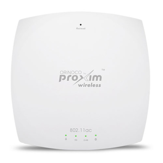
Hardware Overview and Installation ® 2.4 ORiNOCO AP-9100 2.4.1 Front View of the Device Figure 2-10 Front View of the AP-9100 The front panel of the device contains the following components: 2.4.1.1 LED Indicators Tabulated below are the four LEDs, that are available on the front panel of the device: Symbol Description Ethernet LED... -
Page 24: Rear View Of The Device
Hardware Overview and Installation 2.4.2 Rear View of the Device Figure 2-11 Rear View of the Device The rear panel of the device contains the following components: 2.4.2.1 Ethernet Port The Ethernet port of the device allows the user to connect to the LAN by using CAT5e / CAT6 ethernet cable. 2.4.2.2 Power Socket This socket connects to the 12 VDC power adapter. -
Page 25: Product Package
Hardware Overview and Installation 4. A 12V DC Power Adapter or a Power over Ethernet (PoE) Adapter. 2.4.4 Product Package Each shipment includes the items listed in the following table. Please verify that you have received all the parts in the shipment, prior to the installation. -
Page 26: Optional Accessories
Hardware Overview and Installation 2.4.4.1 Optional Accessories Tabulated below are the recommended optional accessories, that are supplied on request from Proxim Wireless Corporation. Accessory Part Image Description Number PoE Adapter (US/CAN/JP 76282 PoE module helps you Power Cord) to power ON the device via ethernet cabling. - Page 27 Hardware Overview and Installation • Note that the device is build with fire retardant FR3020 material and can be installed in the plenum. In an office building, plenum is the space between the structural ceiling and the tile ceiling that is provided to help air circulate. Many companies also use the plenum to house communication equipment and cables.
-
Page 28: Step 3: Power On The Device
Hardware Overview and Installation Ceiling Mounting: 1. Place the mounting plate on the T-bar ceiling such that the embossed letter ‘L’ is at the top-center position and the vent-holes are facing your left hand side. 2. Fasten the mounting plate by using a pair of plastic anchors and screws provided with the product package. 3. -
Page 29: Step 4: View Leds
Hardware Overview and Installation • Unplug the RJ45 connector from the Data & Power Out port on the DC injector, if using the Gigabit Ethernet PoE. 2.4.5.4 Step 4: View LEDs When the device is powered on, it performs startup diagnostics. When startup is complete, the LEDs show the operational state of the device. -
Page 30: Hardware Specifications
Hardware Specifications This chapter covers the hardware specifications of the following products: ® • ORiNOCO AP-800 and AP-8000 ® • ORiNOCO AP-8100 ® • ORiNOCO AP-9100 ® ORiNOCO 802.11n & 802.11ac Access Points - Hardware Installation Guide... - Page 31 Hardware Specifications ® 3.1 ORiNOCO AP-800 and AP-8000 Category Specification Radio Module Single Radio Access Point (AP-800) / Dual Radio Access Point (AP-8000) Device Operational Modes. 3x3 MIMO per radio. Refer Wireless Protocol 802.11a/n 802.11a 802.11b/g/n 802.11g Frequency 5.150 - 5.850 GHz* 2.4 - 2.483 GHz* * Subject to Individual Country Regulations Channel bandwidth...
- Page 32 Hardware Specifications Receive Sensitivity 11a/g Data Receive Data Receive Data Receive Rate Sensitivity Rate Sensitivity Rate Sensitivity (Mbps) (2.4-5Ghz) (Mbps) (2.4-5Ghz) (MCS*) (2.4-5Ghz) MCS 0 MCS 8 MCS 10 MCS 15 *MCS refers to Modulation Coding Scheme. Local Configuration RS-232 Serial port, DB9 Female Support Remote Configuration Telnet and SSH, Web GUI (http) and SSL (https), TFTP...
-
Page 33: Antenna Specifications
Hardware Specifications 3.1.1 Antenna Specifications • Omni Directional Antenna (Supplied with the Product) • Range Extender Antenna (REA) (Not Supplied with the product) 3.1.1.1 Omni Directional Antenna Specifications Feature Electrical Specifications Frequency Range 2400 MHz - 2500 MHz 4900 MHz – 5875 MHz Peak Gain 2.5 dBi 5 dBi... -
Page 34: Range Extender Antenna (Rea) Specifications
Hardware Specifications Feature Environmental and Mechanical Specification Radio Patterns 3.1.1.2 Range Extender Antenna (REA) Specifications Feature Electrical Specifications Frequency Range 2400 MHz - 2500 MHz 4900 MHz – 5875 MHz Peak Gain 3 dBi 6 dBi VSWR 2.0 : 1 Max 2.5 : 1 Max Polarization Linear, Vertical... - Page 35 Hardware Specifications Feature Electrical Specifications HPBW/Vertical - 50 - 27 Power Handling 2W (cw) Impedence 50 Ohms Cable ULA100-3F, White, 1.5 m Connector RP SMA Plug x 3 (Quick Connector) Lightning Protection * Exclusive of cable loss 2.5 dB @ 2.4 GHz and 5 dB @ 5.5 GHz Feature Environmental and Mechanical Specification Temperature...
- Page 36 Hardware Specifications Feature Environmental and Mechanical Specification Radio Patterns ® ORiNOCO 802.11n & 802.11ac Access Points - Hardware Installation Guide...
-
Page 37: Orinoco ® Ap-8100
Hardware Specifications ® 3.2 ORiNOCO AP-8100 Category Specification Power Power Adapter: 12V/1.25A Requirements Power over Ethernet (PoE) (optional): 48V / Any 802.3af compliant Gigabit PoE Radio Module Dual Radio Access Point, 2x2 MIMO per radio Radio1: IEEE 802.11a/n Radio2: IEEE 802.11b/g/n Device Operational Modes. - Page 38 Hardware Specifications Transmit Power AP-8100 11a/g Data Transmission Data Transmission Data Rate Transmission Rates Power* Rates Power* (MCS*) Power* (Mbps) (dBm) (Mbps) (dBm) (dBm) 1 to 11 6 to 48 MCS (0 to 5) MCS 6 MCS 7 * Combined Tx Power values * MCS refers to Modulation Coding Scheme.
-
Page 39: Antenna Specifications
Hardware Specifications 3.2.1 Antenna Specifications Feature Specification Frequency Range 2.4 GHz - 2.5 GHz 5.1 GHz – 5.825 GHz Peak Gain 3.0 dBi 4.0 dBi VSWR 2.0 : 1 2.0 : 1 Isolation (db) > 20 > 15 Impedence 50 Ohms Max.Power 1 Watts Weight... - Page 40 Hardware Specifications AP-8100 Feature Specification Radio Patterns Port-1 Radio - 1(5 GHz) Port-2 Radio Patterns Port-1 Radio - 2(2.4 GHz) Port-2 ® ORiNOCO 802.11n & 802.11ac Access Points - Hardware Installation Guide...
-
Page 41: Orinoco ® Ap-9100
Hardware Specifications ® 3.3 ORiNOCO AP-9100 Category Specification Power Power Adapter: 12V/1.25A Requirements Power over Ethernet (PoE) (optional): 48V / Any 802.3af compliant Gigabit PoE Radio Module Dual Radio Access Point, 3x3 MIMO per radio Radio1: IEEE 802.11a/n/ac (5 GHz) Radio2: IEEE 802.11b/g/n(2.4 GHz) Device Operational Modes. - Page 42 Hardware Specifications Receive Rx Sensitivity Values for Wireless Interface Radio1 & Wireless Interface Radio2: Sensitivity AP-9100 (Wireless Interface Radio1) 11ac Receiver Sensitivity Receiver Sensitivity Data Data Receiver Rate Rate Sensitivity (dBm) (dBm) (MCS*) (Mbps) (dBm) HT20 HT40 VHT80 HT20 HT40 (at 5 GHz) (at 5 GHz) (at 5 GHz)
-
Page 43: Antenna Specifications
Hardware Specifications Weight 0.400 kg (0.88 lbs) Environmental Operating Temperatures: 0 to 40ºC (32ºF to 104ºF) Storage Temperature: - 20º to 60ºC (-4ºF to 140ºF) Humidity 5% ~ 90% typical (non-condensing) MTBF >500,000 hrs Power < 12.9 watts Consumption Warranty One year parts/labor 3.3.1 Antenna Specifications Feature... - Page 44 Hardware Specifications AP-9100 Feature Specification Radio Patterns Antenna-1 Antenna-2 Radio - 1(2.45 GHz) Antenna-3 Radio Patterns Antenna-4 Antenna-5 Radio - 2(5.55 GHz) Antenna-6 ® ORiNOCO 802.11n & 802.11ac Access Points - Hardware Installation Guide...
-
Page 45: Ieee Spectral Mask Specifications
Hardware Specifications 3.3.2 IEEE Spectral Mask Specifications: Wireless Interface Radio1& Radio2 of the AP-9100 device comply with the IEEE Spectral Mask Specifications. Wireless Interface Radio1 Wireless Interface Radio2 ® ORiNOCO 802.11n & 802.11ac Access Points - Hardware Installation Guide... -
Page 46: A Glossary And Abbreviations
Glossary and Abbreviations Glossary Access point A wireless network transceiver or “base station” hub, often used to connect a local area network to one or more wireless devices. An access point (also called AP) can provide a communication link to a wired local area network also. - Page 47 Glossary and Abbreviations ScanTool Proxim’s ScanTool is a software utility that runs on Microsoft Windows machine. By using ScanTool, you can • Scan devices (Proxim devices only) available on the network • Obtain device’s IP address • Modify device’s IP Configuration parameters (IP Address, Address Type, Gateway and so on) •...
- Page 48 Glossary and Abbreviations Wi-Fi Protected Access is a security standard based on IEEE 802.11i specification, that provides a high level of wireless network security. It uses data encryption through the Temporal Key Integrity Protocol (TKIP). TKIP scrambles the keys and ensures that the keys are not tampered with. User authentication is performed through the Extensible Authentication Protocol (EAP), to ensure that only authorized network users can access the network.
- Page 49 Glossary and Abbreviations Mbps Megabits Per Second MIMO Multiple-input and multiple-output Modulation Coding Scheme OFDM Orthogonal Frequency Division Multiplexing Power Over Ethernet PIFA Planar Inverted ‘F’ Antenna Stock Keeping Unit SNMP Simple Network Management Protocol SNTP Simple Network Time Protocol Transmission Control Protocol TFTP Trivial File Transfer Protocol...
-
Page 50: B Statement Of Warranty
In the event the Customer Service Center determines that the problem can be corrected with a software update, Buyer might be instructed to download the update from Proxim Wireless’s web site or, if that’s not possible, the update will be sent to Buyer. - Page 51 Support). is fee based (detailed in If Proxim Wireless reasonably determines that a returned product is not defective or is not covered by the terms of this Warranty, Buyer shall be charged a service charge and return shipping charges. Other Information Search Knowledgebase Proxim Wireless stores all resolved problems in a solution database at the following URL: http://support.proxim.com.
-
Page 52: C Technical Services And Support
Obtaining Technical Service and Support If you are having trouble using the Proxim product, please read this guide and the additional documentation provided with your product. If you require additional support to resolve your issue, please be ready to provide the following information before you contact Proxim’s Technical Services team:... - Page 53 — Business Hours: 24x7 live response. Tier 3 support: 8 a.m. to 5 p.m. M-F PDT (UTC/GMT -7 hrs) ServPak Support To provide even greater investment protection, Proxim Wireless offers a cost-effective support program called ServPak. ServPak is a program of enhanced service support options that can be purchased as a bundle or individually, tailored to meet your specific needs.
- Page 54 Hardware is shipped on business days, Monday – Friday excluding Holidays, 8:00 AM – 3:30 PM Eastern Time. Comprehensive Advanced Replacement of Hardware In addition to ServPak Prime options, in the event of a hardware failure, Proxim will repair or replace the failed product for any reason, other than vandalism.
- Page 55 Technical Support is defined as communication via the Proxim Support website (http://my.proxim.com) and/or via telephone. This technical support will be provided for free for the entire time the product is covered by a Proxim warranty. The term of Proxim’s warranty is determined according to the agreement under which the product was sold and generally varies from 3 months to 2 years depending on the product.
-
Page 56: D Fcc Safety & Regulatory Information
FCC Safety & Regulatory Information FCC Safety Information This equipment has been tested and found to comply with the limits for a Class B digital device, pursuant to Part 15 of the FCC (Federal Communications Commission) Rules. These limits are designed to provide reasonable protection against harmful interference in a residential installation. - Page 57 FCC Safety & Regulatory Information Le présent appareil est conforme aux CNR d'Industrie Canada applicables aux appareils radio exempts de licence. L'exploitation est autorisée aux deux conditions suivantes : (1) l'appareil ne doit pas produire de brouillage, et (2) l'utilisateur de l'appareil doit accepter tout brouillage radioélectrique subi, même si le brouillage est susceptible d'en compromettre le fonctionnement.
Need help?
Do you have a question about the ORiNOCO AP-9100 and is the answer not in the manual?
Questions and answers