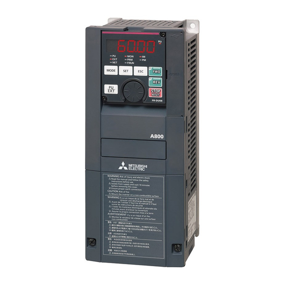
Mitsubishi Electric FR-A820-00046 (0.4K) Instruction Manual
Fr-a800 series
Hide thumbs
Also See for FR-A820-00046 (0.4K):
- Instruction manual (1218 pages) ,
- Instruction manual (914 pages) ,
- Instruction manual (1042 pages)
Table of Contents
Troubleshooting

Related Manuals for Mitsubishi Electric FR-A820-00046 (0.4K)


Summary of Contents for Mitsubishi Electric FR-A820-00046 (0.4K)
- Page 1 INVERTER FR-A800 INSTRUCTION MANUAL (DETAILED) High functionality and high performance FR-A820-00046(0.4K) to 04750(90K)(-GF) FR-A840-00023(0.4K) to 06830(280K)(-GF) FR-A842-07700(315K) to 12120(500K)(-GF) FR-A846-00023(0.4K) to 03610(132K)
-
Page 2: Table Of Contents
Safety instructions..............9 Chapter 1 INTRODUCTION . - Page 3 Parameter settings for a motor with encoder ........93 2.10 Connection of stand-alone option units .
- Page 4 4.2.3 Displaying the set frequency ............... 141 Easy setting of the inverter operation mode .
- Page 5 5.4.3 Setting procedure for Vector control (torque control) ........... . 268 5.4.4 Torque command .
- Page 6 5.9.4 Reverse rotation prevention selection..............386 5.9.5 Frequency setting via pulse train input .
- Page 7 5.14.7 Traverse function ................552 5.14.8 Anti-sway control.
- Page 8 5.21.7 Troubleshooting ................735 Chapter 6 PROTECTIVE FUNCTIONS .
- Page 9 Inverter rating ............. 790 Motor rating .
-
Page 10: Safety Instructions
• A person who possesses a certification in regard with electric appliance handling, or person took a proper engineering training. Such training may be available at your local Mitsubishi Electric office. Contact your local sales office for schedules and locations. -
Page 11: Fire Prevention
Electric shock prevention WARNING Do not remove the front cover or the wiring cover while the inverter power is ON, and do not run the inverter with the front cover or the wiring cover removed as the exposed high voltage terminals or the charging part of the circuitry can be touched. - Page 12 Injury prevention CAUTION The voltage applied to each terminal must be as specified in the Instruction Manual. Otherwise burst, damage, etc. may occur. The cables must be connected to the correct terminals. Otherwise burst, damage, etc. may occur. ...
- Page 13 CAUTION Transportation and installing Any person who is opening a package using a sharp object, such as a knife or cutter, must wear gloves to prevent injuries caused by the edge of the sharp object. The product must be transported in correct method that corresponds to the weight. Failure to do so may lead to injuries. ...
- Page 14 WARNING Usage Any person must stay away from the inverter after using the retry function as the inverter will restart suddenly after inverter output shutoff. It may happen depending on the inverter's function settings that the inverter does not stop its output even when the STOP/RESET key on the operation panel is pressed.
- Page 15 CAUTION Usage The electronic thermal O/L relay function may not be enough for protection of a motor from overheating. It is recommended to install an external thermal relay or a PTC thermistor for overheat protection. Do not use a magnetic contactor on the inverter input side for frequent starting/stopping of the inverter. Otherwise the life of the inverter decreases.
- Page 16 CHAPTER 1 INTRODUCTION Product checking and accessories .........................17 Component names ..............................19 Operation steps ..............................21 About the related manuals............................23...
-
Page 17: Chapter 1 Introduction
Parameter unit Parameter unit (FR-PU07) Operation panel and parameter unit Inverter Mitsubishi Electric inverter FR-A800 series FR-A800-GF FR-A800 series inverter with built-in CC-Link IE Field Network communication function Vector control compatible option FR-A8AP/FR-A8AL/FR-A8APR/FR-A8APS (plug-in option), FR-A8TP (control terminal option) Parameter number (Number assigned to function) -
Page 18: Product Checking And Accessories
Product checking and accessories Unpack the product and check the rating plate and the capacity plate of the inverter to ensure that the model agrees with the order and the product is intact. Inverter model ∗1 Symbol Voltage class Symbol Structure, functionality Symbol Description... - Page 19 Accessory • Fan cover fixing screws These screws are necessary for compliance with the EU Directives. (Refer to the Instruction Manual (Startup).) Capacity Screw size (mm) Quantity FR-A820-00105(1.5K) to FR-A820-00250(3.7K) M3×35 FR-A840-00083(2.2K), FR-A840-00126(3.7K) FR-A820-00340(5.5K), FR-A820-00490(7.5K) M3×35 FR-A840-00170(5.5K), FR-A840-00250(7.5K) FR-A820-00630(11K) to FR-A820-01250(22K) M4×40 FR-A840-00310(11K) to FR-A840-00620(22K) •...
-
Page 20: Component Names
Component names Component names are as follows. 1. INTRODUCTION 1.2 Component names... - Page 21 Refer to Symbol Name Description page Connects the operation panel or the parameter unit. This connector also PU connector enables the RS-485 communication. USB A connector Connects a USB memory device. Connects a personal computer and enables communication with FR USB mini B connector Configurator2.
-
Page 22: Operation Steps
Operation steps : Initial setting Step of operation Frequency command Installation/mounting Inverter output Wiring of the power frequency supply and motor Time (Hz) Start command Control mode selection Start command via the PU connector to give a start to give a start to give a start and RS-485 terminal of the inverter command? - Page 23 Symbol Overview Refer to page Install the inverter. Perform wiring for the power supply and the motor. Select the control method (V/F control, Advanced magnetic flux vector control, Vector control, or PM sensorless vector control). Give the start command via communication. Give both the start and frequency commands from the PU.
-
Page 24: About The Related Manuals
About the related manuals The manuals related to FR-A800 are as follows. Manual name Manual number FR-A800 Instruction Manual (Startup) IB-0600493 FR-A800-GF Instruction Manual (Startup) IB-0600600 FR-A802 (Separated Converter Type) Instruction Manual (Hardware) IB-0600533 FR-A802-GF (Separated Converter Type) Instruction Manual (Hardware) IB-0600601 FR-CC2 (Converter unit) Instruction Manual IB-0600542 FR-A806 (IP55/UL Type 12 specification) Instruction Manual (Hardware) IB-0600531ENG... - Page 25 MEMO 1. INTRODUCTION 1.4 About the related manuals...
-
Page 26: Chapter 2 Installation And Wiring
CHAPTER 2 INSTALLATION AND WIRING Peripheral devices ..............................27 Removal and reinstallation of the operation panel or the front covers..............33 Installation of the inverter and enclosure design ....................37 Terminal connection diagrams..........................46 Main circuit terminals ..............................54 Control circuit................................68 Communication connectors and terminals......................83 Connection to a motor with encoder (Vector control) .....................86 Parameter settings for a motor with encoder......................93 2.10... - Page 27 INSTALLATION AND WIRING This chapter explains the installation and the wiring of this product. Always read the instructions before use. For the separated converter type, refer to the "INSTALLATION AND WIRING" in the FR-A802 (Separated Converter Type) Instruction Manual (Hardware). For the IP55 compatible model, refer to the "INSTALLATION AND WIRING"...
-
Page 28: Peripheral Devices
Peripheral devices 2.1.1 Inverter and peripheral devices (b) Three-phase AC power supply (m) USB connector (a) Inverter USB host (A connector) Communication status indicator (LED)(USB host) (c) Molded case circuit breaker (MCCB) or earth leakage current USB device breaker (ELB), fuse (Mini B connector) Personal computer (FR Configurator 2) - Page 29 Symb Refer to Name Overview page The life of the inverter is influenced by the surrounding air temperature. The surrounding air temperature should be as low as possible within the permissible range. This must be noted especially when the inverter is installed in an enclosure.
-
Page 30: Peripheral Devices
NOTE • To prevent an electric shock, always earth (ground) the motor and inverter. • Do not install a power factor correction capacitor or surge suppressor or capacitor type filter on the inverter's output side. Doing so will cause the inverter to be shut off or the capacitor and surge suppressor to be damaged. If any of the above devices is connected, immediately remove it. - Page 31 Molded case circuit breaker / earth leakage circuit breaker • This is a matrix showing the rated current of the molded case circuit breaker (MCCB) or earth leakage circuit breaker (ELB) (NF or NV type) according to the selected inverter and rating. Without AC/DC power factor improving reactor With AC/DC power factor improving reactor Voltage...
- Page 32 • When the inverter capacity is larger than the motor capacity, select an MCCB and a magnetic contactor according to the inverter model, and select cables and reactors according to the motor output. • When the breaker installed at the inverter's input line is shut off, check for the wiring fault (short circuit), damage to internal parts of the inverter etc.
- Page 33 NOTE • The matrix shows the magnetic contactor selected according to the standards of Japan Electrical Manufacturers' Association (JEM standards) for AC-1 class. The electrical durability of magnetic contactor is 500,000 times. When the magnetic contactor is used for emergency stops during motor driving, the electrical durability is 25 times. If using an MC for emergency stop during motor driving, select an MC for the inverter input current according to the rated current against JEM 1038 standards for AC-3 class.
-
Page 34: Removal And Reinstallation Of The Operation Panel Or The Front Covers
Removal and reinstallation of the operation panel or the front covers Removal and reinstallation of the operation panel • Loosen the two screws on the operation panel. • Press the upper edge of the operation panel while pulling (These screws cannot be removed.) out the operation panel. - Page 35 Removal of the front cover (upper side) (FR-A820-01540(30K) or lower, FR-A840-00770(30K) or lower) Loosen Loosen Loosen (a) With the front cover (lower side) removed, loosen the mounting screws on the front cover (upper side). (These screws cannot be removed.) (FR-A820-00340(5.5K) to FR-A820-01540(30K) and FR-A840-00170(5.5K) to FR-A840-00770(30K) have two mounting screws.) (b) While holding the areas around the installation hooks on the sides of the front cover (upper side), pull out the cover using...
- Page 36 NOTE • When installing the front cover (upper side), fit the connector of the operation panel securely along the guides of the PU connector. Removal of the front cover (lower side) (FR-A820-01870(37K) or higher, FR-A840-00930(37K) or higher) (a) When the mounting screws are removed, the front cover (lower side) can be removed. (b) With the front cover (lower side) removed, wiring of the main circuit terminals can be performed.
- Page 37 Reinstallation of the front covers (FR-A820-01870(37K) or higher, FR- A840-00930(37K) or higher) Fasten Fasten Fasten Fasten Fasten Fasten (a) Insert the upper hooks of the front cover (upper side) into the sockets of the inverter. Securely install the front cover (upper side) to the inverter by fixing the hooks on the sides of the cover into place. (b) Tighten the mounting screw(s) at the lower part of the front cover (upper side).
-
Page 38: Installation Of The Inverter And Enclosure Design
Installation of the inverter and enclosure design When designing or manufacturing an inverter enclosure, determine the structure, size, and device layout of the enclosure by fully considering the conditions such as heat generation of the contained devices and the operating environment. An inverter unit uses many semiconductor devices. - Page 39 NOTE • For the amount of heat generated by the inverter unit, refer to page Humidity Operate the inverter within the ambient air humidity of usually 45 to 90% (up to 95% with circuit board coating). Too high humidity will pose problems of reduced insulation and metal corrosion. On the other hand, too low humidity may cause a spatial electrical breakdown.
- Page 40 Vibration, impact The vibration resistance of the inverter is up to 5.9 m/s (2.9 m/s or less for the FR-A840-04320(160K) or higher) at 10 to 55 Hz frequency and 1 mm amplitude for the directions of X, Y, Z axes. Applying vibration and impacts for a long time may loosen the structures and cause poor contacts of connectors, even if those vibration and impacts are within the specified values.
-
Page 41: Amount Of Heat Generated By The Inverter
2.3.2 Amount of heat generated by the inverter Installing the heatsink inside the enclosure When the heatsink is installed inside the enclosure, the amount of heat generated by the inverter unit is shown in the following tables. Amount of heat generated (W) Voltage Inverter model FR-A820-00046(0.4K) -
Page 42: Cooling System Types For Inverter Enclosure
Installing the heatsink outside the enclosure When the heatsink is installed outside the enclosure, the amount of heat generated by the inverter unit is shown in the following tables. (For the details on protruding the heatsink through a panel, refer to page 44.) Amount of heat generated (W) -
Page 43: Inverter Installation
• Cooling by ventilation (forced ventilation type, pipe ventilation type) • Cooling by heat exchanger or cooler (heat pipe, cooler, etc.) Cooling system Enclosure structure Comment This system is low in cost and generally used, but the Natural ventilation (enclosed enclosure size increases as the inverter capacity ventilated type) increases. - Page 44 Clearances (front) Clearances (side) FR-A820-03160(55K) or lower, FR-A820-03800(75K) or higher, FR-A840-01800(55K) or lower FR-A840-02160(75K) or higher 20 cm 10 cm or more or more 5 cm 5 cm 5 cm 10 cm 10 cm or more *1,*2 *1,*2 *1,*3 or more or more or more or more...
-
Page 45: Protruding The Heat Sink Through A Panel
Arrangement of the ventilation fan and inverter Heat generated in the inverter is blown up from the bottom of the unit as warm air by the cooling fan. When installing a ventilation fan for that heat, determine the place of ventilation fan installation after fully considering an air flow. (Air passes through areas of low resistance. - Page 46 Mount point change of installation frame from the rear to the front The upper and lower installation frames are attached on the inverter (one for each position). Change the mount point of the upper and lower installation frames from the rear to the front as shown in the figure. When reattaching the installation frames, make sure that the installation orientation is correct.
-
Page 47: Terminal Connection Diagrams
Terminal connection diagrams Type FM FR-A820-00770(15K) to 01250(22K), FR-A840-00470(18.5K) to 01800(55K) DC reactor Brake resistor∗8 (FR-HEL)∗1 Brake resistor Brake unit DC reactor (FR-ABR)∗7∗8 (Option) (FR-HEL)∗1 Sink logic Brake unit Jumper (Option) Earth Main circuit terminal ∗9 (Ground) Control circuit terminal Jumper Jumper Earth... - Page 48 For the FR-A820-03800(75K) or higher, the FR-A840-02160(75K) or higher, or whenever a 75 kW or higher motor is used, always connect a DC reactor (FR-HEL), which is available as an option. (To select a DC reactor, refer to page 790, and select one according to the applicable motor capacity.) When a DC reactor is connected to the FR-A820-03160(55K) or lower or the FR-A840-01800(55K) or lower, if a jumper is installed across terminals P1 and P/+, remove the jumper before installing the DC reactor.
- Page 49 Type CA FR-A820-00770(15K) to 01250(22K), FR-A840-00470(18.5K) to 01800(55K) DC reactor Brake resistor∗8 (FR-HEL)∗1 Brake resistor Brake unit DC reactor (FR-ABR)∗7∗8 (Option) (FR-HEL)∗1 Source logic Brake unit Jumper (Option) Main circuit terminal Earth ∗9 (Ground) Control circuit terminal Jumper Jumper Earth (Ground) Inrush...
- Page 50 For the FR-A820-03800(75K) or higher, the FR-A840-02160(75K) or higher, or whenever a 75 kW or higher motor is used, always connect a DC reactor (FR-HEL), which is available as an option. (To select a DC reactor, refer to page 790, and select one according to the applicable motor capacity.) When a DC reactor is connected to the FR-A820-03160(55K) or lower or the FR-A840-01800(55K) or lower, if a jumper is installed across terminals P1 and P/+, remove the jumper before installing the DC reactor.
- Page 51 Type FM (FR-A800-GF) FR-A820-00770(15K) to 01250(22K), FR-A840-00470(18.5K) to 01800(55K) DC reactor Brake resistor∗8 (FR-HEL)∗1 Brake resistor Brake unit DC reactor (FR-ABR)∗7∗8 (Option) (FR-HEL)∗1 Sink logic Brake unit Jumper (Option) Main circuit terminal Earth ∗9 (Ground) Control circuit terminal Jumper Jumper Earth (Ground)
- Page 52 When using separate power supply for the control circuit, remove the jumper between R1/L11 and S1/L21. The function of these terminals can be changed with the input terminal assignment (Pr.178 to Pr.189). (Refer to page 496.) Terminal JOG is also used as a pulse train input terminal. Use Pr.291 to choose JOG or pulse. Terminal input specifications can be changed by analog input specification switchover (Pr.73, Pr.267).
- Page 53 Type CA (FR-A800-GF) FR-A820-00770(15K) to 01250(22K), FR-A840-00470(18.5K) to 01800(55K) DC reactor Brake resistor∗8 (FR-HEL)∗1 Brake resistor Brake unit DC reactor (FR-ABR)∗7∗8 (Option) (FR-HEL)∗1 Source logic Brake unit Jumper (Option) Main circuit terminal Earth ∗9 (Ground) Control circuit terminal Jumper Jumper Earth (Ground)
- Page 54 For the FR-A820-03800(75K) or higher, the FR-A840-02160(75K) or higher, or whenever a 75 kW or higher motor is used, always connect a DC reactor (FR-HEL), which is available as an option. (To select a DC reactor, refer to page 790, and select one according to the applicable motor capacity.) When a DC reactor is connected to the FR-A820-03160(55K) or lower or the FR-A840-01800(55K) or lower, if a jumper is installed across terminals P1 and P/+, remove the jumper before installing the DC reactor.
-
Page 55: Main Circuit Terminals
Main circuit terminals 2.5.1 Details on the main circuit terminals Refer to Terminal symbol Terminal name Terminal function description page Connect these terminals to the commercial power supply. Do not connect anything to these terminals when using the high power R/L1, S/L2, T/L3 AC power input —... -
Page 56: Terminal Layout Of The Main Circuit Terminals, Wiring Of Power Supply And The Motor
2.5.2 Terminal layout of the main circuit terminals, wiring of power supply and the motor FR-A820-00046(0.4K), FR-A820-00077(0.75K) FR-A820-00105(1.5K) to FR-A820-00250(3.7K) FR-A840-00023(0.4K) to FR-A840-00126(3.7K) Jumper Jumper R/L1 S/L2 T/L3 Jumper R/L1 S/L2 T/L3 P/+ PR Jumper R1/L11 S1/L21 R1/L11 S1/L21 Charge lamp Power supply Motor Charge lamp... - Page 57 FR-A820-01870(37K), FR-A820-02330(45K) FR-A820-03160(55K) R1/L11 S1/L21 R1/L11 S1/L21 Charge lamp Charge lamp Jumper Jumper R/L1 S/L2 T/L3 R/L1 S/L2 T/L3 N/- Jumper Power supply Motor Jumper Power supply Motor FR-A820-03800(75K), FR-A820-04750(90K) FR-A840-00930(37K) to FR-A840-01800(55K) FR-A840-03250(110K) to FR-A840-04810(185K) R1/L11 S1/L21 R1/L11 S1/L21 Charge lamp Charge lamp Jumper...
-
Page 58: Applicable Cables And Wiring Length
NOTE • Make sure the power cables are connected to the R/L1, S/L2, and T/L3. (Phase need not be matched.) Never connect the power cable to the U, V, and W of the inverter. Doing so will damage the inverter. •... - Page 59 For the ND rating • 200 V class (220 V input power supply, without a power factor improving AC or DC reactor) Cable gauge Crimp terminal Applicable Terminal Tightening HIV cables, etc. (mm AWG/MCM PVC cables, etc. (mm inverter model screw torque R/L1,...
- Page 60 • 400 V class (440 V input power supply, with a power factor improving AC or DC reactor) Cable gauge Crimp terminal Applicable Terminal Tightening HIV cables, etc. (mm AWG/MCM PVC cables, etc. (mm inverter model screw torque R/L1, R/L1, Earthing R/L1, R/L1,...
- Page 61 Cable gauge Crimp terminal Applicable Terminal Tightening HIV cables, etc. (mm AWG/MCM PVC cables, etc. (mm inverter model screw torque R/L1, R/L1, Earthing R/L1, R/L1, Earthing FR-A820-[] size N·m U, V, P/+, U, V, U, V, S/L2, U, V, W S/L2, (grounding) S/L2,...
- Page 62 • 400 V class (440 V input power supply, with a power factor improving AC or DC reactor) Cable gauge Crimp terminal Applicable Terminal Tightening HIV cables, etc. (mm AWG/MCM PVC cables, etc. (mm inverter model screw torque R/L1, R/L1, Earthing R/L1, R/L1,...
- Page 63 Cable gauge Crimp terminal Applicable Terminal Tightening HIV cables, etc. (mm AWG/MCM PVC cables, etc. (mm inverter model screw torque R/L1, R/L1, Earthing R/L1, R/L1, Earthing FR-A820-[] size N·m U, V, P/+, U, V, U, V, S/L2, U, V, W S/L2, (grounding) S/L2,...
- Page 64 • 400 V class (440 V input power supply, with a power factor improving AC or DC reactor) Cable gauge Crimp terminal Applicable Terminal Tightening HIV cables, etc. (mm AWG/MCM PVC cables, etc. (mm inverter model screw torque R/L1, R/L1, Earthing R/L1, R/L1,...
- Page 65 Cable gauge Crimp terminal Applicable Terminal Tightening HIV cables, etc. (mm AWG/MCM PVC cables, etc. (mm inverter model screw torque R/L1, R/L1, Earthing R/L1, R/L1, Earthing FR-A820-[] size N·m U, V, P/+, U, V, U, V, S/L2, U, V, W S/L2, (grounding) S/L2,...
- Page 66 • 400 V class (440 V input power supply, with a power factor improving AC or DC reactor) Cable gauge Crimp terminal Applicable Terminal Tightening HIV cables, etc. (mm AWG/MCM PVC cables, etc. (mm inverter model screw torque R/L1, R/L1, Earthing R/L1, R/L1,...
-
Page 67: Earthing (Grounding) Precautions
• Use crimp terminals with insulation sleeves to wire the power supply and motor. Total wiring length With induction motor Connect one or more general-purpose motors within the total wiring length shown in the following table. (The wiring length should be 100 m or shorter under Vector control.) Pr.72 setting FR-A820-00046(0.4K) - Page 68 Purpose of earthing (grounding) Generally, an electrical apparatus has an earth (ground) terminal, which must be connected to the ground before use. An electrical circuit is usually insulated by an insulating material and encased. However, it is impossible to manufacture an insulating material that can shut off a leakage current completely, and actually, a slight current flows into the case.
-
Page 69: Control Circuit
Control circuit 2.6.1 Details on the control circuit terminals Input signal Refer Terminal Type Terminal name Terminal function description Rated specification symbol page Turn ON the STF signal to start When the STF and Forward rotation start forward rotation and turn it OFF to STR signals are turned stop. - Page 70 Refer Terminal Type Terminal name Terminal function description Rated specification symbol page 10 ± 0.4 VDC, permissible load current: When connecting the frequency setting potentiometer at an 10 mA Frequency setting initial status, connect it to terminal 10. power supply Change the input specifications of terminal 2 using Pr.73 5 ±...
- Page 71 Output signal Refer Terminal Type Terminal name Terminal function description Rated specification symbol page 1 changeover contact output that indicates that an inverter's protective function has been activated and the outputs are Relay output 1 stopped. Contact capacity: 230 (fault output) Fault: discontinuity across B and C (continuity across A and VAC 0.3 A...
- Page 72 Communication Refer Terminal Type Terminal name Terminal function description symbol page With the PU connector, communication can be made through RS-485. (For connection on a 1:1 basis only) Conforming standard: EIA-485 (RS-485) — PU connector Transmission format: Multidrop link Communication speed: 4800 to 115200 bps Wiring length: 500 m TXD+...
-
Page 73: Control Logic (Sink/Source) Change
2.6.2 Control logic (sink/source) change Switch the control logic of input signals as necessary. To change the control logic, change the jumper connector position on the control circuit board. Connect the jumper connector to the connector pin of the desired control logic. The control logic of input signals is initially set to the sink logic (SINK) for the type FM inverter. -
Page 74: Wiring Of Control Circuit
• When using an external power supply for transistor output Sink logic Source logic Use terminal PC as a common terminal, and perform wiring as Use terminal SD as a common terminal, and perform wiring as follows. (Do not connect terminal SD on the inverter with the follows. - Page 75 Crimp the blade terminal. Insert wires to a blade terminal, and check that the wires come out for about 0 to 0.5 mm from a sleeve. Check the condition of the blade terminal after crimping. Do not use a blade terminal of which the crimping is inappropriate, or the face is damaged.
- Page 76 Wire removal Pull the wire while pushing the open/close button all the way down firmly with a flathead screwdriver. Open/close button Flathead screwdriver NOTE • Pulling out the wire forcefully without pushing the open/close button all the way down may damage the terminal block. •...
-
Page 77: Wiring Precautions
2.6.4 Wiring precautions • It is recommended to use a cable of 0.3 to 0.75 mm for the connection to the control circuit terminals. • The wiring length should be 30 m (200 m for terminal FM) at the maximum. •... - Page 78 Connection method Connection diagram If a fault occurs and the electromagnetic contactor (MC) installed at the inverter's input line is opened, power supply to the control circuit is also stopped and the fault Inverter signals cannot be output anymore. Terminals R1/L11 and S1/L21 of the control R/L1 circuit are provided to keep outputting the fault signals in such a case.
-
Page 79: When Supplying 24 V External Power To The Control Circuit
• FR-A820-00770(15K) or higher, FR-A840-00470(18.5K) or higher R1/L11 S1/L21 Power supply terminal block for the control circuit Power supply terminal block for the control circuit R/L1 S/L2 T/L3 R1/L11 S1/L21 Main power supply FR-A820-00770(15K) to 01250(22K) FR-A840-00470(18.5K), FR-A820-01540(30K) FR-A820-01870(37K) or higher 00620(22K) FR-A840-00770(30K) FR-A840-00930(37K) or higher... - Page 80 Specification of the applied 24 V external power supply Item Rated specification Input voltage 23 to 25.5 VDC Input current 1.4 A or less Commercially available products (as of February 15) Model Manufacturer S8JX-N05024C Specifications: Capacity 50 W, output voltage 24 VDC, output current 2.1 A Installation method: Front installation with cover OMRON Corporation S8VS-06024...
-
Page 81: Safety Stop Function
NOTE • Inrush current equal to or higher than the 24 V external power supply specification may flow at power-ON. Confirm that the power supply and other devices are not affected by the inrush current and the voltage drop caused by it. Depending on the power supply, the inrush current protection may be activated to disable the power supply. - Page 82 Connection diagram To prevent restart at fault occurrence, connect terminals So (SO) and SOC to the reset button, which are the feedback input terminals of the safety relay module. Inverter R/L1 S/L2 T/L3 So (SO) Logic IGBTs +24V Gate Gate Fuse ASIC...
- Page 83 If the internal safety circuit is operated normally, terminal So (SO) remains ON until "E.SAF" is displayed, and terminal So (SO) turns OFF when "E.SAF" is displayed. "SA" is displayed when terminals S1 and S2 are identified as OFF due to the internal safety circuit failure. If another fault occurs when the fault E.SAF occurs, the other fault indication may be displayed.
-
Page 84: Communication Connectors And Terminals
Communication connectors and terminals 2.7.1 PU connector Mounting the operation panel or the parameter unit on the enclosure surface • Having an operation panel or a parameter unit on the enclosure surface is convenient. With a connection cable, the operation panel or the parameter unit can be mounted to the enclosure surface and connected to the inverter. -
Page 85: Usb Connector
2.7.2 USB connector USB host (A connector) USB memory device Communication status Place a flathead screwdriver, indicator (LED) etc. in a slot and push up the USB device cover to open. (Mini B connector) Personal computer (FR Configurator2) USB host communication Interface Conforms to USB 1.1 Transmission speed... -
Page 86: Terminal Block
NOTE • Do not connect devices other than a USB memory device to the inverter. • If a USB device is connected to the inverter via a USB hub, the inverter cannot recognize the USB memory device properly. USB device communication The inverter can be connected to a personal computer with a USB (ver. -
Page 87: Connection To A Motor With Encoder (Vector Control)
Connection to a motor with encoder (Vector control) Using encoder-equipped motors together with a Vector control compatible option enables speed, torque, and positioning control operations under orientation control, encoder feedback control, and full-scale Vector control. This section explains wiring for use of the FR-A8AP. ... - Page 88 • Motor and switch setting Encoder type selection Terminating resistor Power supply Motor switch (SW3) selection switches (SW1) specification Mitsubishi Electric standard motor SF-JR Differential with encoder SF-HR Differential Mitsubishi Electric high-efficiency *1*3 Others...
- Page 89 • Encoder specifications Item Encoder for SF-JR Encoder for SF-V5RU Resolution 1024 pulses/rev 2048 pulse/rev Power supply voltage 5 VDC ± 10% 12 VDC ±10%, 24 VDC ±10% Current consumption 150 mA 150 mA A, B phases (90° phase shift), A, B phases (90°...
- Page 90 • When using an encoder cable (FR-JCBL, FR-V5CBL, etc.) dedicated to the conventional motor, the cables need to be treated as the terminal block of the FR-A8AP is an insertion type. Cut the crimp terminal of the encoder cable and strip its sheath to make its cable wires loose.
-
Page 91: Wiring Example
Wiring example • Speed control Vector control dedicated motor (SF-V5RU, Standard motor with encoder (SF-JR), 5 V differential line driver SF-THY), 12 V complementary SF-JR motor MCCB SF-V5RU, SF-THY MCCB with encoder Three-phase Inverter AC power R/L1 supply Three-phase S/L2 AC power Inverter... - Page 92 • Position control Vector control dedicated motor (SF-V5RU, SF-THY), 12 V complementary MCCB SF-V5RU, SF-THY ∗7 Positioning unit Three-phase MELSEC-iQ-R RD75P[] AC power supply MELSEC-Q QD75P[ ]N/QD75P[ ] MCCB MELSEC-L LD75P[ ] Three-phase R/L1 Inverter AC power S/L2 supply T/L3 Earth (ground) Thermal...
- Page 93 Instructions for encoder cable wiring • Use shielded twisted pair cables (0.2 mm or larger) to connect the FR-A8AP. For the wiring to terminals PG and SD, use several cables in parallel or use a thick cable, according to the wiring length. To protect the cables from noise, run them away from any source of noise (such as the main circuit and power supply voltage).
-
Page 94: Parameter Settings For A Motor With Encoder
Parameter settings for a motor with encoder Parameter for the encoder (Pr.359, Pr.369, Pr.851, Pr.852) • Set the encoder specifications. Initial Setting Name Description value range Set when using a motor (encoder) for Set for the operation which forward rotation is clockwise at 120 Hz or less. -
Page 95: Parameter Settings For The Motor Under Vector Control
Parameter settings for the motor under Vector control Pr.9 Pr.359/Pr.852 Pr.369/Pr.851 Pr.71 Pr.81 Electronic Pr.80 Encoder Number of Motor model Applied Number of thermal O/L Motor capacity rotation encoder motor motor poles relay direction pulses Rated motor Number of 1024 (initial SF-JR 0 (initial value) Motor capacity... - Page 96 Combination with the Vector control dedicated motor When using the inverter with a Vector control dedicated motor, refer to the following table. • Combination with the SF-V5RU and SF-THY (ND rating) Voltage 200 V class 400 V class Rated speed 1500 r/min Base frequency 50 Hz...
-
Page 97: Connection Of Stand-Alone Option Units
2.10 Connection of stand-alone option units The inverter accepts a variety of stand-alone option units as required. Incorrect connection will cause inverter damage or accident. Connect and operate the option unit carefully in accordance with the Instruction Manual of the corresponding option unit. 2.10.1 Connection of the brake resistor •... - Page 98 FR-A820-00340(5.5K), FR-A820-00490(7.5K), FR-A840-00170(5.5K), FR-A840-00250(7.5K) 2) Connect the brake resistor across 1) Remove the screws in terminals PR terminals P/+ and PR. (The jumper and PX and remove the jumper. should remain disconnected.) Jumper Terminal P/+ Terminal PR Terminal PR Terminal PX Brake resistor FR-A820-00630(11K), FR-A820-00770(15K) to FR-A820-01250(22K),...
- Page 99 • Pr.70 Special regenerative brake duty = 10% (for 7.5K or lower) or 6% (for 11K or higher) (Refer to page 689.) • When the regenerative brake transistor is damaged, the following sequence is recommended to prevent overheat and burnout of the brake resistor. Thermal Thermal <Example 2>...
- Page 100 Use a brake resistor that has resistance and power consumption values higher than the following. Also, the brake resistor must have a sufficient capacity to consume the regenerative power. Voltage class Inverter Minimum resistance (Ω) Power consumption (kW) FR-A820-00046(0.4K) 1.44 FR-A820-00077(0.75K) 1.81 FR-A820-00105(1.5K)
-
Page 101: Connection Of The Brake Unit (Fr-Bu2)
2.10.2 Connection of the brake unit (FR-BU2) Connect the brake unit (FR-BU2(H)) as follows to improve the braking capability during deceleration. Connection example with the GRZG type discharging resistor contact ∗2 GRZG type ∗6 discharging resistor MCCB Motor R/L1 External thermal Three-phase AC ∗5... -
Page 102: Connection Of The Brake Unit (Fr-Bu)
Connection example with the FR-BR-(H) resistor unit ∗2 FR-BR MCCB Motor R/L1 ∗5 Three phase AC S/L2 power supply T/L3 ∗4 FR-BU2 Inverter ∗3 ∗1 ∗4 10 m or less When wiring, make sure to match the terminal symbols (P/+, N/-) on the inverter and on the brake unit (FR-BU2). (Incorrect connection will damage the inverter and brake unit.) When the power supply is 400 V class, install a stepdown transformer. -
Page 103: Connection Of The Brake Unit (Bu Type)
The FR-BU is compatible with the FR-A820-03160(55K) or lower and the FR-A840-01800(55K) or lower. ∗2 FR-BR MCCB Motor R/L1 Three-phase AC S/L2 power supply T/L3 Inverter FR-BU ∗3 ∗1 ∗4 10 m or less When wiring, make sure to match the terminal symbols (P/+, N/-) on the inverter and on the brake unit (FR-BU(H)). (Incorrect connection will damage the inverter.) When the power supply is 400 V class, install a stepdown transformer. -
Page 104: Connection Of The High Power Factor Converter (Fr-Hc2)
2.10.5 Connection of the high power factor converter (FR- HC2) When connecting the high power factor converter (FR-HC2) to suppress power harmonics, perform wiring securely as follows. Incorrect connection will damage the high power factor converter and the inverter. After making sure that the wiring is correct and secure, set the rated motor voltage in Pr.19 Base frequency voltage (under V/F control) or Pr.83 Rated motor voltage (under other than V/F control) and "2"... - Page 105 After making sure that the wiring is correct and secure, set "2" in Pr.30 Regenerative function selection. (Refer to page 689.) R/L1 S/L2 ∗1 T/L3 R1/L11 S1/L21 FR-CV type Dedicated stand-alone Power regeneration Inverter reactor (FR-CVL) common converter MCCB R/L11 R2/L12 R2/L1 Three-phase...
-
Page 106: Connection Of The Power Regeneration Converter (Mt-Rc)
2.10.7 Connection of the power regeneration converter (MT-RC) When connecting the power regeneration converter (MT-RC), perform wiring securely as follows. Incorrect connection will damage the power regeneration converter and the inverter. The MT-RC is compatible with FR-A840-02160(75K) or higher. After making sure that the wiring is correct and secure, set "1" in Pr.30 Regenerative function selection and "0" in Pr.70 Special regenerative brake duty. - Page 107 • When using the DC reactor (FR-HEL), connect it to terminals P/+ and P1. For the FR-A820-03160(55K) or lower and the FR-A840-01800(55K) or lower, the jumper connected across terminals P/ + and P1 must be removed. Otherwise, the reactor will not be effective. FR-HEL Remove the jumper...
-
Page 108: Wiring For Use Of The Cc-Link Ie Field Network (Fr-A800-Gf)
2.11 Wiring for use of the CC-Link IE Field Network (FR- A800-GF) 2.11.1 System configuration example • Mount the "RJ71EN71", "RJ71GF11-T2", "QJ71GF11-T2", or "LJ71GF11-T2" type CC-Link IE Field Network master/local module on the main or extension base unit having the programmable controller CPU used as the master station. •... -
Page 109: Component Names Of The Cc-Link Ie Field Network Communication Circuit Board
• ANSI/TIA/EIA-568-B (Category 5e) • Recommended products (as of February 2015 ) Model Manufacturer Mitsubishi Electric System & Service SC-E5EW series Co., Ltd. SC-E5EW cable is for in-enclosure and indoor uses. SC-E5EW-L cable is for outdoor use. NOTE • For CC-Link IE Field Network wiring, use the recommended wiring components by CC-Link Partner Association. -
Page 110: Wiring Method
2.11.5 Wiring method Ethernet cable connection • Connect or remove an Ethernet cable after switching the power of the inverter OFF. • When wiring the Ethernet cable to the communication connector, check the connecting direction of the Ethernet cable connector. -
Page 111: Operation Status Leds
• Check the following: - Is any Ethernet cable disconnected? - Is any of the Ethernet cables shorted? - Are the connectors securely connected? • Do not use Ethernet cables with broken latches. Doing so may cause the cable to unplug or malfunction. •... - Page 112 LED name Description Normal operation (normal 5 V internal Operating status Hardware failure voltage) Transmission status Data transmitting No data transmitting Reception status Data receiving No data receiving D.LINK Cyclic communication status Cyclic transmitting No cyclic transmitting or disconnected Node failure Normal operation Node failure status L.ERR...
- Page 113 MEMO 2. INSTALLATION AND WIRING 2.11 Wiring for use of the CC-Link IE Field Network (FR-A800-GF)
-
Page 114: Chapter 3 Precautions For Use Of The Inverter
CHAPTER 3 PRECAUTIONS FOR USE OF THE INVERTER Electro-magnetic interference (EMI) and leakage currents ..................114 Power supply harmonics............................121 Installation of a reactor ............................125 Power shutdown and magnetic contactor (MC)....................126 Countermeasures against deterioration of the 400 V class motor insulation............128 Checklist before starting operation ........................129 Failsafe system which uses the inverter .......................132... -
Page 115: Electro-Magnetic Interference (Emi) And Leakage Currents
PRECAUTIONS FOR USE OF THE INVERTER This chapter explains the precautions for use of this product. Always read the instructions before use. For the separated converter type, refer to the "PRECAUTIONS FOR USE OF THE INVERTER" in the FR-A802 (Separated Converter Type) Instruction Manual (Hardware). - Page 116 MCCB Thermal relay Motor Power Inverter supply Line-to-line static capacitances Line-to-line leakage currents path Countermeasures • Use Pr.9 Electronic thermal O/L relay. • If the carrier frequency setting is high, decrease the Pr.72 PWM frequency selection setting. Note that motor noise increases. Selecting Pr.240 Soft-PWM operation selection makes the sound inoffensive. To ensure that the motor is protected against line-to-line leakage currents, it is recommended to use a temperature sensor to directly detect motor temperature.
-
Page 117: Countermeasures Against Inverter-Generated Emi
Breaker designed Item for harmonic and Standard breaker Example surge suppression 5.5 mm 5.5 mm 50 m Leakage current Ig1 (mA) 33 × = 0.17 1000m Noise Leakage current Ign (mA) 0 (without noise filter) filter 3φ Inverter 200 V 1 (without EMC filter) 2.2 kW Leakage current Igi (mA) - Page 118 Techniques to reduce electromagnetic noises that enter and cause a malfunction of the inverter (EMI countermeasures) When devices that generate many electromagnetic noises (which use magnetic contactors, electromagnetic brakes, many relays, for example) are installed near the inverter and the inverter may malfunction due to electromagnetic noises, the following countermeasures must be taken: •...
-
Page 119: Built-In Emc Filter
Noise propagation Countermeasure path When a closed loop circuit is formed by connecting the peripheral device wiring to the inverter, leakage currents may flow through the earthing (grounding) cable of the inverter to cause the device to malfunction. In that case, disconnecting the earthing (grounding) cable from the device may stop the malfunction of the device. - Page 120 The input side common mode choke, which is built in the FR-A820-03160(55K) or lower and the FR-A840-01800(55K) or lower inverter, is always enabled regardless of the EMC filter ON/OFF connector setting. FR-A820-00046(0.4K), FR-A820-00105(1.5K) to 00250(3.7K) FR-A820-00340(5.5K) to 00630(11K) FR-A820-00770(15K) or higher 00077(0.75K) FR-A840-00126(3.7K) or lower FR-A840-00170(5.5K) to 00380(15K)
- Page 121 WARNING • While power is ON or when the inverter is running, do not open the front cover. Otherwise you may get an electric shock. 3. PRECAUTIONS FOR USE OF THE INVERTER 3.1 Electro-magnetic interference (EMI) and leakage currents...
-
Page 122: Power Supply Harmonics
Power supply harmonics 3.2.1 Power supply harmonics The inverter may generate power supply harmonics from its converter circuit to affect the power generator, power factor correction capacitor etc. Power supply harmonics are different from noise and leakage currents in source, frequency band and transmission path. - Page 123 The three-phase 200 V input specifications 3.7 kW or lower were previously covered by "the Harmonic Suppression Guidelines for Household Appliances and General-purpose Products" and other models were covered by "the Harmonic Suppression Guidelines for Consumers Who Receive High Voltage or Special High Voltage". However, the transistorized inverter has been excluded from the target products covered by "the Harmonic Suppression Guidelines for Household Appliances and General- purpose Products"...
- Page 124 Equivalent capacity limit Received power voltage Reference capacity 6.6 kV 50 kVA 22/33 kV 300 kVA 66 kV or more 2000 kVA Harmonic content (when the fundamental current is considered as 100%) Reactor 11th 13th 17th 19th 23rd 25th Not used Used (AC side)
- Page 125 Fundamental Fundamental Outgoing harmonic current converted from 6.6 kV (mA) (with a DC reactor, Rated Applicable wave current wave current (A) 100% operation ratio) capacity motor (kW) converted from (kVA) 200 V 400 V 11th 13th 17th 19th 23rd 25th 6.6 kV (mA) 7455 87.2...
-
Page 126: Installation Of A Reactor
Installation of a reactor When the inverter is connected near a large-capacity power transformer (1000 kVA or more) or when a power factor correction capacitor is to be switched over, an excessive peak current may flow in the power input circuit, damaging the converter circuit. To prevent this, always install an AC reactor (FR-HAL), which is available as an option. -
Page 127: Power Shutdown And Magnetic Contactor (Mc)
Power shutdown and magnetic contactor (MC) Inverter input side magnetic contactor (MC) On the inverter input side, it is recommended to provide an MC for the following purposes. (Refer to page 29 for selection.) • To disconnect the inverter from the power supply at activation of a protective function or at malfunctioning of the driving system (emergency stop, etc.). - Page 128 Handling of the manual contactor on the inverter's output side A PM motor is a synchronous motor with high-performance magnets embedded inside. High-voltage is generated at the motor terminals while the motor is running even after the inverter power is turned OFF. In an application where the PM motor is driven by the load even after the inverter is powered OFF, a low-voltage manual contactor must be connected at the inverter's output side.
-
Page 129: Countermeasures Against Deterioration Of The 400 V Class Motor Insulation
Countermeasures against deterioration of the 400 V class motor insulation In the PWM type inverter, a surge voltage attributable to wiring constants is generated at the motor terminals. Especially in a 400 V class motor, the surge voltage may deteriorate the insulation. When the 400 V class motor is driven by the inverter, consider the following countermeasures: ... -
Page 130: Checklist Before Starting Operation
Checklist before starting operation The FR-A800 series inverter is a highly reliable product, but incorrect peripheral circuit making or operation/handling method may shorten the product life or damage the product. Before starting operation, always recheck the following points. Refer to Check by Checkpoint Countermeasure... - Page 131 Refer to Check by Checkpoint Countermeasure page user When using a switching circuit as shown below, chattering due to misconfigured sequence or arc generated at switching may allow undesirable current to flow in and damage the inverter. Miswiring may also damage the inverter. (The commercial power supply operation is not available with Vector control dedicated motors (SF-V5RU, SF-THY) nor with PM motors.) When using the electronic bypass...
- Page 132 Refer to Check by Checkpoint Countermeasure page user When a motor is driven by the inverter, axial voltage is generated on the motor shaft, which may cause electrical corrosion of the bearing in rare cases depending on the wiring, load, operating conditions of the motor or specific inverter settings (high carrier frequency and EMC filter ON).
-
Page 133: Failsafe System Which Uses The Inverter
Failsafe system which uses the inverter When a fault is detected by the protective function, the protective function activates and outputs the Fault signal. However, the Fault signal may not be output at an inverter's fault occurrence when the detection circuit or output circuit fails, etc. Although Mitsubishi assures the best quality products, provide an interlock which uses inverter status output signals to prevent accidents such as damage to the machine when the inverter fails for some reason. - Page 134 Checking the inverter operating status by the start signal input to the inverter and by the Inverter running signal output from the inverter ... (c) The Inverter running (RUN) signal is output when the inverter is running. (The RUN signal is assigned to terminal RUN in the initial setting.) Check if the RUN signal is output while a start signal (the STF/STR signal for forward/reverse rotation command) is input to the inverter.
- Page 135 Command speed and actual operation check Check for a gap between the actual speed and commanded speed by comparing the inverter's speed command and the speed detected by the speed detector. Controller System failure Sensor Inverter (speed, temperature, air volume, etc.) To the alarm detection sensor 3.
-
Page 136: Chapter 4 Basic Operation
CHAPTER 4 BASIC OPERATION Operation panel (FR-DU08)..........................136 Monitoring the inverter ............................141 Easy setting of the inverter operation mode ......................142 Frequently-used parameters (simple mode parameters)..................144 Basic operation procedure (PU operation) ......................147 Basic operation procedure (External operation) ....................153 Basic operation procedure (JOG operation) ......................159... -
Page 137: Operation Panel (Fr-Du08)
BASIC OPERATION This chapter explains the basic operation of this product. Always read the instructions before use. Operation panel (FR-DU08) 4.1.1 Components of the operation panel (FR-DU08) To mount the operation panel (FR-DU08) on the enclosure surface, refer to page 4. - Page 138 STOP/RESET key Used to reset the inverter when the protective function is activated. The setting dial of the Mitsubishi Electric inverters. Turn the setting dial to change the setting of frequency or parameter, etc. Press the setting dial to perform the following operations: Setting dial •...
-
Page 139: Basic Operation Of The Operation Panel
4.1.2 Basic operation of the operation panel Basic operation Operation mode switchover/Frequency setting ∗1( ∗1 External operation mode displayed at power-ON) PU Jog operation mode PU operation mode ∗1 Alternate display (Example) Change the setting. Frequency setting has been changed. Output current monitor ∗2 Output voltage monitor... -
Page 140: Correspondences Between Digital And Actual Characters
Changes parameter settings as a batch. The target parameters include Automatic parameter communication parameters for the Mitsubishi Electric human machine setting interface (GOT) connection and the parameters for the rated frequency settings of 50 Hz/60 Hz. - Page 141 Selecting the parameter Turn until " " (Pr.1) appears. Press to read the present set value. " " (initial value) appears. Changing the setting value Turn to change the set value to " ". Press to confirm the selection. " "...
-
Page 142: Monitoring The Inverter
Monitoring the inverter 4.2.1 Monitoring of output current and output voltage • Press on the operation panel in the monitor mode to switch the monitor item between output frequency, output current, and output voltage. Operating procedure Press during inverter operation to monitor the output frequency. [Hz] indicator turns ON. Press to monitor the output current. -
Page 143: Easy Setting Of The Inverter Operation Mode
Easy setting of the inverter operation mode The operation mode suitable for start and speed command combinations can be set easily using Pr.79 Operation mode selection. The following shows the procedure to operate with the external start command (STF/STR) and the frequency command by using Operating procedure Press... - Page 144 NOTE • " " appears if the Pr.79 setting is tried to be changed while the inverter is set that only the parameters registered in the user group are read (Pr.160 = "1") but Pr.79 is not included in the user group. •...
-
Page 145: Frequently-Used Parameters (Simple Mode Parameters)
Frequently-used parameters (simple mode parameters) Parameters that are frequently used for the FR-A800 series are grouped as simple mode parameters. When Pr.160 User group read selection = "9999", only the simple mode parameters are displayed on the operation panel. This section explains the simple mode parameters. 4.4.1 Simple mode parameter list For simple variable-speed operation of the inverter, the initial values of the parameters may be used as they are. - Page 146 PM motor. 9109 Changes parameter settings as a batch. The target parameters include communication 1, 2, 10, 11, Automatic parameters for the Mitsubishi Electric human E431 9999 12, 13, 20, parameter setting machine interface (GOT) connection and the 21, 9999 parameters for the rated frequency settings of 50/60 Hz.
- Page 147 Parameters for the CC-Link IE Field Network communication (FR-A800- Refer Initial Name Unit Range Application group value page 0 to 8, 10 to 20, 22, DO0 output 25 to 28, 30 to 36, M410 9999 selection 38 to 57, 60, 61, 63, 64, 68, 70, 79, 80, 84 to 99, 100 to 108, 110 to 116,...
-
Page 148: Basic Operation Procedure (Pu Operation)
Basic operation procedure (PU operation) Select a method to give the frequency command from the list below, and refer to the specified page for its procedure. Method to give the frequency command Refer to page Setting the frequency on the operation panel in the frequency setting mode Give commands by turning the setting dial like a potentiometer Give commands by turning ON/OFF switches wired to inverter's terminals (multi- speed setting) -
Page 149: Perform Pu Operation Using The Setting Dial Like A Potentiometer
Deceleration → stop Press to stop. The frequency value on the monitor decreases according to the setting of Pr.8 Deceleration time, the monitor displays " " (0.00 Hz), and the motor stops rotating. NOTE • To display the set frequency under PU operation mode or External/PU combined operation mode 1 (Pr.79 = "3"), press (Refer to page 424.) -
Page 150: Setting The Frequency With Switches (Multi-Speed Setting)
4.5.3 Setting the frequency with switches (multi-speed setting) • Use on the operation panel (FR-DU08) to give a start command. • Turn ON the RH, RM, or RL signal to give a frequency command (multi-speed setting). • Set Pr.79 Operation mode selection = "4" (External/PU combination operation mode 2). [Connection diagram] Speed 1 Inverter... -
Page 151: Setting The Frequency Using An Analog Signal (Voltage Input)
4.5.4 Setting the frequency using an analog signal (voltage input) • Use on the operation panel (FR-DU08) to give a start command. • Use the frequency setting potentiometer to give a frequency command (by connecting it to terminals 2 and 5 (voltage input)). •... -
Page 152: Setting The Frequency Using An Analog Signal (Current Input)
4.5.5 Setting the frequency using an analog signal (current input) • Use on the operation panel (FR-DU08) to give a start command. • Use the current regulator which outputs 4 to 20 mA to give a frequency command (by connecting it across terminals 4 and 5 (current input)). - Page 153 Pr.184 AU terminal function selectionpage 496 C5 (Pr.904) Terminal 4 frequency setting bias frequencypage 482 4. BASIC OPERATION 4.5 Basic operation procedure (PU operation)
-
Page 154: Basic Operation Procedure (External Operation)
Basic operation procedure (External operation) Select a method to give the frequency command from the list below, and refer to the specified page for its procedure. Method to give the frequency command Refer to page Setting the frequency on the operation panel in the frequency setting mode Turning ON/OFF switches wired to inverter's terminals (multi-speed setting) Setting the frequency by inputting voltage signals Setting the frequency by inputting current signals... -
Page 155: Setting The Frequency And Giving A Start Command With Switches (Multi-Speed Setting) (Pr.4 To Pr.6)
NOTE • When both the forward rotation start switch (STF signal) and the reverse rotation start switch (STR signal) are turned ON, the motor cannot be started. If both are turned ON while the inverter is running, the inverter decelerates to a stop. •... -
Page 156: Setting The Frequency Using An Analog Signal (Voltage Input)
NOTE • When both the forward rotation start switch (STF signal) and the reverse rotation start switch (STR signal) are turned ON, the motor cannot be started. If both are turned ON while the inverter is running, the inverter decelerates to a stop. •... -
Page 157: Changing The Frequency (60 Hz, Initial Value) At The Maximum Voltage Input (5 V, Initial Value)
NOTE • When both the forward rotation start switch (STF signal) and the reverse rotation start switch (STR signal) are turned ON, the motor cannot be started. If both are turned ON while the inverter is running, the inverter decelerates to a stop. •... -
Page 158: Setting The Frequency Using An Analog Signal (Current Input)
• Other adjustment methods for the frequency setting voltage gain are the following: adjustment by applying a voltage directly across terminals 2 and 5, and adjustment using a specified point without applying a voltage across terminals 2 and 5. (Refer page 482.) Parameters referred to... -
Page 159: Changing The Frequency (60 Hz, Initial Value) At The Maximum Current Input (At 20 Ma, Initial Value)
Parameters referred to Pr.7 Acceleration time, Pr.8 Deceleration timepage 349 Pr.184 AU terminal function selectionpage 496 4.6.6 Changing the frequency (60 Hz, initial value) at the maximum current input (at 20 mA, initial value) • Change the maximum frequency. The following shows the procedure to change the frequency at 20 mA from 60 Hz (initial value) to 50 Hz using a frequency setting potentiometer for 4 to 20 mA input. -
Page 160: Basic Operation Procedure (Jog Operation)
Basic operation procedure (JOG operation) 4.7.1 Giving a start command by using external signals for JOG operation • JOG operation is performed while the JOG signal is ON. • Use Pr.15 Jog frequency to set a frequency, and set Pr.16 Jog acceleration/deceleration time to set the acceleration/ deceleration time for JOG operation. -
Page 161: Giving A Start Command From The Operation Panel For Jog Operation
4.7.2 Giving a start command from the operation panel for JOG operation • JOG operation is performed while on the operation panel is pressed. Operation panel (FR-DU08) The following shows the procedure to operate at 5 Hz. Operating procedure Turning ON the power of the inverter The operation panel is in the monitor mode. -
Page 162: Chapter 5 Parameters
CHAPTER 5 PARAMETERS Parameter list................................162 Control method ..............................210 Speed control under Real sensorless vector control, vector control, PM sensorless vector control ....229 Torque control under Real sensorless vector control and Vector control .............263 Position control under vector control and PM sensorless vector control ..............284 Adjustment during Real sensorless vector control, Vector control, PM sensorless vector control .......316 (E) Environment setting parameters ........................318 (F) Setting of acceleration/deceleration time and acceleration/deceleration pattern ..........349... -
Page 163: Parameter List
PARAMETERS This chapter explains the function setting for use of this product. Always read the instructions before use. The following marks are used to indicate the controls. (Parameters without any mark are valid for all the controls.) Mark Control method Applied motor V/F control Advanced magnetic flux vector control... - Page 164 Minimum Initial value Refer to Customer Name Setting range setting group page setting increments G000 0 to 30% 0.1% Torque boost Simple Simple Simple Maximum 120 Hz H400 0 to 120 Hz 0.01 Hz frequency Simple Simple Simple 60 Hz Minimum H401 0 to 120 Hz...
- Page 165 Minimum Initial value Refer to Customer Name Setting range setting group page setting increments Stall prevention operation H500 0 to 400% 0.1% 150% 235, level (Torque limit level) Stall prevention operation H610 level compensation factor 0 to 200%, 9999 0.1% 9999 at double speed D304...
- Page 166 Minimum Initial value Refer to Customer Name Setting range setting group page setting increments 0, 5 to 14, 17 to 20, 22 Operation panel main to 36, 38 to 46, 50 to 57, M100 monitor selection 61, 62, 64, 67, 71 to 75, 87 to 98, 100 1 to 3, 5 to 14, 17, 18, 21, 24, 32 to 34, 36, 46,...
- Page 167 Minimum Initial value Refer to Customer Name Setting range setting group page setting increments Fault code output — M510 0 to 2 selection — E400 Parameter write selection 0 to 2 Reverse rotation — D020 0 to 2 prevention selection Operation mode —...
- Page 168 Minimum Initial value Refer to Customer Name Setting range setting group page setting increments Third acceleration/ F030 0 to 3600 s, 9999 0.1 s 9999 deceleration time F031 Third deceleration time 0 to 3600 s, 9999 0.1 s 9999 G020 Third torque boost 0 to 30%, 9999 0.1%...
- Page 169 Minimum Initial value Refer to Customer Name Setting range setting group page setting increments Backlash acceleration F200 0 to 590 Hz 0.01 Hz 1 Hz stopping frequency Backlash acceleration F201 0 to 360 s 0.1 s 0.5 s stopping time Backlash deceleration F202 0 to 590 Hz...
- Page 170 Minimum Initial value Refer to Customer Name Setting range setting group page setting increments E000 — E080 Parameter for manufacturer setting. Do not set. E001 — E081 M020 Watt-hour meter clear 0, 10, 9999 9999 M030 Operation hour meter clear 0, 9999 9999 User group registered E441...
- Page 171 Minimum Initial value Refer to Customer Name Setting range setting group page setting increments RUN terminal function M400 0 to 8, 10 to 20, 22, 25 selection to 28, 30 to 36, 38 to 57, 60, 61, 63, 64, 67, 68, SU terminal function M401 70, 79, 80, 84, 85, 90 to...
- Page 172 Minimum Initial value Refer to Customer Name Setting range setting group page setting increments T050 Override bias 0 to 200% 0.1% T051 Override gain 0 to 200% 0.1% 150% Main circuit power OFF — A007 0 to 3600 s, 9999 600 s waiting time E700...
- Page 173 Minimum Initial value Refer to Customer Name Setting range setting group page setting increments A100 Brake opening frequency 0 to 30 Hz 0.01 Hz 3 Hz A101 Brake opening current 0 to 400% 0.1% 130% Brake opening current A102 0 to 2 s 0.1 s 0.3 s detection time...
- Page 174 Minimum Initial value Refer to Customer Name Setting range setting group page setting increments M410 DO0 output selection 9999 0 to 8, 10 to 20, 22, 25 to 28, 30 to 36, 38 to 57, M411 DO1 output selection 9999 60, 61, 63, 64, 68, 70, 79, 80, 84 to 99, 100 to M412...
- Page 175 Minimum Initial value Refer to Customer Name Setting range setting group page setting increments Stop position command A510 0, 1, 9999 9999 selection A526 Orientation speed 0 to 30 Hz 0.01 Hz 2 Hz A527 Creep speed 0 to 10 Hz 0.01 Hz 0.5 Hz A528...
- Page 176 Minimum Initial value Refer to Customer Name Setting range setting group page setting increments A525 Orientation selection 0 to 2, 10 to 12 Number of machine side A540 0 to 32767 gear teeth Number of motor side gear A541 0 to 32767 teeth Orientation speed gain (P A542...
- Page 177 Minimum Initial value Refer to Customer Name Setting range setting group page setting increments 0, 1, 3 to 6, 13 to 16, 20, 23, 24, 30, 33, 34, 40, 43, 44, 50, 53, 54, 70, C200 Second applied motor 73, 74, 330, 333, 334, 9999 8090, 8093, 8094, 9090, 9093, 9094,...
- Page 178 Minimum Initial value Refer to Customer Name Setting range setting group page setting increments Digital position control B020 sudden stop deceleration 0 to 360 s 0.1 s time First target position lower B021 0 to 9999 4 digits First target position upper B022 0 to 9999 4 digits...
- Page 179 Minimum Initial value Refer to Customer Name Setting range setting group page setting increments M500 Remote output selection 0, 1, 10, 11 M501 Remote output data 1 0 to 4095 M502 Remote output data 2 0 to 4095 PLC function flash —...
- Page 180 Minimum Initial value Refer to Customer Name Setting range setting group page setting increments Operating time carrying- — M031 (0 to 65535) over times Second motor excitation — G301 0 to 400 Hz, 9999 0.01 Hz 9999 current break point Second motor excitation —...
- Page 181 Minimum Initial value Refer to Customer Name Setting range setting group page setting increments Second motor permissible — H016 110 to 250%, 9999 9999 load level PID set point/deviation A624 1 to 5 570, input selection PID measured value input A625 1 to 5 570,...
- Page 182 Minimum Initial value Refer to Customer Name Setting range setting group page setting increments Increased magnetic G130 excitation deceleration 0, 1 operation selection Magnetic excitation G131 0 to 40%, 9999 0.1% 9999 increase rate Increased magnetic G132 0 to 300% 0.1% 100% excitation current level...
- Page 183 Minimum Initial value Refer to Customer Name Setting range setting group page setting increments C106 Maximum motor frequency 0 to 400 Hz, 9999 0.01 Hz 9999 Induced voltage constant 0 to 5000 mV (rad/s), 0.1 mV C130 9999 (phi f) 9999 (rad/s) C107...
- Page 184 Minimum Initial value Refer to Customer Name Setting range setting group page setting increments A616 Pre-charge fault selection 0, 1 A617 Pre-charge ending level 0 to 100%, 9999 0.1% 9999 A618 Pre-charge ending time 0 to 3600 s, 9999 0.1 s 9999 Pre-charge upper A619...
- Page 185 Minimum Initial value Refer to Customer Name Setting range setting group page setting increments Torque limit input method H700 0 to 2 selection D030 Set resolution switchover 0, 1, 10, 11 235, Torque limit level H701 0 to 400%, 9999 0.1% 9999 (regeneration)
- Page 186 Minimum Initial value Refer to Customer Name Setting range setting group page setting increments Analog input offset T007 0 to 200% 0.1% 100% adjustment G103 Brake operation selection 0 to 2 Control terminal option- C240 0 to 4096 2048 Number of encoder pulses Control terminal option- C241 0, 1, 100, 101...
- Page 187 Minimum Initial value Refer to Customer Name Setting range setting group page setting increments Regeneration avoidance G120 0 to 2 operation selection 380 VDC Regeneration avoidance G121 300 to 1200 V 0.1 V operation level 760 VDC Regeneration avoidance at G122 deceleration detection 0 to 5...
- Page 188 Minimum Initial value Refer to Customer Name Setting range setting group page setting increments M310 FM/CA terminal calibration — — — (900) M320 AM terminal calibration — — — (901) Terminal 2 frequency T200 0 to 590 Hz 0.01 Hz 0 Hz setting bias frequency (902)
- Page 189 Minimum Initial value Refer to Customer Name Setting range setting group page setting increments A630 PID display bias coefficient 0 to 500, 9999 0.01 9999 (934) PID display bias analog A631 0 to 300% 0.1% value (934) PID display gain A632 0 to 500, 9999 0.01...
- Page 190 Minimum Initial value Refer to Customer Name Setting range setting group page setting increments 1020 A900 Trace operation selection 0 to 4 1021 A901 Trace mode selection 0 to 2 1022 A902 Sampling cycle 0 to 9 Number of analog 1023 A903 1 to 8...
- Page 191 Minimum Initial value Refer to Customer Name Setting range setting group page setting increments Deceleration time at — 1103 F040 0 to 3600 s 0.1 s emergency stop 1106 M050 Torque monitor filter 0 to 5 s, 9999 0.01 s 9999 Running speed monitor 1107...
- Page 192 Minimum Initial value Refer to Customer Name Setting range setting group page setting increments Start command edge 1221 B101 0, 1 detection selection First positioning 1222 B120 0.01 to 360 s 0.01 s acceleration time First positioning 1223 B121 0.01 to 360 s 0.01 s deceleration time 1224...
- Page 193 Minimum Initial value Refer to Customer Name Setting range setting group page setting increments Eighth positioning sub- 0 to 2, 10 to 12, 100 to 1253 B151 function 102, 110 to 112 Ninth positioning 1254 B152 0.01 to 360 s 0.01 s acceleration time Ninth positioning...
- Page 194 Minimum Initial value Refer to Customer Name Setting range setting group page setting increments Home position return 1284 B182 0 to 10 Hz 0.01 Hz 0.5 Hz creep speed Home position shift 1285 B183 0 to 9999 amount lower 4 digits Home position shift 1286 B184...
- Page 195 Minimum Initial value Refer to Customer Name Setting range setting group page setting increments Load characteristics 1480 H520 0, 1 (2 to 5, 81 to 85) measurement mode Load characteristics load 1481 H521 0 to 400%, 8888, 9999 0.1% 9999 reference 1 Load characteristics load 1482...
-
Page 196: Use Of A Function Group Number For The Identification Of Parameters
5.1.2 Use of a function group number for the identification of parameters A parameter identification number shown on the PU can be switched from a parameter number to a function group number. As parameters are grouped by function and displayed by the group, the related parameters can be set continually at a time. ... - Page 197 Enabling the function group selection Turn until " " (Protective function parameter 4) appears. Press to confirm the selection. " " will appear, which shows that the operation panel is ready for selection of a number in the group of Protective function parameter 4. Selecting a parameter Turn until "...
-
Page 198: Parameter List (By Function Group Number)
5.1.3 Parameter list (by function group number) E: Environment setting Refer Name parameters group page E700 Life alarm status display Parameters for the inverter operating environment. Inrush current limit circuit life E701 Refer display Name group Control circuit capacitor life page E702 display... -
Page 199: Frequency Command
Refer Refer Name Name group to page group page PU mode operation command D013 Deceleration time in low-speed source selection F071 range Reverse rotation prevention D020 Acceleration/deceleration selection F100 pattern selection 235, D030 Set resolution switchover F101 Remote function selection 363, 386, F102... - Page 200 Refer Refer Name Name group to page group to page Second free thermal reduction Load characteristics load H012 H522 1482 ratio 1 reference 2 Second free thermal reduction Load characteristics load H013 H523 1483 frequency 2 reference 3 Second free thermal reduction Load characteristics load H014 H524...
- Page 201 M: Monitoring and its output Refer Name signal group page M301 AM terminal function selection Parameters for the settings regarding the monitoring to check the inverter's operating status and the output signals for the M310 FM/CA terminal calibration (900) monitoring.
- Page 202 Refer Refer Name Name group to page group page T052 4 mA input check selection M470 Torque detection 4 mA input fault operation T053 M500 Remote output selection frequency M501 Remote output data 1 T054 4 mA input check filter M502 Remote output data 2 Terminal 1 bias frequency...
- Page 203 Refer Refer Name group to page Name group page STOP terminal function T710 selection C131 Motor Ld decay ratio RES terminal function C132 Motor Lq decay ratio T711 selection C133 Motor protection current level T720 MRS input selection Motor induced voltage C135 1412 T721...
- Page 204 Refer Refer Name Name group group page page Control terminal option- Second deceleration detection C241 A126 Encoder rotation direction function selection Second brake opening current C242 Encoder option selection A128 selection Control terminal option-Signal Second brake operation C248 loss detection enable/disable A129 frequency selection selection...
- Page 205 Refer Refer Name Name group group page page DC injection brake start A530 A631 PID display bias analog value position (934) Internal stop position A531 A632 PID display gain coefficient command (935) A532 Orientation in-position zone A633 PID display gain analog value A533 Servo torque selection (935)
- Page 206 B: Position control parameters Refer Name group Parameters for the position control setting. page Stall prevention operation Refer A710 level for restart Name group A711 Frequency search gain page A712 Second frequency search gain Position command source 288, B000 selection A730 Power failure stop selection...
- Page 207 Refer Refer Name Name group group page page Ninth target position upper 4 Sixth positioning acceleration B038 B140 1242 digits time Tenth target position lower 4 Sixth positioning deceleration B039 B141 1243 digits time Tenth target position upper 4 B142 1244 Sixth positioning dwell time B040...
- Page 208 Refer Refer Name Name group group page page Fourteenth positioning sub- Operation frequency during B175 1277 N014 function communication error Fifteenth positioning PU communication station B176 1278 N020 acceleration time number Fifteenth positioning N021 PU communication speed B177 1279 deceleration time N022 PU communication data length Fifteenth positioning dwell...
- Page 209 Refer Refer Name Name group group page page G021 Third V/F (base frequency) Slip compensation time G204 constant Energy saving control G030 selection Constant output range slip G205 compensation selection G040 V/F1 (first frequency) Constant output range speed G041 V/F1 (first frequency voltage) G206 1116 control P gain compensation...
- Page 210 Refer Refer Name Name group group page page G311 Speed control P gain 2 Second droop function G422 activation selection G312 Speed control integral time 2 G423 Second droop break point gain G313 Torque control P gain 2 Second droop break point G314 Torque control integral time 2 G424...
-
Page 211: Control Method
Set the rated motor current to about 40% or higher of the inverter rated current. • The motor described in the following table is used. Motor Condition Mitsubishi Electric standard motor (SF-JR) Mitsubishi Electric high-efficiency motor (SF- The offline auto tuning is not required. Mitsubishi Electric constant-torque motor (SF- JRCA 4P, SF-HRCA) - Page 212 • Offline auto tuning is performed. Offline auto tuning is necessary under Real sensorless vector control even when the Mitsubishi Electric motor is used. • Single-motor operation (one motor to one inverter) is performed. • A surge voltage suppression filter (FR-ASF/FR-BMF) or sine wave filter (MT-BSL/BSC) is not used.
-
Page 213: Vector Control And Real Sensorless Vector Control
• The PM sensorless vector control requires the following conditions. • The motor described in the following table is used. Motor Condition Mitsubishi Electric IPM motor (MM-CF) The offline auto tuning is not required. IPM motor (other than MM-CF), SPM motor The offline auto tuning is required. - Page 214 In Vector control, the voltage and output frequency are calculated to control the motor so that the excitation current and torque current flow to the optimum as described below: motor current im torque current excitation current • The excitation current is controlled to place the internal magnetic flux of the motor in the optimum status. •...
- Page 215 Block diagram of Real sensorless vector control modulation Magnetic Pre-excitation φ 2 flux current Output control control voltage conversion Torque ω Speed ω 0 current control control ω FB ω 0 ω FB ω s Current conversion Slip calculation φ 2 Magnetic flux calculation...
-
Page 216: Changing The Control Method And Mode
Speed control operation is performed to zero the difference between the speed command (ω*) and actual rotation value Speed control detected by encoder (ωFB). At this time, the motor load is found and its result is transferred to the torque current controller as a torque current command (iq*). - Page 217 Name Initial value Setting range Description 0 to 6, 13 to 16, 20, 23, 24, 30, 33, 34, 40, By selecting a standard motor or constant-torque motor, 43, 44, 50, 53, 54, 70, Applied motor the thermal characteristic and motor constant of each C100 73, 74, 330, 333, 334, motor are set.
- Page 218 Selection of the control method and the control mode • Select a control method (and a control mode) from V/F control (speed control), Advanced magnetic flux vector control (speed control), Real sensorless vector control (speed control or torque control), Vector control (speed control, torque control, or position control), or PM sensorless vector control (speed control or position control).
- Page 219 Selecting the fast-response operation (Pr.800 (Pr.451) = “100 to 106, or 109 to 114") • Setting Pr.800 (Pr.451) = "any of 100 to 106 or 109 to 114" selects the fast-response operation. The fast-response operation is available during Vector control, Real sensorless vector control, and PM sensorless vector control. Speed response Fast-response operation Control method...
- Page 220 —: Not available Monitoring on Output via FM/ Monitoring on Output via FM/ Monitor item Monitor item DU/PU CA/AM DU/PU CA/AM Output frequency ○ ○ PID deviation ○ ○ Fault indication ○ — Input terminal status ○ — Frequency setting value ○...
- Page 221 • When using the X18 signal, turning ON the X18 signal switches the presently-selected control method (Advanced magnetic flux vector control, Real sensorless vector control, Vector control) to the V/F control. Use this method to switch the control method for one motor. At this time, the second functions including the electronic thermal O/L relay characteristic are not changed.
- Page 222 Changing the control mode with external terminals (MC signal) • To use ON/OFF of the MC signal to switch the control mode, set Pr.800 or Pr.451. Refer to page 217and set Pr.800 or Pr.451. To input the MC signal, set "26" in any of Pr.178 to Pr.189 (Input terminal function selection) to assign the function. •...
-
Page 223: Selecting The Advanced Magnetic Flux Vector Control
46.) Make the motor setting (Pr.71). Motor Pr.71 setting Remarks SF-JR 0 (initial value) (3, 4) Mitsubishi Electric standard SF-JR 4P 1.5 kW or lower motor Mitsubishi Electric high- SF-HR efficiency motor Others 0 (3) Offline auto tuning is required. - Page 224 NOTE • To perform driving in a better accuracy, perform offline auto tuning, then set the online auto tuning, and select Real sensorless vector control. • Under this control, rotations are more likely to be uneven than under V/F control. (This control method is not suitable for grinder, wrapping machine, etc., which require even rotation at a low speed.) •...
-
Page 225: Selecting The Pm Sensorless Vector Control
5.2.4 Selecting the PM sensorless vector control Setting for the PM sensorless vector control by selecting parameter initialization (" ") on the operation panel • The parameters required to drive an MM-CF IPM motor are automatically changed as a batch. (Refer to page 225.) •... - Page 226 Initializing the parameters required for the PM sensorless vector control (Pr.998) • PM parameter initialization sets parameters required for driving an IPM motor MM-CF. • The offline auto tuning enables the operation with an IPM motor other than MM-CF and with SPM motors. •...
- Page 227 • Performing the Parameter clear or the All parameter clear resets these parameter settings to the settings required to drive an induction motor. Setting Setting increments Induction PM motor (rotations PM motor (frequency) motor per minute) 0 (initial value) 8009, 8109, Name 9009...
-
Page 228: Low-Speed Range Torque Characteristics
Setting Setting increments Induction PM motor (rotations PM motor (frequency) motor per minute) 0 (initial value) 8009, 8109, Name 9009 9109 3003, 0, 3103, 3003 3103 (other (other 8009, 8109, (MM-CF) (MM-CF) than MM- than MM- 9009 9109 Rated Rated Current average value 0.01 A Inverter... - Page 229 The low-speed range high-torque characteristic (current synchronization operation) is disabled for PM motors other than MM-CF, even if "9999" is set. When the low-speed range torque characteristic is enabled (Pr.788 = "9999 (initial value)") • The high frequency superposition control provides enough torque in the low-speed range operation. •...
-
Page 230: Speed Control Under Real Sensorless Vector Control, Vector Control, Pm Sensorless Vector Control
Speed control under Real sensorless vector control, vector control, PM sensorless vector control Refer Purpose Parameter to set to page P.H500, P.H700 Pr.22, Pr.801, to P.H704, Pr.803, Pr.810, To limit the torque during speed P.H710, P.H720, Torque limit Pr.812 to control P.H721, P.H730, Pr.817, Pr.858,... -
Page 231: 5.3 Speed Control Under Real Sensorless Vector Control, Vector Control, Pm Sensorless Vector Control
Control block diagram Analog input offset adjustment [Pr. 849] Terminal 2 bias [C2, C3 (Pr. 902)] Operation Mode Terminal 2 gain [Pr. 125, C4 (Pr. 903)] [Pr. 79] Terminal 2 Terminal 4 bias [C5, C6 (Pr. 904)] Analog Terminal 4 gain [Pr. 126, C7 (Pr. 905)] input Terminal 4 selection... -
Page 232: 5.3 Speed Control Under Real Sensorless Vector Control, Vector Control, Pm Sensorless Vector Control
Speed feed forward control Speed feed forward Speed feed torque limit forward [Pr. 879] filter [Pr. 878] Load inertia ratio Speed feed forward gain [Pr. 880] [Pr. 881] Model adaptive speed control J [Pr. 880] Torque coefficient Model speed calculation [Pr. -
Page 233: Setting Procedure Of Real Sensorless Vector Control (Speed Control)
5.3.1 Setting procedure of Real sensorless vector control (speed control) Sensorless Sensorless Sensorless Operating procedure Perform secure wiring. (Refer to page 46.) Set the motor (Pr.71). (Refer to page 505.) Set Pr.71 Applied motor to "0" (standard motor) or "1" (constant-torque motor). Set the overheat protection of the motor (Pr.9). -
Page 234: Setting Procedure Of Vector Control (Speed Control)
5.3.2 Setting procedure of Vector control (speed control) Vector Vector Vector Operating procedure Perform secure wiring. (Refer to page 90.) Install a Vector control compatible option. Set the option to be used (Pr.862). Set Pr.862 Encoder option selection according to the option to be used. (Refer to page 220.) Set the applied motor and encoder (Pr.71, Pr.359 (Pr.852), and Pr.369 (Pr.851)). - Page 235 Driving an MM-CF IPM motor Operating procedure Perform IPM parameter initialization. (Refer to page 224.) Set "3003 or 3103" in Pr.998 PM parameter initialization, or select "3003" in “ " (IPM initialization). Setting Description Parameter settings for MM-CF IPM motor (rotations 3003 per minute) Parameter settings for MM-CF IPM motor...
-
Page 236: Setting The Torque Limit Level
Configure the initial setting for the PM sensorless vector control using Pr.998. (Refer to page 225.) When the setting for the PM motor is selected in Pr.998 PM parameter initialization, the PM sensorless vector control is selected. [PM] on the operation panel (FR-DU08) is lit when the PM sensorless vector control is set. Setting Description Parameter settings for an IPM motor other than MM-CF... - Page 237 Setting Name Initial value Description range 0 to 400% Set the torque current limit level. Output limit level 9999 The torque limit setting value is used for limiting the torque current H704 9999 level. The motor power output is The torque rises in the low- limited to be constant in the speed range.
- Page 238 Setting Name Initial value Description range The inverter can be set to be shut off at activation of torque limit OLT level setting 150% 0 to 400% H730 and stalling of the motor. Set the output to be shut off. When changing from V/F control or Advanced magnetic flux vector control to Real sensorless vector control or Vector control in FR-A820- 00250(3.7K) or lower or FR-A840-00126(3.7K) or lower, 150% changes to 200%.
- Page 239 • Torque limit using analog input is valid with a limit value lower than the internal torque limit (Pr.22, Pr.812 to Pr.814). (If the torque limit using analog input exceeds the internal torque limit, the internal torque limit is valid.) •...
- Page 240 • Functions of terminals 1 and 4 by control (— : no function) Pr.858 setting Terminal 4 function Pr.868 setting Terminal 1 function 0 (initial value) Speed setting assistance Magnetic flux command — — Speed command (AU signal-ON) (initial value) Torque limit (Pr.810 = 1) —...
- Page 241 Torque limit Reverse regeneration Forward driving Pr.805(Pr.806) Pr.805(Pr.806) quad4 quad1 RWwC, RWw2 RWwC, RWw2 Speed quad3 quad2 Pr.805(Pr.806) Pr.805(Pr.806) RWwC, RWw2 RWwC, RWw2 Reverse driving Forward regeneration Reverse rotation Forward rotation − Rated speed • When the CC-Link communication (Ver. 2) is used in the quadruple or octuple setting (Pr.544 = "24, 28, or 128"), the torque limit value can be input using a remote register (RWwC to RWwF) for each of the four quadrants.
- Page 242 Setting the torque limit values during acceleration/deceleration individually (Pr.816, Pr.817) • The torque limit during acceleration and deceleration can be set individually. Torque limit using the setting values of Pr.816 Torque limit level during acceleration and Pr.817 Torque limit level during deceleration is as follows. •...
- Page 243 • Use Pr.85 Excitation current break point to change the low-speed range, and use Pr.86 Excitation current low speed scaling factor to change the torque in the low-speed range. When Pr.85 = "9999 (initial value)", a predetermined frequency is used. When Pr.86 = "9999 (initial value)", a predetermined scaling factor is used (refer to page 677).
- Page 244 • When a high load is applied and the torque limit is activated under speed control or position control, the motor stalls. At this time, if a state where the rotation speed is lower than the value set in Pr.865 Low speed detection and the output torque exceeds the level set in Pr.874 OLT level setting continues for 3 seconds, Stall prevention stop (E.OLT) is activated and the inverter output is shut off.
-
Page 245: Performing High-Accuracy, Fast-Response Control (Gain Adjustment For Real Sensorless Vector Control, Vector Control, And Pm Sensorless Vector Control)
5.3.5 Performing high-accuracy, fast-response control (gain adjustment for Real sensorless vector control, Vector control, and PM sensorless vector control) Sensorless Sensorless Sensorless Vector Vector Vector The load inertia ratio (load moment of inertia) for the motor is calculated in real time from the torque command and rotation speed during motor driving by the Vector control. - Page 246 Block diagram of easy gain tuning function <Vector control> Automatic setting Load inertia moment Detector Speed control/position loop gain Current Model speed control gain Command Motor Encoder control [Pr.820, Pr.821, Pr.828, Pr.422] ON when [Pr.819 = "1, 2"] Torque command ON when [Pr.819 = "1"] Load inertia...
- Page 247 • The time in acceleration/deceleration driving until 1500 r/min is reached in 5 s or less. • The rotation speed in driving is 150 r/min or higher. • The acceleration/deceleration torque is 10% or higher. • No sudden external disturbances during acceleration/deceleration. •...
- Page 248 Adjusting the speed control gain manually (Pr.819 = "0" No easy gain tuning) • The speed control gain can be adjusted for the conditions such as abnormal machine vibration, acoustic noise, slow response, and overshoot. • Setting 60% (initial value) in Pr.820 Speed control P gain 1 is equivalent to 120 rad/s (speed response of a single motor). (Equivalent to the half the rad/s value during Real sensorless vector control or with the FR-A820-03800(75K) or higher and the FR-A840-02160(75K) or higher during Vector control.) Setting this parameter higher speeds up the response, but setting this too high causes vibration and acoustic noise.
- Page 249 Movement / condition Adjustment method Set Pr.820 and Pr.821 higher. If acceleration is slow, raise the setting by 10% and then set the value to 80 to 90% of the Pr.820 Load inertia is too high. setting immediately before vibration/noise starts occurring. If overshoots occur, set about 80 to 90% of the maximum value without overshooting while Pr.821 increasing the setting value by twice.
- Page 250 Compensating the speed control P gain in the constant output range (Pr.1116) • In the constant output range (rated speed or higher), the response of speed control is reduced due to weak field. Thus, the speed control P gain is needed to be compensated using Pr.1116 Constant output range speed control P gain compensation.
- Page 251 • To input the X44 signal, set "44" in any of Pr.178 to Pr.189 (input terminal function selection) to assign the function to a terminal. • The shock of P/PI control switchover is absorbed by setting Pr.1115 Speed control integral term clear time. When the X44 signal is turned ON, integration is stopped and the accumulated integral term is reduced and cleared according to the setting of Pr.1115 Speed control integral term clear time (initial value is 0 ms).
-
Page 252: Troubleshooting In The Speed Control
5.3.6 Troubleshooting in the speed control Sensorless Vector Vector Vector Sensorless Sensorless Condition Possible cause Countermeasure • Check the wiring. Set V/F control (set Pr.80 Motor capacity or Pr.81 Number of motor poles to "9999") and check the motor rotation direction. For SF-V5RU (1500 r/min series), set Pr.19 Base frequency voltage to 170 V (340 V) when the value is 3.7 kW or lower, and set it to 160 V (320 V) when the value is higher, and set Pr.3 Base frequency to 50 Hz. - Page 253 Condition Possible cause Countermeasure • Check that the speed command sent from the controller is correct. (Take EMC measures.) Speed command varies. • Set Pr.72 lower. • Set Pr.822 Speed setting filter 1 higher. (Refer to page 480.) Motor speed •...
-
Page 254: Speed Feed Forward Control, Model Adaptive Speed Control
5.3.7 Speed feed forward control, model adaptive speed control Sensorless Sensorless Sensorless Vector Vector Vector • Speed feed forward control or model adaptive speed control can be selected using parameter settings. Under speed feed forward control, the motor trackability for speed command changes can be improved. Under model adaptive speed control, the speed trackability and the response level to motor external disturbance torque can be adjusted individually. - Page 255 NOTE • The speed feed forward control is enabled for the first motor. • Even if the driven motor is switched to the second motor while Pr.877 = "1", the second motor is operated as Pr.877 = "0". • Under PM sensorless vector control, the notch filter is available when low-speed range high-torque characteristic is enabled by Pr.788 Low speed range torque characteristic selection ="9999 (initial value)".
-
Page 256: Torque Bias
Combining with easy gain tuning • The following table shows the relationship between speed feed forward and model adaptive speed control, and the easy gain tuning function. Easy gain tuning selection (Pr.819) setting The inertia ratio value calculated by easy gain Pr.880 Load inertia ratio . - Page 257 Block diagram Speed Speed command Speed command Torque control control P gain Speed control integral time Cage Integration cleared to 0 [Pr. 845] Internal parameters [Pr. 840 = 0] [Pr. 840 = 1, 2, 3] [Pr. 841] Torque bias selection 1 [Pr.
- Page 258 • The torque bias amount (Pr.847) and gain amount (Pr.848) when descending (reverse motor rotation when the Pr.840 setting is "1", forward motor rotation when the setting is "2") can be set in a range of 0 to 400%. When Pr.847 or Pr.848 ="9999", the setting is the same for both descending and ascending (C16 to C19).
- Page 259 • Set the terminal 1 to accept inputs of load detection voltage, set "3" in Pr.840 Torque bias selection, and adjust the parameter settings according to the following procedures. Setting C16, C17 (Pr.919) The load input at no load Press When the speed is set as the terminal 1 stabilizes, read C16,...
-
Page 260: Avoiding Motor Overrunning
• Set the time for continuing the output torque simply by using the command value for the torque bias in Pr.845 Torque bias operation time. Speed Torque bias Torque bias filter Pr. 844 primary delay time constant Output torque Time when torque is Pr. - Page 261 • When the difference (absolute value) between the speed command value and actual rotation speed in speed control under Vector control is equal to higher than the setting value in Pr.285 Speed deviation excess detection frequency for a continuous time equal to or longer than the setting value in Pr.853 Speed deviation time, the speed deviation excess detection (E.OSD) activates to shut off the inverter output.
-
Page 262: Notch Filter
NOTE • The deceleration check is enabled in the speed control of the Vector control. • If the protective function (E.OSD) operates due to deceleration check, check whether the Pr.369 Number of encoder pulses setting is correct. Parameters referred to Pr.285 Overspeed detection frequencypage 700 Pr.369 Number of encoder pulses, Pr.851 Control terminal option-Number of encoder... - Page 263 Parameters referred to Pr.800 Control method selectionpage 215 5. PARAMETERS 5.3 Speed control under Real sensorless vector control, vector control, PM sensorless vector control...
-
Page 264: Torque Control Under Real Sensorless Vector Control And Vector Control
Torque control under Real sensorless vector control and Vector control Refer Purpose Parameter to set to page Torque command source selection or P.D400 to P.D403, P.G210, Pr.801, Pr.803 to Pr.806, Torque command torque command value setting P.H704 Pr.1114 To prevent the motor from Speed limit P.H410 to P.H412, P.H414 Pr.807 to Pr.809, Pr.1113... - Page 265 Block diagram Constant power range Torque command torque characteristic selection source selection Terminal 1 bias [C16,C17 (Pr. 919)] [Pr. 803] [Pr. 804] Terminal 1 gain [C18,C19 (Pr. 920)] Terminal 1 [Pr. 868 = 3, 4] [Pr. 826 = 9999] Torque [Pr.
- Page 266 Analog input offset Speed limit adjustment [Pr. 849] Terminal 2 bias [C2, C3 (Pr. 902)] Terminal 2 gain [Pr. 125, C4 (Pr. 903)] Terminal 2 Analog input Terminal 4 bias [C5, C6 (Pr. 904)] selection Terminal 4 gain [Pr. 126, C7(Pr. 905)] Terminal 4 [Pr.
- Page 267 Operation transition Speed limit value is increased up to preset value according to the Pr.7 Speed limit value is decreased Speed limit value Acceleration time setting. down to zero according to the Pr.8 Deceleration time setting. Speed Torque control Speed limit Speed limit Start signal...
-
Page 268: Setting Procedure Of Real Sensorless Vector Control (Torque Control)
The following diagram indicates operation relative to commands given by analog input via terminal 1. Speed Speed limit value Pr.7 Pr.8 ∗ ∗ ∗ Speed Speed Speed Time (Forward rotation command) Speed limit Speed limit Torque Speed limit Torque control operation operation operation control... -
Page 269: Setting Procedure For Vector Control (Torque Control)
Set the motor overheat protection (Pr.9). (Refer to page 394.) Set the motor capacity and the number of motor poles (Pr.80 and Pr.81). (Refer to page 215.) V/F control is performed when the setting is "9999" (initial value). Set the rated motor voltage and frequency (Pr.83 and Pr.84). (Refer to page 509.) Select the control method (Pr.800). - Page 270 Set the overheat protection of the motor (Pr.9). (Refer to page 394.) When using the SF-V5RU or a motor equipped with a thermal sensor, set Pr.9 = 0 A. Set the motor capacity and the number of motor poles (Pr.80 and Pr.81). (Refer to page 215.) V/F control is performed when the setting is "9999"...
-
Page 271: Torque Command
5.4.4 Torque command Sensorless Sensorless Sensorless Vector Vector Vector For torque control selection, the torque command source can be selected. Initial Name Setting range Description value Pulse train torque For 0 pulses/s, set the torque to be used during stall prevention 0 to 400% command bias operation. - Page 272 Torque command given by analog input (terminal 1) (Pr.804 = "0 (initial value)") • Torque commands are given by voltage (current) input via terminal 1. • Set Pr.868 Terminal 1 function assignment = "3 or 4" to give the torque command via terminal 1. •...
- Page 273 • Use Pr.428 Command pulse selection to select a type of pulse train input to the FR-A8AL. Pr.428 setting Command pulse train type During forward rotation During reverse rotation Forward pulse train 0 (initial value) Reverse pulse train Negative Pulse train + sign logic A phase pulse train B phase pulse train...
- Page 274 The torque command can also be given by setting a value in Pr.805 or Pr.806. Setting range if set by operation panel or parameter unit is "673 to 1327 (-327% to 327%)"; setting increment is 1%. NOTE • For the details of the FR-A8NC, FR-A8NCE, and FR-A8NP setting, refer to the Instruction Manual for the respective communication options.
-
Page 275: Speed Limit
Reverse selection of the torque command (Pr.1114) • The Pr.1114 Torque command reverse selection setting determines whether or not the torque command polarity is reversed when the reverse rotation command (STR) is turned ON. Torque command polarity at STR signal ON Pr.1114 setting (sign) Not reversed... - Page 276 Control block diagram (speed limit mode 1) Speed estimated value < speed limit value Torque command Motor Torque control Pr. 807 Speed limit selection Same method as speed command input Speed control Parameter(Pr. 808, Pr. 809) Encoder (proportional control) Forward/reverse rotation Speed estimated value speed limit value...
- Page 277 • When Pr.809 = "9999" (initial value), speed limit is determined by the setting value of Pr.808 for both forward and reverse rotations. Speed Torque controllable range Forward rotation Forward rotation Pr.808 Speed limit Pr.7 Pr.8 Speed limit Pr.808 Time Time Time Output torque...
- Page 278 NOTE • To perform speed limit by using terminal 1, calibrate terminal 1. (Refer to page 482.) Speed limit mode 2 (Pr.1113 = "0" initial value) • Following the polarity change in the torque command, the polarity of the speed limit value changes. This prevents the speed from increasing in the torque polarity direction.
- Page 279 • When the torque command becomes negative, the setting of Pr.809 Reverse rotation speed limit/reverse-side speed limit is applied to prevent the speed from increasing in the reverse rotation direction. (The speed limit value and reverse- side speed limit value are limited at Pr.1 Maximum frequency (maximum 400 Hz under Vector control).) Unwinding Winding (regenerative driving)
- Page 280 • When the torque command becomes negative, the setting of Pr.809 Reverse rotation speed limit/reverse-side speed limit is applied to prevent the speed from increasing in the reverse rotation direction. (The speed limit value and reverse- side speed limit value are limited at Pr.1 Maximum frequency (maximum 400 Hz under Vector control).) Unwinding Winding (regenerative driving)
-
Page 281: Torque Control Gain Adjustment
NOTE • During the speed limit operation, " " (SL) is displayed on the operation panel and the OL signal is output. • OL signal is assigned to terminal OL in the initial status. Set "3" in one of Pr.190 to Pr.196 (Output terminal function selection) to assign the RT signal to another terminal. -
Page 282: Troubleshooting In Torque Control
NOTE • The RT signal is a second function selection signal which also enables other second functions. (Refer to page 500.) • The RT signal is assigned to terminal RT in the initial status. Set "3" in one of Pr.178 to Pr.189 (Input terminal function selection) to assign the RT signal to another terminal. -
Page 283: Torque Control By Variable-Current Limiter Control
C16 to C19 (torque setting voltage (current) bias/gain)page 487 5.4.8 Torque control by variable-current limiter control Vector Vector Vector By changing the torque limit value for speed control, torque control can be performed. Initial Name Setting range Description value Vector control Variable-current limiter Torque control under Vector control torque control) - Page 284 NOTE • When Pr.800 = "6 or 106" (torque control by a variable-current limiter), Pr.690 Deceleration check time and Pr.873 Speed limit are ignored. Parameters referred to Pr.690 Deceleration check timepage 259 Pr.873 Speed limitpage 259 Pr.800 Control method selection, Pr.451 Second motor control method selectionpage 215 5.
-
Page 285: Position Control Under Vector Control And Pm Sensorless Vector Control
Position control under vector control and PM sensorless vector control Refer to Purpose Parameter to set page Pr.419, Pr.464 to P.B000, P.B020 to P.B050, To perform Simple position control Parameter position Pr.494, Pr.1221 to P.B101, P.B120 to P.B188, by setting parameters command Pr.1290, Pr.1292, P.B190 to P.B195... -
Page 286: Operation Example
Operation example • Calculate the speed command so that the difference between the number of pulses of the internal pulse train (if Pr.419 = "0", command pulses are used in the inverter from the number of pulses defined by parameters (Pr.465 to Pr.494)) and the number of pulses in the feedback from the motor terminal encoder (estimated value when PM sensorless vector control is used) is 0, and then rotate the motor based on the calculation. -
Page 287: Setting Procedure Of Vector Control (Position Control)
5.5.2 Setting procedure of Vector control (position control) Vector Vector Vector Operating procedure Perform secure wiring. (Refer to page 86.) Install a Vector control compatible option. Set the option to be used (Pr.862). Set Pr.862 Encoder option selection according to the option to be used. (Refer to page 215.) Set the motor and the encoder (Pr.71, Pr.359 (Pr.852), Pr.369 (Pr.851)). -
Page 288: Setting Procedure Of Pm Sensorless Vector Control (Position Control)
5.5.3 Setting procedure of PM sensorless vector control (position control) Operating procedure Perform IPM parameter initialization. (Refer to page 224.) Set "3003 or 3103" in Pr.998 PM parameter initialization or select "3003" in “ " (IPM parameter initial settings). Setting Description 3003 Parameter settings for MM-CF IPM motor (rotations per minute) -
Page 289: Simple Positioning Function By Parameters
5.5.4 Simple positioning function by parameters Vector Vector Vector Set positioning parameters such as the number of pulses (position) and acceleration/deceleration time in advance to create a point table (point table method). Positioning operation is performed by selecting the point table. Name Initial value Setting range... - Page 290 Name Initial value Setting range Description Ninth target position 0 to 9999 B037 lower 4 digits Set the target position of the point table 9. Ninth target position 0 to 9999 B038 upper 4 digits Tenth target position 0 to 9999 B039 lower 4 digits Set the target position of the point table 10.
- Page 291 Name Initial value Setting range Description 1238 Fifth positioning 0.01 to 360 s B136 acceleration time 1239 Fifth positioning 0.01 to 360 s B137 deceleration time Set the characteristics of the point table 5. 1240 Fifth positioning dwell 0 ms 0 to 20000 ms B138 time...
- Page 292 Name Initial value Setting range Description 1270 Thirteenth positioning 0.01 to 360 s B168 acceleration time 1271 Thirteenth positioning 0.01 to 360 s B169 deceleration time Set the characteristics of the point table 13. 1272 Thirteenth positioning 0 ms 0 to 20000 ms B170 dwell time 1273...
- Page 293 Positioning by a point table (Pr.4 to Pr.6, Pr.24 to Pr.27, Pr.232 to Pr.239, Pr.465 to Pr.494, and Pr.1222 to Pr.1281) • Create a the point table by setting the following parameters. Position data [command Point table selection signal Maximum Acceleration Deceleration...
- Page 294 • Set the auxiliary function for parameters corresponding to each point table. Auxiliary function Command method Operation method Sign (100 s digit) parameter setting (10 s digit) (1 s digit) Individual (0) Absolute position Continuous (1) command (0) Loop operation using the point table selected at the start of the operation (2) Plus (0) Individual (0)
- Page 295 NOTE • During continuous operation, the position command speed drops to 0 in each point table operation before starting the next point table operation. • During continuous operation, no point table selection signal is received. Select the position feed length using point table before turning ON the start command.
- Page 296 • The following figure shows an operation example using the following point table. Target position Maximum Acceleration Deceleration Dwell time Point table Auxiliary function speed (Hz) time (s) time (s) (ms) Upper Lower 1 (absolute position, continuous) 11 (incremental Invalid Invalid position, individual) 1 (absolute position,...
- Page 297 Selecting the home position return method (Pr.1282 to Pr.1288) Pr.1282 Home position return Description setting method Deceleration starts when the Proximity dog signal is turned ON. For the home position after turn OFF of the Proximity dog signal, the position specified by the first Z-phase signal or the position of the first Z-phase signal shifted by the home position shift amount (Pr.1285, Pr.1286) is used.
- Page 298 Pr.1282 Home position return Description setting method A workpiece is pressed to a mechanical stopper, and the position where it is stopped is set as the home position. Pressing is confirmed when the estimated speed value has fallen blow Pr.865 Low speed detection for 0.5 s during activation of the torque limit operation.
- Page 299 Pr.1282 Home position return Description setting method Deceleration starts at the front end of the proximity dog, and the position is shifted by the post-dog travel distance and home position shift distance. The position after the shifts is set as the home position.
- Page 300 • If STF(STR) is turned OFF during positioning or home position returning when Pr.1221 = "0 (initial value)" is set, it stops in the time set as Pr.464 Digital position control sudden stop deceleration time. When Pr.1221="0 (initial value)" is set When Pr.1221="1"...
- Page 301 • Basic operation example Position command speed Indication of position command or 1000 1000 current position Point table selection signal Servo-ON (LX) Start signal (STF) Input/output signals for point table positioning Pr.190 to Pr.196 setting Input/ Pr.178 to Signal name Function Output Pr.189 setting...
-
Page 302: Position Control By The Fr-A8Al Pulse Train Input
• Output signal operation during positioning with home position return Home position Speed return speed Home position shift amount Creep speed Home position Time Z-phase Proximity dog Point table selection signal PBSY MEND NOTE • When the LX signal is turned OFF, the home position return completed (ZP) signal is turned OFF. When the LX signal is turned ON again while Pr.419 = "10", the ZP signal is also turned ON. - Page 303 During position control under Vector control, if "1110" is set in Pr.419 while the FR-A8APS is not installed (or is disabled), a protective function (E.OPT) is activated. Connection diagram • Connection with the positioning module of RD75P type MELSEC iQ-R series is also available. Vector-control-dedicated motors Inverter MCCB...
- Page 304 Operation outline • If the pre-excitation/servo ON (LX) signal is turned ON, output shutoff is canceled and the position control preparation ready (RDY) signal is turned ON after 0.1 seconds. When the STF signal (forward stroke end) or the STR signal (reverse stroke end) is turned ON, the motor rotates according to the command pulse.
-
Page 305: To Perform Position Control By Pulse Input To The Inverter
• The command pulse is switchable according to the position module as shown in the following table. During forward During reverse Setting of Command pulse train type Remarks rotation rotation Pr.428 RD75 (CW/CWW mode) Forward pulse train (Note)When (CW/CWW mode) and (PULSE/ 0 (initial value) Reverse pulse train SIGN mode) are connected incorrectly, the... -
Page 306: Clear Signal Selection
Operation outline • If the Pre-excitation/servo ON (LX) signal is turned ON, output shutoff is canceled and the Position control preparation ready (RDY) signal is turned ON after 0.1 s. When STF (forward stroke end signal) or STR (reverse stroke end signal) is turned ON, the motor rotates according to the command pulse. -
Page 307: Pulse Monitor
• For a terminal used for the CLR signal, set "59" in any of Pr.178 to Pr.189 (Input terminal function selection) to assign the function. When Pr. 429 = "0" When Pr. 429 = "1 (initial value)" Deviation counter Deviation counter image image CLR/CLRN... - Page 308 • Also, setting "26 to 31" in Pr.52, Pr.774 to Pr.776, Pr.992 (multifunction monitor) changes the electronic gear operation setting in the case of monitoring pulses. (Refer to page 424.) Pr.430 setting Description [][][]0 Displays the lower of the position command (accumulated value of command pulses). [][][]1 Displays the upper of the position command (accumulated value of command pulses).
- Page 309 • If -99999999 or 99999999 is exceeded on the pulse monitor, the monitor value is reset to 0. Display data Monitor display without signs Monitor display with signs Lower monitor -10000 Upper monitor Lower monitor -100 Upper monitor NOTE • The pulse count starts at servo on. ...
-
Page 310: Electronic Gear Settings
Cumulative pulse Cumulative pulse Cumulative pulse Cumulative pulse overflow times overflow times Clear signal Clear signal (X52, X53) (X52, X53) Cleared at the ON edge Cleared while the signal is ON Cumulative pulse storage • The cumulative pulse monitor value and cumulative pulse overflow times can be retained when the power is turned OFF or the inverter is reset. - Page 311 The following formula shows the relationship between the motor speed and internal command pulse frequency. Pr.420 fo: internal command pulse frequency [pps] fo × = Pf × No: motor rotation speed [r/min] Pr.421 NOTE • Set the electronic gear ratio in the range of 1/50 to 20. Note that, if the setting value is too small, the speed command will also be too small;...
-
Page 312: Position Adjustment Parameter Settings
• If the command pulse frequency varies rapidly when no acceleration time can be assigned to the command pulse, overshoot or excessive error alarms may occur. Set this option in such a case to set the acceleration/deceleration time. Normally it is set to 0. Parameters referred to Pr.422 Position control gainpage 312... -
Page 313: Position Control Gain Adjustment
• When a current position varies, the Position detection level (FP) signal may repeat ON/OFF (chatter). Setting hysteresis to the detected position prevents chattering of the signal. Use Pr.1297 Position detection hysteresis width to set a hysteresis width. Current position Position [before electronic gear] Pr.1297... -
Page 314: Troubleshooting In Position Control
• This function has no effects on servo rigidity at a stop. • Normally set this parameter to 0. • When setting Pr.423, set Pr.877 = "0 or 1" to enable position feed forward control. Model adaptive position control (Pr.446) •... - Page 315 Flowchart Position control is not exercised normally Have you checked the speed control items? Check the speed control measures. Position shift occurs. Have you made the electronic gear setting? Set the electronic gear. (Pr. 420, Pr. 421) The forward (reverse) rotation stroke end signal has turned off before completion of positioning.
- Page 316 Parameters referred to Pr.7 Acceleration timepage 349 Pr.8 Deceleration timepage 349 Pr.72 PWM frequency selectionpage 339 Pr.800 Control method selectionpage 215 Pr.802 Pre-excitation selectionpage 681 Pr.819 Easy gain tuning selectionpage 244 Pr.820 Speed control P gain 1page 244 Pr.821 Speed control integral time 1page 244 5.
-
Page 317: Adjustment During Real Sensorless Vector Control, Vector Control, Pm Sensorless Vector Control
Adjustment during Real sensorless vector control, Vector control, PM sensorless vector control Refer to Purpose Parameter to set page To stabilize speed and torque feedback Speed detection filter P.G215, P.G216, Pr.823, Pr.827, signal Torque detection filter P.G315, P.G316 Pr.833, Pr.837 To change excitation ratio Excitation ratio P.G217... -
Page 318: Gain Adjustment Of Current Controllers For The D Axis And The Q Axis
Setting Name Initial value Description range Excitation ratio 100% 0 to 100% Set an excitation ratio when there is no load. G217 Excitation ratio (Initial value) Pr.854 setting Load[%] NOTE • When excitation ratio is reduced, output torque startup is less responsive. •... -
Page 319: E) Environment Setting Parameters
(E) Environment setting parameters Refer to Purpose Parameter to set page To set the time Real time clock function P.E020 to P.E022 Pr.1006 to Pr.1008 To set a limit for the reset function. Reset selection/ To shut off output if the operation panel Disconnected PU P.E100 to disconnects. -
Page 320: Real Time Clock Function
The real time clock function is enabled using an optional LCD operation panel (FR-LU08). Name Initial value Setting range Description 1006 Clock (year) 2000 years 2000 to 2099 Set the year. E020 101 to 131, 201 to 228, (229), Set the month and day. 301 to 331, 401 to 430, 501 to 531, 1000's and 100's digits: January to December, 1007... -
Page 321: Reset Selection/Disconnected Pu Detection/Pu Stop Selection
5.7.2 Reset selection/disconnected PU detection/PU stop selection The reset input acceptance, disconnected PU (operation panel/parameter unit) connector detection function and PU stop function (PU stop) can be selected. Initial Name Setting range Description value Reset selection/ 0 to 3, 14 to 17 Disconnected PU For the initial setting, reset is always enabled, without 0 to 3, 14 to 17, 100 to... - Page 322 NOTE • When the PU has been disconnected since before power-ON, the output is not shut off. • To restart, confirm that the PU is connected and then reset. • When P.E101 = "0" or Pr.75 = "0, 1, 14, 15, 100, 101, 114, or 115" (operation continues even when PU disconnected), decelerates to a stop when PU is disconnected during PU JOG operation.
-
Page 323: Pu Display Language Selection
Reset limit function (P.E107) • When P.E107 = "1" or Pr.75 = any of "100 to 103 and 114 to 117", if an electronic thermal O/L relay or an overcurrent protective function (E.THM, E.THT, E.OC[]) is activated while one of them has been already activated within 3 minutes, the inverter does not accept any reset command (RES signal, etc.) for about 3 minutes from the second activation. -
Page 324: Display-Off Mode
5.7.6 Display-off mode The LED of the operation panel (FR-DU08) can be turned OFF when it has not been operated for a certain period of time. Name Initial value Setting range Description Display-off mode is disabled. 1048 Display-off waiting time Set time until the LED of the operation panel is turned E106 1 to 60 min... -
Page 325: Resetting Usb Host Errors
5.7.8 Resetting USB host errors When a USB device is connected to the USB connector (connector A), the USB host error can be canceled without performing an inverter reset. Name Initial value Setting range Description Read only 1049 USB host reset E110 Resets the USB host. -
Page 326: Frequency Change Increment Amount Setting
NOTE • Even if setting dial and key operations are disabled, the monitor indicator and are enabled. • The PU stop cannot be released with key operations unless the operation lock is released first. Parameters referred to Pr.1 Maximum frequencypage 407 5.7.10 Frequency change increment amount setting When setting the set frequency with the setting dial of the operation panel (FR-DU08), the frequency changes in 0.01 Hz increments in the initial status. -
Page 327: Multiple Rating Setting
5.7.11 Multiple rating setting Four rating types of different rated current and permissible load can be selected. The optimal inverter rating can be chosen in accordance with the application, enabling equipment size to be reduced. Setting Description (overload current rating, Name Initial value range... -
Page 328: Using The Power Supply Exceeding 480 V
200 V class FR-A820-[] 00046 00077 00105 00167 00250 00340 00490 00630 00770 00930 01250 01540 01870 02330 03160 03800 04750 (0.4K) (0.75K) (1.5K) (2.2K) (3.7K) (5.5K) (7.5K) (11K) (15K) (18.5K) (22K) (30K) (37K) (45K) (55K) (75K) (90K) Pr.570 400 V class: FR-A840-[] setting 02600 00023... -
Page 329: Parameter Write Selection
5.7.13 Parameter write selection Whether to enable the writing to various parameters or not can be selected. Use this function to prevent parameter values from being rewritten by misoperation. Name Initial value Setting range Description Writing is enabled only during stop. Parameter writing is disabled. - Page 330 Writing parameters only during Name 434, 435 (CC-Link communication) stop (Pr.77 = "0" initial value) 496, 497 (Remote output) • Parameters can be written only during a stop in the PU PLC function flash memory clear operation mode. NET mode operation command source selection •...
- Page 331 Name 656 to 659 (Analog remote output) Torque command value (RAM) Torque command value (RAM, EEPROM) Fault initiation Writing during operation is disabled. To change the parameter setting value, stop the operation. Writing parameters during Name Second motor auto tuning setting/status operation(Pr.77 = "2") Frequency command sign selection •...
-
Page 332: Password
5.7.14 Password Registering a 4-digit password can restrict parameter reading/writing. Name Initial value Setting range Description 0 to 6, 99, 100 Select restriction level of parameter reading/writing to 106, 199 when a password is registered. Password lock level 9999 E410 9999 No password lock 1000 to 9998... - Page 333 NOTE • After registering a password, the read value of Pr.297 is always one of "0 to 5". • " " appears when a password restricted parameter is read/written. • Even if a password is registered, the parameters, which the inverter itself writes, such as inverter parts life are overwritten as needed.
-
Page 334: Free Parameter
5.7.16 Setting multiple parameters as a batch Parameter settings are changed as a batch. Those include communication parameter settings for the Mitsubishi Electric human machine interface (GOT) connection, the parameter setting for the rated frequency settings of 50/60 Hz, and the parameter setting for acceleration/deceleration time increment. - Page 335 Automatic parameter setting (Pr.999) • Select which parameters to automatically set from the following table, and set them in Pr.999. Multiple parameter settings are changed automatically. Refer to page 335 for the list of parameters that are changed automatically. Pr.999 Description Operation in the automatic parameter setting mode...
- Page 336 3-line monitor setting On the operation panel or parameter unit, the 3-line monitor is used as the first monitor. Direct setting Pressing the [FUNC] key on the FR-PU07-01 displays the direct setting screen. The PID action set point can be directly set regardless of the operation mode or Pr.77 Parameter write selection setting.
- Page 337 GOT initial setting (RS-485 terminals) (Pr.999 = "11, 13") Refer to Name Initial value Pr.999 = "11" Pr.999 = "13" page Operation mode selection RS-485 communication speed 1152 RS-485 communication stop bit length / data length RS-485 communication parity check selection RS-485 communication retry count 9999 9999...
-
Page 338: Extended Parameter Display And User Group Function
Rated frequency (Pr.999 = "20" (50 Hz) or "21" (60 Hz)) Initial value Refer to Name Pr.999 = "21" Pr.999 = "20" page FM type CA type Base frequency 60 Hz 50 Hz 60 Hz 50 Hz Multi-speed setting (high speed) 60 Hz 50 Hz 60 Hz... - Page 339 NOTE • When a plug-in option in installed on the inverter, the option parameters can also be read. • Every parameter can be read regardless of the Pr.160 setting when reading parameters via a communication option. • When reading the parameters using the RS-485 terminals, all parameters can be read regardless of the Pr.160 setting by setting Pr.550 NET mode operation command source selection and Pr.551 PU mode operation command source selection.
-
Page 340: Pwm Carrier Frequency And Soft-Pwm Control
Operating procedure Power ON Make sure the motor is stopped. Changing the operation mode Press to choose the PU operation mode. [PU] indicator turns ON. Selecting the parameter setting mode Press to choose the parameter setting mode. (The parameter number read previously appears) Selecting a parameter Turn until "... - Page 341 • Changing the PWM carrier frequency can be effective for avoiding the resonance frequency of the mechanical system or motor, as a countermeasure against EMI generated from the inverter, or for reducing leakage current caused by PWM switching. • Under Real sensorless vector control, vector control, and PM sensorless vector control, the following carrier frequencies are used.
-
Page 342: Inverter Parts Life Display
• When the carrier frequency automatic reduction function is used, operation with the carrier frequency set to 3 kHz or higher (Pr.72 ≥ 3) automatically reduces the carrier frequency for heavy-load operation as shown below. Carrier frequency automatic reduction operation Pr.260 Pr.570 setting FR-A820-04750(90K) or lower,... - Page 343 The setting is available only for standard models and IP55 compatible models. Life alarm display and signal output (Y90 signal, Pr.255) • In the life diagnosis of the main circuit capacitor, the alarm signal (Y90) is not output unless measurement by turning OFF the power supply is performed.
- Page 344 • The number of contact (relay, contactor, thyristor) ON times is counted, and it is counted down from 100% (0 time) every 1%/10,000 times. As soon as 10% (900,000 times) is reached, Pr.255 bit 3 is turned ON and also a warning is output to the Y90 signal.
- Page 345 NOTE • When the main circuit capacitor life is measured under the following conditions, "forced end" (Pr.259 = "8"), or "measurement error" (Pr.259 = "9") may occur, or the status may remain in "measurement start" (Pr.259 = "1"). To perform measurement, first eliminate the following conditions.
-
Page 346: Maintenance Timer Alarm
• For the terminal used for the LF signal, set "98 (positive logic) or 198" (negative logic) in any of Pr.190 to Pr.196 (Output terminal function selection). NOTE • Changing the terminal assignment using Pr.190 to Pr.196 (Output terminal function selection) may affect the other functions. -
Page 347: Current Average Value Monitor Signal
NOTE • The Y95 signal turns ON when any of MT1, MT2 or MT3 is activated. It does not turn OFF unless all of MT1, MT2 and MT3 are cleared. • If all of MT1, MT2 and MT3 are activated, they are displayed in the priority of "MT1 > MT2 > MT3". •... - Page 348 • For the terminal used for the Y93 signal output, assign the function by setting "93 (positive logic)" or "193 (negative logic)" in any of Pr.190 to Pr.194 (Output terminal function selection). (This cannot be assigned by setting in Pr.195 ABC1 terminal function selection or Pr.196 ABC2 terminal function selection.) From acceleration to constant speed operation Output...
- Page 349 The output time range is 2 to 9 s. When Pr.503 is less than 16,000 h, the output time is 2 seconds, and when it is more than 72,000 h, the output time is 9 seconds. 16000 72000 Maintenance timer value NOTE •...
-
Page 350: F) Setting Of Acceleration/Deceleration Time And Acceleration/Deceleration Pattern
(F) Setting of acceleration/deceleration time and acceleration/deceleration pattern Purpose Parameter to set Refer to page Pr.7, Pr.8, Pr.16, P.F000 to P.F003, Pr.20, Pr.21, Pr.44, P.F010, P.F011, Pr.45, Pr.110, To set the motor acceleration/ Acceleration/deceleration P.F020 to P.F022, Pr.111, Pr.147, deceleration time time P.F030, P.F031, Pr.611, Pr.791,... - Page 351 For the acceleration time at automatic restart after instantaneous power failure, refer to Pr.611 Acceleration time at a restart (page 597, page 604). Initial value Name Setting range Description Acceleration/ Set the frequency that is the basis of acceleration/deceleration time. deceleration 60 Hz 50 Hz 1 to 590 Hz...
-
Page 352: Control Block Diagram
Control block diagram Output frequency 10% of the rated motor frequency JOG-ON Acceleration time (Pr.16) Output frequency Pr.147 deceleration time (or Pr.147= “9999” ) X9-OFF RT-OFF Acceleration and deceleration time (Pr.7, Pr.8) JOG-OFF Output frequency Pr.147 Second acceleration and deceleration time (Pr.44, Pr.45) Third acceleration and... - Page 353 Changing the minimum increment of the acceleration/deceleration time (Pr.21) • Use Pr.21 to set the minimum increment of the acceleration/deceleration time. Setting value "0" (initial value): minimum increment 0.1 s Setting value "1": minimum increment 0.01 s • Pr.21 setting allows the minimum increment of the following parameters to be changed. Pr.7, Pr.8, Pr.16, Pr.44, Pr.45, Pr.110, Pr.111, Pr.264, Pr.265, Pr.791, Pr.792 NOTE •...
- Page 354 NOTE • The reference frequency during acceleration/deceleration depends on the Pr.29 Acceleration/deceleration pattern selection setting. (Refer to page 354.) • The RT and X9 signals can be assigned to an input terminal by setting Pr.178 to Pr.189 (Input terminal function selection). Changing the terminal assignment may affect other functions.
-
Page 355: Acceleration/Deceleration Pattern
• The droop control and the speed loop integration at the emergency stop by the Emergency stop (X92) signal can be enabled/disabled using Pr.1349 Emergency stop operation selection. Description Pr.1349 setting Droop control Speed loop integration Enabled Enabled Enabled Disabled Disabled Enabled Disabled... - Page 356 Linear acceleration/deceleration (Pr.29 = "0" initial value) • When the frequency is changed for acceleration, deceleration, etc. during inverter operation, the output frequency is changed linearly (linear acceleration/deceleration) to reach the set frequency without straining the motor and inverter. Linear acceleration/deceleration has a uniform frequency/time slope.
- Page 357 NOTE • When the RT or X9 signal turns ON during acceleration or deceleration with the S-pattern acceleration/deceleration B enabled, a pattern of acceleration or deceleration changes to linear at the moment. Backlash measures (Pr.29 = "3", Pr.140 to Pr.143) •...
- Page 358 NOTE • At a start, the motor starts at Pr.13 Starting frequency when the start signal turns ON. • If there is a difference between the speed command and speed at a start of deceleration due to torque limit operation etc., the speed command is matched with the speed to make deceleration.
- Page 359 • For example, the following table shows the actual acceleration time when starting the inverter by selecting S-pattern acceleration/deceleration D from a stop to 60 Hz, as shown below, with the initial parameter settings. Pr. 517 Acceleration/deceleration reference frequency (Pr. 20) Pr.
-
Page 360: Remote Setting Function
Variable-torque acceleration/deceleration (Pr.29 = "6") • This function is useful for variable-torque load such as a fan and blower to accelerate/decelerate in short time. Linear acceleration/deceleration is performed in the area where the output frequency > base frequency. [Variable-torque acceleration/deceleration] Output frequency Set frequency Pr.3 Base frequency... -
Page 361: Output Frequency
• When Pr.59 ≠ "0" (remote setting function valid), the functions of the RH, RM and RL signals are changed to acceleration (RH), deceleration (RM) and clear (RL). Inverter Forward rotation When Pr.59 = "1, 2, 11, 12" When Pr.59 = "1, 11" Acceleration When Pr.59 = "3, 13"... - Page 362 Frequency setting storage • When Pr.59 = "1, 11", the remotely-set frequency (frequency set by RH/RM operation) is stored to the memory (EEPROM). When power is switched OFF once, then ON, operation is resumed with the stored set frequency. •...
- Page 363 NOTE • The range of frequency changeable by acceleration signal (RH) and deceleration signal (RM) is 0 to maximum frequency (Pr.1 or Pr.18 setting). Note that the maximum value of set frequency is (main speed + maximum frequency). (Hz) The set frequency is clamped at (main speed + Pr.1) Output frequency is Set frequency clamped at Pr.1...
-
Page 364: Starting Frequency And Start-Time Hold Function
Pr.7 Acceleration time, Pr.8 Deceleration time, Pr.44 Second acceleration/deceleration time, Pr.45 Second deceleration timepage 349 Pr.28 Multi-speed input compensation selectionpage 391 Pr.178 to Pr.189 (Input terminal function selection)page 496 5.8.4 Starting frequency and start-time hold function Magnetic flux Magnetic flux Magnetic flux Sensorless Sensorless Sensorless Vector... -
Page 365: Minimum Motor Speed Frequency And Hold Function At The Motor Start Up
5.8.5 Minimum motor speed frequency and hold function at the motor start up Set the frequency where the IPM motor starts running. Set the deadband in the low-speed range to eliminate noise and offset deviation when setting a frequency with analog input. Name Initial value Setting range... -
Page 366: Shortest Acceleration/Deceleration And Optimum Acceleration/Deceleration (Automatic Acceleration/Deceleration)
5.8.6 Shortest acceleration/deceleration and optimum acceleration/deceleration (automatic acceleration/ deceleration) Magnetic flux Sensorless Sensorless Sensorless Vector Magnetic flux Magnetic flux Vector Vector The inverter can be operated with the same conditions as when the appropriate value is set to each parameter even when acceleration/deceleration time and V/F pattern are not set. - Page 367 • When the shortest acceleration/deceleration is selected under V/F control and Advanced magnetic flux vector control, the stall prevention operation level during acceleration/deceleration becomes 150% (adjustable using Pr.61 to Pr.63). The setting of Pr.22 Stall prevention operation level and stall level by analog input are used only during a constant speed operation.
- Page 368 NOTE • Even if automatic acceleration/deceleration has been selected, inputting the JOG signal (JOG operation), RT signal (Second function selection) or X9 signal (Third function selection) during an inverter stop will switch to the normal operation and give priority to JOG operation, second function selection or third function selection. Note that JOG and RT signal input is invalid even if JOG signal and RT signal are input during operation in the optimum acceleration/deceleration mode.
-
Page 369: Lift Operation (Automatic Acceleration/Deceleration)
5.8.7 Lift operation (automatic acceleration/ deceleration) The inverter can be operated according to the load pattern of the lift with counterweight. Initial Name Setting range Description value Normal operation Shortest acceleration/deceleration (without brakes) (Refer to page Shortest acceleration/deceleration 365.) Automatic acceleration/ (with brakes) F500 deceleration... - Page 370 NOTE • The stall prevention operation level is automatically lowered according to the cumulative value of the electronic thermal O/L relay so as to prevent an inverter overload trip (E.THT, E.THM) from occurring. Lift operation adjustment (Pr.61, Pr.64) • The application range can be expanded by setting the parameters for adjustment of Pr.61 and Pr.64. Name Setting range Description...
-
Page 371: D) Operation Command And Frequency Command
(D) Operation command and frequency command Refer to Purpose Parameter to set page To select the operation mode Operation mode selection P.D000 Pr.79 To start up in Network operation mode at Communication startup P.D000, P.D001 Pr.79, Pr.340 power-ON mode selection Operation and speed command sources during To select the command source during... -
Page 372: Operation Mode Selection
LED display Pr.79 Refer to Description : OFF setting page : ON PU operation mode External operation Use the External/PU switchover mode ( ) to switch between the PU and External mode (initial value) operation mode. At power ON, the inverter is in the External operation mode. NET operation mode Operation mode... - Page 373 • The operation mode can be selected from the operation panel or with the communication instruction code. Programmable controller Personal computer Network operation PU operation mode mode Inverter Operation panel Personal computer PU connector PU connector PU connector PU operation mode RS-485 terminals connector...
- Page 374 Operation mode selection flow Referring to the following table, select the basic parameter settings or terminal wiring related to the operation mode. Method to give Frequency setting Terminal wiring Parameter setting Operation method start command method STF (forward rotation)/STR •...
- Page 375 • When Pr.79 = "0 or 2", the inverter starts up in the External operation mode at power-ON. (When using the Network operation mode, refer to page 378.) • When parameter changing is seldom necessary, setting "2" fixes the operation mode to the External operation mode. When frequent parameter changing is necessary, setting "0"...
- Page 376 • Set "4" in Pr.79. The mode cannot be changed to other operation modes. Inverter Operation panel (FR-DU08) Frequency setting potentiometer Potentiometer Switchover mode (Pr.79 = "6") • PU, External and Network operation (when RS-485 terminals or communication option is used) can be switched among during operation.
- Page 377 • Functions/operations by X12 (MRS) signal ON/OFF Operating status Operation Switching to PU or X12 (MRS) signal Operating status Operation mode NET operation mode Status mode During stop Not available ON→OFF If frequency and start commands are given PU/NET from external source, the inverter runs by External During Not available...
- Page 378 Switching the operation mode by external signals (X65, X66 signals) • When Pr.79 = "0, 2 or 6", the PU operation mode and External operation modes can be changed to the Network operation mode during a stop (during motor stop, start command OFF) by the PU/NET operation switchover (X65) signal, or the External/NET operation switchover (X66) signal.
-
Page 379: Startup In Network Operation Mode At Power-On
NOTE • The priority of Pr.79 and Pr.340 and signals is Pr.79 > X12 > X66 > X65 > X16 > Pr.340. • Changing the terminal assignment using Pr.178 to Pr.189 (Input terminal function selection) may affect the other functions. Set parameters after confirming the function of each terminal. - Page 380 Selecting the operation mode for power-ON (Pr.340) • Depending on the Pr.79 and Pr.340 settings, the operation mode at power-ON (reset) changes as described below. Pr.340 Pr.79 Operation mode at power-ON, at Operation mode switching setting setting power restoration, or after a reset Switching among the External, PU, and NET operation modes is (initial External operation mode...
-
Page 381: Start Command Source And Frequency Command Source During Communication Operation
5.9.3 Start command source and frequency command source during communication operation The start and frequency commands given from an external device can be made valid when using the RS-485 terminals or the communication option. The command source in the PU operation mode can also be selected. Initial Setting Name... - Page 382 NOTE • When Pr.550 = "1" (NET mode RS-485 terminals) and Pr.551 ="1" (PU mode RS-485 terminals), the PU operation mode has a precedence. For this reason, if the communication option is not mounted, switching to the Network operation mode is no longer possible.
- Page 383 Controllability through communication Controllability in each operation mode Condition Combined Combined Command NET operation (Pr.551 Item External operation operation NET operation interface (via RS-485 setting) operation operation mode 1 mode 2 (via option) terminals) (Pr.79 = "3") (Pr.79 = "4") Operation (start) ○...
- Page 384 Controllability in each operation mode Condition Combined Combined Command NET operation (Pr.551 Item External operation operation NET operation interface (via RS-485 setting) operation operation mode 1 mode 2 (via option) terminals) (Pr.79 = "3") (Pr.79 = "4") Inverter reset ○ ○...
- Page 385 Selection of control source in Network operation mode (Pr.338, Pr.339) • There are two control sources: the start command source, which controls the signals related to the inverter stand command and function selection, and the speed command source, which controls signals related to frequency setting. •...
- Page 386 Pr.338 Communication operation command 0: NET 1: EXT Operation source location Remarks Pr.339 Communication speed command selection source P/PI control switchover External Second brake sequence open BRI2 External completion Trace trigger input Combined External Trace sampling start/end Combined External Power failure stop external External Pr.414 = "1": Valid when there is...
-
Page 387: Reverse Rotation Prevention Selection
NOTE • The command source of communication follows the Pr.550 and Pr.551 settings. • The Pr.338 and Pr.339 settings can be changed while the inverter is running when Pr.77 = "2". Note that the setting change is applied after the inverter has stopped. Until the inverter has stopped, communication operation command source and communication speed command source before the setting change are valid. - Page 388 Moreover, speed synchronized operation of an inverter can be performed by using the pulse train output together with the terminal JOG. Initial value Description Name Setting range Pulse train input Pulse train output (terminal JOG) (terminal FM) JOG signal FM output Pulse train input FM output High-speed pulse train output...
- Page 389 • Connection with a complementary output system pulse generator Sink logic Source logic Inverter Inverter 2 kΩ 24 V power 24 V power 2 kΩ NOTE • When pulse train input is selected, the function assigned to terminal JOG by Pr.185 JOG terminal function selection is invalid.
- Page 390 NOTE • The priority of the frequency command given by the external signals is "JOG operation > multi-speed operation > terminal 4 analog input". When pulse train input is enabled (Pr.291 = "1, 11, 21, 100" and Pr.384 ≠ "0"), terminal 2 analog input becomes invalid.
-
Page 391: Jog Operation
5.9.6 JOG operation The frequency and acceleration/deceleration time for JOG operation can be set. JOG operation is possible in both External operation and PU. JOG operation can be used for conveyor positioning, test operation, etc. Initial Name Setting range Description value Jog frequency 5 Hz... -
Page 392: Operation By Multi-Speed Setting
NOTE • The reference frequency during acceleration/deceleration depends on the Pr.29 Acceleration/deceleration pattern selection setting. (Refer to page 354.) • The Pr.15 setting should be equal to or higher than the Pr.13 Starting frequency setting. • The JOG signal can be assigned to an input terminal by setting Pr.178 to Pr.189 (Input terminal function selection). Changing the terminal assignment may affect other functions. - Page 393 Any speed can be selected by simply turning ON/OFF the contact signals (RH, RM, RL, and REX signals). Initial value Name Setting range Description Without compensation Multi-speed input compensation D300 selection With compensation Multi-speed setting (high speed) 60 Hz 50 Hz 0 to 590 Hz Sets the frequency when RH is ON.
- Page 394 • For the terminal used for REX signal input, set "8" in any of Pr.178 to Pr.189 (Input terminal function selection) to assign the function. Speed 10 Speed 5 Speed 11 Speed 12 Speed 6 Speed 9 Forward Speed 13 Speed 8 rotation Inverter...
-
Page 395: H) Protective Function Parameter
5.10 (H) Protective function parameter Purpose Parameter to set Refer to page P.H000, P.H006, Pr.9, Pr.51, Pr.561, To protect the motor from overheating Electronic thermal O/L relay P.H010, P.H016, Pr.607, Pr.608, P.H020 to P.H022 Pr.876, Pr.1016 To set the overheat protection P.H001 to P.H005, Pr.600 to Pr.604, Free thermal O/L relay... - Page 396 Name Initial value Setting range Description Inverter 0 to 500 A Electronic thermal O/L relay Set the rated motor current. H000 rated current 0 to 3600 A 0 to 590 Hz First free thermal reduction 9999 H001 frequency 1 9999 1 to 100% First free thermal reduction The electronic thermal O/L relay operation level can...
- Page 397 • When using the Mitsubishi Electric constant-torque motor, set Pr.71 Applied motor = "1, 13 to 16, 50, 53, 54". (This setting enables the 100% constant-torque characteristic in the low-speed range.) Pr. 9 = 50% setting Pr. 9 = 100% setting...
- Page 398 2000r/min (133.33Hz) or lower 3000r/min (200Hz) 2000r/min (133.33Hz) or lower 3000r/min (200Hz) Range for the transistor protection 80 100 120 140 160 200 220 240 260 280 300 Current [%] Protective function activated area: the area right of the characteristic curve Normal operation area: the area left of the characteristic curve The % value denotes the percentage to the rated motor current.
- Page 399 • While the RT signal is ON, the setting values of Pr.51 is referred to provide thermal protection. RT signal OFF RT signal ON Pr.450 Pr.9 Pr.51 Second applied Electronic thermal Second electronic thermal Second Second First motor First motor motor O/L relay O/L relay...
- Page 400 • For the terminal used for the THP signal output, assign the function by setting "8 (positive logic) or 108 (negative logic)" in any of Pr.190 to Pr.196 (Output terminal function selection). Electronic thermal 100% relay function operation level Electronic thermal O/L relay alarm (THP) Time...
- Page 401 PTC thermistor input (Pr.561, Pr.1016, E.PTC) Thermistor resistance Thermistor curve Inverter Motor Pr.561 Thermistor temperature Temperature - resistance TN-DT TN+DT existing range TN: Rated operating temperature Example of PTC thermistor characteristics PTC thermistor input connection diagram • Output from the PTC thermistor, which is built into the motor, can be input to the terminals 2 and 10. If the input from the PTC thermistor reaches the resistor value set in Pr.561 PTC thermistor protection level, the PTC thermistor operation (E.PTC) shuts off the inverter output.
-
Page 402: Fault Definition
Overheat protection to match the characteristic of the motor (Pr.600 to Pr.604, Pr.692 to Pr.696) • The activation level of the electronic thermal O/L relay can be varied to match the motor temperature characteristic. • The electronic thermal O/L relay operation level can be set with the combination of three points (Pr.600, Pr.601), (Pr.602, Pr.603), (Pr.604, Pr.9). -
Page 403: Cooling Fan Operation Selection
Deceleration stop at motor thermal protection activation (Pr.875= "1") • At activation of the external thermal relay (E.OHT), motor load (electronic thermal O/L relay) (E.THM) and PTC thermistor (E.PTC) protective functions, the alarm output 2 (ER) signal is displayed, and the motor decelerates to stop. After it stops, a fault signal (ALM) is output. -
Page 404: Earth (Ground) Fault Detection At Start
• To prevent the cooling fan from turning ON and OFF repeatedly during frequent starts/stops (inching), the cooling fan stop waiting time can be set. The waiting time when Pr.244 = "101 to 105" is Pr.244 - 100 (or 1 s, if the Pr.244 = "101"). ... -
Page 405: Initiating A Protective Function
NOTE • Do not use this function when switching to an external battery, since the inrush current when power is restored increases, as the undervoltage level is decreased. • For the 200 V class inverters, the setting is available for the FR-A820-02330(45K) or lower. •... -
Page 406: Retry Function
NOTE • When several motors are connected, output phase loss cannot be detected even if the wiring to one motor loses phase. • If an input phase is lost while Pr.872 = "1" (with input phase loss protection), Pr.261 Power failure stop selection ≠ "0" (power failure stop function enabled), the motor decelerates to stop without outputting E.ILF. - Page 407 • Writing "0" in Pr.69 clears the cumulative count. Retry success Pr. 68 × 4 Pr.68 Pr.68 Pr.68 Pr.68 (If it is below 3.1s, 3.1s is set.) Inverter Inverter output output frequency frequency Time Time Retry start First Second Third Success count + 1 retry retry...
-
Page 408: Limiting The Output Frequency (Maximum/Minimum Frequency)
CAUTION • When the retry function is set enabled, stay away from the motor and machine in the case of an output shutoff. The motor and machine will start suddenly (after the reset time has elapsed) after the shutoff. When the retry function is selected, apply the supplied CAUTION stickers to easily visible places. -
Page 409: Avoiding Machine Resonance Points (Frequency Jump)
CAUTION • Note that when Pr.2 is set to any value equal to or higher than Pr.13 Starting frequency, simply turning ON the start signal runs the motor at the frequency set in Pr.2 even if the command frequency is not given. Parameters referred to Pr.13 Starting frequencypage... -
Page 410: Stall Prevention Operation
• When frequency jump ranges overlap, the lower limit of the lower jump range and the upper limit of the upper jump range are used. • When the set frequency decreases and falls within the jump range, the upper limit of the jump range is the set frequency. When the set frequency increases and falls within the jump range, the lower limit of the jump range is the set frequency. - Page 411 Initial value Name Setting range Description Stall prevention operation disabled. Stall prevention 150% Set the current limit at which the stall prevention operation H500 operation level 0.1 to 400% starts. Stall prevention Enable/disable the stall prevention operation and the fast- 0 to 31, 100, 101 H501 operation selection...
- Page 412 Setting of stall prevention operation level (Pr.22) • For Pr.22 Stall prevention operation level, set the ratio Output current of the output current to the inverter's rated current at which Pr.22 the stall prevention operation is activated. Normally, this should be set at 150% (initial value).
- Page 413 Disabling the stall prevention operation and fast-response current limit according to operating conditions (Pr.156) • Referring to the following table, enable/disable the stall prevention operation and the fast-response current limit operation, and also set the operation at OL signal output. Stall prevention operation selection Fast-response OL signal output...
- Page 414 Adjusting the stall prevention operation signal and output timing (OL signal, Pr.157) • If the output current exceeds the stall prevention operation level and stall prevention is activated, Overload warning (OL) signal turns ON for 100 ms or more. The output signal turns OFF when the output current falls to the stall prevention operation level or less.
- Page 415 Setting multiple stall prevention operation levels (Pr.48, Pr.49, Pr.114, Pr.115) • Setting Pr.49 Second stall prevention operation frequency = "9999" and turning ON the RT signal enables Pr.48 Second stall prevention operation level. • For Pr.48 (Pr.114), set the stall prevention operation level that is effective in the output frequency range between 0 Hz and Pr.49 (Pr.115).
- Page 416 • Set Pr.149 Stall prevention level at 0 V input to the current limit level when input voltage is 10 V/5 V (20 mA). Current limit level (%) Set the current limit level at 10V/5V input power (input current 20mA) using Pr.149. 200% 150% 100%...
- Page 417 • Set Pr.154 = "10 or 11" when the overvoltage protective function (E.OV[]) is activated during stall prevention operation in an application with large load inertia. Note that turning OFF the start signal (STF/STR) or varying the frequency command during stall prevention operation may delay the acceleration/deceleration start. Pr.154 E.OC[] countermeasure E.OV[] countermeasure...
-
Page 418: Load Characteristics Fault Detection
5.10.12 Load characteristics fault detection This function is used to monitor whether the load is operating in normal condition by storing the speed/torque relationship in the inverter to detect mechanical faults or for maintenance. When the load operating condition deviates from the normal range, the protective function is activated or the warning is output to protect the inverter or the motor. - Page 419 • Use Pr.1486 Load characteristics maximum frequency and Pr.1487 Load characteristics minimum frequency to set the output frequency range for load fault detection. Upper limit warning detection width Load status (Pr.1488) Upper limit fault detection width (Pr.1490) Load reference 5 (Pr.1485) Lower limit fault detection width (Pr.1491) Lower limit warning detection width...
- Page 420 • Setting "8888" in Pr.1481 to Pr.1485 enables fine adjustment of load characteristics. When setting Pr.1481 to Pr.1485 = "8888" during operation, the load status at that point is set in the parameter. (Only when the set frequency is within ±2 Hz of the frequency of the measurement point, and SU signal is in the ON state.) Example of starting measurement from the stop state Frequency(Hz)
- Page 421 • To prevent the repetitive on/off operation of the signal due to load fluctuation near the detection range, Pr.1492 Load status detection signal delay time / load reference measurement waiting time can be used to set the delay time. Even when a fault is detected out of the detection range once, the warning is not output if the characteristics value returns to the normal range from a fault state within the output delay time.
-
Page 422: Motor Overspeeding Detection
5.10.13 Motor overspeeding detection The Overspeed occurrence (E.OS) is activated when the motor speed exceeds the overspeed detection level. This function prevents the motor from accidentally speeding over the specified value, due to an error in parameter setting, etc. Name Initial value Setting range Description... -
Page 423: M) Item And Output Signal For Monitoring
5.11 (M) Item and output signal for monitoring Purpose Parameter to set Refer to page To display the motor speed (the number of rotations per minute). Speed indication and its P.M000 to P.M002, Pr.37, Pr.144, To switch the unit of measure to set setting change to rotations P.D030 Pr.505, Pr.811... - Page 424 Initial value Name Setting range Description Monitoring and setting of frequency Speed display Set a number for the speed of machine operated at the M000 1 to 9998 speed (frequency) set in Pr.505. Speed setting 60 Hz 50 Hz 1 to 590 Hz Set the reference speed (frequency) for Pr.37.
-
Page 425: Monitor Item Selection On Operation Panel Or Via Communication
Output frequency Set frequency Running speed Frequency setting Pr.37 setting Pr.144 setting indication indication indication Parameter setting *1*2 0.01 Hz 0.01 Hz 0.01Hz 1 r/min *1*2 0.01 Hz (initial setting) 0.01 Hz (initial setting) 1 r/min (initial 2 to 12 0.01 Hz (initial setting) (initial value) setting) - Page 426 Name Initial value Setting range Description Operation panel monitor 1 to 3, 5 to 14, M101 selection 1 17 to 20, 22 to Each of the initial items monitored on the operation panel or 36, 38 to 46, 50 parameter unit in the monitor mode (output frequency, Operation panel monitor 9999 to 57, 61, 62,...
- Page 427 RS-485 Pr.52, MODBUS communication Increment Pr.774 to RTU real Monitor item dedicated Description and unit Pr.776, time monitor Pr.992 monitor (hexadecimal) Fault indication — 0/100 — — Each of the last 8 faults is displayed individually. Set frequency / 40205 The set frequency is displayed.
- Page 428 RS-485 Pr.52, MODBUS communication Increment Pr.774 to RTU real Monitor item dedicated Description and unit Pr.776, time monitor Pr.992 monitor (hexadecimal) Position command 40226 ○ (lower digits) The position command (decimal) before the Position command electronic gear is set is displayed. 40227 ○...
- Page 429 RS-485 Pr.52, MODBUS communication Increment Pr.774 to RTU real Monitor item dedicated Description and unit Pr.776, time monitor Pr.992 monitor (hexadecimal) Power saving effect Increment 40250 The energy saving effect monitoring is enabled. and unit The item to monitor is selectable from among the vary saved power, the average energy saving, and the depending...
- Page 430 RS-485 Pr.52, MODBUS communication Increment Pr.774 to RTU real Monitor item dedicated Description and unit Pr.776, time monitor Pr.992 monitor (hexadecimal) Cumulative pulse overflow times The number of the cumulative pulse overflow — 40274 ○ (control terminal times is displayed (for the FR-A8TP). option) The multi-revolution encoder counter is monitored Multi-revolution...
- Page 431 *12 The details of bits for the input terminal status are as follows. (1: ON state, 0: OFF state of a terminal on the inverter. "—" denotes an indefinite (null) value.) (STOP) *13 The details of bits for the output terminal status are as follows. (1: ON state, 0: OFF state of a terminal on the inverter. "—" denotes an indefinite (null) value.) So (SO) ABC2...
- Page 432 NOTE • On the operation panel (FR-DU08), the "Hz" unit indicator is lit while displaying the output frequency, the "Hz" blinks when displaying the set frequency. Displaying the set frequency during stop (Pr.52) • When Pr.52 = "100", the set frequency is displayed during stop, and output frequency is displayed during running. (LED of Hz flickers during stop and is lit during operation.) Pr.52 setting Status...
- Page 433 • On the I/O terminal monitor, the upper LEDs indicate the input terminal status, and the lower LEDs indicate the output terminal status. STP (STOP) Input terminal - Display example - When signals STF, RH and RUN are on Center line is always ON ABC1 ABC2 So (SO)
- Page 434 Cumulative energization time / actual operation time monitoring (Pr.171, Pr.563, Pr.564) • Cumulative energization time monitoring (Pr.52 = "20") accumulates energization time from shipment of the inverter every hour. • On the actual operation time monitoring (Pr.52 = "23"), the inverter running time is added up every hour. (Time is not added up during a stop.) •...
- Page 435 • Select the item group to enable the indication of negative signed numbers by setting Pr.1018 Monitor with sign selection. Pr.1018 setting Monitor item 9999 Output frequency — ○ Motor speed — ○ Motor torque ○ ○ Position command (lower digits) ○...
-
Page 436: Monitor Display Selection For Terminals Fm/Ca And Am
5.11.3 Monitor display selection for terminals FM/CA and The monitored statuses can be output as the following items: analog voltage (terminal AM), pulse train (terminal FM) for the FM type inverter, analog current (terminal CA) for the CA type inverter. The signal (monitor item) to be output to terminal FM/CA and terminal AM can be selected. - Page 437 • Refer to the following table and select the item to be monitored. (Refer to page 425 for the list of monitor items.) Negative Increment Pr.54 (FM/CA) Terminal FM, CA, AM Monitor item Remarks and unit Pr.158 (AM) setting full-scale value output Output frequency 0.01 Hz...
- Page 438 Negative Increment Pr.54 (FM/CA) Terminal FM, CA, AM Monitor item Remarks and unit Pr.158 (AM) setting full-scale value output Remote output value 1 0.1% 1000% Remote output value 2 0.1% 1000% Refer to page 467 for the analog remote output. Remote output value 3 0.1% 1000%...
- Page 439 • Enter the full-scale value of the meter corresponding to a voltage of 10 VDC output via terminal AM. Enter the current value (for example, 60 Hz or 120 Hz) at full scale of the meter (10 VDC voltmeter) installed between terminal AM and terminal 5.
- Page 440 FM output circuit Inverter 2.2K 3.3K Indicator 1mA full-scale (Digital indicator) analog meter 1440 pulses/s(+) Calibration 8VDC resistor Pulse width T1: Adjust using calibration parameter C0 Pulse cycle T2: Set with Pr.55 (frequency monitor) Set with Pr.56 (current monitor) Not needed when the operation panel or the parameter unit is used for calibration. Use a calibration resistor when the indicator (frequency meter) needs to be calibrated by a neighboring device because the indicator is located far from the inverter.
-
Page 441: Adjustment Of Terminal Fm/Ca And Terminal Am
"HIGH" indicates when the open collector output transistor is OFF. High-speed pulse train output Item specifications Output method NPN open collector output Voltage between collector- 30 V (max.) emitter Maximum permissible load 80 mA current Output pulse rate 0 to 55k pulses/s Output resolution 3 pulses/s (excluding jitter) 50k pulses/s when the monitor output value is 100%. - Page 442 Terminal FM calibration (C0 (Pr.900)) • The output via terminal FM is set to the pulse output. By setting C0 (Pr.900), the meter connected to the inverter can be calibrated by parameter setting without use of a calibration resistor. •...
- Page 443 Changing the operation mode Press to choose the PU operation mode. [PU] indicator turns ON. Calibration is also possible in the External operation mode. Selecting the parameter setting mode Press to choose the parameter setting mode. (The parameter number read previously appears.) Calibration parameter selection Turn until "...
- Page 444 • Set the output current values (output monitor set with Pr.54) at zero and at the maximum current output via terminal CA (using the calibration parameters C9 (Pr.930) and C11 (Pr.931). The output current calibrated by the calibration parameter C0 (Pr.900) is 100% at this time. Output signal value (ammeter) for minimum analog output...
-
Page 445: Energy Saving Monitoring
Connect a 0-10 VDC indicator (frequency meter) across terminal AM and terminal 5 on the inverter. (Note the polarity. Terminal AM is positive.) Set a monitor item in Pr.158 AM terminal function selection. (Refer to page 435.) When the running frequency or inverter output current is selected on the monitor, set the running frequency or current value at which the output signal is 10 V, using Pr.55 or Pr.56 beforehand. - Page 446 Name Initial value Setting range Description Operation panel main (output M100 monitor selection frequency) Operation panel monitor M101 selection 1 Operation panel monitor Refer to page 50: Energy saving effect monitoring 9999 M102 selection 2 424. 51: Cumulative energy saving monitoring Operation panel monitor M103 selection 3...
- Page 447 Energy saving monitoring list • The items in the energy saving effect monitoring (items which can be monitored when "50" is set in Pr.52, Pr.54, Pr.158, Pr.774 to Pr.776, and Pr.992) are listed below. (The items which can be monitored via terminal FM or CA (Pr.54 setting) and via terminal AM (Pr.158 setting) are limited to [1 Power saving] and [3 Average power saving].) Parameter setting Energy saving...
- Page 448 • The items in the cumulative energy saving monitoring (items which can be monitored when "51" is set in Pr.52, Pr.774 to Pr.776, and Pr.992) are listed below. (The digit of the cumulative energy saving monitored value can be moved to the right according to the setting of Pr.891 Cumulative power monitor digit shifted times.) Parameter setting Energy saving...
- Page 449 • When the setting of Pr.897 is changed, when the inverter is powered ON, or when the inverter is reset, the averaging is restarted. The Energy saving average value updated timing (Y92) signal is inverted every time the averaging is restarted. When Pr.897=4 [Hr] Power is off...
- Page 450 Estimated input power for the commercial power supply operation (Pr.892, Pr.893, Pr.894) • Select the pattern of the commercial power supply operation from among four patterns (discharge damper control (fan), suction damper control (fan), valve control (pump) and commercial power drive), and set it in Pr.894. •...
-
Page 451: Output Terminal Function Selection
NOTE • Setting example for operation time rate: In the case where the average operation time per day is about 21 hours and the average operation days per month is 16 days. Annual operation time = 21 (h/day) × 16 (days/month) × 12 (months) = 4032 (h/year) 4032 (h/year) ×... -
Page 452: Output Signal List
Initial Name Signal name Setting range value RUN terminal RUN (Inverter running) M400 function selection SU terminal function 0 to 8, 10 to 20, 22, 25 to 28, 30 to 36, 38 to 57, SU (Up to frequency) M401 selection 60, 61, 63, 64, 67, 68, 70, 79, 80, 84, 85, 90 to For open IPF (Instantaneous power... - Page 453 Setting Refer Signal Related Function Operation Positive Negative name parameter page logic logic Outputted when an instantaneous power Instantaneous power failure/ 597, failure or undervoltage protection operation Pr.57 undervoltage occurs. Pr.22, Pr.23, Outputted while the stall prevention function Overload warning Pr.66, Pr.148, works.
- Page 454 Setting Refer Signal Related Function Operation Positive Negative name parameter page logic logic Forward rotation output Outputted while a motor rotates in forward (output for a Vector control direction. compatible option) Reverse rotation output Outputted while a motor rotates in reverse (output for a Vector control —...
- Page 455 Setting Refer Signal Related Function Operation Positive Negative name parameter page logic logic During pre-charge operation Outputted while the pre-charge function is During second pre-charge working. operation Pr.127 to Pr.134, Pre-charge time over Outputted when the time period while the Pr.241, Pr.553, pre-charge function is working reaches the Pr.554, Pr.575 to...
- Page 456 Setting Refer Signal Related Function Operation Positive Negative name parameter page logic logic Outputted in pulses for transmission of the average current value and the maintenance Current average monitor timer value. This signal cannot be assigned Pr.555 to Pr.557 to any of the relay output terminal (Pr.195, Pr.196, Pr.320 to Pr.322).
- Page 457 This signal is available for the FR-A800-GF, when the PLC function is enabled, or when an option (FR-A8AY, FR-A8AR, FR-A8NC, or FR-A8NCE) is installed. Use Pr.313 to Pr.322 to assign the function to the terminal. For the information of the availability of these parameters for each option, refer to the Instruction Manual of the option.
- Page 458 • The Inverter running and start command is ON (RUN3) signal is ON while the inverter is running or while the start command signal is ON (When the start command signal is ON, the RUN3 signal is ON even while the inverter's protective function is activated or while the MRS signal is ON.) The RUN3 signal is ON even during the DC injection brake operation, and the signal is OFF when the inverter stops.
- Page 459 • The Operation ready 2 (RY2) signal turns ON when the pre-excitation starts. The signal is ON during pre-excitation even while the inverter stops its output. The signal is OFF during the inverter output shutoff. Power supply Pre-excitation (zero speed control) Pr.
- Page 460 • To use the RY, RY2, RUN, RUN2, of RUN3 signal, set the corresponding number selected from the following table in any of Pr.190 to Pr.196 (Output terminal function selection) to assign the function to an output terminal. Pr.190 to Pr.196 settings Output signal Positive logic Negative logic...
- Page 461 • To use the Y32 signal, set "32 (positive logic) or 132 (negative logic)" in any of Pr.190 to Pr.196 (Output terminal function selection) to assign the function to the output terminal. Driving Time Less than 100ms Regeneration Signal is retained for 100ms. NOTE •...
-
Page 462: Output Frequency Detection
• The following is the list of faults that output the Y91 signal. (For the details of faults, refer to page 745.) Fault name Inrush current limit circuit fault (E.IOH) CPU fault (E.CPU) CPU fault (E.6) CPU fault(E.7) Parameter storage device fault (E.PE) Parameter storage device fault (E.PE2) 24 VDC power fault (E.P24) Operation panel power supply short circuit/RS-485 terminals power supply short circuit... - Page 463 Output frequency detection (FU, FU2, FU3 signals, FB, FB2, FB3 signals, Pr.42, Pr.43, Pr.50, Pr.116) • The Output frequency detection (FU) signal and the Speed detection (FB) signal are output when the output frequency reaches or exceeds the Pr.42 setting. •...
- Page 464 • To use the LS signal, set "34 (positive logic) or 134 (negative logic)" in any of Pr.190 to Pr.196 (Output terminal function selection) to assign the function to the output terminal. Pr.865 Time Speed detection hysteresis (Pr.870) Setting the hysteresis width for the detected frequency prevents chattering of the Speed detection (FB) signal. When an output frequency fluctuates, the following signals may chatter (turns ON and OFF repeatedly).
-
Page 465: Output Current Detection Function
5.11.8 Output current detection function If the inverter output current which reaches a specific value is detected, the relative signal is output via an output terminal. Initial Name Setting range Description value Output current detection Set the level to detect the output current. Consider the value of 150% 0 to 400% M460... -
Page 466: Output Torque Detection Function
• If the inverter output current drops to zero, slippage due to gravity may occur, especially in a lift application, because the motor torque is not generated. To prevent this, the Y13 signal can be output from the inverter to apply the mechanical brake at zero current output. -
Page 467: Remote Output Function
• To use the TU signal, set "35 (positive logic) or 135 (negative logic)" in one of Pr.190 to Pr.196 (Output terminal function selection) to assign the function to the output terminal. Pr.864 Time NOTE • Changing the terminal assignment using Pr.190 to Pr.196 (Output terminal function selection) may affect the other functions. -
Page 468: Analog Remote Output Function
Pr.497 Any value Y0 to Y6 are available when the output-extending option (FR-A8AY) is installed. RA1 to RA3 are available when the relay output option (FR-A8AR) is installed. Remote output data retention (REM signal, Pr.495) • When the inverter power is reset (or a power failure occurs) while Pr.495 = "0 (initial value) or 10", the REM signal setting is cleared. - Page 469 Initial Setting Name Description value range Remote output data is cleared when the inverter power is turned OFF. Remote output data is cleared during an inverter reset. Remote output data is retained even after the inverter power is turned OFF. Analog remote output M530 selection...
-
Page 470: Fault Code Output Selection
• When Pr.158 AM terminal function selection = "87, 88, 89, or 90", an analog voltage can be output via terminal AM. • Terminal AM output [V] = 10 [V] × (Analog remote output value - 1000)/100 The output range is -10 to +10 V regardless of the Pr.290 Monitor negative output selection setting. Output voltage [V] 1000 1100... -
Page 471: Pulse Train Output To Announce Cumulative Output Energy
Name Initial value Setting range Description Without fault code output Fault code output selection With fault code output M510 Fault code is output only when a fault occurs • Fault codes can be output to the output terminals by setting Pr.76 Fault code output selection = "1 or 2". •... -
Page 472: Detection Of Control Circuit Temperature
• The inverter does not stop cumulating (can continue to cumulate) the output energy even if the retry function or the automatic restart after instantaneous power failure function works because the cause of the function activation is a mini power failure which is too short to cause an inverter reset. •... -
Page 473: Encoder Pulse Dividing Output
Pr.190 to Pr.196 (Output terminal function selection)page 450 Pr.290 Monitor negative output selectionpage 435 5.11.15 Encoder pulse dividing output The encoder pulse signal at the motor end can be divided in division ratio set in the parameter and be output. Use this parameter to make the response of the machine to be input slower, etc. -
Page 474: T) Multi-Function Input Terminal Parameters
5.12 (T) Multi-function input terminal parameters Refer to Purpose Parameter to set page To inverse the rotation direction with the voltage/current analog input selection Analog input selection P.T000, P.T001 Pr.73, Pr.267 (terminals 1, 2, and 4) To assign functions to analog input Terminal 1 and terminal 4 P.T010, P.T040 Pr.858, Pr.868... - Page 475 Analog input specification selection • For terminals 2 and 4 used for analog input, the voltage input (0 to 5 V, 0 to 10 V) and current input (0 to 20 mA) are selectable. To change the input specification, change the setting of Pr.73 (Pr.267) and the voltage/current input selection switch (switch 1 or switch 2).
- Page 476 Set Pr.73 and the voltage/current input selection switch according to the following table. Compensation input Terminal 2 Terminal 1 Pr.73 setting Switch 1 terminal compensation Reversible polarity input input method 0 to ±10 V 0 to 10 V 1 (initial value) 0 to ±10 V 0 to 5 V Terminal 1 addition...
- Page 477 • The power supply 5 V (10 V) can be input by either using the internal power supply or preparing an external power supply. The internal power supply is 5 VDC output between terminals 10 and 5, and 10 VDC output between terminals 10E and 5. Inverter internal power source Terminal Frequency setting resolution...
-
Page 478: Analog Input Terminal (Terminal 1, 4) Function Assignment
• Set a positive or negative input (0 to ±5 V or 0 to ±10 V) to terminal 1 to allow the operation of forward/reverse rotation according to the polarity of the input value. Reverse Set frequency Forward (Hz) rotation rotation Reversible Not reversible... -
Page 479: Analog Input Compensation
• Functions of terminal 4 under different controls V/F control Real sensorless vector control, Vector control, PM sensorless vector control Pr.858 Advanced magnetic flux vector setting Speed control Torque control Position control control Frequency command Speed command (AU signal- (initial Speed limit (AU signal-ON) —... - Page 480 • Set "0 to 3, 6, 7, 10 to 13, 16, or 17" in Pr.73 to add the voltage determined by the terminal 1 input when the main speed setting is input through terminal 2. • When a negative voltage obtained from the addition, it is regarded as 0 and the operation is stopped when Pr.73 = "0 to 3, 6, or 7", and the operation is reversed (polarity reversible operation) after the STF signal is turned ON when Pr.73 = "10 to 13, 16, or 17".
-
Page 481: Response Level Of Analog Input And Noise Elimination
• How to calculate the set frequency when the override function is used: Compensation (%) Set frequency (Hz) = Main speed setting frequency (Hz) × 100(%) Main speed setting frequency (Hz): Terminals 1 or 4 input, multi-speed setting Compensation (%): Terminal 2 input •... - Page 482 Block diagram Pr.74 Pr.822 = 9999 Speed command RT-OFF Pr.822 Terminal 1 (2, 4) input Pr.822 9999 RT-ON Pr.74 Pr.826 = 9999 Speed command Pr.826 Pr.826 9999 Pr.832 = 9999 Pr.832 Pr.832 9999 Pr.836 = 9999 Pr.836 Pr.836 9999 ...
-
Page 483: Frequency Setting Voltage (Current) Bias And Gain
It depends on the Pr.73 setting. Frequency command Slope determined according to Pr.125 and C2 to C4 Slope does not change. 100% Speed setting signal (10V or 5V) 100% 200% Pr.849 setting NOTE • The analog input filter is invalid (no filter) during PID control operation. Parameters referred to Pr.73 Analog input selectionpage 473... - Page 484 Relationship between the analog input terminal function and the calibration parameter • Calibration parameter according to the terminal 1 function Calibration parameter Pr.868 Terminal function setting Bias setting Gain setting C2 (Pr.902) Terminal 2 frequency setting Pr.125 Terminal 2 frequency setting gain bias frequency frequency C3 (Pr.902) Terminal 2 frequency setting...
- Page 485 • Use Pr.126 to set the output frequency to the 20 mA input of the frequency command current (4 to 20 mA). Initial value Initial value 60Hz 60Hz (50Hz) (50Hz) Output frequency (Hz) Gain Gain Pr.125 Pr.126 Bias C14(Pr.918) Bias (Pr.904) C12(Pr.917) 100%...
- Page 486 Changing the operation mode Press to choose the PU operation mode. [PU] indicator turns ON. Selecting the parameter setting mode Press to choose the parameter setting mode. (The parameter number read previously appears.) Calibration parameter selection Turn until " " appears. Press to display "...
- Page 487 Analog voltage (current) display Press to display the analog voltage (current) value (%) currently applied to terminal 2 (4). Analog voltage (current) adjustment When is turned, the gain voltage (current) value (%) currently set to the parameter appears. Turn until the desired gain voltage (current) value (%) appears. Setting completed Press to confirm the selection.
-
Page 488: Torque (Magnetic Flux) Setting Voltage (Current) Bias And Gain
CAUTION • Be cautious when setting any value other than "0" as the bias frequency at 0 V (0 mA). Even if a speed command is not given, simply turning ON the start signal will start the motor at the preset frequency. Parameters referred to Pr.1 Maximum frequency, Pr.18 High speed maximum frequencypage 407... - Page 489 Relationship between the analog input terminal function and the calibration parameter • Calibration parameter according to the terminal 1 function Calibration parameter Pr.868 Terminal function setting Bias setting Gain setting C2 (Pr.902) Terminal 2 frequency setting Pr.125 Terminal 2 frequency setting gain bias frequency frequency C3 (Pr.902) Terminal 2 frequency setting...
- Page 490 • Set the bias torque of the terminal 4 input using C38 (Pr.932). (The initial value is the torque for 4 mA.) • Use C40 (Pr.933) to set the torque to the 20 mA input of the torque command current (4 to 20 mA). Gain Gain (-5V)
- Page 491 Calibration parameter selection Turn until " " appears. Press to display " ". Selecting the parameter Turn until " " (C19 (Pr.920) Terminal 1 gain (torque)) appears for terminal 1, or " " (C41 (Pr.933) Terminal 4 gain (torque)) for terminal 4. Analog voltage (current) display Press to display the analog voltage (current) % currently applied to the terminal 1 (4).
- Page 492 Setting completed Press to confirm the selection. The analog voltage (current) % and " " (" ") are displayed alternately. • Turn to read another parameter. • Press to return to the " " display. • Press twice to show the next parameter. NOTE •...
-
Page 493: Checking Of Current Input On Analog Input Terminal
5.12.7 Checking of current input on analog input terminal When current is input to the analog input terminal 2 or terminal 4, the input current can be checked and the operation when the input falls below the specified level (the analog current input is lost) can be selected. The operation can be continued even when the analog current input is lost. - Page 494 • The following is the operation example during External operation. Pr.573=1 : Operation continued with the frequency before being lost Pr.573=4 : Operation continued with Pr.777 setting Output frequency Analog input Return Input current 20mA decrease Time LF signal • The following is the operation example during PID control (reverse action) operation. Pr.573=1 : Operation continued with the frequency before being lost Pr.573=4 : Operation continued with Pr.777 setting Output frequency...
- Page 495 • When the analog current input is restored during the deceleration, the motor is accelerated again and operates according to the current input. • The following is the operation example during PID control (reverse action) operation. Decelerates as the input current is lost Output frequency After deceleration stop, E.LCI occurs Input current...
- Page 496 Functions related to current input check Refer to Function Operation page When the operation continues, the minimum frequency setting is valid even during current Minimum frequency input loss. The multi-speed setting signal is prioritized even during current input loss (the motor operates according to the multi-speed setting even during continuous operation at the predetermined frequency or during deceleration to a stop).
-
Page 497: Input Terminal Function Selection
5.12.8 Input terminal function selection Use the following parameters to select or change the input terminal functions. Initial Name Initial signal Setting range value 0 to 20, 22 to 28, 37, 42 to 48, 50 to 53, 57 to 60, STF terminal STF (Forward rotation command) 62, 64 to 74, 76, 77 to 80, 85, 87 to 89, 92 to 96,... - Page 498 Signal Refer to Setting Function Related parameter name page Selection of automatic restart after instantaneous power failure / Pr.57, Pr.58, Pr.162 to 597, flying start Pr.165, Pr.299, Pr.611 Pr.57, Pr.58, Pr.135 to Electronic bypass function Pr.139, Pr.159 Pr.9 External thermal relay input 15-speed selection (Combination with multi-speeds of RL, RM, and Pr.4 to Pr.6, Pr.24 to Pr.27, Pr.232 to Pr.239...
- Page 499 Signal Refer to Setting Function Related parameter name page Command source switchover (command by Pr.338 or Pr.339 Pr.338, Pr.339 enabled with X67-ON) Pr.291, Pr.419 to Pr.430, Simple position pulse train sign Pr.464 Pr.291, Pr.419 to Pr.430, Simple position droop pulse clear Pr.464 Pr.30 DC feeding operation permission...
-
Page 500: Inverter Output Shutoff
Adjusting the response of input terminals (Pr.699) • Response of the input terminals can be delayed in a range between 5 to 50 ms. (The following is the operation example of the STF signal.) Time Pr.699 9999 Pr.699 Pr.699 NOTE •... -
Page 501: Selecting The Condition To Activate The Second Function Selection (Rt) Signal Or The Third Function Selection (X9) Signal
MRS signal logic inversion (Pr.17 = "2") • When "2" is set in Pr.17, the input specification of the MRS signal is changed to normally closed (NC contact). The inverter will shut off the output when the MRS signal is turned ON (when the contact is opened). ... - Page 502 • The following are the examples of the applications of the second (third) functions. Switching between regular use and emergency use Switching between heavy load and light load Changing the acceleration/deceleration time Switching characteristics of main motor and sub motor Connection diagram example for the second functionExample of the second acceleration/deceleration time Setting value "0"...
-
Page 503: Start Signal Operation Selection
When the RT signal is OFF, the first function is valid. When it is ON, the second function is valid. NOTE • The RT signal is assigned to terminal RT in the initial status. By setting "3" in any of Pr.178 to Pr.189 (Input terminal function selection), the RT signal can be assigned to the other terminal. - Page 504 NOTE • By setting Pr.250= "0 to 100, 1000 to 1100", the motor will coast to a stop when the start command is turned OFF. (Refer to page 688.) • The STF and STR signals are assigned to the STF and STR terminals in the initial status. The STF signal can be assigned to terminal STF only using Pr.178 STF terminal function selection, and the STR signal can be assigned to terminal STR only using Pr.179 STR terminal function selection.
- Page 505 Parameters referred to Pr.4 to Pr.6 (multi-speed setting)page 391 Pr.178 to Pr.189 (Input terminal function selection)page 496 5. PARAMETERS 5.12 (T) Multi-function input terminal parameters...
-
Page 506: C) Motor Constant Parameters
5.13 (C) Motor constant parameters Purpose Parameter to set Refer to page To select the motor to be used Second applied motor P.C100, P.C200 Pr.71, Pr.450 P.C000, P.C100 to P.C105, P.C107, Pr.9, Pr.51, Pr.71, P.C108, P.C110, Pr.80 to Pr.84, Pr.90 to To maximize the performance of the P.C120 to P.C126, Pr.94, Pr.96, Pr.453 to... - Page 507 • 0 to 50 Ω, 9999 (0.001 Ω) page 679) • 0 to 400 mΩ, 9999 (0.01 mΩ) Mitsubishi Electric standard motor Pr.92 (Pr.460), Pr.93 (Pr.461) (Induction motor) ○ (SF-JR 4P 1.5kW or lower) • 0 to 6000 mH, 9999 (0.1 mH) Vector control dedicated motor •...
- Page 508 Electronic thermal O/L relay function Motor constant value range when performing Pr.71 Pr.450 Motor offline auto tuning (increment) Constant- Standard torque Pr.82 (Pr.455) and Pr.859 (Pr.860) Standard motor ○ • 0 to 500 A, 9999 (0.01 A) • 0 to 3600 A, 9999 (0.1 A) connection Pr.90 (Pr.458), Pr.91 (Pr.459) Constant-torque motor...
- Page 509 Function RT signal ON (second motor) RT signal OFF (first motor) Electronic thermal O/L relay Pr.51 Pr.9 Applied motor Pr.450 Pr.71 Control method selection Pr.451 Pr.800 Motor capacity Pr.453 Pr.80 Number of motor poles Pr.454 Pr.81 Motor excitation current Pr.455 Pr.82 Rated motor voltage Pr.456...
-
Page 510: Offline Auto Tuning
Pr.12 value (%) after automatic Inverter Pr.0 value (%) after automatic change change Constant- Standard torque SF-PR Constant- Motor Standard motor FR-A820-[] FR-A840-[] torque SF-PR Motor motor SLD/ SLD/ Pr.81 ≠ Pr.81 = 2 Pr.81 = 4 Pr.81 = 6 2, 4, 6 00046 (0.4K) 00023 (0.4K) - Page 511 Set the motor inertia. 9999 10 to 999, 9999 C107 (integer) 9999: The constant value of Mitsubishi Electric motor (SF-PR, SF-JR, SF-HR, SF-JRCA, SF-HRCA, SF-V5RU (1500 r/min Motor inertia 9999 0 to 7, 9999 series) and so on) is used.
- Page 512 10 to 999, 9999 Set the motor inertia of the second motor. C207 inertia (integer) 9999: The constant value of Mitsubishi Electric motor (SF-PR, Second motor SF-JR, SF-HR, SF-JRCA, SF-HRCA and so on) is used. 9999 0 to 7, 9999...
- Page 513 • By using the offline auto tuning function, the optimum operation characteristics are obtained for a motor other than Mitsubishi Electric standard motors (SF-JR 0.4 kW or higher), high-efficiency motors (SF-HR 0.4 kW or higher), Mitsubishi Electric constant-torque motors (SF-JRCA 4P, SF-HRCA 0.4 kW to 55 kW), Mitsubishi Electric high-performance energy-serving motor (SF-PR), or Vector control dedicated motors (SF-V5RU (1500 r/min series)), such as an induction motor of other manufacturers, SF-JRC, or SF-TH, or with a long wiring length (30 m or longer).
- Page 514 %, and A unit Ω, mΩ, and A unit setting internal data setting setting SF-JR, SF-TH 0 (initial value) 3 (4) — Mitsubishi Electric SF-JR 4P 1.5 kW or lower 23 (24) — standard motor Mitsubishi Electric SF-HR 43 (44) —...
- Page 515 • For tuning accuracy improvement, set the following parameters when the motor constants are known in advance. Mitsubishi Electric motor First motor Second Name (SF-JR, SF-HR, SF-JRCA, Other motors motor Pr. SF-HRCA, SF-V5RU) Motor inertia (integer) Motor inertia Jm = Pr.707 × 10^(-...
- Page 516 • Note: Offline auto tuning time (with the initial setting) Offline auto tuning setting Time No motor rotation (Pr.96 = "1") About 25 to 120 s (The time depends on the inverter capacity and motor type.) About 40 s With motor rotation (Pr.96 = "101") (The following offline auto tuning time is set according to the acceleration/deceleration time setting.
- Page 517 Changing the motor constants (when setting the Pr.92 and Pr.93 motor constants in units of mH) • Set Pr.71 as follows. Motor Pr.71 setting SF-JR 0 (initial value) Mitsubishi Electric standard motor SF-JR 4P 1.5 kW or lower Mitsubishi Electric high-efficiency motor SF-HR SF-JRCA 4P Mitsubishi Electric constant-torque motor SF-HRCA...
- Page 518 NOTE • If "9999" is set, tuning data will be invalid and the constant values for Mitsubishi Electric motors (SF-PR, SF-JR, SF-HR, SF- JRCA, SF-HRCA and SF-V5RU (1500 r/min series) and so on) are used. Changing the motor constants (when setting motor constants in the internal data of the inverter) •...
- Page 519 • If "9999" is set, tuning data will be invalid and the constant values for Mitsubishi Electric motors (SF-PR, SF-JR, SF-HR, SF- JRCA, SF-HRCA and SF-V5RU (1500 r/min series) and so on) are used. Changing the motor constants (when setting the Pr.92 and Pr.93 motor constants in units of Ω)
-
Page 520: Offline Auto Tuning For A Pm Motor (Motor Constant Tuning)
• Turning ON the RT signal enables the parameter settings for the second motor as follows. RT signal-ON RT signal-OFF Function (second motor) (first motor) Motor capacity Pr.453 Pr.80 Number of motor poles Pr.454 Pr.81 Motor excitation current Pr.455 Pr.82 Rated motor voltage Pr.456 Pr.83... - Page 521 Initial Name Setting range Description value Inverter 0 to 500 A Electronic thermal O/L rated Set the rated motor current. C103 relay 0 to 3600 A current 200/ Rated motor voltage 0 to 1000 V Set the rated motor voltage (V). C104 400 V 10 to 400 Hz...
- Page 522 Initial Name Setting range Description value 0.4 to 55 kW Set the capacity of the second motor. Second motor capacity 9999 0 to 3600 kW C201 9999 V/F control 2, 4, 6, 8, 10, 12 Set the number of poles of the second motor. Number of second 9999 C202...
- Page 523 For the FR-A820-03800(75K) or higher, and FR-A840-02160(75K) or higher. The initial value differs according to the voltage class (200 V / 400 V). The setting range and unit change according to the Pr.71 (Pr.450) setting. • The settings are valid under PM sensorless vector control. •...
- Page 524 • For tuning accuracy improvement, set the following parameters when the motor constants are known in advance. Second First motor Setting for a PM motor Setting for monitor Name other than MM-CF MM-CF Maximum motor frequency Maximum motor frequency (Hz) 9999 (initial value) Motor inertia (integer) Motor inertia...
- Page 525 • When offline auto tuning ends, press on the operation panel during PU operation. For External operation, turn OFF the start signal (STF signal or STR signal). This operation resets the offline auto tuning, and the PU's monitor display returns to the normal indication. (Without this operation, next operation cannot be started.) NOTE •...
- Page 526 Parameters updated by tuning results after tuning First motor Second Other than MM-CF V/F control, MM-CF Name Description motor Pr. Pr.96 (Pr.463) = 1 Pr.96 (Pr.463) = 11 Motor constant (R1) ○ ○ Resistance per phase Motor constant (L1)/d-axis ○...
- Page 527 NOTE • If "9999" is set, tuning data will be invalid. The MM-CF constant is used for the IPM motor MM-CF, and the inverter internal constant is used for a PM motor other than MM-CF. • To change a motor induced voltage constant of PM motors, the setting in Pr.706 Induced voltage constant (phi f) or Pr.738 Second motor induced voltage constant (phi f) must be changed.
-
Page 528: Online Auto Tuning
Parameters referred to Pr.9 Electronic thermal O/L relaypage 394 Pr.71 Applied motorpage 505 Pr.178 to Pr.189 (Input terminal function selection)page 496 Pr.800 Control method selectionpage 215 5.13.4 Online auto tuning Magnetic flux Magnetic flux Magnetic flux Sensorless Sensorless Sensorless Vector Vector Vector If online auto tuning is selected under Advanced magnetic flux vector control, Real sensorless vector control, or Vector control,... - Page 529 NOTE • When performing the online auto tuning at start for a lift, consider using a brake sequence function for the brake opening timing at a start, or tuning using the external terminal. The tuning takes about 500 ms at the most after starting. However, during this time, it is possible that not enough torque is provided and caution is required to prevent the object from dropping.
- Page 530 While the motor is stopped While the X28 signal is OFF Tuning is performed at start when X28 signal is OFF (even when Y39 is ON). X28 Signal X28 Signal Tune Tune Tune Tune Tune Tune Tuning status Tuning status Completed Completed Completed...
-
Page 531: Signal Loss Detection Of Encoder Signals
• Perform tuning using Pr.574 Second motor online auto tuning. • Pr.574 is enabled when the Second function selection (RT) signal is turned ON. Description Applied motor Motor capacity (with the rated motor current equal to or less than the inverter rated current) Number of motor poles If a motor with substantially low rated current compared with the inverter rated current is used, speed and torque accuracies may deteriorate due to torque ripples, etc. -
Page 532: A) Application Parameters
5.14 (A) Application parameters Refer to Purpose Parameter to set page To operate by switching between the inverter and the commercial power Electronic bypass function P.A000 to P.A005 Pr.135 to Pr.139, Pr.159 supply operation P.A002, P.A006, Pr.30, Pr.137, Pr.248, To reduce the standby power Self power management P.A007, P.E300 Pr.254... -
Page 533: Electronic Bypass Function
Refer to Purpose Parameter to set page P.A800 to P.A804, Pr.414 to Pr.417, Pr.498, To operate with sequence program P.A811 to P.A860 Pr.1150 to Pr.1199 P.A900 to P.A906, To store the inverter running status to a Trace P.A910 to P.A920, Pr.1020 to Pr.1047 USB memory device P.A930 to P.A939... - Page 534 NOTE • The commercial power supply operation is not available with Mitsubishi Electric Vector control dedicated motors (SF-V5RU). Connection diagram • A typical connection diagram of the electronic bypass sequence is shown below.
- Page 535 NOTE • Use the Electronic bypass function in External operation mode. In addition, the wiring terminals R1/L11 and S1/L21 must be connected to a separate power source that does not go through MC1. Be sure to connect using a separate power supply. •...
- Page 536 • The output signals are as shown below. Applied terminal Signal Description (Pr.190 to Pr.196 setting) Operation output signal of the magnetic contactor MC1 on the inverter's input side. Operation output signal of the magnetic contactor MC2 for the commercial power supply operation. Operation output signal of the magnetic contactor MC3 on the inverter's output side.
- Page 537 • Example of operation sequence with automatic bypass sequence (Pr.139 ≠ "9999", Pr.159 ≠ "9999") Output frequency Pr.139 Pr.159 Frequency command Time Actual motor speed Time operation Commercial power supply operation A : Pr.136 MC switchover interlock time B : Pr.137 Start waiting time C : Pr.57 Restart coasting time D : Pr.58 Restart cushion time Operating procedure...
- Page 538 NOTE • Connect the control power (R1/L11, S1/L21) in front of the input-side MC1. If the control power is connected behind the input- side MC1, the electronic bypass sequence function will not operate. • The electronic bypass sequence function is only enabled when Pr.135 = "1" and in the External operation mode or combined operation mode (PU speed command and External operation command with Pr.79 = "3").
-
Page 539: Self Power Management
* MC operation is as shown below. Notation MC operation ○ × During inverter operation: MC2-OFF, MC3-ON — During commercial power supply operation: MC2-ON, MC3-OFF Parameters referred to Pr.11 DC injection brake operation timepage 681 Pr.57 Restart coasting timepage 597, page 604 Pr.58 Restart cushion timepage 597... - Page 540 • 24 V external power supply input Inverter Converter unit Inverter MCCB MCCB R/L1 R/L1 S/L2 S/L2 T/L3 T/L3 R1/L11 R1/L11 S1/L21 S1/L21 24VDC 24VDC 24VDC 24VDC 24VDC Standard models Separated converter type Operation of the self power management function •...
- Page 541 • When the protective function of the inverter is activated, the MC1 signal is immediately turned OFF according to the Pr.248 setting. (The MC1 signal is turned OFF before the time set in Pr.254 has passed.) When Pr.248 ="1", the MC1 signal is turned OFF when the protective function is activated due to any cause. When Pr.248 ="2", the MC1 signal is turned OFF only when the protective function is activated due to an error resulted from a failure in the inverter circuit or a wiring error (refer to the following table).
-
Page 542: Brake Sequence Function
NOTE • When the start signal is turned OFF before the time set in Pr.137 has passed after the start signal is turned ON, the inverter does not start and the MC1 signal is turned OFF after the time set in Pr.254 has passed. If the start signal is turned ON again before the time set in Pr.254 has passed, the inverter immediately starts outputting. - Page 543 Initial Setting Name Description value range The deceleration detection function disabled. Deceleration detection The protective function activates when the deceleration speed of the A106 function selection deceleration operation is not normal. The Brake sequence fault (E.MB1) is activated when the difference Overspeed detection 0 to 30 Hz between the detection frequency and output frequency is equal to or...
- Page 544 Be careful of the permissible current of the built-in transistors on the inverter. (24 VDC 0.1 A) NOTE • The automatic restart after instantaneous power failure function and orientation function do not operate when brake sequence is selected. • To use this function, set the acceleration/deceleration time to 1 s or higher. •...
- Page 545 • When the inverter decelerates to the frequency set to Pr.282 Brake operation frequency during deceleration, the inverter turns OFF the brake opening request signal (BOF) and decelerates further to the frequency set in Pr.278. After electromagnetic brake operation completes and the inverter recognizes the turn OFF of the BRI signal, the inverter holds the frequency set in Pr.278 for the time set in Pr.283 Brake operation time at stop.
-
Page 546: Start Count Monitor
• Select the operation of the Second brake sequence function with Pr.641 Second brake sequence operation selection. Pr.641 setting Brake sequence function when the RT signal is ON 0 (initial value) Normal operation (The first and second brake sequence functions invalid) Second brake sequence mode 1 Second brake sequence mode 2 9999... -
Page 547: Stop-On-Contact Control
Confirming the starting times can be used to determine the timing of the maintenance, or can be used as a reference for system inspection or parts replacement. Name Initial value Setting range Description 1410 Starting times lower 4 Displays the lower four digits of the number of the inverter starting 0 to 9999 A170 digits... - Page 548 Setting Name Initial value Description range Multi-speed setting (low 10 Hz 0 to 590 Hz Set the output frequency for stop-on-contact control. D303 speed) Stall prevention operation 150% 0 to 400% H500 level Set the stall prevention operation level for stop-on-contact control. Second stall prevention 150% 0 to 400%...
- Page 549 • Setting Pr.270 = "11 or 13" disables stall prevention stop (E.OLT) during stop-on-contact control (with both RL and RT signals ON). NOTE • By increasing the Pr.275 setting, the low-speed (stop-on-contact) torque increases, but overcurrent fault (E.OCT) may occur or the machine may oscillate in stop-on-contact status.
-
Page 550: Load Torque High-Speed Frequency Control
NOTE • Changing the terminal assignment using Pr.178 to Pr.189 (Input terminal function selection) may affect the other functions. Set parameters after confirming the function of each terminal. Parameters referred to Pr.4 to Pr.6, Pr.24 to Pr.27 (multi-speed setting)page 391 Pr.15 Jog frequencypage 390 Pr.22 Stall prevention operation level, Pr.48 Second stall prevention operation level... - Page 551 Connection diagram Sink logic Mechanical Pr.186 = 19 brake MCCB R/L1 Power supply S/L2 Motor T/L3 Start signal ∗ Load torque high-speed frequency CS(X19) The applied terminals differ by the settings of Pr.180 to Pr.189 (Input terminal function selection) ...
-
Page 552: Traverse Function
• When the average current is larger than "inverter rated current × Pr.271 setting (%)" and smaller than "inverter rated current × Pr.272 setting (%)", linear compensation is performed as shown below. Pr.4 (60Hz/50Hz) Pr.5 (30Hz) Pr.271 Pr.272 Average current (50%) (100%) Value in parenthesis is initial value. - Page 553 • Assigning the Traverse function selection (X37) signal to the input terminal enables the traverse function only when the X37 signal is ON. (When the X37 signal is not assigned, the traverse function is always available.) To input the X37 signal, set "37"...
-
Page 554: Anti-Sway Control
5.14.8 Anti-sway control When an object is moved by a gantry crane, swinging is suppressed on the crane's traveling axis. Initial Setting Name Description value range DC brake judgment time Set the time from when the output frequency becomes the Pr.10 DC injection 1072 for anti-sway control 0 to 10 s... -
Page 555: Orientation Control
• If the Pr.1076 setting is too large (the width is too wide), the response level of speed control drops, and the system may become unstable. • After setting Pr.1074 = "9999", set the crane rope length in the Pr.1077 Rope length, the trolley weight in the Pr.1078 Trolley weight, and the weight of an object in the Pr.1079 Load weight. - Page 556 Initial Setting Name Description value range Position loop As soon as the current position pulses reach the set position loop 0 to 8191 switchover position switchover position, control is changed to the position loop. A529 After the motor moves into the position loop, the motor stops by the DC DC injection brake 0 to 255 injection brake when the current position pulses reach the specified start...
- Page 557 Initial Setting Name Description value range Orientation is executed from the current rotation direction. Orientation is executed from the Motor end orientation forward rotation direction. Orientation is executed from the reverse rotation direction. Orientation selection 0 A525 Orientation is executed from the current rotation direction.
- Page 558 Motor end orientation connection example MCCB SF-JR motor with encoder For complementary type (SF-V5RU) Inverter MCCB R/L1 SF-V5RU Three-phase ∗1 S/L2 Three-phase AC power AC power T/L3 supply supply Inverter Forward rotation start Earth (Ground) FR-A8AP Reverse rotation start ∗2 Orientation command ∗3...
- Page 559 Setting I/O signals Signal Signal name Description Orientation Turn ON the X22 signal to start the orientation operation. command For the X22 signal input, set "22" in any of Pr.178 to Pr.189 to assign the function. The output is in LOW state when the orientation stop can be made within the orientation complete width while Orientation the start signal and X22 signal are input (ON).
- Page 560 NOTE • Values in parentheses indicate binary data input from the terminals. Even if the position pulse monitor (Pr.52 Operation panel main monitor selection = "19") is selected, the data monitored is not the number of stop positions. It is the number of pulses from 0 to 65535.
-
Page 561: Flux Vector Control
• If the position detection value from the encoder enters ±∆θ during orientation stop, the Orientation complete (ORA) signal is output. Set point Pr.357 Pr.369 4 times Number of encoder pulses Orientation at the running status (under V/F control, Advanced magnetic flux vector control) When the orientation command (X22) turns on, the motor speed decreases to the Pr.351 Orientation speed. - Page 562 NOTE • When the orientation command turns OFF while the start signal is ON, the speed accelerates to the command speed. Position loop Orientation speed Home position Orientation stop position command DC injection brake Creep switchover position Position loop switchover position Creep speed •...
- Page 563 Continuous multi-point orientation (V/F control, Advanced magnetic flux vector control) • Orientation during orientation operation or start signal is ON Orientation speed (orientation switchover speed) Main spindle speed (encoder) Creep speed (orientation deceleration ratio) Pr.351 Pr.352 Start signal Orientation command Orientation complete signal Servo-in Servo-in...
- Page 564 Servo torque selection (Pr.358) (V/F control, Advanced magnetic flux vector control) Operation for each Pr.358 setting Function and description Remarks 10 11 12 13 a.Servo torque function until ○: With servo torque function output of the Orientation × ○ ○...
- Page 565 NOTE • When the orientation command turns OFF while the start signal is ON, the motor accelerates to the command speed. • When the motor shaft stops outside of the set setting range of the stop position, the motor shaft is returned to the stop position by the servo torque function (if enough torque is generated).
- Page 566 Description of orientation operation (Vector control) • Setting the rotation direction (Pr.393 Orientation selection) Rotation Pr.393 setting Remarks direction 0 (initial value) Pre-orientation Orientation is executed from the current rotation direction. Orientation is executed from the forward rotation direction. Forward rotation (If the motor is running in reverse, orientation is executed from the forward orientation...
- Page 567 • If the motor is running in reverse, it decelerates, change to the forward rotation direction, and then orientation stop is executed. Speed Speed (forward (reverse rotation) rotation) Orientation from the reverse rotation direction (Pr.393 = "2, 12") (Vector control) •...
- Page 568 Pr.398 Orientation speed gain (D term) is the lag/advance compensation gain. The limit cycle can be prevented by increasing the value, and operation can be stopped stably. However, the torque decreases in relation to the position deviation, and the motor stops with deviation. Servo rigidity: The response when a position control loop is configured.
- Page 569 Machine end orientation connection diagram (Vector control) • To perform machine end orientation control, the following settings are required. Install a plug-in option (FR-A8AP/FR-A8AL or FR-A8APR) and a control terminal option (FR-A8TP) to the inverter, a motor end encoder to the control terminal option, and a machine end encoder to the plug-in option. Set "1"...
- Page 570 • Set the encoder orientation gear ratio in Pr.394 Number of machine side gear teeth, Pr.395 Number of motor side gear teeth An accurate gear ratio (or pulley ratio) from the motor shaft to the spindle is necessary. Set the correct numbers of gear teeth in Pr.394 and Pr.395. Pr.394 = A ×...
-
Page 571: Pid Control
5.14.10 PID control Process control such as flow rate, air volume or pressure are possible on the inverter. A feedback system can be configured and PID control can be performed using the terminal 2 input signal or parameter setting value as the set point and the terminal 4 input signal as the feedback value. Name Initial value Setting range... - Page 572 Name Initial value Setting range Description Input of measured value from terminal 1 Input of measured value from terminal 2 PID measured value Input of measured value from terminal 4 A625 input selection Input of set point, deviation value via CC-Link/CC-Link IE Field Network communication Input measured value by PLC function Integral stopped at the limit, manipulation range of ±100%, integral...
- Page 573 Basic configuration of PID control Pr.128 ="10, 11" (deviation value signal input) Inverter circuit Motor Manipulated PID operation Deviation signal Set point variable Terminal 1 +Td S Ti S 0 to 10 VDC (0 to 5 V) To outside Feedback signal (measured value) Kp: Proportionality constant Ti: Integral time S: Operator Td: Differential time Set "0"...
- Page 574 PID action PID action is a combination of PI and PD action, which enables control that incorporates the respective strengths of these actions. Set point Deviation Measured value P action Time I action Time D action Time PID action Time (Note) PID action is the result of all P, I and D actions being added together.
- Page 575 Connection diagram • Sink logic Inverter MCCB Pump • Pr.128 = 20 Motor R/L1 Power supply • Pr.183 = 14 S/L2 T/L3 • Pr.191 = 47 Forward • Pr.192 = 16 rotation • Pr.193 = 14 Reverse • Pr.194 = 15 rotation 2-wire type RT(X14)
- Page 576 • Switch the power voltage/current specifications of terminals 2 and 4 by Pr.73 Analog input selection or Pr.267 Terminal 4 input selection to match the specification of the input device. After changing the Pr.73 or Pr.267 settings, check the voltage/current input selection switch. Incorrect setting may cause a fault, failure, or malfunction. (Refer to page 473 the setting.) Pr.128...
- Page 577 NOTE • When terminals 2 and 4 are selected for deviation input, perform bias calibration using C3 and C6 to prevent a minus voltage from being entered as the deviation input signal. Input of a minus voltage might damage devices and the inverter. •...
- Page 578 • Output signal Pr.190 to Pr.196 setting Signal Function Description Positive Negative logic logic PID upper limit Output when the measured value signal exceeds Pr.131 PID upper limit (Pr.1143 Second PID upper limit). FUP2 Second PID upper limit PID lower limit Output when the measured value signal exceeds Pr.132 PID lower limit (Pr.1144 Second PID lower limit).
- Page 579 • The stop action when the inverter output is shut off by the SLEEP function can be selected. Inverter operation Pr.554 setting At FUP signal, FDN signal output At Y48 signal output At SLEEP operation start 0 (initial value) Signal output only Signal output only Signal output + output shutoff (E.PID) Coasts to stop...
- Page 580 When Pr.554="10 to 13", reverse operation (Pr.128="10") Deviation Pr.577 - 1000% Cancel level Output frequency ∗1 Deceleration stop Pr.576 Less than Pr.575 Pr.575 or more SLEEP period Time SLEEP When the PID output shutoff release level is reached during a deceleration stop, output shutoff is released, operation is re-accelerated and PID control is continued.
-
Page 581: Adjustment Procedure
• Set the following values to Pr.52 Operation panel main monitor selection, Pr.774 to Pr.776 (Operation panel monitor selection), Pr.992 Operation panel setting dial push monitor selection, Pr.54 FM/CA terminal function selection and Pr.158 AM terminal function selection for each monitor. Monitor range Parameter Monitor... - Page 582 Calibration example (Adjust room temperature to 25°C by PID control using a detector that outputs 4 mA at 0°C and 20 mA at 50°C.) Start Set the room temperature to 25°C. Determination of set point Determine the set point of what is desired to be adjusted.
- Page 583 NOTE • When the set point is set at Pr.133, the setting frequency of C2 (Pr.902) is equivalent to 0% and the setting frequency of Pr.125 (Pr.903) is equivalent to 100%. • Measured value input calibration Apply the input (for example, 4 mA) of measured value 0% across terminals 4 and 5. Perform calibration by C6 (Pr.904).
- Page 584 • The second PID function parameters and signals function in the same way as the following parameters and signals of the first PID function. Refer to the first PID function when setting the second PID functions. First PID function parameters Second PID function parameters Classification Name...
-
Page 585: Changing The Display Increment Of Numerical Values Used In Pid Control
• During PID operation, the remote operation function is invalid. • When control is switched to PID control during normal operation, the frequency during that operation is not carried over, and the value resulting from PID calculation referenced to 0 Hz becomes the command frequency. PID set point Frequency command... - Page 586 • "Bias"/"gain" function can adjust the relation between PID displayed coefficient and measured value input signal that is externally input. Examples of these measured value input signals are 0 to 5 VDC, 0 to 10 VDC, or 4 to 2 mADC. (The terminals used for measured value input can be selected at Pr.128, Pr.609, Pr.610.) •...
- Page 587 Set point Deviation +40 Measured value 100% ∗ ( ) indicates the deviation value (0%) (25%) (35%) (100%) which the inverter can recognize Deviation -10% • The display of the following parameters is changed according to the C42 (Pr.934), C44 (Pr.935), Pr.1136, and Pr1138 settings.
-
Page 588: Pid Pre-Charge Function
5.14.12 PID Pre-charge function This function drives the motor at a certain speed before starting PID control. This function is useful for a pump with a long hose, since PID control would start before the pump is filled with water, and proper control would not be performed without this function, Initial Setting... - Page 589 NOTE • During the pre-charge operation, it is regarded as integrated value = estimated value. The motor speed may drop shortly from the automatic switchover frequency depending on the parameter settings. • Parameter changes and switchover to the second PID control are applied immediately. If PID control has not started when the settings were changed, PID control starts with changed settings.
- Page 590 NOTE • When the PID output suspension (SLEEP) function is in use, and the X77 signal is set to valid after this function is released, set the X77 signal to OFF after checking that the during the During pre-charge operation (Y49) signal is OFF. •...
-
Page 591: Dancer Control
• Example of protective function measured value limit (Pr.760 = "1") Measured value[PSI] Pr.763 Time Output frequency[Hz] Pr.127 When Pr.760 = "1", output is shut off after the motor decelerates to a stop. Time E.PCH Setting multiple PID pre-charge functions •... - Page 592 Name Initial value Setting range Description Set the deceleration time during dancer control. In dancer control, this parameter becomes the deceleration time of the 0 to 3600 s Second deceleration main speed. 9999 F021 time This setting does not operate as the second deceleration time. 9999 Pr.44 is the deceleration time.
- Page 593 Block diagram of dancer control Acceleration/deceleration of main speed Main speed command Target frequency Ratio PID deviation Acceleration/ Limit deceleration Pr.128 = 42, 43 PID control Dancer roll setting point Kp(1+ +Td S) Ti S Pr.128 = 40, 41 Pr.133 PID feedback PID set point...
- Page 594 Connection diagram • Sink logic Inverter MCCB • Pr.128 = 41 Motor R/L1 • Pr.182 = 14 Power supply S/L2 T/L3 • Pr.193 = 14 • Pr.194 = 15 Forward rotation • Pr.133 = Set point Reverse rotation PID control selection RH(X14) ∗3 (FUP)FU...
- Page 595 Selection of set point/measured value input method (Pr.609, Pr.610) • Select the set point input method by Pr.609 PID set point/deviation input selection and the measured value input method by Pr.610 PID measured value input selection. Switch the power voltage/current specifications of terminals 2 and 4 by Pr.73 Analog input selection or Pr.267 Terminal 4 input selection to match the specification of the input device.
- Page 596 Selection of additive method for PID calculation result • When ratio is selected as the additive method (Pr.128 = "42, 43"), PID calculation result × (ratio of main speed) is added to the main speed. The ratio is determined by the Pr.125 Terminal 2 frequency setting gain frequency and C2 (Pr.902) Terminal 2 frequency setting bias frequency settings.
- Page 597 • Output signal Pr.190 to Pr.196 setting Signal Function Description Positive Negative logic logic Output when the measured value signal exceeds Pr.131 PID upper limit PID upper limit (Pr.1143 Second PID upper limit). Output when the measured value signal falls below Pr.132 PID lower limit Lower limit output (Pr.1144 Second PID lower limit).
-
Page 598: Automatic Restart After Instantaneous Power Failure/Flying Start With An Induction Motor
Adjustment procedure for dancer roll position detection signal • When the input of terminal 4 is voltage input, 0 V and 5 V (10 V) are the lower limit position and upper limit position, respectively (initial value). When it is current input, 4 mA and 20 mA are the lower limit position and upper limit position, respectively (initial value). - Page 599 • When switching from commercial power supply operation over to inverter running • When an instantaneous power failure occurs during inverter running • When the motor is coasting at start Initial Setting Name Description value range Frequency search only performed at the first start Reduced voltage start only at the first start (no frequency search) Encoder detection frequency search...
- Page 600 • The IPF signal is assigned to terminal IPF in the initial status. By setting "2 (positive logic) or 102 (negative logic)" in any of Pr.190 to Pr.196 (Output terminal function selection), the IPF signal can be assigned to another terminal. •...
- Page 601 Setting for the automatic restart after instantaneous power failure operation (Pr.162) • The Pr.162 settings and the instantaneous power failure automatic restart operation under each operation mode are as shown below. V/F control, Pr.162 Restart Real sensorless PM sensorless Advanced magnetic flux vector control Vector control setting...
- Page 602 NOTE • The rotation speed detection time (frequency search) changes according to the rotation speed of the motor. (maximum 1 s) • When the inverter capacity is two ranks or greater than the motor capacity, the overcurrent protective function (E.OC[]) is sometimes activated and prevents the inverter from restarting.
- Page 603 • By encoder detection frequency search, the Pr.299 Rotation direction detection selection at restarting setting are invalid. Instantaneous (power failure) time Power supply (R/L1, S/L2, T/L3) Motor speed N (r/min) Inverter output frequency f(Hz) ∗ Output voltage E(V) Coasting Acceleration time time (Pr.57) at a restart (Pr.611) Restart cushion time (Pr.58)
- Page 604 • Inverter operation is sometimes hindered by the size of the moment of inertia (J) of the load or running frequency. Adjust this coasting time within the range 0.1 s to 30 s to match the load specification. • Set the waiting time when the sine wave filter is used (Pr.72 PWM frequency selection = "25") to 3 seconds or more. ...
-
Page 605: Automatic Restart After Instantaneous Power Failure/Flying Start With An Ipm Motor
5.14.15 Automatic restart after instantaneous power failure/flying start with an IPM motor When using the IPM motor MM-CF, the inverter operation can be restarted without stopping the motor operation. When the automatic restart after instantaneous power failure function is selected, the motor driving is resumed in the following situations: •... - Page 606 Selection of restart operation (Pr.162) • At a power restoration, the encoder detects the motor speed by a frequency search so that the inverter can re-start smoothly. • The encoder also detects the rotation direction so that the inverter can re-start smoothly even during the reverse rotation. •...
-
Page 607: Offline Auto Tuning For A Frequency Search
0 to 32767 frequency search. Frequency search gain 9999 A711 The constant value of Mitsubishi Electric motor (SF-PR, SF-JR, SF- 9999 HR, SF-JRCA, SF-HRCA, or MM-CF) is used. The offline auto tuning automatically sets the gain required for the 0 to 32767 frequency search of the second motor. - Page 608 Set Pr.71 Applied motor according to the motor to be used. Motor Pr.71 setting SF-JR, SF-TH 0 (3, 4) SF-JR 4P 1.5 kW or lower 20 (23, 24) Mitsubishi Electric standard motor Mitsubishi Electric high-efficiency motor SF-HR 40 (43, 44) Others 0 (3, 4) SF-JRCA 4P,...
- Page 609 NOTE • It takes about 10 s for tuning to complete. (The time depends on the inverter capacity and motor type.) • Satisfy the required inverter start conditions to start offline auto tuning. For example, stop the input of the MRS signal. •...
- Page 610 Perform an inverter reset and perform tuning again. Error display Error cause Countermeasures Forced end Set "11" in Pr.96 and retry. Inverter protective function operation Make the setting again. Set the acceleration/deceleration time longer. The current limit (stall prevention) function is Set Pr.156 Voltage reduction selection during stall prevention activated.
-
Page 611: Power Failure Time Deceleration-To-Stop Function
5.14.17 Power failure time deceleration-to-stop function At instantaneous power failure or undervoltage, the motor can be decelerated to a stop or to the set frequency for the re- acceleration. Initial value Setting Name Description range Power failure time deceleration-to-stop function disabled Power failure stop 1, 2, 11, 12, Power failure time deceleration-to-stop function enabled... - Page 612 • The power failure time deceleration stop function operates as follows at an input phase loss. Pr.261 Pr.872 Operation when an input phase loss occurs Operation continues Input phase loss (E.ILT) Operation continues 1, 2 Deceleration stop 21, 22 — Deceleration stop •...
- Page 613 Power failure stop function (Pr.261 = "1, 11, or 21") • Even if power is restored during deceleration triggered by a power failure, deceleration stop is continued after which the inverter stays stopped. To restart operation, turn the start signal OFF then ON again. Pr.261 = "1"...
- Page 614 NOTE • The undervoltage avoidance function is invalid under torque control by Real sensorless vector control. When Pr.261="11 (12)", the operation is performed in the same manner as Pr.261="1 (2)". Automatic adjustment of deceleration time (Pr.261 = "21 or 22", Pr.294, Pr.668) •...
-
Page 615: Plc Function
NOTE • When "2" is set to Pr.30 Regenerative function selection (when the FR-HC2 or FR-CV is used), the deceleration stop function is invalid at a power failure. • If the "output frequency - Pr.262" at undervoltage or at power failure is a negative value, it is regarded as 0 Hz. (DC injection brake operation is performed without deceleration.) •... - Page 616 Initial Setting Name Description value range PLC function disabled The SQ signal is enabled by input from a PLC function operation command source (external input terminal/ A800 selection communication). PLC function enabled The SQ signal is enabled by input from an external input terminal.
-
Page 617: Trace Function
Monitor mode Parameter setting mode Function mode Faults history mode USB memory mode Overwrite the inverter project data file onto the designated file in the USB memory device. Write the designated project data file of the USB memory device onto a data file of the inverter. Project data file number (displays 1 to 99, unrelated to... - Page 618 Setting Name Initial value Description range Without trace operation Sampling start 1020 Trace operation selection 0 Forced trigger A900 Sampling stop Transfer of data to USB memory device Memory mode 1021 Trace mode selection Memory mode (automatic transfer) A901 Recorder mode Set the sampling cycle.
- Page 619 Setting Name Initial value Description range 1038 Digital source selection A930 (1ch) 1039 Digital source selection A931 (2ch) 1040 Digital source selection A932 (3ch) 1041 Digital source selection A933 (4ch) 1 to 255 Select the digital data (I/O signal) for sampling on each channel. 1042 Digital source selection A934...
- Page 620 • There are two trace data save methods, memory mode and recorder mode. Pr.1021 Mode Description setting Memory mode In this mode, trace data is saved sequentially to internal RAM on the inverter. If automatic transfer is set, the trace data in internal RAM is transferred to USB memory device when the trigger is being generated.
- Page 621 Analog source (monitor item) Setting Minus (-) Trigger level Monitor item value display criterion selection Cumulative pulse overflow ○ times • Select the analog sources (monitor items) to be set to Cumulative pulse (control Pr.1027 to Pr.1034 from the following table. ○...
- Page 622 Monitoring is available only for standard models. Rated motor frequency × 120 / number of motor poles Inverter output voltage is displayed when the FR-A8NS is not installed. 5. PARAMETERS 5.14 (A) Application parameters...
- Page 623 Digital source (monitor item) selection • Select the digital sources (input/output signals) to be set to Pr.1038 to Pr.1045 from the following table. When a value other than the below, "0" (OFF) is applied for indication. Setting Setting Signal name Remarks Signal name Remarks...
- Page 624 • Set the trigger generation conditions for the digital monitor. Pr.1047 Trigger generation conditions setting Trace starts when the digital data targeted for the trigger turns ON Trace starts when the digital data targeted for the trigger turns OFF Start of sampling and copying of data (Pr.1020, Pr.1024) •...
- Page 625 Monitoring the trace status • The trace status can be monitored on the operation panel by setting "38" in Pr.52 Operation panel main monitor selection, Pr.774 to Pr.776 (Operation panel monitor selection), or Pr.992 Operation panel setting dial push monitor selection.
-
Page 626: N) Communication Operation Parameters
5.15 (N) Communication operation parameters Refer Purpose Parameter to set page Pr.549, Pr.342, To start operation via Initial setting of operation via P.N000, P.N001, Pr.349, Pr.500 to communication communication P.N010 to P.N014 Pr.502, Pr.779 Initial setting of computer link To communicate via PU connector P.N020 to P.N028 Pr.117 to Pr.124 communication (PU connector) - Page 627 NOTE • Pins No. 2 and 8 provide power to the operation panel or parameter unit. Do not use these pins for RS-485 communication. • Do not connect the PU connector to the computer's LAN board, FAX modem socket, or telephone modular connector. The product could be damaged due to differences in electrical specifications.
-
Page 628: Wiring And Configuration Of Rs-485 Terminals
• Refer to the following table when fabricating the cable on the user side. Commercially available products (as of February 2015) Product name Model Manufacturer Communication cable Mitsubishi Cable Industries, Ltd. SGLPEV-T (Cat5e/300 m) 24AWG × 4P RJ-45 connector 5-554720-3 Tyco Electronics Do not use pins No. - Page 629 NOTE • To avoid malfunction, keep the RS-485 terminal wires away from the control circuit board. • When the FR-A820-01250(22K) or lower, or the FR-A840-00620(22K) or lower is used with a plug-in option, lead the wires through the hole on the side face of the front cover for wiring of the RS-485 terminals. Cut off with a nipper, etc.
- Page 630 RS-485 terminal wiring method • Wiring between a computer and an inverter for RS-485 communications Computer ∗2 ∗1 • Wiring between a computer and multiple inverters for RS-485 communication Computer ∗2 ∗1 Station 0 Station 1 Station n Make connection in accordance with the Instruction Manual of the computer to be used with. Fully check the terminal numbers of the computer since they vary with the model.
-
Page 631: Initial Setting Of Operation Via Communication
NOTE • A program should be created so that transmission is disabled (receiving state) when the computer is not sending and reception is disabled (sending state) during sending to prevent the computer from receiving its own data. 5.15.3 Initial setting of operation via communication Set the action when the inverter is performing operation via communication. - Page 632 Operation selection at a communication error (Pr.502, Pr.779) • For communication using RS-485 terminals or a communication option, operation at a communication error can be selected. The operation is active under the Network operation mode. • Select the stop operation at the retry count excess (Pr.335, enabled only when the Mitsubishi inverter protocol is selected) or at a signal loss detection (Pr.336, Pr.539).
- Page 633 • The following charts show operations when a communication line error occurs. Pr.502 = "0" (initial value) Pr.502 = "1" Fault occurrence Fault removal Fault occurrence Fault removal Communication Communication fault fault Motor coasting Decelerates to stop Time Time Fault display Display Fault display Display...
- Page 634 • The following charts show operations when a communication option fault occurs. Pr.502 = "0 (initial value) or 3" Pr.502 = "1 or 2" Fault occurrence Fault removal Fault removal Fault occurrence Fault Fault Motor coasting Decelerates to stop Time Time Fault display Fault display...
- Page 635 NOTE • When a communication option is used, the protective function [E.OP1 (fault data: HA1)] is activated at error occurrences on the communication line. The protective function [E.1 (fault data: HF1)] is activated at error occurrences in the communication circuit inside the option. •...
- Page 636 • Operation from the error occurrence until the Pr.500 setting time elapses Pr.502 Fault type Operation Indication Fault output setting Operation Communication line Normal Not provided. continues. 0, 3 Output shutoff "E. 1" Output Output to decelerate Communication option 1, 2 "E.
-
Page 637: Initial Settings And Specifications Of Rs-485 Communication
Pr.79 Operation mode selectionpage 370 Pr.340 Communication startup mode selectionpage 378 Pr.335 RS-485 communication retry countpage 636 Pr.336 RS-485 communication check time intervalpage 636 Pr.539 MODBUS RTU communication check time intervalpage 652 Pr.550 NET mode operation command source selectionpage 380 Pr.551 PU mode operation command source selectionpage 380 5.15.4 Initial settings and specifications of RS-485... -
Page 638: Mitsubishi Inverter Protocol (Computer Link Communication)
Parameters related to RS-485 terminal communication Initial Setting Name Description value range 0 to 31 RS-485 communication Enter the station number of the inverter. (0 to N030 station number (Same specifications as Pr.117) *1*2 247) 3, 6, 12, 24, RS-485 communication 48, 96, 192, Select the communication speed. - Page 639 Communication specifications • The communication specifications are given below. Related Item Description parameter Communication protocol Mitsubishi inverter protocol (computer link communication) Pr.551 Conforming standard EIA-485 (RS-485) — Pr.117 Number of connectable units 1: N (maximum 32 units), the setting range of station number is 0 to 31. Pr.331 PU connector Selected among 4800/9600/19200/38400/57600/76800/115200 bps.
- Page 640 • Communication operation presence/absence and data format types are as follows. Operation Operation Multi Parameter Inverter Parameter Symbol Operation Monitor command frequency command write reset read Communication request is sent to the inverter in accordance with the user A, A1 program in the computer.
- Page 641 a. Communication request data from the computer to the inverter Number of characters Format Inverter station Instruction code Sum check number c. Reply data from the inverter to the computer (No data error detected) Number of characters Format Inverter station Read data Sum check number...
- Page 642 • Data Indicates the data such as frequency and parameters transferred to and from the inverter. The definitions and ranges of set data are determined in accordance with the instruction codes. (Refer to page 646.) • Waiting time Specify the waiting time between the receipt of data at the inverter from the computer and the transmission of reply data. Set the waiting time in accordance with the response time of the computer in the range of 0 to 150 ms in 10 ms increments.
- Page 643 NAK code. Error code Error item Error description Inverter operation The number of errors consecutively detected in Computer NAK error communication request data from the computer is greater than the permissible number of retries. Parity error The parity check result does not match the specified parity. The inverter output is shut off The sum check code in the computer does not match that of Sum check error...
- Page 644 Retry count setting (Pr.121, Pr.335) • Set the permissible number of retries at data receive error occurrence. (Refer to page 641 for data receive error for retry.) • When the data receive errors occur consecutively and the number of retries exceeds the permissible number setting, a communication fault (PU connector communication: E.PUE, RS-485 terminal communication: E.SER) occurs and the inverter output is shut off.
- Page 645 • Communication check is started at the first communication in the operation mode having the operation source (PU operation mode for PU connector communication in the initial setting or Network operation mode for RS-485 terminal communication). Example: PU connector communication, Pr. 122 = "0.1 to 999.8s" External Operation Mode Computer Inverter...
- Page 646 Microsoft® Visual C++® (Ver.6.0) programming example #include <stdio.h> #include <windows.h> void main(void){ HANDLE hCom; // Communication handle hDcb; // Structure for setting communication settings COMMTIMEOUTS hTim; // Structure for setting timeouts char szTx[0x10]; // Send buffer char szRx[0x10]; // Receive buffer char szCommand[0x10];// Command nTx,nRx;...
-
Page 647: Setting Items And Set Data
General flowchart Port open Communication setting Time out setting Send data processing ○Data setting ○Sum code calculation ○Data transmission Receive data waiting Receive data processing ○Receive data processing ○Screen display CAUTION • Always set the communication check time interval before starting operation to prevent hazardous conditions. •... - Page 648 Number of Read/ Instruction Item Data description data digits write code (format) Output H0000 to HFFFF: Output frequency in 0.01 Hz increments frequency / Read (The display can be changed to the rotations per minute using Pr.37, Pr.144, 4 digits (B.E/D) speed and Pr.811.
- Page 649 Number of Read/ Instruction Item Data description data digits write code (format) All parameters return to initial values. Whether to clear communication parameters or not can be selected according to the data. • Parameter clear H9696: Parameters including communication parameters are cleared. H5A5A: Parameters other than communication parameters are cleared.
- Page 650 List of calibration parameters Instruction code Name Read Write Extended C2 (902) Terminal 2 frequency setting bias frequency C3 (902) Terminal 2 frequency setting bias 125 (903) Terminal 2 frequency setting gain frequency C4 (903) Terminal 2 frequency setting gain C5 (904) Terminal 4 frequency setting bias frequency C6 (904)
- Page 651 Operation command Instruction *1*4 Item Bit length Description Example code b0: AU (Terminal 4 input selection) b1: Forward rotation command b2: Reverse rotation command [Example 1] H02 Forward rotation b3: RL (Low-speed operation command) Operation b4: RM (Middle-speed operation 8 bits command command)
- Page 652 Inverter status monitor Instruction Item Description Example code length b0: RUN (Inverter running) b1: Forward rotation output [Example 1] H02 During forward b2: Reverse rotation output rotation b3: SU (Up to frequency) Inverter b4: OL (Overload warning) status 8 bits b5: IPF (Instantaneous power failure/ monitor [Example 2] H80...
-
Page 653: Modbus Rtu Communication Specification
5.15.6 MODBUS RTU communication specification Operation by MODBUS RTU communication or parameter setting is possible by using the MODBUS RTU communication protocol through the RS-485 terminals of the inverter. Initial Setting Name Description value range Broadcast communication RS-485 communication Specify the inverter station number. N030 station number 1 to 247... -
Page 654: Communication Specifications
Communication specifications • The communication specifications are given below. Related Item Description parameter Communication protocol MODBUS RTU protocol Pr.549 Conforming standard EIA-485 (RS-485) — Number of connectable units 1: N (maximum 32 units), setting is 0 to 247 stations Pr.331 Selected among 300/600/1200/2400/4800/9600/19200/38400/57600/76800/ Communication speed... - Page 655 • Query A message is sent to the slave (the inverter) having the address specified by the master. • Normal response After the query from the master is received, the slave executes the request function, and returns the corresponding normal response to the master.
-
Page 656: Function Code List
Message field Description "0 to 247" can be set in the single-byte (8-bit) length field. Set "0" when sending broadcast messages (instructions to all addresses), and "1 to 247" to send messages to individual slaves. Address field The response from the slave also contains the address set by the master. The value set in Pr.331 RS-485 communication station number is the slave address. - Page 657 • Query message setting Message Description Set the address to send messages to. Broadcast communication is not possible. (Invalid when "0" Slave address is set.) Function Set H03. Set the holding register address from which to start reading the data. Starting address = start register address (decimal) - 40001 Starting address For example, when starting register address 0001 is set, the data of holding register address 40002...
- Page 658 Example) Write 60 Hz (H1770) to 40014 (running frequency RAM) of slave address 5 (H05). Query message Slave address Function Register address Preset data CRC check (8 bits) (8 bits) (8 bits) (8 bits) (8 bits) (8 bits) (8 bits) (8 bits) Normal response (Response message) The same data as those in the query message...
- Page 659 • Query message setting Message Description Slave address Set the address to send messages to. Setting "0" enables broadcast communication. Function Set H10. Set the holding register address from which to start writing the data. Starting address = start register address (decimal) - 40001 Starting address For example, when starting register address 0001 is set, the data of holding register address 40002 is read.
- Page 660 Example) Read the successful register start address and number of successful accesses from slave address 25 (H19). Query message Slave address Function CRC check (8 bits) (8 bits) (8 bits) (8 bits) Normal response (Response message) Slave address Function Starting address No.
- Page 661 Error check items Error item Error description Inverter operation The data received by the inverter is different from the Parity error specified parity (Pr.334 setting). The data received by the inverter is different from the stop Framing error bit length (Pr.334) setting. When this error occurs, Pr.334 is The next data has been sent by the master before the Overrun error...
- Page 662 • Inverter status / control input command Definition Control input command Inverter status Stop command RUN (Inverter running) Forward rotation command Forward running Reverse rotation command Reverse running RH (High-speed operation command) SU (Up to frequency) RM (Middle-speed operation command) OL (Overload warning) IPF (Instantaneous power failure/ RL (Low-speed operation command)
- Page 663 Register Name Read/write Remarks Terminal 2 frequency setting gain 42093 Read/write Analog value (%) set in C4 (903) (analog value) C4 (903) Terminal 2 frequency setting gain Analog value (%) of the voltage (current) applied to 43903 Read (terminal analog value) terminal 2 Terminal 4 frequency setting bias C5 (904)
- Page 664 Register Name Read/write Remarks C11 (931) 42121 Current output gain current Read/write Analog value (%) set in C11 (931) Terminal 4 bias command C38 (932) 41932 Read/write (torque) 42122 Terminal 4 bias (torque) Read/write Analog value (%) set in C39 (932) C39 (932) Terminal 4 bias (torque) Analog value (%) of the current (voltage) applied to...
- Page 665 NOTE • The communication error count is temporarily stored in the RAM memory. The value is not stored in EEPROM, and so is cleared to 0 when power is reset and the inverter is reset. Alarm (LF) signal output (communication error warning) •...
-
Page 666: Cc-Link Ie Field Network Function Setting (Fra800-Gf)
• The communication check time by query communication includes a no-data time (3.5 bytes). This no-data time differs according to the communication speed, so take this no-data time into consideration when setting the communication check time. Example: RS-485 terminal communication, Pr. 539 = "0.1 to 999.8 s" Query communication Operation mode External... -
Page 667: Usb Device Communication
Network number and station number setting (Pr.434, Pr.435) • Enter the inverter network number in Pr.434 Network number (CC-Link IE). • The setting range of Pr.434 is "0 to 255", but its active range is "1 to 239". The values out of the active range are invalid because such values cannot be transmitted to the master station. -
Page 668: Automatic Connection With Got
Initial Name Setting range Description value USB communication 0 to 31 Specify the inverter station number. station number N040 USB communication is possible, however the inverter output is shut off (E.USB) when the mode changes to the PU operation mode. USB communication Set the communication check time interval. -
Page 669: Backup/Restore
Automatic connection system configuration Four-wire multidrop GOT2000 Terminating resistor GOT2000 series automatic recognition • When the GOT2000 series is connected, the parameters required for the GOT connection are automatically changed by setting the automatic recognition on the GOT2000 series side. •... - Page 670 Ethernet CC-Link IE Field Network Backup Restore MELSEC iQ-R GOT2000 FR-A800 (with the FR-A8NCE installed) FR-A800-GF Connected devices • To enable backup/restore, connect either the general-purpose inverter with the FR-A8NCE or the FR-A800-GF inverter to a programmable controller (master station) via the CC-Link IE Field Network. NOTE •...
- Page 671 NOTE • To enable the restore operation, Pr.434 Network number (CC-Link IE) and Pr.435 Station number (CC-Link IE) must be set. • Backup is performed for parameters for which parameter copy can be performed. • For the details of backup/restore function, refer to the GOT2000 Series User's Manual (Monitor). 5.
-
Page 672: G) Control Parameters
5.16 (G) Control parameters Refer to Purpose Parameter to set page P.G000, P.G010, To set the starting torque manually Manual torque boost Pr.0, Pr.46, Pr.112 P.G020 Base frequency, base frequency P.G001, P.G002, Pr.3, Pr.19, Pr.47, To set the motor constant voltage P.G011, P.G021 Pr.113... -
Page 673: Manual Torque Boost
5.16.1 Manual torque boost Voltage drop in the low-frequency range can be compensated, improving reduction of the motor torque in the low-speed range. • Motor torque in the low-frequency range can be adjusted according to the load, increasing the motor torque at the start up. •... -
Page 674: Base Frequency Voltage
As a result, the inverter output may be shut off due to overload. A caution is required especially in case of Pr.14 Load pattern selection = "1" (variable torque load). • When using the Mitsubishi Electric constant torque motor, set Pr.3 to 60 Hz. Pr.19... -
Page 675: Load Pattern Selection
• Pr.19 can be used in following cases. (a) When regenerative driving (continuous regeneration, etc.) is performed frequently Output voltage will get higher than the specification during the regenerative driving, which may cause overcurrent trip (E.OC[]) by the increase in motor current. (b) When the fluctuation of power supply voltage is high When the power supply voltage exceeds the rated voltage of the motor, fluctuation of rotation speed or overheating of motor may occur due to excessive torque or increase in motor current. - Page 676 Setting Name Initial value Description range For constant-torque load For variable-torque load For constant-torque lift (boost at reverse rotation: 0%) For constant-torque lift Load pattern selection (boost at forward rotation: 0%) G003 RT signal ON…for constant-torque load RT signal OFF...for constant-torque lift, boost at reverse rotation 0% RT signal ON…for constant-torque load RT signal OFF...for constant-torque lift, boost at forward rotation 0% 12 to 15...
- Page 677 • Set "3" for an elevated load that is in the driving mode during reverse rotation and in the regenerative load mode during forward rotation according to the load weight, e.g. counterweight system. Pr.14 = 2 Pr.14 = 3 For vertical lift loads For vertical lift loads At forward rotation boost...Pr.0 setting At forward rotation boost...0%...
-
Page 678: Excitation Current Low-Speed Scaling Factor
5.16.4 Excitation current low-speed scaling factor Magnetic flux Magnetic flux Magnetic flux Sensorless Sensorless Sensorless Under Advanced magnetic flux vector control or Real sensorless vector control, the excitation current scaling factor in the low- speed range can be adjusted. Name Initial value Setting range Description Excitation current low-speed scaling factor: Pr.86... -
Page 679: Energy Saving Control
• An excitation current low-speed scaling factor set in the parameter shown in the table is used according to the Pr.14 setting and other conditions. During forward rotation During reverse rotation Pr.14 setting X17 signal RT signal OFF RT signal ON RT signal OFF RT signal ON 0 to 5... -
Page 680: Adjustable 5 Points V/F
NOTE • In the energy saving operation mode, an energy saving effect is not expected for applications with high load torque or with the equipment with frequent acceleration and deceleration. • In the Optimum excitation control mode, an energy saving effect is not expected when the motor capacity is extremely small compared with the inverter capacity or when multiple motors are connected to a single inverter. -
Page 681: Sf-Pr Slip Amount Adjustment Mode
Set frequency and voltage to be set in Pr.100 to Pr.109. Voltage Base frequency voltage V/F5 Pr.19 V/F4 V/F3 Torque V/F1 boost V/F2 Frequency Pr.0 Base V/F Characteristic frequency Pr.3 CAUTION • Make sure to set the parameters correctly according to the motor used. Incorrect setting may cause the motor to overheat and burn. -
Page 682: Dc Injection Brake, Zero Speed Control, And Servo Lock
• Use Pr.674 SF-PR slip amount adjustment gain to fine-tune the rotations per minute. To reduce the rotations per minute (to increase the compensation frequency), set a larger value in Pr.674. To increase the rotations per minute (to reduce the compensation frequency), set a smaller value in Pr.674. - Page 683 • The DC injection brake operation frequency depends on the stopping method. Stopping method Parameter setting DC injection brake operation frequency 0.5 Hz or higher in Pr.10 Pr.10 setting Press the STOP key on the operation panel. Lower than 0.5 Hz in Pr.10, and 0.5 Hz or 0.5 Hz Turn OFF the STF/STR signal.
- Page 684 Setting of operation voltage (torque) (Pr.12) • Set the percentage against the power supply voltage in Pr.12 DC injection brake operation voltage. (The setting is not used for zero speed control or servo lock.) • The DC injection brake operation is not available when the setting of Pr.12 is 0%. (The motor will coast to stop.) NOTE •...
- Page 685 • Inverter output voltage shutoff timing when Pr.850 = "2" During brake sequence Normal operation Start command Start command (STF, STR) (STF, STR) Speed command Speed command (rotation per (rotation per minute) second) Pr. 13 Starting Pr. 10 DC injection frequency or 0.5Hz brake operation (whichever is lower)
- Page 686 NOTE • When operating under controls other than Real sensorless vector control, the inverter will immediately shutoff the output when the X74 signal is turned ON. • Even under Real sensorless vector control, the inverter will immediately shutoff the output when the X74 signal is turned ON during the automatic restart after instantaneous power failure and online auto tuning during the start up.
-
Page 687: Output Stop Function
Pre-excitation signal (LX signal) • When the Pre-excitation/servo ON (LX) signal is turned ON while the motor stops under Real sensorless vector control, Vector control, or PM sensorless vector control, pre-excitation (zero speed control / servo lock) starts. • To input the LX signal, set "23" in any of Pr.178 to Pr.189 (Input terminal function selection) to assign the function. When Pr. - Page 688 Example of when target frequency>Pr.522+2Hz, and start signal is ON/OFF Output frequency Target frequency (fixed) Pr.522+2Hz Pr.522 Pr.13 Time Inverter output shutoff Example of: target frequency = analog input command, start signal always ON Analog input command Pr.522+2Hz Pr.522 Time 3 2...
-
Page 689: Stop Selection
Parameters referred to Pr.10 DC injection brake operation frequency, Pr.11 DC injection brake operation time, Pr.12 DC injection brake operation voltagepage 681 Pr.13 Starting frequencypage 363, page 364 5.16.10 Stop selection Select the stopping method (deceleration stop or coasting) at turn-OFF of the start signal. Coasting can be selected for the cases such that the motor is stopped with a mechanical brake at turn-OFF of the start signal. -
Page 690: Regenerative Brake Selection And Dc Feeding Mode
NOTE • The stop selection setting is disabled when following functions are operating. Position control (Pr.419 = "0") Power failure stop function (Pr.261) PU stop (Pr.75) Deceleration stop due to fault definition (Pr.875) Deceleration stop due to communication error (Pr.502) Offline auto tuning (with motor rotation) •... - Page 691 Details of the setting value • FR-A820-03160(55K) or lower, FR-A840-01800(55K) or lower Power supply Pr.30 Pr.70 Regeneration unit terminals of Remarks setting setting inverter 0 (initial The regenerative brake duty will be as follows. R, S, T value), 100 •...
- Page 692 When using the high-duty brake resistor (FR-ABR) (FR-A820-01250(22K) or lower, FR-A840-00620(22K) or lower) • Set "1, 11, or 21" in Pr.30. • Set Pr.70 as follows. Inverter Pr.70 setting FR-A820-00490(7.5K) or lower, FR-A840-00250(7.5K) or lower FR-A820-00630(11K) or higher, FR-A840-00310(11K) or higher ...
- Page 693 • Changing the inverter logic (NO/NC contact) with the Pr.599 setting is required according to the logic of the Inverter run enable signal sent from the option unit. • The response time of the X10 signal is within 2 ms. Motor coasts to stop Output frequency Time...
- Page 694 Selection between resetting or not resetting during power supply to main circuit (Pr.30 = "100, 101, 102, 110, 111, 120, or 121") • Inverter reset is not performed if Pr.30 = "100" or more, and supplying power to the main circuit (input through terminals R/L1, S/L2, and T/L3) is started when power is supplied only to the control circuit (input through terminals R1/L11 and S1/ L12, or 24 V external power supply input).
- Page 695 Signal name Name Description Parameter setting To operate with DC feeding, turn ON the X70 signal. When the inverter output is shutoff due to power failure, it will be possible to start up 200 ms after turning ON the X70 signal. (Automatic DC feeding operation Set "70"...
- Page 696 • Operation example at the time of power failure occurrence 1 AC power supply DC power supply Control power supply AC power supply Y85(MC) STF(STR) Motor Output coasting frequency (Hz) Time Approx. 200ms Back up operation • Operation example at the time of power failure occurrence 2 (when the AC power supply is restored) Control power supply Power restoration AC power supply...
-
Page 697: Regeneration Avoidance Function
Power supply specification for DC feeding (standard models and IP55 compatible models) Rated input DC voltage 283 to 339 VDC 200 V class Permissible fluctuation 240 to 373 VDC Rated input DC voltage 537 to 679 VDC 400 V class Permissible fluctuation 457 to 740 VDC NOTE... - Page 698 Setting Name Initial value Description range The regeneration avoidance function is disabled. Regeneration The regeneration avoidance function is always enabled. avoidance operation G120 The regeneration avoidance function is enabled only during selection constant-speed operation. 200 V Set the bus voltage level to operate the regeneration avoidance 380 VDC class operation.
- Page 699 Detecting the regenerative status faster during deceleration (Pr.884) • Since a rapid change in bus voltage cannot be handled by bus voltage level detection during the regeneration avoidance operation, deceleration is stopped by detecting the change in bus voltage and if it is equal to or lower than Pr.883 Regeneration avoidance operation level.
-
Page 700: Increased Magnetic Excitation Deceleration
Parameters referred to Pr.1 Maximum frequencypage 407 Pr.8 Deceleration timepage 349 Pr.22 Stall prevention operation levelpage 409 5.16.13 Increased magnetic excitation deceleration Magnetic flux Magnetic flux Magnetic flux Sensorless Sensorless Sensorless Vector Vector Vector Increase the loss in the motor by increasing the magnetic flux during deceleration. The deceleration time can be reduced by suppressing the stall prevention (overvoltage) (oL). -
Page 701: Slip Compensation
• When the inverter protective function (E.OC[], E.THT) is activated due to increased magnetic excitation deceleration, adjust the level set in Pr.662. • The overcurrent preventive function is disabled when Pr.662 = "0". NOTE • When the level set in Pr.662 is more than the one set in Pr.22 Stall prevention operation level, the overcurrent preventive function is activated at the level set in Pr.22. - Page 702 Initial Name Setting range Description value 0, 2, 4, 6, 8, 10, 12, Set the number of motor poles for the encoder Speed setting switchover 102, 104, 106, 108, M002 feedback control under V/F control. 110, 112 When the difference between the detected frequency and the output frequency exceeds the set value during Overspeed detection 0 to 30 Hz...
-
Page 703: Droop Control
Selection of encoder feedback control (Pr.367) • When a value other than "9999" is set in Pr.367 Speed feedback range, encoder feedback control is enabled. Set a target value (frequency at which stable speed operation is performed) and specify the range around the value. Normally, use the frequency converted from the slip amount (r/min) at the rated motor speed (rated load). - Page 704 This is effective in balancing the load when multiple inverters are connected. Name Initial value Setting range Description Normal operation Droop control enabled. Droop gain G400 0.1 to 100% Set the droop amount at the time of rated torque as % value of the rated motor frequency.
- Page 705 • During PM sensorless vector control, the upper limit of the droop compensation frequency is 400 Hz, the frequency set in Pr.1, or the maximum motor frequency, whichever the smallest. Frequency Droop compensation frequency Droop compensation reference Droop gain Torque -100% 100% •...
-
Page 706: Speed Smoothing Control
Setting the break point for droop control (Pr.994, Pr.995) • Set Pr.994 and Pr.995 to have a break point on a droop compensation frequency line. Setting a break point allows the inverter to raise the droop compensation frequency for light-load (no load) operation without raising it for heavy-load operation. - Page 707 Control block diagram Acceleration/deceleration processing Output frequency Frequency output Speed V/F control Voltage output command Speed smoothing control Cutoff frequency Pr.654 Proportional gain Current for torque Pr.653 Setting method • When vibration caused by mechanical resonance occurs, set 100% in Pr.653 Speed smoothing control, perform operation at the frequency with the largest vibration, and check if the vibration is suppressed after few seconds.
-
Page 708: Parameter Clear / All Parameter Clear
5.17 Parameter clear / All parameter clear • Set "1" to Pr.CLR Parameter clear or ALL.CL All parameter clear to initialize all parameters. (Parameters cannot be cleared when Pr.77 Parameter write selection = "1".) • Pr.CL does not clear calibration parameters or the terminal function selection parameters. •... -
Page 709: Copying And Verifying Parameters On The Operation Panel
5.18 Copying and verifying parameters on the operation panel Pr.CPY setting value Description 0.--- Initial display 1.RD Copy the source parameters to the operation panel. 2.WR Write the parameters copied to the operation panel to the destination inverter. 3.VFY Verify parameters in the inverter and operation panel. (Refer to page 709.) NOTE... -
Page 710: Parameter Verification
Copying parameter settings read to the operation panel to the inverter Operating procedure Connect the operation panel to the destination inverter. Selecting the parameter setting mode Press to choose the parameter setting mode. (The parameter number read previously appears.) Selecting the parameter Turn to "... - Page 711 Selecting the parameter setting mode Press to choose the parameter setting mode. (The parameter number read previously appears.) Selecting the parameter Turn to " " (Parameter copy) and press " " appears. Parameter verification Turn to change to setting value " "...
-
Page 712: Copying And Verifying Parameters Using A Usb Memory
5.19 Copying and verifying parameters using a USB memory • Inverter parameter settings can be copied to a USB memory device. • Parameter setting data copied to a USB memory device can be copied to other inverters or verified to see if they differ from the parameter settings of other inverters. - Page 713 NOTE • When parameter settings are copied to the USB memory without specifying a parameter setting file number in the USB memory, numbers are automatically assigned. • Up to 99 files can be saved in the USB memory. When the USB memory already has 99 files, attempting copying of another file to the USB memory causes the file quantity error (rE7).
- Page 714 NOTE • " " or " " appears when a USB memory device error occurred. Check the connection of the USB memory device and try the operation again. • " " and " " are displayed alternately when parameter copy is performed between the FR-A820-03160(55K) or lower or FR-A840-01800(55K) or lower inverters and the FR-A820-03800(75K) or higher or FR-A840-02160(75K) or higher inverters.
- Page 715 The verified file number and " " are displayed alternately after verification ends. NOTE • When " " blinks, the set frequency may be incorrect. To continue verification, press 5. PARAMETERS 5.19 Copying and verifying parameters using a USB memory...
-
Page 716: Checking Parameters Changed From Their Initial Values (Initial Value Change List)
5.20 Checking parameters changed from their initial values (initial value change list) Parameters changed from their initial values can be displayed. Operating procedure Turning ON the power of the inverter The operation panel is in the monitor mode. Selecting the parameter setting mode Press to choose the parameter setting mode. -
Page 717: Cc-Link Ie Field Network (Fr-A800-Gf)
5.21 CC-Link IE Field Network (FR-A800-GF) 5.21.1 Cyclic transmission Data communication is available periodically among stations on the same network. Link devices (RX, RY, RWr, and RWw) are used. Data flow and link device assignment (master and slave stations (except for local stations)) One-to-one communication is possible between the master and slave stations. -
Page 718: I/O Signal List
NOTE • Refer to the MELSEC iQ-R, MELSEC-Q, or MELSEC-L CC-Link IE Field Network Master/Local Module User's Manual for the detailed assignment methods for the link devices and link refresh. 5.21.2 I/O signal list Remote I/O (64 points (fixed)) Refer Refer Device No. - Page 719 Remote register (128 words (fixed)) Description Description Refer Refer Address Address to page to page Upper 8 bits Lower 8 bits Upper 8 bits Lower 8 bits RWwn Set frequency (0.01 Hz increments) RWrn Reply code RWwn+1 Reserved — RWrn+1 Reserved —...
- Page 720 Description Description Refer Refer Address Address to page to page Upper 8 bits Lower 8 bits Upper 8 bits Lower 8 bits RWrn+3A Electric thermal relay function load factor RWrn+3B Output current peak value RWrn+3C Converter output voltage peak value RWrn+3D Input power RWrn+3E...
-
Page 721: Details Of The Remote Input And Output Signals
Description Description Refer Refer Address Address to page to page Upper 8 bits Lower 8 bits Upper 8 bits Lower 8 bits RWrn+74 to Reserved — RWrn+76 RWrn+77 Cumulative pulse RWrn+78 Cumulative pulse overflow times RWwn+74 Reserved — RWrn+79 Cumulative pulse (control terminal option) RWwn+7F Cumulative pulse overflow times (control RWrn+7A... - Page 722 Device No. Signal Description When "1" is set in the torque command / torque limit (RY23), the set torque command / torque limit (RWw2) is written to RAM of the inverter. After the writing completes, "1" is set in the torque command / torque limit setting completion (RX23).
-
Page 723: Details Of The Remote Register
Input signals (from the inverter to the master module) Input signals to the master module are as follows. (Output signals from the inverter) Device No. Signal Description 0: Other than forward running (during stop or reverse rotation) Forward running 1: Forward running 0: Other than reverse running (during stop or forward rotation) Reverse running... - Page 724 Remote register (from the master module to the inverter) Device No. Signal Description • Specify the set frequency or rotations per minute (machine speed). At this time, whether to write to RAM or EEPROM is decided with the RY21 and RY22 settings. After setting the set frequency in this register, set "1"...
- Page 725 Remote register (from the inverter to the master module) Device No. Signal Description When "1" is set in RY21 or RY22, the following reply codes are set for the frequency setting command. The setting value "0" is set normally, and a value other than "0" is set at an error. RWr0 Reply code H0000: Normal...
- Page 726 The definition read by the instruction code is stored in the remote register (RWr). (Refer to page 724.) Read/ Instruction Item Data description write code H0000: Network operation mode H0001: External operation mode, External JOG operation mode Read H0002: PU operation mode, External/PU combined operation 1 and 2, PUJOG operation Operation mode H0000: Network operation mode...
- Page 727 Read/ Instruction Item Data description write code All parameters return to initial values. Whether to clear communication parameters or not can be selected according to the data. • Parameter clear H9696: Communication parameters are cleared. H5A5A : Communication parameters are not cleared. Parameter clear •...
-
Page 728: Programming Examples
• Torque command / torque limit setting method Setting method Setting procedure 1. Set the torque command / torque limit value in RWw2. Writing in RWw2 2. Set "1" in RY23 (or RY24). 1. Set link parameter extended setting = H08 for RWw10 (12, 14, 16, 18, 1A). 2. - Page 729 • Refresh parameters (assignment method: start/end) Link side Master side Device name Start Device name Start 0000 01FF 0000 01FF 0000 01FF 0000 01FF 0000 007F 1000 107F 0000 007F 1000 107F 0000 00FF 000000 0000FF 0000 00FF 000100 0001FF •...
- Page 730 Programming example for reading the inverter status The following program turns ON the signal Y00 of the output unit when the station 1 inverter starts running. SB49 SW0B0.0 Check the data link status of the station 1 X1002 Turn ON the signal Y00 of the output unit Inverter running (RX02) X101F X1000...
- Page 731 Programming example for setting the operation commands The following program gives a forward rotation command and middle-speed operation command to the station 1 inverter. SB49 SW0B0.0 Check the data link status of the station 1. Y1000 Forward rotation command (RY00) Y1003 Middle-speed operation command (RY03) Y100F...
- Page 732 • The reply code (RWr10) to the instruction code execution is set in D2. (Refer to page 724 for the reply code (RWr10).) SB49 SW0B0.0 Check the data link status of the station 1. PLS M300 M300 SET M301 M301 X1025 MOV H7 W110...
- Page 733 • The reply code (RWr10) to the instruction code execution is set in D2. (Refer to page 724 for the reply code (RWr0).) SB49 SW0B0.0 Check the data link status of the station 1. PLS M300 M300 SET M301 M301 X1021 MOV K5000 W100 Write the set frequency to RWw0.
-
Page 734: Instructions
The reply code (RWr10) to the instruction code execution is set in D2. (Refer to page 724 for the reply code (RWr10).) SB49 SW0B0.0 Check the data link status of the station 1. M300 M300 SET M301 M301 X1025 Write the faults history No.1 and No.2 read MOV H74 W110 code (H74) to RWw10. -
Page 735: Troubleshooting
Operating and handling instructions • The commands only from the programmable controller can be accepted during CC-Link IE Field Network communication. The run command from external and parameter unit is ignored. • If multiple inverters have the same station number, the communication cannot be performed properly. •... -
Page 736: Chapter 6 Protective Functions
CHAPTER 6 PROTECTIVE FUNCTIONS Inverter fault and alarm indications........................738 Reset method for the protective functions ......................739 Check and clear of the faults history........................740 List of fault displays ..............................742 Causes and corrective actions..........................745 Check first when you have a trouble........................765... -
Page 737: Inverter Fault And Alarm Indications
PROTECTIVE FUNCTIONS This chapter explains the "PROTECTIVE FUNCTIONS" that operate in this product. Always read the instructions before use. Inverter fault and alarm indications • When the inverter detects a fault, depending on the nature of the fault, the operation panel displays an error message or warning, or a protective function is activated to shut off the inverter output. -
Page 738: Reset Method For The Protective Functions
Reset method for the protective functions Reset the inverter by performing any of the following operations. Note that the accumulated heat value of the electronic thermal relay function and the number of retries are cleared (erased) by resetting the inverter. The inverter recovers about 1 second after the reset is released. -
Page 739: Check And Clear Of The Faults History
Check and clear of the faults history The operation panel stores the fault indications which appear when a protective function is activated to display the fault record for the past eight faults. (Faults history) Check for the faults history Parameter setting mode Monitor mode Function mode... - Page 740 Faults history clearing procedure • Set Err.CL Fault history clear = "1" to clear the faults history. Operating procedure Turning ON the power of the inverter The operation panel is in the monitor mode. Selecting the parameter setting mode Press to choose the parameter setting mode.
-
Page 741: List Of Fault Displays
List of fault displays If the displayed message does not correspond to any of the Operation panel Refer Name indication to page following or if you have any other problem, contact your sales representative. Home position return uncompleted Error message Home position return parameter setting error •... - Page 742 Operation panel Data Refer Refer Name Operation panel Data indication Code to page Name indication code page Upper limit fault detection (H62) Safety circuit fault (HC9) Lower limit fault detection (H63) (HCA) Brake transistor alarm Internal circuit fault detection (H70) (HFD) Output side earth (ground) fault overcurrent...
- Page 743 Refer Operation panel Name indication page Faults history 24 V external power supply operation Backup in progress Restoration in progress If faults other than the above appear, contact your sales representative. 6. PROTECTIVE FUNCTIONS 6.4 List of fault displays...
-
Page 744: Causes And Corrective Actions
Causes and corrective actions Error message A message regarding operational troubles is displayed. Output is not shut off. Operation panel HOLD indication Name Operation panel lock Description Operation lock is set. Operation other than is invalid. (Refer to page 324.) Check point --------------... - Page 745 Operation panel indication Name USB memory device operation error • An operation command was given during the USB memory device operation. Description • A copy operation (writing) was performed while the PLC function was in the RUN state. • A copy operation was attempted for a password locked project. •...
- Page 746 Operation panel indication Name Model error • A different model was used when parameter copy from the operation panel or parameter verification was performed. Description • The data in the operation panel were not correct when parameter copy from the operation panel or parameter verification was performed.
- Page 747 Operation panel FR-LU08 indication OL indication Name Stall prevention (overcurrent) • When the output current of the inverter increases, the stall prevention (overcurrent) function is activated. • The following section explains about the stall prevention (overcurrent) function. When the output current (output torque under Real sensorless vector control or Vector control) of the inverter exceeds the stall prevention level (Pr.22 Stall prevention operation level, etc.), this function stops the increase in frequency until the overload During acceleration...
- Page 748 Operation panel FR-LU08 indication TH indication Name Electronic thermal relay function pre-alarm Appears if the cumulative value of the electronic thermal O/L relay reaches or exceeds 85% of the preset level Description of Pr.9 Electronic thermal O/L relay. If the specified value is reached, the protection circuit is activated to shut off the inverter output.
- Page 749 Operation panel MT1 to MT3 FR-LU08 indication MT1 to MT3 indication Name Maintenance signal output Appears when the inverter's cumulative energization time reaches or exceeds the parameter set value. Set the time until the MT is displayed using Pr.504 Maintenance timer 1 warning output set time (MT1), Pr.687 Description Maintenance timer 2 warning output set time (MT2), and Pr.689 Maintenance timer 3 warning output set time (MT3).
- Page 750 Operation panel FR-LU08 indication FN2 indication Name Internal fan alarm (IP55 compatible models only) Description FN2 appears on the operation panel when the internal air circulation fan stops due to a fault or low rotation speed. Check point Check the internal air circulation fan for a failure. Corrective action The fan may be faulty.
- Page 751 Operation panel Overcurrent trip during constant E.OC2 FR-LU08 indication indication speed Name Overcurrent trip during constant speed When the inverter output current reaches or exceeds approximately 235% of the rated current during constant- Description speed operation, the protection circuit is activated and the inverter output is shut off. •...
- Page 752 Operation panel E.OV1 FR-LU08 indication OV During Acc indication Name Regenerative overvoltage trip during acceleration If regenerative power causes the inverter's internal main circuit DC voltage to reach or exceed the specified Description value, the protection circuit is activated to stop the inverter output. The circuit may also be activated by a surge voltage produced in the power supply system.
- Page 753 Operation panel E.THM FR-LU08 indication Motor Ovrload indication Name Inverter overload trip (Electronic thermal O/L relay) The electronic thermal O/L relay function in the inverter detects motor overheat, which is caused by overload or reduced cooling capability during low-speed operation. When the cumulative heat value reaches 85% of the Pr.9 Electronic thermal O/L relay setting, pre-alarm (TH) is output.
- Page 754 Operation panel E.ILF FR-LU08 indication Input phase loss indication Name Input phase loss (Standard models and IP55 compatible models only) When Pr.872 Input phase loss protection selection is enabled ("1") and one of the three-phase power input Description is lost, the inverter output is shut off. This protective function is not available when Pr.872 is set to the initial value (Pr.872 = "0").
- Page 755 Operation panel E.LDN FR-LU08 indication Lower limit fault detection indication Name Lower limit fault detection The inverter output is shut off when the load falls below the lower limit fault detection range. This protective Description function is not available in the initial setting of Pr.1491 (Pr.1491 = "9999"). •...
- Page 756 Operation panel E.PTC FR-LU08 indication PTC thermistor oper indication Name PTC thermistor operation The inverter output is shut off if resistance of the PTC thermistor connected between terminal 2 and terminal 10 is equal to or higher than the Pr.561 PTC thermistor protection level setting for a continuous time equal to or Description longer than the setting value in Pr.1016 PTC thermistor protection detection time.
- Page 757 Operation panel E.16 to E.20 FR-LU08 indication Fault 16 to Fault 20 indication Name User definition error by the PLC function The protective function is activated by setting "16 to 20" in the special register SD1214 for the PLC function. The inverter output is shut off when the protective function is activated.
- Page 758 E.CPU CPU fault E. 5 Error5 Operation panel FR-LU08 indication indication E. 6 Error6 E. 7 Error7 Name CPU fault Description The inverter output is shut off if the communication fault of the built-in CPU occurs. Check point Check for devices producing excess electrical noises around the inverter. •...
- Page 759 Operation panel E.SER FR-LU08 indication VFD Comm error indication Name Communication fault (inverter) The inverter output is shut off when communication error occurs consecutively for the permissible number of retries or more when Pr.335 RS-485 communication retry count ≠ "9999" during RS-485 communication Description through the RS-485 terminals.
- Page 760 Operation panel E.OS FR-LU08 indication Overspeed occurrence indication Name Overspeed occurrence The inverter output is shut off when the motor speed exceeds the Pr.374 Overspeed detection level under Description encoder feedback control, Real sensorless vector control, Vector control, and PM sensorless vector control. This protective function is not available in the initial status.
- Page 761 Operation panel E.MB1 to 7 FR-LU08 indication E.MB1 Fault to E.MB7 Fault indication Name Brake sequence fault The inverter output is shut off when a sequence error occurs during use of the brake sequence function (Pr.278 Description to Pr.285). This protective function is not available in the initial status. (The brake sequence function is invalid.) (For the details of fault record, refer to page 541.)
- Page 762 Operation panel E.PCH FR-LU08 indication Pre-charge fault indication Name Pre-charge fault The inverter output is shut off when the pre-charge time exceeds Pr.764 Pre-charge time limit. The inverter output is shut off when the measured value exceeds Pr.763 Pre-charge upper detection level during pre- Description charging.
- Page 763 Others Indicate the status of the inverter. It is not a fault. Operation panel FR-LU08 indication — indication Name 24 V external power supply operation Description Blinks when the main circuit power supply is off and the 24 V external power supply is being input. Check point •...
-
Page 764: Check First When You Have A Trouble
Check first when you have a trouble For Real sensorless vector control and Vector control, also refer to the troubleshooting on page 251 (speed control), page (torque control), and page 313 (position control). • If the cause is still unknown after every check, it is recommended to initialize the parameters, set the required parameter values and check again. - Page 765 Check Refer to Possible cause Countermeasure point page Check the start command source, and input a start signal. A start signal is not input. PU operation mode: External operation mode: STF/STR signal Turn ON only one of the forward and reverse rotation start signals Both the forward and reverse rotation start (STF or STR).
- Page 766 Check Refer to Possible cause Countermeasure point page Check the connection. Two-wire or three-wire type connection is Use the Start self-holding selection (STP (STOP)) signal when incorrect. the three-wire type is used. Increase the Pr.0 setting by 0.5% increments while observing the Under V/F control, Pr.0 Torque boost rotation of a motor.
-
Page 767: Motor Or Machine Is Making Abnormal Acoustic Noise
6.6.2 Motor or machine is making abnormal acoustic noise Check Refer to Possible cause Countermeasure point page Input Take countermeasures against EMI. Disturbance due to EMI when the frequency signal or torque command is given through analog Parameter Increase the Pr.74 Input filter time constant setting if steady input terminal 1, 2, or 4. -
Page 768: Motor Generates Heat Abnormally
6.6.4 Motor generates heat abnormally Check Refer to Possible cause Countermeasure point page The motor fan is not working. Clean the motor fan. — (Dust is accumulated.) Improve the environment. Motor Phase to phase insulation of the motor is Check the insulation of the motor. —... -
Page 769: Acceleration/Deceleration Is Not Smooth
6.6.7 Acceleration/deceleration is not smooth Check Refer to Possible cause Countermeasure point page The acceleration/deceleration time is too Increase the acceleration/deceleration time. short. The torque boost (Pr.0, Pr.46, Pr.112) Increase/decrease the Pr.0 Torque boost setting value by 0.5% setting is not appropriate under V/F control, increments so that stall prevention does not occur. -
Page 770: Speed Varies During Operation
6.6.8 Speed varies during operation Under Advanced magnetic flux vector control, Real sensorless vector control, Vector control, and encoder feedback control, the output frequency varies between 0 and 2 Hz as the load fluctuates. This is a normal operation and not a fault. Check Refer to Possible cause... -
Page 771: Operation Mode Is Not Changed Properly
6.6.9 Operation mode is not changed properly Check Refer to Possible cause Countermeasure point page Input Check that the STF and STR signals are OFF. The start signal (STF or STR) is ON. signal When either is ON, the operation mode cannot be changed. When the Pr.79 is set to "0 (initial value)", the operation mode is the External operation mode at power ON. -
Page 772: Speed Does Not Accelerate
6.6.12 Speed does not accelerate Check Refer to Possible cause Countermeasure point page The start command or frequency Check if the start command and the frequency command are correct. — command is chattering. The wiring length is too long for the analog Input frequency command, causing a voltage Perform the bias and gain calibration for the analog input. -
Page 773: Unable To Write Parameter Setting
6.6.13 Unable to write parameter setting Check Refer to Possible cause Countermeasure point page Input Operation is being performed (the STF or Stop the operation. When Pr.77 Parameter write selection = "0 signal STR signal is ON). (initial value)", writing is enabled only during a stop. Choose the PU operation mode. -
Page 774: Chapter 7 Precautions For Maintenance And Inspection
CHAPTER 7 PRECAUTIONS FOR MAINTENANCE AND INSPECTION Inspection item..............................776 Measurement of main circuit voltages, currents, and powers................784... -
Page 775: Inspection Item
PRECAUTIONS FOR MAINTENANCE AND INSPECTION This chapter explains the precautions for maintenance and inspection of this product. Always read the instructions before use. For the precautions for maintenance and inspection of the separated converter type inverter, refer to the FR-A802 (Separated Converter Type) Instruction Manual (Hardware). -
Page 776: Daily And Periodic Inspection
7.1.3 Daily and periodic inspection Inspection Corrective action Area of Inspection Check by interval Description at fault inspection item user occurrence Daily Periodic Surrounding Check the surrounding air temperature, humidity, dirt, Improve the ○ environment corrosive gas, oil mist, etc. environment. -
Page 777: Checking The Inverter And Converter Modules
Inspection Corrective action Area of Inspection Check by interval Description at fault inspection item user occurrence Daily Periodic Contact the • Check that display is normal. ○ manufacturer. Display • Check for stains. ○ Clean. Display Stop the equipment and Meter Check that reading is normal. -
Page 778: Cleaning
Converter module Inverter module R/L1 S/L2 T/L3 N/− 7.1.5 Cleaning Always run the inverter in a clean status. When cleaning the inverter, gently wipe dirty areas with a soft cloth immersed in neutral detergent or ethanol. NOTE • Do not use solvent, such as acetone, benzene, toluene and alcohol, as these will cause the inverter surface paint to peel off. •... - Page 779 Guideline for life judgment using the life warning output Part Judgment level Main circuit capacitor 85% of the initial capacity Control circuit capacitor Estimated remaining life 10% Inrush current limit circuit Estimated remaining life 10% (Power ON: 100,000 times left) Cooling fan Less than 50% of the specified speed Initial values differ according to the inverter capacity (Refer to...
- Page 780 Connect the fan connectors. FR-A820-1.5K to 3.7K FR-A820-5.5K to 15K FR-A840-2.2K, 3.7K FR-A840-5.5K to 15K FR-A820-18.5K, 22K FR-A820-30K FR-A840-18.5K, 22K FR-A840-30K FR-A820-37K, 45K FR-A820-55K or higher FR-A840-37K to 55K FR-A840-75K or higher Install the fan cover. 2. Insert hooks 1. Insert hooks 2.
- Page 781 Remove the fan fixing screws, and remove the fan. Fan *1 Fan block Fan cover Fan connection connector The number of cooling fans differs according to the inverter capacity. Installation (FR-A840-04320(160K) or higher) After confirming the orientation of the fan, install the fan so that the "AIR FLOW" arrow faces up. AIR FLOW <Fan side face>...
-
Page 782: Inverter Replacement
Relays • To prevent a contact fault, etc., relays must be replaced according to the cumulative number of switching times (switching life). • The control terminal block must be replaced in case of failure of either relay between the relay output terminals C1 and B1 or A1, or terminals C2 and B2 or A2. -
Page 783: Measurement Of Main Circuit Voltages, Currents, And Powers
Measurement of main circuit voltages, currents, and powers Since the voltages and currents on the inverter power supply and output sides include harmonics, measurement data depends on the instruments used and circuits measured. When instruments for commercial frequency are used for measurement, measure the following circuits with the instruments given on the next page. - Page 784 Measuring points and instruments Item Measuring point Measuring instrument Remarks (reference measured value) Between R/L1 and S/L2, Commercial power supply Power supply voltage S/L2 and T/L3, or Within permissible AC voltage fluctuation (Refer to Moving-iron type AC voltmeter T/L3 and R/L1 page 790.) Input current...
-
Page 785: Measurement Of Powers
A digital power meter (designed for inverter) can also be used to measure. 7.2.1 Measurement of powers Use digital power meters (for inverter) both on the inverter's input and output sides. Alternatively, use electrodynamic type single-phase wattmeters both on the inverter's input and output sides in the two-wattmeter or three-wattmeter method. As the current is liable to be imbalanced especially on the input side, it is recommended to use the three-wattmeter method. -
Page 786: Use Of Ct And Transducer
Since the inverter input current tends to be unbalanced, measurement of three phases is recommended. The correct value cannot be obtained by measuring only one or two phases. On the other hand, the unbalanced ratio of each phase of the output current should be within 10%. -
Page 787: Insulation Resistance Test Using Megger
In the initial setting of the CA type inverter, a pulse train proportional to the output frequency is output across the analog current output terminals CA and 5 on the inverter. Measure the current using an ammeter or tester. For detailed specifications of the analog current output terminal CA, refer to page 442. -
Page 788: Chapter 8 Specifications
CHAPTER 8 SPECIFICATIONS Inverter rating................................790 Motor rating................................794 Common specifications............................800 Outline dimension drawings..........................802... -
Page 789: Inverter Rating
SPECIFICATIONS This chapter explains the specifications of this product. Always read the instructions before use. For the separated converter type inverter, refer to "SPECIFICATIONS" in the FR-A802 (Separated Converter Type) Instruction Manual (Hardware). For the IP55 compatible model inverter, refer to "SPECIFICATIONS" in the FR-A806 (IP55/UL Type12 specification) Instruction Manual (Hardware). - Page 790 15K 18.5K 22K Approx. mass (kg) The applicable motor capacity indicated is the maximum capacity applicable for use of the Mitsubishi Electric 4-pole standard motor. A 0.2 kW motor can be operated under V/F control only. The rated output capacity is the value with respect to 220 V output voltage.
- Page 791 The applicable motor capacity indicated is the maximum capacity applicable for use of the Mitsubishi Electric 4-pole standard motor. A 0.2 kW motor can be operated under V/F control only. The rated output capacity is the value with respect to 440 V output voltage.
- Page 792 Forced air Approx. mass (kg) The applicable motor capacity indicated is the maximum capacity applicable for use of the Mitsubishi Electric 4-pole standard motor. The rated output capacity is the value with respect to 440 V output voltage. The percentage of the overload current rating is the ratio of the overload current to the inverter's rated output current. For repeated duty, allow time for the inverter and motor to return to or below the temperatures under 100% load.
-
Page 793: Motor Rating
Motor rating 8.2.1 Vector control dedicated motor SF-V5RU (1500 r/ min series) Motor specifications 200 V class Motor model: SF-V5RU[]K Applicable inverter model 18.5 FR-A820-[]K (ND rating) Rated output power (kW) 18.5 Rated current (A) 11.5 17.6 28.5 37.5 72.8 Rated torque (N·m) - Page 794 400 V class Motor model: SF-V5RUH[]K Applicable inverter model 18.5 FR-A840-[]K (ND rating) Rated output power (kW) 18.5 Rated current (A) 14.5 18.5 27.5 35.5 Rated torque (N·m) 9.55 14.1 23.6 35.0 47.7 70.0 95.5 Maximum torque at 150% 60 s 14.3 21.1 35.4...
-
Page 795: Motor Rating
These are the case of the motor driven by the inverter at ND or HD rating. As the overload capacity decreases in the case of LD or SLD rating, observe the specified range of the inverter. SF-V5RU (1500 r/min series) 1.5 to 22 (kW) 30 to 55 (kW) Maximum torque for short time... -
Page 796: Vector Control Dedicated Motor Sf-Thy
8.2.2 Vector control dedicated motor SF-THY Motor specifications Motor model SF-THY FR-A820-[]K FR-A840-[]K Applicable inverter model (ND rating) Rated output power (kW) Rated torque (N·m) 1018 1273 1591 Maximum torque at 150% 60 s (N·m) 1050 1260 1527 1909 2386 Rated speed (r/min) 1500... -
Page 797: Ipm Motor Mm-Cf (2000 R/Min Series)
8.2.3 IPM motor MM-CF (2000 r/min series) Motor specifications Motor model: MM-CF[] 52(C)(B) 102(C)(B) 152(C)(B) 202(C)(B) 352(C)(B) 502(C) 702(C) 0.75 0.75 Applicable inverter model FR-A820-[]K ND (initial setting) 0.75 0.75 Continuous Rated output power (kW) characteristics Rated torque (N·m) 2.39 4.78 7.16... - Page 798 Motor torque Motor capacity Low speed high torque setting enabled (high frequency superposition control) 1.5 kW or lower ND rating HD rating Torque % Torque % Instantaneous (3 s) Instantaneous (3 s) Short duration (60 s) Short duration (60 s) Continuous Continuous 2000...
-
Page 799: Common Specifications
Common specifications Soft-PWM control, high carrier frequency PWM control (selectable among V/F control, Advanced magnetic flux vector control, Real sensorless vector control), Optimum excitation control, Vector Control method control , and PM sensorless vector control 0.2 to 590 Hz (The upper-limit frequency is 400 Hz under Advanced magnetic flux vector control, Real Output frequency range sensorless vector control, Vector control , and PM sensorless vector control.) - Page 800 Pulse train Max. 2.4 kHz via one terminal (for the indication of inverter output frequency). output (FM The item for monitoring can be changed using Pr.54 FM/CA terminal function selection. type inverter) indication Current output Max. 20 mADC via one terminal (for the indication of inverter output frequency). on external (CA type The item for monitoring can be changed using Pr.54 FM/CA terminal function selection.
-
Page 801: Outline Dimension Drawings
Outline dimension drawings 8.4.1 Inverter outline dimension drawings FR-A820-00046(0.4K), FR-A820-00077(0.75K)(-GF) 2-φ6 hole Inverter model FR-A820-00046(0.4K) FR-A820-00077(0.75K) The LED display cover attached to the FR-A800-GF in this position has an additional 2.1 mm depth. (Unit: mm) 8. SPECIFICATIONS 8.4 Outline dimension drawings... - Page 802 FR-A820-00105(1.5K), 00167(2.2K), 00250(3.7K)(-GF) FR-A840-00023(0.4K), 00038(0.75K), 00052(1.5K), 00083(2.2K), 00126(3.7K)(-GF) 2-φ6 hole 12.5 FR-A840-00023(0.4K) to 00052(1.5K) are not provided with a cooling fan. The LED display cover attached to the FR-A800-GF in this position has an additional 2.1 mm depth. (Unit: mm) 8.
- Page 803 FR-A820-00340(5.5K), 00490(7.5K), 00630(11K)(-GF) FR-A840-00170(5.5K), 00250(7.5K), 00310(11K), 00380(15K)(-GF) 2-φ6 hole 12.5 Inverter model FR-A820-00340(5.5K), 00490(7.5K) FR-A840-00170(5.5K), 00250(7.5K) FR-A820-00630(11K) 101.5 FR-A840-00310(11K), 00380(15K) The LED display cover attached to the FR-A800-GF in this position has an additional 2.1 mm depth. (Unit: mm) 8. SPECIFICATIONS 8.4 Outline dimension drawings...
- Page 804 FR-A820-00770(15K), 00930(18.5K), 01250(22K)(-GF) FR-A840-00470(18.5K), 00620(22K)(-GF) 2-φ10 hole The LED display cover attached to the FR-A800-GF in this position has an additional 2.1 mm depth. (Unit: mm) 8. SPECIFICATIONS 8.4 Outline dimension drawings...
- Page 805 FR-A820-01540(30K)(-GF) FR-A840-00770(30K)(-GF) 4-φ20 hole for hanging 17 2-φ10 hole The LED display cover attached to the FR-A800-GF in this position has an additional 2.1 mm depth. (Unit: mm) 8. SPECIFICATIONS 8.4 Outline dimension drawings...
- Page 806 FR-A820-01870(37K), 02330(45K), 03160(55K), 03800(75K), 04750(90K)(-GF) FR-A840-00930(37K), 01160(45K), 01800(55K), 02160(75K), 02600(90K), 03250(110K), 03610(132K)(-GF) 2-φ12 hole 4-φd hole Inverter model FR-A820-01870(37K), 02330(45K) FR-A840-00930(37K), 01160(45K), 01800(55K) FR-A820-03160(55K) FR-A820-03800(75K) , 04750(90K) FR-A840-02160(75K) , 02600(90K) FR-A840-03250(110K) , 03610(132K) For the FR-A820-03800(75K) or higher, the FR-A840-02160(75K) or higher, or whenever a 75 kW or higher motor is used, always connect a DC reactor (FR-HEL), which is available as an option.
- Page 807 FR-A840-04320(160K), 04810(185K)(-GF) 4-φ16 hole 3-φ12 hole Always connect a DC reactor (FR-HEL), which is available as an option. The LED display cover attached to the FR-A800-GF in this position has an additional 2.1 mm depth. (Unit: mm) 8. SPECIFICATIONS 8.4 Outline dimension drawings...
- Page 808 FR-A840-05470(220K), 06100(250K), 06830(280K)(-GF) 3-φ12 hole 4-φ16 hole Always connect a DC reactor (FR-HEL), which is available as an option. The LED display cover attached to the FR-A800-GF in this position has an additional 2.1 mm depth. (Unit: mm) Operation panel (FR-DU08) 120 or more∗...
-
Page 809: Dedicated Motor Outline Dimension Drawings
8.4.2 Dedicated motor outline dimension drawings Dedicated motor (SF-V5RU(H)) outline dimension drawings (standard horizontal type) Frame number: 90L Frame number: 100L, 112M, 132S, 132M Connector (for encoder) Connector (for encoder) MS3102A20-29P MS3102A20-29P Exhaust Exhaust Suction Suction Direction of Direction of cooling fan wind cooling fan wind Mark for earthing... - Page 810 Frame Number: 160M, 160L, 180M, 180L Frame number: 200L, 225S Connector (for encoder) Connector (for encoder) MS3102A20-29P MS3102A20-29P Exhaust Suction Exhaust Suction With guard wires With guard wires Direction of cooling fan wind Mark for earthing Direction of (grounding) Mark for earthing cooling fan wind (grounding) Earth (ground)
- Page 811 Dedicated motor (SF-V5RU(H)) outline dimension drawings (standard horizontal type with brake) Frame number: 90L Frame number: 100L, 112M, 132S, 132M Connector (for encoder) Connector (for encoder) MS3102A20-29P MS3102A20-29P Terminal box for cooling fan Terminal box for cooling fan Main Exhaust Exhaust Main...
- Page 812 Frame Number: 160M, 160L, 180M, 180L Frame number: 200L, 225S Terminal box for cooling fan Connector (for encoder) Connector (for encoder) Terminal box for cooling fan MS3102A20-29P MS3102A20-29P Main φ22 Main Exhaust terminal box Suction terminal box Exhaust Suction 1, 2 1, 2 Direction of Mark for earthing...
- Page 813 Dedicated motor (SF-V5RU(H)) outline dimension drawings (flange type) Frame number: 90L Frame number: 100L, 112M, 132S, 132M Connector (for encoder) Connector (for encoder) MS3102A20-29P MS3102A20-29P LN LZ Exhaust LN LZ Exhaust Section Section Suction Suction Direction of cooling fan wind Earth (ground) terminal (M5) Direction of Mark for earthing (grounding)
- Page 814 Frame Number: 160M, 160L, 180M, 180L Frame number: 200L Connector (for encoder) Connector (for encoder) MS3102A20-29P MS3102A20-29P LN LZ LN LZ Exhaust Section Exhaust Section Suction Suction Direction of Earth (ground) terminal (M12) Direction of cooling fan wind Mark for earthing (grounding) Earth (ground) terminal (M8) cooling fan wind Mark for earthing (grounding)
- Page 815 Dedicated motor (SF-V5RU(H)) outline dimension drawings (flange type with brake) Frame number: 90L Frame number: 100L, 112M, 132S, 132M Connector (for encoder) Connector (for encoder) Terminal box for cooling fan MS3102A20-29P MS3102A20-29P Terminal box for cooling fan Exhaust Exhaust Main Main terminal box...
- Page 816 Frame number: 160M, 160L Connector (for encoder) MS3102A20-29P Terminal box for cooling fan Main terminal box Exhaust Section Suction 1, 2 Direction of cooling fan wind Earth (ground) terminal (M8) Mark for earthing (grounding) Section BB indicates an inserting position of a bolt with hex head holes for Main terminal box Terminal box for cooling fan For motor (U, V, W)
- Page 817 Dedicated motor (SF-THY) outline dimension drawings (1500 r/min series) Frame number: 250MD, 280MD 75 to 160 kW PF4 Class B screw Connector (for encoder) Terminal box for cooling fan MS3102A20-29P Suction Exhaust Direction of cooling fan wind 4-φZ hole This hole is not used.
-
Page 818: Chapter 9 Appendix
CHAPTER 9 APPENDIX For customers replacing the conventional model with this inverter ..............820 Specification comparison between PM sensorless vector control and induction motor control......823 Parameters (functions) and instruction codes under different control methods............824 For customers using HMS network options ......................851... -
Page 819: For Customers Replacing The Conventional Model With This Inverter
APPENDIX APPENDIX provides the reference information for use of this product. Refer to APPENDIX as required. For customers replacing the conventional model with this inverter 9.1.1 Replacement of the FR-A700 series Differences and compatibility with the FR-A700 series Item FR-A700 FR-A800 V/F control... -
Page 820: Replacement Of The Fr-A500(L) Series
Item FR-A700 FR-A800 FR-DU08 (5-digit LED) FR-LU08 (LCD operation panel) FR-DU07 (4-digit LED) FR-PU07 (Some functions, such as parameter copy, are FR-PU07 unavailable.) The FR-DU07 is not supported. Plug-in option Dedicated plug-in options (not interchangeable) Communication Connected to the connector 3 Connected to the connector 1 option For standard models, installation size is compatible for all capacities. - Page 821 NOTE • For the installation size and the outline dimensions of the separated converter type, refer to the FR-A802 (Separated Converter Type) Instruction Manual (Hardware). 9. APPENDIX 9.1 For customers replacing the conventional model with this inverter...
-
Page 822: Specification Comparison Between Pm Sensorless Vector Control And Induction Motor Control
Specification comparison between PM sensorless vector control and induction motor control Item PM sensorless vector control (MM-CF) Induction motor control IPM motor MM-CF series (0.5 to 7.0 kW) (Refer to page 798.) Applicable motor Induction motor IPM motors other than MM-CF (tuning required) 200% (200% for the 1.5 kW or 200% (FR-A820-00250(3.7K) or High frequency superposition... -
Page 823: Parameters (Functions) And Instruction Codes Under Different Control Methods
Parameters (functions) and instruction codes under different control methods Instruction codes are used to read and write parameters in accordance with the Mitsubishi inverter protocol of RS-485 communication. (For RS- 485 communication, refer to page 636.) Function availability under each control method is shown as follows: ○: Available ×: Not available ∆: Available with some restrictions... - Page 824 Instruction Control method Parameter code Vector Vector Vector Sensorless Sensorless Sensorless Name Acceleration/deceleration time ○ ○ ○ ○ ∆ ○ ○ ○ ∆ ○ ○ ○ increments Stall prevention operation level ○ ○ ○ ○ ○ ○ ○ ○ ○ ○...
- Page 825 Instruction Control method Parameter code Vector Vector Vector Sensorless Sensorless Sensorless Name ○ Reference value at deceleration 3F BF ○ ○ × × ○ × × × ○ ○ ○ (×) Starting frequency for elevator ○ × × × × ×...
- Page 826 Instruction Control method Parameter code Vector Vector Vector Sensorless Sensorless Sensorless Name V/F4 (fourth frequency) ○ × × × × × × × × ○ ○ ○ V/F4 (fourth frequency voltage) ○ × × × × × × × × ○...
- Page 827 Instruction Control method Parameter code Vector Vector Vector Sensorless Sensorless Sensorless Name Backlash deceleration stopping 2A AA ○ ○ ○ ○ × ○ ○ ○ × ○ ○ ○ frequency Backlash deceleration stopping 2B AB ○ ○ ○ ○ × ○...
- Page 828 Instruction Control method Parameter code Vector Vector Vector Sensorless Sensorless Sensorless Name RT terminal function selection ○ ○ ○ ○ ○ ○ ○ ○ ○ ○ × ○ AU terminal function selection ○ ○ ○ ○ ○ ○ ○ ○ ○...
- Page 829 Instruction Control method Parameter code Vector Vector Vector Sensorless Sensorless Sensorless Name PWM frequency automatic ○ ○ ○ ○ ○ ○ ○ ○ ○ ○ ○ ○ switchover Power failure stop selection ○ ○ ○ ○ × ○ ○ ○ ×...
- Page 830 Instruction Control method Parameter code Vector Vector Vector Sensorless Sensorless Sensorless Name Password lock level ○ ○ ○ ○ ○ ○ ○ ○ ○ ○ × ○ Password lock/unlock ○ ○ ○ ○ ○ ○ ○ ○ ○ ○ ○ ○...
- Page 831 Instruction Control method Parameter code Vector Vector Vector Sensorless Sensorless Sensorless Name RS-485 communication check ○ ○ ○ ○ ○ ○ ○ ○ ○ ○ ○ ○ time interval RS-485 communication waiting ○ ○ ○ ○ ○ ○ ○ ○ ○...
- Page 832 Instruction Control method Parameter code Vector Vector Vector Sensorless Sensorless Sensorless Name Number of encoder ○ ○ ○ ○ ○ × × × × ○ ○ ○ pulses (×) (×) Encoder position tuning setting/ × × × × × × ×...
- Page 833 Instruction Control method Parameter code Vector Vector Vector Sensorless Sensorless Sensorless Name Position feed forward gain × × × × ○ × × × ○ ○ ○ ○ Position command acceleration/ × × × × ○ × × × ○ ○...
- Page 834 Instruction Control method Parameter code Vector Vector Vector Sensorless Sensorless Sensorless Name Fourth target position lower 4 × × × × ○ × × × ○ ○ ○ ○ digits Fourth target position upper 4 × × × × ○ ×...
- Page 835 Instruction Control method Parameter code Vector Vector Vector Sensorless Sensorless Sensorless Name Communication error occurrence ○ ○ ○ ○ ○ ○ ○ ○ ○ × ○ ○ count display Stop mode selection at ○ ○ ○ ○ ○ ○ ○ ○...
- Page 836 Instruction Control method Parameter code Vector Vector Vector Sensorless Sensorless Sensorless Name Holding time at a start ○ ○ ○ ○ × ○ ○ ○ × ○ ○ ○ 4 mA input check selection ○ ○ ○ ○ × ○ ○...
- Page 837 Instruction Control method Parameter code Vector Vector Vector Sensorless Sensorless Sensorless Name Second brake sequence ○ ○ ○ × × ○ × ○ × ○ ○ ○ operation selection Second brake opening 2A AA ○ ○ ○ × × ○ ×...
- Page 838 Instruction Control method Parameter code Vector Vector Vector Sensorless Sensorless Sensorless Name Maintenance timer 3 warning ○ ○ ○ ○ ○ ○ ○ ○ ○ ○ × ○ output set time Deceleration check time 5A DA × × ○ × ×...
- Page 839 Instruction Control method Parameter code Vector Vector Vector Sensorless Sensorless Sensorless Name Second PID action set point ○ ○ ○ × × ○ × ○ × ○ ○ ○ Second PID proportional band ○ ○ ○ × × ○ × ○...
- Page 840 Instruction Control method Parameter code Vector Vector Vector Sensorless Sensorless Sensorless Name Torque limit level (3rd quadrant) 0D 8D × × ○ ○ ○ ○ ○ ○ ○ ○ ○ ○ Torque limit level (4th quadrant) 0E 8E × × ○...
- Page 841 Instruction Control method Parameter code Vector Vector Vector Sensorless Sensorless Sensorless Name Analog input offset adjustment ○ ○ ○ ○ ○ ○ ○ ○ ○ ○ ○ ○ Brake operation selection × × × × × ○ ○ × × ○...
- Page 842 Instruction Control method Parameter code Vector Vector Vector Sensorless Sensorless Sensorless Name Regeneration avoidance voltage ○ ○ ○ × × ○ × ○ × ○ ○ ○ gain Free parameter 1 ○ ○ ○ ○ ○ ○ ○ ○ ○ ○...
- Page 843 Instruction Control method Parameter code Vector Vector Vector Sensorless Sensorless Sensorless Name Terminal 1 gain (torque) × × ○ ○ ○ ○ ○ ○ ○ ○ × ○ (920) Motor temperature detection ○ ○ ○ ○ ○ ○ ○ ○ ○...
- Page 844 Instruction Control method Parameter code Vector Vector Vector Sensorless Sensorless Sensorless Name 1000 Direct setting selection ○ ○ ○ ○ ○ ○ ○ ○ ○ ○ ○ ○ Lq tuning target current × 1002 × × × × × × ○...
- Page 845 Instruction Control method Parameter code Vector Vector Vector Sensorless Sensorless Sensorless Name 1075 Anti-sway control depth 4B CB ○ ○ ○ × × ○ × ○ × ○ ○ ○ 1076 Anti-sway control width 4C CC ○ ○ ○ × ×...
- Page 846 Instruction Control method Parameter code Vector Vector Vector Sensorless Sensorless Sensorless Name Second output interruption 1148 ○ ○ ○ × × ○ × ○ × ○ ○ ○ detection level Second output interruption 1149 ○ ○ ○ × × ○ ×...
- Page 847 Instruction Control method Parameter code Vector Vector Vector Sensorless Sensorless Sensorless Name 1198 PLC function user parameters 49 62 ○ ○ ○ ○ ○ ○ ○ ○ ○ ○ ○ ○ 1199 PLC function user parameters 50 63 ○ ○ ○...
- Page 848 Instruction Control method Parameter code Vector Vector Vector Sensorless Sensorless Sensorless Name Ninth positioning acceleration 1254 × × × × ○ × × × ○ ○ ○ ○ time Ninth positioning deceleration 1255 × × × × ○ × × ×...
- Page 849 Instruction Control method Parameter code Vector Vector Vector Sensorless Sensorless Sensorless Name Travel distance after proximity 1287 × × × × ○ × × × ○ ○ ○ ○ dog ON lower 4 digits Travel distance after proximity 1288 × ×...
-
Page 850: For Customers Using Hms Network Options
For customers using HMS network options List of inverter monitor items / command items The following items can be set using a communication option. 16-bit data Description Unit Type Read/ write H0000 No data H0001 Output frequency 0.01 Hz unsigned H0002 Output current... - Page 851 Description Unit Type Read/ write H0033 Cumulative saving power unsigned H0034 PID set point 0.1% unsigned H0035 PID measured value 0.1% unsigned H0036 PID deviation 0.1% unsigned H0037 to reserved H0039 H003A Option input terminal status 1 H003B Option input terminal status 2 H003C Option output terminal status H003D...
- Page 852 Operation command This signal is assigned in the initial status. The description changes depending on the setting of Pr.180 to Pr.189 (Input terminal function selection). (Refer to page 496.) (STOP) <32-bit data> Description Unit Type Read/ write H0200 reserved H0201 Output frequency (0-15 bit) 0.01 Hz signed...
- Page 853 • Example when Pr.1220 = "1" Position command speed Acceleration time Deceleration time of point table 1 Maximum speed of point table 1 of point table 1 Time Target position Target position of direct command Servo-ON (LX) Direct command sent •...
- Page 854 MEMO 9. APPENDIX 9.4 For customers using HMS network options...
- Page 855 REVISIONS *The manual number is given on the bottom left of the back cover. Print date Manual number Revision May 2013 IB(NA)-0600503ENG-A First edition Dec. 2013 IB(NA)-0600503ENG-B Addition • FR-A840-03250(110K) to FR-A840-06830(280K) • IP55 compatible model • Compatibility with FR-A8NP •...
- Page 856 HEAD OFFICE: TOKYO BUILDING 2-7-3, MARUNOUCHI, CHIYODA-KU, TOKYO 100-8310, JAPAN FR-A800 FR-A800 MODEL Model INSTRUCTION MANUAL Instruction Manual (Detailed) MODEL Model code 1A2-P52 XXX-XXX CODE IB(NA)-0600503ENG-J(1705)MEE Printed in Japan Specifications subject to change without notice.
Need help?
Do you have a question about the FR-A820-00046 (0.4K) and is the answer not in the manual?
Questions and answers