Mitsubishi Electric A800 Instruction Manual
Hide thumbs
Also See for A800:
- Programming manual (212 pages) ,
- Instruction manual (154 pages) ,
- Function manual (60 pages)
Table of Contents
Advertisement
Quick Links
三菱 汎用 インバータ
INVERTER
A800
FR-A820-00046(0.4K)-04750(90K)
FR-A840-00023(0.4K)-06830(280K)
取扱説明書(導入編) (日本語)
このたびは、三菱汎用インバータをご採用いただき、誠にありがとうございます。
この取扱説明書(導入編)と同梱CD-ROM内の情報は、ご使用いただく場合の取扱い、留意点について述べて
あります。
機器の知識、安全の情報そして注意事項のすべてについて習熟してからご使用ください。
なお、この取扱説明書(導入編)と同梱CD-ROMは、ご使用になるお客様の手元に届くようご配慮をお願いい
たします。
INSTRUCTION MANUAL (STARTUP) (ENGLISH)
Thank you for choosing this Mitsubishi Inverter.
This Instruction Manual (Startup) and the enclosed CD-ROM give handling information and precautions for use of
this product.
Do not use this product until you have a full knowledge of the equipment, safety information and instructions.
Please forward this Instruction Manual (Startup) and the enclosed CD-ROM to the end user.
使用手册 ( 导入篇 )( 中文 )
非常感谢您选择三菱变频器。
本使用手册(导入篇)与附带CD-ROM内的信息,包括有变频器使用时的操作说明和注意事项。
在熟悉机器的知识,安全信息以及全部有关注意事项以后使用。
请将本使用手册(导入篇)与附带CD-ROM送至使用本产品的客户手中为盼。
800
Advertisement
Chapters
Table of Contents

Related Manuals for Mitsubishi Electric A800


Summary of Contents for Mitsubishi Electric A800
- Page 1 三菱 汎用 インバータ INVERTER A800 FR-A820-00046(0.4K)-04750(90K) FR-A840-00023(0.4K)-06830(280K) 取扱説明書(導入編) (日本語) このたびは、三菱汎用インバータをご採用いただき、誠にありがとうございます。 この取扱説明書(導入編)と同梱CD-ROM内の情報は、ご使用いただく場合の取扱い、留意点について述べて あります。 機器の知識、安全の情報そして注意事項のすべてについて習熟してからご使用ください。 なお、この取扱説明書(導入編)と同梱CD-ROMは、ご使用になるお客様の手元に届くようご配慮をお願いい たします。 INSTRUCTION MANUAL (STARTUP) (ENGLISH) Thank you for choosing this Mitsubishi Inverter. This Instruction Manual (Startup) and the enclosed CD-ROM give handling information and precautions for use of this product.
- Page 2 三菱 汎用 インバータ A800 FR-A820-0.4K(00046)-90K(04750) FR-A840-0.4K(00023)-280K(06830) 取扱説明書(導入編) (日本語) ─目 次─ インバータの据付けと注意事項 .................... 3 外形寸法図..........................4 配線について ........................... 5 インバータを使用したシステムのフェールセーフについて..........13 インバータ使用上の注意...................... 14 モータを動かしてみましょう ....................15 異常とその対策について...................... 22 仕 様..........................24 感電防止のために この取扱説明書(導入編)は、ご使用いただく場合の取り扱い、留 意点について述べてあります。 なお、この取扱説明書(導入編)は、ご使用になるお客様の手元に 警告 届くようご配慮をお願いいたします。 インバータ通電中は表面カバーや配線カバーを開けないでください。ま た、表面カバーや配線カバーをはずした状態で運転しないでください。 安全上の注意 高電圧の端子および充電部が露出していますので感電の原因となります。...
- Page 3 火災防止のために 警告 注意 使用方法について インバータは、穴の開いていない(インバータのフィンなどに背面から リトライ機能を選択するとトリップ時に突然再始動しますので近寄らな 触れられないよう)不燃性の壁などに取り付けてください。可燃物への いでください。 取付けおよび可燃物近くへの取付けは、火災の原因になります。 操作パネルの STOP/RESET キーを押した場合でも、機能設定状態によ インバータが故障した場合は、インバータの電源を遮断してください。 り出力停止しない場合がありますので、緊急停止を行う回路(電源遮断 大電流が流れ続けると火災の原因になります。 および緊急停止用機械ブレーキ動作など) 、スイッチは別に用意してくだ ブレーキ抵抗器を使用する場合は、異常信号で電源を遮断してください。 さい。 ブレーキトランジスタの故障などにより、ブレーキ抵抗器が異常過熱し 運転信号を入れたままアラームリセットを行うと突然再始動しますので、 火災の原因になリます。 運転信号が切れていることを確認してから行ってください。 直流端子 P/+、N/- に抵抗器を直接接続しないでください。火災の原因 PMモータが負荷側から回されモータの最大回転速度を超える用途には使 になります。 用できません。 取扱説明書に記載の日常点検および定期点検を必ず実施してください。 ...
- Page 4 インバータの据付けと注意事項 インバータ形名 A8 0 0.4K 基板コーティング 記号 電圧クラス 記号 内容 記号 タイプ ∗1 記号 導体メッキ (IEC60721-3-3 3C2/3S2適合) 200Vクラス 0.4〜280K インバータND定格容量(kW) なし なし なし 400Vクラス 00023〜06830 インバータSLD定格電流(A) あり なし ∗2 あり あり タイプにより仕様が異なります。主な差異を下表に示します。 初期設定 タイプ モニタ出力 内蔵 EMC フィルタ 制御ロジック 定格周波数 Pr.19 基底周波数電圧 端子...
- Page 5 外形寸法図 FR-A820-0.4K(00046)〜90K(04750) FR-A840-160K(04320)〜280K(06830) FR-A840-0.4K(00023)〜132K(03610) 3-φC 2-φC ( 単位 :mm) 200V クラス インバータ形名 FR-A820-0.4K(00046) FR-A820-0.75K(00077) FR-A820-1.5K(00105) FR-A820-2.2K(00167) FR-A820-3.7K(00250) FR-A820-5.5K(00340) FR-A820-7.5K(00490) FR-A820-11K(00630) FR-A820-15K(00770) FR-A820-18.5K(00930) FR-A820-22K(01250) FR-A820-30K(01540) FR-A820-37K(01870) FR-A820-45K(02330) FR-A820-55K(03160) FR-A820-75K(03800) FR-A820-90K(04750) 400V クラス インバータ形名 FR-A840-0.4K(00023) FR-A840-0.75K(00038) FR-A840-1.5K(00052) FR-A840-2.2K(00083) FR-A840-3.7K(00126) FR-A840-5.5K(00170) FR-A840-7.5K(00250) FR-A840-11K(00310) FR-A840-15K(00380)
- Page 6 端子結線図 配線について 端子結線図 FM タイプ FR-A820-15K(00770)〜22K(01250)、 FR-A840-18.5K(00470)〜55K(01800) ブレーキ抵抗器 DCリアクトル DCリアクトル ブレーキ抵抗器 ∗8 (FR-ABR)∗7∗8 (FR-HEL) ∗1 (FR-HEL)∗1 シンクロジック ブレーキユニッ ト ブレーキユニッ ト (オプション) (オプション) 主回路端子 制御回路端子 短絡片 短絡片 短絡片 接地 接地 ∗9 突入電流 抑制回路 R/L1 突入電流 S/L2 抑制回路 3相交流電源 T/L3 モータ R1/L11 EMCフィルタ...
- Page 7 端子結線図 CA タイプ FR-A820-15K(00770)〜22K(01250)、 FR-A840-18.5K(00470)〜55K(01800) ブレーキ抵抗器 DCリアクトル DCリアクトル (FR-ABR)∗7∗8 ブレーキ抵抗器 ∗8 (FR-HEL)∗1 (FR-HEL)∗1 ソースロジック ブレーキユニッ ト ブレーキユニッ ト (オプション) (オプション) 主回路端子 制御回路端子 短絡片 短絡片 短絡片 接地 接地 ∗9 突入電流 抑制回路 R/L1 突入電流 S/L2 抑制回路 3相交流電源 T/L3 モータ R1/L11 EMCフィルタ 短絡片 S1/L21 入切コネクタ...
- Page 8 主回路端子 主回路端子 端子配列と配線 FR-A820-0.4K(00046)、0.75K(00077) FR-A820-1.5K(00105) 〜 3.7K(00250) FR-A820-5.5K(00340)、7.5K(00490) FR-A840-0.4K(00023) 〜 3.7K(00126) FR-A840-5.5K(00170)、7.5K(00250) 短絡片 P/+ PR 短絡片 R/L1 S/L2 T/L3 短絡片 R1/L11 S1/L21 短絡片 短絡片 R/L1 S/L2 T/L3 P/+ PR 短絡片 R1/L11 S1/L21 R/L1 S/L2 T/L3 R1/L11 S1/L21 電源 モータ チャージランプ...
- Page 9 主回路端子 主回路端子と接地端子の電線サイズなど 電圧降下が 2%以下となるように推奨の電線サイズを選定してください。 インバータとモータ間の配線距離が長い場合は、特に低速時、主回路ケーブルの電圧降下によりモータのトルクが低下します。 配線長が 20m の場合の選定例を下記に示します。 • 200V クラス(220V 受電、過負荷定格電流 150% 1 分の場合) 電線サイズ 圧着端子 締付 AWG/MCM HIV 電線など(mm ) PVC 電線など(mm ) 端子ねじ 適用インバータ形名 トルク R/L1 、 R/L1 、 R/L1 、 R/L1 、 サイズ ...
- Page 10 主回路端子 総配線長 誘導モータの場合 1 台または複数台モータの接続時は総延長で下表の値以内で使用してください。 (ベクトル制御時は、100m 以内としてください。 ) Pr.72 設定値 FR-A820-0.4K(00046)、 FR-A820-0.75K(00077)、 FR-A820-1.5K(00105) 以上、 (キャリア周波数) FR-A840-0.4K(00023) FR-A840-0.75K(00038) FR-A840-1.5K(00052) 以上 2(2kHz)以下 300m 500m 500m 3(3kHz)以上 200m 300m 500m 400V 級モータをインバータ駆動する場合、配線定数に起因するサージ電圧がモータの端子に発生し、その電圧によってモータの絶縁を劣化させること があります。このような場合は次のいずれかの対策を実施ください。 • 「400V 級インバータ駆動用絶縁強化モータ」を使用し、配線長により Pr.72 PWM 周波数選択 を下表のようにしてください。 配線長 50m 未満 配線長 50m 〜 100m 配線長...
- Page 11 制御回路端子 制御回路端子 端子配列 ∗1 1 F/C +24 SD So SOC S1 S2 PC 推奨電線サイズ : 0.3 〜 0.75mm 5 10E 10 SE SE RUN SU IPF OL FU PC RL RM RH RT AU STP MRS RES SD SD STF STR JOG ...
- Page 12 制御回路端子 • 電線の取外し マイナスドライバーで開閉ボタンをしっかりと奥まで押した状態で電線を引き抜いてください。 開閉ボタン マイナス ドライバー NOTE • より線をそのまま配線する場合は、近隣の端子、または配線と短絡しないように電線を十分よってから行ってください。 • 電線を取り外すときに開閉ボタンをしっかり奥まで押さずに引き抜くと、端子台が破損する恐れがあります。 • ドライバ−は小形マイナスドライバー(刃先厚 : 0.4mm、刃先幅 : 2.5mm)を使用してください。 刃先幅が狭いものを使用すると端子台を破損する恐れがあります。 市販品の例(2012 年 2 月時点。電話番号は予告なしに変更される場合があります。 ) 品 名 形 式 メーカ名 お問い合わせ ドライバ SZF 0- 0,4 x 2,5 フエニックス・コンタクト(株) 045-471-0030 • マイナスドライバーは開閉ボタンに対して垂直に押しあててください。刃先がすべるとインバータの破損や、けがの原因となることがあります。 配線時の注意事項 • 制御回路端子への接続線の電線サイズは 0.3 〜 0.75 ㎜ を推奨します。...
- Page 13 セーフティストップ機能 セーフティストップ機能 機能説明 セーフティストップ機能に関連する端子を下記に示します。 端子記号 端子機能説明 S1 S1-SIC、S2-SIC 間 セーフティストップ系統 1 の入力 開放 : セーフティストップ状態 S2 セーフティストップ系統 2 の入力 短絡 : セーフティストップ状態以外 SIC 端子 S1、S2 のコモン端子 異常検出やアラームの出力 OFF: 内部安全回路異常 内部安全回路異常 が発生しないときに出力 ON: 内部安全回路異常 状態以外 端子 SO(オープンコレクタ出力)コモン 初期状態では、端子...
- Page 14 セーフティストップ機能 下表のいずれかの保護機能が発生した場合は、端子 SO は OFF になります。 異常内容 操作パネル表示 異常内容 操作パネル表示 オプション異常 E.OPT 過速度発生 E.OS 通信オプション異常 E.OP1 〜 E.OP3 速度偏差過大検出 E.OSD パラメータ記憶素子異常 E.PE 断線検出 E.ECT リトライ回数オーバー E.RET 位置誤差大 E.OD パラメータ記憶素子異常 E.PE2 ブレーキシーケンス異常 E.MB1 〜 E.MB7 操作パネル用電源短絡 /RS-485 端子用電 エンコーダフェーズ異常 E.EP E.CTE 源短絡...
- Page 15 インバータ使用上の注意 FR-A800 シリーズインバータは信頼性の高い製品ですが、誤った周辺回路の組み方や、運転・取り扱い方法によっては製品寿命を縮めたり、破損させること があります。運転に際しては必ず次の事項を再確認の上で使用してください。 • 電源およびモータ配線の圧着端子は絶縁スリーブ付きのものを推奨します。 • 電源がインバータの出力端子 (U 、 V 、 W) に印加されるとインバータが破損します。このような配線は絶対にしないでください。 • 配線時にインバータ内部に電線の切りくずを残さないでください。 電線の切りくずは、異常、故障、誤動作の原因になります。インバータはいつもきれいにしておいてください。 制御盤などに取付け穴をあけるときは、切粉などがインバータに入らないよう注意してください。 • 電圧降下が 2%以下となるような電線サイズで配線してください。 インバータとモータ間の配線距離が長い場合は、特に低周波数出力時、主回路ケーブルの電圧降下によりモータのトルクが低下します。 推奨の電線サイズについては ページを参照してください。 • 総配線長は規定の長さ以下で使用してください。 特に長距離の配線をする場合、配線の浮遊容量による充電電流の影響を受けて、高応答電流制限機能の低下や、インバータの出力側に接続した機器の誤 動作、不具合が生じることがありますので、総配線長には注意してください。 (9 ページ参照) • 電波障害について インバータの入出力(主回路)には高周波成分を含んでおり、インバータの近くで使用される通信機器(AM ラジオなど)に電波障害を与える場合があ ります。この場合には EMC フィルタを入れる(EMC フィルタ入切コネクタを ON にする)ことによって障害を小さくすることができます。 (取扱説明...
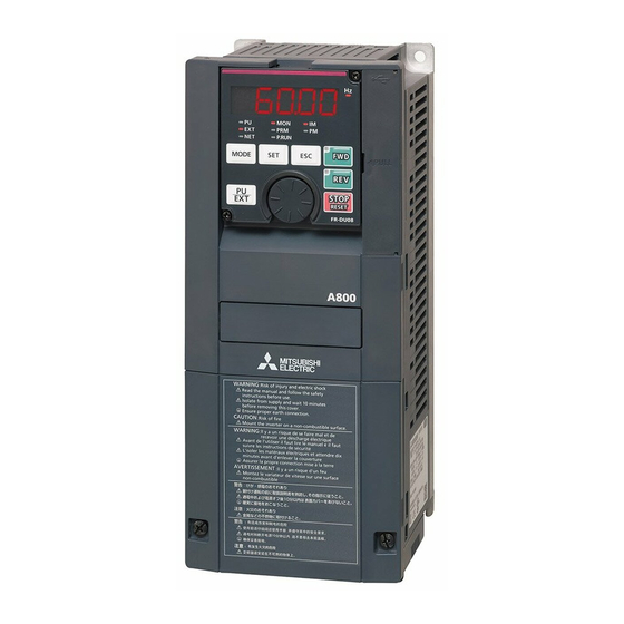
- Page 16 操作パネル (FR-DU08) モータを動かしてみましょう 操作パネル (FR-DU08) 6.1.1 操作パネル (FR-DU08) の各部の名称 操作部 名称 内容 PU: PU 運転モード時に点灯します。 EXT: 外部運転モード時に点灯します。 (初期設定時は、電源 ON すると点灯します。 ) 運転モード表示 NET: ネットワーク運転モード時に点灯します。 PU、EXT: 外部 /PU 併用運転モード 1、2 時に点灯します。 MON: モニタモード時に点灯します。保護機能動作時に早く 2 回点滅します。 操作パネル状態表示 ディスプレイオフモード時にゆっくり点滅します。 PRM: パラメータ設定モード時に点灯します。 IM: 誘導モータ制御設定時に点灯します。 制御モータ表示 PM: PM センサレスベクトル制御設定時に点灯します。 テスト運転を選択したときは点滅します。 周波数単位表示 周波数を表示する時に点灯します。 (設定周波数モニタ表示時は点滅します。 ) 周波数、パラメータ番号などを表示します。...
- Page 17 操作パネル (FR-DU08) 6.1.2 基本操作(出荷設定時) 運転モー ド切換/周波数設定 外部運転モー ド ∗1 (電源投入時) PU運転モー ド ∗1 PUJOG運転モー ド ∗1 フ リ ッカー (例) 数値変更 周波数設定が書込み完了 ! ! 出力電流モニタ ∗2 出力電圧モニタ ∗2 出力周波数モニタ (電源投入時) ∗2 現在設定値 を表示 パラ メ ータ設定モー ド フ リ ッカー (例) パラメータ書込み完了...
- Page 18 パラメータ一覧 パラメータ一覧 インバータの単純な可変速運転は、初期設定値のままで運転ができるようになっています。負荷や運転仕様に合わせて必要なパラメータを設定してください。 パラメータの設定、変更および確認は操作パネル (FR-DU08) で行うことができます。 名 称 設定範囲 初期値 名 称 設定範囲 初期値 名 称 設定範囲 初期値 減速時基準値 0 〜 400%, 9999 9999 端子 4 周波数設定ゲイ 126 0 〜 590Hz 60/50Hz 6/4/3/2/ ン周波数 昇降機モード始動周波数 0 〜 10Hz, 9999 9999 0 トルクブースト 0 〜...
- Page 19 パラメータ一覧 名 称 設定範囲 初期値 名 称 設定範囲 初期値 名 称 設定範囲 初期値 RS-485 通信チェック 0 〜 999.8s, 0 〜 500A, 9999 0 〜 8, 10 〜 20, RUN 端子機能選択 時間間隔 9999 第 2 モータ励磁電流 9999 0 〜 3600A, 22, 25 〜 28, 30 RS-485 通信待ち時間設定 0 〜 150ms, 9999 9999 9999 ...
- Page 20 パラメータ一覧 名 称 設定範囲 初期値 名 称 設定範囲 初期値 名 称 設定範囲 初期値 出力中断検出時間 0 〜 3600s, 9999 1s モータ Ld 減衰率 0 〜 100%, 9999 9999 トルク設定フィルタ 1 0 〜 5s, 9999 9999 出力中断検出レベル 0 〜 590Hz モータ Lq 減衰率 0 〜 100%, 9999 9999 トルク検出フィルタ 1 0 〜...
- Page 21 パラメータ一覧 名 称 設定範囲 初期値 名 称 設定範囲 初期値 名 称 設定範囲 初期値 1006 時計(西暦) 2000 〜 2099 2000 1140 第 2PID 目標値 / 偏差 端子 2 周波数設定バイ 1 〜 5 (902) 入力選択 0 〜 300% 101 〜 131, 201 〜 アス 229, 301 〜 331, 1141 第...
- Page 22 パラメータ一覧 名 称 設定範囲 初期値 1288 近点ドグ後移動量上位 4 桁 0 〜 9999 1289 原点復帰押当てトルク 0 〜 200% 1290 原点復帰押当て待ち時間 0 〜 10s 0.5s 1292 位置制御端子入力選択 0, 1 1293 ロール送りモード選択 0, 1 1294 位置検出下位 4 桁 0 〜 9999 1295 位置検出上位 4 桁 0 〜 9999 1296 位置検出選択 0 〜 2 1297 位置検出ヒステリシス幅...
- Page 23 保護機能のリセット方法 異常とその対策について インバータに異常(重故障)が発生すると保護機能が動作し、アラーム停止して PU の表示部が ページのエラー(異常)表示に自動的に切り換わります。 万一、下記のいずれにも該当しない場合、およびその他にお困りの点がございましたら、お買上店または当社営業所までご連絡ください。 • 異常出力信号の保持 保護機能が動作したとき、インバータの入力側に設けた電磁接触器 (MC) を開路させると、インバータの制御電源がなくなり、異常出力は保持されませ ん。 • 異常表示 保護機能が動作すると、操作パネル表示部が自動的に切り換わります。 • リセット方法 保護機能が動作すると、インバータ出力停止状態を保持しますので、リセットしない限り再始動できません。 (22 ページ参照) • 保護機能が動作したときは、原因の処置を行ってから、インバータをリセットして、運転を再開してください。インバータが故障・破損する可能性があり ます。 インバータの異常表示には、大きく分けて下記のものがあります。 • エラーメッセージ 操作パネル(FR-DU08)やパラメータユニット(FR-PU07)による操作ミスや、設定ミスをメッセージ表示します。インバータは出力遮断しません。 • 警報 操作パネルに表示しても、インバータは出力遮断しませんが、対策しないと重故障が発生する可能性があります。 • 軽故障 インバータは出力遮断しません。パラメータ設定にて軽故障信号を出力することもできます。 • 重故障 保護機能動作にてインバータを出力遮断し、異常出力します。 NOTE • 異常表示の詳細や、その他トラブルについては、 取扱説明書(詳細編)を参照してください。...
- Page 24 異常表示一覧 異常表示一覧 操作パネル表示 名称 操作パネル表示 名称 E. SOT 脱調検出 Eーーーー アラーム履歴 E.LF 出力欠相 HOLD 操作パネルロック E.OHT 外部サーマル動作 LOCD パスワード設定中 E.PTC PTC サーミスタ動作 エ ラ Er1 〜 Er4 E.OPT オプション異常 パラメータ書込みエラー | メ ッ E.OP1 〜 E.OP3 通信オプション異常 セ | ジ rE1 〜 rE4 E. 1 〜...
- Page 25 定格 仕 様 定格 200V クラス 0.4K 0.75K 1.5K 2.2K 3.7K 5.5K 7.5K 15K 18.5K 22K 形名 FR-A820-[] 00046 00077 00105 00167 00250 00340 00490 00630 00770 00930 01250 01540 01870 02330 03160 03800 04750 0.75 18.5 90/110 132 0.75 18.5 適用モータ容...
- Page 26 定格 400V クラス 0.4K 0.75K 1.5K 2.2K 3.7K 5.5K 7.5K 11K 15K 18.5K 22K 30K 37K 45K 55K 75K 90K 110K 132K 160K 185K 220K 250K 280K 形名 FR-A840-[] 00023 00038 00052 00083 00126 00170 00250 00310 00380 00470 00620 00770 00930 01160 01800 02160 02600 03250 03610 04320 04810 05470 06100 06830 0.75 1.5 18.5 22 110 132 160 185 220 250 280 315 355...
- Page 27 付録 付録 1 欧州指令に対するための注意事項 欧州指令とは、EU 加盟国の国別の規制を統一し、EU 内で安全性が保証された製品の流通を円滑にする目的で発行された指令です。 1996 年に欧州指令の一つである EMC 指令への適合証明が法的に義務付けられています。また、1997 年からは欧州指令の一つである低電圧指令への適合も 法的に義務付けられています。EMC 指令および低電圧指令に適合していると製造者が認める製品には、製造者が自ら適合を宣言し、 CE マーク を表示す る必要があります。 • EU 域内販売責任者 EU 域内販売責任者は下記の通りです。 会社名 : Mitsubishi Electric Europe B.V. 住所 : Gothaer Strasse 8, 40880 Ratingen, Germany • 注意事項 本インバータは、EMC 指令について、工業環境下での適合を宣言し、 CE マーク を表示しています。住環境でご使用の際には、ユーザにおいて適切 な対策を実施し、住環境下での適合を確認してください。 EMC 指令について 本インバータは、EMC 指令への適合を自己宣言し、 CE マーク を表示しています。...
- Page 28 環境(詳細は ページ参照) 運転中 保 存 輸送中 LD、ND(初期設定) 、HD: − 10 〜+ 50 ℃ 周囲温度 − 20 〜+ 65 ℃ − 20 〜+ 65 ℃ SLD: − 10 〜+ 40 ℃ 湿度 95%RH 以下 95%RH 以下 95%RH 以下 標高 2500m 2500m 10000m 配線保護について クラス...
- Page 29 付録 2 UL 、 cUL についての注意事項 (準拠規格 UL 508C, CSA C22.2 No.14) 据付け 盤内使用の製品として認定を取得しています。 インバータの周囲温度、湿度、雰囲気が仕様を満足するように盤を設計してください。 (3 ページ参照) 配線保護について アメリカ合衆国内に設置する場合は National Electrical Code および現地の規格に従って、クラス T、クラス J、クラス CC、クラス L タイプのヒュー ズまたは UL489 配線用遮断器(MCCB)を使用してください。 カナダ国内に設置する場合は Canadian Electrical Code および現地の規格に従って、クラス T、クラス J、クラス CC、クラス L タイプのヒューズまた は UL489 配線用遮断器(MCCB)を使用してください。 FR-A820 シリーズの場合は、クラス T、クラス J、クラス CC タイプのヒューズまたは、UL489 配線用遮断器(MCCB)を使用してください。 0.4K 0.75K 1.5K 2.2K 3.7K...
- Page 30 モータ過負荷保護 モータ過負荷保護として電子サーマル機能を使用する場合は、Pr.9 電子サーマルにモータ定格電流を設定してください。 電子サーマル動作特性 モータの過負荷(過熱)を検出し、インバータの出力トランジスタの動作を 止め出力停止します。 (動作特性を左図に示します) Pr. 9=インバータ定格 Pr. 9=インバータ定格の の50%設定 ∗1, 2 100%設定 ∗2 • 三菱製定トルクモータを使用する場合 30Hz以上 ∗3 (1) Pr.71 = 1、13 〜 16、50、53、54 に設定してください。 (低速 30Hz 以上 20Hz ∗3 ・ 動作領域 域で 100%連続トルク特性になります。 ) 10Hz 20Hz 特性曲線より右の領域 10Hz ・ 不動作領域 (2) Pr.9 にモータの定格電流を設定します。...
- Page 31 「保証について」 ご使用に際しましては、以下の製品保証内容をご確認いただきますよう、よろしくお願いいたします。 1. 無償保証期間と無償保証範囲 無償保証期間中に、製品に当社側の責任による故障や瑕疵(以下併せて「故障」と呼びます)が発生した場合、当社はお買い上げいただきました販売店ま たは当社サービス会社を通じて、無償で製品を修理させていただきます。ただし、国内および海外における出張修理が必要な場合は、技術者派遣に要する 実費を申し受けます。また、故障ユニットの取替えに伴う現地再調整・試運転は当社責務外とさせていただきます。 【無償保証期間】 製品の無償保証期間は、お客様にてご購入後またはご指定場所に納入後12ヶ月とさせていただきます。 ただし、当社製品出荷後の流通期間を最長6ヶ月として、製造から18ヶ月を無償保証期間の上限とさせていただきます。また、修理品の無償保証期間は、 修理前の無償保証期間を超えて長くなることはありません。 【無償保証範囲】 (1) 一次故障診断は、原則として貴社にて実施をお願い致します。 ただし、貴社要請により当社、または当社サービス網がこの業務を有償にて代行することができます。 この場合、故障原因が当社側にある場合は無償と致します。 (2) 使用状態・使用方法、および使用環境などが、取扱説明書、ユーザーズマニュアル、製品本体注意ラベルなどに記載された条件・注意事項などにし たがった正常な状態で使用されている場合に限定させていただきます。 (3) 無償保証期間内であっても、以下の場合には有償修理とさせていただきます。 • お客様における不適切な保管や取扱い、不注意、過失などにより生じた故障およびお客様のハードウェアまたはソフトウェア設計内容に起因した 故障。 • お客様にて当社の了解なく製品に改造などの手を加えたことに起因する故障。 • 当社製品がお客様の機器に組み込まれて使用された場合、 お客様の機器が受けている法的規制による安全装置または業界の通念上備えられている べきと判断される機能・構造などを備えていれば回避できたと認められる故障。 • 取扱説明書などに指定された消耗部品が正常に保守・交換されていれば防げたと認められる故障。 • 消耗部品(コンデンサ、冷却ファンなど)の交換。 • 火災、異常電圧などの不可抗力による外部要因および地震、雷、風水害などの天変地異による故障。 • 当社出荷当時の科学技術の水準では予見できなかった事由による故障。 • その他、当社の責任外の場合またはお客様が当社責任外と認めた故障。 2....
- Page 32 同梱 CD-ROM について 同梱 CD-ROM 内には、本製品に関わる各種取扱説明書の PDF が収録されています。 同梱 CD-ROM をご使用になる前に • 同梱 CD-ROM は、三菱電機株式会社の著作物であり、これらに関する著作権その他の権利は、すべて三菱電機株式会社に帰属します。 • 同梱 CD-ROM の一部または全部を、当社の許諾なしに無断で使用、複製することはその形態を問わず禁じます。 • 同梱 CD-ROM は、改良のため予告なく変更することがあります。 • 同梱 CD-ROM を運用した結果による損害、または逸失利益等については、一切の責任を負いかねますので、あらかじめご了承ください。 • Microsoft、Windows、および Internet Explorer は、Microsoft Corporation の米国およびその他の国における登録商標です。 Adobe および Adobe Reader は、Adobe Systems Incorporated の登録商標です。 Pentium は、Intel Corporation の米国およびその他の国における登録商標です。 その他の記載してある会社名、製品名は、各社の商標または登録商標です。 • 保証について 同梱 CD-ROM および関連資料に欠陥があった場合に対しての保証はいたしておりません。 NOTE •...
- Page 33 MEMO...
- Page 34 FR-A800 取扱説明書(詳細編)ご要求用紙 取扱説明書(詳細編)は同梱CD-ROM内のPDFデー タでご覧いただ く こ とがで き ます。 ま た、 三菱電機FAサイ ト からPDFデー タのダウ ン ロー ド も可能です。 www.MitsubishiElectric.co.jp/fa 印刷物のご要求に当たっ ては、この要求用紙を切 り 取 り 、ご連絡先等を必ず記入いただいたのち、下記の送信先まで ∗1 FAXいただければ、直接発送いた し ます。 (本紙にご記入いただいた) お客様の個人情報は、 適切に管理し、 当社が取 り 扱う 商品 ・ サー ビスお よ び関連するサー ビス...
- Page 35 取扱説明書(詳細編)ご要求FAX番号 050-3737-0441 *おかけ間違いのないように、FAX番号をよくお確かめください。 改 訂 履 歴 *取扱説明書番号は、本説明書の裏表紙の左下に記載してあります。 * 印刷日付 改 訂 内 容 取扱説明書番号 2013 年 5 月 IB( 名 )-0600493-A 初版印刷 追加 2013 年 12 月 IB( 名 )-0600493-B ・FR-A840-110K(03250) 〜 280K(06830) 追加 2014 年 4 月 IB( 名 )-0600493-C ・モータ過負荷耐量レベル(Pr.607、Pr.608) 追加 2014 年...
- Page 36 ●アフターサービスネットワーク 三菱電機システムサービス株式会社が24時間365日受付体制でお応えします。 ●サービス網一覧表(三菱電機システムサービス株式会社) ●24時間受付サービス拠点 時間外修理受付窓口 サービス拠点名 番号 住所 電話番号 ファックス専用 【機器全般】*2 北日本支社 〒983-0013 宮城県仙台市宮城野区中野1-5-35 (022)353-7814 (022)353-7834 北海道支店 〒004-0041 北海道札幌市厚別区大谷地東2-1-18 (011)890-7515 (011)890-7516 東京機電支社 〒108-0022 東京都港区海岸3-19-22(三菱倉庫芝浦ビル) (03)3454-5521 (03)5440-7783 神奈川機器サービスステーション 〒224-0053 神奈川県横浜市都筑区池辺町3963-1 (045)938-5420 (045)935-0066 関越機器サービスステーション 〒338-0822 埼玉県さいたま市桜区中島2-21-10 (048)859-7521 (048)858-5601 新潟機器サービスステーション 〒950-0087 新潟県新潟市中央区東大通2-4-10日本生命ビル6F (025)241-7261 (025)241-7262 中部支社...
- Page 37 〒100−8310 東京都千代田区丸の内2-7-3(東京ビル) お問合せは下記へどうぞ 本社....〒100-8310 東京都千代田区丸の内2-7-3(東京ビル7階)............................(03)3218-6721 北海道支社..〒060-8693 北海道札幌市中央区北2条西4丁目1(北海道ビル)..........................(011)212-3793 東北支社..〒980-0011 宮城県仙台市青葉区上杉1-17-7(仙台上杉ビル)..........................(022)216-4546 関越支社..〒330-6034 埼玉県さいたま市中央区新都心11番地2(明治安田生命さいたま新都心ビル ランド・アクシス・タワー 34階)...(048)600-5845 新潟支店..〒950-8504 新潟県新潟市中央区東大通2-4-10(日本生命ビル)..........................(025)241-7227 神奈川支社..〒220-8118 神奈川県横浜市西区みなとみらい2-2-1(横浜ランドマークタワー 18階).................(045)224-2623 北陸支社..〒920-0031 石川県金沢市広岡3-1-1(金沢パークビル)..............................(076)233-5502 中部支社..〒451-8522 愛知県名古屋市西区牛島町6番1号(名古屋ルーセントタワー) ....................(052)565-3323 豊田支店..〒471-0034 愛知県豊田市小坂本町1-5-10(矢作豊田ビル)............................(0565)34-4112 関西支社..〒530-8206 大阪府大阪市北区大深町4番20号(グランフロント大阪 タワー A) ................... ( 06)6486-4119 中国支社..〒730-8657 広島県広島市中区中町7-32(ニッセイ広島ビル)...........................(082)248-5345 四国支社..〒760-8654 香川県高松市寿町1-1-8(日本生命高松駅前ビル)..........................(087)825-0055 九州支社..〒810-8686 福岡県福岡市中央区天神2-12-1(天神ビル)............................(092)721-2236 三菱電機FA機器電話, FAX技術相談 ●電話技術相談窓口 ※1 受付時間 月曜〜金曜 9:00〜19:00、土曜・日曜・祝日 9:00〜17:00 対象機種...
-
Page 38: Table Of Contents
INVERTER A800 FR-A820-00046(0.4K)-04750(90K) FR-A840-00023(0.4K)-06830(280K) INSTRUCTION MANUAL (STARTUP) (ENGLISH) ─CONTENTS─ INVERTER INSTALLATION AND PRECAUTIONS ............3 OUTLINE DIMENSIONS ....................4 WIRING........................... 5 FAILSAFE SYSTEM WHICH USES THE INVERTER ..........13 PRECAUTIONS FOR USE OF THE INVERTER ............14 DRIVE THE MOTOR ....................15 TROUBLESHOOTING ....................23 SPECIFICATIONS...................... - Page 39 Fire Prevention Caution Test run Inverter must be installed on a nonflammable wall without holes (so that Before starting operation, each parameter must be confirmed and nobody touches the inverter heatsink on the rear side, etc.). Mounting it to adjusted.
-
Page 40: Inverter Installation And Precautions
INVERTER INSTALLATION AND PRECAUTIONS Inverter model FR - A8 0 00046 Symbol Voltage class Symbol Description Symbol Type∗1 Circuit board coating Symbol Plated conductor (conforming to IEC60721-3-3 3C2/3S2) 00023 to 06830 Inverter SLD rated current (A) 200 V class 400 V class 0.4 to 280K Inverter ND rated capacity (kW) -
Page 41: Outline Dimensions
OUTLINE DIMENSIONS FR-A820-00046(0.4K) to 04750(90K) FR-A840-04320(160K) to 06830(280K) FR-A840-00023(0.4K) to 03610(132K) 3-φC 2-φC (Unit: mm) 200 V class Inverter model FR-A820-00046(0.4K) FR-A820-00077(0.75K) FR-A820-00105(1.5K) FR-A820-00167(2.2K) FR-A820-00250(3.7K) FR-A820-00340(5.5K) FR-A820-00490(7.5K) FR-A820-00630(11K) FR-A820-00770(15K) FR-A820-00930(18.5K) FR-A820-01250(22K) FR-A820-01540(30K) FR-A820-01870(37K) FR-A820-02330(45K) FR-A820-03160(55K) FR-A820-03800(75K) FR-A820-04750(90K) 400 V class Inverter model FR-A840-00023(0.4K) FR-A840-00038(0.75K) -
Page 42: Wiring
Terminal connection diagrams WIRING Terminal connection diagrams FM type FR-A820-00770(15K) to 01250(22K), FR-A840-00470(18.5K) to 01800(55K) DC reactor Brake resistor∗8 (FR-HEL)∗1 Brake resistor Brake unit DC reactor (Option) (FR-ABR)∗7∗8 (FR-HEL)∗1 Sink logic Brake unit Jumper (Option) Main circuit terminal Earth ∗9 (Ground) Control circuit terminal... - Page 43 Terminal connection diagrams CA type FR-A820-00770(15K) to 01250(22K), FR-A840-00470(18.5K) to 01800(55K) DC reactor Brake resistor∗8 (FR-HEL)∗1 Brake resistor Brake unit DC reactor (FR-ABR)∗7∗8 (Option) (FR-HEL)∗1 Sourse logic Brake unit Jumper (Option) Main circuit terminal Earth ∗9 (Ground) Control circuit terminal Jumper Jumper Earth...
- Page 44 Main circuit terminals Main circuit terminals Terminal arrangement and wiring FR-A820-00046(0.4K), 00077(0.75K) FR-A820-00105(1.5K) to 00250(3.7K) FR-A820-00340(5.5K), 00490(7.5K) FR-A840-00023(0.4K) to 00126(3.7K) FR-A840-00170(5.5K), 00250(7.5K) P/+ PR Jumper Jumper R1/L11 S1/L21 Jumper Jumper R/L1 S/L2 T/L3 Jumper R/L1 S/L2 T/L3 P/+ PR Jumper R/L1 S/L2 T/L3 R1/L11 S1/L21...
- Page 45 Main circuit terminals Cable gauge of main circuit terminals and earth (ground) terminals Use an appropriate cable gauge to suppress the voltage drop to 2% or less. If the wiring distance is long between the inverter and motor, the voltage drop in the main circuit will cause the motor torque to decrease especially at a low speed. The following table indicates a selection example for the wiring length of 20 m.
- Page 46 Main circuit terminals Total wiring length With general-purpose motor Connect one or more general-purpose motors within the total wiring length shown in the following table. (The wiring length should be 100 m or less under vector control.) Pr.72 setting FR-A820-00046(0.4K), FR-A820-00077(0.75K), FR-A820-00105(1.5K) or higher,...
- Page 47 Control circuit terminal Control circuit terminal Terminal layout ∗1 1 F/C +24 SD So SOC S1 S2 PC Recommended cable gauge: 0.3 to 0.75 mm 5 10E 10 SE SE SU IPF OL FU PC RL RM RH RT AU STP MRS RES SD SD STF STR JOG...
- Page 48 Control circuit terminal • Wire removal Pull the wire while pushing the open/close button all the way down firmly with a flathead screwdriver. Open/close button Flathead screwdriver NOTE • When using stranded wires without a blade terminal, twist enough to avoid short circuit with a nearby terminals or wires. •...
- Page 49 Safety stop function Safety stop function Function description The terminals related to the safety stop function are shown below. Terminal Terminal function description symbol For input of the safety stop channel 1. Open between S1 and SIC, and between S2 and SIC: ...
-
Page 50: Failsafe System Which Uses The Inverter
Safety stop function If any of the protective functions shown in the following table is activated, the terminal SO turns OFF. Operation panel Operation panel Error definition Error definition indication indication Option fault E.OPT Overspeed occurrence E.OS Communication option fault E.OP1 to E.OP3 Speed deviation excess detection E.OSD... -
Page 51: Precautions For Use Of The Inverter
PRECAUTIONS FOR USE OF THE INVERTER The FR-A800 series inverter is a highly reliable product, but incorrect peripheral circuit making or operation/handling method mayshorten the product life or damage the product. Before starting operation, always recheck the following points. • Use crimping terminals with insulation sleeves to wire the power supply and the motor. -
Page 52: Drive The Motor
Operation panel (FR-DU08) DRIVE THE MOTOR Operation panel (FR-DU08) 6.1.1 Components of the operation panel (FR-DU08) Component Name Description PU: ON to indicate the PU operation mode. EXT: ON to indicate the External operation mode. (ON at power-ON in the initial setting.) Operation mode indicator NET: ON to indicate the Network operation mode. - Page 53 Operation panel (FR-DU08) 6.1.2 Basic operation (factory setting) Operation mode switchover/Frequency setting External operation mode ∗1( At power-ON) PU Jog operation mode ∗1 ∗1 PU operation mode Flicker (Example) Frequency setting has been Value change written and completed!! Output current monitor ∗2 Output voltage monitor ∗2...
- Page 54 Parameter list Parameter list For simple variable-speed operation of the inverter, the initial values of the parameters may be used as they are. Set the necessary parameters to meet the load and operational specifications. Parameter setting, change and check can be performed from the operation panel (FR-DU08). Setting Initial Setting...
- Page 55 Parameter list Setting Initial Setting Initial Setting Initial Name Name Name range value range value range value PID action set point 0 to 100%, 9999 9999 STF terminal function Monitor decimal digits 0, 1, 9999 9999 selection selection 0.01 to 10s, PID differential time 9999 9999...
- Page 56 Parameter list Setting Initial Setting Initial Setting Initial Name Name Name range value range value range value Creep speed 0 to 10Hz 0.5Hz 0, 1, 3 to 6, Fourteenth target 13 to 16, 20, 23, position upper 4 digits Creep switchover 0 to 16383 ...
- Page 57 Parameter list Setting Initial Setting Initial Setting Initial Name Name Name range value range value range value First free thermal 0 to 590Hz, Maintenance timer 3 0(1 to 9998) Operation panel 1 to 3, 5 to 14, 9999 9999 reduction frequency 2 9999 monitor selection 1 17 to 20, 22 to 36,...
- Page 58 Parameter list Setting Initial Setting Initial Setting Initial Name Name Name range value range value range value Fall-time torque bias FM/CA terminal 101 to 131, 0 to 400%, 9999 9999 ― ― terminal 1 gain (900) calibration 201 to 229, ...
- Page 59 Parameter list Setting Initial Setting Initial Setting Initial Name Name Name range value range value range value Swinging suppression Fourth positioning dwell Home position return 1076 0 to 3 1236 0 to 20000ms 1284 0 to 10Hz 0.5Hz width time creep speed 1077 Rope length...
-
Page 60: Troubleshooting
Reset method for the protective functions TROUBLESHOOTING When a fault occurs in the inverter, the protective function activates, and the PU display automatically changes to one of the fault or alarm indications on page If the fault does not correspond to any of the following faults or if you have any other problem, please contact your sales representative. •... - Page 61 List of fault displays List of fault displays Operation panel indication Name Operation panel indication Name E. SOT Loss of synchronism detection E- - - - Faults history E.LF Output phase loss HOLD Operation panel lock E.OHT External thermal relay operation LOCD Password locked E.PTC...
-
Page 62: Specifications
Rating SPECIFICATIONS Rating 200 V class 00046 00077 00105 00167 00250 00340 00490 00630 00770 00930 01250 01540 01870 02330 03160 03800 04750 Model FR-A820-[ ] 0.4K 0.75K 1.5K 2.2K 3.7K 5.5K 7.5K 18.5K 0.75 18.5 90/110 132 0.75 18.5 Applicable motor capacity (kW) ... - Page 63 Rating 400 V class 00023 00038 00052 00083 00126 00170 00250 00310 00380 00470 00620 00770 00930 01160 01800 02160 02600 03250 03610 04320 04810 05470 06100 06830 Model FR-A840-[ ] 0.4K 0.75K 1.5K 2.2K 3.7K 5.5K 7.5K 11K 15K 18.5K 22K 30K 37K 45K 55K 75K 90K 110K 132K 160K 185K 220K 250K 280K 0.75 1.5 18.5 22 110 132 160 185 220 250 280 315 355...
- Page 64 Directive, the manufacturer must declare the conformity and affix the CE marking. • The authorized representative in the EU The authorized representative in the EU is shown below. Name: Mitsubishi Electric Europe B.V. Address: Gothaer Strasse 8, 40880 Ratingen, Germany • Note We declare that this inverter conforms with the EMC Directive in industrial environments and affix the CE marking on the inverter.
- Page 65 The operating capacity of the relay outputs (terminal symbols A1, B1, C1, A2, B2 and C2) should be 30 VDC, 0.3 A. (Relay output has basic isolation from the inverter internal circuit.) Control circuit terminals on page 5 are safely isolated from the main circuit.
- Page 66 Appendix 2 Instructions for UL and cUL (Standard to comply with: UL 508C, CSA C22.2 No.14) General precaution CAUTION - Risk of Electric Shock - The bus capacitor discharge time is 10 minutes. Before starting wiring or inspection, switch power off, wait for more than 10 minutes, and check for residual voltage between terminal P/+ and N/- with a meter etc., to avoid a hazard of electrical shock.
- Page 67 Motor overload protection When using the electronic thermal relay function as motor overload protection, set the rated motor current in Pr.9 Electronic thermal O/L relay. Operation characteristics of electronic thermal relay function This function detects the overload (overheat) of the motor, stops the operation of the inverter's output transistor, and stops the output.
- Page 68 The copyright and other rights of the enclosed CD-ROM all belong to Mitsubishi Electric Corporation. No part of the enclosed CD-ROM may be copied or reproduced without the permission of Mitsubishi Electric Corporation. Specifications of the enclosed CD-ROM are subject to change for modification without notice.
- Page 69 WARRANTY When using this product, make sure to understand the warranty described below. 1. Warranty period and coverage We will repair any failure or defect (hereinafter referred to as "failure") in our FA equipment (hereinafter referred to as the "Product") arisen during warranty period at no charge due to causes for which we are responsible through the distributor from which you purchased the Product or our service provider.
- Page 70 REVISIONS *The manual number is given on the bottom left of the back cover. Print date *Manual number Revision May 2013 IB-0600493-A First edition Addition Nov. 2013 IB-0600493-B • FR-A840-03250(110K) to 06830(280K) Addition Apr. 2014 IB-0600493-C • Motor permissible load level (Pr.607, Pr.608) Addition Sep.
- Page 71 HEADQUARTERS EUROPEAN REPRESENTATIVES EUROPEAN REPRESENTATIVES EUROPEAN REPRESENTATIVES MITSUBISHI ELECTRIC EUROPE GEVA AUSTRIA MITSUBISHI ELECTRIC IRELAND Beijer Electronics AB SWEDEN EUROPE B.V. Wiener Straße 89 EUROPE B.V.-Irish Branch Box 426 German Branch A-2500 Baden Westgate Business Park S-20123 Malmö Gothaer Straße 8...
- Page 72 三菱通用变频器 A800 FR-A820-00046(0.4K)-04750(90K) FR-A840-00023(0.4K)-06830(280K) 使用手册 (导入篇) (中文) ─目 录─ 变频器的安装和注意事项 .......... 3 外形尺寸图 ............4 接线 ............5 关于使用变频器的故障自动保险系统 ....... 13 变频器使用上的注意事项 ......... 14 电机运行 ............15 故障及其对策 ........... 22 规 格 ............24 本使用手册 (导入篇)将对本产品的使用及注意点进行说 防止触电 明。 警告 此外,请务必将本使用手册 (导入篇)送至使用本产品的客...
- Page 73 防止火灾 警告 注意 操作方法 变频器请安装在无孔的不可燃壁上 (避免从背后触及变频器散热 一旦选择了再试功能 , 跳闸时会突然再启动 , 请远离设备。 片) 。直接安装在易燃物上或靠近易燃物品 , 会导致火灾。 变频器发生故障时,请将变频器的电源断开。若持续地流过大电 根据功能设定状态,即使按下按键后,有时输出也不会停 流 , 会导致火灾。 止。 请单独准备紧急停止回路 (电源切断及用于紧急停止的机 使用制动电阻器时,请用异常信号切断电源。否则可能由于制动 械制动动作等)和急停开关。 晶体管的故障等导致制动电阻器异常发热,从而可能引起火灾。 复位变频器报警前请确认运行信号断开,否则电机会突然恢复启 请不要在直流端子 P/+,N/- 上直接连接电阻,这样会导致火灾。 动。 否则会导致触电。 ...
-
Page 74: 变频器的安装和注意事项
变频器的安装和注意事项 变频器型号 ∗1 ∗2 根据类型不同规格不同。主要的差异如下表所示。 初始设定 机种 监视输出 内置 EMC 滤波器 控制逻辑 额定频率 Pr.19 基底频率电压 端子 FM: 脉冲列输出 FM( 搭载端子 FM 的产品 ) 漏型逻辑 60Hz 9999( 与电源电压相同 ) 端子 AM: 模拟电压输出 (DC0 ~ ±10V) 端子 CA: 模拟电流输出 (DC0 ~ 20mA) CA( 搭载端子... -
Page 75: 外形尺寸图
外形尺寸图 φ φ ( 单位 :mm) 200V 等级 变频器型号 FR-A820-00046(0.4K) FR-A820-00077(0.75K) FR-A820-00105(1.5K) FR-A820-00167(2.2K) FR-A820-00250(3.7K) FR-A820-00340(5.5K) FR-A820-00490(7.5K) FR-A820-00630(11K) FR-A820-00770(15K) FR-A820-00930(18.5K) FR-A820-01250(22K) FR-A820-01540(30K) FR-A820-01870(37K) FR-A820-02330(45K) FR-A820-03160(55K) FR-A820-03800(75K) FR-A820-04750(90K) 400V 等级 变频器型号 FR-A840-00023(0.4K) FR-A840-00038(0.75K) FR-A840-00052(1.5K) FR-A840-00083(2.2K) FR-A840-00126(3.7K) FR-A840-00170(5.5K) FR-A840-00250(7.5K) FR-A840-00310(11K) FR-A840-00380(15K) FR-A840-00470(18.5K) FR-A840-00620(22K) FR-A840-00770(30K) - Page 76 端子接线图 接线 端子接线图 FM 类型 ∗8 ∗ ∗ ∗1 ∗ ∗9 ∗ ∗ ∗ ∗ ∗ ∗ ∗ ∗ ∗ ∗ ∗ ∗ FR-A820-03800(75K) 及以上、FR-A840-02160(75K) 及以上或使用 75kW 及以上的电机时必须连接选件的直流电抗器 (FR-HEL) 。 (直流电抗器请参照第 24 页,根据适 用电机容量进行选定。 ) FR-A820-03160(55K) 及以下、FR-A840-01800(55K) 及以下连接直流电抗器的情况下,端子 P1 与 P/+ 间安装有短路片时,请先拆下短路片再安装直流电抗器。 制动回路用另外的电源时...
- Page 77 端子接线图 CA 类型 ∗8 ∗1 ∗ ∗ ∗ ∗9 ∗ ∗ ∗ ∗ ∗ ∗ ∗ ∗ ∗ FR-A820-03800(75K) 及以上、FR-A840-02160(75K) 及以上或使用 75kW 及以上的电机时必须连接选件的直流电抗器 (FR-HEL) 。 (直流电抗器请参照第 24 页,根据适 用电机容量进行选定。 ) FR-A820-03160(55K) 及以下、FR-A840-01800(55K) 及以下连接直流电抗器的情况下,端子 P1 与 P/+ 间安装有短路片时,请先拆下短路片再安装直流电抗器。 制动回路用另外的电源时 , 拆下 R1/L11、S1/L21 短路片。 通过输入端子分配...
- Page 78 主回路端子 主回路端子 端子排列和接线 FR-A820-00105(1.5K) ~ 00250(3.7K) FR-A820-00340(5.5K)、00490(7.5K) FR-A820-00046(0.4K)、00077(0.75K) FR-A840-00023(0.4K) ~ 00126(3.7K) FR-A840-00170(5.5K)、00250(7.5K) P/+ PR R1/L11 S1/L21 R/L1 S/L2 T/L3 R/L1 S/L2 T/L3 R/L1 S/L2 T/L3 R1/L11 S1/L21 R1/L11 S1/L21 FR-A820-01540(30K) FR-A820-00630(11K) FR-A820-00770(15K)、01250(22K) FR-A840-00310(11K)、00380(15K) FR-A840-00470(18.5K)、00620(22K) FR-A840-00770(30K) R1/L11 S1/L21 R1/L11 S1/L21 R1/L11 S1/L21 R/L1 S/L2...
- Page 79 主回路端子 主回路端子和接地端子的电线型号等 为使电压下降在 2% 以内,请选用适当型号的电线。 变频器和电机间的接线距离较长时,特别是在低速的情况下,会由于主回路电缆的电压下降而导致电机的转矩下降。 接线长为 20m 的选择示例详见下表。 • 200V 等级 (供电为 220V、过负载电流额定为 150% 1 分时 ) 电线型号 压接端子 紧固 AWG/MCM HIV 电线等 (mm ) PVC 电线等 (mm ) 端子螺丝 变频器的适用型号 转矩 R/L1、 R/L1、 R/L1、 R/L1、 尺寸 P/+、 N·m S/L2、...
- Page 80 主回路端子 总接线长度 感应电机时 连接 1 台或多台电机时 , 其连接线路总长度应低于下表内的值。( 矢量控制时 , 请控制在 100m 以内。) Pr.72 设定值 FR-A820-00046(0.4K)、 FR-A820-00077(0.75K)、 FR-A820-00105(1.5K) 以上、 ( 载波频率 ) FR-A840-00023(0.4K) FR-A840-00038(0.75K) FR-A840-00052(1.5K) 以上 2 (2kHz)以下 300m 500m 500m 3 (3kHz)以上 200m 300m 500m 400V 系列的电机用变频器驱动时,线路参数引起的浪涌电压在电机的端子侧发生,此电压会使电机的绝缘性能降低。这种情况请采取以下任意一项措施。 •...
- Page 81 控制回路端子 控制回路端子 RS-485 端子排列 1 F/C +24 SD So SOC S1 S2 PC 推荐螺丝尺寸 : 0.3 ~ 0.75mm 5 10E 10 SE SE SU IPF OL FU PC RL RM RH RT AU STP MRS RES SD SD STF STR JOG FM 类型时为端子...
- Page 82 控制回路端子 • 拆下电线 使用一字螺丝刀将开关按钮按到底后拔出电线。 NOTE • 用绞合电线直接接线时 , 注意不要与邻近的端子或接线发生短路而应将交合电线磋紧后再进行接线。 • 拆下电线时 , 请务必将开关按钮按到底后拔出,否则可能会损坏端子排。 • 请使用小型一字螺丝刀 ( 刀尖厚度 :0.4mm、刀尖宽度 :2.5mm) 如果使用刀尖宽度窄的一字螺丝刀,端子排可能会损坏。 市场销售品的例子 (2012 年 2 月时) 产品名称 类型 生产厂家 螺丝刀 SZF 0- 0,4 x 2,5 菲尼克斯电气中国公司 • 应将一字螺丝刀垂直对准开关按钮按下。如果刀尖打滑,可能会引起变频器损坏、人身事故。 接线时的注意事项 • 连接控制回路端子的电线建议使用 0.3 ~ 0.75mm 尺寸的电线。...
- Page 83 安全停止功能 安全停止功能 功能说明 有关端子的安全停止功能如下所记。 端子记号 端子功能说明 安全停止系统 1 的输入 在 S1-SIC、S2-SIC 之间 断开:安全停止状态 安全停止系统 2 的输入 短路 : 安全停止状态以外 端子 S1、S2 的公共端子 异常检测、报警输出 OFF: 内部安全回路异常 没有发生内部安全回路异常 时输出 ON : 内部安全回路异常 状态以外 端子 SO( 集电极开路输出 ) 公共端子 初始状态时的端子 S1-PC、S2-PC、SIC-SD,分别通过短路电线接地。使用安全停止功能时 , 请拆下短路用电线 , 按照下图的连接例连接安全继电器。 内部安全回路异常时,在操作面板上显示下一页记载的异常内容的其中一个。...
-
Page 84: 关于使用变频器的故障自动保险系统
安全停止功能 发生下表的任何保护功能时,端子 SO 将置为 OFF。 异常内容 操作面板显示 异常内容 操作面板显示 选件异常 E.OPT 发生过速度 E.OS 通讯选件异常 E.OP1 ~ E.OP3 速度偏差过大检测 E.OSD 变频器参数储存器元件异常 E.PE 断线检测 E.ECT 再试次数溢出 E.RET 位置误差大 E.OD 变频器参数存储器元件异常 E.PE2 制动顺控异常 E.MB1 ~ E.MB7 操作面板用电源短路 /RS-485 端 编码器相位错误 E.EP E.CTE 子用电源短路 E.CPU CPU 错误... -
Page 85: 变频器使用上的注意事项
变频器使用上的注意事项 FR-A800 系列变频器是高可靠性产品。但由于周围回路的错误编排或运行、操作方法不同,产品可能会导致缩短产品寿命或产品破损。运行时请务必注意下列事 项,进行再次确认后使用。 • 电源及电机接线的压装端子,请使用带有绝缘套管的端子。 • 电源一定不能接到变频器输出端 (U、V、W) 上,否则将损坏变频器。请绝对避免此种接线。 • 接线时不要在变频器内留下电线切屑,电线切屑可能会导致异常、故障、错误动作发生。 请保持变频器的清洁。变频器必须始终保持清洁。 在控制柜上钻孔时请务必注意不要使切屑粉掉进变频器内。 • 为使线路电压下降在 2% 以内,请用适当型号的电线接线。 变频器和电机间的接线距离较长时,特别是在低频率输出的情况下,会由于主回路电缆的电压下降而导致电机的转矩下降。 推荐的电缆规格请参照第 8 页。 • 总接线长度在规定的长度以下使用。 特别是进行长距离接线时,受到因接线的寄生电容而产生的充电电流的影响,会有高响应电流限制功能下降,连接在变频器输出侧的机器发生误动作等不良 现象,所以请注意总接线长度。 (第 9 页参照) • 电磁波干扰 变频器输入 / 输出 (主回路)包含有谐波成分,可能干扰变频器附近的通讯设备 (如 AM 收音机) 。因此,安装选件 EMC 滤波器 (EMC 滤波器入切连接器变为... -
Page 86: 电机运行
操作面板 (FR-DU08) 电机运行 操作面板 (FR-DU08) 6.1.1 操作面板 (FR-DU08) 的各部分名称 操作部位 名称 内容 PU: PU运行模式时亮灯。 EXT: 外部运行模式时亮灯。 (初始设定时,电源ON后即亮灯。 ) 显示运行模式 NET: 网络运行模式时亮灯。 PU、EXT:外部/PU组合运行模式1、2时亮灯。 MON: 监视模式时亮灯。保护功能动作时快速地闪烁2次。 显示操作面板状态 显示屏关闭模式时,缓慢地闪烁。 PRM: 参数设定模式时亮灯。 感应电机控制设定时亮灯。 显示控制电机 PM无传感器矢量控制设定时亮灯。 试运行状态选择时闪烁。 显示频率单位 频率显示时亮灯。 (设定频率监视显示时闪烁。 ) 显示频率、参数编号等。 监视器 (5位LED) (通过设定Pr.52、Pr.774~Pr.776,可以变更监视项目。 ) 显示顺控功能有效... - Page 87 操作面板 (FR-DU08) 6.1.2 基本操作 ( 出厂设定值 ) 运行模式的详细内容,请参照使用手册。 可以变更监视内容。 (参照使用手册) 追踪功能的详细内容,请参照使用手册。 报警历史的详细内容,请参照使用手册。 连接 USB 储存器时 , 显示 USB 储存器模式。USB 储存器模式的详细 , 请参照使用手册 ( 详细篇 )。 电机运行...
- Page 88 参数一览表 参数一览表 可以在初始设定值不作任何改变的状态下实现变频器的单纯可变速运行。请根据负荷或运行规格等设定必要的参数。可以通过操作面板 (FR-DU08) 进行参数的设 定、变更及确认操作。 名 称 设定范围 初始值 名 称 设定范围 初始值 名 称 设定范围 初始值 0 ~ 10,101 ~ PID 积分时间 0.1 ~ 3600s,9999 报警发生时再试次数 6/4/3/2/ PID 上限 0 ~ 100%,9999 9999 转矩提升 0 ~ 30% 再试等待时间 0.1 ~...
- Page 89 参数一览表 名 称 设定范围 初始值 名 称 设定范围 初始值 名 称 设定范围 初始值 Soft-PWM 动作选择 通讯错误计数 - 第 2 电机自动调整设定 0,1,11,101 / 状态 模拟输入显示单位切换 0,1 停止位置指令选择 0,1,9999 9999 位置控制紧急停止减速 端子 1 加算补偿量 (端 定向速度 0 ~ 30Hz 0 ~ 360.0s 0 ~...
- Page 90 参数一览表 名 称 设定范围 初始值 名 称 设定范围 初始值 名 称 设定范围 初始值 第 1 自由过热保护低减 第 2 电机惯量 ( 整数部 转矩偏置滤波器 0 ~ 5s,9999 9999 1 ~ 100% 100% 10 ~ 999,9999 9999 率 2 位 ) 转矩偏置动作时间 0 ~ 5s,9999 9999 第...
- Page 91 参数一览表 名 称 设定范围 初始值 名 称 设定范围 初始值 名 称 设定范围 初始值 0 ~ 59,100 ~ 159, 1144 第 2PID 下限 0 ~ 100%,9999 9999 端子 1 偏置频率 (速 (917) 0 ~ 590Hz 200 ~ 259,300 ~ 1145 第 2PID 偏差极限 0 ~...
- Page 92 参数一览表 名 称 设定范围 初始值 1289 原点回归接触转矩 0 ~ 200% 1290 原点回归接触等待时间 0 ~ 10s 0.5s 1292 位置控制端子输入选择 0,1 1293 滚轮送进模式选择 1294 位置检测后 4 位 0 ~ 9999 1295 位置检测前 4 位 0 ~ 9999 1296 位置检测选择 0 ~ 2 1297 位置检测迟滞幅度...
-
Page 93: 故障及其对策
保护功能的复位方法 故障及其对策 如果变频器出现异常 (重故障) ,则保护功能启动,报警停止后 PU 的显示部将自动切换成第 23 页错误 (异常)显示。 万一在下述的任意一项中找不到一致的显示符或有其他困难,请与经销商或本公司联系。 • 异常输出信号的保持 保护功能动作时,如果断开设置在变频器输入侧的电磁接触器 (MC) ,将失去变频器的控制电源,不再保持异常输出。 • 异常显示 保护功能启动后操作面板的显示部分自动切换成异常显示。 • 复位方法 保护功能启动后变频器将持续输出停止状态,所以只有复位才能再启动。 (第 22 页参照) • 保护功能启动时,采取相应的措施,复位变频器,重新启动运行。变频器可能发生故障、损坏。 变频器的异常显示可以分为下述几大类。 • 错误信息 对于操作面板 (FR-DU08)或参数单元 (FR-PU07)的操作错误或设定错误,显示相关信息。变频器不会切断输出。 • 报警 即使在操作面板显示报警,变频器也不会切断输出,但如果不采取措施的话,可能会引发重故障。 • 轻故障 变频器不会切断输出。用参数设定可以输出轻微故障信号。 • 严重故障 保护功能动作,切断变频器输出,输出异常信号。... - Page 94 异常显示一览 异常显示一览 操作面板显示 名称 操作面板显示 名称 E. SOT 失调检测 E---- 报警历史 E.LF 输出缺相 HOLD 操作面板锁定 E.OHT 外部热继电器动作 LOCD 密码设定中 E.PTC PTC 热敏电阻动作 Er1 ~ Er4 E.OPT 选件异常 参数写入错误 错 误 信 E.OP1 ~ E.OP3 通讯选件异常 息 rE1 ~ rE4 E. 1 ~ E. 3 选件异常...
-
Page 95: 规 格
额定 规 格 额定 200V 等级 00046 00077 00105 00167 00250 00340 00490 00630 00770 00930 01250 01540 01870 02330 03160 03800 04750 型号 FR-A820-[] 0.4K 0.75K 1.5K 2.2K 3.7K 5.5K 7.5K 18.5K 0.75 18.5 90/110 132 0.75 18.5 电机的适用容... - Page 96 额定 400V 等级 00023 00038 00052 00083 00126 00170 00250 00310 00380 00470 00620 00770 00930 01160 01800 02160 02600 03250 03610 04320 04810 05470 06100 06830 型号 FR-A840-[] 0.4K 0.75K 1.5K 2.2K 3.7K 5.5K 7.5K 11K 15K 18.5K 22K 90K 110K 132K 160K 185K 220K 250K 280K 0.75 1.5 18.5 22...
- Page 97 1996 年,对欧州指令之一的 EMC 指令的符合证明被赋予了法律义务此外,自 1997 年起,对欧州指令之一的低电压指令的符合也被赋予了法律义务。符合 EMC 指令 以及低电压指令的制造商所认可的产品必须由制造商自己宣布符合,并标注 “CE 标识 ”。 • 欧盟圈内销售负责人 以下为欧盟圈内销售负责人。 公司名称 : Mitsubishi Electric Europe B.V. 地址 : Gothaer 8trasse 8, 40880 Ratingen, Germany • 注意事项 本变频器可在工业环境中使用,符合 EMC 指令,并标有 “CE 标志 ” 。若要在居住环境中使用,则需要用户实施相应措施以确保适合当下居住环境。 关于 EMC 指令...
- Page 98 保护接线 请使用 T 级、J 级、CC 级、L 级的熔丝,或 UL489 接线用断路器 (MCCB) 。 FR-A820 系列时,请使用 T 级、J 级、CC 级的熔丝,或 UL489 接线用断路器 (MCCB) 。 00046 00077 00105 00167 00250 00340 00490 00630 00770 FR-A820-[] (0.4K) (0.75K) (1.5K) (2.2K) (3.7K) (5.5K) (7.5K) (11K) (15K) 熔丝额定电压...
- Page 99 附录 2 UL,cUL 的注意事项 (遵守标准 UL 508C, CSA C22.2 No.14) 安装 作为控制柜内使用的产品取得了认定。 请满足变频器的周围温度、湿度、周围环境等规格,设计控制柜。 (参照第 3 页) 保护接线 在美国设置时,请使用符合 National Electrical Code 及当地规格 , 使用 T 级、J 级、CC 级、L 级的熔丝或 UL489 接线用断路器 (MCCB)。 在加拿大设置时,请使用符合 Canadian Electrical Code 及当地规格 , 使用 T 级、J 级、CC 级、L 级的熔丝或 UL489 接线用断路器 (MCCB)。 FR-A820 系列时,请使用...
- Page 100 电机过负载保护 为进行电机过负载保护使用电子过热保护功能时,请在 Pr.9 电子过热保护 中设定电机额定电流。 电子过热保护的动作特性 检测电机的过负载 (过热) ,中止变频器输出晶体管的动作并停止输出。 (动作特性如左图所示) • 使用三菱制恒转矩电机时 ∗ ∗ (1) 请将 Pr.71 设定为 “1、13 ~ 16、50、53、54”。 (低速区域时呈 100% 连续转矩特性) (2) 在 Pr.9 中设定电机额定电流。 ∗ ∗ 在 Pr.9 中设定了变频器额定电流 50% 的值 (电流值)时。 % 值表示对应于变频器额定输出电流的 %。不是对应于电机额定电流的 %。 设定了三菱恒转矩电机专用的电子过热保护时,在...
- Page 101 「关于保修」 使用本产品时,请确认以下的产品保修内容。 1.免费保修期限与免费保证范围 在免费保修期限内,产品发生因本公司责任引起的故障和瑕疵 (以下统称为“故障”)发生时,本公司将通过您购买产品的销售店或本公司的服务公司,对产 品进行免费修理。但是,需要在国内或海外进行出差修理时,本公司将收取派遣技术人员所需的费用。此外,伴随更换故障模块的现场重新调整、试运行不在 本公司责任范围内。 【免费保修期限】 产品的免费保修期限为客户购买后或交付至指定场所后12个月。 但是,本公司产品出厂后的流通期限最长为6个月,从制造起的18个月为免费保修期限的上 限。此外,修理品的免费保修期限不会超过修理前的免费保修期限。 【免费保修范围】 (1) 首次故障诊断原则上由贵公司实施。 但是,根据贵公司的要求本公司或本公司服务网可以有偿代行此业务。 此时,故障原因在于本公司时,不收取费用。 (2) 仅限定于使用状态、使用方法以及使用环境等遵守使用说明书、用户手册、产品本体注意标签等所记载的条件、注意事项等的正常状态下使用的情况。 (3) 即使在免费保修期内,以下情况为有偿修理。 • 因客户的保管不当和操作、不注意、过失等引起的故障以及客户的硬件或软件设计内容引起的故障。 • 客户在本公司不知情的情况下对产品加以改造等引起的故障。 • 本公司产品组装入客户设备使用时,如果客户设备准备了基于所受法规限制的安全装置或行业普遍认为应准备的功能、构造等就可以回避的故障。 • 通过正常维护、更换使用说明书等规定的消耗部件则可以防止的故障。 • 消耗部件 (电容器、冷却风扇等)的更换。 • 因火灾、异常电压等不可抗力造成的外部因素以及地震、雷电、风灾、水灾等自然灾害引起的故障。 • 以从本公司出厂时的科学技术水平无法预见的原因引起的故障。 • 其他不属于本公司责任或客户认为不属于本公司责任的故障。 2.生产停止后的有偿修理期限 (1) 本公司可受理的有偿的产品修理期限为该产品生产停止后7年内。对于生产停止的有关内容,由本公司销售人员或服务人员等通知。 (2) 生产停止后无法提供产品...
- Page 102 关于附带 CD-ROM 附带 CD-ROM 内收录关于本产品的各种使用手册的 PDF。 使用附带 CD-ROM 之前 • 附带 CD-ROM 是三菱电机株式会社的著作 , 本著作的著作权及其它权利全部归三菱电机株式会社所有。 • 没有本公司的许诺 , 禁止擅自使用或复制附带 CD-ROM 的部分或全部内容。 • 附带 CD-ROM 的内容有因改良而更改的可能 , 恕不预先通知。 • 关于因使用附带 CD-ROM 而造成的损失或逸失利益等,敝公司将不承担一切责任 , 敬请周知。 • Microsoft、Windows、Internet Explorer 是美国 Microsoft Corporation 公司在美国及其它国家的注册商标。 Adobe、Adobe Reader 是...
- Page 103 MEMO...
- Page 104 修 订 记 录 *使用手册编号,本手册的背页左下角有记载。 * 印刷日期 修 订 内 容 使用手册编号 2013 年 5 月 IB( 名 )-0600493-A 初版印刷 追加 2013 年 11 月 IB( 名 )-0600493-B ·FR-A840-03250(110K) ~ 06830(280K) 追加 2014 年 4 月 IB( 名 )-0600493-C · 电机过负载承受量水平 (Pr.607、Pr.608) 追加...
- Page 105 http://cn.MitsubishiElectric.com/fa/zh/...
- Page 106 HEAD OFFICE: TOKYO BUILDING 2-7-3, MARUNOUCHI, CHIYODA-KU, TOKYO 100-8310, JAPAN FR-A800 形 名 取扱説明書(導入編) 形 名 1A2-P50 コード お断りなしに仕様を変更することがありますのでご了承ください Specifications subject to change without notice. IB(名)-0600493-E(1503)MEE Printed in Japan...
Need help?
Do you have a question about the A800 and is the answer not in the manual?
Questions and answers