
Related Manuals for WAGO 750-8207


Summary of Contents for WAGO 750-8207
- Page 1 Manual WAGO-I/O-SYSTEM 750 750-8207(/xxx-xxx) PFC200 CS 2ETH RS 3G PLC - Controller PFC200 Draft version 1.2.1 from 2017-09-13, valid from FW Version 02.06.20(09)
- Page 2 We wish to point out that the software and hardware terms as well as the trademarks of companies used and/or mentioned in the present manual are generally protected by trademark or patent. WAGO is a registered trademark of WAGO Verwaltungsgesellschaft mbH. Manual Draft version 1.2.1 from 2017-09-13, valid from FW Version 02.06.20(09)
-
Page 3: Table Of Contents
Legal Bases ..................19 2.1.1 Subject to Changes ................19 2.1.2 Personnel Qualifications ..............19 2.1.3 Use of the WAGO-I/O-SYSTEM 750 in Compliance with Underlying Provisions ..................19 2.1.4 Technical Condition of Specified Devices......... 20 Safety Advice (Precautions) ..............21 Disclaimer..................... 22 Licensing Terms of the Software Package Used........ - Page 4 Table of Contents WAGO-I/O-SYSTEM 750 750-8207 PFC200 CS 2ETH RS 3G 3.9.1 Device Data ..................49 3.9.2 System Data ..................49 3.9.3 Power supply ................... 49 3.9.4 Clock ....................50 3.9.5 Programming ................... 50 3.9.6 Internal data bus ................50 3.9.7...
- Page 5 Changing an IP Address Using the “CBM” Configuration Tool via the Serial Interface ................. 86 7.3.3 Changing an IP Address using “WAGO Ethernet Settings” ....89 7.3.4 Temporarily Setting a Fixed IP Address ........... 91 Testing the Network Connection ............92 Changing Standard Passwords ............
- Page 6 Table of Contents WAGO-I/O-SYSTEM 750 750-8207 PFC200 CS 2ETH RS 3G 7.8.1.8.3 “DNS Server” Group ............. 114 7.8.1.9 “Ethernet Configuration” Page ........... 115 7.8.1.9.1 “Switch Configuration” Group ..........115 7.8.1.9.2 “Interface Xn” Groups ............115 7.8.1.10 “General Firewall Configuration” Page ........117 7.8.1.10.1...
-
Page 7: Table Of Contents
WAGO-I/O-SYSTEM 750 Table of Contents 750-8207 PFC200 CS 2ETH RS 3G 7.8.1.24.4 “HTTP” Group ............... 139 7.8.1.24.5 “HTTPS” Group ..............140 7.8.1.24.6 “I/O-CHECK” Group .............. 140 7.8.1.25 “Configuration of NTP Client” Page ........... 141 7.8.1.25.1 “NTP Client Configuration” Group ......... 141 7.8.1.25.2... - Page 8 Table of Contents WAGO-I/O-SYSTEM 750 750-8207 PFC200 CS 2ETH RS 3G 7.8.4.1 CBM Menu Structure Overview ..........164 7.8.4.2 “Information” Menu ..............167 7.8.4.2.1 “Information” > “Controller Details” Submenu ......167 7.8.4.2.2 “Information” > “Network Details” Submenu ......168 7.8.4.3 “PLC Runtime”...
-
Page 9: Table Of Contents
WAGO-I/O-SYSTEM 750 Table of Contents 750-8207 PFC200 CS 2ETH RS 3G 7.8.4.9 “Mass Storage” Menu ..............197 7.8.4.9.1 “Mass Storage” > “SD Card” Submenu ......... 197 7.8.4.10 “Software Uploads” Menu ............198 7.8.4.11 “Ports and Services” Menu ............199 7.8.4.11.1 “Ports and Services”... - Page 10 Table of Contents WAGO-I/O-SYSTEM 750 750-8207 PFC200 CS 2ETH RS 3G System Events ................... 244 8.5.1 Creating an Event Handler ............. 247 Process Images .................. 249 8.6.1 Process Images for I/O Modules Connected to the Controller ..251 8.6.2 Process Image for Slaves Connected to the Fieldbus ....252 Access to Process Images of the Input and Output Data via CODESYS 2.3 ......................
- Page 11 WAGO-I/O-SYSTEM 750 Table of Contents 750-8207 PFC200 CS 2ETH RS 3G 10.4.4.1 MODBUS Mapping for Write Bit Services FC1, FC2 ....286 10.4.4.2 MODBUS Mapping for Write Bit Services FC5, FC15 ....287 10.4.4.3 MODBUS Mapping for Read Register Services FC3, FC4, FC23288 10.4.4.4...
- Page 12 Table of Contents WAGO-I/O-SYSTEM 750 750-8207 PFC200 CS 2ETH RS 3G 11.2.2 Status Registers ................315 11.2.2.1 PLC Status Register ..............315 11.2.3 Electronic Nameplate ..............315 11.2.3.1 Order Number ................315 11.2.3.2 Firmware Version ..............315 11.2.3.3 Hardware Version ..............315 11.2.3.4...
- Page 13 WAGO-I/O-SYSTEM 750 Table of Contents 750-8207 PFC200 CS 2ETH RS 3G 15.1.1.6 8 Channel Digital Input Modules ..........346 15.1.1.7 8 Channel Digital Input Module PTC with Diagnostics and Output Process Data ................347 15.1.1.8 16 Channel Digital Input Modules ..........347 15.1.2...
- Page 14 Table of Contents WAGO-I/O-SYSTEM 750 750-8207 PFC200 CS 2ETH RS 3G 15.2.1 General Libraries ................374 15.2.1.1 CODESYS System Libraries ............. 374 15.2.1.2 SysLibCom.lib ................375 15.2.1.3 SysLibFile.lib ................375 15.2.1.4 SysLibFileAsync.lib..............376 15.2.1.5 SysLibRtc.lib................377 15.2.1.6 BusDiag.lib ................378 15.2.1.7...
-
Page 15: Notes About This Documentation
In addition, ensure that any supplement to this documentation is included, if necessary. Validity of this Documentation This documentation is only applicable to the “PFC200 CS 2ETH RS 3G” controller (750-8207) and the variants listed in the table below. Table 1: Variants Item Number/Variant Designation... -
Page 16: Symbols
Notes about this Documentation WAGO-I/O-SYSTEM 750 750-8207 PFC200 CS 2ETH RS 3G Symbols Personal Injury! Indicates a high-risk, imminently hazardous situation which, if not avoided, will result in death or serious injury. Personal Injury Caused by Electric Current! Indicates a high-risk, imminently hazardous situation which, if not avoided, will result in death or serious injury. - Page 17 WAGO-I/O-SYSTEM 750 Notes about this Documentation 750-8207 PFC200 CS 2ETH RS 3G Additional Information: Refers to additional information which is not an integral part of this documentation (e.g., the Internet). Manual Draft version 1.2.1 from 2017-09-13, valid from FW Version 02.06.20(09)
-
Page 18: Number Notation
Notes about this Documentation WAGO-I/O-SYSTEM 750 750-8207 PFC200 CS 2ETH RS 3G Number Notation Table 2: Number Notation Number Code Example Note Decimal Normal notation Hexadecimal 0x64 C notation Binary '100' In quotation marks, nibble separated '0110.0100' with dots (.) -
Page 19: Important Notes
2.1.1 Subject to Changes WAGO Kontakttechnik GmbH & Co. KG reserves the right to provide for any alterations or modifications. WAGO Kontakttechnik GmbH & Co. KG owns all rights arising from the granting of patents or from the legal protection of utility patents. -
Page 20: Technical Condition Of Specified Devices
Please send your request for modified and new hardware or software configurations directly to WAGO Kontakttechnik GmbH & Co. KG. Manual Draft version 1.2.1 from 2017-09-13, valid from FW Version 02.06.20(09) -
Page 21: Safety Advice (Precautions)
Install the device only in appropriate housings, cabinets or in electrical operation rooms! The WAGO-I/O-SYSTEM 750 and its components are an open system. As such, install the system and its components exclusively in appropriate housings, cabinets or in electrical operation rooms. Allow access to such equipment and fixtures to authorized, qualified staff only by means of specific keys or tools. -
Page 22: Disclaimer
Disclaimer The “PFC200 CS 2ETH RS 3G” controller (750-8207) also communicates via the mobile communications network. Please note that the mobile communications services used by the controller may be affected by faults in the service provider’s network. -
Page 23: Licensing Terms Of The Software Package Used
750-8207 PFC200 CS 2ETH RS 3G Licensing Terms of the Software Package Used The firmware for the “PFC200 CS 2ETH RS 3G” controller (750-8207) contains open-source software. The licence conditions of the software packages are stored in the controller in text form. -
Page 24: Device Description
750-8207 PFC200 CS 2ETH RS 3G Device Description The controller 750-8207(PFC200 CS 2ETH RS 3G) is an automation device that can perform control tasks of a PLC. It is suitable for mounting on a DIN rail and stands out on account of its various interfaces. - Page 25 CODESYS program to the data in the fieldbus process image and vice versa! Direct access is not possible! The fieldbus configuration can be defined with the WAGO-I/O-PRO or e!COCKPIT controller configuration, depending on the set runtime system (CODESYS 2 or e!RUNTIME).
- Page 26 </dg_ Only use recommended memory cards! Use only the SD memory card available from WAGO (item No. 758-879/000- 001) as it is suitable for industrial applications subjected to environmental extremes and was developed for use in the controller. Compatibility with other commercially available storage media cannot be guaranteed.
-
Page 27: View
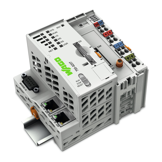
WAGO-I/O-SYSTEM 750 Device Description 750-8207 PFC200 CS 2ETH RS 3G View Figure 1: View of device Table 4: Legend for Figure “View” Item Description See section Marking Options (Mini-WSB) “Indicating elements” > LED Indicators – Power Supply “Indicating element power supply”... - Page 28 Device Description WAGO-I/O-SYSTEM 750 750-8207 PFC200 CS 2ETH RS 3G “Operating elements” > Mode selector switch “Mode selector switch” “Connections” > “Network ETHERNET Connections connections ETHERNET – X1, X2” “Mounting” > “Inserting and Safe Locking Feature Removing Device” “Connections” >...
-
Page 29: Labeling
WAGO-I/O-SYSTEM 750 Device Description 750-8207 PFC200 CS 2ETH RS 3G Labeling The front labeling includes: Device designation Name of the display elements, connections and control elements Serial number with hardware and firmware version The side labeling includes: Manufacturer's identification Connector pin assignment... -
Page 30: Connectors
Device Description WAGO-I/O-SYSTEM 750 750-8207 PFC200 CS 2ETH RS 3G Connectors 3.3.1 Data Contacts/Internal Bus Do not place the I/O modules on the gold spring contacts! Do not place the I/O modules on the gold spring contacts in order to avoid soiling... -
Page 31: Power Jumper Contacts/Field Supply
WAGO-I/O-SYSTEM 750 Device Description 750-8207 PFC200 CS 2ETH RS 3G 3.3.2 Power Jumper Contacts/Field Supply Risk of injury due to sharp-edged blade contacts! The blade contacts are sharp-edged. Handle the I/O module carefully to prevent injury. The controller 750-8207is equipped with 3 self-cleaning power contacts for transferring of the field-side power supply to down-circuit I/O modules. -
Page 32: Cage Clamp ® Connectors
Device Description WAGO-I/O-SYSTEM 750 750-8207 PFC200 CS 2ETH RS 3G ® 3.3.3 CAGE CLAMP Connectors ® Figure 5: CAGE CLAMP connections ® Table 6: Legend for figure “CAGE CLAMP connections” Contact Description Description 24 V System power supply voltage +24 V... -
Page 33: Service Interface
750-8207 PFC200 CS 2ETH RS 3G 3.3.4 Service Interface The service interface is located behind the flap. The Service interface is used for communication with WAGO-I/O-CHECK and WAGO-ETHERNET-Settings and for firmware download. Figure 6: Service Interface (Closed and Open Flap) Table 7: Service Interface... -
Page 34: Network Connections - X1, X2
Device Description WAGO-I/O-SYSTEM 750 750-8207 PFC200 CS 2ETH RS 3G 3.3.5 Network Connections – X1, X2 Figure 7: Network Connections – X1, X2 Table 8: Legend for Figure “Network Connections – X1, X2” Contact Signal Description TD + Transmit Data + TD −... -
Page 35: Rs-232/Rs-485 - X3 Communication Connection
WAGO-I/O-SYSTEM 750 Device Description 750-8207 PFC200 CS 2ETH RS 3G Kommuni kati onsansc hlus s 3.3.6 RS-232/RS-485 – X3 Communication Connection Figure 8: RS-232/RS-485 – X3 Communication Connection Table 9: Legend for Figure “RS-232/RS-485 – X3 Communication Connection” RS-232 RS-485... -
Page 36: Operating As An Rs-232 Interface
Device Description WAGO-I/O-SYSTEM 750 750-8207 PFC200 CS 2ETH RS 3G 3.3.6.1 Operating as an RS-232 Interface Depending on the device type DTE (e.g., PC) or DCE (e.g., PFC, modem), the RS-232 signals have different data directions. Table 10: Function of RS-232 Signals for DTE/DCE... -
Page 37: Operating As An Rs-485 Interface
WAGO-I/O-SYSTEM 750 Device Description 750-8207 PFC200 CS 2ETH RS 3G 3.3.6.2 Operating as an RS-485 Interface To minimize reflection at the end of the line, the RS-485 line must be terminated at both ends by a cable termination. If required, one pull-up or pull-down resistor may be used. -
Page 38: Mobile Radio Antenna
Device Description WAGO-I/O-SYSTEM 750 750-8207 PFC200 CS 2ETH RS 3G 3.3.7 Mobile Radio Antenna The screw connector (SMA jack) for the mobile radio antenna is located at the front of the housing. Figure 12: Mobile Radio Antenna Connection Manual Draft version 1.2.1 from 2017-09-13, valid from FW Version 02.06.20(09) -
Page 39: Display Elements
WAGO-I/O-SYSTEM 750 Device Description 750-8207 PFC200 CS 2ETH RS 3G Display Elements 3.4.1 Power Supply Indicating Elements Figure 13: Power Supply Indicating Elements Table 11: Legend for Figure “Power Supply Indicating Elements” Description Color Description Green/off Status of system power supply voltage... -
Page 40: Fieldbus/System Indicating Elements
Internal data bus status Orange/Off Red/Green/ Module status Orange/Off Red/Green/ Without function Orange/Off User LED, programmable using function Red/Green/ blocks from the WAGO libraries to control the Orange/Off LEDs Red/Green/ ▐██ Signal quality (S5) Orange/Off Red/Green/ ██ Signal quality (S4) -
Page 41: Memory Card Indicating Elements
WAGO-I/O-SYSTEM 750 Device Description 750-8207 PFC200 CS 2ETH RS 3G 3.4.3 Memory Card Indicating Elements Figure 15: Indicating Elements, Memory Card Slot Table 13: Legend for Figure “Indicating Elements, Memory Card Slot” Description Color Description Yellow/Off Memory card status Manual... -
Page 42: Network Indicating Elements
Device Description WAGO-I/O-SYSTEM 750 750-8207 PFC200 CS 2ETH RS 3G 3.4.4 Network Indicating Elements Figure 16: Indicating Elements, RJ-45 Jacks Table 14: Legend for Figure “Indicating Elements, RJ-45 Jacks” Description Color Description Green/Off ETHERNET connection status Yellow/Off ETHERNET data exchange Manual Draft version 1.2.1 from 2017-09-13, valid from FW Version 02.06.20(09) -
Page 43: Mobile Radio Network Status Indicators
WAGO-I/O-SYSTEM 750 Device Description 750-8207 PFC200 CS 2ETH RS 3G 3.4.5 Mobile Radio Network Status Indicators Figure 17: Mobile Radio Network Status Indicators Table 15: Legend for the “Mobile Radio Network Status Indicators” Figure Description Color Description Green/off Mobile radio network status Manual Draft version 1.2.1 from 2017-09-13, valid from FW Version 02.06.20(09) -
Page 44: Operating Elements
Device Description WAGO-I/O-SYSTEM 750 750-8207 PFC200 CS 2ETH RS 3G Operating Elements 3.5.1 Operating Mode Switch Figure 18: Mode Selector Switch The function of the mode selector switch depends on the activated runtime system (CODESYS 2 or e!RUNTIME). 3.5.1.1 CODESYS 2 Runtime System </dg_... -
Page 45: Reset Button
WAGO-I/O-SYSTEM 750 Device Description 750-8207 PFC200 CS 2ETH RS 3G 3.5.2 Reset Button Figure 19: Reset Button The Reset button is installed behind drilling to prevent operating errors. It is a shortstroke button with a low actuating force of 1.1 N … 2.1 N (110 gf … 210 gf). -
Page 46: Slot For Memory Card
</dg_ Only use recommended memory cards! Use only the SD memory card available from WAGO (item No. 758-879/000- 001) as it is suitable for industrial applications subjected to environmental extremes and was developed for use in the controller. Compatibility with other commercially available storage media cannot be guaranteed. -
Page 47: Sim Card Slot
WAGO-I/O-SYSTEM 750 Device Description 750-8207 PFC200 CS 2ETH RS 3G SIM Card Slot Figure 21: SIM Card Slot Table 18: Legend for Figure “SIM Card Slot” Positio Description Release button for SIM card slot SIM card holder SIM card slot The SIM card slot is located on the front of the housing. -
Page 48: Schematic Diagram
Device Description WAGO-I/O-SYSTEM 750 750-8207 PFC200 CS 2ETH RS 3G Schematic Diagram Figure 22: Schematic diagram Manual Draft version 1.2.1 from 2017-09-13, valid from FW Version 02.06.20(09) -
Page 49: Technical Data
WAGO-I/O-SYSTEM 750 Device Description 750-8207 PFC200 CS 2ETH RS 3G Technical Data 3.9.1 Device Data Table 19: Technical Data − Device Data Width 103 mm Height (from upper edge of DIN 35 rail) 65 mm Length 100 mm Weight 288 g </dg_... -
Page 50: Clock
Device Description WAGO-I/O-SYSTEM 750 750-8207 PFC200 CS 2ETH RS 3G 3.9.4 Clock Table 22: Technical Data – Clock Drift - system clock (25 °C) 20 ppm Drift - RTC (25 °C) 3 ppm Buffer time RTC (25 °C) 30 days 3.9.5... -
Page 51: Ethernet
WAGO-I/O-SYSTEM 750 Device Description 750-8207 PFC200 CS 2ETH RS 3G 3.9.7 ETHERNET Table 25: Technical Data – ETHERNET ETHERNET 2 x RJ-45 (switched or separated mode) Transmission medium Twisted Pair S-UTP, 100 Ω, Cat 5, 100 m maximum cable length Baud rate 10/100 Mbit/s;... -
Page 52: Climatic Environmental Conditions
Device Description WAGO-I/O-SYSTEM 750 750-8207 PFC200 CS 2ETH RS 3G Table 29: Technical Data – Power Jumper Contacts Power jumper contacts Spring contact, self-cleaning Table 30: Technical Data – Data Contacts Data contacts Slide contact, hard gold plated, self- cleaning 3.9.11... -
Page 53: Approvals
20 cm entre le radiateur et le corps humain. 3.11 Standards and Guidelines The “PFC200 CS 2ETH RS 3G” controller (750-8207) fulfills the following EMC standards: EMC CE-Immunity to interference EN 61000-6-2 Manual... - Page 54 Device Description WAGO-I/O-SYSTEM 750 750-8207 PFC200 CS 2ETH RS 3G EMC CE-Emission of interference EN 61000-6-3 Manual Draft version 1.2.1 from 2017-09-13, valid from FW Version 02.06.20(09)
-
Page 55: Function Description
WAGO-I/O-SYSTEM 750 Function Description 750-8207 PFC200 CS 2ETH RS 3G Function Description </dg_ Network 4.1.1 Interface Configuration The ETHERNET X1 and X2 interfaces of the controller are connected with an internal 3-port switch, in which the third port is connected to the CPU. -
Page 56: Network Security
Function Description WAGO-I/O-SYSTEM 750 750-8207 PFC200 CS 2ETH RS 3G 4.1.2 Network Security 4.1.2.1 Users and Passwords Several groups of users are provided in the controller which can be used for various services. Default passwords are set for all users. We strongly recommend changing these... -
Page 57: Wbm User Group
WAGO-I/O-SYSTEM 750 Function Description 750-8207 PFC200 CS 2ETH RS 3G 4.1.2.1.2 WBM User Group WBM has its own user administration system. The users in this system are isolated from the other user groups in the system for security reasons. Detailed information about this is given in the Section “WBM User Administration”. -
Page 58: Web Protocols For Wbm Access
Function Description WAGO-I/O-SYSTEM 750 750-8207 PFC200 CS 2ETH RS 3G 4.1.2.2 Web Protocols for WBM Access The HTTP and HTTPS web protocols can be used to access the WBM pages for the controller. HTTPS is preferred because it uses the SSL/TLS protocol. The... - Page 59 WAGO-I/O-SYSTEM 750 Function Description 750-8207 PFC200 CS 2ETH RS 3G BSI Guidelines on Migration to TLS 1.2 The German Federal Office for Information Security guidelines on migration to TLS 1.2 contain “compatibility matrices” that show what software is comparable with TLS 1.2.
-
Page 60: Network Configuration
Function Description WAGO-I/O-SYSTEM 750 750-8207 PFC200 CS 2ETH RS 3G </dg_ 4.1.3 Network Configuration 4.1.3.1 Host Name/Domain Name Without a host name configuration, the controller is assigned a default name which includes the last three values of the controller's MAC address, e.g., “PFCx00-A1A2A3.”... - Page 61 WAGO-I/O-SYSTEM 750 Function Description 750-8207 PFC200 CS 2ETH RS 3G There are two possibilities here: Default Route If the “default” value is entered in the Destination Address field, a default route is defined. The Destination Mask field must then have the value “0.0.0.0.”...
-
Page 62: Network Services
Function Description WAGO-I/O-SYSTEM 750 750-8207 PFC200 CS 2ETH RS 3G 4.1.4 Network Services 4.1.4.1 DHCP Client The controller can get network parameters from an external DHCP master via the DHCP Client service. The following parameters can be obtained: IP address... -
Page 63: Table 34: List Of Parameters Transmitted Via Dhcp
WAGO-I/O-SYSTEM 750 Function Description 750-8207 PFC200 CS 2ETH RS 3G The settings are made, for example, in the WBM via the “DHCP Configuration” page. The DHCP server also passes other parameters in addition to the IP address. The following table shows the complete list. -
Page 64: Dns Server
Function Description WAGO-I/O-SYSTEM 750 750-8207 PFC200 CS 2ETH RS 3G server must be manually configured. For the controller, the DHCP server service is handled by the program "dnsmasq". ® From a Linux command line, an editor must be used to change the file “/etc/dnsmasq.d/dnsmasq_default.conf”... -
Page 65: Memory Card Function
Memory Card Function </dg_ Only use recommended memory cards! Use only the SD memory card available from WAGO (item No. 758-879/000- 001) as it is suitable for industrial applications subjected to environmental extremes and was developed for use in the controller. - Page 66 Function Description WAGO-I/O-SYSTEM 750 750-8207 PFC200 CS 2ETH RS 3G Memory card access from CODESYS only possible with FAT16, FAT32 or NTFS! If the CODESYS user “admin” (see the section “Network” > “Network Security” > “Users and Passwords” > “Services and Users“) is supposed to be able to access files created on the memory card, the memory card must be formatted with FAT16, FAT32 or NTFS.
-
Page 67: Data Backup
WAGO-I/O-SYSTEM 750 Function Description 750-8207 PFC200 CS 2ETH RS 3G 4.2.2 Data Backup The controller has a backup function and a restore function. The necessary settings can be made and the functions can be executed via the WBM pages or via the CBM “Backup” and “Restore” menus. -
Page 68: Restore Function
Function Description WAGO-I/O-SYSTEM 750 750-8207 PFC200 CS 2ETH RS 3G The controller has an automatic update function. If this function is activated on a memory card before the data backup and a controller is booted from this memory card, this data is restored automatically on the internal memory of the controller. - Page 69 WAGO-I/O-SYSTEM 750 Function Description 750-8207 PFC200 CS 2ETH RS 3G File size must not exceed the size of the internal drive! Note that the amount of data in the media/sd/copy/ directory must not exceed the total size of the internal drive.
-
Page 70: Inserting A Memory Card During Operation
Function Description WAGO-I/O-SYSTEM 750 750-8207 PFC200 CS 2ETH RS 3G 4.2.3 Inserting a Memory Card during Operation The fieldbus nodes and the PLC program are running. Insert a memory card during ongoing operation. During normal operation, the memory card is incorporated into the file system of the controller as a drive. -
Page 71: Setting The Home Directory For The Runtime System
WAGO-I/O-SYSTEM 750 Function Description 750-8207 PFC200 CS 2ETH RS 3G 4.2.5 Setting the Home Directory for the Runtime System The home directory for the runtime system is located in the controller's internal memory by default. An existing boot project may be saved in the home directory. -
Page 72: Mounting
Mounting WAGO-I/O-SYSTEM 750 750-8207 PFC200 CS 2ETH RS 3G Mounting Installation Position Along with horizontal and vertical installation, all other installation positions are allowed. Use an end stop in the case of vertical mounting! In the case of vertical assembly, an end stop has to be mounted as an additional safeguard against slipping. - Page 73 WAGO-I/O-SYSTEM 750 Mounting 750-8207 PFC200 CS 2ETH RS 3G Increase the total length using a coupler module for internal data bus extension! You can increase the total length of a fieldbus node by using a 750-628 I/O Module (coupler module for internal data bus extension). For such a configuration, attach a 750-627 I/O Module (end module for internal data bus extension) after the last I/O module of a module assembly.
-
Page 74: Mounting Onto Carrier Rail
WAGO Kontakttechnik GmbH & Co. KG supplies standardized carrier rails that are optimal for use with the I/O system. If other carrier rails are used, then a technical inspection and approval of the rail by WAGO Kontakttechnik GmbH & Co. KG should take place. -
Page 75: Wago Din Rails
WAGO-I/O-SYSTEM 750 Mounting 750-8207 PFC200 CS 2ETH RS 3G 5.3.2 WAGO DIN Rails WAGO carrier rails meet the electrical and mechanical requirements shown in the table below. Table 35: WAGO DIN Rails Item No. Description 210-112 35 × 7.5; 1 mm; steel; bluish, tinned, chromed; slotted 210-113 35 ×... -
Page 76: Mounting Sequence
Don't forget the bus end module! Always plug a bus end module (750-600) onto the end of the fieldbus node! You must always use a bus end module at all fieldbus nodes with WAGO-I/O- SYSTEM 750 fieldbus couplers/controllers to guarantee proper data transfer. -
Page 77: Inserting Devices
WAGO-I/O-SYSTEM 750 Mounting 750-8207 PFC200 CS 2ETH RS 3G Inserting Devices Perform work on devices only if they are de-energized! Working on energized devices can damage them. Therefore, turn off the power supply before working on the devices. 5.6.1 Inserting the Controller... -
Page 78: Inserting The I/O Module
Mounting WAGO-I/O-SYSTEM 750 750-8207 PFC200 CS 2ETH RS 3G 5.6.2 Inserting the I/O Module Position the I/O module so that the tongue and groove joints to the fieldbus coupler/controller or to the previous or possibly subsequent I/O module are engaged. -
Page 79: Connect Devices
Do not connect more than one conductor at one single connection! If more than one conductor must be routed to one connection, these must be connected in an up-circuit wiring assembly, for example using WAGO feed- through terminals. ®... -
Page 80: Power Supply Concept
Connect Devices WAGO-I/O-SYSTEM 750 750-8207 PFC200 CS 2ETH RS 3G Power Supply Concept 6.2.1 Fuse Protection of the Electronic Circuit Power Supply Only implement the electronic circuit power supply with a suitable fuse! The electronic power supply of the controller must only be connected via a slow blow 2A fuse, as shown in the following figure. -
Page 81: Supplementary Power Supply Regulations
750-8207 PFC200 CS 2ETH RS 3G 6.2.2 Supplementary Power Supply Regulations The WAGO-I/O-SYSTEM 750 can also be used in shipbuilding or offshore and onshore areas of work (e. g. working platforms, loading plants). This is demonstrated by complying with the standards of influential classification companies such as Germanischer Lloyd and Lloyds Register. -
Page 82: Commissioning
Commissioning WAGO-I/O-SYSTEM 750 750-8207 PFC200 CS 2ETH RS 3G Commissioning Switching On the Controller Before switching on the controller ensure that you • have properly installed the controller (see section “Installation”), • have connected all required data cables (see section “Connections”) to the... -
Page 83: Determining The Ip Address Of The Host Pc
WAGO-I/O-SYSTEM 750 Commissioning 750-8207 PFC200 CS 2ETH RS 3G Determining the IP Address of the Host PC To ensure that the host PC can communicate with the controller via ETHERNET, both devices must be located in the same subnet. ®... -
Page 84: Setting An Ip Address
Adapt IP addressing for your specific system structure to ensure that the PC and the controller can communicate with one another using one of the available configuration tools (WBM, “WAGO Ethernet Settings”, CBM) (see section “Configuration”). Example for incorporating the controller (192.168.2.17) into an existing network: If the IP address of your host PC is 192.168.1.2, for example, then the controller... -
Page 85: Assigning An Ip Address Using Dhcp
WAGO-I/O-SYSTEM 750 Commissioning 750-8207 PFC200 CS 2ETH RS 3G 7.3.1 Assigning an IP Address using DHCP The Controller can obtain dynamic IP addresses from a server (DHCP/BootP). In contrast to fixed IP addresses, dynamically assigned addresses are not stored permanently. Therefore, a BootP or DHCP server must be available each time the controller is restarted. -
Page 86: Changing An Ip Address Using The "Cbm" Configuration Tool Via The Serial Interface
Commissioning WAGO-I/O-SYSTEM 750 750-8207 PFC200 CS 2ETH RS 3G 7.3.2 Changing an IP Address Using the “CBM” Configuration Tool via the Serial Interface You can also assign a new IP address to the ETHERNET interfaces X1 and X2 ® using the “CBM” configuration tool provided on the Linux console. -
Page 87: Figure 32: Cbm - Selecting "Networking
WAGO-I/O-SYSTEM 750 Commissioning 750-8207 PFC200 CS 2ETH RS 3G In the Main menu use the keyboard (arrow keys or numeric keypad) to move to and select Networking and then press [Enter]. Figure 32: CBM – Selecting “Networking” In the Networking menu select TCP/IP and press [Enter]. -
Page 88: Figure 35: Cbm - Selecting The Ip Address
Commissioning WAGO-I/O-SYSTEM 750 750-8207 PFC200 CS 2ETH RS 3G In the menu TCP/IP Configuration select IP Address and press [Enter]. Figure 35: CBM – Selecting the IP Address In the menu Change IP Address enter the new IP address and confirm by clicking [OK]. -
Page 89: Changing An Ip Address Using "Wago Ethernet Settings
To configure the controller use at least Version 6.4.1.1 dated 2015-06-29 of “WAGO Ethernet Settings”! You can use WAGO communication cables or WAGO radio adapters or even the IP network for data communication. Switch off the power supply to the controller. -
Page 90: Figure 38: "Wago Ethernet Settings" - "Network" Tab
“WAGO Ethernet Settings” will restart your controller. This action may require about 30 seconds.) You can now close “WAGO Ethernet Settings”, or make other changes directly in the Web-based Management system as required. To do this, click on [WBM] at the right in the window. -
Page 91: Temporarily Setting A Fixed Ip Address
WAGO-I/O-SYSTEM 750 Commissioning 750-8207 PFC200 CS 2ETH RS 3G </dg_ 7.3.4 Temporarily Setting a Fixed IP Address This procedure temporarily sets the IP address for the X1 interface to the fixed address “192.168.1.17”. When the switch is enabled, the fixed address is also used for interface X2. -
Page 92: Testing The Network Connection
Commissioning WAGO-I/O-SYSTEM 750 750-8207 PFC200 CS 2ETH RS 3G Testing the Network Connection Carry out a ping network function to check whether you can reach the controller at the IP address you have assigned in the network. Open the MS DOS prompt window. -
Page 93: Changing Standard Passwords
WAGO-I/O-SYSTEM 750 Commissioning 750-8207 PFC200 CS 2ETH RS 3G Changing Standard Passwords Change passwords The standard passwords are documented in these instructions and therefore do not offer adequate protection! Change the passwords to meet your particular needs! To increase security all passwords should contain a combination of lower case letters (a …... -
Page 94: Shutdown/Restart
Commissioning WAGO-I/O-SYSTEM 750 750-8207 PFC200 CS 2ETH RS 3G </dg_ Shutdown/Restart Switch off the power supply to shut down the controller. To perform a controller restart, press the Reset button as described in the Section “Triggering Reset Functions” > “Software Reset (Restart).”... -
Page 95: Initiating Reset Functions
On a cold start reset the CODESYS 2 application is reset and the memory containing the retain variables is cleared. This corresponds to the WAGO I/O PRO IDE “Reset (Cold)” command. </dg_ To perform a cold start reset, set the mode selector switch to “Reset” and hold it there for more than seven seconds. -
Page 96: Software Reset
Commissioning WAGO-I/O-SYSTEM 750 750-8207 PFC200 CS 2ETH RS 3G All e!RUNTIME applications are reset with a cold start reset. All global data and the retain variables are set to their initialization values. This corresponds to the e!COCKPIT IDE “Reset Cold” command. -
Page 97: Configuration
Access via the CODESYS PLC program using the WagoConfigToolLIB.lib library (“Appendix” > “WagoConfigToolLIB.lib”) • Access via the PC using “WAGO Ethernet Settings” (“Configuration Using ‘WAGO Ethernet Settings’”). The CBM is basically for the initial configuration and startup of the controller. -
Page 98: Configuration Via Web-Based-Management (Wbm)
Commissioning WAGO-I/O-SYSTEM 750 750-8207 PFC200 CS 2ETH RS 3G 7.8.1 Configuration via Web-Based-Management (WBM) The HTML pages (from here on referred to as “pages”) of the Web-Based Management are used to configure the controller. Proceed as follows to access the WBM using an Internet browser: Connect the controller to the ETHERNET network via the ETHERNET interface X1. -
Page 99: Wbm User Administration
WAGO-I/O-SYSTEM 750 Commissioning 750-8207 PFC200 CS 2ETH RS 3G Some pages of the WBM are accessible only for certain users. They are only displayed if you have logged into the WBM. You can access the login form via the “Login” link. Pages which cannot be accessed with your current user name are already grayed out in the navigation. -
Page 100: Figure 41: Password Reminder
100 Commissioning WAGO-I/O-SYSTEM 750 750-8207 PFC200 CS 2ETH RS 3G Figure 41: Password Reminder Table 39: User Settings in the Default State Users Password user user admin wago Observe access rights Users in WBM are authorized exclusively for access to websites. User administration for controller applications is configured separately. - Page 101 WAGO-I/O-SYSTEM 750 Commissioning 101 750-8207 PFC200 CS 2ETH RS 3G Table 40: Access Rights for WBM Pages Navigation WBM page User – Reboot Reboot Controller admin Package Server – Firmware Backup Firmware Backup admin – Firmware Restore Firmware Restore admin –...
-
Page 102: General Information About The Page
102 Commissioning WAGO-I/O-SYSTEM 750 750-8207 PFC200 CS 2ETH RS 3G 7.8.1.2 General Information about the Page Figure 42: WBM Browser Window (Example) The device name is displayed in the header of the browser window. When the user has logged out, a [Login] button is displayed on the right in the header line, when logged in a [Logout] button is displayed. - Page 103 WAGO-I/O-SYSTEM 750 Commissioning 103 750-8207 PFC200 CS 2ETH RS 3G • WBM status: This indicates whether the WBM is currently communicating with the device in the background. In other words, one or more requests have been sent and the browser is waiting for a response. Movement is then visible in the graphic.
- Page 104 104 Commissioning WAGO-I/O-SYSTEM 750 750-8207 PFC200 CS 2ETH RS 3G Do not power cycle the controller after changing any parameters! Some parameter changes require a controller restart for the changes to apply. Saving changes takes time. Do not power cycle the controller to perform a restart, i.e., changes may be lost by shutting down the controller too soon.
-
Page 105: Status Information" Page
WAGO-I/O-SYSTEM 750 Commissioning 105 750-8207 PFC200 CS 2ETH RS 3G 7.8.1.3 “Status Information” Page The following tables explain the parameters listed on this page: 7.8.1.3.1 “Controller Details” Group This group displays the properties of the controller. Table 41: WBM “Status Information” Page – “Controller Details” Group... -
Page 106: General Plc Runtime Configuration" Page
106 Commissioning WAGO-I/O-SYSTEM 750 750-8207 PFC200 CS 2ETH RS 3G 7.8.1.4 “General PLC Runtime Configuration” Page The settings for the boot project created with the programming software are given on the “General PLC Runtime Configuration” page. 7.8.1.4.1 “General PLC Runtime Configuration” Group Table 43: WBM “General PLC Runtime Configuration”... - Page 107 WAGO-I/O-SYSTEM 750 Commissioning 107 750-8207 PFC200 CS 2ETH RS 3G The home directory change only takes effect after restarting the controller. For this purpose, use the WBM reboot function. Do not shut down the controller too early! Manual Draft version 1.2.1 from 2017-09-13, valid from FW Version 02.06.20(09)
-
Page 108: Plc Runtime Information" Page
108 Commissioning WAGO-I/O-SYSTEM 750 750-8207 PFC200 CS 2ETH RS 3G 7.8.1.5 “PLC Runtime Information” Page All information about the enabled runtime system and PLC program created in the programming software is provided on the “PLC Runtime Information” page. 7.8.1.5.1 “PLC Runtime” Group Table 44: WBM “PLC Runtime Information”... -
Page 109: Task N" Group(S)
WAGO-I/O-SYSTEM 750 Commissioning 109 750-8207 PFC200 CS 2ETH RS 3G 7.8.1.5.3 “Task n” Group(s) This group is only visible if CODESYS 2 is enabled as the runtime system. One dedicated group is displayed for each task when the PLC program is executed. -
Page 110: Plc Webvisu" Page
110 Commissioning WAGO-I/O-SYSTEM 750 750-8207 PFC200 CS 2ETH RS 3G 7.8.1.6 “PLC WebVisu” Page The settings for the web visualization created in the runtime system are shown on the “PLC WebVisu” page. 7.8.1.6.1 “Web Server Configuration” Group Table 47: WBM “PLC WebVisu” Page – “Web Server Configuration” Group... -
Page 111: Configuration Of Host And Domain Name" Page
WAGO-I/O-SYSTEM 750 Commissioning 111 750-8207 PFC200 CS 2ETH RS 3G 7.8.1.7 “Configuration of Host and Domain Name” Page The settings for the general TCP/IP parameters are found on the “Configuration of Host and Domain Name” page. 7.8.1.7.1 “HostName” Group Table 48: WBM “Configuration of Host and Domain Name” Page – “Hostname” Group... -
Page 112: Tcp/Ip Configuration" Page
112 Commissioning WAGO-I/O-SYSTEM 750 750-8207 PFC200 CS 2ETH RS 3G </dg_ 7.8.1.8 “TCP/IP Configuration” Page The TCP/IP settings for the ETHERNET interfaces are shown on the “TCP/IP configuration” page. 7.8.1.8.1 “IP Configuration (Xn)” Group(s) If the switch is enabled, one group (“IP Configuration”) is shown for both connections. -
Page 113: Default Gateway N" Groups
WAGO-I/O-SYSTEM 750 Commissioning 113 750-8207 PFC200 CS 2ETH RS 3G 7.8.1.8.2 “Default Gateway n” Groups You can configure two default gateways. The controller transmits all network data not going to a station on the local network to a default gateway. First the gateway with the lowest metric is addressed. -
Page 114: Dns Server" Group
114 Commissioning WAGO-I/O-SYSTEM 750 750-8207 PFC200 CS 2ETH RS 3G 7.8.1.8.3 “DNS Server” Group Table 52: WBM “TCP/IP Configuration” Page – “DNS Server” Group Parameters Explanation The addresses of the defined DNS servers are Configured: None/ displayed. If no server has been defined, DNS Server n “Configured: None”... -
Page 115: Ethernet Configuration" Page
WAGO-I/O-SYSTEM 750 Commissioning 115 750-8207 PFC200 CS 2ETH RS 3G 7.8.1.9 “Ethernet Configuration” Page The settings for Ethernet TCP/IP are located on the “Ethernet Configuration” page. 7.8.1.9.1 “Switch Configuration” Group Table 53: WBM “Ethernet Configuration” Page – “Switch Configuration” Group... -
Page 116: Table 54: Wbm "Ethernet Configuration" Page - "Interface Xn" Groups
116 Commissioning WAGO-I/O-SYSTEM 750 750-8207 PFC200 CS 2ETH RS 3G Table 54: WBM “Ethernet Configuration” Page – “Interface Xn” Groups Parameter Explanation Enabled You can enable or disable the interface. When Autonegotiation is enabled, the connection Autonegotiation on modalities are negotiated automatically with the peer devices. -
Page 117: General Firewall Configuration" Page
WAGO-I/O-SYSTEM 750 Commissioning 117 750-8207 PFC200 CS 2ETH RS 3G 7.8.1.10 “General Firewall Configuration” Page 7.8.1.10.1 “Global Firewall Parameters” Group Table 55: WBM “General Firewall Configuration” Page – “Global Firewall Parameters” Group Parameters Explanation Enables/disables the complete functionality of the firewall. -
Page 118: Firewall Parameters Interface Xxx" Group
118 Commissioning WAGO-I/O-SYSTEM 750 750-8207 PFC200 CS 2ETH RS 3G 7.8.1.10.2 “Firewall Parameters Interface xxx” Group These settings in this group refer to the configuration of the firewall at IP level. Table 56: WBM “General Firewall Configuration” Page – “Firewall Parameter Interface Xn” Group... -
Page 119: Configuration Of Mac Address Filter" Page
WAGO-I/O-SYSTEM 750 Commissioning 119 750-8207 PFC200 CS 2ETH RS 3G </dg_ 7.8.1.11 “Configuration of MAC Address Filter” Page You set the firewall configuration at ETHERNET level on this page. The “MAC Address Filter Whitelist” contains a default entry with the following... -
Page 120: Mac Address Filter State Xn" Group
120 Commissioning WAGO-I/O-SYSTEM 750 750-8207 PFC200 CS 2ETH RS 3G 7.8.1.11.2 “MAC Address Filter State Xn” Group Table 58: WBM “Configuration of MAC Address Filter” Page – “MAC Address Filter State Xn” Group Parameters Explanation Enable or disable here the MAC address filter for the Filter enabled specific interface. -
Page 121: Configuration Of User Filter" Page
WAGO-I/O-SYSTEM 750 Commissioning 121 750-8207 PFC200 CS 2ETH RS 3G 7.8.1.12 “Configuration of User Filter” Page 7.8.1.12.1 “User Filter” Group Table 60: WBM “Configuration of User Filter” Page – “User Filter” Group Parameters Explanation Count The number of configured user filters is displayed. -
Page 122: Add New User Filter" Group
122 Commissioning WAGO-I/O-SYSTEM 750 750-8207 PFC200 CS 2ETH RS 3G 7.8.1.12.3 “Add New User Filter” Group You can enter 10 filters. You only have to enter values in the fields that are to be set for the filter. At least one value must be entered, all other fields can remain empty. -
Page 123: Configuration Of Time And Date" Page
WAGO-I/O-SYSTEM 750 Commissioning 123 750-8207 PFC200 CS 2ETH RS 3G 7.8.1.13 “Configuration of Time and Date” Page The settings for date and time are shown on the “Configuration of Time and Date” page. 7.8.1.13.1 “Date on Device” Group Table 63: WBM “Configuration of Time and Date” Page – “Date on Device” Group... -
Page 124: Time Zone" Group
124 Commissioning WAGO-I/O-SYSTEM 750 750-8207 PFC200 CS 2ETH RS 3G 7.8.1.13.3 “Time Zone” Group You can specify the appropriate time zone for your location in this group. The total number of possible time zones is over 500. A complete listing would exceed the scope of this documentation. -
Page 125: Tz String" Group
WAGO-I/O-SYSTEM 750 Commissioning 125 750-8207 PFC200 CS 2ETH RS 3G 7.8.1.13.4 “TZ String” Group In this group you can enter a time zone that is not contained in the “Time Zone” selection. If the controller can associate the TZ string entered with a known time zone that had been missing from the “Time Zone”... -
Page 126: Change Password For Selected User" Group
126 Commissioning WAGO-I/O-SYSTEM 750 750-8207 PFC200 CS 2ETH RS 3G </dg_ 7.8.1.14 “Configuration of the Users for the Web-based Management” Page The settings for user administration are shown on this page. 7.8.1.14.1 “Change Password for Selected User” Group Change passwords Default passwords are documented in these instructions and therefore do not offer adequate protection! Change the passwords to meet your particular needs. -
Page 127: Create Bootable Image" Page
WAGO-I/O-SYSTEM 750 Commissioning 127 750-8207 PFC200 CS 2ETH RS 3G </dg_ 7.8.1.15 “Create Bootable Image” Page You can create a bootable image on the “Create Bootable Image” page. 7.8.1.15.1 "Create Bootable Image from Active Partition (<Active Partition>" Group The active partition that boot-up was performed from is displayed in brackets in the heading. - Page 128 128 Commissioning WAGO-I/O-SYSTEM 750 750-8207 PFC200 CS 2ETH RS 3G Remove the memory card write protection! Because write access to the memory card is possible during the boot process, the memory card cannot be write protected when creating the image and during operation.
-
Page 129: Configuration Of Serial Interface Rs232" Page
WAGO-I/O-SYSTEM 750 Commissioning 129 750-8207 PFC200 CS 2ETH RS 3G </dg_ 7.8.1.16 “Configuration of Serial Interface RS232” Page The settings for the serial interface are shown on the “Configuration of Serial Interface RS232” page. 7.8.1.16.1 “Serial Interface Assigned to” Group The application that the serial interface is currently assigned to is displayed. -
Page 130: Configuration Of Service Interface" Page
130 Commissioning WAGO-I/O-SYSTEM 750 750-8207 PFC200 CS 2ETH RS 3G 7.8.1.17 “Configuration of Service Interface” Page The settings for the service interface are shown on the “Configuration of the Service Interface” page. 7.8.1.17.1 “Service Interface assigned to” Group The application that the service interface is currently assigned to is displayed. -
Page 131: Reboot Controller" Page
WAGO-I/O-SYSTEM 750 Commissioning 131 750-8207 PFC200 CS 2ETH RS 3G </dg_ 7.8.1.18 “Reboot Controller” Page The settings for the system reboot are shown on the “Reboot Controller” page. 7.8.1.18.1 “Reboot Controller” Group Click the [Reboot] button to reboot the system. -
Page 132: Firmware Backup" Page
132 Commissioning WAGO-I/O-SYSTEM 750 750-8207 PFC200 CS 2ETH RS 3G 7.8.1.19 “Firmware Backup” Page You can find the controller data backup settings on the “Firmware Backup” page. Table 71: “Firmware-Backup” WBM Page Parameters Explanation You can select the data to be backed up here. - Page 133 WAGO-I/O-SYSTEM 750 Commissioning 133 750-8207 PFC200 CS 2ETH RS 3G No backup of the memory card! Backup from the memory card to the internal flash memory is not possible. Account for backup time Generation of backup files can take several minutes. Stop the CODESYS program before you start the backup procedure to help shorten the time required.
-
Page 134: Firmware Restore" Page
134 Commissioning WAGO-I/O-SYSTEM 750 750-8207 PFC200 CS 2ETH RS 3G 7.8.1.20 “Firmware Restore” Page The settings for restoring the controller data are shown on the “Firmware Restore” page. Table 72: “Firmware Restore” WBM Page Parameters Explanation Select the data source for the restore here. - Page 135 WAGO-I/O-SYSTEM 750 Commissioning 135 750-8207 PFC200 CS 2ETH RS 3G Note the firmware version! Restoring the controller operating system (“System” selection) is only permissible and possible if the firmware versions at the backup and restore times are identical. If necessary, skip restoring the controller operating system, or match the firmware version of the controller to the firmware version of the backup time beforehand.
-
Page 136: System Partition" Page
136 Commissioning WAGO-I/O-SYSTEM 750 750-8207 PFC200 CS 2ETH RS 3G </dg_ 7.8.1.21 “System Partition” Page The settings for specifying the partition that the system will be started from are shown on the “System Partition” page. 7.8.1.21.1 “Current Active Partition” Group The partition currently in use is displayed here. -
Page 137: Mass Storage" Page
WAGO-I/O-SYSTEM 750 Commissioning 137 750-8207 PFC200 CS 2ETH RS 3G </dg_ 7.8.1.22 “Mass Storage” Page A group containing information about the storage volume is displayed for each storage volume that is found, along with an additional group for formatting (when this is possible). -
Page 138: Software Uploads" Page
138 Commissioning WAGO-I/O-SYSTEM 750 750-8207 PFC200 CS 2ETH RS 3G </dg_ 7.8.1.23 “Software Uploads” Page The settings for a device update are shown on the “Software Uploads” page. 7.8.1.23.1 “Upload New Software” Group Table 75: WBM “Software Uploads” Page – “Upload New Software” Group... -
Page 139: Configuration Of Network Services" Page
WAGO-I/O-SYSTEM 750 Commissioning 139 750-8207 PFC200 CS 2ETH RS 3G </dg_ 7.8.1.24 “Configuration of Network Services” Page The settings for various services are shown on the “Configuration of Network Services” page. Besides enabling/disabling the individual services, you can limit the services for each particular interface also via the firewall on the “General Firewall... -
Page 140: Https" Group
140 Commissioning WAGO-I/O-SYSTEM 750 750-8207 PFC200 CS 2ETH RS 3G Disconnection abort on disabling If the HTTP service is disabled, the connection to the controller can be closed. Then call up the WBM page again. 7.8.1.24.5 “HTTPS” Group Table 81: WBM “Configuration of Network Services” Page – “HTTPS” Group... -
Page 141: Configuration Of Ntp Client" Page
WAGO-I/O-SYSTEM 750 Commissioning 141 750-8207 PFC200 CS 2ETH RS 3G </dg_ 7.8.1.25 “Configuration of NTP Client” Page The settings for the NTP service are shown on the “Configuration of NTP Client” page. 7.8.1.25.1 “NTP Client Configuration” Group Table 83: WBM “Configuration of NTP Client” Page – “NTP Client Configuration” Group... -
Page 142: Configuration Of Plc Runtime Services" Page
142 Commissioning WAGO-I/O-SYSTEM 750 750-8207 PFC200 CS 2ETH RS 3G 7.8.1.26 “Configuration of PLC Runtime Services” Page The settings for various services of the activated runtime system are shown on the “Configuration of PLC Runtime Services” page. 7.8.1.26.1 “General Configuration” Group Table 84: WBM “Configuration of PLC Runtime Services”... - Page 143 WAGO-I/O-SYSTEM 750 Commissioning 143 750-8207 PFC200 CS 2ETH RS 3G Manual Draft version 1.2.1 from 2017-09-13, valid from FW Version 02.06.20(09)
-
Page 144: Ssh Server Settings" Page
144 Commissioning WAGO-I/O-SYSTEM 750 750-8207 PFC200 CS 2ETH RS 3G 7.8.1.27 “SSH Server Settings” Page The settings for the SSH service are shown on the “SSH Server Settings” page. 7.8.1.27.1 “SSH Server” Group Table 87: WBM “SSH Server Settings” Page – “SSH Server” Group... -
Page 145: Tftp Server" Page
WAGO-I/O-SYSTEM 750 Commissioning 145 750-8207 PFC200 CS 2ETH RS 3G </dg_ 7.8.1.28 “TFTP Server” Page The settings for the TFTP service are shown on the “TFTP Server” page. 7.8.1.28.1 “TFTP Server” Group Table 88: WBM “TFTP Server” Page – “TFTP Server” Group... -
Page 146: Dhcp Configuration" Page
146 Commissioning WAGO-I/O-SYSTEM 750 750-8207 PFC200 CS 2ETH RS 3G 7.8.1.29 “DHCP Configuration” Page The settings for the DHCP service are shown on the “DHCP Configuration” page. 7.8.1.29.1 “DHCP Configuration Xn” Group Table 89: WBM “DHCP Configuration” – “DHCP Configuration Xn” Group... -
Page 147: Configuration Of Dns Service" Page
WAGO-I/O-SYSTEM 750 Commissioning 147 750-8207 PFC200 CS 2ETH RS 3G 7.8.1.30 “Configuration of DNS Service” Page The settings for the DNS service are shown on the “Configuration of DNS Service” page. 7.8.1.30.1 “DNS Service” Group Table 90: WBM “Configuration of DNS Service” Page – “DNS Service” Group... -
Page 148: Modbus Services Configuration" Page
148 Commissioning WAGO-I/O-SYSTEM 750 750-8207 PFC200 CS 2ETH RS 3G 7.8.1.31 “MODBUS Services Configuration” Page The settings for various MODBUS services are shown on the “MODBUS Services Configuration” page. The groups are only visible if the e!RUNTIME system is enabled. Otherwise an information text is displayed. -
Page 149: Configuration Of General Snmp Parameters" Page
WAGO-I/O-SYSTEM 750 Commissioning 149 750-8207 PFC200 CS 2ETH RS 3G 7.8.1.32 “Configuration of General SNMP Parameters” Page The general settings for SNMP are given on the “Configuration of General SNMP Parameters” page. 7.8.1.32.1 “General SNMP Configuration” Group Table 93: WBM “Configuration of General SNMP Parameters” Page – “General SNMP Configuration”... -
Page 150: Configuration Of Snmp V1/V2C Parameters" Page
150 Commissioning WAGO-I/O-SYSTEM 750 750-8207 PFC200 CS 2ETH RS 3G 7.8.1.33 “Configuration of SNMP v1/v2c Parameters” Page The general settings for SNMP v1/v2c are shown on the “Configuration of SNMP v1/v2c Parameters” page. 7.8.1.33.1 “SNMP v1/v2c Manager Configuration” Group Table 94: WBM “Configuration of SNMP v1/v2c Parameters” Page – “SNMP v1/v2c Manager Configuration”... -
Page 151: Trap Receiver N" Group(S)
WAGO-I/O-SYSTEM 750 Commissioning 151 750-8207 PFC200 CS 2ETH RS 3G 7.8.1.33.3 “Trap Receiver n” Group(s) A dedicated group with the following information is displayed for each trap receiver: Table 96: WBM “Configuration of SNMP v1/v2c Parameters” Page – “Trap Receiver n” Group(s) -
Page 152: Configuration Of Snmp V3 Users" Page
152 Commissioning WAGO-I/O-SYSTEM 750 750-8207 PFC200 CS 2ETH RS 3G </dg_ 7.8.1.34 “Configuration of SNMP v3 Users” Page The general settings for SNMP v3 are shown on the “Configuration of SNMP v3 Users” page. 7.8.1.34.1 “Actually Configured v3 Users” Group(s) Table 98: WBM “Configuration of SNMP v3”... -
Page 153: Add New V3 User" Group
WAGO-I/O-SYSTEM 750 Commissioning 153 750-8207 PFC200 CS 2ETH RS 3G 7.8.1.34.3 “Add New v3 User” Group You can enter 10 users. Table 100: WBM “Configuration of SNMP v3 Users” Page – “Add New v3 User” Group Parameters Explanation Enter the user name here. This name must be unique;... -
Page 154: Diagnostic Information" Page
154 Commissioning WAGO-I/O-SYSTEM 750 750-8207 PFC200 CS 2ETH RS 3G </dg_ 7.8.1.35 “Diagnostic Information” Page The settings for displaying diagnostic messages are shown on the “Diagnostic Information” page. Table 101: WBM “Diagnostic Information” Page Parameter Explanation Read all notifications Activate display of all messages. -
Page 155: Configuration Of Internal 3G Modem" Page
WAGO-I/O-SYSTEM 750 Commissioning 155 750-8207 PFC200 CS 2ETH RS 3G 7.8.1.36 “Configuration of internal 3G Modem” Page The modem settings are available on the “Configuration of internal 3G Modem” page. 7.8.1.36.1 “SIM Authentication” Group Table 102: WBM “Configuration of internal 3G Modem” Page – “SIM Authentication” Group... -
Page 156: Mobile Network Configuration" Group
156 Commissioning WAGO-I/O-SYSTEM 750 750-8207 PFC200 CS 2ETH RS 3G 7.8.1.36.2 “Mobile Network Configuration” Group Table 103: WBM “Configuration of internal 3G Modem” Page – “Mobile Network Configuration” Group Parameters Explanation State The network status is displayed. Signal Quality (%) The current signal quality is displayed. -
Page 157: Provider List" Group
WAGO-I/O-SYSTEM 750 Commissioning 157 750-8207 PFC200 CS 2ETH RS 3G 7.8.1.36.3 “Provider List” Group Table 104: WBM “Configuration of internal 3G Modem” Page – “Provider List” Group Parameters Explanation <Provider> | <Network> All available providers with the respective network, <ID>, <Status>... -
Page 158: Upload And Activate New Modem Software" Group
158 Commissioning WAGO-I/O-SYSTEM 750 750-8207 PFC200 CS 2ETH RS 3G 7.8.1.36.5 “Upload and activate new Modem Software” Group Table 106: WBM “Configuration of internal 3G Modem” Page – “Upload and activate new Modem Software” Group Parameters Explanation Currently used The current modem firmware version is displayed. -
Page 159: Configuration Of Openvpn And Ipsec" Page
WAGO-I/O-SYSTEM 750 Commissioning 159 750-8207 PFC200 CS 2ETH RS 3G 7.8.1.37 “Configuration of OpenVPN and IPsec” Page The general settings for SNMP v1/v2c are shown on the “Configuration of SNMP v1/v2c Parameters” page. 7.8.1.37.1 “OpenVPN” Group Table 107: WBM “Configuration of OpenVPN and IPsec” Page – “OpenVPN” Group... -
Page 160: Certificate Upload" Group
160 Commissioning WAGO-I/O-SYSTEM 750 750-8207 PFC200 CS 2ETH RS 3G To transfer the selected file from the controller to the PC, click [Start Download] button. The changes only take effect after restarting the controller. For this purpose, use the WBM reboot function. Do not shut down the controller too early! 7.8.1.37.3 “Certificate Upload”... -
Page 161: Security Settings" Page
WAGO-I/O-SYSTEM 750 Commissioning 161 750-8207 PFC200 CS 2ETH RS 3G 7.8.1.38 “Security Settings” Page The network security settings are found on the “Security Settings” page. 7.8.1.38.1 “TLS Configuration” Group Table 112: “Security Settings” WBM Page – “TLS Configuration” Group Parameters... -
Page 162: Open Source Licenses" Page
162 Commissioning WAGO-I/O-SYSTEM 750 750-8207 PFC200 CS 2ETH RS 3G 7.8.2 “Open Source Licenses” Page The licence conditions for the open source software used for the controller are listed in alphabetical order on the “Open Source Licenses” page. Manual Draft version 1.2.1 from 2017-09-13, valid from FW Version 02.06.20(09) -
Page 163: Wago Licenses" Page
Commissioning 163 750-8207 PFC200 CS 2ETH RS 3G 7.8.3 “WAGO Licenses” Page The licence conditions for the WAGO software used in the controller are listed on the “WAGO Licenses” page. Manual Draft version 1.2.1 from 2017-09-13, valid from FW Version 02.06.20(09) -
Page 164: Configuration Using A Terminal Program (Cbm)
164 Commissioning WAGO-I/O-SYSTEM 750 750-8207 PFC200 CS 2ETH RS 3G 7.8.4 Configuration using a Terminal Program (CBM) You can use the Console-Based Management Tool (CBM) to configure the controller via the ETHERNET interface and SSH, as well as the RS-232 interface ®... - Page 165 WAGO-I/O-SYSTEM 750 Commissioning 165 750-8207 PFC200 CS 2ETH RS 3G Table 113: CBM Menu Structure Menu Hierarchy 1. Host-/Domain Name 2. TCP/IP 0. Back to Networking Menu 1. IP Address 2. Default Gateway 3. DNS Server 3. Ethernet 0. Back to Networking Menu 1.
- Page 166 166 Commissioning WAGO-I/O-SYSTEM 750 750-8207 PFC200 CS 2ETH RS 3G Table 113: CBM Menu Structure Menu Hierarchy 1. Update Script 10. Ports and Services 0. Back to Main Menu 1. Telnet 2. FTP 3. FTPS 4. HTTP 5. HTTPS 6. NTP 7.
-
Page 167: Information" Menu
WAGO-I/O-SYSTEM 750 Commissioning 167 750-8207 PFC200 CS 2ETH RS 3G 7.8.4.2 “Information” Menu This menu contains other submenus with information on the controller and network. Table 114: “Information” Menu Menu Item Explanation 0. Back to … Back to the higher-level menu 1. -
Page 168: Information" > "Network Details" Submenu
168 Commissioning WAGO-I/O-SYSTEM 750 750-8207 PFC200 CS 2ETH RS 3G 7.8.4.2.2 “Information” > “Network Details” Submenu In this submenu, the network and interface properties of the controller are displayed. If the EHERNET interfaces are operated in “Switched” mode, a common table (“X1/X2”) is displayed for both connections. -
Page 169: Plc Runtime" Menu
WAGO-I/O-SYSTEM 750 Commissioning 169 750-8207 PFC200 CS 2ETH RS 3G 7.8.4.3 “PLC Runtime” Menu This menu contains other submenus with information and settings for the runtime system. Table 117: “PLC Runtime” Menu Menu Item Explanation 0. Back to … Back to the higher-level menu Opens a submenu with information on the runtime 1. -
Page 170: Information" > "Runtime Version" Submenu
170 Commissioning WAGO-I/O-SYSTEM 750 750-8207 PFC200 CS 2ETH RS 3G 7.8.4.3.2 “Information” > “Runtime Version” Submenu In this submenu, the runtime version is displayed. Table 119: “PLC Runtime” > “Information” > “Runtime Version” Submenu Parameters Explanation The version of the currently enabled runtime system Version is shown. -
Page 171: Information" > "Number Of Tasks" Submenu
WAGO-I/O-SYSTEM 750 Commissioning 171 750-8207 PFC200 CS 2ETH RS 3G 7.8.4.3.5 “Information” > “Number of Tasks” Submenu In this submenu, the number of tasks in the PLC program are displayed. The submenu only appears when CODESYS 2 is enabled as the runtime system. -
Page 172: Tasks" > "Task N" Submenu
172 Commissioning WAGO-I/O-SYSTEM 750 750-8207 PFC200 CS 2ETH RS 3G 7.8.4.3.8 “Tasks” > “Task n” Submenu In this submenu, information on the selected task is displayed. The submenu only appears when CODESYS 2 is enabled as the runtime system. Table 125: “PLC Runtime” > “Information” > “Tasks” > “Task n” Submenu... -
Page 173: General Configuration" > "Plc Runtime Version" Submenu
WAGO-I/O-SYSTEM 750 Commissioning 173 750-8207 PFC200 CS 2ETH RS 3G 7.8.4.3.10 “General Configuration” > “PLC Runtime Version” Submenu In this submenu, select which PLC runtime system is enabled. Table 127: “PLC Runtime” > “General Configuration” > “PLC Runtime Version” Submenu... -
Page 174: Plc Runtime" > "Webvisu" Submenu
174 Commissioning WAGO-I/O-SYSTEM 750 750-8207 PFC200 CS 2ETH RS 3G 7.8.4.3.12 “PLC Runtime” > “WebVisu” Submenu This submenu contains information and settings for the Web visualization. Table 129: “PLC Runtime” > “WebVisu” Submenu Menu Item Submenu Item / Explanation 0. Back to …... -
Page 175: Networking" Menu
WAGO-I/O-SYSTEM 750 Commissioning 175 750-8207 PFC200 CS 2ETH RS 3G 7.8.4.4 “Networking” Menu This menu contains other submenus with settings for the network configuration. Table 130: “Networking” Menu Parameters Explanation 0. Back to … Back to the higher-level menu Opens a submenu with setting options for the 1. -
Page 176: Host/Domain Name" > "Hostname" Submenu
176 Commissioning WAGO-I/O-SYSTEM 750 750-8207 PFC200 CS 2ETH RS 3G 7.8.4.4.2 “Host/Domain Name” > “Hostname” Submenu In this submenu, you can set the hostname of the controller. Table 132: “Networking” > “Hostname” Submenu Parameters Explanation Enter here the hostname of the controller to be used... -
Page 177: Tcp/Ip" > "Ip Address" Submenu
WAGO-I/O-SYSTEM 750 Commissioning 177 750-8207 PFC200 CS 2ETH RS 3G 7.8.4.4.5 “TCP/IP” > “IP Address” Submenu This submenu contains other submenus with settings for the ETHERNET interfaces. The submenu only appears if the controller is operated in “Separated” mode. If the controller is operated in “Switched” mode, then the “IP Address” > “X1”... -
Page 178: Tcp/Ip" > "Default Gateway" Submenu
178 Commissioning WAGO-I/O-SYSTEM 750 750-8207 PFC200 CS 2ETH RS 3G 7.8.4.4.7 “TCP/IP” > “Default Gateway” Submenu This submenu contains other submenus with settings for the default gateway. Table 137: “Networking” > “TCP/IP” > “Default Gateway” Submenu Menu Item Explanation 0. Back to …... -
Page 179: Tcp/Ip" > "Dns Server" Submenu
WAGO-I/O-SYSTEM 750 Commissioning 179 750-8207 PFC200 CS 2ETH RS 3G 7.8.4.4.9 “TCP/IP” > “DNS Server” Submenu This submenu contains the settings for the DNS server. Table 139: “Networking” > “TCP/IP” > “DNS Server” Submenu Menu Item Submenu Item / Explanation 0. -
Page 180: Ethernet" > "Switch Configuration" Submenu
180 Commissioning WAGO-I/O-SYSTEM 750 750-8207 PFC200 CS 2ETH RS 3G 7.8.4.4.11 “Ethernet” > “Switch Configuration” Submenu This submenu contains the settings for the Switch configuration. Table 141: “Networking” > “Ethernet” > “Switch Configuration” Submenu Submenu Submenu Item / Explanation 0. Back to …... -
Page 181: Ethernet Ports" > "Interface Xn" Submenu
WAGO-I/O-SYSTEM 750 Commissioning 181 750-8207 PFC200 CS 2ETH RS 3G 7.8.4.4.13 “Ethernet Ports” > “Interface Xn” Submenu This submenu contains the settings for the selected ETHERNET interface. Table 143: “Networking” > “Ethernet” > “Ethernet Ports” > “Interface Xn” Submenu Submenu Submenu Item / Explanation 0. -
Page 182: Firewall" Menu
182 Commissioning WAGO-I/O-SYSTEM 750 750-8207 PFC200 CS 2ETH RS 3G 7.8.4.5 “Firewall” Menu This menu contains other submenus for the firewall functionality settings. Table 144: “Firewall” Menu Menu Item Explanation 0. Back to … Back to the higher-level menu 1. General Configuration Opens a submenu with general firewall settings 2. -
Page 183: Firewall" > "General Configuration" Submenu
WAGO-I/O-SYSTEM 750 Commissioning 183 750-8207 PFC200 CS 2ETH RS 3G 7.8.4.5.1 “Firewall” > “General Configuration” Submenu This submenu contains the general settings for the firewall. Table 145: “Firewall” > “General Configuration” Submenu Menu Item Submenu Item / Explanation 0. Back to …... -
Page 184: General Configuration" > "Interface Xxx" Submenu
184 Commissioning WAGO-I/O-SYSTEM 750 750-8207 PFC200 CS 2ETH RS 3G 7.8.4.5.2 “General Configuration” > “Interface xxx” Submenu This submenu contains the firewall settings on the IP level for the selected interface. Table 146: “Firewall” > “General Configuration” > “Interface xxx” Submenu... - Page 185 WAGO-I/O-SYSTEM 750 Commissioning 185 750-8207 PFC200 CS 2ETH RS 3G Click [<OK>] to apply the entry. Click [<Abort>] to discard the entry. Manual Draft version 1.2.1 from 2017-09-13, valid from FW Version 02.06.20(09)
-
Page 186: Firewall" > "Mac Address Filter" Submenu
186 Commissioning WAGO-I/O-SYSTEM 750 750-8207 PFC200 CS 2ETH RS 3G 7.8.4.5.3 “Firewall” > “MAC Address Filter” Submenu This submenu contains the settings for the MAC address filter. Table 147: “Firewall” > “MAC Address Filter” Submenu Menu Item Submenu Item / Explanation 0. -
Page 187: Mac Address Filter" > "Mac Address Filter Whitelist" Submenu187
WAGO-I/O-SYSTEM 750 Commissioning 187 750-8207 PFC200 CS 2ETH RS 3G 7.8.4.5.4 “MAC Address Filter” > “MAC address filter whitelist” Submenu This submenu displays all available filter entries. Table 148: “Firewall” > “MAC Address Filter” > “MAC address filter whitelist” Submenu... -
Page 188: Firewall" > "User Filter" Submenu
188 Commissioning WAGO-I/O-SYSTEM 750 750-8207 PFC200 CS 2ETH RS 3G 7.8.4.5.6 “Firewall” > “User Filter” Submenu This submenu displays all available filter entries. Table 150: “Firewall” > “User Filter” Submenu Menu Item Explanation 0. Back to … Back to the higher-level menu 1. -
Page 189: User Filter" > "Add New / No (N)" Submenu
WAGO-I/O-SYSTEM 750 Commissioning 189 750-8207 PFC200 CS 2ETH RS 3G 7.8.4.5.7 “User Filter” > “Add New / No (n)” Submenu In this submenu, you can create, change or delete filter entries. Table 151: “Firewall” > “User Filter” > “Add New / No (n)” Submenu... -
Page 190: Clock" Menu
190 Commissioning WAGO-I/O-SYSTEM 750 750-8207 PFC200 CS 2ETH RS 3G 7.8.4.6 “Clock” Menu This menu contains other submenus for the date and time settings. Table 152: “Clock” Menu Menu Item Submenu Item / Explanation 0. Back to … Back to the higher-level menu 1. -
Page 191: Administration" Menu
WAGO-I/O-SYSTEM 750 Commissioning 191 750-8207 PFC200 CS 2ETH RS 3G 7.8.4.7 “Administration” Menu This menu contains settings for controller administration. Table 153: “Administration” Menu Menu Item Submenu Item / Explanation 0. Back to … Back to the higher-level menu Opens a submenu with settings for the user 1. -
Page 192: Administration" > "Create Image" Submenu
192 Commissioning WAGO-I/O-SYSTEM 750 750-8207 PFC200 CS 2ETH RS 3G 7.8.4.7.1 “Administration” > “Create Image” Submenu This submenu contains the selection for creating the image. In addition to the menu item for the enabled storage medium, the current status is displayed. -
Page 193: Package Server" Menu
WAGO-I/O-SYSTEM 750 Commissioning 193 750-8207 PFC200 CS 2ETH RS 3G 7.8.4.8 “Package Server” Menu This menu contains other submenus with functions for firmware backup and restore, as well as information and setting options for the current system partition. Table 156: “Package Server” Menu... -
Page 194: Firmware Backup" > "Auto Update Feature" Submenu
194 Commissioning WAGO-I/O-SYSTEM 750 750-8207 PFC200 CS 2ETH RS 3G 7.8.4.8.2 “Firmware Backup” > “Auto Update Feature” Submenu This submenu contains a setting option for the Auto Update function. The submenu only appears if the data for the firmware backup has been selected. -
Page 195: Package Server" > "Firmware Restore" Submenu
WAGO-I/O-SYSTEM 750 Commissioning 195 750-8207 PFC200 CS 2ETH RS 3G 7.8.4.8.4 “Package Server” > “Firmware Restore” Submenu This submenu contains a selection option for the restore source drive. In addition to the enabled partition, the current status is displayed. Table 160: “Package Server” > “Firmware Restore” Menu... -
Page 196: Package Server" > "System Partition" Submenu
196 Commissioning WAGO-I/O-SYSTEM 750 750-8207 PFC200 CS 2ETH RS 3G 7.8.4.8.6 “Package Server” > “System Partition” Submenu This submenu contains information and setting options for the current system partition. Table 162: “Package Server” > “System Partition” Submenu Menu Item Explanation 0. -
Page 197: Mass Storage" Menu
WAGO-I/O-SYSTEM 750 Commissioning 197 750-8207 PFC200 CS 2ETH RS 3G 7.8.4.9 “Mass Storage” Menu This menu contains information on the internal flash memory and, if inserted, on the external memory card. In addition to the menu item, the status is displayed for the enabled partition. -
Page 198: Software Uploads" Menu
198 Commissioning WAGO-I/O-SYSTEM 750 750-8207 PFC200 CS 2ETH RS 3G 7.8.4.10 “Software Uploads” Menu This menu contains choices and settings for the device update. You can select fieldbus software, program licenses and update scripts, for example, for transfer from a PC to the controller. -
Page 199: Ports And Services" Menu
Opens a submenu with settings for the DHCPD 9. DHCPD service 10. DNS Opens a submenu with settings for the DNS service Opens a submenu with settings for the WAGO-I/O- 11. IOCHECK PORT CHECK port Opens a submenu with settings for the MODBUS 12. Modbus TCP... -
Page 200: Ports And Services" > "Telnet" Submenu
200 Commissioning WAGO-I/O-SYSTEM 750 750-8207 PFC200 CS 2ETH RS 3G 7.8.4.11.1 “Ports and Services” > “Telnet” Submenu This submenu contains the settings for the Telnet service. Table 166: “Ports and Services” > “Telnet” Submenu Menu Item Submenu Item / Explanation 0. -
Page 201: Ports And Services" > "Ftps" Submenu
WAGO-I/O-SYSTEM 750 Commissioning 201 750-8207 PFC200 CS 2ETH RS 3G 7.8.4.11.3 “Ports and Services” > “FTPS” Submenu This submenu contains the settings for the FTPS service. Table 168: “Ports and Services” > “FTPS” Submenu Menu Item Submenu Item / Explanation 0. -
Page 202: Ports And Services" > "Https" Submenu
202 Commissioning WAGO-I/O-SYSTEM 750 750-8207 PFC200 CS 2ETH RS 3G 7.8.4.11.5 “Ports and Services” > “HTTPS” Submenu This submenu contains the settings for the HTTPS service. Table 170: “Ports and Services” > “HTTPS” Submenu Menu Item Submenu Item / Explanation 0. -
Page 203: Ports And Services" > "Ssh" Submenu
WAGO-I/O-SYSTEM 750 Commissioning 203 750-8207 PFC200 CS 2ETH RS 3G 7.8.4.11.7 “Ports and Services” > “SSH” Submenu This submenu contains the settings for the SSH service. Table 172: “Ports and Services” > “SSH” Submenu Menu Item Submenu Item / Explanation 0. -
Page 204: Ports And Services" > "Dhcpd" Submenu
204 Commissioning WAGO-I/O-SYSTEM 750 750-8207 PFC200 CS 2ETH RS 3G 7.8.4.11.9 “Ports and Services” > “DHCPD” Submenu This submenu contains the settings for the DHCPD service. Table 174: “Ports and Services” > “DHCPD” Submenu Menu Item Explanation 0. Back to …... -
Page 205: Ports And Services" > "Dns" Submenu
WAGO-I/O-SYSTEM 750 Commissioning 205 750-8207 PFC200 CS 2ETH RS 3G 7.8.4.11.11 “Ports and Services” > “DNS” Submenu This submenu contains the settings for the DNS service. Table 176: “Ports and Services” > “DNS” Submenu Menu Item Submenu Item / Explanation 0. -
Page 206: Ports And Services" > "Iocheck Port" Submenu
206 Commissioning WAGO-I/O-SYSTEM 750 750-8207 PFC200 CS 2ETH RS 3G 7.8.4.11.12 “Ports and Services” > “IOCHECK PORT” Submenu This submenu contains settings for the WAGO-I/O-CHECK port. Table 177: “Ports and Services” > “IOCHECK PORT” Submenu Menu Item Submenu Item / Explanation 0. -
Page 207: Ports And Services" > "Modbus Udp" Submenu
WAGO-I/O-SYSTEM 750 Commissioning 207 750-8207 PFC200 CS 2ETH RS 3G 7.8.4.11.14 “Ports and Services” > “Modbus UDP” Submenu This submenu contains the settings for the MODBUS UDP service. Table 179: “Ports and Services” > “Modbus UDP” Submenu Menu Item Submenu Item / Explanation 0. -
Page 208: Plc Runtime Services" > "Codesys 2" Submenu
208 Commissioning WAGO-I/O-SYSTEM 750 750-8207 PFC200 CS 2ETH RS 3G 7.8.4.11.16 “PLC Runtime Services” > “CODESYS 2” Submenu This submenu contains the settings for the CODESYS 2 service. Table 181: “Ports and Services” > “PLC Runtime Services” > “CODESYS 2” Submenu... -
Page 209: Plc Runtime Services" > "E!Runtime" Submenu
WAGO-I/O-SYSTEM 750 Commissioning 209 750-8207 PFC200 CS 2ETH RS 3G 7.8.4.11.17 “PLC Runtime Services” > “e!RUNTIME” Submenu This submenu contains the settings for the e!RUNTIME service. Table 182: “Ports and Services” > “PLC Runtime Services” > “e!RUNTIME” Submenu Menu Item Submenu Item / Explanation 0. -
Page 210: Firewall Status" Submenu
210 Commissioning WAGO-I/O-SYSTEM 750 750-8207 PFC200 CS 2ETH RS 3G 7.8.4.11.18 “…” > “Firewall Status” Submenu This submenu contains firewall settings for the selected service. Table 183: “Ports and Services” > “Firewall Status” Submenu Menu Item Submenu Item / Explanation 0. -
Page 211: Snmp" Menu
WAGO-I/O-SYSTEM 750 Commissioning 211 750-8207 PFC200 CS 2ETH RS 3G 7.8.4.12 “SNMP” Menu This menu contains other submenus with the SNMP settings. Table 184: “SNMP” Menu Parameters Explanation 0. Back to … Back to the higher-level menu 1. General SNMP... -
Page 212: Snmp" > "Snmp V1/V2C Manager Configuration" Submenu
212 Commissioning WAGO-I/O-SYSTEM 750 750-8207 PFC200 CS 2ETH RS 3G 7.8.4.12.2 “SNMP” > “SNMP v1/v2c Manager Configuration” Submenu This submenu contains the SNMP v1/v2c Manager settings. Table 186: “SNMP” > “SNMP v1/v2c Manager Configuration” Submenu Parameters Submenu Item / Explanation 0. -
Page 213: Snmp" > "Snmp V3 Configuration" Submenu
WAGO-I/O-SYSTEM 750 Commissioning 213 750-8207 PFC200 CS 2ETH RS 3G 7.8.4.12.4 “SNMP” > “SNMP v3 Configuration” Submenu This submenu contains settings for SNMP v3. Table 188: “SNMP” > “SNMP v3 Configuration” Submenu Parameters Explanation 0. Back to … Back to the higher-level menu Opens a submenu with information on the selected (n). -
Page 214: Snmp" > "(Secure)Snmp Firewalling" Submenu
214 Commissioning WAGO-I/O-SYSTEM 750 750-8207 PFC200 CS 2ETH RS 3G 7.8.4.12.5 “SNMP” > “(Secure)SNMP firewalling” Submenu These submenus contain the SNMP firewall settings. Table 189: “SNMP” > “(Secure )SNMP firewalling” Submenu Menu Item Submenu Item / Explanation 0. Back to …... -
Page 215: Configuration Using "Wago Ethernet Settings
Observe the software version! To configure the controller, use at least Version 6.4.1.1 dated 2015-06-29 or newer of “WAGO ETHERNET Settings”! You must select the correct COM port after starting “WAGO ETHERNET Settings”. Figure 45: “WAGO ETHERNET Settings” – Start Screen For this, click “Settings”... -
Page 216: Figure 46: "Wago Ethernet Settings" - Communication Link
750-8207 PFC200 CS 2ETH RS 3G Figure 46: “WAGO ETHERNET Settings” – Communication Link Once you have configured “WAGO ETHERNET Settings” and have clicked [OK], connection to the controller is established automatically. If “WAGO ETHERNET Settings” has already been started with the correct parameters, you can establish connection to the controller by clicking [Identify]. -
Page 217: Identification Tab
Besides some fixed values — e.g., item No., MAC address and firmware version — the currently used IP address and the configuration method are also shown here. Figure 47: “WAGO ETHERNET Settings” – Identification Tab (Example) Manual Draft version 1.2.1 from 2017-09-13, valid from FW Version 02.06.20(09) -
Page 218: Network Tab
Specify the specific network parameters for static configuration. Restricted setting for default gateways! Only the default gateway 1 can be set via “WAGO Ethernet Settings.” The default gateway 2 can only be set in the WBM! Preferred DNS server, alternative DNS server Enter the IP address (when required) for an accessible DNS server when identifying network names. - Page 219 WAGO-I/O-SYSTEM 750 Commissioning 219 750-8207 PFC200 CS 2ETH RS 3G this name is composed of the string “PFCx00” and the last three bytes of the MAC address. This standard value is also used whenever the chosen name in the “Input”...
-
Page 220: Protocol Tab
220 Commissioning WAGO-I/O-SYSTEM 750 750-8207 PFC200 CS 2ETH RS 3G 7.8.5.3 Protocol Tab Figure 49: “WAGO ETHERNET Settings” – Protocol Tab You can enable or disable the Web server. Manual Draft version 1.2.1 from 2017-09-13, valid from FW Version 02.06.20(09) -
Page 221: Status Tab
750-8207 PFC200 CS 2ETH RS 3G 7.8.5.4 Status Tab Figure 50: “WAGO ETHERNET Settings” – Status Tab General information about the controller status is displayed here. The Bus extension check box has no function for the controller PFCx00, i.e., the bus extension is always active. -
Page 222: Run-Time System Codesys 2.3
750-8207 PFC200 CS 2ETH RS 3G Run-time System CODESYS 2.3 Installing the CODESYS 2.3 Programming System The WAGO target files must also be included for the installation of CODESYS. These contain all device-specific information for the WAGO 750/758 product series. -
Page 223: Figure 51: Target System Settings (1)
WAGO-I/O-SYSTEM 750 Run-time System CODESYS 2.3 223 750-8207 PFC200 CS 2ETH RS 3G Click on [OK]. The “Target system settings” configuration window then opens. Figure 51: Target System Settings (1) To accept the default configuration for the fieldbus controller click [OK]. -
Page 224: Creating The Plc Configuration
224 Run-time System CODESYS 2.3 WAGO-I/O-SYSTEM 750 750-8207 PFC200 CS 2ETH RS 3G In this “New component” window create a new program function block. In the example shown here, the new function block “PLC_PRG” is created in the “ST” programming language. -
Page 225: Figure 55: "Resources" Tab
WAGO-I/O-SYSTEM 750 Run-time System CODESYS 2.3 225 750-8207 PFC200 CS 2ETH RS 3G Figure 55: “Resources” Tab In the left window double-click on “PLC configuration”. The PLC configuration for the controller opens. Manual Draft version 1.2.1 from 2017-09-13, valid from FW Version 02.06.20(09) -
Page 226: Figure 56: Control Configuration - Edit
There are three options for accepting the topology for the I/O modules connected to the fieldbus controller. The simplest way is to scan in the topology using WAGO-I/O-CHECK. To do this, click on the “Start WAGO-I/O-CHECK and scan” button. Figure 57: “Start WAGO-I/O-CHECK and Scan” Button Ensure proper installation of WAGO-I/O-CHECK! This function requires that the latest version of WAGO-I/O-CHECK be installed and the IP address set under “Online >... -
Page 227: Figure 58: Wago-I/O-Check - Starting Screen
Figure 58: WAGO-I/O-CHECK – Starting Screen To connect to the controller and read in the module configuration, click [Identify]. If this action is successful click [Save] and exit WAGO-I/O-CHECK. Manual Draft version 1.2.1 from 2017-09-13, valid from FW Version 02.06.20(09) -
Page 228: Figure 59: I/O Configurator Empty
228 Run-time System CODESYS 2.3 WAGO-I/O-SYSTEM 750 750-8207 PFC200 CS 2ETH RS 3G The detected I/O modules then appear in the configuration window. Passive I/O Modules Remember that passive I/O modules, such as a power supply module (750-602) or end module (750-600) will not be shown in the I/O configurator. -
Page 229: Figure 61: "Module Selection" Window
WAGO-I/O-SYSTEM 750 Run-time System CODESYS 2.3 229 750-8207 PFC200 CS 2ETH RS 3G You can select a module in the new “Module selection” window that then appears. Figure 61: “Module Selection” Window You can change the position of an I/O module by marking it and then using the arrow buttons at the right edge of the window to move it up or down. -
Page 230: Figure 63: Variable Declaration
230 Run-time System CODESYS 2.3 WAGO-I/O-SYSTEM 750 750-8207 PFC200 CS 2ETH RS 3G To close the I/O Configurator, click [OK]. The individual inputs and outputs of the selected I/O module are displayed in the right half of the configuration window. -
Page 231: Editing The Program Function Block
WAGO-I/O-SYSTEM 750 Run-time System CODESYS 2.3 231 750-8207 PFC200 CS 2ETH RS 3G 8.2.4 Editing the Program Function Block To edit the PLC_PRG program function block, go to the “Function block” tab and double-click on the PLC_PRG program module. Figure 65: Program Function Block The following example illustrates the editing of the program function block. -
Page 232: Figure 67: Example Of An Allocation
232 Run-time System CODESYS 2.3 WAGO-I/O-SYSTEM 750 750-8207 PFC200 CS 2ETH RS 3G Repeat Step 2 for the “Input_1” variable. Figure 67: Example of an Allocation To compile, click on Project > Compile all in the menu bar. Manual Draft version 1.2.1 from 2017-09-13, valid from FW Version 02.06.20(09) -
Page 233: Loading And Running The Plc Program In The Fieldbus Controller (Ethernet)
WAGO-I/O-SYSTEM 750 Run-time System CODESYS 2.3 233 750-8207 PFC200 CS 2ETH RS 3G 8.2.5 Loading and Running the PLC Program in the Fieldbus Controller (ETHERNET) Requirement: The simulation is deactivated (Online > Simulation). The PC is linked to the controller via ETHERNET. Refer to Section “Device Description”... -
Page 234: Figure 69: Creating A Communication Link - Step 2
234 Run-time System CODESYS 2.3 WAGO-I/O-SYSTEM 750 750-8207 PFC200 CS 2ETH RS 3G In the “Name” field enter a designation for your fieldbus controller and then click on “Tcp/Ip (Level 2 Route)”. Then click [OK]. Figure 69: Creating a Communication Link – Step 2 In the “Communication Parameters”... -
Page 235: Creating A Boot Project
WAGO-I/O-SYSTEM 750 Run-time System CODESYS 2.3 235 750-8207 PFC200 CS 2ETH RS 3G 8.2.6 Creating a Boot Project Create a boot project to ensure that the PLC program starts automatically again after a fieldbus controller restart. In the menu bar select Online > Create boot project. -
Page 236: Creating Tasks
236 Run-time System CODESYS 2.3 WAGO-I/O-SYSTEM 750 750-8207 PFC200 CS 2ETH RS 3G Enter the character string of the absolute address without empty spaces. The first bit of a word has an address of 0. Creating Tasks Set the time response and the priority of individual tasks in the task configuration. -
Page 237: Figure 72: Changing Task Names 1
WAGO-I/O-SYSTEM 750 Run-time System CODESYS 2.3 237 750-8207 PFC200 CS 2ETH RS 3G To assign a new name to the task (e.g. PLC_Prog), click on “New Task”. Then select the type of task. In this example, this is the “cyclic” type. -
Page 238: Figure 73: Call-Up To Add To The Program Module
238 Run-time System CODESYS 2.3 WAGO-I/O-SYSTEM 750 750-8207 PFC200 CS 2ETH RS 3G Add the program module PLC_PRG that you have just created (see Section “Editing the Program Modules”). To do this, right-clock on the “Clock” symbol and in the contextual menu select “Attach program call-up”. -
Page 239: Cyclic Tasks
WAGO-I/O-SYSTEM 750 Run-time System CODESYS 2.3 239 750-8207 PFC200 CS 2ETH RS 3G 8.4.1 Cyclic Tasks You can assign a priority for each task in order to establish the task processing sequence. Figure 74: Cyclic Task Order of Task Processing The priorities given below do not specifiy the order of task processing. -
Page 240: Freewheeling Tasks
240 Run-time System CODESYS 2.3 WAGO-I/O-SYSTEM 750 750-8207 PFC200 CS 2ETH RS 3G … 31. These tasks all receive the same computing time from the operating system (“Completely Fair Scheduler” procedure). 8.4.2 Freewheeling Tasks So-called freewheeling tasks are not processed in cycles. Their processing depends solely on the current capacity of the system. -
Page 241: Figure 76: Debugging (Case 1)
WAGO-I/O-SYSTEM 750 Run-time System CODESYS 2.3 241 750-8207 PFC200 CS 2ETH RS 3G Figure 76: Debugging (Case 1) Figure 77: Debugging (Case 2) Manual Draft version 1.2.1 from 2017-09-13, valid from FW Version 02.06.20(09) -
Page 242: Figure 78: Debugging (Case 3)
242 Run-time System CODESYS 2.3 WAGO-I/O-SYSTEM 750 750-8207 PFC200 CS 2ETH RS 3G If the mode selector switch and the STOP function of the user interface are used simultaneously, the mode selector switch has priority (case 3 and case 4). -
Page 243: Figure 80: Debugging (Case 5)
WAGO-I/O-SYSTEM 750 Run-time System CODESYS 2.3 243 750-8207 PFC200 CS 2ETH RS 3G As soon as a task is located at a breakpoint, only all other tasks can be controlled with the mode selector switch. Exception: If the mode selector switch is on STOP, the debug task is also no longer processed. -
Page 244: System Events
244 Run-time System CODESYS 2.3 WAGO-I/O-SYSTEM 750 750-8207 PFC200 CS 2ETH RS 3G If a task is at a breakpoint and the connection to the IDE is broken (e.g., by logging out), all breakpoints are deleted. The debug task stays at the current position until the next time the mode selector switch is switched from STOP to RUN. -
Page 245: Figure 83: Codesys - System Events
WAGO-I/O-SYSTEM 750 Run-time System CODESYS 2.3 245 750-8207 PFC200 CS 2ETH RS 3G Figure 83: CODESYS – System Events Do not set debug points in the event handlers! Debug points in event handlers can lead to unforeseeable errors and must... -
Page 246: Table 191: Events
246 Run-time System CODESYS 2.3 WAGO-I/O-SYSTEM 750 750-8207 PFC200 CS 2ETH RS 3G The following events can be activated: Table 191: Events Name Description start The event is called directly after the user program starts. stop The event is called directly after the user program stops. -
Page 247: Creating An Event Handler
WAGO-I/O-SYSTEM 750 Run-time System CODESYS 2.3 247 750-8207 PFC200 CS 2ETH RS 3G 8.5.1 Creating an Event Handler The example here is provided to illustrate how to define and use an event handler. The event handler “excpt_dividebyzero” is used in this example. -
Page 248: Figure 86: Codesys - New Module Has Been Generated
248 Run-time System CODESYS 2.3 WAGO-I/O-SYSTEM 750 750-8207 PFC200 CS 2ETH RS 3G Figure 86: CODESYS – New Module has been Generated Handling for the event that has occurred is now programmed in this new function. In the example here, the event is documented in a global variable. -
Page 249: Process Images
WAGO-I/O-SYSTEM 750 Run-time System CODESYS 2.3 249 750-8207 PFC200 CS 2ETH RS 3G Figure 88: CODESYS – Variable Contents Prior to Division by “0” Figure 89: CODESYS – Variable Contents After Division by “0” and Call-up of the Event Handler... -
Page 250: Figure 90: Process Image
250 Run-time System CODESYS 2.3 WAGO-I/O-SYSTEM 750 750-8207 PFC200 CS 2ETH RS 3G the PFC variables, the bit memory address area and the slaves attached to the fieldbus. Figure 90: Process Image Manual Draft version 1.2.1 from 2017-09-13, valid from FW Version 02.06.20(09) -
Page 251: Process Images For I/O Modules Connected To The Controller
WAGO-I/O-SYSTEM 750 Run-time System CODESYS 2.3 251 750-8207 PFC200 CS 2ETH RS 3G Figure 91: Flag Area 8.6.1 Process Images for I/O Modules Connected to the Controller After starting the fieldbus controller, it automatically detects all connected I/O modules. The analog input and output data is stored first word by word in the process image. -
Page 252: Process Image For Slaves Connected To The Fieldbus
64 ) in the RAM. Byte %QB0 to %QB1999 * The use of up to 250 I/O modules is possible with the WAGO internal data bus extension modules. Manual Draft version 1.2.1 from 2017-09-13, valid from FW Version 02.06.20(09) -
Page 253: Table 193: Access To The Process Images Of The Input And Output Data - Modbus
WAGO-I/O-SYSTEM 750 Run-time System CODESYS 2.3 253 750-8207 PFC200 CS 2ETH RS 3G Table 193: Access to the Process Images of the Input and Output Data – MODBUS Memory area Description Access via Logical Address Space MODBUS input MODBUS input variables,... -
Page 254: Addressing Example
NVRAM: 128 kB Write * The use of up to 250 I/O modules is possible with the WAGO internal data bus extension modules. The total size of the memory for flag and retain variables is 128 kB (131060 bytes). -
Page 255: Internal Data Bus Synchronization
WAGO-I/O-SYSTEM 750 Run-time System CODESYS 2.3 255 750-8207 PFC200 CS 2ETH RS 3G Table 198: Addressing Example I/O module Input data Output data Description Type occupies the first 4 words of the output %QX4.2 process image, the 4 bits occupy the lowest- value bits of the 4th word. -
Page 256: Figure 92: Internal Data Bus Synchronization 01
256 Run-time System CODESYS 2.3 WAGO-I/O-SYSTEM 750 750-8207 PFC200 CS 2ETH RS 3G internal data bus and the output values are also set at the module after each CODESYS task. Figure 92: Internal Data Bus Synchronization 01 CTI: CODESYS Task Interval... -
Page 257: Case 2: Codesys Task Interval Smaller Than Twice The Internal Data Bus Cycle
WAGO-I/O-SYSTEM 750 Run-time System CODESYS 2.3 257 750-8207 PFC200 CS 2ETH RS 3G 8.9.2 Case 2: CODESYS Task Interval Smaller than Twice the Internal Data Bus Cycle Execution of the internal data bus is synchronized with the set CODESYS task interval. -
Page 258: Case 3: Codesys Task Interval Greater Than Twice The Internal Data Bus Cycle
258 Run-time System CODESYS 2.3 WAGO-I/O-SYSTEM 750 750-8207 PFC200 CS 2ETH RS 3G 8.9.3 Case 3: CODESYS Task Interval Greater than Twice the Internal Data Bus Cycle The I/O data from the internal data bus are refreshed once prior to the CODESYS task and once after the CODESYS task. -
Page 259: Case 4: Codesys Task Interval Greater Than 10 Ms
WAGO-I/O-SYSTEM 750 Run-time System CODESYS 2.3 259 750-8207 PFC200 CS 2ETH RS 3G 8.9.4 Case 4: CODESYS Task Interval Greater than 10 ms Synchronization takes place as in case 3; however, the output modules would be reset to their default state after 150 ms without an internal data bus cycle. This reliably prevents the execution of an internal data bus cycle after at least every 10 ms. -
Page 260: Internal Data Bus Configuration
260 Run-time System CODESYS 2.3 WAGO-I/O-SYSTEM 750 750-8207 PFC200 CS 2ETH RS 3G 8.9.5 Internal Data Bus Configuration Figure 96: Internal Data Bus Settings Manual Draft version 1.2.1 from 2017-09-13, valid from FW Version 02.06.20(09) -
Page 261: Effect Of Update Mode On Codesys Tasks
WAGO-I/O-SYSTEM 750 Run-time System CODESYS 2.3 261 750-8207 PFC200 CS 2ETH RS 3G Table 199: Internal Data Bus Settings Parameter Explanation The Update mode is used to configure how the internal data bus process data is to be updated (refreshed). -
Page 262: Synchronous Update Mode
262 Run-time System CODESYS 2.3 WAGO-I/O-SYSTEM 750 750-8207 PFC200 CS 2ETH RS 3G 8.9.5.1.2 Synchronous Update Mode In the synchronous update mode the runtime behavior of CODESYS tasks can be influenced by the internal data bus. The minimum task interval that can then be achieved depends on the duration of an internal data bus cycle. -
Page 263: Figure 97: Program Memory (Example)
WAGO-I/O-SYSTEM 750 Run-time System CODESYS 2.3 263 750-8207 PFC200 CS 2ETH RS 3G Figure 97: Program Memory (Example) Manual Draft version 1.2.1 from 2017-09-13, valid from FW Version 02.06.20(09) -
Page 264: Data Memory And Function Block Limitation
264 Run-time System CODESYS 2.3 WAGO-I/O-SYSTEM 750 750-8207 PFC200 CS 2ETH RS 3G 8.10.2 Data Memory and Function Block Limitation The data memory is set for 64 Mbytes in the controller's initial state. This set value has already been requested in the system after a successful program download and can be fully utilized. -
Page 265: Remanent Memory
WAGO-I/O-SYSTEM 750 Run-time System CODESYS 2.3 265 750-8207 PFC200 CS 2ETH RS 3G 8.10.3 Remanent Memory A total of 128 kbytes of remanent memory is available for the IEC-61131 application. The remanent section is subdivided into the flag area (memory) and the retain area. -
Page 266: General Target System Settings
266 Run-time System CODESYS 2.3 WAGO-I/O-SYSTEM 750 750-8207 PFC200 CS 2ETH RS 3G 8.11 General Target System Settings Figure 101: General Target System Settings No change to the settings is necessary on the “General” tab. The “Update unused I/Os” box can be checked for initial startup. Enabling this results in a higher CPU load and possibly a significant effect on task processing. -
Page 267: Figure 102: Selecting The Visualization Technique In The Target System Settings
WAGO-I/O-SYSTEM 750 Run-time System CODESYS 2.3 267 750-8207 PFC200 CS 2ETH RS 3G Figure 102: Selecting the Visualization Technique in the Target System Settings Manual Draft version 1.2.1 from 2017-09-13, valid from FW Version 02.06.20(09) -
Page 268: Figure 103: Creating The Plc_Visu Starting Visualization
268 Run-time System CODESYS 2.3 WAGO-I/O-SYSTEM 750 750-8207 PFC200 CS 2ETH RS 3G Generate a start page for the visualization. Right-click the “Visualization” folder in the “Visualization” tab. Select Add object ... from the contextual menu. The “New visualization” dialog box opens. -
Page 269: Limits Of Codesys Visualization
WAGO-I/O-SYSTEM 750 Run-time System CODESYS 2.3 269 750-8207 PFC200 CS 2ETH RS 3G Frequently Asked Questions Additional information (FAQs) on CODESYS Web visualization is also provided in the Section “Frequently Asked Questions about CODESYS Web Visualization” and in the online Help function for CODESYS 2.3. - Page 270 270 Run-time System CODESYS 2.3 WAGO-I/O-SYSTEM 750 750-8207 PFC200 CS 2ETH RS 3G Processor Time Make sure when configuring tasks, that there is sufficient processor time available for all processes. Network Load The controller's CPU processes both the PLC program and network traffic.
-
Page 271: Eliminating Errors In Codesys Web Visualization
WAGO-I/O-SYSTEM 750 Run-time System CODESYS 2.3 271 750-8207 PFC200 CS 2ETH RS 3G 8.12.2 Eliminating Errors in CODESYS Web Visualization If you are experiencing problems when working with the CODESYS Web visualization, use the following table to find the solution. If you cannot eliminate the problem, please contact WAGO support. -
Page 272: Faqs About Codesys Web Visualization
272 Run-time System CODESYS 2.3 WAGO-I/O-SYSTEM 750 750-8207 PFC200 CS 2ETH RS 3G 8.12.3 FAQs about CODESYS Web Visualization How can I optimize the applet for special screen resolutions? In order to optimize the Web visualization for display on a device with a fixed resolution, proceed as follows: In the “Target system settings”, enter the pixel width and height in the tab... - Page 273 WAGO-I/O-SYSTEM 750 Run-time System CODESYS 2.3 273 750-8207 PFC200 CS 2ETH RS 3G Why does the visualization element “TREND” in the Web visualization only work “Online”? The following settings must be selected for visualization projects: Resources tab > Target system settings.
-
Page 274: E!Runtime Runtime Environment
274 e!RUNTIME Runtime Environment WAGO-I/O-SYSTEM 750 750-8207 PFC200 CS 2ETH RS 3G e!RUNTIME Runtime Environment General Notes Additional Information Information on the installation and startup of e!COCKPIT is provided in the corresponding manual. Information on programming is provided in the CODESYS 3 documentation. -
Page 275: Codesys V3 Priorities
WAGO-I/O-SYSTEM 750 e!RUNTIME Runtime Environment 275 750-8207 PFC200 CS 2ETH RS 3G CODESYS V3 Priorities A list of priorities implemented for the controller is provided below as supplementary information to the CODESYS 3 documentation. Table 201: CODESYS V3 Priorities ®... -
Page 276: Memory Spaces Under E!Runtime
276 e!RUNTIME Runtime Environment WAGO-I/O-SYSTEM 750 750-8207 PFC200 CS 2ETH RS 3G Memory Spaces under e!RUNTIME The memory spaces in the controller under e!RUNTIME have the following sizes: • Program and data memory: 60 Mbytes • Input data: 64 kbytes •... -
Page 277: Modbus - Codesys 2 277
WAGO-I/O-SYSTEM 750 MODBUS – CODESYS 2 277 750-8207 PFC200 CS 2ETH RS 3G MODBUS – CODESYS 2 </dg_ 10.1 General MODBUS is a non-vendor-specific, open fieldbus standard for a wide range of applications in production and process automation. The MODBUS... -
Page 278: Configuration
278 MODBUS – CODESYS 2 WAGO-I/O-SYSTEM 750 750-8207 PFC200 CS 2ETH RS 3G 10.3 Configuration All of the MODBUS operating modes are configured using the CODESYS PLC configuration. Figure 105: CODESYS PLC Configuration - MODBUS Settings The MODBUS slave configuration is composed of four basic parameter groups: •... -
Page 279: Modbus Settings
WAGO-I/O-SYSTEM 750 MODBUS – CODESYS 2 279 750-8207 PFC200 CS 2ETH RS 3G 10.3.1 MODBUS Settings The “MODBUS settings” group contains the following configuration parameters. Table 202: MODBUS Settings Parameters Explanation PLC stop Response of the MODBUS slave when the controller has halted... -
Page 280: Modbus Tcp Settings
280 MODBUS – CODESYS 2 WAGO-I/O-SYSTEM 750 750-8207 PFC200 CS 2ETH RS 3G 10.3.2 MODBUS TCP Settings The “MODBUS TCP Settings” contains the following configuration parameters for the “MODBUS TCP” mode: Table 203: MODBUS TCP Settings Parameters Explanation TCP mode... -
Page 281: Table 205: Modbus Rtu Settings
WAGO-I/O-SYSTEM 750 MODBUS – CODESYS 2 281 750-8207 PFC200 CS 2ETH RS 3G Table 205: MODBUS RTU Settings Parameters Explanation RTU mode Enable for the MODBUS RTU mode Operation not permitted Active Operation possible Device ID Device ID (device address) for the tty device min. - Page 282 282 MODBUS – CODESYS 2 WAGO-I/O-SYSTEM 750 750-8207 PFC200 CS 2ETH RS 3G Table 205: MODBUS RTU Settings Parameters Explanation Flow control Data flow control (Supported only for the setting “RS-232” for the physical interface.) None No data flow control...
-
Page 283: Data Exchange
• MODBUS flag area – is an area, in which both MODBUS Read and Write services can be executed. MODBUS register – is an area, in which the WAGO-specific information • and configuration registers are contained. Only MODBUS register services may be executed in this area. -
Page 284: Process Image
284 MODBUS – CODESYS 2 WAGO-I/O-SYSTEM 750 750-8207 PFC200 CS 2ETH RS 3G 10.4.1 Process Image The main data interfaces between the PLC and the MODBUS slave are the local MODBUS process images in the PLC address area based on IEC 61131. The MODBUS input process image (MODBUS Input) is in the PIO and the MODBUS output process image (MODBUS Output) in the PII. -
Page 285: Flag Area
WAGO-I/O-SYSTEM 750 MODBUS – CODESYS 2 285 750-8207 PFC200 CS 2ETH RS 3G 10.4.2 Flag Area MODBUS can also exchange data and fieldbus variables with the PLC via the flag area. Caution is urged, however, when using data and/or variables in this area that is accessed by both MODBUS and the PLC. -
Page 286: Modbus Registers
FC3, FC4 and FC23 and with the register write services FC6, FC16 and FC23. A detailed description of the individual registers is given in the section “WAGO MODBUS Registers”. 10.4.4 MODBUS Mapping 10.4.4.1... -
Page 287: Modbus Mapping For Write Bit Services Fc5, Fc15
WAGO-I/O-SYSTEM 750 MODBUS – CODESYS 2 287 750-8207 PFC200 CS 2ETH RS 3G 10.4.4.2 MODBUS Mapping for Write Bit Services FC5, FC15 The table below outlines the mapping for the MODBUS-writing, bit-oriented services: • FC5 – Write Single Coil •... - Page 288 288 MODBUS – CODESYS 2 WAGO-I/O-SYSTEM 750 750-8207 PFC200 CS 2ETH RS 3G 10.4.4.3 MODBUS Mapping for Read Register Services FC3, FC4, FC23 The table below outlines the mapping for the MODBUS-reading, register-oriented services: • FC3 – Read Holding Registers, •...
-
Page 289: Table 208: Modbus Mapping For Read Register Services Fc3, Fc4, Fc23
WAGO-I/O-SYSTEM 750 MODBUS – CODESYS 2 289 750-8207 PFC200 CS 2ETH RS 3G Table 208: MODBUS Mapping for Read Register Services FC3, FC4, FC23 MODBUS Address IEC 61131 Description (hexadecimal values Address in parentheses) 12288 … 65535 %MW0 … Maximum addressable flag area: (0x3000 …... -
Page 290: Modbus Mapping For Write Register Services Fc6, Fc16, Fc22, Fc23
290 MODBUS – CODESYS 2 WAGO-I/O-SYSTEM 750 750-8207 PFC200 CS 2ETH RS 3G 10.4.4.4 MODBUS Mapping for Write Register Services FC6, FC16, FC22, FC23 The table below outlines the mapping for MODBUS-writing, register-oriented services. • FC6 – Write Single Register, •... -
Page 291: Table 209: Modbus Mapping For Write Register Services Fc6, Fc16, Fc22
WAGO-I/O-SYSTEM 750 MODBUS – CODESYS 2 291 750-8207 PFC200 CS 2ETH RS 3G Table 209: MODBUS Mapping for Write Register Services FC6, FC16, FC22, FC23 MODBUS Address IEC 61131 Description (hexadecimal values Address in parentheses) 12288 … 65535 %MW0 …... -
Page 292: Wago Modbus Registers
750-8207 PFC200 CS 2ETH RS 3G 10.5 WAGO MODBUS Registers System and MODBUS data can be read and some MODBUS parameters configured using the WAGO MODBUS registers. The following table lists all of the WAGO MODBUS registers. Table 210: WAGO MODBUS Registers MODBUS Address... -
Page 293: Process Image Properties
Major firmware version 8212 0x2014 Minor firmware version 8213 0x2015 MBS version The WAGO MODBUS registers are described in more details in the following sections. 10.5.1 Process Image Properties 10.5.1.1 Register 0x1022 – Number of Registers in the MODBUS Input Process Image This register contains the number of registers available in the MODBUS input process image (MODBUS input). -
Page 294: Network Configuration
294 MODBUS – CODESYS 2 WAGO-I/O-SYSTEM 750 750-8207 PFC200 CS 2ETH RS 3G 10.5.2 Network Configuration 10.5.2.1 Register 0x1028 – IP Configuration This register contains information about the set IP configuration. Possible values: 1 = BootP 2 = DHCP 4 = Fixed IP address 10.5.2.2... -
Page 295: Plc Status Register
WAGO-I/O-SYSTEM 750 MODBUS – CODESYS 2 295 750-8207 PFC200 CS 2ETH RS 3G 10.5.3 PLC Status Register Register 0x1040 provides the status (state) that the controller is currently in. Possible values: 1 = PLC running − PLC status is RUNNING. -
Page 296: Figure 109: State Diagram, Alternative_Watchdog Operation Mode
296 MODBUS – CODESYS 2 WAGO-I/O-SYSTEM 750 750-8207 PFC200 CS 2ETH RS 3G Figure 109: State Diagram, ALTERNATIVE_WATCHDOG Operation Mode The state diagram for the ALTERNATIVE_WATCHDOG operation mode shows that the watchdog is always active as soon as a timeout time > 0 is set in the register 0x1102 (Watchdog Timeout). -
Page 297: Register 0X1100 - Watchdog Command
WAGO-I/O-SYSTEM 750 MODBUS – CODESYS 2 297 750-8207 PFC200 CS 2ETH RS 3G Figure 110: State Diagram, Switchover Operation Mode 10.5.4.1 Register 0x1100 – Watchdog Command This register receives commands for the MODBUS watchdog. It cannot be read, i.e. it is not possible to read out the last command written. -
Page 298: Table 211: Watchdog Commands
298 MODBUS – CODESYS 2 WAGO-I/O-SYSTEM 750 750-8207 PFC200 CS 2ETH RS 3G Table 211: Watchdog Commands Value Name Explanation 0x5555 WATCHDOG_ Starts the configured watchdog; START in the WATCHDOG_UNCONFIGURED state if no timeout is configured, the response is an ILLEGAL_DATA_VALUE (0x03) exception. -
Page 299: Register 0X1101 - Watchdog Status
WAGO-I/O-SYSTEM 750 MODBUS – CODESYS 2 299 750-8207 PFC200 CS 2ETH RS 3G 10.5.4.2 Register 0x1101 – Watchdog Status This register provides the current state of the MODBUS watchdog. The following states are possible: Table 212: Watchdog Status Value Name... -
Page 300: Register 0X1104 - Watchdog Operation Mode
300 MODBUS – CODESYS 2 WAGO-I/O-SYSTEM 750 750-8207 PFC200 CS 2ETH RS 3G The register can be read and written in the states WATCHDOG_UNCONFIGURED, WATCHDOG_STOPPED and WATCHDOG_EXPIRED. However, if the watchdog is active (WATCHDOG_RUNNING state), this register can only be read. The response to a write operation is an ILLEGAL_FUNCTION (0x01) exception. -
Page 301: Modbus Constants Registers
This register provides the consecutive revision index (firmware index) for the controller. Example: 5 for Version 5. 10.5.6.3 Register 0x2011 – Series Designator This register provides the designation (ID) for the WAGO series (Series Code) for the controller. Example: 750 for WAGO-I/O SYSTEM 750. 10.5.6.4 Register 0x2012 – Device ID This register provides the device ID (WAGO Item No.) of the controller. -
Page 302: Register 0X2013 - Major Firmware Version
302 MODBUS – CODESYS 2 WAGO-I/O-SYSTEM 750 750-8207 PFC200 CS 2ETH RS 3G 10.5.6.5 Register 0x2013 – Major Firmware Version This register provides the major part for the firmware version. 10.5.6.6 Register 0x2014 – Minor Firmware Version This register provides the minor part for the firmware version. -
Page 303: Diagnostics
“PLC Status Registers”. The status of the MODBUS Watchdog can be requested using a register service (FC3 or FC4) with a query to the WAGO-specific register 0x1101 – “Watchdog Status Register”. Information about this is given in the Section “MODBUS Watchdog”. - Page 304 304 MODBUS – CODESYS 2 WAGO-I/O-SYSTEM 750 750-8207 PFC200 CS 2ETH RS 3G Table 215: Diagnostics for the Error Server Diagnostics Diagnostic text Method of Explanation saving 0x00090006 Modbus Slave Permanent Starting the MODBUS slave in UDP start failed UDP mode failed.
- Page 305 WAGO-I/O-SYSTEM 750 MODBUS – CODESYS 2 305 750-8207 PFC200 CS 2ETH RS 3G Table 215: Diagnostics for the Error Server Diagnostics Diagnostic text Method of Explanation saving 0x00090108 Modbus Slave Permanent MODBUS slave RTU RTU configuration configuration for the RS-485 in RS-485 mode mode has failed.
-
Page 306: Modbus - E!Runtime
306 MODBUS – e!RUNTIME WAGO-I/O-SYSTEM 750 750-8207 PFC200 CS 2ETH RS 3G MODBUS – e!RUNTIME 11.1 MODBUS Address Overview Figure 111: MODBUS Address Overview Manual Draft version 1.2.1 from 2017-09-13, valid from FW Version 02.06.20(09) -
Page 307: Modbus Registers
WAGO-I/O-SYSTEM 750 MODBUS – e!RUNTIME 307 750-8207 PFC200 CS 2ETH RS 3G 11.2 MODBUS Registers Table 216: WAGO MODBUS Registers MODBUS Address Data Length Access Description in Words Dec. Hex. Watchdog Configuration Registers 64,000 0xFA00 Watchdog command register 64,001 0xFA01... - Page 308 64,160 0xFAA0 Constant 0x1234 64,161 0xFAA1 Constant 0xAAAA 64,162 0xFAA2 Constant 0x5555 64,250 0xFAFA Live register The WAGO MODBUS registers are described in more details in the following sections. Manual Draft version 1.2.1 from 2017-09-13, valid from FW Version 02.06.20(09)
-
Page 309: Modbus Watchdog
WAGO-I/O-SYSTEM 750 MODBUS – e!RUNTIME 309 750-8207 PFC200 CS 2ETH RS 3G 11.2.1 MODBUS Watchdog The MODBUS watchdog monitors in the MODBUS slave the ongoing MODBUS communication with the MODBUS master. All valid MODBUS requests of a MODBUS master from all the services supported by the MODBUS slave are trigger events (see chapter “MODBUS Mapping”). -
Page 310: Figure 113: State Diagram, Simple_Watchdog Operation Mode
310 MODBUS – e!RUNTIME WAGO-I/O-SYSTEM 750 750-8207 PFC200 CS 2ETH RS 3G Figure 113: State Diagram, SIMPLE_WATCHDOG Operation Mode The state diagram for the SIMPLE_WATCHDOG operation mode shows that the watchdog is always active as soon as a timeout > 0 is set in the register 0xFA01 (Watchdog Timeout). -
Page 311: Register 0Xfa00 - Watchdog Command
WAGO-I/O-SYSTEM 750 MODBUS – e!RUNTIME 311 750-8207 PFC200 CS 2ETH RS 3G 11.2.1.1 Register 0xFA00 – Watchdog Command This register receives commands for the MODBUS watchdog. It cannot be read, i.e. it is not possible to read out the last command written. -
Page 312: Register 0Xfa01 - Watchdog Timeout
312 MODBUS – e!RUNTIME WAGO-I/O-SYSTEM 750 750-8207 PFC200 CS 2ETH RS 3G 11.2.1.2 Register 0xFA01 – Watchdog Timeout This register contains the value for the watchdog timeout. The step width is 1 ms and the maximum value is 65535 (corresponds to 65.535 s). The default value is 0. -
Page 313: Register 0Xfa03 - Watchdog Config
WAGO-I/O-SYSTEM 750 MODBUS – e!RUNTIME 313 750-8207 PFC200 CS 2ETH RS 3G 11.2.1.4 Register 0xFA03 – Watchdog Config This register contains the configuration parameters for the watchdog. The register is organized in bits, see following table. The register can be read and written irrespective of the watchdog state in the SIMPLE_WATCHDOG operation mode. -
Page 314: Modbus Tcp Connection Watchdog Register
314 MODBUS – e!RUNTIME WAGO-I/O-SYSTEM 750 750-8207 PFC200 CS 2ETH RS 3G Table 219: Watchdog Configuration Bit Name/Bit Identifier Explanation *Default setting The individual options are activated if the relevant bit or bit combination is set. 11.2.1.5 MODBUS TCP Connection Watchdog Register The 0xFA04 register contains the time for the MODBUS TCP connection watchdog. -
Page 315: Status Registers
Registers 0xFA10–0xFA17 contain information from the electronic nameplate. It is possible to read the entire nameplate or a consecutive portion of it all at once. 11.2.3.1 Order Number The registers 0xFA10–0xFA13 contain the WAGO order number of the controller. Example: 0750-8202/0025-0001. 0xFA10 = 0750, 0xFA11 = 8202,... -
Page 316: Constant Registers
750-8207 PFC200 CS 2ETH RS 3G 11.2.6 Constant Registers Registers 0xFAA0 … 0xFAA2 provide constants based on the “WAGO MODBUS Registers” table. It is possible to read all of the constants, or a consecutive portion of them at once. 0xFAA0 = 0x1234,... -
Page 317: Estimating The Modbus Master Cpu Load
WAGO-I/O-SYSTEM 750 MODBUS – e!RUNTIME 317 750-8207 PFC200 CS 2ETH RS 3G 11.3 Estimating the MODBUS Master CPU Load ® Due to the real-time characteristics of the Linux kernel used, many data points can generate many context changes. For a one-off update (transmitting and receiving of a function code), a CPU time of approx. -
Page 318: Diagnostics
318 Diagnostics WAGO-I/O-SYSTEM 750 750-8207 PFC200 CS 2ETH RS 3G Diagnostics 12.1 Operating and Status Messages The following tables contain descriptions of all operating and status messages for the controller which are indicated by LEDs. 12.1.1 Power Supply Indicating Elements Figure 115: Power Supply Indicating Elements Table 220: Legend for Figure “Power Supply Indicating Elements”... -
Page 319: Mobile Radio Network Status Indicators
WAGO-I/O-SYSTEM 750 Diagnostics 319 750-8207 PFC200 CS 2ETH RS 3G 12.1.2 Mobile Radio Network Status Indicators Figure 116: Mobile Radio Network Status Indicators Table 223: Legend for the “Mobile Radio Network Status Indicators” Figure Description Color Description Green/off Mobile radio network status... -
Page 320: Fieldbus/System Indicating Elements
320 Diagnostics WAGO-I/O-SYSTEM 750 750-8207 PFC200 CS 2ETH RS 3G 12.1.3 Fieldbus/System Indicating Elements Figure 117: Indicating elements for fieldbus/system Table 225: Diagnostics via SYS LED Status Explanation Remedy Green Ready to operate - System start completed without errors Yellow... -
Page 321: Table 226: Diagnostics Run Led
WAGO-I/O-SYSTEM 750 Diagnostics 321 750-8207 PFC200 CS 2ETH RS 3G The RUN LED indication depends on the runtime system enabled (CODESYS 2 or e!RUNTIME). The following indications apply to the CODESYS 2 runtime system: Table 226: Diagnostics RUN LED Status... -
Page 322: Table 227: Run Led Diagnostics - E!Runtime
322 Diagnostics WAGO-I/O-SYSTEM 750 750-8207 PFC200 CS 2ETH RS 3G The following indications apply to the e!RUNTIME runtime system: Table 227: RUN LED Diagnostics – e!RUNTIME Status Explanation Remedy Green Applications loaded and all in the “RUN” status Green flashing No application and Load an application or boot project. -
Page 323: Table 228: Diagnostics I/O Led
WAGO-I/O-SYSTEM 750 Diagnostics 323 750-8207 PFC200 CS 2ETH RS 3G Table 228: Diagnostics I/O LED Status Explanation Solution Green Data cycle on the internal data bus, normal operating status. Orange flashing Startup phase; the Wait until initialization has internal data bus is being been completed. -
Page 324: Table 229: Ms-Led Diagnostics
324 Diagnostics WAGO-I/O-SYSTEM 750 750-8207 PFC200 CS 2ETH RS 3G Table 229: MS-LED Diagnostics Status Explanation Remedy No error Red flashing A configuration error An explanation of the flashing sequence (flashing exists. is given in the section “Diagnostics via sequence) Flashing Sequences.”... -
Page 325: Table 230: Diagnostics Via Net Led
WAGO-I/O-SYSTEM 750 Diagnostics 325 750-8207 PFC200 CS 2ETH RS 3G Table 230: Diagnostics via NET LED Status Explanation Remedy Green 3G network Orange 2G network No network Check the SIM status via WBM. Enter the PIN or PUK if necessary. -
Page 326: Table 231: Diagnostics Via Signal Quality Leds
326 Diagnostics WAGO-I/O-SYSTEM 750 750-8207 PFC200 CS 2ETH RS 3G Table 231: Diagnostics via Signal Quality LEDs Status of signal quality LEDs Signal quality ▐ █ ▐█ ██ ▐██ (S1) (S2) (S3) (S4) (S5) No network Yellow Level 1 Green... -
Page 327: Diagnostics Messages Via Flashing Sequences
WAGO-I/O-SYSTEM 750 Diagnostics 327 750-8207 PFC200 CS 2ETH RS 3G 12.2 Diagnostics Messages via Flashing Sequences 12.2.1 Flashing Sequences A diagnosis (fault/error) is always displayed as three flashing sequences in a cyclic manner: The first flashing sequence (flickering) initiates reporting of the fault/error. -
Page 328: Figure 118: Flashing Sequence Process Diagram
328 Diagnostics WAGO-I/O-SYSTEM 750 750-8207 PFC200 CS 2ETH RS 3G Figure 118: Flashing Sequence Process Diagram Manual Draft version 1.2.1 from 2017-09-13, valid from FW Version 02.06.20(09) -
Page 329: Example Of A Diagnostics Message Indicated By A Flashing Sequence
WAGO-I/O-SYSTEM 750 Diagnostics 329 750-8207 PFC200 CS 2ETH RS 3G 12.2.2 Example of a Diagnostics Message Indicated by a Flashing Sequence The example below illustrates the representation of a diagnostics message via a flashing sequence. The I/O LED indicates a data error on the internal data bus. -
Page 330: Meaning Of Blink Codes And Procedures For Troubleshooting
This section describes the diagnostics presented as blink codes via the I/O LEDs. If the diagnostics cannot be cleared by the measured specified for them, contact WAGO support. Be ready to explain to them the blink code that is displayed. Phone:... -
Page 331: Table 234: Error Code 1, Explanation Of Blink Codes And Procedures For Troubleshooting
WAGO-I/O-SYSTEM 750 Diagnostics 331 750-8207 PFC200 CS 2ETH RS 3G Table 234: Error Code 1, Explanation of Blink Codes and Procedures for Troubleshooting Error Cause Remedy Argument Invalid parameter Switch off the power to the controller checksum for internal and replace it. -
Page 332: Table 235: Error Code 2, Explanation Of Blink Codes And Procedures For
332 Diagnostics WAGO-I/O-SYSTEM 750 750-8207 PFC200 CS 2ETH RS 3G Table 234: Error Code 1, Explanation of Blink Codes and Procedures for Troubleshooting Error Cause Remedy Argument Error occurred while Switch off the power to the controller writing to the serial and replace it. -
Page 333: Table 236: Error Code 3, Explanation Of Blink Codes And Procedures For
WAGO-I/O-SYSTEM 750 Diagnostics 333 750-8207 PFC200 CS 2ETH RS 3G Table 236: Error Code 3, Explanation of Blink Codes and Procedures for Troubleshooting Error Cause Solution Argument If a power supply module (e.g., 750-602) is connected to the controller, ensure that this module functions properly (see Section “LED Signaling”). -
Page 334: Table 237: Error Code 4, Explanation Of Blink Codes And Procedures For
334 Diagnostics WAGO-I/O-SYSTEM 750 750-8207 PFC200 CS 2ETH RS 3G Table 237: Error Code 4, Explanation of Blink Codes and Procedures for Troubleshooting Error Cause Solution Argument Switch off the power to the controller. Maximum permissible Reduce the number of I/O modules number of I/O modules to an acceptable value. -
Page 335: Meaning Of Blink Codes And Procedures For Troubleshooting
This section describes the diagnostics presented as blink codes via the MS LEDs. If the diagnostics cannot be cleared by the measured specified for them, contact WAGO support. Be ready to explain to them the blink code that is displayed. Phone: +49 571 887 555... -
Page 336: Service
336 Service WAGO-I/O-SYSTEM 750 750-8207 PFC200 CS 2ETH RS 3G Service 13.1 Inserting and Removing the Memory Card </dg_ 13.1.1 Inserting the Memory Card Use an actuating tool or a screwdriver to open the transparent cover flap by flipping it upwards. The point where to position the tool is marked with an arrow. - Page 337 WAGO-I/O-SYSTEM 750 Service 337 750-8207 PFC200 CS 2ETH RS 3G Close the cover flap by flipping it down and pushing it in until it snaps into place. Manual Draft version 1.2.1 from 2017-09-13, valid from FW Version 02.06.20(09)
-
Page 338: Inserting And Removing The Sim Card
338 Service WAGO-I/O-SYSTEM 750 750-8207 PFC200 CS 2ETH RS 3G 13.2 Inserting and Removing the SIM Card 13.2.1 Inserting the SIM Card Press the release button of the SIM card slot with an appropriate object (e.g., pen or operating tool 210-719 or 720) until the SIM card holder pops out of the SIM card slot. -
Page 339: Firmware Changes
Therefore, use only documentation appropriate for the target firmware after an upgrade/downgrade. If you have any questions, feel free to contact our WAGO Support. 13.3.1 Perform Firmware Upgrade Do not switch the controller off! The controller can be damaged by interrupting the upgrade process. -
Page 340: Perform Firmware Downgrade
340 Service WAGO-I/O-SYSTEM 750 750-8207 PFC200 CS 2ETH RS 3G 13.3.2 Perform Firmware Downgrade Do not switch the controller off! The controller can be damaged by interrupting the downgrade process. Do not switch the controller off during the downgrade process and do not... -
Page 341: Factory Reset
All controller parameters and passwords are overwritten by a factory reset. Any subsequently installed firmware functions are not overwritten. If you have any questions, contact WAGO Support. The controller is restarted after the factory reset. Proceed as follows to factory reset the controller: Press the Reset button (RST). -
Page 342: Removal
342 Removal WAGO-I/O-SYSTEM 750 750-8207 PFC200 CS 2ETH RS 3G Removal Risk of injury due to sharp-edged blade contacts! The blade contacts are sharp-edged. Handle the I/O module carefully to prevent injury. 14.1 Removing Devices Perform work on devices only if they are de-energized! Working on energized devices can damage them. -
Page 343: Removing The I/O Module
WAGO-I/O-SYSTEM 750 Removal 343 750-8207 PFC200 CS 2ETH RS 3G 14.1.2 Removing the I/O Module Remove the I/O module from the assembly by pulling the release tab. Figure 122: Removing the I/O Module (Example) Electrical connections for data or power jumper contacts are disconnected when removing the I/O module. -
Page 344: Appendix
(with word alignment). The internal mapping method for data greater than one byte conforms to Intel formats. The following section describes the representation for WAGO-I/O SYSTEM 750 (750 and 753 Series) I/O modules in the process image, as well as the configuration of the process values. -
Page 345: Digital Input Modules
WAGO-I/O-SYSTEM 750 Appendix 345 750-8207 PFC200 CS 2ETH RS 3G 15.1.1 Digital Input Modules Digital input modules supply one bit of data per channel to specify the signal state for the corresponding channel. These bits are mapped into the Input Process Image. -
Page 346: Channel Digital Input Module With Diagnostics And Output Process Data
346 Appendix WAGO-I/O-SYSTEM 750 750-8207 PFC200 CS 2ETH RS 3G 15.1.1.4 2 Channel Digital Input Module with Diagnostics and Output Process Data 750-418, 753-418 The digital input module supplies a diagnostic and acknowledge bit for each input channel. If a fault condition occurs, the diagnostic bit is set. After the fault condition is cleared, an acknowledge bit must be set to re-activate the input. -
Page 347: Channel Digital Input Module Ptc With Diagnostics And Output
WAGO-I/O-SYSTEM 750 Appendix 347 750-8207 PFC200 CS 2ETH RS 3G 15.1.1.7 8 Channel Digital Input Module PTC with Diagnostics and Output Process Data 750-1425 The digital input module PTC provides via one logical channel 2 byte for the input and output process image. -
Page 348: Digital Output Modules
348 Appendix WAGO-I/O-SYSTEM 750 750-8207 PFC200 CS 2ETH RS 3G 15.1.2 Digital Output Modules Digital output modules use one bit of data per channel to control the output of the corresponding channel. These bits are mapped into the Output Process Image. -
Page 349: Channel Digital Input Modules With Diagnostics And Input Process Data
WAGO-I/O-SYSTEM 750 Appendix 349 750-8207 PFC200 CS 2ETH RS 3G 15.1.2.3 2 Channel Digital Input Modules with Diagnostics and Input Process Data 750-507 (-508), -522, 753-507 The digital output modules have a diagnostic bit for each output channel. When an output fault condition occurs (i.e., overload, short circuit, or broken wire), a diagnostic bit is set. -
Page 350: Channel Digital Output Modules
350 Appendix WAGO-I/O-SYSTEM 750 750-8207 PFC200 CS 2ETH RS 3G 15.1.2.4 4 Channel Digital Output Modules 750-504, -516, -519, -531, 753-504, -516, -531, -540 Table 254: 4 Channel Digital Output Modules Output Process Image Bit 7 Bit 6 Bit 5... -
Page 351: Channel Digital Output Modules With Diagnostics And Input
WAGO-I/O-SYSTEM 750 Appendix 351 750-8207 PFC200 CS 2ETH RS 3G 15.1.2.7 8 Channel Digital Output Modules with Diagnostics and Input Process Data 750-537 The digital output modules have a diagnostic bit for each output channel. When an output fault condition occurs (i.e., overload, short circuit, or broken wire), a diagnostic bit is set. -
Page 352: Channel Digital Input/Output Modules
352 Appendix WAGO-I/O-SYSTEM 750 750-8207 PFC200 CS 2ETH RS 3G 15.1.2.9 8 Channel Digital Input/Output Modules 750-1502, -1506 Table 259: 8 Channel Digital Input/Output Modules Input Process Image Bit 7 Bit 6 Bit 5 Bit 4 Bit 3 Bit 2... -
Page 353: Analog Input Modules
Information on the structure of control and status bytes For detailed information on the structure of a particular I/O module’s control/status bytes, please refer to that module’s manual. Manuals for each module can be found on the Internet at www.wago.com. 15.1.3.1 1 Channel Analog Input Modules... -
Page 354: Channel Analog Input Modules
354 Appendix WAGO-I/O-SYSTEM 750 750-8207 PFC200 CS 2ETH RS 3G 15.1.3.3 4 Channel Analog Input Modules 750-450, -453, -455, -457, -459, -460, -468, (and all variations), 753-453, -455, -457, -459 Table 262: 4 Channel Analog Input Modules Input Process Image... -
Page 355: 3-Phase Power Measurement Module
WAGO-I/O-SYSTEM 750 Appendix 355 750-8207 PFC200 CS 2ETH RS 3G 15.1.3.4 3-Phase Power Measurement Module 750-493 The above Analog Input Modules have a total of 9 bytes of user data in both the Input and Output Process Image (6 bytes of data and 3 bytes of control/status). -
Page 356: Analog Output Modules
Information on the structure of control and status bytes For detailed information on the structure of a particular I/O module’s control/status bytes, please refer to that module’s manual. Manuals for each module can be found on the Internet at www.wago.com. 15.1.4.1 2 Channel Analog Output Modules... -
Page 357: Specialty Modules
750-8207 PFC200 CS 2ETH RS 3G 15.1.5 Specialty Modules WAGO has a host of Specialty I/O modules that perform various functions. With individual modules beside the data bytes also the control/status byte is mapped in the process image. The control/status byte is required for the bidirectional data exchange of the module with the higher-ranking control system. -
Page 358: Table 268: Counter Modules 750-404/000-005
358 Appendix WAGO-I/O-SYSTEM 750 750-8207 PFC200 CS 2ETH RS 3G 750-404/000-005 The above Counter Modules have a total of 5 bytes of user data in both the Input and Output Process Image (4 bytes of counter data and 1 byte of control/ status). -
Page 359: Pulse Width Modules
WAGO-I/O-SYSTEM 750 Appendix 359 750-8207 PFC200 CS 2ETH RS 3G 15.1.5.2 Pulse Width Modules 750-511, (and all variations /xxx-xxx) The above Pulse Width modules have a total of 6 bytes of user data in both the Input and Output Process Image (4 bytes of channel data and 2 bytes of control/ status). -
Page 360: Serial Interface Modules With Standard Data Format
360 Appendix WAGO-I/O-SYSTEM 750 750-8207 PFC200 CS 2ETH RS 3G 15.1.5.4 Serial Interface Modules with Standard Data Format 750-650/000-001, -014, -015, -016 750-653/000-001, -006 The above Serial Interface Modules with Standard Data Format have a total of 6 bytes of user data in both the Input and Output Process Image (5 bytes of serial data and 1 byte of control/status). -
Page 361: Incremental Encoder Interface Modules
WAGO-I/O-SYSTEM 750 Appendix 361 750-8207 PFC200 CS 2ETH RS 3G The above SSI Transmitter Interface modules have a total of 4 bytes of user data in the Input Process Image, which has 2 words mapped into the image. Word alignment is applied. -
Page 362: Table 276: Incremental Encoder Interface Modules 750-634
362 Appendix WAGO-I/O-SYSTEM 750 750-8207 PFC200 CS 2ETH RS 3G Table 276: Incremental Encoder Interface Modules 750-634 Input Process Image Byte Destination Offset Description High Byte Low Byte not used Status byte Counter word (D2) *) not used (Periodic time) -
Page 363: Dc-Drive Controller
WAGO-I/O-SYSTEM 750 Appendix 363 750-8207 PFC200 CS 2ETH RS 3G 750-635, 753-635 The above Digital Pulse Interface module has a total of 4 bytes of user data in both the Input and Output Process Image (3 bytes of module data and 1 byte of control/status). -
Page 364: Stepper Controller
364 Appendix WAGO-I/O-SYSTEM 750 750-8207 PFC200 CS 2ETH RS 3G Output Process Image Byte Destination Offset Description High Byte Low Byte Control byte C1 Control byte C0 Setpoint position Setpoint position (LSB) Setpoint position Setpoint position (MSB) 15.1.5.9 Stepper Controller... -
Page 365: Rtc Module
WAGO-I/O-SYSTEM 750 Appendix 365 750-8207 PFC200 CS 2ETH RS 3G Output Process Image Byte Destination Offset Description High Byte Low Byte reserved reserved Control byte C0 Process data*) / Mailbox**) Process data*) / Control byte C3 reserved**) Control byte C1... -
Page 366: Dali Multi-Master Module
366 Appendix WAGO-I/O-SYSTEM 750 750-8207 PFC200 CS 2ETH RS 3G Output Process Image Byte Destination Offset Description High Byte Low Byte DALI command, Control byte DSI dimming value Parameter 2 DALI Address Command extension Parameter 1 15.1.5.12 DALI Multi-Master Module... -
Page 367: Table 283: Overview Of Input Process Image In The "Easy" Mode
WAGO-I/O-SYSTEM 750 Appendix 367 750-8207 PFC200 CS 2ETH RS 3G Table 283: Overview of Input Process Image in the "Easy" Mode Input process image Byte designation Offset Note High byte Low byte res. Status, activate broadcast Bit 0: 1-/2-button mode... -
Page 368: Lon ® Ftt Module
® The process image of the LON FTT module consists of a control/status byte and 23 bytes of bidirectional communication data that is processed by the WAGO-I/O- PRO function block "LON_01.lib". This function block is essential for the function ®... -
Page 369: Rf-Transceiver
® ® Bluetooth process data can be found in the documentation for the Bluetooth 750-644 RF Transceiver. The mailbox and the process image sizes are set with the startup tool WAGO- I/O-CHECK. ® Table 287: Bluetooth RF-Transceiver 750-644 Input and Output Process Image... -
Page 370: Vibration Velocity/Bearing Condition Monitoring Vib I/O
370 Appendix WAGO-I/O-SYSTEM 750 750-8207 PFC200 CS 2ETH RS 3G 15.1.5.17 Vibration Velocity/Bearing Condition Monitoring VIB I/O 750-645 The Vibration Velocity/Bearing Condition Monitoring VIB I/O has a total of 12 bytes of user data in both the Input and Output Process Image (8 bytes of module data and 4 bytes of control/status). -
Page 371: As-Interface Master Module
WAGO-I/O-SYSTEM 750 Appendix 371 750-8207 PFC200 CS 2ETH RS 3G Table 289: KNX/EIB/TP1 Module 753-646 Input Process Image Byte Destination Offset Description High Byte Low Byte not used Status byte extended Opcode Status byte Data byte 1 Data byte 0... -
Page 372: Table 290: As-Interface Master Module 750-655
In the operating mode with suppressible mailbox (Mode 2), the mailbox and the cyclical process data are mapped next. The following words contain the remaining process dat. The mailbox and the process image sizes are set with the startup tool WAGO- I/O-CHECK. Table 290: AS-interface Master Module 750-655... -
Page 373: System Modules
WAGO-I/O-SYSTEM 750 Appendix 373 750-8207 PFC200 CS 2ETH RS 3G 15.1.6 System Modules 15.1.6.1 System Modules with Diagnostics 750-610, -611 The modules provide 2 bits of diagnostics in the Input Process Image for monitoring of the internal power supply. Table 291: System Modules with Diagnostics 750-610, -611... -
Page 374: Codesys 2 Libraries
374 Appendix WAGO-I/O-SYSTEM 750 750-8207 PFC200 CS 2ETH RS 3G 15.2 CODESYS 2 Libraries Additional functions for the controller 750-8207are provided using libraries. 15.2.1 General Libraries This section contains general CODESYS libraries supported by the controller750- 8207. 15.2.1.1 CODESYS System Libraries All of the functions of the CODESYS system libraries listed below are supported. -
Page 375: Syslibcom.lib
WAGO-I/O-SYSTEM 750 Appendix 375 750-8207 PFC200 CS 2ETH RS 3G Table 293: CODESYS System Libraries Library Function C/IEC 61131 SysTaskInfo.lib Evaluation of task information in IEC 61131 the Online mode Util.lib Various logical operations IEC 61131 Util_no_Real.lib Various logical operations... -
Page 376: Syslibfileasync.lib
376 Appendix WAGO-I/O-SYSTEM 750 750-8207 PFC200 CS 2ETH RS 3G Ensure that files are saved! Files are not reliably saved on the data medium until you call up the “SysFileClose” function block! Additional information about this is given in the online Help function for CODESYS-IDE. -
Page 377: Syslibrtc.lib
WAGO-I/O-SYSTEM 750 Appendix 377 750-8207 PFC200 CS 2ETH RS 3G SysFileWriteAsync Ensure that files are saved! Files are not reliably saved to the data medium until you call up the “SysFileCloseAsync” function block. Additional information about this is given in the online Help function for CODESYS-IDE. -
Page 378: Busdiag.lib
The values for the input variables “DEVICENUMBER” of the “DiagGetBusState” and “DiagGetState” functions are based on the particular device and bus system and are as follows for the controller “PFC200 CS 2ETH RS 3G” (750-8207): Table 296: Input Variable “DEVICENUMBER”... -
Page 379: Wagoconfigtoollib.lib
WAGO-I/O-SYSTEM 750 Appendix 379 750-8207 PFC200 CS 2ETH RS 3G 15.2.1.9 WagoConfigToolLIB.lib The following table shows call-ups that allow you to configure and parameterize ® the controller from the PLC program or Linux via the “ConfigToolFB” function block (see parameter “stCallString”). In addition to WBM and the CBM, this is another variant to configure the controller for operational requirements. -
Page 380: Table 298: Description Of The Configuration Scripts For "Codesys
380 Appendix WAGO-I/O-SYSTEM 750 750-8207 PFC200 CS 2ETH RS 3G Table 298: Description of the Configuration Scripts for “CODESYS” Parameters Status Call Output/Input Effecti Information CODESYS get_coupler_details Version of the CODESYS Immedia Webserver read codesys-Webserver- Webserver tely Version version Project Details... -
Page 381: Table 299: Description Of The Configuration Scripts For "Networking - Host/Domain Name
WAGO-I/O-SYSTEM 750 Appendix 381 750-8207 PFC200 CS 2ETH RS 3G Table 299: Description of the Configuration Scripts for “Networking - Host/Domain Name” Parameters Status Call Output/Input Effecti Host Name Display of the host name. The return value is blank when... - Page 382 382 Appendix WAGO-I/O-SYSTEM 750 750-8207 PFC200 CS 2ETH RS 3G Table 300: Description of the Configuration Scripts for “Networking - TCP/IP” Parameters Status Call Output/Input Effecti Default Gateway 1 Current status of the default gateway 1. get_default_gateway_ read Possible return values:...
-
Page 383: Table 301: Description Of The Configuration Scripts For "Networking - Ethernet
WAGO-I/O-SYSTEM 750 Appendix 383 750-8207 PFC200 CS 2ETH RS 3G Table 301: Description of the Configuration Scripts for “Networking - ETHERNET” Parameters Status Call-Up Output/Input Effective Switch Configuration Query the switch configuration: read get_dsa_mode Possible return values: 0 = „switched“ mode 1 = „separated“... -
Page 384: Table 302: Description Of The Configuration Scripts For "Ntp
384 Appendix WAGO-I/O-SYSTEM 750 750-8207 PFC200 CS 2ETH RS 3G Table 302: Description of the Configuration Scripts for “NTP” Parameters Status Call Output/Input Effecti Configuration Data Query the status of the NTP server get_ntp_config read Possible return values are: state... -
Page 385: Table 303: Description Of The Configuration Scripts For "Clock
WAGO-I/O-SYSTEM 750 Appendix 385 750-8207 PFC200 CS 2ETH RS 3G Table 303: Description of the Configuration Scripts for “Clock” Parameters Status Call-Up Output/Input Effective Clock Time and Date get_clock_data read Local time and date date-local Date on device, Immediately config_clock local Change date. -
Page 386: Table 304: Description Of The Configuration Scripts For "Administration
386 Appendix WAGO-I/O-SYSTEM 750 750-8207 PFC200 CS 2ETH RS 3G Table 304: Description of the Configuration Scripts for "Administration" Parameters Status Call Output/Input Effecti Configuration of Service Interface User of the serial interface. Possible return values are: service (WAGO-I/O-CHECK, get_service_interface_... -
Page 387: Table 306: Description Of Configuration Scripts For "Ports And Services" - "Network Services
WAGO-I/O-SYSTEM 750 Appendix 387 750-8207 PFC200 CS 2ETH RS 3G Table 306: Description of Configuration Scripts for “Ports and Services” – “Network Services Parameters Status Call-Up Output/Input Valid Network Services Telnet Read the status of the Telnet server. get_port_state read... -
Page 388: Table 307: Description Of Configuration Scripts For "Ports And Services" - "Plc
388 Appendix WAGO-I/O-SYSTEM 750 750-8207 PFC200 CS 2ETH RS 3G Table 307: Description of Configuration Scripts for “Ports and Services” – “PLC Runtime Services” Parameters Status Call Output/Input Effecti General Settings Version of the enabled PLC runtime get_runtime_config Possible return values:... - Page 389 WAGO-I/O-SYSTEM 750 Appendix 389 750-8207 PFC200 CS 2ETH RS 3G Table 307: Description of Configuration Scripts for “Ports and Services” – “PLC Runtime Services” Parameters Status Call Output/Input Effecti CODESYS 2 Settings Read status of the runtime- get_runtime_config cfg- specific Webserver...
- Page 390 390 Appendix WAGO-I/O-SYSTEM 750 750-8207 PFC200 CS 2ETH RS 3G Table 307: Description of Configuration Scripts for “Ports and Services” – “PLC Runtime Services” Parameters Status Call Output/Input Effecti e!Runtime Settings Read status of the runtime- get_runtime_config cfg- specific Webserver...
-
Page 391: Table 308: Description Of Configuration Scripts For "Ports And Services" - "Ssh/Tftp
WAGO-I/O-SYSTEM 750 Appendix 391 750-8207 PFC200 CS 2ETH RS 3G Table 308: Description of Configuration Scripts for “Ports and Services” – “SSH/TFTP” Parameters Status Call-Up Output/Input Valid SSH Server Read the status of the SSH port. Possible return values: read... - Page 392 392 Appendix WAGO-I/O-SYSTEM 750 750-8207 PFC200 CS 2ETH RS 3G Table 309: Description of Configuration Scripts for “SNMP” Parameters Status Call-Up Output/Input Valid General SNMP information parameters get_snmp_data Specifies the SNMP parameter Right read device-name “sysName”. away Name of device...
-
Page 393: Table 309: Description Of Configuration Scripts For "Snmp
WAGO-I/O-SYSTEM 750 Appendix 393 750-8207 PFC200 CS 2ETH RS 3G Table 309: Description of Configuration Scripts for “SNMP” Parameters Status Call-Up Output/Input Valid SNMP Trap Receiver Configuration for v1 and v2c Any number of trap receivers can be configured. A trap receiver that has been set up is always active;... - Page 394 394 Appendix WAGO-I/O-SYSTEM 750 750-8207 PFC200 CS 2ETH RS 3G Table 309: Description of Configuration Scripts for “SNMP” Parameters Status Call-Up Output/Input Valid Configuration of SNMP v3 Any number of SNMP v3 users can be created. A user that has been set up is always active; the complete data set must be deleted to deactivate a user.
-
Page 395: Wagolibcpuusage.lib
The controller 750-8207supports the following function blocks of the “WagoLibCpuUsage.lib” library: CPU_Usage The document containing the description of the library and the function block it includes is available for download on the Internet at www.wago.com. 15.2.1.11 WagoLibDiagnosticIDs.lib The controller 750-8207supports the following function blocks of the “WagoLibDiagnosticIDs.lib” library:... -
Page 396: Wagolibled.lib
750-8207 PFC200 CS 2ETH RS 3G The document containing the description of the library and the function block it includes is available for download on the Internet at www.wago.com. 15.2.1.12 WagoLibLed.lib The controller 750-8207supports the following function blocks of the “WagoLibLed.lib”... -
Page 397: Wagolibssl.lib
750-8207 PFC200 CS 2ETH RS 3G SNMPM_SET SNMPM_SET_V3 The document containing a description of this library and the function blocks it includes is available for download on the Internet at www.wago.com. 15.2.1.15 WagoLibSSL.lib The controller 750-8207supports the following function blocks of the “WagoLibSSL.lib” library:... -
Page 398: List Of Figures
Figure 45: “WAGO ETHERNET Settings” – Start Screen ......... 215 Figure 46: “WAGO ETHERNET Settings” – Communication Link ..... 216 Figure 47: “WAGO ETHERNET Settings” – Identification Tab (Example) ..217 Manual Draft version 1.2.1 from 2017-09-13, valid from FW Version 02.06.20(09) - Page 399 List of Figures 399 750-8207 PFC200 CS 2ETH RS 3G Figure 48: “WAGO ETHERNET Settings” – Network Tab ......... 218 Figure 49: “WAGO ETHERNET Settings” – Protocol Tab ......... 220 Figure 50: “WAGO ETHERNET Settings” – Status Tab ........221 Figure 51: Target System Settings (1) ..............
- Page 400 400 List of Figures WAGO-I/O-SYSTEM 750 750-8207 PFC200 CS 2ETH RS 3G Figure 96: Internal Data Bus Settings ............... 260 Figure 97: Program Memory (Example) ............263 Figure 98: Data Memory and Function Block Limitation (Example)....264 Figure 99: Remanent Main Memory (Example) ..........265 Figure 100: Flag and Retain Memory (Example) ..........
-
Page 401: List Of Tables
WAGO-I/O-SYSTEM 750 List of Tables 401 750-8207 PFC200 CS 2ETH RS 3G List of Tables Table 1: Variants ....................15 Table 2: Number Notation ..................18 Table 3: Font Conventions .................18 Table 4: Legend for Figure “View” ..............27 Table 5: Legend for Figure “Power Jumper Contacts” ........31 ®... - Page 402 402 List of Tables WAGO-I/O-SYSTEM 750 750-8207 PFC200 CS 2ETH RS 3G Table 47: WBM “PLC WebVisu” Page – “Web Server Configuration” Group ..110 Table 48: WBM “Configuration of Host and Domain Name” Page – “Hostname” Group ...................... 111 Table 49: WBM “Configuration of Host and Domain Name”...
- Page 403 WAGO-I/O-SYSTEM 750 List of Tables 403 750-8207 PFC200 CS 2ETH RS 3G Table 81: WBM “Configuration of Network Services” Page – “HTTPS” Group .. 140 Table 82: WBM “Configuration of Network Services” Page – “I/O-CHECK” Group ........................ 140 Table 83: WBM “Configuration of NTP Client” Page – “NTP Client Configuration”...
- Page 404 404 List of Tables WAGO-I/O-SYSTEM 750 750-8207 PFC200 CS 2ETH RS 3G Table 109: WBM “Configuration of OpenVPN and IPsec” Page – “Certificate Upload” Group ..................160 Table 110: WBM “Configuration of OpenVPN and IPsec” Page – “Certificate List” Group ...................... 160 Table 111: WBM “Configuration of OpenVPN and IPsec”...
- Page 405 WAGO-I/O-SYSTEM 750 List of Tables 405 750-8207 PFC200 CS 2ETH RS 3G Table 150: “Firewall” > “User Filter” Submenu ..........188 Table 151: “Firewall” > “User Filter” > “Add New / No (n)” Submenu ....189 Table 152: “Clock” Menu .................. 190 Table 153: “Administration”...
- Page 406 406 List of Tables WAGO-I/O-SYSTEM 750 750-8207 PFC200 CS 2ETH RS 3G Table 194: Access to the Process Images of the Input and Output Data – CANopen ....................253 Table 195: Access to the Process Images of the Input and Output Data –...
- Page 407 WAGO-I/O-SYSTEM 750 List of Tables 407 750-8207 PFC200 CS 2ETH RS 3G Table 237: Error Code 4, Explanation of Blink Codes and Procedures for Troubleshooting ..................334 Table 238: Error Code 5, Explanation of Blink Codes and Procedures for Troubleshooting ..................334 Table 239: Error Code 9, Explanation of Blink Codes and Procedures for Troubleshooting ..................
- Page 408 408 List of Tables WAGO-I/O-SYSTEM 750 750-8207 PFC200 CS 2ETH RS 3G Table 275: Incremental Encoder Interface Modules 750-631/000-004, --010, - 011 ......................361 Table 276: Incremental Encoder Interface Modules 750-634......362 Table 277: Incremental Encoder Interface Modules 750-637......362 Table 278: Digital Pulse Interface Modules 750-635 ........
- Page 409 WAGO-I/O-SYSTEM 750 750-8207 PFC200 CS 2ETH RS 3G Manual Draft version 1.2.1 from 2017-09-13, valid from FW Version 02.06.20(09)
- Page 410 WAGO Kontakttechnik GmbH & Co. KG Postfach 2880 • 32385 Minden Hansastraße 27 • 32423 Minden Phone: 0571/887 – 0 Fax: 0571/887 – 169 E-Mail: info@wago.com Internet: http://www.wago.com...
Need help?
Do you have a question about the 750-8207 and is the answer not in the manual?
Questions and answers