
Related Manuals for WAGO 750 Series


Summary of Contents for WAGO 750 Series
- Page 1 Modular I/O-System Linux Fieldbus Coupler 750-860 Manual Technical description, installation and configuration Version 1.1.1...
- Page 2 • General Copyright © 2005 by WAGO Kontakttechnik GmbH All rights reserved. WAGO Kontakttechnik GmbH Hansastraße 27 D-32423 Minden Phone: +49 (0) 571/8 87 – 0 Fax: +49 (0) 571/8 87 – 1 69 E-Mail: info@wago.com Web: http://www.wago.com Technical Support Phone: +49 (0) 571/8 87 –...
-
Page 3: Table Of Contents
Font Conventions ................... 10 Number Notation..................10 Safety Notes ................... 11 Scope ......................8 Abbreviation..................... 8 2 The WAGO-I/O-SYSTEM 750 ..............9 System Description................... 9 Technical Data..................10 Manufacturing Number ................16 Component Update................. 17 Storage, Assembly and Transport ............17 Mechanical Setup ................... - Page 4 2.9.2 Bus Conductors.................. 40 2.9.3 Signal Conductors................40 2.9.4 WAGO Shield (Screen) Connecting System........41 2.10 Assembly Guidelines/Standards............. 41 3 Linux Fieldbus Coupler 750-860.............. 42 View ....................... 43 Power Supply ..................44 Fieldbus Connection via the Ethernet Interface ........45 Display Elements..................
- Page 5 Process Data Architecture for MODBUS/TCP ........145 7.2.1 Digital Input Modules..............145 7.2.2 Digital Output Modules ..............147 7.2.3 Analog Input Modules ..............151 7.2.4 Analog Output Modules ..............152 7.2.5 Specialty Modules ................153 7.2.6 System Modules ................165 WAGO-I/O-SYSTEM 750 Linux Fieldbus Coupler...
- Page 6 10.1.2.5 Important Terms................200 10.1.3 Network Communication..............202 10.1.3.1 Protocol layer model ..............202 10.1.3.2 Communication Protocols............204 10.1.3.3 Channel access method ............... 205 10.1.3.4 Administration and Diagnosis Protocols ........212 10.1.3.5 Application Protocols..............217 WAGO-I/O-SYSTEM 750 Linux Fieldbus Coupler...
- Page 7 Explosion Protection Groups............224 11.4.3 Temperature Classes................ 225 11.5 Identification ..................226 11.5.1 For Europe ..................226 11.5.2 For America ..................227 11.6 Installation Regulations................ 228 12 Glossary....................230 13 Literature List ..................241 14 Index ......................242 WAGO-I/O-SYSTEM 750 Linux Fieldbus Coupler...
-
Page 8: Legal Principles
• of the Linux operating system. WAGO Kontakttechnik GmbH & Co. KG declines all liability resulting from improper action and damage to WAGO products and third party products due to non-observance of the information contained in this manual. WAGO-I/O-SYSTEM 750... -
Page 9: Intended Use
WAGO Kontakttechnik GmbH & Co. KG. Please direct any requirements pertaining to a modified and/or new hardware or software configuration directly to WAGO Kontakttechnik GmbH & Co. 1.2 Symbols Danger Always abide by this information to protect persons from injury. -
Page 10: Font Conventions
10 • Important Comments Font Conventions 1.3 Font Conventions Italic Names of path and files are marked italic i.e.: C:\programs\WAGO-IO-CHECK Italic Menu items are marked as bold italic i.e.: Save A backslash between two names marks a sequence of menu items i.e.: File\New... -
Page 11: Safety Notes
Do not use any contact spray. The spray may impair the functioning of the contact area. The WAGO-I/O-SYSTEM 750 and its components are an open system. It must only be assembled in housings, cabinets or in electrical operation rooms. Access must only be given via a key or tool to authorized qualified personnel. -
Page 12: Important Comments
8 • Important Comments Scope 1.6 Scope This manual describes the Linux fieldbus coupler, item no. 750-860, WAGO-I/O-SYSTEM 750 Item.-No. Description 750-860 Linux fieldbus coupler 1.7 Abbreviation Analog Input Analog Output Digital Input Digital Output Input/Output Identifier Linux-FBK Programmable Linux fieldbus coupler... -
Page 13: The Wago-I/O-System 750
The WAGO-I/O-SYSTEM 750 has a clear port level with LEDs for status indication, insertable mini WSB markers and pullout group marker carriers. The 3-wire technology supplemented by a ground wire connection allows for direct sensor/actuator wiring. -
Page 14: Technical Data
10 • The WAGO-I/O-SYSTEM 750 Technical Data 2.2 Technical Data Mechanic Material Polycarbonate, Polyamide 6.6 Dimensions W x H* x L * from upper edge of DIN 35 rail - Coupler/Controller (Standard) - 51 mm x 65 mm x 100 mm... - Page 15 The WAGO-I/O-SYSTEM 750 • 11 Technical Data Safe electrical isolation Air and creepage distance acc. to IEC 60664-1 Degree of pollution acc. To IEC 61131-2 Degree of protection Degree of protection IP 20 Electromagnetic compatibility Immunity to interference for industrial areas acc. to EN 61000-6-2 (2001)
- Page 16 12 • The WAGO-I/O-SYSTEM 750 Technical Data Mechanical strength acc. to IEC 61131-2 Test specification Frequency range Limit value 5 Hz ≤ f < 9 Hz IEC 60068-2-6 vibration 1.75 mm amplitude (permanent) 3.5 mm amplitude (short term) 9 Hz ≤ f < 150 Hz 0.5 g (permanent)
- Page 17 The WAGO-I/O-SYSTEM 750 • 13 Technical Data For Products of the WAGO-I/O-SYSTEM 750 with ship specific approvals supplementary guidelines are valid: Electromagnetic compatibility Immunity to interference acc. to Germanischer Lloyd (2003) Test specification Test values Strength Evaluation class criteria IEC 61000-4-2 ESD...
- Page 18 In Germany, the Federal Office for Post and Telecommunications and its branch offices issues the permit. It is possible to use other field bus couplers/controllers under certain boundary conditions. Please contact WAGO Kontakttechnik GmbH & Co. KG. Maximum power dissipation of the components Bus modules 0.8 W / bus terminal (total power dissipation,...
- Page 19 The WAGO-I/O-SYSTEM 750 • 15 Technical Data Dimensions 01 02 24V 0V Side view Dimensions in mm Fig. 2-2: Dimensions g01xx05e Note: The illustration shows a standard coupler. For detailed dimensions, please refer to the technical data of the respective coupler/controller.
-
Page 20: Manufacturing Number
The manufacturing number consists of the production week and year, the software version (if available), the hardware version of the component, the firmware loader (if available) and further internal information for WAGO Kontakttechnik GmbH & Co. KG. WAGO-I/O-SYSTEM 750 Linux Fieldbus Coupler... -
Page 21: Component Update
The WAGO-I/O-SYSTEM 750 • 17 Component Update 2.4 Component Update For the case of an Update of one component, the lateral marking on each component contains a prepared matrix . This matrix makes columns available for altogether three updates to the entry of the current update data, like production order number (NO;... -
Page 22: Mechanical Setup
18 • The WAGO-I/O-SYSTEM 750 Mechanical Setup 2.6 Mechanical Setup 2.6.1 Installation Position Along with horizontal and vertical installation, all other installation positions are allowed. Attention In the case of vertical assembly, an end stop has to be mounted as an additional safeguard against slipping. -
Page 23: Assembly Onto Carrier Rail
WAGO Kontakttechnik GmbH & Co. KG supplies standardized carrier rails that are optimal for use with the I/O system. If other carrier rails are used, then a technical inspection and approval of the rail by WAGO Kontakttechnik GmbH & Co. KG should take place. -
Page 24: Wago Din Rail
20 • The WAGO-I/O-SYSTEM 750 Mechanical Setup 2.6.3.2 WAGO DIN Rail WAGO carrier rails meet the electrical and mechanical requirements. Item Number Description 210-113 /-112 35 x 7.5; 1 mm; steel yellow chromated; slotted/unslotted 210-114 /-197 35 x 15; 1.5 mm; steel yellow chromated; slotted/unslotted 210-118 35 x 15;... -
Page 25: Plugging And Removal Of The Components
The WAGO-I/O-SYSTEM 750 • 21 Mechanical Setup 2.6.5 Plugging and Removal of the Components Warning Before work is done on the components, the voltage supply must be turned off. In order to safeguard the coupler/controller from jamming, it should be fixed onto the carrier rail with the locking disc To do so, push on the upper groove of the locking disc using a screwdriver. -
Page 26: Assembly Sequence
22 • The WAGO-I/O-SYSTEM 750 Mechanical Setup 2.6.6 Assembly Sequence All system components can be snapped directly on a carrier rail in accordance with the European standard EN 50022 (DIN 35). The reliable positioning and connection is made using a tongue and groove system. -
Page 27: Internal Bus/Data Contacts
The WAGO-I/O-SYSTEM 750 • 23 Mechanical Setup 2.6.7 Internal Bus/Data Contacts Communication between the coupler/controller and the bus modules as well as the system supply of the bus modules is carried out via the internal bus. It is comprised of 6 data contacts, which are available as self-cleaning gold spring contacts. -
Page 28: Power Contacts
Fig. 2-8: Example for the arrangement of power contacts g0xxx05e Recommendation With the WAGO ProServe® Software smartDESIGNER, the structure of a field bus node can be configured. The configuration can be tested via the integrated accuracy check. WAGO-I/O-SYSTEM 750... -
Page 29: Wire Connection
More than one conductor per connection is not permissible. If several conductors have to be made at one connection point, then they should be made away from the connection point using WAGO Terminal Blocks. The terminal blocks may be jumpered together and a single wire brought back to the I/O module connection point. -
Page 30: Power Supply
26 • The WAGO-I/O-SYSTEM 750 Power Supply 2.7 Power Supply 2.7.1 Isolation Within the field bus node, there are three electrically isolated potentials. • Operational voltage for the field bus interface. • Electronics of the couplers/controllers and the bus modules (internal bus). -
Page 31: System Supply
2.7.2 System Supply 2.7.2.1 Connection The WAGO-I/O-SYSTEM 750 requires a 24 V direct current system supply (-15% or +20 %). The power supply is provided via the coupler/controller and, if necessary, in addition via the internal system supply modules (750-613). -
Page 32: Alignment
28 • The WAGO-I/O-SYSTEM 750 Power Supply Attention Resetting the system by switching on and off the system supply, must take place simultaneously for all supply modules (coupler/controller and 750-613). 2.7.2.2 Alignment Recommendation A stable network supply cannot be taken for granted always and everywhere. - Page 33 (750-613), e.g. in the middle of the node, should be added. Recommendation With the WAGO ProServe® Software smartDESIGNER, the assembly of a field bus node can be configured. The configuration can be tested via the integrated accuracy check.
-
Page 34: Field Supply
30 • The WAGO-I/O-SYSTEM 750 Power Supply 2.7.3 Field Supply 2.7.3.1 Connection Sensors and actuators can be directly connected to the relevant channel of the bus module in 1/4 conductor connection technology. The bus module supplies power to the sensors and actuators. The input and output drivers of some bus modules require the field side supply voltage. -
Page 35: Fusing
The WAGO-I/O-SYSTEM 750 • 31 Power Supply Attention Some bus modules have no or very few power contacts (depending on the I/O function). Due to this, the passing through of the relevant potential is disrupted. If a field supply is required for subsequent bus modules, then a power supply module must be used. - Page 36 32 • The WAGO-I/O-SYSTEM 750 Power Supply Warning In the case of power supply modules with fuse holders, only fuses with a maximum dissipation of 1.6 W (IEC 127) must be used. For UL approved systems only use UL approved fuses.
- Page 37 The WAGO-I/O-SYSTEM 750 • 33 Power Supply Alternatively, fusing can be done externally. The fuse modules of the WAGO series 281 and 282 are suitable for this purpose. Fig. 2-18: Fuse modules for automotive fuses, series 282 pf66800x Fig. 2-19: Fuse modules with pivotable fuse carrier, series 281 pe61100x Fig.
-
Page 38: Supplementary Power Supply Regulations
Power Supply 2.7.4 Supplementary Power Supply Regulations The WAGO-I/O-SYSTEM 750 can also be used in shipbuilding or offshore and onshore areas of work (e. g. working platforms, loading plants). This is demonstrated by complying with the standards of influential classification companies such as Germanischer Lloyd and Lloyds Register. -
Page 39: Supply Example
The WAGO-I/O-SYSTEM 750 • 35 Power Supply 2.7.5 Supply Example Attention The system supply and the field supply should be separated in order to ensure bus operation in the event of a short-circuit on the actuator side. 750-400 750-410 750-401... -
Page 40: Power Supply Unit
The WAGO-I/O-SYSTEM 750 Power Supply 2.7.6 Power Supply Unit The WAGO-I/O-SYSTEM 750 requires a 24 V direct current system supply with a maximum deviation of -15% or +20 %. Recommendation A stable network supply cannot be taken for granted always and everywhere. -
Page 41: Grounding
The optimal insulated setup is a metallic assembly plate with grounding connection with an electrical conductive link with the carrier rail. The separate grounding of the carrier rail can be easily set up with the aid of the WAGO ground wire terminals. Item No. Description... -
Page 42: Grounding Function
38 • The WAGO-I/O-SYSTEM 750 Grounding 2.8.2 Grounding Function The grounding function increases the resistance against disturbances from electro-magnetic interferences. Some components in the I/O system have a carrier rail contact that dissipates electro-magnetic disturbances to the carrier rail. Fig. 2-23: Carrier rail contact... -
Page 43: Grounding Protection
The WAGO-I/O-SYSTEM 750 • 39 Grounding 2.8.3 Grounding Protection For the field side, the ground wire is connected to the lowest connection terminals of the power supply module. The ground connection is then connected to the next module via the Power Jumper Contact (PJC). If the bus... -
Page 44: Shielding (Screening)
Note For a better shield performance, the shield should have previously been placed over a large area. The WAGO shield connection system is suggested for such an application. This suggestion is especially applicable if the equipment can have even current or high impulse formed currents running through (for example initiated by atmospheric discharge). -
Page 45: Wago Shield (Screen) Connecting System
Assembly Guidelines/Standards 2.9.4 WAGO Shield (Screen) Connecting System The WAGO Shield Connecting system includes a shield clamping saddle, a collection of rails and a variety of mounting feet. Together these allow many different possibilities. See catalog W4 volume 3 chapter 10. -
Page 46: Linux Fieldbus Coupler 750-860
The base image is part of the Bord Support Package (BSP) for the Linux fieldbus coupler. You can download the BSP with the item number 759-914 from the WAGO homepage free of charge. The BSP contains the source code for the Kernel 2.6 and the boot loader (U-Boot), the ARM elf toolchain for x86 systems as well as many user space applications. -
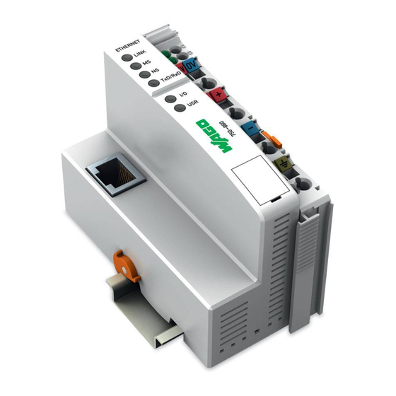
Page 47: View
• LEDs for status indication, i.e. operational status, fieldbus communication, operating voltages, error message and diagnostics • Configuration Interface • Selector switch • Electronics for communication with the I/O modules (internal bus) and the fieldbus interface WAGO-I/O-SYSTEM 750 Linux Fieldbus Coupler... -
Page 48: Power Supply
Fig. 3-2: Power supply, identical to 750-841 g086001d The integrated power supply provides the required power to the electronics and to the I/O modules. An electrically isolated power supply is provided to the fieldbus interface. WAGO-I/O-SYSTEM 750 Linux Fieldbus Coupler... -
Page 49: Fieldbus Connection Via The Ethernet Interface
Receive - Not assigned Not assigned Fig. 3-3: Fieldbus connection and pin assignment, RJ45 plug g034201d Attention The bus connection is only approved for use in LAN networks, not for the connection of telecommunication lines! WAGO-I/O-SYSTEM 750 Linux Fieldbus Coupler... -
Page 50: Display Elements
Status of operating voltage 24 V supply voltage of the Linux coupler. Green Status of operating voltage Power jumper contacts (field side supply) More information The evaluation of the LED signals is described in chapters 3.10 and 8.1. WAGO-I/O-SYSTEM 750 Linux Fieldbus Coupler... -
Page 51: Configuration Interface
Configuration Interface 3.5 Configuration Interface The configuration interface is located behind the cover flap. It is used for the communication with WAGO-I/O-CHECK and for the firmware download. It can be addressed under Linux via "ttyS0" device. Configuration and programming interface Fig. -
Page 52: Selector Switch
Function Upper position The Linux coupler is started with a Linux console on the serial interface (38400-8-N-1- NoFlowControl). Middle position WAGO program IO update is supported. Lower position Linux coupler starts Bootstrap Loader (BSL). Pressed down Hardware reset (e.g. using a screwdriver) -
Page 53: Hardware Address (Mac Id)
Hardware Address (MAC ID) 3.7 Hardware Address (MAC ID) Each WAGO Linux fieldbus coupler is provided from the factory with a unique and internationally unambiguous physical address, also referred to as MAC ID (Media Access Control Identity). This is located on the rear of the coupler and on a self-adhesive tear-off label on the coupler side. -
Page 54: Linux System Start
First, the firmware loader (FWL) is started via the WAGO bootstrap loader (BSL) which in turn will start the boot loader (U-Boot) for Linux. The BSL cannot be deleted. The FWL may only be exchanged by WAGO after prior consultation. -
Page 55: Error Indication (Io Led)
• After a break, the second blink sequence starts (approx. 1 Hz). The number of light pulses indicates the Error Code. • After another break, the third blink sequence starts (approx. 1 Hz). The number of light pulses indicates the Error Argument. WAGO-I/O-SYSTEM 750 Linux Fieldbus Coupler... - Page 56 (n+1)th I/O process data. module with process data and turn on the supply voltage again. Error code 6: Node configuration error Error during process image Reduce the number of I/O modules on the generation node WAGO-I/O-SYSTEM 750 Linux Fieldbus Coupler...
-
Page 57: Technical Data
EMC CE Emission of interference Acc. to EN 50081-2 (1994) Approvals (see chapter 2.2) (UL508) (UL1604) Class I Div2 ABCD T4A DEMKO II 3 G EEx nA II T4 Conformity marking Accessories Miniature WSB Quick marking system WAGO-I/O-SYSTEM 750 Linux Fieldbus Coupler... - Page 58 Voltage via power jumper contacts DC 24 V (-15 % ... + 20 %) Current via power jumper contacts DC 10 A Dimensions (mm) W x H x L 51 x 65* x 100 (*from upper edge of DIN 35 rail) Weight Approx. 180 g WAGO-I/O-SYSTEM 750 Linux Fieldbus Coupler...
-
Page 59: Board Support Package (Bsp)
The user space applications are an excellent starting point for the development of your own user space applications. The WAGO base image for the Linux fieldbus coupler is part of the BSP. The following chapters relate to this WAGO base image. - Page 60 Complete base image consisting of the file system, operating system, boot loader and firmware loader. Transfer to the Linux fieldbus coupler is done using the WAGO-IO- Update windows program. You will find further information on uboot in chapter 9 and on netflash in chapter 4.5.6...
- Page 61 Changes to the boot loader should only be made in some rare exeptions. • sources The uboot source code. The source code is unpacked by the install.sh script into the home directory of the current user. • toolchain Uboot toolchain. The install.sh script requires super user privileges. WAGO-I/O-SYSTEM 750 Linux Fieldbus Coupler...
-
Page 62: File System (Root File System)
Configuration files of the Web server dhcp Configuration files of the DHCP client wagoconsole Configuration files of the serial interface Device entries User programs for user The following gives a detailed description of the directories /proc, /etc and /bin. WAGO-I/O-SYSTEM 750 Linux Fieldbus Coupler... - Page 63 Kernel messages since system start • driver/kbus Information on the internal bus driver and its process image • Partitioning of the flash memory • stat CPU status • cpuinfo Information on the processor type WAGO-I/O-SYSTEM 750 Linux Fieldbus Coupler...
- Page 64 Contains the entries of the name servers • passwd User password file • services The port numbers are assigned to their corresponding services • group Configuration of the known user groups • TZ Time zone setting for all consoles WAGO-I/O-SYSTEM 750 Linux Fieldbus Coupler...
- Page 65 8) • wagoset Example for setting/reading the Ethernet configuration in the higher flash memory area (see chapter 4.6.2) • kbusdemo Demo program for reading or writing process data to the IO modules (see chapter 8) WAGO-I/O-SYSTEM 750 Linux Fieldbus Coupler...
-
Page 66: The Console Of The Linux Fieldbus Coupler
You can access the console via both the serial interface and the Ethernet interface. Before you can use the console, you need to enter a user name and a password: Fig. 4-1: Login of the console p086009d WAGO-I/O-SYSTEM 750 Linux Fieldbus Coupler... -
Page 67: Shells
It is a minix shell that supports more extensive script processing functions. The shell contains builtin commands, such as Furthermore, the Shell provides the environment variables and allows to navigate the file system as well as to run programs. WAGO-I/O-SYSTEM 750 Linux Fieldbus Coupler... -
Page 68: Busybox
• ifconfig View/change the current Ethernet settings. Changes are not accepted. Please use the wagoset program. • hostname Changes the local host name • syslogd Creates the log file /var/log/messages • modprobe Loads kernel modules WAGO-I/O-SYSTEM 750 Linux Fieldbus Coupler... - Page 69 PING service (Ethernet diagnostics service) • more Shows text files (page by page) • kill Unpacks a file in the user space • init Main process generates and manages all processes • grep Searches characters/strings in text files/directories WAGO-I/O-SYSTEM 750 Linux Fieldbus Coupler...
- Page 70 Lists all files of the current directory • ln Creates links • df Shows file system information (free memory) • cp Copies files • top Shows the system capacity occurring through each individual process (in %) WAGO-I/O-SYSTEM 750 Linux Fieldbus Coupler...
-
Page 71: User Administration (Tinylogin)
The table shows the users that are already stored (condition upon delivery). User Password Authorization root wago Super user admin wago Super user user user User has rights for HTML files guest guest Read rights WAGO-I/O-SYSTEM 750 Linux Fieldbus Coupler... -
Page 72: Terminal Program (Getty)
0: Day (0 = Sunday), on which time is set to daylight saving time. 10: Month, in which time is set to standard time. 5: Week, in which time is set to standard time. 0: Day (0 = Sunday), on which time is set to standard time. WAGO-I/O-SYSTEM 750 Linux Fieldbus Coupler... - Page 73 Hardware clock is set using the current system time • hwclock -l --localtime The hardware clock time is the local time • hwclock -u --utc The hardware clock time is Greenwich Time Example: hwclock -r Tue Feb 6 14:55:28 2007 0.000000 seconds WAGO-I/O-SYSTEM 750 Linux Fieldbus Coupler...
- Page 74 • date -r FILE Shows the last modification in the file FILE • date -u Sets the system time to Greenwich Time and displays it Example: date -d 05131045 Sun May 13 10:45:00 MESZ 2007 WAGO-I/O-SYSTEM 750 Linux Fieldbus Coupler...
-
Page 75: Web-Based Management (Wbm)
The status page shows the following values: Coupler details • Order description Description of the Linux fieldbus coupler • Order number Item number of the Linux fieldbus coupler • Firmware version Version of the implemented firmware WAGO-I/O-SYSTEM 750 Linux Fieldbus Coupler... - Page 76 Board Support Package (BSP) Web-Based Management (WBM) • FWL version Version of the implemented firmware loader • Serial number Wago serial number Network details • MAC address MAC address of the Linux fieldbus coupler • IP address The IP address which is currently used or assigned...
- Page 77 DNS server using short network names. For example: would not work since the complete name is ping pc1234 . If one or several "Default Search Domains" are pc1234.localdomain entered, the address will automatically change to pc1234 pc1234.localdomain WAGO-I/O-SYSTEM 750 Linux Fieldbus Coupler...
- Page 78 Activate the Ethernet device to use a static IP address • IP address Static IP address (if activated) • Subnet Mask Subnet mask (with static IP address) • Gateway Default gateway (with static IP address) WAGO-I/O-SYSTEM 750 Linux Fieldbus Coupler...
- Page 79 Linux fieldbus coupler since it is no longer possible to access the Linux coupler. A correction of the values is then only possible via the serial interface using the Linux console (see chapter 4.3, 4.6.1 and 4.6.2). WAGO-I/O-SYSTEM 750 Linux Fieldbus Coupler...
- Page 80 Fig. 4-5: Screen view "Kernel message" p086002d Among other things, you can find information on the hardware, on the installed Linux version, the drivers or on the IO modules that are connected to the Linux fieldbus coupler. WAGO-I/O-SYSTEM 750 Linux Fieldbus Coupler...
- Page 81 R EEPROM ESET button. After successful authentication the EEPROM will be erased. If the authentication was not successful, an error message will be displayed behind the text fields. WAGO-I/O-SYSTEM 750 Linux Fieldbus Coupler...
- Page 82 Item number of the IO module • Type The type of I/O module is indicated once more (see Color) • Number of channels Number of channels of the I/O module • Button „R“ Button to open the register tables WAGO-I/O-SYSTEM 750 Linux Fieldbus Coupler...
- Page 83 • Second column (for digital I/O modules: colored background, same color as LEDs) Value of the channel in the memory (Hex value) Light green: channel set Dark green: channel not set Gray: the LEDs only indicate readiness for operation, no channels set WAGO-I/O-SYSTEM 750 Linux Fieldbus Coupler...
- Page 84 Fig. 4-8: Screen view of Linux fieldbus coupler reboot p086004d The Root passord for the user "root" is stored in encoded form in the passwd file and is initially wago (condition upon delivery). Note The password is not transmitted via an encrypted connection. It can thus be seen and used by any other network participant.
-
Page 85: Ethernet Interface Services
The telnet daemon is started via Ethernet if requested. A new Linux console is created. The Linux console login and the login via the serial interface run simultaneously (see chapter 4.3). WAGO-I/O-SYSTEM 750 Linux Fieldbus Coupler... -
Page 86: Ftp Server (Ftpd)
To use FTP, run the FTP program via the DOS console when using the Windows operating system or via the Linux console when using Linux. To do so, enter ftp <hostname/IP> in the console and answer the questions about user and password (see following figure): WAGO-I/O-SYSTEM 750 Linux Fieldbus Coupler... - Page 87 The most convenient way to use FTP is to use an FTP client program such as Filezilla (http://sourceforge.net/projects/filezilla), which is distributed under the GPL. The FTP connection is established via port 21 which needs to be registered in some FTP clients . WAGO-I/O-SYSTEM 750 Linux Fieldbus Coupler...
-
Page 88: Ftp Client
What commands are supported by the server can be queried by the command: help. The server shows a list with all available FTP commands. help <command> you get a description of the queried command from the server. Example: help cd WAGO-I/O-SYSTEM 750 Linux Fieldbus Coupler... -
Page 89: Sntp Client (Msntp)
Do you want correct the time anyway? If you enter y, the time in the RTC chip and in the Linux kernel is changed via the internal function using the correction value of the settimeofday() previous query. WAGO-I/O-SYSTEM 750 Linux Fieldbus Coupler... - Page 90 • x 10 means that the process is a daemon and that it will take at least 10 minutes before it repeats its query. Further information on the parameters can be found on the msntp main page (e.g. under: http://pigtail.net/LRP/msntp.html). WAGO-I/O-SYSTEM 750 Linux Fieldbus Coupler...
-
Page 91: Http Server (Boa)
The BOA web server will run on startup (condition upon delivery). It provides a second graphical user interface via the web-based management system. The HTML and CGI pages that is described in chapter 4.4 are already stored. WAGO-I/O-SYSTEM 750 Linux Fieldbus Coupler... - Page 92 These files will output HTML code via the standard console "stdout" which will be transmitted via the WWW by the web server. Binary files are stored for the WAGO pages (delivery status) that write on standard output. The files are written using the C programming language. See also the example program in chapter 8.
-
Page 93: Netflash
Checks if the image was written correctly • Uses FTP as load protocol • Forces all areas (blocks) of the flash memory to be overwritten • Opens the help menu • Ignores all version information • Ignores the hardware type information WAGO-I/O-SYSTEM 750 Linux Fieldbus Coupler... - Page 94 –k –n –j –r /dev/mtd3 192.168.1.11 jffs2.img netflash: fetching file "jffs2.img" from 192.168.1.11 ..........................netflash: got "jffs2.img", length=1159368 netflash: flashing root filesystem, kill is forced Connection closed by foreign host. WAGO-I/O-SYSTEM 750 Linux Fieldbus Coupler...
-
Page 95: Ethernet Interface Services
4.3). A volatile IP adress can then be assigned in the console, e.g. (sets temporary IP address) > ifconfig eth0 192.168.1.4 Please use the wagoset program for a permanent configuration of the Ethernet interface. WAGO-I/O-SYSTEM 750 Linux Fieldbus Coupler... -
Page 96: Permanent Assignment Of The Ip Address (Wagoset)
Gateway; VALUE: x.x.x.x -o, --hostname Hostname; VALUE: [String Hostname] -h, --help Print this message. Send bug reports to support@wago.com Proprietary. To view the current settings use ./wagoset To start the Linux fieldbus coupler with IP address 192.168.1.4 during the next boot use the following command ./wagoset... -
Page 97: Dynamic Ip Address Assignment During Runtime
The programs bootpc for Bootp and dhcpcd for DHCP allow to boot up the kernel quickly and search the appropriate server using an individual process. During this time, the system can be used for other tasks. The programs are already available in the file system of the 750-860. WAGO-I/O-SYSTEM 750 Linux Fieldbus Coupler... - Page 98 Ethernet configuration. Start wagoset using the option -m none ~ # wagoset -h Usage: wagoset OPTION [VALUE] ... WAGO ETHERNET BOOT CONFIGURATION. OPTION: -v, --view View Configuration -m, --mode Ethernet Mode; VALUE: static, dhcp, bootp, none -i, --ip Static IP;...
-
Page 99: Checking The Network Connection
Should the error message: "Request timeout“, appear, please verify your input and compare it with the IP address you assigned. After a successful test, you can close the DOS prompt. The node is now ready to communicate. WAGO-I/O-SYSTEM 750 Linux Fieldbus Coupler... -
Page 100: Step-By-Step Guide To Your Own Linux Application
If you want to change or to compile the boot loader (U-Boot), you have to install a second toolchain. A pre-compiled version of the arm-elf toolchain for x86 systems is availabale under http://www.uclinux.org/pub/uClinux/m68k-elf-tools/, or on the Wago distribution CD under CD:/linux/toolchain/. The installation requires super user privileges. -
Page 101: Unpack The Source Code
Linux kernel, for the creation of the file system and for the compilation of the application programs. WAGO-I/O-SYSTEM 750 Linux Fieldbus Coupler... -
Page 102: Linux Kernel Compilation
The following attributes can be used: • all Synonym for: linux uClibc user romfs image • linux Kernel compilation • romfs Creates the root file system in the /romfs directory WAGO-I/O-SYSTEM 750 Linux Fieldbus Coupler... - Page 103 Invokes a menu-driven configuration of the Linux kernel, of the modules and of the application programs • clean Deletes all files that were created by compilation • distclean Deletes all files created by configuration and compilation WAGO-I/O-SYSTEM 750 Linux Fieldbus Coupler...
-
Page 104: Setup Of The Development Environment
• NFS server For easy file exchange with the Linux fieldbus coupler In order to update images for Bootloader, firmware and file system on the Linux fieldbus coupler you require a TFTP server. Please see chapter 9.2. WAGO-I/O-SYSTEM 750 Linux Fieldbus Coupler... -
Page 105: Pc Terminal Program Configuration (Serial)
To do so, start the program with the option "-s" and verify the settings in the menu item "Serial port setup". Fig. 5-1: Configuration of the serial interface in minicom p0860011d Press the <Strg> + <a><z> key combination to view a list with available functions. WAGO-I/O-SYSTEM 750 Linux Fieldbus Coupler... - Page 106 <a><t><b> key combination. In the Windows operating systems Hyperterminal is the recommended program for the serial terminal communication. The following figure shows the required settings. Fig. 5-2: Configuration of the serial interface in Hyperterminal p0860010d WAGO-I/O-SYSTEM 750 Linux Fieldbus Coupler...
-
Page 107: Pc Terminal Program Configuration (Ethernet)
In the "Connect to" dialog, select TCP/IP in the " Connect via" selection field. In the next window, enter the IP address (see also chapter 4.6) or the host name of the Linux fieldbus coupler and the port number 23 for Telnet. WAGO-I/O-SYSTEM 750 Linux Fieldbus Coupler... -
Page 108: Setting The Ip Address Of The Linux Fieldbus Coupler
In this way the settings are also available after the next start-up. (sets permanent IP address) > wagoset –i 192.168.1.8 Dynamic IP address assignment via DHCP for the next start of the Linux filedbus coupler can be set as follows: > wagoset –m dhcp WAGO-I/O-SYSTEM 750 Linux Fieldbus Coupler... -
Page 109: Create Your Own User Space Application
EMACS, KATE or JOE. > emacs newProg.c Call EMACS editor Insert the following code into the emacs and press CTRL-X CTRL-S to save int main (int argc, char **argv) printf(“Hello World\n“); WAGO-I/O-SYSTEM 750 Linux Fieldbus Coupler... - Page 110 This will also create a binary file newProg. At the same time, the romfs directory is updated and the new image of the file system jffs2.img is created which can be loaded via the boot loader (U-Boot) (see 5.10.2). WAGO-I/O-SYSTEM 750 Linux Fieldbus Coupler...
-
Page 111: Transferring The User Space Application To The Linux Coupler
FTP and then be executed locally. To do so, enter the following on the host > cd ~/uclinux-dist/user/newProg > ftp 192.168.1.8 root (Benutzer) wago (Passwort) > cd /bin > put newProg > quit Screenshot: Fig. 5-4: Linux screen view after program download p0860012 WAGO-I/O-SYSTEM 750 Linux Fieldbus Coupler... -
Page 112: Running The New Program
• sysinit Is started once during system start-up. • bootwait Is started once after all sysinit processes. • respawn Is restarted automatically if the process was terminated. Please refer to the initab manpage for more attributes. WAGO-I/O-SYSTEM 750 Linux Fieldbus Coupler... - Page 113 /bin/iocheck & insmod iocheck exit 0 During the start-up of the Linux fieldbus coupler, different programs are started or file attributes are changed. For example, the BOA web server and the Modbus program mb_tcp are started. WAGO-I/O-SYSTEM 750 Linux Fieldbus Coupler...
-
Page 114: File System And Linux Kernel Update
To open the console, enter the password geheim during the Linux coupler start-up. The boot process is aborted and the Linux fieldbus coupler opens the boot loader communication interface. You can use the macros for the update. update-kernel update-rootfs WAGO-I/O-SYSTEM 750 Linux Fieldbus Coupler... -
Page 115: Tftp Server Setup
In order to download the Linux kernel, the file system or the boot loader, it is essential to have a TFTP server on the development computer. You can find the original image files for the Wago Linux distribution under CD:/images/. -
Page 116: Tftp Client Setup
0x40000 jffs2.img;protect off 01:11-51;era 01:11-51;cp.b 0x40000 0x20040000 $(filesize) update-kernel=tf 0x40000 linux.flashme;protect off 01:52-69;era 01:52-69;cp.b 0x40000 0x202d0000 $(filesize) update-ub=tf 0x40000 ub.bin;protect off 01:08-9;era 01:08- 9;cp.b 0x40000 0x20010000 $(filesize) bootA=setenv bootargs $(bootargs) wago_console=yes ip=$(ipmode) $(output);bootm bootB=setenv bootargs $(bootargs) ip=$(ipmode) $(output);bootm WAGO-I/O-SYSTEM 750 Linux Fieldbus Coupler... - Page 117 These macros execute the following U-Boot commands: 1. Load image file into the memory via TFTP. 2. Disable write protection on flash memory. 3. Delete designated area of the flash memory. 4. Copy image file into flash memory. WAGO-I/O-SYSTEM 750 Linux Fieldbus Coupler...
- Page 118 Erasing sector 56 ... ok. Erasing sector 57 ... ok. Erasing sector 58 ... ok. Erasing sector 59 ... ok. Erasing sector 60 ... ok. Erasing sector 61 ... ok. Erasing sector 62 ... ok. WAGO-I/O-SYSTEM 750 Linux Fieldbus Coupler...
- Page 119 A JFFS2 image of the file system is called jffs2.img and the kernel file with bootloader header is called linux.flashme. The files are available on the WAGO Linux distribution CD under CD:/images/ and must be copied into the /tftpboot/ directory first or be generated in the uClinux directoty using make.
-
Page 120: Nfs Server Setup
To serve this purpose, the Linux coupler provides the /nfs drive (delivery status). The drive can be accessed like a local drive. If drives are to be linked automatically during system start-up, they must be entered in the /etc/rc file. WAGO-I/O-SYSTEM 750 Linux Fieldbus Coupler... -
Page 121: Debugging Of User Space Programs
However, there are also graphical front ends to GDB, such as DDD (Data Display Debugger). This graphical user interface allows the use of GDB in the same way as in an integrated development environment. WAGO-I/O-SYSTEM 750 Linux Fieldbus Coupler... -
Page 122: Preparation For Using The Debugger
2. A search window opens. Enter DDD and press the Enter key. 3. If the search result shows the DDD application, install it. If the DDD is not in the distribution, it can be downloaded at: www.gnu.org/software/ddd/. WAGO-I/O-SYSTEM 750 Linux Fieldbus Coupler... -
Page 123: Creating A Testable User Space Application
3. The following question appears "Do you wish to save your kernel configurations?". Click on YES. 4. Another menu opens. Select “Debug Builds” and press the Enter key. 5. Select “Build debuggable applications” and press the space bar. WAGO-I/O-SYSTEM 750 Linux Fieldbus Coupler... - Page 124 For final release versions of the programs, it is advisable to cancel the above setting (“Build debuggable applications”) and completely compile the program once more. To do so use the following calls: > make clean > make (or make user). WAGO-I/O-SYSTEM 750 Linux Fieldbus Coupler...
-
Page 125: Creating An Example Application For Debugging
Add the following calls to the source codes: > cd ~/uclinux-dist/user/newProg > emacs newProg.c Enter the following code into the emacs and save it via CTRL-X, CTRL-S: void printfunc(void) int i = 3; printf("WAGO world\n"); printf("%d..", i); i--; printf("%d..", i); i--; printf("%d..\n", i); return;... -
Page 126: Debugging Via The Gdb Console
First, start the GDB server on the Linux fieldbus controller. To do so, change the directory in which is the program that has been created in the previous section: > cd ~/uclinux-dist/user/newProg Enter the following call into the console: > gdbserver 192.168.1.4:1234 newProg WAGO-I/O-SYSTEM 750 Linux Fieldbus Coupler... - Page 127 The program is executed until the next program line is reached. Skips subroutines. nexti The program is executed until the next assembler code line. Skips subroutines. continue Continues to execute the program. The next breakpoint or pressing STRG+C tops the execution. WAGO-I/O-SYSTEM 750 Linux Fieldbus Coupler...
- Page 128 Linux fieldbus controller. Debugging via the console is not a very convenient way of doing it, however, it offers a very good opportunity to control user space programs of the Linux fieldbus controller via a PC. WAGO-I/O-SYSTEM 750 Linux Fieldbus Coupler...
-
Page 129: Debugging Via The Graphical Interface Ddd
192.168.1.4. The graphical interface DDD and the debugger GDB will be started on the Linux PC when you enter the following calls into the console: > cd ~/uclinux-dist/user/newProg > ddd newProg.gdb --command=gdb.script --degugger arm-uclinux-elf-gdb --gdb WAGO-I/O-SYSTEM 750 Linux Fieldbus Coupler... - Page 130 126 • Step-by-Step Guide to your own Linux Application Debugging of User Space Programs Fig. -: DDD: Graphical interface of the debugger DDD now offers all the features of an integrated development environment. The operation is not described further in this manual. WAGO-I/O-SYSTEM 750 Linux Fieldbus Coupler...
-
Page 131: Process Image
The node can consist of a mixed arrangement of a maximum of 64 analog and digital I/O modules. Note The use of the WAGO module bus extension coupler module 750-628 and end module 750-627 makes it possible to connect up to 750 modules to the Linux fieldbus coupler 841-250. -
Page 132: Example For An Input Process Image
… … … … Byte 1 0x000C 0x000D Byte 2 Byte1 0x000E Byte 3 Byte2 0x000F Byte 4 DI: Digital Input AI: Analog Input 0x0010 0x0011 Fig. 6-1: Example of an input process image g086015d WAGO-I/O-SYSTEM 750 Linux Fieldbus Coupler... -
Page 133: Example For An Output Process Image
0x0002 Byte2 Byte 4 0x0003 Byte 1 0x0004 Byte 2 0x0005 Byte1 Byte 3 0x0006 Byte2 Byte 4 0x0007 0x0008 DO: Digital Output AO: Analog Output Fig. 6-2: Example of an output process image g086058d WAGO-I/O-SYSTEM 750 Linux Fieldbus Coupler... -
Page 134: Application Example For A Mixed Node
Byte 3 0x0002 Byte2 0x0003 Byte 4 0x0004 DI : Digital Input Module AI : Analog Input Module DO: Digital Output Module AO: Analog Output Module Fig. 6-3: Addressing example for a fieldbus node g086058d WAGO-I/O-SYSTEM 750 Linux Fieldbus Coupler... -
Page 135: Internal Bus Driver (Kbus.ko)
I/O modules. • ioctl(iFD, IOCTL_GETBININPUTOFFSET, &ulInputOffset) Reads out the value. The first digital input module in the input Offset process image has the value. It is therefore easier to access the Offset digital I/O modules. WAGO-I/O-SYSTEM 750 Linux Fieldbus Coupler... - Page 136 Before the input process image can be analyzed, ioctl(iFD, must be called. After changing the output process IOCTL_KBUSUPDATE,...) image, it is also required to call ioctl(iFD, IOCTL_KBUSUPDATE,...) order to send the new values to the modules. WAGO-I/O-SYSTEM 750 Linux Fieldbus Coupler...
- Page 137 The following example shows how to set a bit: Using the pstPabOut->uc.Pab[0]|= 0x08; sample code allows you to perform a boolian OR operation of the value 0x08 with the output process image which sets the bit 0.3 ('0000.10') to TRUE. WAGO-I/O-SYSTEM 750 Linux Fieldbus Coupler...
- Page 138 Example: word query The following example shows how to query a word: Using the if (pstPabIn->us.Pab[0] == 0x0008) sample code allows you to check whether the 0-bit process array (us) has the value 0x0008 WAGO-I/O-SYSTEM 750 Linux Fieldbus Coupler...
-
Page 139: Process Image Analysis Via The /Proc Directory
PAB Size: 2040 bytes PAB Out: 00ffe858 PAB Size: 2040 bytes Position after the Linux coupler Slot Item number Terminal No data in the input process image Base addresses of the process images PAB IN, PAB OUT WAGO-I/O-SYSTEM 750 Linux Fieldbus Coupler... -
Page 140: O Modules
You will find these manuals on CD ROM „ELECTRONICC Tools and Docs“ (Item No.: 0888-0412) or at http://www.wago.com under Documentation. More Information Current information on the modular WAGO-I/O-SYSTEM is available at http://www.wago.com. 7.1.1 Digital Input Modules Tab. 7-1: Digital input modules DI DC 5 V 750-414 4 Channel, DC 5 V, 0.2 ms, 2- to 3-conductor connection,... - Page 141 2 Channel, AC 120 V, 2- to 4-conductor connection; high-side switching DI AC 120(230) V 753-440 4 Channel, AC 120(230) V, 2-conductor connection; high-side switching DI AC 230 V 750-405, 753-405 2 Channel, AC 230 V, 2- to 4-conductor connection; high-side switching WAGO-I/O-SYSTEM 750 Linux Fieldbus Coupler...
-
Page 142: Digital Output Modules
8 Channel, DC 24 V, 0.5 A, short-circuit-protected; high-side switching; diagnostics 750-536 8 Channel, DC 24 V, 0.5 A, short-circuit-protected; low-side switching DO AC 120(230) V 753-540 4 Channel, AC 120(230) V, 0.25 A, short-circuit-protected; high-side switching WAGO-I/O-SYSTEM 750 Linux Fieldbus Coupler... -
Page 143: Analog Input Modules
4 Channel, 4 - 20 mA, single-ended AI 0 - 1 A 750-475, 753-475 2-Channel, 0 - 1 A AC/DC, differential input AI 0 - 5 A 750-475/020-000, 2-Channel, 0 - 5 A AC/DC, differential input 753-475/020-000 WAGO-I/O-SYSTEM 750 Linux Fieldbus Coupler... - Page 144 J, K, B, E, N, R, S, T, U 750-469, 753-469 2 Channel, thermocouples, line break detection, sensor types: J, K, B, E, N, R, S, T, U, L AI Others 750-491 1 Channel for resistor bridges (strain gauge) WAGO-I/O-SYSTEM 750 Linux Fieldbus Coupler...
-
Page 145: Analog Output Modules
2 Channel, DC 0 - 10 V, 10 bit, 100 mW, 24 V 750-559, 753-559 4 Channel, DC 0 - 10 V AO DC ± 10 V 750-556, 753-556 2 Channel, DC ± 10 V 750-557, 753-557 4 Channel, DC ± 10 V WAGO-I/O-SYSTEM 750 Linux Fieldbus Coupler... -
Page 146: Special Modules
AS interface master module Radio Receiver Module 750-642 Radio receiver EnOcean MP Bus Master Module 750-643 MP bus (multi point bus) master module Vibration Monitoring 750-645 2 Channel vibration velocity / bearing condition monitoring VIB I/O WAGO-I/O-SYSTEM 750 Linux Fieldbus Coupler... - Page 147 1FDO 10A / 2FDO 0.5A / 2FDI 24V PROFIsafe; PROFIsafe power switch module RTC Module 750-640 RTC module KNX / EIB TP1 Module 750-646 KNX / EIB /TP1 module – device mode / router mode WAGO-I/O-SYSTEM 750 Linux Fieldbus Coupler...
-
Page 148: System Modules
Field side connection module, AC/DC 0 ... 230 V Separation Modules 750-616 Separation module 750-621 Separation module with power contacts Binary Spacer Module 750-622 Binary spacer module End Module 750-600 End module, to loop the internal bus WAGO-I/O-SYSTEM 750 Linux Fieldbus Coupler... -
Page 149: Process Data Architecture For Modbus/Tcp
(with word alignment). The internal mapping method for data greater than one byte conforms to the Intel format. The following section describes the process image for various WAGO-I/O-SYSTEM 750 and 753 I/O modules when using a coupler/controller with MODBUS/TCP. Note... - Page 150 Channel Output Process Image Bit 7 Bit 6 Bit 5 Bit 4 Bit 3 Bit 2 Bit 1 Bit 0 Acknowledge Acknowledg ment bit ement bit Channel 2 Channel 1 4 Channel Digital Input Modules WAGO-I/O-SYSTEM 750 Linux Fieldbus Coupler...
-
Page 151: Digital Output Modules
Bit 2 Bit 1 Bit 0 controls DO 1 used Channel 1 2 Channel Digital Output Modules 750-501, -502, -509, -512, -513, -514, -517, -535, (and all variations), 753-501, -502, -509, -512, -513, -514, -517 WAGO-I/O-SYSTEM 750 Linux Fieldbus Coupler... - Page 152 (i.e., overload, a short circuit, or a broken wire). The 4-bits of diagnostic data are mapped into the Input Process Image, while the output control bits are in the Output Process Image. WAGO-I/O-SYSTEM 750 Linux Fieldbus Coupler...
- Page 153 S 3 ic bit S 2 ic bit S 1 c bit S 0 Channel Channel Channel Channel Diagnostic bit S = '0' no Error Diagnostic bit S = '1' overload, short circuit, or broken wire WAGO-I/O-SYSTEM 750 Linux Fieldbus Coupler...
- Page 154 Bit 1 Bit 0 controls controls controls controls controls controls controls controls DO 8 DO 7 DO 6 DO 5 DO 4 DO 3 DO 2 DO 1 Channel Channel Channel Channel Channel Channel Channel Channel WAGO-I/O-SYSTEM 750 Linux Fieldbus Coupler...
-
Page 155: Analog Input Modules
753-452, -454, -456, -461, -465, -466, -467, -469, -472, -474, -475, -476, - 477, -478, -479, -483, -492, (and all variations) Input Process Image Byte Destination Offset Remark High Byte Low Byte Measured Value Channel 1 Measured Value Channel 2 WAGO-I/O-SYSTEM 750 Linux Fieldbus Coupler... -
Page 156: Analog Output Modules
2 Channel Analog Output Modules 750-550, -552, -554, -556, -560, -585, (and all variations), 753-550, -552, -554, -556 Output Process Image Byte Destination Offset Remark High Byte Low Byte Output Value Channel 1 Output Value Channel 2 WAGO-I/O-SYSTEM 750 Linux Fieldbus Coupler... -
Page 157: Specialty Modules
Output Value Channel 4 7.2.5 Specialty Modules WAGO has a host of Specialty I/O modules that perform various functions. With individual modules beside the data bytes also the control/status byte is mapped in the process image. The control/status byte is required for the bi-directional data exchange of the module with the higher-ranking control system. - Page 158 Counter Value of Counter 1 Counter Value of Counter 2 Output Process Image Byte Destination Offset Remark High Byte Low Byte Control byte Counter Setting Value of Counter 1 Counter Setting Value of Counter 2 750-638, 753-638 WAGO-I/O-SYSTEM 750 Linux Fieldbus Coupler...
- Page 159 The two channel values are supplied as 16 bits. Each channel has its own control/status byte. The following table illustrates the Input and Output Process Image, which has a total of 4 words mapped into each image. Word alignment is applied. WAGO-I/O-SYSTEM 750 Linux Fieldbus Coupler...
- Page 160 Input and Output Process Image, which have a total of 2 words mapped into each image. Word alignment is applied. Input and Output Process Image Byte Destination Offset Remark High Byte Low Byte Data byte Control/Status byte Data bytes WAGO-I/O-SYSTEM 750 Linux Fieldbus Coupler...
- Page 161 Input and Output Process Image. The following tables illustrate the Input and Output Process Image, which has a total of 2 words mapped into each image. Word alignment is applied. Input and Output Process Image Byte Destination Offset Remark High Byte Low Byte Data bytes WAGO-I/O-SYSTEM 750 Linux Fieldbus Coupler...
- Page 162 High Byte Low Byte not used Status byte Counter word not used Latch word Output Process Image Byte Destination Offset Remark High Byte Low Byte not used Control byte Counter Setting word not used not used WAGO-I/O-SYSTEM 750 Linux Fieldbus Coupler...
- Page 163 Input and Output Process Image Byte Destination Offset Remark High Byte Low Byte C0/S0 Control/Status byte of Channel 1 Data Value of Channel 1 C1/S1 Control/Status byte of Channel 2 Data Value of Channel 2 WAGO-I/O-SYSTEM 750 Linux Fieldbus Coupler...
- Page 164 Input and Output Process Image (5 bytes of module data and 1 byte of control/status). The following tables illustrate the Input and Output Process Image, which have 3 words mapped into each image. Word alignment is applied. WAGO-I/O-SYSTEM 750 Linux Fieldbus Coupler...
- Page 165 Input Process Image Byte Destination Offset Remark High Byte Low Byte Data byte Status byte Data bytes Output Process Image Byte Destination Offset Remark High Byte Low Byte not used Control byte not used WAGO-I/O-SYSTEM 750 Linux Fieldbus Coupler...
- Page 166 Image, which have 4 words mapped into each image. Word alignment is applied. Input and Output Process Image Byte Destination Offset Remark High Byte Low Byte extended Control/Status C1/S1 C0/S0 Control/Status byte byte Data bytes WAGO-I/O-SYSTEM 750 Linux Fieldbus Coupler...
- Page 167 Not used (log. Channel 3 Sensor input 1) Data bytes (log. Channel 3 Sensor input 1) Control/Status byte C3/S3 Not used (log. Channel 4 Sensor input 2) Data bytes (log. Channel 4 Sensor input 2) WAGO-I/O-SYSTEM 750 Linux Fieldbus Coupler...
- Page 168 The following words contain the remaining process data. Input and Output Process Image Byte Destination Offset Remark High Byte Low Byte C0/S0 not used Control/Status byte Mailbox (0, 3, 5, 6 or 9 words) / Process data (0-16 words) max. 23 WAGO-I/O-SYSTEM 750 Linux Fieldbus Coupler...
-
Page 169: System Modules
Bit 1 Bit 0 (Data bit (Data bit (Data bit (Data bit (Data bit (Data bit Data bit Data bit DI 8) DI 7) DI 6) DI 5) DI 4) DI 3) DI 2 DI 1 WAGO-I/O-SYSTEM 750 Linux Fieldbus Coupler... -
Page 170: Application Examples
The example programs are a basis for developing your own applications. In order to keep it clear and simple, we left out error handling for the most part, however, it should be implemented to use the code. WAGO-I/O-SYSTEM 750 Linux Fieldbus Coupler... -
Page 171: Led Indication Example
Fig. 8-1: Display elements of the fieldbus coupler g086002x Color Signification STATUS Green/Red Function can be defined by the user. SERVICE Green/Red Function can be defined by the user. Green/Red Function can be defined by the user. WAGO-I/O-SYSTEM 750 Linux Fieldbus Coupler... - Page 172 User LED (red) User LED (green) All LEDs Proprietary. Send bug reports to support@wago.com Different OPTIONS/commands can be sent to the LEDs via the example program. The LEDs can be turned on or off or they can blink. Each OPTION requires an LEDNAME in order to define to which LED the OPTION/function is applied.
- Page 173 Using these definitions, you can assign a function to every LED. Additionally, the following LED names are defined which can be used to access the appropriate LED: #define WAGO_FBK_LED_DEBUG1_RED #define WAGO_FBK_LED_DEBUG1_GREEN #define WAGO_FBK_LED_DEBUG2_RED #define WAGO_FBK_LED_DEBUG2_GREEN #define WAGO_FBK_LED_USER_RED #define WAGO_FBK_LED_USER_GREEN #define WAGO_FBK_LED_ALL WAGO-I/O-SYSTEM 750 Linux Fieldbus Coupler...
- Page 174 The leds.c file contains the main() function. The console entries are analyzed and the macro (which is defined in leds.h) with its parameter ledman_cmd() values is called. The help text for the option "-help" is also defined here. WAGO-I/O-SYSTEM 750 Linux Fieldbus Coupler...
-
Page 175: Example Kbusdemo
In order to illustrate the driver interface, the Linux coupler incorporates the kbusdemo example program. This program can read or write the state/data of the internal bus via the Linux console. WAGO-I/O-SYSTEM 750 Linux Fieldbus Coupler... - Page 176 Print this message. ADDRESS: xxx.x Startaddress (Byte.Bit) from Output/Input Send bug reports to support@wago.com Proprietary. Via the OPTIONS of this example program it is possible to select whether to read or to write data. The ADDRESS field determines the corresponding address.
- Page 177 The bit for the output address 1.7 in the process image is set to FALSE ./kbusdemo Reads the data at input byte 0 Output: IN[0]: 0b10100000 IN[0]: 0xa0 The first byte has the following format: IN[Byte] binary - || IN[Byte] hexadecimal output WAGO-I/O-SYSTEM 750 Linux Fieldbus Coupler...
- Page 178 The console output is generated like the help text in that file. Source code description: kbusapi.h This header file contains definitions that make it easier to access the kbus.o driver. Source code description: kbusapi.c The accesses from the kbusapi.h file are coded in the kbusapi.c file. WAGO-I/O-SYSTEM 750 Linux Fieldbus Coupler...
-
Page 179: Example Of A Modbus Tcp Server
Discrete reading of several input bits 0x03 Read Multiple Registers Reading several input registers FC4: 0x04 Read InputRegisters Reading several input registers FC5: 0x05 Write Coil Writing a single output bit FC6: 0x06 Write SingleRegister Writing a single output register WAGO-I/O-SYSTEM 750 Linux Fieldbus Coupler... - Page 180 TCP server is only supposed to illustrate a more complex application on the Linux fieldbus coupler. Furthermore, the program is used to conduct a functional test of the Linux coupler and is hence installed on every coupler. The customer can change or extend the source code arbitrarily. WAGO-I/O-SYSTEM 750 Linux Fieldbus Coupler...
-
Page 181: Example Program For A Cgi Application
CGI call administration is ideal if you only want to need little memory in the file system for the files to be called. It is furthermore possible to exchange the entire functionality of the CGI calls by only replacing one file (see also chapter 4.5.5). WAGO-I/O-SYSTEM 750 Linux Fieldbus Coupler... - Page 182 Source code description: *.html The above-mentioned HTML pages contain the general web page layout of the WAGO internet pages. The Index.html file divides the web page into three sections: one part for the headline, one part for the left selection menu and one for the dynamic part in the middle.
- Page 183 These environment variables are in the highest flash memory sector and are read by the boot loader (U-Boot). reads the IP addresses of the name servers from the read_file() /etc/resolv.conf file. The function writes the IP addresses of the name servers into write_file() the /etc/resolv.conf file. WAGO-I/O-SYSTEM 750 Linux Fieldbus Coupler...
- Page 184 Furthermore, the query string including the password is analyzed. After entering a user with root privileges and the corresponding password (default:user name: root, password: wago) and clicking the R button, EBOOT will be called which will reboot the operating system.
- Page 185 • printSpecial() • main_config() function outputs the standard parameters of an IO printStandard() module (type, slot number etc.). function displays the special printAnalogOutput() Input() parameters of the individual analog modules separately in pop-up tables. WAGO-I/O-SYSTEM 750 Linux Fieldbus Coupler...
- Page 186 (specialty modules) separately in pop-up tables. function initializes that part of the pop-up table which main_config() needs to be opened. For that purpose, the submit buttons are analyzed. WAGO-I/O-SYSTEM 750 Linux Fieldbus Coupler...
-
Page 187: Example Of Reading And Writing From The Nvram
File descriptor returned by the function. open buf: A pointer to the buffer from which to write the data to the memory. count: Number of bytes to be written. WAGO-I/O-SYSTEM 750 Linux Fieldbus Coupler... - Page 188 SEEK_CUR: Within the file, both read/write operations start from the current position + offset value. SEEK_END: Within the file, both read/write operations start from the last byte + offset value (here the offset is usually "0" or negative value). WAGO-I/O-SYSTEM 750 Linux Fieldbus Coupler...
- Page 189 += 1; /*Write into Device*/ if(-1 == lseek(file, 0, SEEK_SET)) printf(“ERROR: lseek failed\n”); sstmp = write(file, buf, 8); printf(“Write (%d) bytes\n”, sstmp); if(sstmp != 8) printf(“ERROR: Writing into Device failed\n”); /*close device*/ close(file); WAGO-I/O-SYSTEM 750 Linux Fieldbus Coupler...
-
Page 190: Bootloader (U-Boot)
The boot loader requires a special toolchain which is called "DENX Embedded Linux Development Kit" (ELDK). A pre-compiled version for x86 host systems is available under: ftp://ftp.leo.org/pub/eldk/2.1.0/eldk-arm- linux-x86/ or on the WAGO distribution CD-ROM under CD:/toolchain/uboot/. You install the toolchain and the other utility programs in the super user mode with the following command: >... -
Page 191: Tftp Server Setup
/etc/inetd.conf: <host-ip>:tftp dgram udp wait root /usr/sbin/in.tftpd -s /tftpboot inetd starts automatically after a reboot or it can be started manually: > /etc/init.d/inetd start or restarted with > /etc/init.d/inetd stop > /etc/init.d/inetd start WAGO-I/O-SYSTEM 750 Linux Fieldbus Coupler... -
Page 192: Unpack The Source Code
Linux distribution (see chapter 5.3). A boot loader image is created during the compilation of the boot loader U-Boot. The files are automatically copied into the /tftpboot directory which has to be created beforehand. See chapter 9.2. WAGO-I/O-SYSTEM 750 Linux Fieldbus Coupler... -
Page 193: Environment Variables
Macros that, depending on the selector switch position of the Linux fieldbus coupler, are copied to bootcmd when U-Boot is started. • bootdelay The time the system waits for the abort password to arrrive • ethaddr MAC address of the Linux fieldbus coupler WAGO-I/O-SYSTEM 750 Linux Fieldbus Coupler... - Page 194 • baudrate Baud rate of the serial interface An update of the environment variables via the Linux operating system is executed via the device interface /dev/mtdblock5. The wagoset example program was developed for this purpose. WAGO-I/O-SYSTEM 750 Linux Fieldbus Coupler...
-
Page 195: Fieldbus Communication
The TCP/IP protocol stack offers a high degree of reliability for the transmission of information. In the ETHERNET based (programmable) fieldbus couplers and controllers developed by WAGO, usually various application protocols have been implemented on the basis of the TCP/IP stack. These protocols allow the user to create applications (master applications) with standardized interfaces and transmit process data via an ETHERNET interface. -
Page 196: Network Architecture - Principles And Regulations
192 • Fieldbus Communication ETHERNET The WAGO ETHERNET TCP/IP fieldbus node does not require any additional master components other than a PC with a network card. So, the fieldbus node can be easily connected to local or global networks using the fieldbus connection. -
Page 197: Transmission Media
For thin coaxial cable, the “2” is rounded up from the 185 meter maximum length for individual thin coaxial segments. The “T” and “F” stand for ‘twisted pair’ and ‘fiber optic’, and simply indicate the cable type. WAGO-I/O-SYSTEM 750 Linux Fieldbus Coupler... - Page 198 “data traffic cop” where the hub “polices” the data coming in and going out of the individual ports, so the data will only be transmitted to the required node. WAGO recommends using a switch rather then a hub, this will allow for a more deterministic architecture.
-
Page 199: Network Topologies
Stations can be added or removed without network interruption. Moreover, in the event of a defective cable, only the network segment and the node connected to this segment is impaired. This considerably increases the fail-safe of the entire network. WAGO-I/O-SYSTEM 750 Linux Fieldbus Coupler... - Page 200 Tree topologies allow for the expansion of an existing network, and enables schools, etc. to configure a network to meet their needs. Fig. 10-5: Tree Topology G012904e WAGO-I/O-SYSTEM 750 Linux Fieldbus Coupler...
- Page 201 Specifications may vary depending on the selected topology, the transmission media and coupler modules used in industrial environments, as well as the use of components from different manufacturers in a network. Therefore, the specifications given here are only intended as recommendations. WAGO-I/O-SYSTEM 750 Linux Fieldbus Coupler...
-
Page 202: Coupler Modules
Tab. 10-2: Comparison of Coupler Modules for Networks 10.1.2.4 Transmission Mode Some ETHERNET based WAGO couplers/controllers support both 10Mbit/s and 100Mbit/s for either full or half duplex operation. To guarantee a safe and fast transmission, both these couplers/controllers and their link partners must be configured for the same transmission mode. - Page 203 If the device is operating duplex operation. in full-duplex mode with static configuration, a duplex mode mismatch will occur (see above). WAGO-I/O-SYSTEM 750 Linux Fieldbus Coupler...
-
Page 204: Important Terms
Collisions may occur and messages have to be repeatedly transmitted as a result of the large amount of data traffic. The delay time in a Shared ETHERNET cannot be easily calculated or predicted. Fig. 10-6: Principle of Shared ETHERNET G012910e Deterministic ETHERNET WAGO-I/O-SYSTEM 750 Linux Fieldbus Coupler... - Page 205 The message is then only sent to the node with the correct target address. This reduces the data traffic over the network, extends the bandwidth and prevents collisions. The runtimes can be defined and calculated, making the Switched Ethernet deterministic. Fig. 10-7: Principle of Switched ETHERNET G012909e WAGO-I/O-SYSTEM 750 Linux Fieldbus Coupler...
-
Page 206: Network Communication
IP layer. In contrast to the TCP protocol, UDP is not connection oriented. That means there are no monitoring mechanisms for data exchange between sender and receiver. The advantage of this protocol is in the efficiency of the transmitted WAGO-I/O-SYSTEM 750 Linux Fieldbus Coupler... - Page 207 Application device profiles (e.g. positioning controllers, semi- conductors, pneumatic valves) CIP application objects library CIP data management services (explicit messages, I/O messages) CIP message routing, connection management Encapsulation protocol TCP, UDP Ethernet (physical interface, CSMA/CD) WAGO-I/O-SYSTEM 750 Linux Fieldbus Coupler...
-
Page 208: Communication Protocols
Fieldbus Communication ETHERNET 10.1.3.2 Communication Protocols In addition to the ETHERNET standard, the following important communication protocols are implemented in the WAGO ETHERNET based (programmable) fieldbus couplers and controllers: • IP Version 4 (Raw-IP and IP-Multicast ) • TCP • UDP •... -
Page 209: Channel Access Method
The address has a fixed length of 6 Bytes (48 Bit) and contains the address type, the manufacturer’s ID, and the serial number. Examples for the MAC-ID of a WAGO ETHERNET fieldbus coupler (hexadecimal): 00 ETHERNET does not allow addressing of different networks. - Page 210 The highest bit in Class A networks is always ‘0’. Meaning the highest byte can be in a range of ’0 0000000’ to ‘0 1111111’. Therefore, the address range of a Class A network in the first byte is always between 0 and 127. WAGO-I/O-SYSTEM 750 Linux Fieldbus Coupler...
- Page 211 Class C 192.000.000.XXX - Ca. 2 million 223.255.255.XXX Each WAGO ETHERNET (programmable) fieldbus coupler or controller can be easily assigned an IP address via the implemented BootP protocol. For small internal networks we recommend selecting a network address from Class C.
- Page 212 • Class C Subnet mask: .255 .255 Depending on the subnet division the subnet masks may, however, contain other values beyond 0 and 255, such as 255.255.255.128 or 255.255.255.248. Your network administrator allocates the subnet mask number to you. WAGO-I/O-SYSTEM 750 Linux Fieldbus Coupler...
- Page 213 IP-Header IP-Data Fig. 10-11: IP Packet The most important information in the IP header is the IP address of the transmitter and the receiver and the transport protocol used. WAGO-I/O-SYSTEM 750 Linux Fieldbus Coupler...
- Page 214 The result is known as the acknowledgement number and is returned with the next self-sent packet as an acknowledgement. This ensures that the lost TCP packets are detected and resent, if necessary, in the correct sequence. WAGO-I/O-SYSTEM 750 Linux Fieldbus Coupler...
- Page 215 This protocol combines the IP address with the physical MAC address of the respective Ethernet card. It is always used when data transfer to an IP address takes place in the same logical network in which the sender is located. WAGO-I/O-SYSTEM 750 Linux Fieldbus Coupler...
-
Page 216: Administration And Diagnosis Protocols
The dynamic configuration of the IP address via a BootP server offers the user a flexible and simple design of his network. The WAGO BootP server allows any IP address to be easily assigned for the WAGO (programmable) fieldbus coupler or controller. - Page 217 (e.g. whether IP configuration of the coupler/controller is to be performed via the DHCP protocol, the BootP protocol or from the data stored in the EEPROM). The HTTP server uses port number 80. WAGO-I/O-SYSTEM 750 Linux Fieldbus Coupler...
- Page 218 IP address. The time for the renewing should be about one half of the lease time. The rebinding time should be about of the lease time. WAGO-I/O-SYSTEM 750 Linux Fieldbus Coupler...
- Page 219 RAM disk. To permanently store the data of the RAM disk, the information is additionally copied into the flash memory. The data is stored in the flash after the file has been closed. Due to the storage process, access times during write cycles are long. WAGO-I/O-SYSTEM 750 Linux Fieldbus Coupler...
- Page 220 The TFTP (Trival File Transfer Protocol) is not supported by some of the couplers/controllers. More information You can find a list of the exact available implemented protocols in the chapter "Technical Data" to the fieldbus coupler and/or controller. WAGO-I/O-SYSTEM 750 Linux Fieldbus Coupler...
-
Page 221: Application Protocols
Thus the user is able to have a simple access from the respective fieldbus on the fieldbus node. There are based on ETHERNET couplers/controllers available developed by WAGO, with the following possible application protocols: • MODBUS TCP (UDP) •... -
Page 222: Use In Hazardous Environments
This is backed by law, directives or regulations on a national and international scale. WAGO-I/O-SYSTEM 750 (electrical components) is designed for use in zone 2 explosive environments. The following basic explosion protection related terms have been defined. - Page 223 • Zone 21 areas can expect the occasional occurrence of an explosive atmosphere (> 10 h ≤ 1000 h /year). • Zone 22 areas can expect the rare or short-term occurrence of an explosive atmosphere (> 0 h ≤ 10 h /year). WAGO-I/O-SYSTEM 750 Linux Fieldbus Coupler...
-
Page 224: Explosion Protection Group
Minimal Ignition Energy of Representative Types of Gases Explosion group Gases Methane Propane Ethylene Hydrogen Ignition energy (µJ) Hydrogen being commonly encountered in chemical plants, frequently the explosion group IIC is requested for maximum safety. WAGO-I/O-SYSTEM 750 Linux Fieldbus Coupler... -
Page 225: Unit Categories
Zone 1 Explosive environment by gas, fumes or mist Zone 2 Explosive environment by gas, fumes or mist Zone 20 Explosive environment by dust Zone 21 Explosive environment by dust Zone 22 Explosive environment by dust WAGO-I/O-SYSTEM 750 Linux Fieldbus Coupler... -
Page 226: Temperature Classes
Tab. 11-4: Material groups in percent Temperature classes Total 26.6 % 42.8 % 25.5 % 94.9 % 4.9 % 0.2 % Explosion group Total 85.2 % 13.8 % 1.0 % Number of classified materials WAGO-I/O-SYSTEM 750 Linux Fieldbus Coupler... -
Page 227: Types Of Ignition Protection
• A – non spark generating (function modules without relay /without switches) • AC – spark generating, contacts protected by seals (function modules with relays / without switches) • L – limited energy (function modules with switch) WAGO-I/O-SYSTEM 750 Linux Fieldbus Coupler... -
Page 228: Classifications Meeting The Nec 500
Group A (Acetylene) Group B (Hydrogen) Group C (Ethylene) Group D (Methane) Class II (dust): Group E (Metal dust) Group F (Coal dust) Group G (Flour, starch and cereal dust) Class III (fibers): No sub-groups WAGO-I/O-SYSTEM 750 Linux Fieldbus Coupler... -
Page 229: Temperature Classes
160 °C >160 °C to 165 °C 135 °C >135 °C to 160 °C 120 °C >120 °C to 135 °C 100 °C >100 °C to 120 °C 85 °C > 85 °C to 100 °C WAGO-I/O-SYSTEM 750 Linux Fieldbus Coupler... -
Page 230: Identification
Hansastr. 27 D-32423 Minden 0.08-2.5mm PATENTS PENDING II 3 G KEMA 01ATEX1024 X EEx nA II T4 Fig. 11-1: Example for lateral labeling of bus modules (750-400, 2 channel digital input module 24 V DC) g01xx03e WAGO-I/O-SYSTEM 750 Linux Fieldbus Coupler... -
Page 231: For America
Hansastr. 27 D-32423 Minden 0.08-2.5mm PATENTS PENDING II 3 G KEMA 01ATEX1024 X EEx nA II T4 Fig. 11.5.2-1: Example for lateral labeling of bus modules (750-400, 2 channel digital input module 24 V DC) g01xx04e WAGO-I/O-SYSTEM 750 Linux Fieldbus Coupler... -
Page 232: Installation Regulations
The USA and Canada have their own regulations. The following are excerpts from these regulations: NFPA 70 National Electrical Code Art. 500 Hazardous Locations ANSI/ISA-RP Recommended Practice 12.6-1987 C22.1 Canadian Electrical Code WAGO-I/O-SYSTEM 750 Linux Fieldbus Coupler... - Page 233 Use in Hazardous Environments • 229 Installation Regulations Danger When using the WAGO-I/O SYSTEM 750 (electrical operation) with Ex approval, the following points are mandatory: The field bus independent I/O System Modules Type 750-xxx are to be installed in enclosures that provide for the degree of ingress protection of at least IP54.
-
Page 234: Glossary
(8, 16, 32, 64 bits) and its frequency are the determining factors for the data transmission speed. The width of the address bus limits the network expansion. Byte Binary Yoked Transfer Element. A byte generally contains 8 bits. WAGO-I/O-SYSTEM 750 Linux Fieldbus Coupler... - Page 235 IP address to a networked computer (client). This is done automatically and saves a lot of network configuration work. The client also obtains other information, such as the gateway address (router) and the IP address of the name server (DNS). WAGO-I/O-SYSTEM 750 Linux Fieldbus Coupler...
- Page 236 Function Module that always returns the same result (as a function value), prerequisite being identical input values; it has no local variables that store values beyond an invoke. WAGO-I/O-SYSTEM 750 Linux Fieldbus Coupler...
- Page 237 Similar to a repeater, but with many outputs, a hub is used to form a star topology. Hypertext Document format used by HTTP. Hypertext documents are text files which allow links to other text documents via particularly highlighted keywords. WAGO-I/O-SYSTEM 750 Linux Fieldbus Coupler...
- Page 238 Reference model of the ISO/OSI for networks with the objective of creating open communication. It defines the interface standards of the respective software and hardware requirements between computer manufacturers. The model treats communication removed from specific implementations, using seven layers. WAGO-I/O-SYSTEM 750 Linux Fieldbus Coupler...
- Page 239 (applications). Predictable ETHERNET The delay time of a message on an ETHERNET network can be predicted. The measures which have been taken in predictable ETHERNET make it virtually possible to realize realtime requirements. WAGO-I/O-SYSTEM 750 Linux Fieldbus Coupler...
- Page 240 Specifications, suggestions, ideas and guidelines regarding the Internet are published in the form of RFCs (Request For Comments). RJ45 connector Also referred to as a Western connector. This connector allows the connection of two network controllers via twisted pair cables. WAGO-I/O-SYSTEM 750 Linux Fieldbus Coupler...
- Page 241 Short form for „Simple Network Management Protocol“. SNMP serves remote maintenance of servers. Thus leave themselves e.g. rout directly from the office of the network carrier out to configure, without someone must drive for this to the customer. WAGO-I/O-SYSTEM 750 Linux Fieldbus Coupler...
- Page 242 A standard subnet mask is, for example, 255.255.255.0. S-UTP Screened unshielded twisted pair cable which only has one external shield. However, the twisted pair cables are not shielded from each other. WAGO-I/O-SYSTEM 750 Linux Fieldbus Coupler...
- Page 243 Traps is with from the hardware admitted interrupts comparably. A well-known example of a Trap message is the „Blue screen“ with Win95/98. Twisted Pair Twisted pair cables (abbreviated to TP). WAGO-I/O-SYSTEM 750 Linux Fieldbus Coupler...
- Page 244 Word-alignment Set configuration of the fieldbus coupler/controller for the creation of a process image. Word-alignment is used to establish the process image word- by-word (2 bytes). World Wide Web HTTP server on the Internet. WAGO-I/O-SYSTEM 750 Linux Fieldbus Coupler...
-
Page 245: Literature List
Local Area Networks - An introduction to the technology John E. McNamara, Digital Press, 1985 ISBN 0-932376-79-7 Digital Press Teil Nummer EY-00051-DP Network Troubleshooting Guide von Digital Equipment Corporation, August 1990, Digital Press Teil Nummer EK-339AB-GD-002 WAGO-I/O-SYSTEM 750 Linux Fieldbus Coupler... -
Page 246: Index
Ethernet standard · 163, 165 Repeater · 162, 168, 204 Request · 204 Response · 204 Router · 168, 169, 174, 175, 200, 205 Fieldbus node Architecture · 162 Firewall · 169 Gateway · 168, 178, 201, 204 WAGO-I/O-SYSTEM 750 Linux Fieldbus Coupler... -
Page 247: Wago-I/O-System
· 18 Structured cabling · 167 Subnet · 178, 206 mask · 177, 206 Subscriber ID · 177 word-alignment · 137 WWW · 182 Switch · 162, 168, 207 Switched Ethernet · 170, 199, 207 WAGO-I/O-SYSTEM 750 Linux Fieldbus Coupler... - Page 248 WAGO Kontakttechnik GmbH Postfach 2880 • D-32385 Minden Hansastraße 27 • D-32423 Minden Phone: 05 71/8 87 – 0 Fax: 05 71/8 87 – 1 69 E-Mail: info@wago.com Web:http://www.wago.com...
Need help?
Do you have a question about the 750 Series and is the answer not in the manual?
Questions and answers