Table of Contents
Advertisement
Pos : 2 /D okumentati on allgemein/Ei nband/Ei nband H andbuch - Dec kbl att ohne Variantenfel d (Standar d) @ 9\mod_1285229289866_0.doc @ 64941 @ @ 1
Quickstart Reference
WAGO-I/O-SYSTEM 750
ETHERNET Programmable Fieldbus
750-880, -881, -882
Version 1.0.0
Pos : 3 /Alle Serien (Allgemeine M odule) /Hinweise zur Dokumentati on/Impres sum für Standardhandbüc her - allg. Ang aben, Anschriften, Tel efonnummer n und E-Mail-Adress en @ 3\mod_1219151118203_21.doc @ 21060 @ @ 1
Advertisement
Chapters
Table of Contents

Related Manuals for WAGO 750-880


Summary of Contents for WAGO 750-880
- Page 1 WAGO-I/O-SYSTEM 750 ETHERNET Programmable Fieldbus 750-880, -881, -882 Version 1.0.0 Pos : 3 /Alle Serien (Allgemeine M odule) /Hinweise zur Dokumentati on/Impres sum für Standardhandbüc her - allg. Ang aben, Anschriften, Tel efonnummer n und E-Mail-Adress en @ 3\mod_1219151118203_21.doc @ 21060 @ @ 1...
- Page 2 WAGO-I/O-SYSTEM 750 750-880, -881, -882 ETHERNET Programmable Fieldbus © 2012 by WAGO Kontakttechnik GmbH & Co. KG All rights reserved. WAGO Kontakttechnik GmbH & Co. KG Hansastraße 27 D-32423 Minden Phone: +49 (0) 571/8 87 – 0 Fax: +49 (0) 571/8 87 – 1 69 E-Mail: info@wago.com...
-
Page 3: Table Of Contents
Quickstart Description ................13 Hardware Design ..................13 3.1.1 Electric Connection ................13 3.1.2 View PLC ETHERNET 750-880 and its Connection ......14 3.1.3 View PLC ETHERNET 750-881 and its Connection ......16 3.1.4 View PLC ETHERNET 750-882 and its Connection ......18 3.1.5... - Page 4 Table of Contents WAGO-I/O-SYSTEM 750 750-880, -881, -882 ETHERNET Programmable Fieldbus Fieldbus Protocols Supported ..............69 List of Figures ...................... 70 List of Tables ......................72 === Ende der Liste für T extmar ke Verzeic hnis_vor ne === Quickstart Reference...
-
Page 5: Notes About This Documentation
Notes about this Documentation Pos : 8 /Seri e 750 ( WAGO-I/O- SYSTEM)/Hi nweise zur D okumentati on/Gültig keitsbereic h D okumentati on Koppl er/Contr oller 750- xxxx, ohne Variantenangabe @ 4\mod_1239095911562_21.doc @ 30110 @ 2 @ 1 Validity of this Documentation This documentation is only applicable to the 750-880, -881, -882 ETHERNET Programmable Fieldbus of the WAGO-I/O-SYSTEM 750 series. -
Page 6: Symbols
Notes about this Documentation WAGO-I/O-SYSTEM 750 750-880, -881, -882 ETHERNET Programmable Fieldbus Pos : 9.3 /Alle Serien (Allgemeine M odule) /Übersc hriften für alle Serien/Hi nweis zur D okumentati on/Symbole - Übersc hrift 2 @ 13\mod_1351068042408_21.doc @ 105270 @ 2 @ 1 Symbols Pos : 9.4.1 /Alle Serien (Allgemeine M odule)/Wic htige Erl äuter ungen/Sic her heits- und s ons tige Hi nweis e/Gefahr/Gefahr: _War nung vor Pers onensc häden allgemein_ - Erläuter ung @ 13\mod_1343309450020_21.doc @ 101029 @ @ 1... - Page 7 WAGO-I/O-SYSTEM 750 Notes about this Documentation 750-880, -881, -882 ETHERNET Programmable Fieldbus Additional Information: Refers to additional information which is not an integral part of this documentation (e.g., the Internet). Pos : 9.5 /D okumentati on allgemein/Gliederungsel emente/---Seitenwechsel--- @ 3\mod_1221108045078_0.doc @ 21810 @ @ 1 Quickstart Reference Version 1.0.0...
-
Page 8: Number Notation
Notes about this Documentation WAGO-I/O-SYSTEM 750 750-880, -881, -882 ETHERNET Programmable Fieldbus Pos : 9.6 /Alle Serien (Allgemeine M odule) /Hinweise zur Dokumentati on/Z ahl ens ysteme @ 3\mod_1221059454015_21.doc @ 21711 @ 2 @ 1 Number Notation Table 1: Number Notation... -
Page 9: Important Notes
All changes to the coupler or controller should always be carried out by qualified personnel with sufficient skills in PLC programming. Pos : 12.5 /Serie 750 (WAGO-I/O-SYST EM)/Wic htige Erläuterungen/Bes timmungsgemäß e Ver wendung 750- xxxx @ 3\mod_1224064151234_21.doc @ 24070 @ 3 @ 1 2.1.3... -
Page 10: Technical Condition Of Specified Devices
The components to be supplied Ex Works, are equipped with hardware and software configurations, which meet the individual application requirements. WAGO Kontakttechnik GmbH & Co. KG will be exempted from any liability in case of changes in hardware or software as well as to non-compliant usage of components. -
Page 11: Safety Advice (Precautions)
Pos : 12.10.2 /Serie 750 ( WAGO-I/O- SYST EM)/Wic htig e Erl äuter ung en/Sic her hei ts- und s onstige Hi nwei se/Gefahr/Gefahr: Einbau 0750- xxxx nur i n Gehäus en, Schr änken oder elektrischen Betriebsräumen! @ 6\mod_1260180556692_21.doc... - Page 12 Important Notes WAGO-I/O-SYSTEM 750 750-880, -881, -882 ETHERNET Programmable Fieldbus Do not use any contact spray! Do not use any contact spray. The spray may impair contact area functionality in connection with contamination. Pos : 12.11.5 /Alle Serien (Allgemeine M odul e)/Wichtige Erläuter ung en/Sic her heits- und s onstige Hinweise/Ac htung/Ac htung: Verpolung ver mei den! @ 6\mod_1260184045744_21.doc @ 46767 @ @ 1...
-
Page 13: Quickstart Description
Pos : 15 /Serie 750 ( WAGO-I/O-SYST EM)/Ger ätebesc hrei bung/Ei nlei tung/Fel dbus koppl er/-c ontroller/Einl eitender Text/Quic kstart 750-088x: Aufbau der H ar dwar e Ü 2 und Einl eitung @ 9\mod_1287491429331_21.doc @ 65710 @ 23 @ 1... -
Page 14: View Plc Ethernet 750-880 And Its Connection
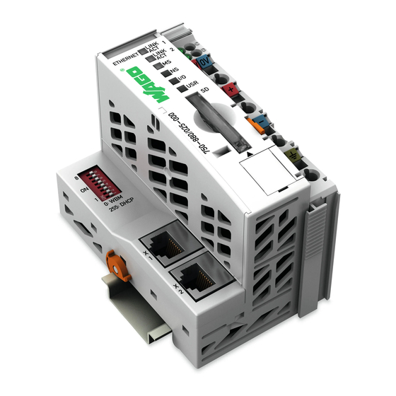
View PLC ETHERNET 750-880 and its Connection 3.1.2 Figure 1: View PLC ETHERNET 750-880 and its 24 V/0 V Connection Pos : 17 /D okumentation allgemei n/Glieder ungs elemente/---Seitenwec hs el--- @ 3\mod_1221108045078_0.doc @ 21810 @ @ 1 Quickstart Reference... -
Page 15: Table 4: Legend To The View Ethernet Tcp/Ip Fieldbus Controller
750-880, -881, -882 ETHERNET Programmable Fieldbus Pos : 18 /Serie 750 ( WAGO-I/O-SYST EM)/Ger ätebesc hrei bung/Ansic ht/Fel dbus koppl er/-contr oller/Leg ende/Ansic ht - Legende z ur Ansicht SETH ERNET (750- 880,881,882) - Tabellenkopf und Nr: 1 @ 7\mod_1266415064861_21.doc @ 50950 @ @ 1... -
Page 16: View Plc Ethernet 750-881 And Its Connection
750-880, -881, -882 ETHERNET Programmable Fieldbus Pos : 25 /Serie 750 ( WAGO-I/O-SYST EM)/Ger ätebesc hrei bung/Ansic ht/Fel dbus koppl er/-contr oller/Bilder/Ansic ht und bs p. Ansc hlus s - Bild 750- 0881 @ 9\mod_1287578134081_21.doc @ 65764 @ 3 @ 1 View PLC ETHERNET 750-881 and its Connection 3.1.3... -
Page 17: Table 5: Legend To The View Ethernet Tcp/Ip Fieldbus Controller
750-880, -881, -882 ETHERNET Programmable Fieldbus Pos : 27 /Serie 750 ( WAGO-I/O-SYST EM)/Ger ätebesc hrei bung/Ansic ht/Fel dbus koppl er/-contr oller/Leg ende/Ansic ht - Legende z ur Ansicht SETH ERNET (750- 880,881,882) - Tabellenkopf und Nr: 1 @ 7\mod_1266415064861_21.doc @ 50950 @ @ 1... -
Page 18: View Plc Ethernet 750-882 And Its Connection
750-880, -881, -882 ETHERNET Programmable Fieldbus Pos : 33 /Serie 750 ( WAGO-I/O-SYST EM)/Ger ätebesc hrei bung/Ansic ht/Fel dbus koppl er/-contr oller/Bilder/Ansic ht und bs p. Ansc hlus s - Bild 750- 0882 @ 11\mod_1317980134568_21.doc @ 80922 @ 3 @ 1 View PLC ETHERNET 750-882 and its Connection 3.1.4... -
Page 19: Table 6: Legend To The View Ethernet Tcp/Ip Fieldbus Controller
750-880, -881, -882 ETHERNET Programmable Fieldbus Pos : 35 /Serie 750 ( WAGO-I/O-SYST EM)/Ger ätebesc hrei bung/Ansic ht/Fel dbus koppl er/-contr oller/Leg ende/Ansic ht - Legende z ur Ansicht SETH ERNET (750- 880,881,882) - Tabellenkopf und Nr: 1 @ 7\mod_1266415064861_21.doc @ 50950 @ @ 1... -
Page 20: Operating Mode Switch
Pos : 42 /Serie 750 ( WAGO-I/O-SYST EM)/Ger ätebesc hrei bung/Ei nlei tung/Fel dbus koppl er/-c ontroller/Einl eitender Text/Quic kstart 750-088x: Hi nweis: Betriebsartensc hal ter i n die ober e Stellung schalten! @ 9\mod_1287492632163_21.doc @ 65716 @ @ 1... -
Page 21: Preparatory Measures
Preparatory Measures Pos : 45 /All e Seri en ( Allgemei ne Module)/Ü bers chriften für alle Serien/Inbetri ebnehmen - Konfigurier en - Parametrier en/WAGO-I/O-PR O i nstallieren - Ü berschrift 3 @ 13\mod_1348225656942_21.doc @ 103166 @ 3 @ 1 3.2.1... -
Page 22: Figure 6: Selecting The Setup Language
Quickstart Description WAGO-I/O-SYSTEM 750 750-880, -881, -882 ETHERNET Programmable Fieldbus Select the language and confirm it by clicking the button [OK]. Figure 6: Selecting the setup language Start the Setup using the InstallShield Wizard by clicking the button [Next >]. -
Page 23: Figure 7: License Agreement
WAGO-I/O-SYSTEM 750 Quickstart Description 750-880, -881, -882 ETHERNET Programmable Fieldbus Accept the license agreement by clicking the button [Yes]. Figure 7: License agreement Select the target directory and confirm it by clicking the button [Next]. Figure 8: Selecting the target directory Quickstart Reference Version 1.0.0... -
Page 24: Figure 9: Selection Of Components
Quickstart Description WAGO-I/O-SYSTEM 750 750-880, -881, -882 ETHERNET Programmable Fieldbus Select the components to be installed and confirm it by clicking the button [Next]. Figure 9: Selection of components Select the program folder and confirm it by clicking the button [Next]. -
Page 25: Figure 11: Overview Of Configuration
Check the settings you have defined and confirm it by clicking the button [Next]. Figure 11: Overview of configuration The pdf document „EA_ConfigurationReleaseInfo.pdf “with information about the new version of the WAGO-IO-Configuration dialogue is opened. Figure 12: pdf file „EA_ConfigurationReleaseInfo.pdf“ Quickstart Reference Version 1.0.0... -
Page 26: Starting Up The Ehernet Network
Quickstart Description WAGO-I/O-SYSTEM 750 750-880, -881, -882 ETHERNET Programmable Fieldbus Complete the CoDeSys setup by clicking the button [Finish]. Figure 13: Completing the setup 3.2.2 Starting Up the Ehernet Network This section provides you with a step-by-step sample procedure for starting up the ETHERNET network. -
Page 27: Figure 14: Properties Of Your Lan Network Link
WAGO-I/O-SYSTEM 750 Quickstart Description 750-880, -881, -882 ETHERNET Programmable Fieldbus 3.2.2.1 Determining the IP address of your PC and changing it if required The explanation below describes how you can determine the IP address currently set for your PC and how you can change it if required. -
Page 28: Assigning An Ip Address To The Sps
SPS. The option using the address selection switch is described in this QuickStart Guide. The other options are not described here, as these are explained separately in the respective manuals for the „750-880 ETHERNET Programmable Fieldbus Quickstart Reference Version 1.0.0... -
Page 29: Table 8: Ip Address Structure
WAGO-I/O-SYSTEM 750 Quickstart Description 750-880, -881, -882 ETHERNET Programmable Fieldbus Controller“, „750-881 ETHERNET Programmable Fieldbus Controller“ and „750-882 ETHERNET Programmable Media-Redundancy Fieldbus Controller“. Use the address selection switch to set the host ID, i.e., the last byte of the IP address, binary encoded in the range between 1 and 254. -
Page 30: Figure 16: Address Selection Switch With Set Ip Address (192.168.1.100)
Quickstart Description WAGO-I/O-SYSTEM 750 750-880, -881, -882 ETHERNET Programmable Fieldbus Set the bits in order using the 8 DIP switches. Begin with DIP switch 1 to set Bit 0 (LSB) and continue up to DIP switch 8 for Bit 7 (MSB). -
Page 31: Testing The Ethernet Link
WAGO-I/O-SYSTEM 750 Quickstart Description 750-880, -881, -882 ETHERNET Programmable Fieldbus 3.2.2.3 Testing the ETHERNET Link To test the ETHERNET link open the command line interpreter by entering "cmd" at Start > Execute… under Windows. Figure 18: "Execute .." dialog window Enter the command "ping 192.168.1.100."... -
Page 32: Installing The Usb Driver
WAGO-I/O-SYSTEM 750 750-880, -881, -882 ETHERNET Programmable Fieldbus 3.2.3 Installing the USB Driver The "WAGO USB Service Cable" (Item No.: 750-923) provides easy communication with the WAGO software tools (WAGO-ETHERNET-Settings, WAGO-I/O-CHECK 3, etc.) and with the IEC-61131 programming topology (WAGO-I/O-PRO). -
Page 33: Figure 22: Selecting The Target Directory
WAGO-I/O-SYSTEM 750 Quickstart Description 750-880, -881, -882 ETHERNET Programmable Fieldbus Select the installation directory and start the setup by clicking the button [Install]. Figure 22: Selecting the target directory As soon as tThe installation completed successfully, finish the Setup by clicking the button [OK]. -
Page 34: The First Program
The First Program Pos : 49 /Serie 750 ( WAGO-I/O-SYST EM)/Ger ätebesc hrei bung/Ei nlei tung/Fel dbus koppl er/-c ontroller/Einl eitender Text/Quic kstart 750-088x: Besc hreibung - Teil 2 @ 11\mod_1318404533600_21.doc @ 81133 @ 3333334433442 @ 1 Preparatory measures are required! Please note that the steps described below require that the preparatory measures cited previously have all been successfully performed. -
Page 35: Figure 25: Confirm Target System Settings (Example: Wago_750-881)
WAGO-I/O-SYSTEM 750 Quickstart Description 750-880, -881, -882 ETHERNET Programmable Fieldbus Click [OK] to confirm your target system settings. Figure 25: Confirm target system settings (example: WAGO_750-881) The "New Module" dialog appears. If you want to change the target system of your project later, select the Target System Settings on the Resources tab. -
Page 36: Create Plc_Prg Module
Quickstart Description WAGO-I/O-SYSTEM 750 750-880, -881, -882 ETHERNET Programmable Fieldbus 3.3.3 Create PLC_PRG Module If you want to create an initial module in a new project, the module automatically receives the name "PLC_PRG". Execution starts from there and you can also call other modules from there (programs, function blocks, and functions). -
Page 37: Figure 28: Configure The Hardware Under: Resources Tab, Plc Configuration
WAGO-I/O-SYSTEM 750 Quickstart Description 750-880, -881, -882 ETHERNET Programmable Fieldbus For the hardware configuration, double-click PLC Configuration on the Resources tab. Figure 28: Configure the hardware under: Resources tab, PLC Configuration The "PLC Configuration" dialog appears. In the "PLC Configuration" dialog, select K-Bus[FIX] in the tree structure. -
Page 38: Figure 30: "Configuration" Dialog Inputs/Outputs, Button [+]
Quickstart Description WAGO-I/O-SYSTEM 750 750-880, -881, -882 ETHERNET Programmable Fieldbus Click on the [+] button in the "I/O Configurator" dialog. The "Selected Modules" dialog appears. Figure 30: "Configuration" dialog Inputs/Outputs, button [+] In the left window, select the I/O modules based on your hardware setup and click on the [Insert >>] button to add them. -
Page 39: Figure 32: "Configuration" Dialog, Inputs/Outputs Tab, Assign Global Variables
WAGO-I/O-SYSTEM 750 Quickstart Description 750-880, -881, -882 ETHERNET Programmable Fieldbus The end module is not specified! Please note that the 750-600 end module is not specified when configuring the PLC. Click [OK] to close the "Selected Modules" dialog. Then assign variables to the digital input/output modules in the right window of the I/O Configurator. -
Page 40: Table 10: Digital Input Module 750-400
Quickstart Description WAGO-I/O-SYSTEM 750 750-880, -881, -882 ETHERNET Programmable Fieldbus Make the following declarations in this sample project: Table 10: Digital input module 750-400 Channel Variable DI 1 Table 11: Digital output module 750-501 Channel Variable Global variable declaration! Please note that the variables declared in the I/O configurator are known as global variables throughout the project. -
Page 41: Write Application
WAGO-I/O-SYSTEM 750 Quickstart Description 750-880, -881, -882 ETHERNET Programmable Fieldbus 3.3.5 Write Application In the sample project, the application consists of a simple control of the first channel (DO1) of the digital output module. It is controlled depending on the states of both channels (DI1 and DI2) of the digital input module. -
Page 42: Figure 35: Input Assistant, Select Standard Function Blocks
Quickstart Description WAGO-I/O-SYSTEM 750 750-880, -881, -882 ETHERNET Programmable Fieldbus Replace it with the required module by pressing <F2> to open the Input Assistant. A dialog appears in which you can select the required module from the available modules. Figure 35: Input Assistant, select standard function blocks... -
Page 43: Figure 36: Variable Declaration Dialog
WAGO-I/O-SYSTEM 750 Quickstart Description 750-880, -881, -882 ETHERNET Programmable Fieldbus Select the three question marks ??? above the inserted module, write the instance name "rsDO1" instead, and left-click behind the function block. The Variable Declaration dialog appears in which the VAR class (for local variables), name rsDO1, and type RS are already entered. -
Page 44: Figure 37: Global Variables
Quickstart Description WAGO-I/O-SYSTEM 750 750-880, -881, -882 ETHERNET Programmable Fieldbus Select the three question marks ??? located on the inserted SET block input. Press <F2> to open the Input Assistant. The Input Assistant appears. In the left window, select the Global Variable category, and in the right window, the D1 (BOOL) variable. -
Page 45: Figure 38: Function Block Assignment
WAGO-I/O-SYSTEM 750 Quickstart Description 750-880, -881, -882 ETHERNET Programmable Fieldbus Select the three question marks ??? located on the inserted RESET1 block input. Press <F2> to open the Input Assistant. The Input Assistant appears. In the left window, select the Global Variable category, and in the right window, the D2 (BOOL) variable. -
Page 46: Figure 39: Function Block Assignment Do1
Quickstart Description WAGO-I/O-SYSTEM 750 750-880, -881, -882 ETHERNET Programmable Fieldbus Now select the Assignment menu item and assign the global variable DO1 (BOOL) in the same way to the output of the function block. Figure 39: Function block assignment DO1 Quickstart Reference Version 1.0.0... -
Page 47: Commissioning
750-880, -881, -882 ETHERNET Programmable Fieldbus 3.3.6 Commissioning This chapter describes step-by-step how to load your previously created WAGO I/O-PRO project into your PLC, how to start program execution, and how to create a boot project. 3.3.6.1 Configuring a Communication Driver for an ETHERNET Link To set up the communication driver for the ETHERNET connection, click on the Communication Parameters... -
Page 48: Figure 41: Communication Parameters, Create Communication Channel
Quickstart Description WAGO-I/O-SYSTEM 750 750-880, -881, -882 ETHERNET Programmable Fieldbus In the "Communication Parameters" dialog, click the [NEW…] button to create a new communication channel. The "Communication Parameters: New Channel" dialog appears. Figure 41: Communication Parameters, Create communication channel For an ETHERNET connection, assign a name to the communication channel you just created in the Name input box (here "ETHERNETConnection"... -
Page 49: Configuring A Communication Driver For A Usb Link
WAGO-I/O-SYSTEM 750 Quickstart Description 750-880, -881, -882 ETHERNET Programmable Fieldbus Click [OK] to confirm your entries. Figure 43: Communication Parameters, IP address 3.3.6.2 Configuring a Communication Driver for a USB Link Connect the USB cable (750-923) to a USB port of your PC. -
Page 50: Figure 44: Wago Usb Service Cable (Comx)
750-880, -881, -882 ETHERNET Programmable Fieldbus Add the group Ports (COM and LPT) to the tree structure. The entry WAGO USB Service Cable (COMX) (the designation in parentheses indicates the assigned COM port; in this example COM27) is given within this group. -
Page 51: Figure 46: Communication Parameters, Com Port
WAGO-I/O-SYSTEM 750 Quickstart Description 750-880, -881, -882 ETHERNET Programmable Fieldbus Then select the driver "Serial (RS-232) 3S Serial RS-232 driver". Click [OK] to confirm your entries. Then double-click on the COM1 address field in the Value column in the "Communication Parameters" dialog for this communication channel, so that it is marked in gray. -
Page 52: Loading And Starting The Program
(here DO2) via a button in the visualization. After you have loaded, and started the program created with the WAGO-I/O-PRO software, you can then display and operate the process via the visualization in two ways: •... -
Page 53: Create Visualization
Please note that the first program must be successfully created as previously described as a requirement for the steps below. It is imperative that you have created a WAGO-I/O-PRO project, selected a target system, created a PLC configuration with the I/O Configurator, created the described application in the PLC_PRG module, and configured a corresponding communication driver. -
Page 54: Figure 49: Visualization Element, Configure
The name of the visualization object must be "PLC_VISU"! Please note that the name of the visualization object must be "PLC_VISU" when creating a Web visualization. For a WAGO-I/O-PRO project with several visualization objects, the visualization object called "PLC_VISU" is always loaded first in the Internet browser. -
Page 55: Figure 50: Visualization Element Di1
WAGO-I/O-SYSTEM 750 Quickstart Description 750-880, -881, -882 ETHERNET Programmable Fieldbus In the "Configure element (#0)" dialog, select the Text category in the left drop-down list and assign the label "DI1" to this visualization element. Figure 50: Visualization element DI1 Then select the category Colors. -
Page 56: Figure 52: "Color" Dialog, Select Dark Green
Quickstart Description WAGO-I/O-SYSTEM 750 750-880, -881, -882 ETHERNET Programmable Fieldbus Select dark green in the "Color" dialog. Figure 52: "Color" dialog, select dark green Click [OK] to confirm your selection. In the Alarm color area on the right side, then click the [Inside] button to display the color selection. -
Page 57: Figure 54: "Color" Dialog, Select Bright Green
WAGO-I/O-SYSTEM 750 Quickstart Description 750-880, -881, -882 ETHERNET Programmable Fieldbus Select bright green in the "Color" dialog. Figure 54: "Color" dialog, select bright green Click [OK] to confirm your selection. In the "Configure element (#0)" dialog, select the Variables category in the left drop-down list. -
Page 58: Figure 56: Input Assistant, Select Global Variables
Quickstart Description WAGO-I/O-SYSTEM 750 750-880, -881, -882 ETHERNET Programmable Fieldbus In the right window, select the DI1 (BOOL) variable. Click [OK] to close the dialog. The DI1 variable is now entered in the Change color field. Figure 56: Input Assistant, select global variables Then click [OK] to close the "Configure element (#0) dialog. -
Page 59: Figure 58: Draw Three More Visualization Elements
WAGO-I/O-SYSTEM 750 Quickstart Description 750-880, -881, -882 ETHERNET Programmable Fieldbus Draw three more circles using the "Ellipse" visualization element, just as was described for the first circle. Figure 58: Draw three more visualization elements Then configure the visualization elements as follows:... -
Page 60: Figure 59: Configured Visualization Elements
Quickstart Description WAGO-I/O-SYSTEM 750 750-880, -881, -882 ETHERNET Programmable Fieldbus Table 14: Visualization element 4 - configuration settings Category: Range Value Text Content (text) Colors Color (inside) Dark green: Colors Alarm color (inside) Light green: Variables Variables (Change color) Input... -
Page 61: Figure 60: Program Running On The Plc
WAGO-I/O-SYSTEM 750 Quickstart Description 750-880, -881, -882 ETHERNET Programmable Fieldbus Figure 60: Program running on the PLC Quickstart Reference Version 1.0.0... -
Page 62: Web Visualization
Log out to make changes to the target system settings! Please note that you have to log out of the WAGO-I/O-PRO software to make changes to the target system settings. If you are still logged in on your PLC with the WAGO-I/O-PRO software, then click on the Logout menu item in the WAGO-I/O-PRO dialog under the Online menu. -
Page 63: Figure 62: "Target System Settings" Dialog, Activate Web Visualization
Figure 62: "Target System Settings" dialog, Activate web visualization Click [OK] to confirm your selection. The "Target System Settings" dialog closes. Click the Clean all menu item in the WAGO-I/O-PRO dialog under the Project menu. Then click the Translate all menu item in Project menu. -
Page 64: Memory Card (750-880) For Memory Expansion
Figure 63: HTML page "WebVisu" Memory Card (750-880) for Memory Expansion The PLC ETHERNET 750-880 has the option of using a memory card to expand the memory. The memory card is optional and serves as additional memory for the internal memory of the PLC ETHERNET 750-880. -
Page 65: Memory Card Slot
750-880, -881, -882 ETHERNET Programmable Fieldbus Pos : 51 /Serie 750 ( WAGO-I/O-SYST EM)/Ger ätebesc hrei bung/Bedienel emente/F el dbus koppl er/-contr oller/Speicher karten-Stec kpl atz - Übersc hrift 3 und Besc hreibung @ 9\mod_1286366340882_21.doc @ 65430 @ 344 @ 1 3.4.1... -
Page 66: Inserting A Memory Card
Quickstart Description WAGO-I/O-SYSTEM 750 750-880, -881, -882 ETHERNET Programmable Fieldbus 3.4.1.1 Inserting a Memory Card Use an activation tool or a screwdriver to open the transparent cover flap by folding it upwards. Hold the memory card so that the contacts are visible on the left side and the sloping edge is towards the bottom, as depicted in the figure above. -
Page 67: Access To The Sd Card Via Ftp Client
750-880, -881, -882 ETHERNET Programmable Fieldbus Pos : 53 /Serie 750 ( WAGO-I/O-SYST EM)/Ger ätebesc hrei bung/Ei nlei tung/Fel dbus koppl er/-c ontroller/Einl eitender Text/Quic kstart 750-088x: Besc hreibung - Teil 3 @ 11\mod_1321439526108_21.doc @ 83220 @ 31 @ 1 3.4.2... -
Page 68: Figure 66: "Filezilla" Ftp Client, Server Manager - "Advanced" Tab
Quickstart Description WAGO-I/O-SYSTEM 750 750-880, -881, -882 ETHERNET Programmable Fieldbus Then configure the new server on the "Advanced" tab as follows. Enter "s:\" as the default directory on the server. Figure 66: "FileZilla" FTP client, Server Manager - "Advanced" tab Then configure the new server on the "Transfer Settings"... -
Page 69: Table 15: Fieldbus Protocols Supported By The Plc
WAGO-I/O-SYSTEM 750 Fieldbus Protocols Supported 750-880, -881, -882 ETHERNET Programmable Fieldbus Then click the [Connect] button to establish a connection to the SD card and to carry out the required access to the SD card. Fieldbus Protocols Supported Table 15: Fieldbus protocols supported by the PLC... - Page 70 Pos : 55 /D okumentation allgemei n/Verz eic hniss e/Abbil dungs verz eic hnis - ohne Gliederung - und Verz eichnis @ 3\mod_1219222916765_21.doc @ 21080 @ @ 1 List of Figures Figure 1: View PLC ETHERNET 750-880 and its 24 V/0 V Connection .... 14 Figure 2: View PLC ETHERNET 750-881 and its 24 V/0 V Connection .... 16 Figure 3: View PLC ETHERNET 750-882 and its 24 V/0 V Connection ....
- Page 71 WAGO-I/O-SYSTEM 750 List of Figures 750-880, -881, -882 ETHERNET Programmable Fieldbus Figure 48: Create visualization ................53 Figure 49: Visualization Element, Configure... context menu item ..... 54 Figure 50: Visualization element DI1 ..............55 Figure 51: Color category, Color area, open "Color" dialog ......... 55 Figure 52: "Color"...
- Page 72 List of Tables WAGO-I/O-SYSTEM 750 750-880, -881, -882 ETHERNET Programmable Fieldbus Pos : 57 /D okumentation allgemei n/Verz eic hniss e/T abell enverz eichnis - ohne Glieder ung - und Verzeic hnis @ 3\mod_1219222958703_21.doc @ 21084 @ @ 1 List of Tables Table 1: Number Notation ..................
- Page 73 WAGO-I/O-SYSTEM 750 750-880, -881, -882 ETHERNET Programmable Fieldbus Pos : 59 /D okumentation allgemei n/Einband/Einband H andbuc h - Leers eite für ger ade Sei tenz ahl @ 3\mod_1219230851078_0.doc @ 21123 @ @ 1 Quickstart Reference Version 1.0.0...
- Page 74 Pos : 60 /D okumentation allgemei n/Einband/Einband H andbuc h - R üc kseite @ 9\mod_1285229376516_21.doc @ 64944 @ @ 1 WAGO Kontakttechnik GmbH & Co. KG Postfach 2880 • D-32385 Minden Hansastraße 27 • D-32423 Minden Phone: +49/5 71/8 87 – 0 Fax: +49/5 71/8 87 –...
Need help?
Do you have a question about the 750-880 and is the answer not in the manual?
Questions and answers