
Subscribe to Our Youtube Channel
Related Manuals for WAGO 750-830


Summary of Contents for WAGO 750-830
- Page 1 Modular I/O System BACnet/IP Controller 750-830 Manual Technical description, installation and configuration Version 1.0.1...
- Page 2 2 • General Copyright © 2008 by WAGO Kontakttechnik GmbH & Co. KG All rights reserved. The contents of this documentation are taken in part from the BACnet Stan- dard 135-2004 or are based on the original contents. These contents are sub- ject to copyright.
-
Page 3: Table Of Contents
Safety Information.................. 10 Font Conventions ................... 11 Number Notation ..................11 Scope ...................... 12 Abbreviation................... 12 2 The WAGO-I/O-SYSTEM 750 ..............13 System Description................. 13 Technical Data..................14 Manufacturing Number ................20 Component Update................. 21 Storage, Assembly and Transport ............21 Mechanical Setup ................... - Page 4 6.50 Notify_Type ..................295 6.51 Number_Of_APDU_Retries..............295 6.52 Object_Identifier .................. 296 6.53 Object_List ................... 296 6.54 Object_Name..................296 6.55 Object_Type ..................297 6.56 Out_Of_Service..................297 6.57 Polarity ....................298 6.58 Present_Value..................299 6.59 Priority_Array ..................302 WAGO-I/O-SYSTEM 750 BACnet/IP Controller...
- Page 5 Foreword ....................316 Protective Measures ................316 Classification Meeting CENELEC and IEC ........316 Classifications Meeting the NEC 500 ..........323 Identification ..................325 Installation Regulations................ 327 Glossary ......................331 Literature List ....................355 Index......................356 WAGO-I/O-SYSTEM 750 BACnet/IP Controller...
-
Page 6: Important Notes
WAGO Kontakttechnik GmbH & Co. KG, Minden. Non-observance will en- tail the right of claims for damages. WAGO Kontakttechnik GmbH & Co. KG reserves the right of changes serv- ing technical progress. All rights developing from the issue of a patent or the legal protection of util- ity patents are reserved to WAGO Kontakttechnik GmbH &... - Page 7 All personnel must be familiar with the applicable standards. WAGO Kontakttechnik GmbH & Co. KG declines any liability resulting from improper action and damage to WAGO products and third party products due to non-observance of the information contained in this manual.
-
Page 8: Standards And Regulations For Operating The 750 Series
(emissions of interference) according to EN 61000-6-3. You will find the relevant in- formation in the section on "WAGO-I/O-SYSTEM 750" ! "System De- scription" ! "Technical Data". • Please observe the safety measures against electrostatic discharge accord- ing to DIN EN 61340-5-1/-3. -
Page 9: Symbols
Note Make important notes that are to be complied with so that a trouble-free and efficient device operation can be guaranteed. Additional Information References to additional literature, manuals, data sheets and internet pages. WAGO-I/O-SYSTEM 750 BACnet/IP Controller... -
Page 10: Safety Information
Danger The WAGO-I/O-SYSTEM 750 and its components are an open system. It must only be assembled in housings, cabinets or in electrical operation rooms. Access is only permitted via a key or tool to authorized qualified per- sonnel. -
Page 11: Font Conventions
Only for use in LAN, not for connection to telecommunication circuits. 1.5 Font Conventions Names of paths and files are marked in italic. italic e.g.: C:\Programs\WAGO-IO-CHECK Menu items are marked in bold italic. italic e.g.: Save A backslash between two names characterizes the selection of a menu point from a menu. -
Page 12: Scope
12 • Important Notes Scope 1.7 Scope This manual describes the field bus independent WAGO I/O SYSTEM 750 with the programmable BACnet/IP Controller. Item.-No. Description 750-830 BACnet/IP Controller 1.8 Abbreviation Analog Input Analog Output Digital Input Digital Output Input/Output Identifier... -
Page 13: The Wago-I/O-System 750
The field bus coupler communicates via the relevant field bus. The program- mable field bus controller (PFC) enables the implementation of additional PLC functions. Programming is done with the WAGO I/O PRO CAA in ac- cordance with IEC 61131-3. Bus modules for diverse digital and analog I/O functions as well as special functions can be connected to the coupler/controller. -
Page 14: Technical Data
Maximum pollutant concentration at relative humidity < 75% S ≤ 10 ppm Special conditions Ensure that additional measures for components are taken, which are used in an environment involving: – dust, caustic vapors or gases – ionization radiation WAGO-I/O-SYSTEM 750 BACnet/IP Controller... - Page 15 150 kHz ... 500 kHz conducted) 30 dB (μA) 500 kHz ... 30 MHz EN 55022 (radiated) 30 dB (μV/m) 30 MHz ... 230 MHz 10 m 37 dB (μV/m) 230 MHz ... 1 GHz 10 m WAGO-I/O-SYSTEM 750 BACnet/IP Controller...
- Page 16 IEC 60068-2-32 free fall (module in original packing) *) QP: Quasi Peak Note If the technical data of components differ from the values described here, the technical data shown in the manuals of the respective components shall be valid. WAGO-I/O-SYSTEM 750 BACnet/IP Controller...
- Page 17 Technical Data • 17 Technical Condition of the Devices For Products of the WAGO-I/O-SYSTEM 750 with ship specific approvals supplementary guidelines are valid: Electromagnetic compatibility Immunity to interference acc. to Germanischer Lloyd (2003) Test specification Test values Strength Evaluation class...
- Page 18 Germany, the Federal Office for Post and Telecommunications and its branch offices issues the permit. It is possible to use other field bus couplers/controllers under certain boundary condi- tions. Please contact WAGO Kontakttechnik GmbH & Co. KG. Maximum power dissipation of the components Bus modules 0.8 W / bus terminal (total power dissipation, sys-...
- Page 19 Technical Condition of the Devices Dimensions 01 02 24V 0V Side view Dimensions in mm Fig. 2-2: Dimensions g01xx05e Note The illustration shows a standard coupler. For detailed dimensions, please refer to the technical data of the respective coupler/controller. WAGO-I/O-SYSTEM 750 BACnet/IP Controller...
-
Page 20: Manufacturing Number
The manufacturing number consists of the production week and year, the soft- ware version (if available), the hardware version of the component, the firm- ware loader (if available) and further internal information for WAGO Kontakttechnik GmbH & Co. KG. WAGO-I/O-SYSTEM 750 BACnet/IP Controller... -
Page 21: Component Update
Thereby, the ESD information is to be regarded. Statically shielded transport bags with metal coatings are to be used for the transport of open components for which soiling with amine, amide and sili- cone has been ruled out, e.g. 3M 1900E. WAGO-I/O-SYSTEM 750 BACnet/IP Controller... -
Page 22: Mechanical Setup
Attention In the case of vertical assembly, an end stop has to be mounted as an addi- tional safeguard against slipping. WAGO item 249-116 End stop for DIN 35 rail, 6 mm wide WAGO item 249-117 End stop for DIN 35 rail, 10 mm wide 2.6.2 Total Expansion... - Page 23 WAGO Kontakttechnik GmbH & Co. KG supplies standardized carrier rails that are optimal for use with the I/O system. If other carrier rails are used, then a technical inspection and approval of the rail by WAGO Kontakttech- nik GmbH & Co. KG should take place.
- Page 24 24 • Mechanical Setup Spacing 2.6.3.2 WAGO DIN Rail WAGO carrier rails meet the electrical and mechanical requirements. Item Number Description 210-113 /-112 35 x 7.5; 1 mm; steel yellow chromated; slotted/unslotted 210-114 /-197 35 x 15; 1.5 mm; steel yellow chromated; slotted/unslotted 210-118 35 x 15;...
- Page 25 Fig. 2-6: removing bus terminal p0xxx01x Danger Ensure that an interruption of the PE will not result in a condition which could endanger a person or equipment! For planning the ring feeding of the ground wire, please see chapter 2.6.3. WAGO-I/O-SYSTEM 750 BACnet/IP Controller...
- Page 26 4-channel digital input module, has a decreased air and creepage distance to the neighboring contact in the example DI4. Always terminate the field bus node with an end module (750-600). WAGO-I/O-SYSTEM 750 BACnet/IP Controller...
- Page 27 The modules are equipped with electronic components that may be destroyed by electrostatic discharge. When handling the modules, ensure that the envi- ronment (persons, workplace and packing) is well grounded. Avoid touching conductive components, e.g. data contacts. WAGO-I/O-SYSTEM 750 BACnet/IP Controller...
- Page 28 Fig. 2-8: Example for the arrangement of power contacts g0xxx05e Recommendation With the WAGO ProServe® Software smartDESIGNER, the structure of a field bus node can be configured. The configuration can be tested via the in- tegrated accuracy check. WAGO-I/O-SYSTEM 750...
- Page 29 WAGO Terminal Blocks. The terminal blocks may be jumpered together and a single wire brought back to the I/O module connection point.
-
Page 30: Power Supply
When using a joint power supply unit for the 24 V system supply and the 24 V field supply, the electrical isolation between the internal bus and the field level is eliminated for the potential group. WAGO-I/O-SYSTEM 750 BACnet/IP Controller... - Page 31 2.7.2 System Supply 2.7.2.1 Connection The WAGO-I/O-SYSTEM 750 requires a 24 V direct current system supply (-15 % or +20 %). The power supply is provided via the coupler/controller and, if necessary, in addition via the internal system supply modules (750-613).
- Page 32 If the sum of the internal current consumption exceeds the residual current for bus modules, then an internal system supply module (750-613) must be placed before the module where the permissible residual current was ex- ceeded. WAGO-I/O-SYSTEM 750 BACnet/IP Controller...
- Page 33 (750-613), e.g. in the middle of the node, should be added. Recommendation With the WAGO ProServe® Software smartDESIGNER, the assembly of a field bus node can be configured. The configuration can be tested via the in- tegrated accuracy check.
- Page 34 By inserting an additional power supply module, the field supply via the power contacts is disrupted. From there a new power supply occurs which may also contain a new voltage potential. WAGO-I/O-SYSTEM 750 BACnet/IP Controller...
- Page 35 750-601 24 V DC, Supply/Fuse 750-609 230 V AC, Supply/Fuse 750-615 120 V AC, Supply/Fuse 750-610 24 V DC, Supply/Fuse/Diagnosis 750-611 230 V AC, Supply/Fuse/Diagnosis Fig. 2-14: Supply module with fuse carrier (Example 750-610) g0xxx09x WAGO-I/O-SYSTEM 750 BACnet/IP Controller...
- Page 36 Lifting the cover to the side opens the fuse carrier. Fig. 2-16: Opening the fuse carrier p0xxx03x Fig. 2-17: Change fuse p0xxx04x After changing the fuse, the fuse carrier is pushed back into its original posi- tion. WAGO-I/O-SYSTEM 750 BACnet/IP Controller...
- Page 37 Power Supply • 37 Field Supply Alternatively, fusing can be done externally. The fuse modules of the WAGO series 281 and 282 are suitable for this purpose. Fig. 2-18: Fuse modules for automotive fuses, series 282 pf66800x Abb. 2-19: Fuse modules for automotive fuses, series 2006 p0xxx13x Fig.
- Page 38 Supplementary Power Supply Regulations 2.7.4 Supplementary Power Supply Regulations The WAGO-I/O-SYSTEM 750 can also be used in shipbuilding or offshore and onshore areas of work (e. g. working platforms, loading plants). This is demonstrated by complying with the standards of influential classification companies such as Germanischer Lloyd and Lloyds Register.
- Page 39 2) Ring-feeding 10 A recommended a) Power Supply on coupler / controller via external Supply Module b) Internal System Supply Module c) Supply Module passive Supply Module with fuse carrier/ iagnostics Fig. 2-23: Supply example g0xxx04e WAGO-I/O-SYSTEM 750 BACnet/IP Controller...
- Page 40 Power Supply Power Supply Unit 2.7.6 Power Supply Unit The WAGO-I/O-SYSTEM 750 requires a 24 V direct current system supply with a maximum deviation of -15 % or +20 %. Recommendation A stable network supply cannot be taken for granted always and everywhere.
-
Page 41: Grounding
The optimal insulated setup is a metallic assembly plate with grounding con- nection with an electrical conductive link with the carrier rail. The separate grounding of the carrier rail can be easily set up with the aid of the WAGO ground wire terminals. Item No. Description... - Page 42 Attention Care must be taken to ensure the direct electrical connection between the carrier rail contact and the carrier rail. The carrier rail must be grounded. For information on carrier rail properties, please see chapter 2.6.3.2. WAGO-I/O-SYSTEM 750 BACnet/IP Controller...
- Page 43 Fig. 2-25: Ring-feeding g0xxx07e Attention The regulations relating to the place of assembly as well as the national regu- lations for maintenance and inspection of the grounding protection must be observed. WAGO-I/O-SYSTEM 750 BACnet/IP Controller...
-
Page 44: Shielding (Screening)
Note For a better shield performance, the shield should have previously been placed over a large area. The WAGO shield connection system is suggested for such an application. This suggestion is especially applicable if the equipment can have even cur- rent or high impulse formed currents running through (for example initiated by atmospheric discharge). -
Page 45: Assembly Guidelines/Standards
WAGO Shield (Screen) Connecting System 2.9.4 WAGO Shield (Screen) Connecting System The WAGO Shield Connecting system includes a shield clamping saddle, a collection of rails and a variety of mounting feet. Together these allow many different possibilities. See catalog W4 volume 3 chapter 10. -
Page 46: Fieldbus Controller
The RS232 interface can be used as a standard RS232 or (beginning with software version 2) as a BACnet-PTP connection to other PTP-capable BACnet devices. The 750-830 BACnet/IP Controller is based on an ETHERNET controller and supports the corresponding functions: All input signals from the sensors are combined. After connecting the control- ler, all of the I/O modules on the node are determined and a local process im- age is created from these. - Page 47 • 47 Compatibility An application program can be created using the WAGO-I/O-PRO CAA soft- ware, based on IEC 61131-3. The controller provides 512 KB of program memory, 256 KB of data memory and 24 KB of retain memory for this pur- pose.
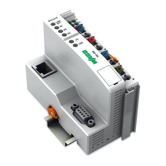
- Page 48 48 • BACnet/IP Controller 750-830 Hardware 3.1.3 Hardware 3.1.3.1 View BACnet/IP 01 02 power supply status LINK - system fieldbus - power contacts connection 24V 0V RJ45 data contacts bus coupler power supply power contacts supply fieldbus connection RS232 power contacts...
- Page 49 BACnet/IP Controller 750-830 • 49 Hardware 3.1.3.2 Power Supply ® The power supply is derived from modules with CAGE CLAMP connec- tions. 24 V power supply (see Fig. 3-1) for system power and power to the field side. The integrated power supply provides the required power to the electronics and the bus modules.
- Page 50 50 • BACnet/IP Controller 750-830 Hardware 3.1.3.3 Fieldbus Connection The connection to the fieldbus is made via an RJ45 connector, which is also called a "Western plug." Wiring for the RJ45 socket on the fieldbus controller adheres to 100BaseTX specifications. It is mandatory to use a twisted pair ca- ble of category 5 as a connecting cable.
- Page 51 (LEDs). These are multi-colored (red, green or red-green (=orange)). BACnet/IP 01 02 01 02 ETHERNET 24V 0V 24V 0V Fig. 3-2: Indicators 750-830 g083002x Tab. 3-3: LED Signals Color Meaning LNK/ACT Green Network connection and activity at Port 1...
- Page 52 BACnet/IP Controller 750-830 Hardware 3.1.3.5 Configuration Interface and Programming Interface The configuration interface is located behind the cover flap. It is used for communication with WAGO-I/O-CHECK, WAGO-I/O-PRO CAA and for downloading firmware. Configuration and programming interface Fig. 3-3: Configuration Interface g01xx07e The communication cable (750-920) is connected to the four-pole header.
- Page 53 BACnet/IP Controller 750-830 • 53 Hardware 3.1.3.6 Mode Selector Switch The mode selector switch is located behind the cover flap. STOP RESET (pushing down) UPDATE FIRMWARE Mode switch Fig. 3-4: Mode Selector Switch g01xx10e The switch is a push button or sliding switch with three positions and a push- button function.
- Page 54 The MAC ID has a set length of 6 bytes (48 bits) (hexadecimal). The first three bytes identify the manufacturer (e.g. 00:30 DE for WAGO). The second 3 bytes indicate the consecutive serial number for the hardware.
- Page 55 After successful boot-up, the PFC cycle starts if the mode selection switch is in the upper position or due to a start command from the WAGO-I/O-PRO CAA. The input and output data for the field bus, bus mod- ules and the timer values are read. Subsequently the PFC program in the RAM is processed;...
- Page 56 56 • BACnet/IP Controller 750-830 Operating System Switching on the supply voltage Is a PLC program in the Flash memory ? “I/O” LED is blinking orange PLC program transfer from the flash memory to RAM Determination of the I/O modules...
- Page 57 A node can consist of a mixed arrangement of analog and digital modules. Note Using the WAGO 750-628 Internal Data Bus Extension Coupler Module and 750-627 End Module makes it possible to connect up to 250 modules to the 830-830 BACnet/IP Controller.
- Page 58 The subsequent range, starting from word 1532, is reserved for future protocol expansion and other PFC variables. For all WAGO fieldbus controllers, access by the PLC (CPU) to process data is made regardless of the fieldbus system; access is always conducted through an application-related IEC 61131-3 program.
- Page 59 BACnet/IP Controller 750-830 • 59 Process Image 3.1.5.2 Example of an Input Process Image The following figure is an example of an input process image. The configuration comprises 16 digital and 8 analog inputs. The input process image thus has a data length of 8 words for the analog mod- ules and 1 word for the digital modules;...
- Page 60 60 • BACnet/IP Controller 750-830 Process Image 3.1.5.3 Example of an Output Data Process Image The following example for the output process image comprises 2 digital and 4 analog outputs. It comprises 4 words for the analog outputs and 1 word for the digital outputs, i.e.
- Page 61 Intel formats. The modules can be mapped directly via addresses with MODBUS. Additional Information For the fieldbus-specific structure of the process values of all bus modules within the 750 and 753 Series of the WAGO-I/O-SYSTEM, refer to section 3.1.5.4, "MODBUS Process Data". WAGO-I/O-SYSTEM 750 BACnet/IP Controller...
- Page 62 • 2 connections for WAGO-I/O-PRO CAA (these connections are reserved for downloading and debugging the application program via ETHERNET. WAGO-I/O-PRO CAA needs 2 connections at the same time for the de- bugging. However, only a programming tool can have access to the con- troller).
- Page 63 BACnet/IP Controller 750-830 • 63 Data Exchange 3.1.6.1 Memory Areas Programmable Fieldbus Controller memory area for input data word 0 input modules word 255 I/O modules word 256 MODBUS PFC - IN - variables word 511 word 512 input modules...
- Page 64 RAM memory. After error-free run-up, the PFC cycle starts with the mode selector switch at the top position, or on the Start command from the WAGO-I/O-PRO CAA. • NOVRAM remanent memory (24 kByte) The remanent memory is a non-transitory memory, i.e. all values are re- tained following a power failure.
- Page 65 (MODBUS). If you use MODBUS, take care that "fieldbus 1" is chosen in the WAGO-I/O- PRO CAA (see section 3.1.8.1). The WAGO I/O Configurator is also available as a further addressing op- tion.
- Page 66 66 • BACnet/IP Controller 750-830 Data Exchange 3.1.6.2.1 Addressing of Bus Modules Addressing first references complex modules (modules that occupy several bytes) in accordance with their physical order downstream of the fieldbus con- troller, i.e., they occupy addresses starting from word 0.
- Page 67 BACnet/IP Controller 750-830 • 67 Data Exchange 3.1.6.2.2 Example of Addressing Two digital input modules (2 DI), two digital output modules (2 DO) and two analog input modules (2 AI) and two analog output modules (2AO) are con- nected to one controller. The final element is an end module that is not taken into account for addressing.
- Page 68 68 • BACnet/IP Controller 750-830 Data Exchange 3.1.6.2.3 Address Ranges Subdivision of the address ranges for word-by-word addressing in accordance with IEC61131-3: Tab. 3-7: Breakdown of address range Word Data 0-255 Physical bus modules 256-511 MODBUS-PFC variables 512-1275 Other physical bus modules Word 0-255: First address range for the input/output data of the bus module: Tab.
- Page 69 BACnet/IP Controller 750-830 • 69 Data Exchange Word 512-1275: Second address range for the input/output data of the bus module: Tab. 3-10: Address range, word 512 - 1275 Data Address Width 512.0. 512.8... 513.0 .. 513.8..1274.0.. 1274.8.. 1275.0 ...
- Page 70 70 • BACnet/IP Controller 750-830 Data Exchange 3.1.6.2.4 Absolute Addressing Direct presentation of individual memory cells (absolute addresses) based on IEC 1131-3 is performed using character strings: Tab. 3-13: Absolute addresses Position Prefix Designation Commentary Introduces an absolute address Input...
- Page 71 BACnet/IP Controller 750-830 • 71 Data Exchange Calculating addresses (as a function of the word address): Bit address: Word address .0 to .15 Byte address: 1st byte: 2 x word 2nd byte: 2 x word address + 1 DWord address...
- Page 72 72 • BACnet/IP Controller 750-830 Data Exchange MODBUS master 0x0000 0x6000 0x0000 0x6000 (0x0200) (0x7000) 00x0FF 0x62FC 0x62FC 0x00FF (0x02FF) (0x72FC) Outputs Inputs I/O modules PII = Process Input Image PIO = Process Output Image Programmable Fieldbus Controller Fig. 3-9: Data exchange between MODBUS Master and bus modules g015045e Register functions start at address 0x1000.
- Page 73 BACnet/IP Controller 750-830 • 73 Data Exchange 3.1.6.4 Data Exchange between PLC Function (CPU) and Bus Modules The PLC function (CPU) of the PFC uses absolute addresses to access the bus module data directly. The PFC uses absolute addresses to reference the input data. The data can then be processed internally in the controller using the IEC 61131-3 program.
- Page 74 74 • BACnet/IP Controller 750-830 Data Exchange 3.1.6.5.1 Example of MODBUS/TCP Master and PLC Function (CPU) Data access by the MODBUS/TCP master Access to data by the MODBUS Master is always either by word or by bit. Addressing of the first 256 data words by the bus modules begins with word- by-word and bit-by-bit access at 0.
- Page 75 BACnet/IP Controller 750-830 • 75 Data Exchange 3.1.6.5.2 Juxtaposition of MODBUS/TCP and IEC 61131-3 Addresses 3.1.6.5.2.1 Word Access Tab. 3-15: Word access Method MODBUS Addresses IEC 61131 Addresses Description decimal hexadecimal 0... 0x0000 – %IW0... phys. inputs (1) - Read Multiple Register...
- Page 76 76 • BACnet/IP Controller 750-830 Data Exchange 3.1.6.5.2.2 Bit Access Tab. 3-16: Bit access Method MODBUS Addresses IEC 61131- Description Addresses decimal hexadecimal 0... 0x0000 – %IX( DigitalOffSet + 0 ).0 ... phys. inputs (1) - Read Input Discrete 0x01FF %IX( DigitalOffSet + 31).15...
- Page 77 BACnet/IP Controller 750-830 • 77 Data Exchange 3.1.6.5.2.3 Application Example Ethernet LINK TxD/RxD ERROR I/O Modules 750- 402 Bit 1 Bit 1 Bit 1 Word1 Word1 Word1 Process input image Word2 Word2 Bit 4 Bit 2 (Word) Addresses MODBUS Word1...
- Page 78 3.1.7.1 Startup Using the WAGO ETHERNET Settings "WAGO-ETHERNET Settings" (759-316) is a Windows application software that can be used to read and edit bus-specific parameters of WAGO- ETHERNET couplers/controllers. Communication cables or WAGO radio- link adapters can be used for data communication.
- Page 79 The following provides examples of fieldbus node IP address allocation using the "WAGO ETHERNET Settings" Program. Note The program "WAGO-ETHERNET Settings" is available for downloading at http://www.wago.com under: Downloads ! AUTOMATION. The program is also included on the CD "AUTOMATION Tools and Docs"...
- Page 80 80 • BACnet/IP Controller 750-830 Fieldbus Node Start-up 3.1.7.1.3 Testing for Proper Functioning of the Fieldbus Node 1. Set up a (non-serial) link between the client PC and the controller to test communication with the controller and correct assignment of the IP ad- dress.
- Page 81 BACnet/IP Controller 750-830 • 81 Fieldbus Node Start-up 3.1.7.2 Commissioning with the WAGO BootP Server An IP address and other parameters can be assigned to a coupler/controller in a TCP/IP network using the Bootstrap protocol (BootP). Subnet masks and gateways can also be transferred using this protocol.
- Page 82 82 • BACnet/IP Controller 750-830 Fieldbus Node Start-up 3.1.7.2.2 Connecting Client PC and Fieldbus Nodes 1. Connect the installed BACnet/IP controller to the client PC either directly, or using a 10BaseT or 100BaseTX cable via a hub. The controller transfer rate depends on the network data transfer rate of your client PC network card.
- Page 83 The controller must be assigned an IP address before it can communicate properly. This address can be assigned via "WAGO BootP server", or using a PFC pro- gram. When assigning an address using a PFC program, this can be done in WAGO-I/O-PRO CAA using the function block "Ethernet_Set_Network_Config"...
- Page 84 3.1.7.2.4.1 BootP Table The BootP table is the database for the BootP server. This table is available as a text file (bootptab.txt) on the client PC where the WAGO BootP server is in- stalled. Note The WAGO BootP server must be installed correctly before the following steps can be performed: 1.
- Page 85 BACnet/IP Controller 750-830 • 85 Fieldbus Node Start-up The examples shown contain the following information: Tab. 3-17: BootP Table Information Information Meaning node1, node2 Any name for a node can be specified here. ht=1 Here the hardware type of the network is specified.
- Page 86 9. Close the editor. 3.1.7.2.4.2 BootP Server 1. On your PC, go to Start and select the menu item Programs \ WAGO Software \ WAGO BootP Server. 2. Click on WAGO BootP server to open the dialog window. 3. Click on Start in the dialog window that then appears. This activates the query/response mechanism of the BootP protocol.
- Page 87 BACnet/IP Controller 750-830 • 87 Fieldbus Node Start-up 3.1.7.2.5 Testing the Function of the Fieldbus Node 1. In order to check communication with the controller and for correct IP ad- dress assignment, start the DOS prompt via Start / Programs / Command prompt.
- Page 88 88 • BACnet/IP Controller 750-830 Fieldbus Node Start-up 3.1.7.2.6 Deactivating the BootP Protocol By default, the BootP protocol is activated in the controller. When the BootP protocol is activated, the controller expects the BootP server to be perma- nently available. If there is no BootP server available after a PowerOn reset, the network will remain inactive.
- Page 89 BACnet/IP Controller 750-830 • 89 Fieldbus Node Start-up Fig. 3-2: HTML pages of the Web-based management system G083050e Note If these pages are not displayed for local access to the fieldbus nodes, you must define in the Web browser properties that, as an exception, no proxy server is to be used for the node IP address.
- Page 90 MODBUS functions using the MODBUS master too, such as querying of the module configuration via register 0x2030. If you have activated the WAGO-I/O-PRO for example, you can also program the controller via ETHERNET link using WAGO-I/O-PRO CAA in line with Standard IEC 61131-3.
- Page 91 "WAGO-I/O-PRO CAA". This manual is located at http://www.wago.com under: Documentation ! WAGO-I/O-SYSTEM759 ! WAGO-I/O-PRO ! 759-333 1. Start the programming tool at Start \ Programs \ WAGO-I/O-PRO and WAGO-I/O-PRO CAA. A dialog window then appears on which you can set the target system for pro- gramming.
- Page 92 The I/O Configurator is a plug-in incorporated into WAGO-I/O-PRO CAA for determining addresses for modules at a controller. 1. In the left half of the screen for the WAGO-I/O-PRO-CAA interface, select the tab Resources. 2. In the tree structure click PLC configuration. The I/O Configurator then starts up.
- Page 93 BACnet/IP Controller 750-830 • 93 Programming the PFC Using WAGO-I/O-PRO CAA Note The number of modules that send or receive data must correspond to the existing hardware (except for supply modules, copying modules or end mod- ules, for example). The number of input and output bits or bytes of the indi- vidually connected bus modules can be found in the corresponding descrip- tions of the bus modules.
- Page 94 If you wish to perform module assignment directly using the "EA- config.xml" file stored in the controller, do not save any configuration data in WAGO-I/O-PRO CAA prior to this, as the file is overwritten by entries in the WAGO-I/O-PRO CAA on each download.
- Page 95 You can then begin with IEC 61131-3 programming. Additional Information For a detailed description of how to use the software, please refer to the WAGO-I/O-PRO CAA manual. The manual available at http://www.wago.com under Documentation ! WAGO-I/O-SYSTEM 759 ! WAGO-I/O-PRO ! 759-333...
- Page 96 The SYM_XML file is a file that contains all project variables. This file is necessary for the BACnet Configurator. Proceed as follows to create this file: 1. In the WAGO-I/O-PRO CAA software under Project \ Options select the category Symbol configuration.
- Page 97 Programming the PFC Using WAGO-I/O-PRO CAA 3.1.8.3 ETHERNET Libraries for WAGO-I/O-PRO CAA Various libraries are available in WAGO-I/O-PRO CAA for different IEC 61131-3 programming tasks. These contain modules for universal use and can, thereby, facilitate and speed up the creation of your program.
- Page 98 For a detailed description of the function blocks and use of the software, refer to the WAGO-I/O-PRO CAA manual at http://www.wago.com under: Docu- mentation ! WAGO-I/O-SYSTEM 759 ! WAGO-I/O-PRO ! 759-333 or the online Help function for WAGO-I/O-PRO CAA. WAGO-I/O-SYSTEM 750 BACnet/IP Controller...
- Page 99 BACnet/IP Controller 750-830 • 99 Programming the PFC Using WAGO-I/O-PRO CAA 3.1.8.4 General Information about IEC Tasks Note Please note the following information when programming your IEC tasks. • IEC tasks must have different priorities, as otherwise an error will occur during translating of the application program.
- Page 100 100 • BACnet/IP Controller 750-830 Programming the PFC Using WAGO-I/O-PRO CAA 3.1.8.4.1 IEC Task Sequence 1. Determine the system time (tStart). 2. If no full internal bus cycle has run since the last time the outputs were written: ! Wait until the next internal bus cycle is completed.
- Page 101 Definition: Processes with the highest priority are identified by the lowest numbers. These processes are handled by all other processes. Additional Information For a detailed description of the programming tool WAGO-I/O-PRO CAA refer to the manual WAGO-I/O-PRO CAA at http://www.wago.com...
- Page 102 Possible events, for example: . Stop, Start, Online change. A complete list of all system events is provided at WAGO-I/O-PRO CAA / "Resources" tab" / "Task configuration" / "System events".
- Page 103 3.1.8.6.1 Transfer via Serial Service Port Use the WAGO communication cable to set up a physical connection via se- rial service port. This is included in the scope of supply for the programming software WAGO-I/O-PRO CAA (Item No.: 759-333) or can be procured as an accessory item under order no.
- Page 104 6. Under Online, click the menu item Login to log in to the controller. (The WAGO-I/O-PRO CAA Server is active during online operation. The communication parameters cannot be called up during this time.) If there is no program in the controller, a window appears asking whether or not the program is to be loaded.
- Page 105 The physical link between the PC and the controller is set up via fieldbus. An appropriate communication driver is required for data transfer. The driver and its parameters must be entered in the WAGO-I/O-PRO CAA in the dialog window "Communication parameters".
- Page 106 106 • BACnet/IP Controller 750-830 Programming the PFC Using WAGO-I/O-PRO CAA 3.1.8.7 The Web-Based Management System (WBMS) HTML pages containing information and setting options are stored in the con- troller as referred to as the Web-based management system. Use the menu on the left to navigate through these pages.
- Page 107 BACnet/IP Controller 750-830 • 107 Programming the PFC Using WAGO-I/O-PRO CAA ETHERNET Over the "Ethernet" link, you will reach a website on which you can configure the bandwidth limit and transmission rate for ETHERNET communication. With the BACnet/IP Controller, you will use Port 1 while setting the transmis- sion rate ("Speed Configuration") (see Tab.
- Page 108 108 • BACnet/IP Controller 750-830 Programming the PFC Using WAGO-I/O-PRO CAA A set data transfer rate can be defined for the set mode with the option field "Input/Output Limit Rate." For this, port 3 is the internal ETHERNET port linked to the CPU. Bandwidth limiting configured for Port 3 will not have an effect on the data transfer of ETHERNET Port 1!.
- Page 109 BACnet/IP Controller 750-830 • 109 Programming the PFC Using WAGO-I/O-PRO CAA TCP/IP Click the link "TCP/IP" to go to a Web site where you can specify the settings for the TCP/IP protocol. This protocol forms the basis for network data trans- fer.
- Page 110 Port Click the "Port" link to go to the "Port configuration" page, where you can ac- tivate or deactivate the desired protocol. Normally, FTP, HTTP, MODBUS/UDP, MODBUS/TCP, WAGO Services, and CoDeSys are activated. Fig. 3-11: Web-based Management System: Port WAGO-I/O-SYSTEM 750...
- Page 111 BACnet/IP Controller 750-830 • 111 Programming the PFC Using WAGO-I/O-PRO CAA SNMP Click the link "SNMP" to go to a Web site where you can specify the settings for the simple network management protocol. This protocol forms the basis for transfer of control data.
- Page 112 "WAGO-I/O-Check" program again. Note You can also use a WAGO-RTC module 750-640 at your node to utilize the actual time (encoded) in your higher-order control system. An even greater degree of accuracy is achieved using this "Real-Time Clock" module than that obtained using the real-time clock in the controller.
- Page 113 BACnet/IP Controller 750-830 • 113 Programming the PFC Using WAGO-I/O-PRO CAA Fig. 3-13: Web-based Management System: Clock WAGO-I/O-SYSTEM 750 BACnet/IP Controller...
- Page 114 114 • BACnet/IP Controller 750-830 Programming the PFC Using WAGO-I/O-PRO CAA Security Click the "Security" link to go to a Web site at where you can configure read and/or write access privileges for various user groups using passwords to pro- tect the configuration against unauthorized/inadvertent changes.
- Page 115 BACnet/IP Controller 750-830 • 115 Programming the PFC Using WAGO-I/O-PRO CAA Features Click the link "Features" to go to a Website at which you can activate or deac- tivate additional functions. The "Autoreset on system error" function enables an automatic software reset to be conducted when a system error occurs.
- Page 116 116 • BACnet/IP Controller 750-830 Programming the PFC Using WAGO-I/O-PRO CAA MODBUS IP Click the link "Modbus IP" to go to a Web site where you can specify the set- tings for the MODBUS watchdog. Fig. 3-16: Web-based Management System: MODBUS IP...
- Page 117 BACnet/IP Controller 750-830 • 117 Programming the PFC Using WAGO-I/O-PRO CAA MODBUS RTU Click the link "MODBUS RTU" to go to a Web site where you can specify the settings for the MODBUS/RTU protocol. On this page, you set the baud rate of 9600 (standard), 19200 or 57600. With each byte, a parity bit can also be sent.
- Page 118 118 • BACnet/IP Controller 750-830 Programming the PFC Using WAGO-I/O-PRO CAA BACnet You can set the transmission rate of the internal data bus and the UDP port on the "BACnet" page. In the "UDP Port" field, enter the UDP port for BACnet/IP that is to be used.
- Page 119 BACnet/IP Controller 750-830 • 119 Programming the PFC Using WAGO-I/O-PRO CAA Click the "PLC" link to access a Web site where you can define the PFC func- tionality settings for your controller. Use the function "Process image - Set outputs to zero if user program is stopped"...
- Page 120 120 • BACnet/IP Controller 750-830 Programming the PFC Using WAGO-I/O-PRO CAA Fig. 3-19: Web-based Management System: PLC WAGO-I/O-SYSTEM 750 BACnet/IP Controller...
- Page 121 Click the link "I/O config" to view the configuration and/or write access privi- leges for the outputs of your fieldbus node. The node structure created using the "WAGO-I/O-PRO CAA I/O Configura- tor" hardware configuration tool is displayed in the window. If no modules are shown in this window, no hardware configuration and, thus, no allocation of write access privileges have been assigned.
- Page 122 122 • BACnet/IP Controller 750-830 Programming the PFC Using WAGO-I/O-PRO CAA Fig. 3-21: Web-based Management System: I/O config (with process values) WAGO-I/O-SYSTEM 750 BACnet/IP Controller...
- Page 123 WAGO-I/O-PRO CAA and saved to the controller. Fig. 3-22: Web-based Management System: WebVisu A visualization editor is integrated into WAGO-I/O-PRO CAA in order to visualize data of the application programmed with WAGO-I/O-PRO CAA. After selecting the "Web visualization option ("Resources" tab ! Target sys- tem settings ! "Visualization"...
- Page 124 124 • BACnet/IP Controller 750-830 LED Signaling 3.1.9 LED Signaling For on-site diagnostics, the controller has several LEDs that indicate opera- tional status for both the controller and the entire node. BACnet/IP 01 02 01 02 ETHERNET 24V 0V 24V 0V Fig.
- Page 125 BACnet/IP Controller 750-830 • 125 LED Signaling 3.1.9.1 Fieldbus Status Communication status via ETHERNET is indicated by the upper-LED group (‘LINK/ACT’, 'BT' ‘MS’, 'NS' and ‘I/O’). Tab. : Fieldbus status Color Meaning LNK/ACT No network connection at Port 1 Green...
- Page 126 126 • BACnet/IP Controller 750-830 LED Signaling 3.1.9.2 Node Status – "I/O" LED Blink Code Tab. 3-23: Node status Color Meaning Red /green / The "I/O" LED indicates the operational status of the node and orange signals any errors. After applying the supply voltage, the controller boots up. The red ‘I/O‘ LED blinks.
- Page 127 BACnet/IP Controller 750-830 • 127 LED Signaling After elimination of the error, the controller must be restarted by means of switching the power off and on again. Tab. 3-24: Signaling of the "I/O" LED Meaning green Data cycle on the internal bus...
- Page 128 128 • BACnet/IP Controller 750-830 LED Signaling "I/O" LED Error Messages as Blinking Sequences Error messages are indicated by three consecutive blinking sequences. Initiation of error indication Error code Error argument –Pause– –Pause– Tab. 3-25: Error messages as blinking sequences – Error codes 1 through 11 Error code 1: "Hardware and configuration error"...
- Page 129 BACnet/IP Controller 750-830 • 129 LED Signaling Error code 1: "Hardware and configuration error" Error Error description Solution argument Invalid hardware- 1. Switch off power for the node. firmware combination. 2. Replace the bus coupler and switch the power on again.
- Page 130 130 • BACnet/IP Controller 750-830 LED Signaling Error code 3 “Protocol error internal bus” Error Error description Solution argument 2. Are all modules connected correctly or are there any 750-613 bus modules in the node? 3. Switch off the power for the node.
- Page 131 BACnet/IP Controller 750-830 • 131 LED Signaling Error code 4 "Physical error, internal bus" Error Error description Solution argument 6. LED continues to flash? Switch off the power and plug the end module into the middle of the first half of the node (toward the controller).
- Page 132 Error during process 1. Reduce the number of bus modules on the node image generation The project in WAGO- 1. Check both the project in WAGO-I/O-PRO CAA I/O-PRO CAA differs and the SYM_XML file. Both must match. from the SYM_XML file or the SYM_XML file is missing.
- Page 133 The bottom indicator LED ("USR") is provided for visual output of informa- tion about internal bus errors. The activation of the LED from the user pro- gram occurs with the functions from the WAGO-I/O-PRO library "Visual.lib". WAGO-I/O-SYSTEM 750 BACnet/IP Controller...
- Page 134 134 • BACnet/IP Controller 750-830 LED Signaling 3.1.9.4 Status supply voltage Tab. 3-26: Status supply voltage Color Meaning green Status of power – system green Status of power – power jumper contacts (position of LED determined by production) The power supply unit of the controller has two green LEDs that indicate the status of the power supply.
- Page 135 "MODBUS Functions", in particular 4.3.5.1.1, "Watchdog (Response on loss of fieldbus)". Protocol-dependent loss of fieldbus detection: You can obtain the library 'Mod_com.lib' with the function block 'FBUS_ERROR_INFORMATION' free of cost at the website http://www.wago.com under Downloads ! AUTOMATION ! WAGO-I/O- PRO Libraries ! Mod_com.lib WAGO-I/O-SYSTEM 750 BACnet/IP Controller...
- Page 136 136 • BACnet/IP Controller 750-830 Fault behavior 3.1.10.2 Internal Bus Error An internal bus failure occurs, for example, if a bus module is removed. If the error occurs during operation, the output modules operate as they do during an internal bus stop.
- Page 137 BACnet/IP Controller 750-830 • 137 Technical Data 3.1.11 Technical Data System data System data ETHERNET Number of controllers Limited by ETHERNET specification Transmission medium Twisted Pair S-UTP 100 W CAT 5 max. length of fieldbus segment 100 m acc. to IEEE 802.3 standard max.
- Page 138 138 • BACnet/IP Controller 750-830 Technical Data Technical Data Voltage via power jumper contacts DC 24 V (-25 % ... + 30 %) Current via power jumper contacts DC 10 A BACnet implementation acc. to DIN EN ISO 16484-5 =ANSI/ASHRAE 135-2004...
- Page 139 "Interoperability Areas" and "Device Profiles" in the gen- eral BACnet section 4.2. The WAGO BACnet/IP Controller 750-830 represents the device profile of the BACnet Building Controllers (B-BC). As such, the controller serves as a programmable automation system that can take over a multitude of different building automation and control tasks.
- Page 140 140 • BACnet/IP Controller 750-830 BACnet Building Controller (B-BC) • Ability to synchronize its internal clock upon request • Ability to perform re-initialization upon request • Ability to upload its configuration and allow it to be subsequently restored • Commands for half routers for establishing and breaking off connections Tab.
- Page 141 BACnet/IP Controller 750-830 • 141 BACnet Building Controller (B-BC) 3.1.12.1.1.1 Data Sharing BIBBs These BIBBs prescribe the BACnet capabilities required to interoperably per- form the data sharing functions. Data Sharing - ReadProperty-A (DS-RP-A) The A device is a user of data from device B.
- Page 142 142 • BACnet/IP Controller 750-830 BACnet Building Controller (B-BC) Data Sharing-WriteProperty-B (DS-WP-B) The B device allows a value to be changed by device A. BACnet Service Requests Execute WriteProperty Data Sharing-WritePropertyMultiple-B (DS-WPM-B) The B device allows multiple values to be changed by device A at one time.
- Page 143 BACnet/IP Controller 750-830 • 143 BACnet Building Controller (B-BC) Data Sharing COVP-A (DS-COVP-A) Device A is a user of the COV data from device B. BACnet Service Requests Execute SubscribeCOVProperty ConfirmedCOVNotification UnconfirmedCOVNotification The support of subscriptions with limited lifetime is necessary; the support of subscriptions with unlimited lifetime is optional.
- Page 144 144 • BACnet/IP Controller 750-830 BACnet Building Controller (B-BC) 3.1.12.1.1.2 Alarm and Event Management BIBBs These BIBBs prescribe the BACnet capabilities required to interoperably per- form the alarm and event management functions. Alarm and Event-Notification Internal-B (AE-N-I-B) Device B generates notifications about alarms and other events.
- Page 145 BACnet/IP Controller 750-830 • 145 BACnet Building Controller (B-BC) 3.1.12.1.1.3 Scheduling BIBBs These BIBBs prescribe the BACnet capabilities required to interoperably per- form the scheduling functions. Scheduling A (SCHED-A) Device A processes schedules and the calendar from device B. Device A must support the BIBBs DS-RP-A and DS-WP-A.
- Page 146 146 • BACnet/IP Controller 750-830 BACnet Building Controller (B-BC) 3.1.12.1.1.4 Trending BIBBs These BIBBs prescribe the BACnet capabilities required to interoperably per- form the trend value processing. Trending-Viewing and Modifying Trends Internal-B (T-VMT-I-B) The B device collects the trend log data records in an internal buffer. Each de- vice-claiming conformance to T-VMT-I-B must be able to support at least one Trend Log object.
- Page 147 BACnet/IP Controller 750-830 • 147 BACnet Building Controller (B-BC) 3.1.12.1.1.5 Device and Network Management BIBBs These Device Management BIBBs prescribe the BACnet capabilities required to interoperably perform the device management functions. The network man- agement BIBBs prescribe the BACnet capabilities required to interoperably perform network management functions.
- Page 148 148 • BACnet/IP Controller 750-830 BACnet Building Controller (B-BC) Device Management-DeviceCommunicationControl-B (DM-DCC-B) The B device responds to communication control exercised by the A device. BACnet Service Requests Execute DeviceCommunicationControl Support for requests of a limited duration is required, and support for requests of an indefinite duration is optional.
- Page 149 BACnet/IP Controller 750-830 • 149 BACnet Building Controller (B-BC) Device Management-Backup and Restore-B (DM-BR-B) The B device provides its configuration file to the A device and allows the A device to write this file to recover its configuration in the event of a failure.
- Page 150 An analog output object with an instance number of 4 receives the object name "AnalogOutput_4". Note A maximum of 1000 objects can be created in the 750-830 BACnet/IP Con- troller. Additional Information In the BACnet Configurator, you have, among other things, the possibility of changing object names.
- Page 151 BACnet/IP Controller 750-830 • 151 BACnet Building Controller (B-BC) 3.1.12.2.1 Analog Input Object The Analog Input object defines a standardized object whose properties repre- sent the externally visible characteristics of an analog input. The Analog Input Object and its properties are summarized in Tab. 3-28. The properties are described in section 6.
- Page 152 152 • BACnet/IP Controller 750-830 BACnet Building Controller (B-BC) 3.1.12.2.2 Analog Output Object The Analog Output object defines a standardized object whose properties rep- resent the externally visible characteristics of an analog output. The Analog Output Object and its properties are summarized in Tab. 3-29.
- Page 153 BACnet/IP Controller 750-830 • 153 BACnet Building Controller (B-BC) 3.1.12.2.3 Binary Input Object The Binary Input object defines a standardized object whose properties repre- sent the externally visible characteristics of a binary input. A "binary input" is a physical device or hardware input that can be in only one of two distinct states.
- Page 154 154 • BACnet/IP Controller 750-830 BACnet Building Controller (B-BC) Property Data type: Default Value Writable via BACnet by means of Time_Delay Unsigned WriteProperty Notification_Class Unsigned WriteProperty Alarm_Value BACnetBinaryPV WriteProperty Event_Enable BACnetEventTransitionBits '111' WriteProperty Acked_Transitions BACnetEventTransitionBits '111' Notify_Type BACnetNotifyType Alarm (0)
- Page 155 BACnet/IP Controller 750-830 • 155 BACnet Building Controller (B-BC) 3.1.12.2.4 Binary Output Object The Binary Output object defines a standardized object whose properties rep- resent the externally visible characteristics of a binary output. A "binary out- put" is a physical device or hardware output that can be in only one of two dis- tinct states.
- Page 156 156 • BACnet/IP Controller 750-830 BACnet Building Controller (B-BC) Property Data type: Default Value Writable via BACnet by means of Minimum_On_Time Unsigned32 WriteProperty Priority_Array BACnetPriorityArray Relinquish_Default BACnetBinaryPV WriteProperty Time_Delay Unsigned WriteProperty Notification_Class Unsigned WriteProperty Feedback_Value BACnetBinaryPV Event_Enable BACnetEventTransitionBits '111' WriteProperty...
- Page 157 BACnet/IP Controller 750-830 • 157 BACnet Building Controller (B-BC) 3.1.12.2.5 Calendar Object The Calendar object defines a standardized object used to describe a list of calendar dates, which might be thought of as "holidays," "special events," or simply as a list of dates.
- Page 158 158 • BACnet/IP Controller 750-830 BACnet Building Controller (B-BC) 3.1.12.2.6 Device Object The Device object defines a standardized object whose properties represent the externally visible characteristics of a BACnet Device. There shall be ex- actly one Device object in each BACnet Device. A Device object is referenced...
- Page 159 BACnet/IP Controller 750-830 • 159 BACnet Building Controller (B-BC) Property Data type: Default Value Writable via BACnet by means of Device_Address_Binding List for BACnetAddress- Binding Database_Revision Unsigned Configuration_Files BACnetARRAY[N] of the BACnetObjectIdentifier Last_Restore_Time BACnetTimeStamp UNSPECIFIED Backup_Failure_Timeout Unsigned16 Active_COV_Subscriptions List for BACnetCOVSub-...
- Page 160 160 • BACnet/IP Controller 750-830 BACnet Building Controller (B-BC) 3.1.12.2.7 File Object A File Object is created for each BACnet-relevant file in the file system. The File Object is described in the Standard and defines file properties that are ac- cessed by file access services such as the AtomicReadFile Service.
- Page 161 BACnet/IP Controller 750-830 • 161 BACnet Building Controller (B-BC) 3.1.12.2.8 Schedule Object The Schedule object defines a standardized object used to describe a periodic schedule that may recur during a range of dates, with optional exceptions at arbitrary times on arbitrary dates. The Schedule Object also serves as a bind- ing between these scheduled times and the writing of specified "values"...
- Page 162 162 • BACnet/IP Controller 750-830 BACnet Building Controller (B-BC) Properties Data type: Based on IEC Data Default Value Writable via Types BACnet by means of Priority_For_Writing Unsigned(1..16) BYTE WriteProperty Status_Flags BACnetStatusFlags BACnetStatusFlags ‘0000’ Reliability BACnetReliability BACnetReliability Out_Of_Service BOOLEAN BOOL WriteProperty...
-
Page 163: Fieldbus Communication
In the ETHERNET based (programmable) fieldbus couplers and controllers developed by WAGO, usually various application protocols have been imple- mented on the basis of the TCP/IP stack. These protocols allow the user to create applications (master applications) with standardized interfaces and transmit process data via an ETHERNET in- terface. - Page 164 Fieldbus Communication ETHERNET The WAGO ETHERNET TCP/IP fieldbus node does not require any addi- tional master components other than a PC with a network card. So, the field- bus node can be easily connected to local or global networks using the field- bus connection.
- Page 165 For thin coaxial cable, the “2” is rounded up from the 185 meter maximum length for individual thin coaxial segments. The “T” and “F” stand for ‘twisted pair’ and ‘fiber optic’, and sim- ply indicate the cable type. WAGO-I/O-SYSTEM 750 BACnet/IP Controller...
- Page 166 “polices” the data coming in and going out of the individual ports, so the data will only be transmitted to the required node. WAGO recommends using a switch rather then a hub, this will allow for a more deterministic architecture.
- Page 167 Stations can be added or removed without network interruption. Moreover, in the event of a defective cable, only the network segment and the node connected to this segment is impaired. This considerably increases the fail-safe of the entire network. WAGO-I/O-SYSTEM 750 BACnet/IP Controller...
- Page 168 It consists of groups of star-configured workstations connected to a linear bus backbone cable. Tree topologies allow for the expansion of an existing net- work, and enables schools, etc. to configure a network to meet their needs. Fig. 4-5: Tree Topology G012904e WAGO-I/O-SYSTEM 750 BACnet/IP Controller...
- Page 169 Specifications may vary depending on the selected topology, the transmission media and coupler modules used in industrial environments, as well as the use of components from different manufacturers in a network. Therefore, the specifications given here are only intended as recommendations. WAGO-I/O-SYSTEM 750 BACnet/IP Controller...
- Page 170 Tab. 4-2: Comparison of Coupler Modules for Networks 4.1.2.4 Transmission Mode Some ETHERNET based WAGO couplers/controllers support both 10Mbit/s and 100Mbit/s for either full or half duplex operation. To guarantee a safe and fast transmission, both these couplers/controllers and their link partners must be configured for the same transmission mode.
- Page 171 If the device is operating in duplex operation. full-duplex mode with static configura- tion, a duplex mode mismatch will occur (see above). WAGO-I/O-SYSTEM 750 BACnet/IP Controller...
- Page 172 Collisions may occur and messages have to be repeatedly transmitted as a result of the large amount of data traffic. The delay time in a Shared ETHERNET cannot be easily calculated or predicted. Fig. 4-6: Principle of Shared ETHERNET G012910e WAGO-I/O-SYSTEM 750 BACnet/IP Controller...
- Page 173 The message is then only sent to the node with the correct target address. This reduces the data traffic over the network, extends the bandwidth and prevents collisions. The runtimes can be defined and calculated, making the Switched ETHERNET deterministic. Fig. 4-7: Principle of Switched ETHERNET G012909e WAGO-I/O-SYSTEM 750 BACnet/IP Controller...
- Page 174 IP layer. In contrast to the TCP protocol, UDP is not connection oriented. That means there are no monitoring mechanisms for data exchange between sender and receiver. The advantage of this protocol is in the efficiency of the transmitted WAGO-I/O-SYSTEM 750 BACnet/IP Controller...
- Page 175 EtherNet/IP. Application device profiles (e.g. positioning controllers, semi- conductors, pneumatic valves) CIP application objects library CIP data management services (explicit messages, I/O messages) CIP message routing, connection management Encapsulation protocol TCP, UDP ETHERNET (physical interface, CSMA/CD) WAGO-I/O-SYSTEM 750 BACnet/IP Controller...
- Page 176 Fieldbus Communication ETHERNET 4.1.3.2 Communication Protocols In addition to the ETHERNET standard, the following important communica- tion protocols are implemented in the WAGO ETHERNET based (program- mable) fieldbus couplers and controllers: • IP Version 4 (Raw-IP and IP-Multicast ) • TCP •...
- Page 177 The address has a fixed length of 6 Bytes (48 Bit) and contains the address type, the manufacturer’s ID, and the serial number. Examples for the MAC-ID of a WAGO ETHERNET fieldbus coupler (hexa- decimal): 00 ETHERNET does not allow addressing of different networks.
- Page 178 ID) and subscriber identification (subscriber ID) of varying lengths. The net ID defines the network in which the subscriber is located. The subscriber ID identifies a particular subscriber within this network. Networks are divided into various network classes for addressing purposes: WAGO-I/O-SYSTEM 750 BACnet/IP Controller...
- Page 179 Class C 192.000.000.XXX - Ca. 2 million 223.255.255.XXX Each WAGO ETHERNET (programmable) fieldbus coupler or controller can be easily assigned an IP address via the implemented BootP protocol. For small internal networks we recommend selecting a network address from Class C.
- Page 180 The mask defines the subscriber ID bits used for subnet coding, which denote the ID of the subscriber. The entire IP address range theoreti- cally lies between 0.0.0.0 and 255.255.255.255. Each 0 and 255 from the IP address range are reserved for the subnet mask. WAGO-I/O-SYSTEM 750 BACnet/IP Controller...
- Page 181 10101100 00010000 00000000 00000000 Subnet-ID: 0.0.233.128 00000000 00000000 11101001 10000000 Host-ID: 0.0.0.72 00000000 00000000 00000000 01001000 Attention Specify the network mask defined by the administrator in the same way as the IP address when installing the network protocol. WAGO-I/O-SYSTEM 750 BACnet/IP Controller...
- Page 182 IP-Header IP-Data Fig. 4-11: IP Packet The most important information in the IP header is the IP address of the trans- mitter and the receiver and the transport protocol used. WAGO-I/O-SYSTEM 750 BACnet/IP Controller...
- Page 183 The result is known as the acknowledgement number and is returned with the next self-sent packet as an acknowledgement. This ensures that the lost TCP packets are detected and resent, if necessary, in the correct sequence. WAGO-I/O-SYSTEM 750 BACnet/IP Controller...
- Page 184 This protocol combines the IP address with the physical MAC address of the respective ETHERNET card. It is always used when data transfer to an IP ad- dress takes place in the same logical network in which the sender is located. WAGO-I/O-SYSTEM 750 BACnet/IP Controller...
- Page 185 The dynamic configuration of the IP address via a BootP server offers the user a flexible and simple design of his network. The WAGO BootP server allows any IP address to be easily assigned for the WAGO (programmable) fieldbus coupler or controller.
- Page 186 EEPROM at the next boot cycle. If there is an error in the stored parameters, a blink code is output via the IO LED and configuration via BootP is automatically switched on. WAGO-I/O-SYSTEM 750 BACnet/IP Controller...
- Page 187 The Renewing time indicates, starting from when the cou- pler/controller must worry about the renewal of the leasing time. Rebinding time The Rebinding time indicates, after which time the cou- pler/controller must have gotten its new address. WAGO-I/O-SYSTEM 750 BACnet/IP Controller...
- Page 188 The update time indicates the interval in seconds, in which the syn- Update Time chronization with the time server is to take place. Enable Time It indicates whether the SNTP Client is to be activated or deactivated. Client WAGO-I/O-SYSTEM 750 BACnet/IP Controller...
- Page 189 ALLO Reservation of the necessary storage location for the file RNFR Renames file from (with RNTO) RNTO Renames file in (with RNFR) ABOR Stops current function DELE Deletes file Changes directory LIST Gives the directory list WAGO-I/O-SYSTEM 750 BACnet/IP Controller...
- Page 190 Since many desktop computers are switched off at the end of the day, it is im- practical to send SMTP mail there. For that reason, in many networks special SMTP hosts are installed in many networks, which are permanently switched on to enable distribution of received mail to the desktop computers. WAGO-I/O-SYSTEM 750 BACnet/IP Controller...
- Page 191 Thus the user is able to have a simple access from the respec- tive fieldbus on the fieldbus node. There are based on ETHERNET cou- plers/controllers available developed by WAGO, with the following possible application protocols: • MODBUS TCP (UDP) •...
-
Page 192: Bacnet/Ip
According to the BACnet Standard, 25 different objects and 38 services are supported (Last update: ANSI/ASHRAE 135-2004, DIN EN ISO 16484-5). An object is composed of several object-specific properties. Services are also present and transmit their data in certain structures. WAGO-I/O-SYSTEM 750 BACnet/IP Controller... - Page 193 17 Loop Controller, performs regulation functions 18 Multi-State Input Multi-level input, delivers reports on states such as off/on, open/closed as a coded number 19 Multi-State Output Multi-level output, delivers the output states of commands WAGO-I/O-SYSTEM 750 BACnet/IP Controller...
- Page 194 The values of the properties are visible and readable (R) throughout the entire BACnet network. Some are also writable (W) by remote BACnet devices, de- pending on property and configuration. Object properties are accessed through services. WAGO-I/O-SYSTEM 750 BACnet/IP Controller...
- Page 195 • ConfirmedCOVNotification Service Informs subscribers of a change in property in a certain object. A confir- mation is expected. • UnconfirmedCOVNotification Service Informs subscribers of changes in properties of a certain object. No con- firmation is expected. WAGO-I/O-SYSTEM 750 BACnet/IP Controller...
- Page 196 Reads the content of several objects properties according to special criteria • ReadPropertyMultiple Service Reads the content of several object properties • ReadRange Service Reads the data range of an object property • WriteProperty Service Writes a value into a specific property of an object WAGO-I/O-SYSTEM 750 BACnet/IP Controller...
- Page 197 Search for a certain Object_Name or Object-Identifier or its reference in other devices / response to this request • Who-Is and I-Am Services Query Object_Identifier and/or network address of other network members / respond to a request of other participants WAGO-I/O-SYSTEM 750 BACnet/IP Controller...
- Page 198 The processing sequences for individual applications can be changed using prioritization. Thus, the simultaneous access for several uses of the same ob- jects is regulated (see Fig. 4-1). The use on the highest priority level with the lowest number has priority. WAGO-I/O-SYSTEM 750 BACnet/IP Controller...
- Page 199 This action requires a higher priority. If a fire or another emergency occurs, the caretaker can control the lighting of the en- tire office complex and other measures with a general switch. Such emergency controls have the highest priority. WAGO-I/O-SYSTEM 750 BACnet/IP Controller...
- Page 200 5 minutes, and only after this time has elapsed can new switching tasks be carried out. The minimum off time, in which the sun blinds are closed, must be at least 10 minutes before switching back. WAGO-I/O-SYSTEM 750 BACnet/IP Controller...
- Page 201 _________ go up ("UP"). _________ _________ _________ To reset a task, a WriteProperty containing the value ZERO must be resent. If all priority levels are assigned the value ZERO, the standard value will be as- sumed. WAGO-I/O-SYSTEM 750 BACnet/IP Controller...
- Page 202 Two mechanisms for creating a notification are defined. • Intrinsic Reporting Relies on events internal to the object that are responsible for monitoring events and alarms. • Rule-based notification (arithmetic change reporting) WAGO-I/O-SYSTEM 750 BACnet/IP Controller...
- Page 203 Notifications are issued through intrinsic or rule-based reporting. Example: T-VMT-A Trending-Viewing and Modifying Trends-A Device A displays the trending records of Device B and alters the Trend-Log Parameter there. WAGO-I/O-SYSTEM 750 BACnet/IP Controller...
- Page 204 • DS (DataSharing) is the IA of the BIBB • RP (ReadProperty) designates the executable service • A (Data Requester) identifies the Client which, in this case, makes a read request to a Server (B for data holder). WAGO-I/O-SYSTEM 750 BACnet/IP Controller...
- Page 205 For each of the listed device profiles, there is a certain set of BIBBs to imple- ment as a minimum requirement in the BACnet/IP controller. This minimum requirement represents the capabilities of the device in the form of function blocks (see Tab. 4-38) and makes devices comparable with each other. WAGO-I/O-SYSTEM 750 BACnet/IP Controller...
- Page 206 You can find the device-specific data representation of the BACnet Objects and Services in the documentation of the BACnet Library "BACnet_xx.lib" at the website http://www.wago.com under Service ! Downloads ! Building Automation ! BACnet Downloads ! Software WAGO-I/O-SYSTEM 750 BACnet/IP Controller...
- Page 207 Scheduling (SCHED) Trending (T) Device Management (DM) Network Management (NM) Virtual Terminal Management (VT) Supported protocols, data communication, network options and character set IP address, Web based management system etc. Fig. 4-12 Connection between BACnet Components G083012d WAGO-I/O-SYSTEM 750 BACnet/IP Controller...
- Page 208 For communication between heterogeneous systems, these must be linked in a manner that is interoperable, i.e. correspond in the communication structure (see sections 4.2.1.2.4 and 4.2.1.2.5). Application notes • Facility Management • Finance and Personnel Planning • Energy Management • Servicing WAGO-I/O-SYSTEM 750 BACnet/IP Controller...
- Page 209 BACnet Network Layer BACnet Virtual Link Layer Sicherungsschicht BACnet/IP ISO 8802-2 Dial-up Type 1 MS / TP LonTalk Medienzugriff ISO 8802-3 ARCnet Ethernet RS 485 RS 232 Bitübertragungsschicht Fig. 4-14: BACnet layers in the ISO/OSI Model G083006d WAGO-I/O-SYSTEM 750 BACnet/IP Controller...
- Page 210 • MS/TP (Master-Slave/Token-Passing) via RS485 as a serial network for long lengths of line and simple construction and wiring • LonTalk ANSI/EIA709.1 as a fieldbus from the company Echelon with decentralized control; BACnet uses the transport layers of LonTalk (e.g. FTT-10 over 2-wire) WAGO-I/O-SYSTEM 750 BACnet/IP Controller...
- Page 211 Internet. A disadvantage of this method is the high data traffic on the line, for each re- port is sent twice over the network - once as a BACnet and once as an IP re- port. WAGO-I/O-SYSTEM 750 BACnet/IP Controller...
- Page 212 Internet (see Fig. 4-4). BBMD BBMD Unicast BACnet device BACnet device Internet router router BACnet device BACnet device Broadcast Broadcast BACnet device BACnet device Network 1 Network 2 Fig. 4-4: Sending a broadcast report G083017e WAGO-I/O-SYSTEM 750 BACnet/IP Controller...
- Page 213 BBMD/FD BBMD/FD BACnet device BACnet device Internet router router BACnet device BACnet device BACnet device BACnet device 1.Registration 2.Unicast to BBMD/FD Network 1 Network 2 3.Transforming/sending as broadcast Fig. 4-5: Registration of a foreign device G083011d WAGO-I/O-SYSTEM 750 BACnet/IP Controller...
-
Page 214: Modbus Functions
15 stations simultaneously. For this purpose a set of MODBUS functions from the OPEN MODBUS /TCP SPECIFICATION is realized. Additional Information More information on the OPEN MODBUS / TCP SPECIFICATION you can find in the Internet: www.modbus.org. WAGO-I/O-SYSTEM 750 BACnet/IP Controller... - Page 215 The examples listed use the hexadecimal system (i.e.: 0x000) as their numerical format. Addressing begins with 0. The format and beginning of the addressing may vary according to the software and the control system. All addresses then need to be converted accordingly. WAGO-I/O-SYSTEM 750 BACnet/IP Controller...
- Page 216 0x000C MODBUS addresses 0x000D 0x0200 0x000E 0x000F 0x0201 Fig. 4-16: Use of the MODBUS Functions G012918e Attention It is recommended that analog data be accessed with register functions (1) and digital data with coil functions (2). WAGO-I/O-SYSTEM 750 BACnet/IP Controller...
- Page 217 4.3.3 Description of the MODBUS Functions All MODBUS functions are executed as follows: A MODBUS TCP master (e.g., a PC) makes a request to the WAGO fieldbus node using a specific function code based on the desired operation. The WAGO fieldbus node receives the datagram and then responds to the master with the proper data, which is based on the master’s request.
- Page 218 0 0 0 1 0 0 1 0 Coil: 7 6 5 4 3 2 1 0 Exception Byte Field name Example ..Byte 7 MODBUS function code 0x81 Byte 8 Exception code 0x01 or 0x02 WAGO-I/O-SYSTEM 750 BACnet/IP Controller...
- Page 219 0 0 0 1 0 0 1 0 Coil: 7 6 5 4 3 2 1 0 Exception Byte Field name Example ..Byte 7 MODBUS function code 0x82 Byte 8 Exception code 0x01 or 0x02 WAGO-I/O-SYSTEM 750 BACnet/IP Controller...
- Page 220 The contents of register 0 are displayed by the value 0x1234 and the contents of register 1 is 0x2345. Exception Byte Field name Example ..Byte 7 MODBUS function code 0x83 Byte 8 Exception code 0x01 or 0x02 WAGO-I/O-SYSTEM 750 BACnet/IP Controller...
- Page 221 The contents of register 0 are shown by the value 0x1234 and the contents of register 1 is 0x2345. Exception Byte Field name Example ..Byte 7 MODBUS function code 0x84 Byte 8 Exception code 0x01 or 0x02 WAGO-I/O-SYSTEM 750 BACnet/IP Controller...
- Page 222 MODBUS function code 0x05 Byte 8, 9 Reference number 0x0001 Byte 10 Value 0xFF Byte 11 0x00 Exception Byte Field name Example ..Byte 7 MODBUS function code 0x85 Byte 8 Exception code 0x01, 0x02 or 0x03 WAGO-I/O-SYSTEM 750 BACnet/IP Controller...
- Page 223 Byte 7 MODBUS function code 0x06 Byte 8, 9 Reference number 0x0001 Byte 10, 11 Register Value 0x1234 Exception Byte Field name Example ..Byte 7 MODBUS function code 0x85 Byte 8 Exception code 0x01 or 0x02 WAGO-I/O-SYSTEM 750 BACnet/IP Controller...
- Page 224 0x0000 Byte 10, 11 Event Count 0x0003 The event counter shows that 3 (0x0003) events were counted. Exception Byte Field name Example ..Byte 7 MODBUS function code 0x85 Byte 8 Exception code 0x01 or 0x02 WAGO-I/O-SYSTEM 750 BACnet/IP Controller...
- Page 225 Byte 7 MODBUS function code 0x0F Byte 8, 9 Reference number 0x0000 Byte 10, 11 Bit Count 0x0010 Exception Byte Field name Example ..Byte 7 MODBUS function code 0x8F Byte 8 Exception code 0x01 or 0x02 WAGO-I/O-SYSTEM 750 BACnet/IP Controller...
- Page 226 Byte 7 MODBUS function code 0x10 Byte 8, 9 Reference number 0x0000 Byte 10, 11 Word Count 0x0002 Exception Byte Field name Example ..Byte 7 MODBUS function code 0x85 Byte 8 Exception code 0x01 or 0x02 WAGO-I/O-SYSTEM 750 BACnet/IP Controller...
- Page 227 MODBUS function code 0x10 Byte 8-9 Reference Number 0x0000 Byte 10-11 AND-Mask 0x0000 Byte 12-13 OR-Mask 0xAAAA Exception Byte Field name Example ..Byte 7 MODBUS function code 0x85 Byte 8 Exception code 0x01 or 0x02 WAGO-I/O-SYSTEM 750 BACnet/IP Controller...
- Page 228 Register Values 0x0004, 0x5678 Exception Byte Field name Example ..Byte 7 MODBUS function code 0x97 Byte 8 Exception code 0x01 or 0x02 Attention If register areas for read and write overlap, the results are undefined. WAGO-I/O-SYSTEM 750 BACnet/IP Controller...
- Page 229 PFC-IN-Area ... 1023 ... 0x03FF ... %IW511 Volatile PFC Input variables 1024 0x0400 MODBUS Exception: ... 4095 ... 0x0FFF “Illegal data address” 4096 0x1000 Configuration Register (see following Chapter ... 12287 ... 0x2FFF 4.3.5.3 Configuration Functions) WAGO-I/O-SYSTEM 750 BACnet/IP Controller...
- Page 230 ... 0x8FFF “Illegal data address” 36864 0x9000 Physical Output Area (2) Starts with the 513 and ends with ... 38391 ... 0x95F7 the 2039 digital output 38392 0x95F8 MODBUS Exception: ... 65535 ... 0xFFFF “Illegal data address” WAGO-I/O-SYSTEM 750 BACnet/IP Controller...
- Page 231 Number of analog input data in the process image (in bits) 0x1024 Number of digital output data in the process image (in bits) 0x1025 Number of digital input data in the process image (in bits) 0x1028 Boot configuration WAGO-I/O-SYSTEM 750 BACnet/IP Controller...
- Page 232 Description of the connected busmodules (module 129-192) 0x2033 Description of the connected busmodules (module 193-255) 0x2040 Software reset (Write sequence 0x55AA or 0xAA55) 0x2041 Format Flash-Disk 0x2042 Extract HTML sides from the firmware 0x2043 Factory Settings WAGO-I/O-SYSTEM 750 BACnet/IP Controller...
- Page 233 The time value is stored in multiples of 100ms (e.g., 0x0009 is .9 seconds) It is not possible to modify this value while the watchdog is running. WAGO-I/O-SYSTEM 750 BACnet/IP Controller...
- Page 234 If the value in this regis- ter is 0, a watchdog fault has occurred. WAGO-I/O-SYSTEM 750 BACnet/IP Controller...
- Page 235 If there is an existing watchdog fault, it is reset Register address 0x1009 (MODBUS Address 404106) Designation Close MODBUS socket after watchdog timeout Access read / write Description 0: MODBUS socket is not closed 1: MODBUS socket is closed WAGO-I/O-SYSTEM 750 BACnet/IP Controller...
- Page 236 (Force Single Coil) within the specified time to reset the watchdog timer. If time between requests exceeds 10 minutes, a watchdog timeout error occurs.. To stop the watchdog after it is started, write the value 0x0AA55 or 0X55AA into it the Simply Stop Watchdog register (0x1008). WAGO-I/O-SYSTEM 750 BACnet/IP Controller...
- Page 237 16 to get the total number of analog words) Register address 0x1023 (MODBUS Address 404132) Designation CnfLen.AnalogInp Access read Description Number of word-based inputs registers in the process image in bits (divide by 16 to get the total number of analog words) WAGO-I/O-SYSTEM 750 BACnet/IP Controller...
- Page 238 ! Number of the coils which can be worked on is too large, Read/Write 2000/800 ! Number of received 1 word ModTcpMessageCounter MODBUS/TCP requests With Writing 0xAA55 or 0x55AA in the register will reset this data area. WAGO-I/O-SYSTEM 750 BACnet/IP Controller...
- Page 239 Bit position 0 Input module Bit position 1 Output module Bit position 2-7 not used Bit position 8-14 module size in bits Bit position 15 Designation digital module WAGO-I/O-SYSTEM 750 BACnet/IP Controller...
- Page 240 Bit position 0 Input module Bit position 1 Output module Bit position 2-7 not used Bit position 8-14 module size in bits Bit position 15 Designation digital module WAGO-I/O-SYSTEM 750 BACnet/IP Controller...
- Page 241 (Write sequence 0xAA55 or 0x55AA) Description The standard files (HTML pages) of the Controller are extracted and writ- ten into the Flash. Register address 0x2043 since Firmware version 9 Designation 0x55AA Access write Description Factory Settings WAGO-I/O-SYSTEM 750 BACnet/IP Controller...
- Page 242 Register address 0x2011 (MODBUS Address 408210, with a word count of 1) Value Series code, INFO_SERIES Access Read Description WAGO serial number, e. g. 0750 for WAGO-I/O-SYSTEM 750 Register address 0x2012 (MODBUS Address 408211, with a word count of 1) Value Item number, INFO_ITEM Access Read Description WAGO item number, e.
- Page 243 This constant value is used to test the Intel/Motorola format specifier. If the master reads a value of 0x1234, then with Intel format is selected – this is the correct format. If 0x3412 appears, Motorola format is selected. WAGO-I/O-SYSTEM 750 BACnet/IP Controller...
- Page 244 Maximum half negative number, GP_HALF_NEG Access Read Description Constant in order to control arithmetic. Register address 0x3000 to 0x5FFF (MODBUS Address 412289 to 424576) Value Retain range Access read/write Description These registers can be accessed as the flag/retain range. WAGO-I/O-SYSTEM 750 BACnet/IP Controller...
-
Page 245: O Modules
You will find these manuals on CD ROM „ELECTRONICC Tools and Docs“ (Item No.: 0888-0412) or at http://www.wago.com under Documentation. Additional Information Current information on the modular WAGO-I/O-SYSTEM is available at http://www.wago.com. 5.1.1 Digital Input Modules Tab. 5-1: Digital input modules DI DC 5 V 750-414 4 Channel, DC 5 V, 0.2 ms, 2- to 3-conductor connection,... - Page 246 2 Channel, AC 120 V, 2- to 4-conductor connection; high-side switching DI AC 120(230) V 753-440 4 Channel, AC 120(230) V, 2-conductor connection; high-side switching DI AC 230 V 750-405, 753-405 2 Channel, AC 230 V, 2- to 4-conductor connection; high-side switching WAGO-I/O-SYSTEM 750 BACnet/IP Controller...
- Page 247 8 Channel, DC 24 V, 0.5 A, short-circuit-protected; high-side switching; diagnostics 750-536 8 Channel, DC 24 V, 0.5 A, short-circuit-protected; low-side switching DO AC 120(230) V 753-540 4 Channel, AC 120(230) V, 0.25 A, short-circuit-protected; high-side switching WAGO-I/O-SYSTEM 750 BACnet/IP Controller...
- Page 248 4 Channel, 4 - 20 mA, single-ended AI 0 - 1 A 750-475, 753-475 2-Channel, 0 - 1 A AC/DC, differential input AI 0 - 5 A 750-475/020-000, 2-Channel, 0 - 5 A AC/DC, differential input 753-475/020-000 WAGO-I/O-SYSTEM 750 BACnet/IP Controller...
- Page 249 J, K, B, E, N, R, S, T, U 750-469, 753-469 2 Channel, thermocouples, line break detection, sensor types: J, K, B, E, N, R, S, T, U, L AI Others 750-491 1 Channel for resistor bridges (strain gauge) WAGO-I/O-SYSTEM 750 BACnet/IP Controller...
- Page 250 2 Channel, DC 0 - 10 V, 10 bit, 100 mW, 24 V 750-559, 753-559 4 Channel, DC 0 - 10 V AO DC ± 10 V 750-556, 753-556 2 Channel, DC ± 10 V 750-557, 753-557 4 Channel, DC ± 10 V WAGO-I/O-SYSTEM 750 BACnet/IP Controller...
- Page 251 AS interface master module Radio Receiver Module 750-642 Radio receiver EnOcean MP Bus Master Module 750-643 MP bus (multi point bus) master module Vibration Monitoring 750-645 2 Channel vibration velocity / bearing condition monitoring VIB I/O WAGO-I/O-SYSTEM 750 BACnet/IP Controller...
- Page 252 750-666/000-001 1FDO 10A / 2FDO 0.5A / 2FDI 24V PROFIsafe; PROFIsafe power switch module RTC Module 750-640 RTC module KNX / EIB TP1 Module 750-646 KNX / EIB /TP1 module – device mode / router mode WAGO-I/O-SYSTEM 750 BACnet/IP Controller...
- Page 253 Field side connection module, AC/DC 0 ... 230 V Separation Modules 750-616 Separation module 750-621 Separation module with power contacts Binary Spacer Module 750-622 Binary spacer module End Module 750-600 End module, to loop the internal bus WAGO-I/O-SYSTEM 750 BACnet/IP Controller...
-
Page 254: Process Data Architecture For Modbus/Tcp
(with word alignment). The internal mapping method for data greater than one byte conforms to the Intel format. The following section describes the process image for various WAGO-I/O-SYSTEM 750 and 753 I/O modules when using a cou- pler/controller with MODBUS/TCP. Note... - Page 255 DI 1 Channel 2 Channel 1 Channel Channel Output Process Image Bit 7 Bit 6 Bit 5 Bit 4 Bit 3 Bit 2 Bit 1 Bit 0 Acknowl- Acknowl- edgement bit edgement bit Channel 2 Channel 1 WAGO-I/O-SYSTEM 750 BACnet/IP Controller...
- Page 256 Bit 2 Bit 1 Bit 0 Status bit „Manual used Operation“ Output Process Image Bit 7 Bit 6 Bit 5 Bit 4 Bit 3 Bit 2 Bit 1 Bit 0 controls DO 1 used Channel 1 WAGO-I/O-SYSTEM 750 BACnet/IP Controller...
- Page 257 (i.e., overload, a short circuit, or a broken wire). The 4-bits of diagnostic data are mapped into the Input Process Image, while the output control bits are in the Output Proc- ess Image. WAGO-I/O-SYSTEM 750 BACnet/IP Controller...
- Page 258 Diagnos- tic bit S tic bit S tic bit S tic bit S 0 Channel Channel Channel Channel Diagnostic bit S = '0' no Error Diagnostic bit S = '1' overload, short circuit, or broken wire WAGO-I/O-SYSTEM 750 BACnet/IP Controller...
- Page 259 Bit 1 Bit 0 controls controls controls controls controls controls controls controls DO 8 DO 7 DO 6 DO 5 DO 4 DO 3 DO 2 DO 1 Channel Channel Channel Channel Channel Channel Channel Channel WAGO-I/O-SYSTEM 750 BACnet/IP Controller...
- Page 260 753-452, -454, -456, -461, -465, -466, -467, -469, -472, -474, -475, -476, -477, -478, -479, -483, -492, (and all variations) Input Process Image Byte Destination Offset Remark High Byte Low Byte Measured Value Channel 1 Measured Value Channel 2 WAGO-I/O-SYSTEM 750 BACnet/IP Controller...
- Page 261 2 Channel Analog Output Modules 750-550, -552, -554, -556, -560, -585, (and all variations), 753-550, -552, -554, -556 Output Process Image Byte Destination Offset Remark High Byte Low Byte Output Value Channel 1 Output Value Channel 2 WAGO-I/O-SYSTEM 750 BACnet/IP Controller...
- Page 262 Output Value Channel 4 5.2.5 Specialty Modules WAGO has a host of Specialty I/O modules that perform various functions. With individual modules beside the data bytes also the control/status byte is mapped in the process image. The control/status byte is required for the bi- directional data exchange of the module with the higher-ranking control sys- tem.
- Page 263 Status byte Counter Value of Counter 1 Counter Value of Counter 2 Output Process Image Byte Destination Offset Remark High Byte Low Byte Control byte Counter Setting Value of Counter 1 Counter Setting Value of Counter 2 WAGO-I/O-SYSTEM 750 BACnet/IP Controller...
- Page 264 Counter Value of Counter 2 Output Process Image Byte Destination Offset Remark High Byte Low Byte Control byte of Counter 1 Counter Setting Value of Counter 1 Control byte of Counter 2 Counter Setting Value of Counter 2 WAGO-I/O-SYSTEM 750 BACnet/IP Controller...
- Page 265 Output Process Image, which have a total of 2 words mapped into each image. Word alignment is applied. Input and Output Process Image Byte Destination Offset Remark High Byte Low Byte Data byte Control/Status byte Data bytes WAGO-I/O-SYSTEM 750 BACnet/IP Controller...
- Page 266 Input and Output Process Image. The following tables illustrate the Input and Output Process Image, which has a total of 2 words mapped into each image. Word alignment is applied. Input and Output Process Image Byte Destination Offset Remark High Byte Low Byte Data bytes WAGO-I/O-SYSTEM 750 BACnet/IP Controller...
- Page 267 High Byte Low Byte not used Status byte Counter word not used Latch word Output Process Image Byte Destination Offset Remark High Byte Low Byte not used Control byte Counter Setting word not used not used WAGO-I/O-SYSTEM 750 BACnet/IP Controller...
- Page 268 Input and Output Process Image Byte Destination Offset Remark High Byte Low Byte C0/S0 Control/Status byte of Channel 1 Data Value of Channel 1 C1/S1 Control/Status byte of Channel 2 Data Value of Channel 2 WAGO-I/O-SYSTEM 750 BACnet/IP Controller...
- Page 269 Input and Output Process Image (5 bytes of module data and 1 byte of con- trol/status). The following tables illustrate the Input and Output Process Im- age, which have 3 words mapped into each image. Word alignment is applied. WAGO-I/O-SYSTEM 750 BACnet/IP Controller...
- Page 270 2 words mapped into each image. Word alignment is applied. Input Process Image Byte Destination Offset Remark High Byte Low Byte Data byte Status byte Data bytes Output Process Image Byte Destination Offset Remark High Byte Low Byte not used Control byte not used WAGO-I/O-SYSTEM 750 BACnet/IP Controller...
- Page 271 4 words mapped into each image. Word alignment is applied. Input and Output Process Image Byte Destination Offset Remark High Byte Low Byte extended Con- Control/Status C1/S1 C0/S0 trol/Status byte byte Data bytes WAGO-I/O-SYSTEM 750 BACnet/IP Controller...
- Page 272 Not used (log. Channel 3 Sen- sor input 1) Data bytes (log. Channel 3 Sensor input 1) Control/Status byte C3/S3 Not used (log. Channel 4 Sen- sor input 2) Data bytes (log. Channel 4 Sensor input 2) WAGO-I/O-SYSTEM 750 BACnet/IP Controller...
- Page 273 The following words contain the remaining process data. Input and Output Process Image Byte Destination Offset Remark High Byte Low Byte C0/S0 not used Control/Status byte Mailbox (0, 3, 5, 6 or 9 words) / Process data (0-16 words) max. 23 WAGO-I/O-SYSTEM 750 BACnet/IP Controller...
- Page 274 Bit 1 Bit 0 (Data bit (Data bit (Data bit (Data bit (Data bit (Data bit Data bit Data bit DI 8) DI 7) DI 6) DI 5) DI 4) DI 3) DI 2 DI 1 WAGO-I/O-SYSTEM 750 BACnet/IP Controller...
-
Page 275: List Of All Bacnet Properties In Native Operation
The length of each "List of" is different. If not re- quired for a certain purpose, no maximum size should be given for a "List of". The designation "List of <data type>" indicates a sequence of zero or more data elements of the corresponding type. WAGO-I/O-SYSTEM 750 BACnet/IP Controller... -
Page 276: Acked_Transitions
Ack_Required property of the Notification Class object implicitly referenced by the Notification_Class property of this object is not set (meaning no acknowledgment is expected). This property is required if intrinsic reporting is sup- ported by this object. WAGO-I/O-SYSTEM 750 BACnet/IP Controller... -
Page 277: Active_Cov_Subscriptions
Active_Text property might be assigned a value such as "Light On". If one of the optional properties Inactive_Text or Active_Text is present, then both of these properties should be present. WAGO-I/O-SYSTEM 750 BACnet/IP Controller... -
Page 278: Alarm_Value
• the Present_Value must remain not equal to the Alarm_Value for a minimum period of time, speci- fied by the Time_Delay property, and • the TO-NORMAL flag must be enabled in the Event_Enable property. WAGO-I/O-SYSTEM 750 BACnet/IP Controller... -
Page 279: Apdu_Segment_Timeout
Number_Of_APDU_Retries is not zero. In order to achieve reliable communication, it is recom- mended that the values of the APDU_Timeout properties of the Device objects of all intercommunicating devices should contain the same value. WAGO-I/O-SYSTEM 750 BACnet/IP Controller... -
Page 280: Application_Software_Version
This property must be writable with the intent that the de- vice performing the backup, or the human operator, will configure this with an appropriate timeout. WAGO-I/O-SYSTEM 750 BACnet/IP Controller... -
Page 281: Change_Of_State_Count
When Out_Of_Service is FALSE, a change to the Polarity property changes the Present_Value property is therefore considered a change of state. When Out_Of_Service is TRUE, changes to Polarity shall not cause changes of state. If one of the optional properties Change_Of_State_Time, WAGO-I/O-SYSTEM 750 BACnet/IP Controller... -
Page 282: Wago-I/O-System
This property, of type Unsigned, is a logical revision num- ber for the device's database. It is incremented when an ob- ject is created, an object is deleted, an object's name is changed, an object's Object_Identifier property is changed, or a restore is performed. WAGO-I/O-SYSTEM 750 BACnet/IP Controller... -
Page 283: Data_List
Analog input, Analog output Description Description: This property, of type REAL, shall specify a range between the High_Limit and Low_Limit properties, which the Present_Value property must remain within for a TO-NORMAL event to be generated under these conditions: WAGO-I/O-SYSTEM 750 BACnet/IP Controller... -
Page 284: Description
BACnet service request. A value of zero is used for the net- work number portion of BACnetAddress entries for other devices residing on the same network as this device. The list WAGO-I/O-SYSTEM 750 BACnet/IP Controller... -
Page 285: Device_Type
Binary input, Binary output Description This property, of type Unsigned32, represents the accumu- lated number of seconds that the Present_Value property has had the value ACTIVE since the Elapsed_Active_Time property was most recently set to a zero value. WAGO-I/O-SYSTEM 750 BACnet/IP Controller... -
Page 286: Event_Enable
NORMAL events. Time stamps of type Time or Date must have 'FF' in each octet and Sequence number time stamps must have the value 0 if no event notification of that type has been generated since the object was created. WAGO-I/O-SYSTEM 750 BACnet/IP Controller... -
Page 287: Exception_Schedule
Exception_Schedule may have overlapping periods, it is necessary to have a mechanism to determine the relative priorities for the SpecialEvents that apply on any given day. If more than one SpecialEvent ap- WAGO-I/O-SYSTEM 750 BACnet/IP Controller... -
Page 288: Feedback_Value
6.28 File_Access_Method Data Type BACnetFileAccessMethod Objects File Description This property, of type BACnetFileAccessMethod, indicates the type(s) of file access supported for this object. The pos- sible values for File_Access_Method are: {RECORD_ACCESS, STREAM_ACCESS}. WAGO-I/O-SYSTEM 750 BACnet/IP Controller... -
Page 289: File_Size
BACnet Device. 6.32 High_Limit Data Type REAL Objects Analog input, Analog output Description: This property, of type REAL, shall specify a limit that the Present_Value must exceed before an event is generated. WAGO-I/O-SYSTEM 750 BACnet/IP Controller... -
Page 290: Inactive_Text
Inactive_Text or Active_Text is present, then both of these properties must be present. 6.34 Last_Restore_Time Data Type BACnetTimeStamp Objects Device Description This optional property, of type BACnetTimeStamp, is the time at which the device's image was last restored. WAGO-I/O-SYSTEM 750 BACnet/IP Controller... -
Page 291: Limit_Enable
The only restric- tion on the method of writing to the referenced property is that the scheduling device be capable of using WriteProp- erty for this purpose so as to be interoperable with all BACnet devices. WAGO-I/O-SYSTEM 750 BACnet/IP Controller... -
Page 292: Local_Date
Analog input, Analog output Description This property, of type REAL, shall specify a limit that the Present_Value must fall below before an event is generated. This property is required if intrinsic reporting is supported by this object. WAGO-I/O-SYSTEM 750 BACnet/IP Controller... -
Page 293: Max_Apdu_Length_Accepted
6.44 Min_Pres_Value Data Type REAL Objects Analog input, Analog output Description This property, of type REAL, indicates the lowest number in engineering units that can be reliably obtained for the Pre- sent_Value property of this object. WAGO-I/O-SYSTEM 750 BACnet/IP Controller... -
Page 294: Minimum_Off_Time
Present_Value shall remain in the INACTIVE state after a write to the Present_Value property causes that property to assume the INACTIVE state. The mechanism used for this is described in the WAGO BACnet/IP Controller 750-830 Manual in the section "Pri- oritization". 6.46 Minimum_On_Time... -
Page 295: Modification_Date
3. If this device does not perform retries, then this property is set to zero. If the value of this property is greater than zero, a non-zero value is placed in the device object APDU_Timeout property. WAGO-I/O-SYSTEM 750 BACnet/IP Controller... -
Page 296: Object_Identifier
BACnet Device that maintains it. The device object is unique internetwork- wide. The minimum length of the string is one character. The set of characters used in the Object_Name is restricted to printable characters. WAGO-I/O-SYSTEM 750 BACnet/IP Controller... -
Page 297: Object_Type
Out_Of_Service is TRUE, as if those changes had occurred in the physical input or output. For the Output Objects, the property Present_Value can still be con- trolled via the BACnet Command Prioritization Mechanism if Out_Of_Service is TRUE. WAGO-I/O-SYSTEM 750 BACnet/IP Controller... -
Page 298: Polarity
Out_Of_Service is TRUE, then the Polarity property shall have no effect on the Present_Value property (see Tab. 6-7). Binary Output: If Out_Of_Service is TRUE, then the Polarity property has no effect on the physical output state (see Tab. 6-7). WAGO-I/O-SYSTEM 750 BACnet/IP Controller... -
Page 299: Present_Value
OFF or INACTIVE Not in operation ACTIVE NORMAL ON or ACTIVE In operation INACTIVE REVERSE ON or ACTIVE Not in operation ACTIVE REVERSE OFF or INACTIVE In operation The Present_Value property shall be writable when Out_Of_Service is TRUE. WAGO-I/O-SYSTEM 750 BACnet/IP Controller... - Page 300 Any change in the value of this property shall be written to all members of the List_Of_Object_Property_References property. An error writing to any member of the list shall not stop the Schedule object from writing to the remaining members. WAGO-I/O-SYSTEM 750 BACnet/IP Controller...
- Page 301 00:00 is placed in the schedule that is in effect for the second day, and for any subsequent days of the event's duration, to ensure the correct result whenever Pre- sent_Value is calculated. WAGO-I/O-SYSTEM 750 BACnet/IP Controller...
-
Page 302: Priority_For_Writing
The list of properties sup- ported for a particular object may be acquired by use of the ReadPropertyMultiple service with a property reference of ALL. WAGO-I/O-SYSTEM 750 BACnet/IP Controller... -
Page 303: Protocol_Revision
This property, of type Unsigned, represents the version of the BACnet protocol supported by this BACnet Device. Every major revision of BACnet increases this version num- ber by one. The initial release of BACnet is Version 1. WAGO-I/O-SYSTEM 750 BACnet/IP Controller... -
Page 304: Read_Only
"reli- able" as far as the BACnet Device or operator can determine and, if not, why. The Reliability property for this object may have any of the following values: WAGO-I/O-SYSTEM 750 BACnet/IP Controller... -
Page 305: Relinquish_Default
Objects Objects Binary Output (BACnetBinaryPV), Analog Output (REAL) Description This property is the default value to be used for the Pre- sent_Value property when all command priority values in the Priority_Array property have a ZERO value. WAGO-I/O-SYSTEM 750 BACnet/IP Controller... -
Page 306: Resolution
BACnetSegmentation Objects Device Description This property, of the type BACnetSegmentation, indicates whether the BACnet Device supports segmentation of mes- sages and, if so, whether it supports segmented transmis- sion, reception, or both: {SEGMENTED_BOTH, SEGMENTED_TRANSMIT, SEGMENTED_RECEIVE, NO_SEGMENTATION} WAGO-I/O-SYSTEM 750 BACnet/IP Controller... -
Page 307: Status_Flags
Logical TRUE (1) if the point has been overridden by some mechanism local to the BACnet Device. In this case, "overridden" is taken to mean that the properties Present_Value and Reliability no longer represent the physical output. Otherwise, the value is logical FALSE (0). WAGO-I/O-SYSTEM 750 BACnet/IP Controller... -
Page 308: System_Status
Present_Value must be different from the Feedback_Value property before a TO-OFFNORMAL event is generated or must remain equal to the Feedback_Value property before a TO- NORMAL event is generated. WAGO-I/O-SYSTEM 750 BACnet/IP Controller... -
Page 309: Time_Of_Active_Time_Reset
Additional Information The list of standardized Engineering Units can be found in the documentation for the BACnet Library "BACnet_xx.lib" on the web site http://www.wago.com under Service ! Downloads ! Building Automation ! BACnet Downloads ! Software WAGO-I/O-SYSTEM 750 BACnet/IP Controller... -
Page 310: Update_Interval
6.80 Vendor_Identifier Data Type Unsigned16 Objects Device Description This property, of the type Unsigned16, is a unique vendor identification code, assigned by ASHRAE, which is used to distinguish proprietary extensions to the protocol. WAGO-I/O-SYSTEM 750 BACnet/IP Controller... -
Page 311: Vendor_Name
Schedule Object (e.g., the List_Of_Object_Property_References property cannot be configured to reference a property of the unsupported data type), the device may return Result(-) with error class PROPERTY and an error code of DATATYPE_NOT_SUPPORTED. WAGO-I/O-SYSTEM 750 BACnet/IP Controller... -
Page 312: Protocol Implementation Conformance Statement (Pics)
• Options, both real and virtual, for the supported data link layer • whether segmented queries are supported. • whether segmented responses are supported. Additional Information The PICS document for the BACnet/IP Controller 750-830 is provided at the Documentation ! WAGO-I/O-SYSTEM 750 website http://www.wago.com... -
Page 313: Application Examples
For a sample description of how to use the software, go to: http://www.win-tech.com/html/modscan32.htm 8.2 Visualization and Control Using SCADA Software This section can and should provide only limited insight on using the WAGO Fieldbus Controller with standard application software for process visualiza- tion and control. - Page 314 This program requires special use. The sections below therefore provide a number of essential steps that illustrate how an application can be developed using a WAGO ETHERNET fieldbus node and SCADA software. • The MODBUS driver must first be loaded; then, select MODBUS ETHERNET.
- Page 315 "Measured data . 0 0000 2". Fig. 8-1: Example of user software G012913e Additional Information For a detailed description of how to use a specific software, refer to the man- ual included with the corresponding SCADA product. WAGO-I/O-SYSTEM 750 BACnet/IP Controller...
-
Page 316: Use In Hazardous Environments
This is backed by law, directives or regulations on a national and international scale. WAGO-I/O-SYSTEM 750 (electrical components) is designed for use in zone 2 explosive environments. The following basic explosion protection related terms have been defined. - Page 317 • Zone 21 areas can expect the occasional occurrence of an explosive atmosphere (> 10 h ≤ 1000 h /year). • Zone 22 areas can expect the rare or short-term occurrence of an explosive atmosphere (> 0 h ≤ 10 h /year). WAGO-I/O-SYSTEM 750 BACnet/IP Controller...
- Page 318 Minimal Ignition Energy of Representative Types of Gases Explosion group Gases Methane Propane Ethylene Hydrogen Ignition energy (µJ) Hydrogen being commonly encountered in chemical plants, frequently the explosion device group IIC is requested for maximum safety. WAGO-I/O-SYSTEM 750 BACnet/IP Controller...
- Page 319 (Explosive environment by gas, fumes or mist) Zone 2 equipment (Explosive environment by gas, fumes or mist) Zone 20 equipment (Explosive environment by dust) Zone 21 equipment (Explosive environment by dust) Zone 22 equipment (Explosive environment by dust) WAGO-I/O-SYSTEM 750 BACnet/IP Controller...
- Page 320 Tab. 9-4: Material groups in percent Temperature classes Total 26.6 % 42.8 % 25.5 % 94.9 % 4.9 % 0.2 % Explosion group Total 85.2 % 13.8 % 1.0 % Number of classified materials WAGO-I/O-SYSTEM 750 BACnet/IP Controller...
- Page 321 • Non-sparking apparatus "nA" Apparatus, which is designed so that the risk of occurrence of arcs or sparks, which can give rise to an ignition hazard during normal operation, is minimized. WAGO-I/O-SYSTEM 750 BACnet/IP Controller...
- Page 322 • Energy-limited apparatus "nL" Electrical apparatus, in which circuits and components are designed in accordance with the concept of energy limitation. Additional Information For more detailed information please refer to the national and/or international standards, directives and regulations! WAGO-I/O-SYSTEM 750 BACnet/IP Controller...
-
Page 323: Classifications Meeting The Nec 500
Class I (gases and fumes) Group A (Acetylene) Group B (Hydrogen) Group C (Ethylene) Group D (Methane) Class II (dust) Group E (Metal dust) Group F (Coal dust) Group G (Flour, starch and cereal dust) Class III (fibers) No sub-groups WAGO-I/O-SYSTEM 750 BACnet/IP Controller... - Page 324 160 °C >160 °C to 165 °C 135 °C >135 °C to 160 °C 120 °C >120 °C to 135 °C 100 °C >100 °C to 120 °C 85 °C > 85 °C to 100 °C WAGO-I/O-SYSTEM 750 BACnet/IP Controller...
-
Page 325: Identification
DEMKO 08 ATEX 142851 X Approval body and/or number of the examination IECEx PTB 07.0064X certificate I M2 / II 3 GD Device group and Unit category Ex nA Type of ignition and extended identification Device group Temperature class WAGO-I/O-SYSTEM 750 BACnet/IP Controller... - Page 326 Tab. 9-10: Description of Printing on Printing on Text Description CL 1 Explosion protection group (condition of use category) DIV 2 Area of application (zone) Grp. ABCD Explosion group (gas group) Op temp. code T4 Temperature class WAGO-I/O-SYSTEM 750 BACnet/IP Controller...
-
Page 327: Installation Regulations
Installation Regulations NFPA 70 National Electrical Code Art. 500 Hazardous Locations ANSI/ISA-RP 12.6-1987 Recommended Practice C22.1 Canadian Electrical Code Warning When using the WAGO-I/O SYSTEM 750 (electrical operation) with Ex approval, the following points are mandatory: WAGO-I/O-SYSTEM 750 BACnet/IP Controller... - Page 328 The switch need not be integrated in the equipment. For devices with Ethernet connectors: ”Only for use in LAN, not for connection to telecommunication circuits.” Warning Use Module 750-642 only with antenna module 758-910. WAGO-I/O-SYSTEM 750 BACnet/IP Controller...
- Page 329 Installation Regulations 9.6.2 TÜV Nord Ex-i applications For operation in zone 2, the WAGO-I/O-System 750-*** must be mounted in an enclosure that fulfills the requirements of the directive 94/9/EG and the relevant standards EN 60079-0 and EN 60079-15. The fulfillment of these requirements must be certified by an appointed office.
- Page 330 M2 locations, the modules have to be installed in suitable ATEX Category M2 certified enclosures according to EN 60079-0: 2006 and EN 60079-1: 2007. The Fieldbus Independent Modules of the WAGO-I/O-System 750-…/….- …. have to be installed in a Pollution Degree 2 environment or better in the end use application for use with an IP54 minimum enclosure.
-
Page 331: Glossary
BACnet functionality that is implemented, facili- tating the selection of a suitable device by the customer for specific applica- tions. BACnet is suitable for the field level as well as the automation level. WAGO-I/O-SYSTEM 750 BACnet/IP Controller... - Page 332 WAGO BACnet/IP controllers. This includes, among other things, logical structuring of the project and network, addressing of the controller, configuration of the client and the service in every WAGO con- troller and a value browser (for BACnet object properties). The BACnet Configurator is a separate, dedicated software and should not be confused with the I/O Configurator for the WAGO I/O-PRO CAA.
- Page 333 These are defined by the function blocks (BIBBs). The BIBBs that are supported by the device are entered in a document (PICS) that serves as the basis for communication and comparison for manu- facturers and customers. WAGO-I/O-SYSTEM 750 BACnet/IP Controller...
- Page 334 The Bootstrap Protocol sends configuration data to several control- lers/computers, etc. (without hard drives). This eliminates the need for man- ual, individual configuration. BootP is used at WAGO for assigning IP addresses to couplers/controllers. DHCP reverts back to BootP. WAGO-I/O-SYSTEM 750...
- Page 335 8 bits. A byte may contain 9 bits in 36-bit computers. Client Service-requesting device within the Client Server System. With the aid of the service request, the client can access objects (data) on the Server. The service is provided by the server. WAGO-I/O-SYSTEM 750 BACnet/IP Controller...
- Page 336 B-SS BACnet Smart Sensor B-GW BACnet Gateway BACnet Gateway Device profiles are published in the manufacturer PICS and make it easier for the customer to compare different BACnet devices with respect to their functions and interoperability. WAGO-I/O-SYSTEM 750 BACnet/IP Controller...
- Page 337 The Domain Name System is a distributed, decentralized database that man- ages the name sector in the Internet. Unique domain names (such as http://www.wago.de) are transformed into IP addresses (such as 123.45.67.123) using a “forward lookup.” IP addresses can be converted back to domain names using a "reverse lookup."...
- Page 338 BACnet Configurator and the names of the devices and objects, along with the values for the object properties. Genera- tion of the EDE file for the WAGO BACnet/IP controller can be started di- rectly from the user interface for the BACnet Configurator.
- Page 339 Function blocks are used for IEC 61131 programming and stored in libraries for repeated utilization. A function block is a structured module, which has a name and contains input and output variables, as well as local variables. WAGO-I/O-SYSTEM 750 BACnet/IP Controller...
- Page 340 HTML documents. It normally uses Port 80. A device, which allows communication between several network users via Twisted pair cable. Its topology is star-shaped. HVAC (Heating, Ventilation and Air Conditioning) HVAC is a special sector of building automation services. WAGO-I/O-SYSTEM 750 BACnet/IP Controller...
- Page 341 In the coupler/controller memory, the module data is aligned in different ways, depending on the set configuration (Intel/Motorola-Format, word alignment, etc.). The format determines whether or not high and low bytes are changed over — they are not changed with the Intel format. WAGO-I/O-SYSTEM 750 BACnet/IP Controller...
- Page 342 A private network within an organization that allows users to exchange data within that particular organization. I/O Configurator The I/O Configurator is a plug-in incorporated into WAGO-I/O-PRO CAA for easier assignment of addresses and protocols for modules at a cou- pler/controller.
- Page 343 KNX Association in ISO/IEC 14543. KNX was developed by the European installation bus (EIB), BatiBUS and Euro- pean Home Systems (EHS). In addition to twisted pair, other transmission media, such as powerline, radio and links to ETHERNET ("KNXnet/IP") are also supported. WAGO-I/O-SYSTEM 750 BACnet/IP Controller...
- Page 344 Data transfer can take place via ETHERNET, Token Ring and FDDI, as well as wireless (WLAN). Library Collection of Modules available to the programmer in the WAGO I/O PRO CAA programming tool for creating control programs in accordance with IEC61131-3.
- Page 345 A gateway is required for communication with non-native BACnet de- vices/networks. Complex modules do not have any direct equivalent as BACnet objects. Ob- jects for these modules must be created and configured using the WAGO I/O PRO CAA I/O Configurator. Object BACnet communication takes place using standardized objects (DIN EN 16484-5).
- Page 346 "command properties". The processing sequences for individual applications can be changed using prioritization. Simultaneous access of several applica- tions to the same Objects is regulated in this manner. The application with the highest priority level (lowest number) is given priority. WAGO-I/O-SYSTEM 750 BACnet/IP Controller...
- Page 347 The user should not notice the proxy server apart from the single configura- tion in the web browser. Most web browsers can be configured so that they use different or no proxy gateways per access method (FTP, HTTP). WAGO-I/O-SYSTEM 750 BACnet/IP Controller...
- Page 348 Routers can be operated in the Repeater or Bridge modes. Routing Method of selecting the best path for sending data to a distant network. WAGO-I/O-SYSTEM 750 BACnet/IP Controller...
- Page 349 A distinction is made between 38 services that are broken down into 5 categories: Alarm and events, object access, file access, remote device access, virtual terminal ser- vices WAGO-I/O-SYSTEM 750 BACnet/IP Controller...
- Page 350 The service port is located next to the mode switch, behind the cover flap on the controller. This port acts as the configuration and programming interface and is used for communication with WAGO-I/O-CHECK, WAGO-I/O-PRO CAA and for downloading firmware. A special programming cable (750- 920) is necessary.
- Page 351 Switched ETHERNET ETHERNET network set up using switches. There are a multitude of appli- cations for switching technologies. ETHERNET switching is becoming in- creasingly popular in local networks as it allows deterministic ETHERNET. WAGO-I/O-SYSTEM 750 BACnet/IP Controller...
- Page 352 Traps are comparable to interrupts from hardware. A well-known example of a trap message is the "Blue screen" with Win95/98. Twisted Pair Twisted pair cables (abbreviated to TP). WAGO-I/O-SYSTEM 750 BACnet/IP Controller...
- Page 353 ASHRAE and are a prerequisite for de- velopment, marketing and operation of BACnet components in a standard BACnet network. The vendor ID for WAGO Kontakttechnik GmbH & Co. KG is "222". A list of all assigned vendor IDs is available at the following Internet page: http://www.bacnet.org/VendorID/index.html...
- Page 354 IEC61131-3 for all programmable fieldbus controllers (PFC). The software enables a program to be created, tested, debugged and started up. The predecessor to the WAGO I/O PRO CAA software is the WAGO I/O PRO 32, Versions 2.1 and 2.2. The new WAGO-I/O-PRO CAA consists of the basic tool "CoDeSys 2.3 CAA"...
-
Page 355: Literature List
Professional association for all employed in the heating, cooling, ventilation and air-conditioning fields in the USA http://www.ashrae.org ASHRAE SSPC 135 Committee Last updated March 2007 The "Standing Standard Project Committee 135" steers the ongoing develop- ment of the protocol http://www.bacnet.org WAGO-I/O-SYSTEM 750 BACnet/IP Controller... -
Page 356: Index
Device profiles · 204, 335 BACnet Virtual Link Layer (BVLL) · 209 DHCP · 47, 336 BACnet/IP · 191, 209, 211, 331 Diagnostic BACnet/IP Controller 750-830 · 46 Functions · 236 BACnet/IP in Foreign Networks · 212 Diagnostic information · 162 BACnetARRAY · 274 DNS ·... -
Page 357: Wago-I/O-System
Operating system · 55, 345 Interoperability Area (IA) · 201, 340 Intranet · 171, 341 IOB · 139 IP (Internet Protocol) · 341 Parameter setting · 345 IP address · 177, 178, 181, 184 Password · 114 WAGO-I/O-SYSTEM 750 BACnet/IP Controller... - Page 358 Vendor ID (BACnet) · 352 RS232 · 46, 48, 50, 103, 348 WAGO I/O Configurator · 65 SCADA · 312, 314, 348 WAGO-I/O-PRO CAA (CoDeSys Automation Alliance) · 62, 91, Segment · 348 Segment length · 164 Watchdog Sequence number · 182 Register ·...
- Page 359 Index • 359 WAGO-I/O-SYSTEM 750 BACnet/IP Controller...
- Page 360 WAGO Kontakttechnik GmbH & Co. KG Postfach 2880 • D-32385 Minden Hansastraße 27 • D-32423 Minden Phone: 05 71/8 87 – 0 Fax: 05 71/8 87 – 1 69 E-Mail: info@wago.com Web: http://www.wago.com...
Need help?
Do you have a question about the 750-830 and is the answer not in the manual?
Questions and answers