Table of Contents
Advertisement
Quick Links
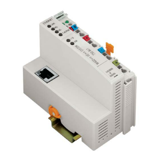
Modular I/O-System
Ethernet TCP/IP
750-841
Manual
Technical description,
installation and
configuration
Version 1.1.0
Advertisement
Table of Contents

Related Manuals for WAGO 750 Series


Summary of Contents for WAGO 750 Series
- Page 1 Modular I/O-System ETHERNET TCP/IP 750-841 Manual Technical description, installation and configuration Version 1.1.0...
- Page 2 • General Copyright © 2005 by WAGO Kontakttechnik GmbH All rights reserved. WAGO Kontakttechnik GmbH Hansastraße 27 D-32423 Minden Phone: +49 (0) 571/8 87 – 0 Fax: +49 (0) 571/8 87 – 1 69 E-Mail: info@wago.com Web: http://www.wago.com Technical Support Phone: +49 (0) 571/8 87 –...
-
Page 3: Table Of Contents
Number Notation ..................2 Safety Notes ..................... 3 Scope ......................4 Important Comments for Starting up............4 Abbreviation..................... 4 2 The WAGO-I/O-SYSTEM 750 ..............5 System Description................... 5 Technical Data..................6 Manufacturing Number ................9 Component Update................. 10 Storage, Assembly and Transport ............11 Mechanical Setup ................... -
Page 4: Table Of Contents
Protective measures ................213 Classification meeting CENELEC and IEC ......... 213 Classifications meeting the NEC 500........... 217 Identification ..................219 Installation regulations ................. 221 10 Glossary....................223 11 Literature List ..................235 12 Index ......................236 WAGO-I/O-SYSTEM 750 ETHERNET TCP/IP... -
Page 5: Important Comments
WAGO Kontakttechnik GmbH declines all liability resulting from improper action and damage to WAGO products and third party products due to non-observance of the information contained in this manual. -
Page 6: Symbols
<F5> i.e.: Courier Program code is printed with the font Courier. i.e.: END_VAR 1.4 Number Notation Number Code Example Note Decimal normal notation Hexadecimal 0x64 C notation Binary '100' Within ', '0110.0100' Nibble separated with dots WAGO-I/O-SYSTEM 750 ETHERNET TCP/IP... -
Page 7: Safety Notes
Do not use any contact spray. The spray may impair the functioning of the contact area. The WAGO-I/O-SYSTEM 750 and its components are an open system. It must only be assembled in housings, cabinets or in electrical operation rooms. Access must only be given via a key or tool to authorized qualified personnel. -
Page 8: Scope
4 • Important Comments Scope 1.6 Scope This manual describes the field bus independent WAGO-I/O-SYSTEM 750 with the programmable fieldbus controller for ETHERNET 10/100 MBit/s. Item.-No. Description 750-841 Prog. Fieldbus Controller EtherNet 10/100 MBit/s 1.7 Important Comments for Starting up... -
Page 9: The Wago-I/O-System 750
The WAGO-I/O-SYSTEM 750 has a clear port level with LEDs for status indication, insertable mini WSB markers and pullout group marker carriers. The 3-wire technology supplemented by a ground wire connection allows for direct sensor/actuator wiring. -
Page 10: Technical Data
6 • The WAGO-I/O-SYSTEM 750 Technical Data 2.2 Technical Data Mechanic Material Polycarbonate, Polyamide 6.6 Dimensions - Coupler / Controller - 51 mm x 65* mm x 100 mm - I/O module, single - 12 mm x 64* mm x 100 mm... - Page 11 The WAGO-I/O-SYSTEM 750 • 7 Technical Data Mechanical strength Vibration resistance acc. to IEC 60068-2-6 Comment to the vibration restistance: a) Type of oscillation: sweep with a rate of change of 1 octave per minute 10 Hz ≤ f < 57 Hz, const. Amplitude 0,075 mm 57 Hz ≤...
- Page 12 In Germany, the Federal Office for Post and Telecommunications and its branch offices issues the permit. It is possible to use other field bus couplers / controllers under certain boundary conditions. Please contact WAGO Kontakttechnik GmbH. Maximum power dissipation of the components Bus modules 0.8 W / bus terminal (total power dissipation,...
-
Page 13: Manufacturing Number
The WAGO-I/O-SYSTEM 750 • 9 Manufacturing Number Dimensions 01 02 24V 0V Side view Dimensions in mm Fig. 2-2: Dimensions g01xx05e 2.3 Manufacturing Number The manufacturing number indicates the delivery status directly after production. This number is part of the lateral marking on the component. -
Page 14: Component Update
10 • The WAGO-I/O-SYSTEM 750 Component Update ITEM-NO.:750-333 ITEM-NO.:750-333 PROFIBUS DP 12 MBd /DPV1 PROFIBUS DP 12 MBd /DPV1 Hansastr. 27 Hansastr. 27 D-32423 Minden D-32423 Minden 24 V Power Supply Power Supply Power Supply Field Electronic Electronic PATENTS PENDING... -
Page 15: Storage, Assembly And Transport
The WAGO-I/O-SYSTEM 750 • 11 Storage, Assembly and Transport 2.5 Storage, Assembly and Transport Wherever possible, the components are to be stored in their original packaging. Likewise, the original packaging provides optimal protection during transport. When assembling or repacking the components, the contacts must not be soiled or damaged. - Page 16 European standard EN 50022 (DIN 35). Warning WAGO supplies standardized carrier rails that are optimal for use with the I/O system. If other carrier rails are used, then a technical inspection and approval of the rail by WAGO Kontakttechnik GmbH should take place.
- Page 17 The WAGO-I/O-SYSTEM 750 • 13 Mechanical Setup 2.6.3.2 WAGO DIN Rail WAGO carrier rails meet the electrical and mechanical requirements. Item Number Description 210-113 /-112 35 x 7.5; 1 mm; steel yellow chromated; slotted/unslotted 210-114 /-197 35 x 15; 1.5 mm; steel yellow chromated; slotted/unslotted 210-118 35 x 15;...
- Page 18 14 • The WAGO-I/O-SYSTEM 750 Mechanical Setup 2.6.5 Plugging and Removal of the Components Warning Before work is done on the components, the voltage supply must be turned off. In order to safeguard the coupler/controller from jamming, it should be fixed onto the carrier rail with the locking disc To do so, push on the upper groove of the locking disc using a screwdriver.
- Page 19 The WAGO-I/O-SYSTEM 750 • 15 Mechanical Setup 2.6.6 Assembly Sequence All system components can be snapped directly on a carrier rail in accordance with the European standard EN 50022 (DIN 35). The reliable positioning and connection is made using a tongue and groove system.
- Page 20 16 • The WAGO-I/O-SYSTEM 750 Mechanical Setup 2.6.7 Internal Bus / Data Contacts Communication between the coupler/controller and the bus modules as well as the system supply of the bus modules is carried out via the internal bus. It is comprised of 6 data contacts, which are available as self-cleaning gold spring contacts.
- Page 21 Fig. 2-8: Example for the arrangement of power contacts g0xxx05e Recommendation With the WAGO ProServe® Software smartDESIGNER, the assembly of a fieldbus node can be configured. The configuration can be tested via the integrated accuracy check. WAGO-I/O-SYSTEM 750...
- Page 22 More than one conductor per connection is not permissible. If several conductors have to be made at one connection point, then they should be made away from the connection point using WAGO Terminal Blocks. The terminal blocks may be jumpered together and a single wire brought back to the I/O module connection point.
-
Page 23: Power Supply
The WAGO-I/O-SYSTEM 750 • 19 Power Supply 2.7 Power Supply 2.7.1 Isolation Within the fieldbus node, there are three electrically isolated potentials. • Operational voltage for the fieldbus interface. • Electronics of the couplers / controllers and the bus modules (internal bus). - Page 24 2.7.2 System Supply 2.7.2.1 Connection The WAGO-I/O-SYSTEM 750 requires a 24 V direct current system supply (-15% or +20 %). The power supply is provided via the coupler / controller and, if necessary, in addition via the internal system supply modules (750-613).
- Page 25 The WAGO-I/O-SYSTEM 750 • 21 Power Supply Attention Resetting the system by switching on and off the system supply, must take place simultaneously for all supply modules (coupler / controller and 750-613). 2.7.2.2 Alignment Recommendation A stable network supply cannot be taken for granted always and everywhere.
- Page 26 The WAGO-I/O-SYSTEM 750 Power Supply Recommendation With the WAGO ProServe® Software smartDESIGNER, the assembly of a fieldbus node can be configured. The configuration can be tested via the integrated accuracy check. The maximum input current of the 24 V system supply is 500 mA. The exact...
- Page 27 The WAGO-I/O-SYSTEM 750 • 23 Power Supply 2.7.3 Field Supply 2.7.3.1 Connection Sensors and actuators can be directly connected to the relevant channel of the bus module in 1-/4 conductor connection technology. The bus module supplies power to the sensors and actuators. The input and output drivers of some bus modules require the field side supply voltage.
- Page 28 24 • The WAGO-I/O-SYSTEM 750 Power Supply Attention Some bus modules have no or very few power contacts (depending on the I/O function). Due to this, the passing through of the relevant potential is disrupted. If a field supply is required for subsequent bus modules, then a power supply module must be used.
- Page 29 The WAGO-I/O-SYSTEM 750 • 25 Power Supply Warning In the case of power supply modules with fuse holders, only fuses with a maximum dissipation of 1.6 W (IEC 127) must be used. For UL approved systems only use UL approved fuses.
- Page 30 26 • The WAGO-I/O-SYSTEM 750 Power Supply Alternatively, fusing can be done externally. The fuse modules of the WAGO series 281 and 282 are suitable for this purpose. Fig. 2-18: Fuse modules for automotive fuses, Series 282 pf66800x Fig. 2-19: Fuse modules with pivotable fuse carrier, Series 281 pe61100x Fig.
- Page 31 • 27 Power Supply 2.7.4 Supplementary power supply regulations The WAGO-I/O-SYSTEM 750 can also be used in shipbuilding or offshore and onshore areas of work (e.g. working platforms, loading plants). This is demonstrated by complying with the standards of influential classification companies such as Germanischer Lloyd and Lloyds Register.
- Page 32 28 • The WAGO-I/O-SYSTEM 750 Power Supply 2.7.5 Supply example Note The system supply and the field supply should be separated in order to ensure bus operation in the event of a short-circuit on the actuator side. 750-400 750-410 750-401...
- Page 33 • 29 Power Supply 2.7.6 Power Supply Unit The WAGO-I/O-SYSTEM 750 requires a 24 V direct current system supply with a maximum deviation of -15% or +20 %. Recommendation A stable network supply cannot be taken for granted always and everywhere.
-
Page 34: Grounding
The optimal insulated setup is a metallic assembly plate with grounding connection with an electrical conductive link with the carrier rail. The separate grounding of the carrier rail can be easily set up with the aid of the WAGO ground wire terminals. Article No. Description... - Page 35 The WAGO-I/O-SYSTEM 750 • 31 Grounding 2.8.2 Grounding Function The grounding function increases the resistance against disturbances from electro-magnetic interferences. Some components in the I/O system have a carrier rail contact that dissipates electro-magnetic disturbances to the carrier rail. Fig. 2-23: Carrier rail contact...
- Page 36 32 • The WAGO-I/O-SYSTEM 750 Grounding 2.8.3 Grounding Protection For the field side, the ground wire is connected to the lowest connection terminals of the power supply module. The ground connection is then connected to the next module via the Power Jumper Contact (PJC). If the bus...
-
Page 37: Shielding (Screening)
Note For better shield performance, the shield should have previously been placed over a large area. The WAGO shield connection system is suggested for such an application. This suggestion is especially applicable when the equipment can have even current or high impulse formed currents running through it (for example through atmospheric end loading). -
Page 38: Assembly Guidelines / Standards
Assembly Guidelines / Standards 2.9.4 WAGO Shield (Screen) Connecting System The WAGO Shield Connecting system includes a shield clamping saddle, a collection of rails and a variety of mounting feet. Together these allow many dfferent possibilities. See catalog W4 volume 3 chapter 10. -
Page 39: Fieldbus Controller
Data Exchange between Master and PLC Functionality (CPU)... 76 3.1.7 Starting up an ETHERNET TCP/IP fieldbus node ......81 3.1.7.1 Variation 1: Start up with the WAGO Ethernet Settings....81 3.1.7.2 Variation 2:Starting up with the WAGO BootP Server....83 3.1.8 Programming the PFC with WAGO-I/O-PRO CAA...... - Page 40 ETHERNET fieldbus coupler with the functionality of a Programmable Logic Controller (PLC). When the PFC is used as a PLC, all or some of its I/O modules can be control locally with the use of WAGO-I/O- PRO CAA. WAGO-I/O-PRO CAA is an IEC 61131-3 programming tool that is used to program and configure the 750-841 PFC.
- Page 41 Controller compatible with WAGO-I/O-PRO version, independent of the controller hard- or software SW ≥ xy Controller compatible with WAGO-I/O-PRO version if the controller has software xy or higher Attention The CoDeSys network variables from WAGO-I/O-PRO V2.3.3.6 and higher are supported by the controllers 750-841 with the software SW ≥ 06.
- Page 42 • Fieldbus interface with the bus connection • Display Elements (LED's) for operation status, diagnostics, and communication status • Configuration and programming interface port • Operating mode switch • Electronics for communication with the I/O modules (internal bus) and the fieldbus interface WAGO-I/O-SYSTEM 750 ETHERNET TCP/IP...
- Page 43 10 nF 750-841 Fig. 3-2: Device supply G084101e The internal electronics of the controller and I/O modules are electrically isolated from the field-side power connections and field devices by the use of DC/DC converters and optocouplers WAGO-I/O-SYSTEM 750 ETHERNET TCP/IP...
- Page 44 The LED information is routed to the top of the case by light fibres. In some cases, these are multi-colored (red/green or red/green/orange). 01 02 01 02 01 02 ETHERNET ETHERNET ETHERNET LINK LINK LINK 24V 0V 24V 0V 24V 0V TxD/RxD TxD/RxD TxD/RxD Abb. 3-1: Display Elements 750-841 g084102x WAGO-I/O-SYSTEM 750 ETHERNET TCP/IP...
- Page 45 WAGO-I/O-PRO CAA, as well as for firmware downloading. Configuration and programming interface Fig. 3-2: Configuration Interface g01xx07e A WAGO 750-920 Communication Cable is used to connect the 4 pin male header and with a PC’s 9-pin RS232 interface. WAGO-I/O-SYSTEM 750 ETHERNET TCP/IP...
- Page 46 RUN in any position of the operating mode switch! An operating mode (i.e., RUN/STOP) is internally changed at the end of a PLC cycle. Note The position of the mode switch is not important when starting or stopping the PFC application from WAGO-I/O-PRO. WAGO-I/O-SYSTEM 750 ETHERNET TCP/IP...
- Page 47 3.1.3.7 Hardware Address (MAC-ID) Each WAGO ETHERNET TCP/IP fieldbus controller is supplied from the factory with a unique and internationally unambiguous physical ETHERNET address, also referred to as MAC-ID (Media Access Control Identity). This is located on the rear of the controller and on a self-adhesive tear-off label on the controller’s side.
- Page 48 The PLC cycle starts following a fault free start-up when the Operating Mode Switch is in the top position or by a start command from the WAGO-I/O-PRO CAA. The controller starts a PLC cycle by first reading the fieldbus data, I/O modules, and time data. Next, the PLC program in RAM is processed (scanned).
- Page 49 Fieldbus data, Writing outputs data of I/O modules Operating system functions, updating times operating mode switch is in the top position or STOP Operating mode start command in WAGO-IO- Online/Start Online/Stop Fig. 3-5: Controller Operating System g012941e WAGO-I/O-SYSTEM 750 ETHERNET TCP/IP...
- Page 50 (data width/bit width > 0). The maximal length of a node is limited to 64 I/O modules. Note Use of the WAGO 750-628 Bus Extension Coupler Module and the 750-627 Extension End Module enables support of up to 250 I/O modules on the 750-841 controller.
- Page 51 For future protocol additions, the area above word 1532 is reserved for additional PFC variables. With all WAGO fieldbus controllers, the method used by PLC functions to access process data is independent of the fieldbus system. This access always takes place via an application-related IEC 61131-3 program.
- Page 52 0x0006 %IX8.6 0x0007 %IX8.7 0x0007 %IX8.7 0x0008 %IX8.8 0x0009 %IX8.9 DI: Digital Input 0x000A %IX8.10 AI:Analog Input 0x000B %IX8.11 0x000C %IX8.12 0x000D %IX8.13 0x000E %IX8.14 0x000F %IX8.15 Fig. 3-6: Example of a Process Input Image G012924e WAGO-I/O-SYSTEM 750 ETHERNET TCP/IP...
- Page 53 (Bit) MODBUS addresses 0x0000 / 0x0200 %QX4.0 0x0001 / 0x0201 %QX4.1 Process input image (Bit) MODBUS addresses 0x0200 %QX4.0 0x0201 %QX4.1 DO: Digital Output AO: Analog Output Fig. 3-7: Example of a Process Output Image G012925e WAGO-I/O-SYSTEM 750 ETHERNET TCP/IP...
- Page 54 (with word alignment). The internal mapping method for data greater than one byte conforms to the Intel format. The following section describes the process image for various WAGO-I/O-SYSTEM 750 I/O modules when using an Ethernet TCP/IP coupler/controller. Note Depending on the specific position of an I/O module in the fieldbus node, the process data of all previous byte or bit-oriented modules must be taken into account to determine its location in the process data map.
- Page 55 DI 1 Channel 2 Channel 1 Channel Channel Output Process Image Bit 7 Bit 6 Bit 5 Bit 4 Bit 3 Bit 2 Bit 1 Bit 0 Acknowledge Acknowledg ment bit ement bit Channel 2 Channel 1 WAGO-I/O-SYSTEM 750 ETHERNET TCP/IP...
- Page 56 Bit 2 Bit 1 Bit 0 Status bit „Manual used Operation“ Output Process Image Bit 7 Bit 6 Bit 5 Bit 4 Bit 3 Bit 2 Bit 1 Bit 0 controls DO 1 used Channel 1 WAGO-I/O-SYSTEM 750 ETHERNET TCP/IP...
- Page 57 Bit 5 Bit 4 Bit 3 Bit 2 Bit 1 Bit 0 Diagnostic Diagnostic Diagnostic Diagnostic bit S 3 bit S 2 bit S 1 bit S 0 Channel 2 Channel 2 Channel 1 Channel 1 WAGO-I/O-SYSTEM 750 ETHERNET TCP/IP...
- Page 58 Output Process Image Bit 7 Bit 6 Bit 5 Bit 4 Bit 3 Bit 2 Bit 1 Bit 0 controls controls controls controls DO 4 DO 3 DO 2 DO 1 Channel Channel Channel Channel WAGO-I/O-SYSTEM 750 ETHERNET TCP/IP...
- Page 59 Intel format in the Input Process Image. When digital input modules are also present in the node, the analog input data is always mapped into the Input Process Image in front of the digital data. WAGO-I/O-SYSTEM 750 ETHERNET TCP/IP...
- Page 60 8 control/status bits. Therefore, the Ethernet coupler/controller can only access the 16 bits of analog data per channel, which are grouped as words and mapped in Intel format in the Output Process Image. WAGO-I/O-SYSTEM 750 ETHERNET TCP/IP...
- Page 61 Output Value Channel 4 3.1.5.4.5 Specialty Modules WAGO has a host of Specialty I/O modules that perform various functions. With individual modules beside the data bytes also the control/status byte is mapped in the process image. The control/status byte is required for the bi- directional data exchange of the module with the higher-ranking control system.
- Page 62 Input and Output Process Image, which has a total of 3 words mapped into each image. Word alignment is applied. Input Process Image Byte Destination Offset Remark High Byte Low Byte Status byte Counter Value of Counter 1 Counter Value of Counter 2 WAGO-I/O-SYSTEM 750 ETHERNET TCP/IP...
- Page 63 The two channel values are supplied as 16 bits. Each channel has its own control/status byte. The following table illustrates the Input and Output Process Image, which has a total of 4 words mapped into each image. Word alignment is applied. WAGO-I/O-SYSTEM 750 ETHERNET TCP/IP...
- Page 64 6 bytes of user data in both the Input and Output Process Image (5 bytes of serial data and 1 byte of control/status). The following table illustrates the Input and Output Process Image, which have a total of 3 words mapped into each image. Word alignment is applied. WAGO-I/O-SYSTEM 750 ETHERNET TCP/IP...
- Page 65 The above SSI Transmitter Interface modules have a total of 4 bytes of user data in the Input Process Image, which has 2 words mapped into the image. Word alignment is applied. Input Process Image Byte Destination Offset Remark High Byte Low Byte Data bytes WAGO-I/O-SYSTEM 750 ETHERNET TCP/IP...
- Page 66 Counter word (D2)* not used (Periodic time) Latch word If cycle duration measurement mode is enabled in the control byte, the cycle duration is given as a 24-bit value that is stored in D2 together with D3/D4. WAGO-I/O-SYSTEM 750 ETHERNET TCP/IP...
- Page 67 Input and Output Process Image (5 bytes of module data and 1 byte of control/status). The following tables illustrate the Input and Output Process Image, which have 3 words mapped into each image. Word alignment is applied. WAGO-I/O-SYSTEM 750 ETHERNET TCP/IP...
- Page 68 Input and Output Process Image (6 bytes of module data and 2 bytes of control/status). The following table illustrates the Input and Output Process Image, which have 4 words mapped into each image. Word alignment is applied. WAGO-I/O-SYSTEM 750 ETHERNET TCP/IP...
- Page 69 Input Process Image for monitoring of the internal power supply. Input Process Image Bit 7 Bit 6 Bit 5 Bit 4 Bit 3 Bit 2 Bit 1 Bit 0 Diagnostic bit S 2 Diagnostic bit S 1 Fuse Voltage WAGO-I/O-SYSTEM 750 ETHERNET TCP/IP...
- Page 70 IP address. Typically, the ETHERNET TCP/IP controller of the WAGO-I/O-SYSTEM is a slave device. But, with the use of the WAGO-I/O-PRO CAA programming tool, the PFC can additionally perform master functions. A controller is able to produce a defined number of simultaneous socket connections to other network subscribers: •...
- Page 71 CPU for further processing. (4) The variables processed by the controller’s CPU , via an IEC 61131-3 application program, can be written to the PFC Variables and then read by the fieldbus master. WAGO-I/O-SYSTEM 750 ETHERNET TCP/IP...
- Page 72 512 kByte After a successful start-up, the PFC cycle starts when the operating mode switch is turned to its upper position or by a start command from WAGO-I/O-PRO CAA. NOVRAM The remanent memory is non volatile memory, i.e. all values are Remanent retained following a voltage failure.
- Page 73 Partition of Address ranges for the word-wise addressing acc. to IEC 61131-3 : Word Data 0-255 physical I/O modules 256-511 MODBUS/TCP PFC variables 512-1275 remaining physical I/O modules 1276-1531 Ethernet/IP PFC variables 1532-..reserved for PFC variables of future protocols WAGO-I/O-SYSTEM 750 ETHERNET TCP/IP...
- Page 74 0.8... 1.0... 1.8..12287.0.. 12287.8.. 12288.0 ... 12288.8... 0.15 1.15 12287.7 12287.15 12288.7 12288.15 ..24572 24573 24574 24575 Byte ..12287 12288 Word ..6144 DWord Table 3.6: Address Range for Flags (Retain Variables) WAGO-I/O-SYSTEM 750 ETHERNET TCP/IP...
- Page 75 %QW27 (28. Word), bit wise: %IX1.9 (10. Bit in Word 2) * The character ‘X’ for bits can be deleted Table 3.8: Absolute Addresses Note Enter the absolute address character strings without blanks (white spaces)! WAGO-I/O-SYSTEM 750 ETHERNET TCP/IP...
- Page 76 The relationship between bits and words are defined in the table below: 15. 14. 13. 12. 11. 10. 9. Digital inputs/outputs Prozess data word High-Byte Low-Byte Byte Table 3.9: Allocation of Digital Inputs/Outputs to Process Data Word in Intel Format WAGO-I/O-SYSTEM 750 ETHERNET TCP/IP...
- Page 77 The MODBUS register assignments allow for a Fieldbus Master to read and write data from the controller. The register mapping for IEC 61131.1 varies from the MODBUS assignments. Please refer to section 3.1.5.6.2 for a comparison of MODBUS TCP and IEC 61131.1 address mapping. WAGO-I/O-SYSTEM 750 ETHERNET TCP/IP...
- Page 78 I/O links. The mapping of the data depends on the chosen assembly instance of the static assembly. Further information The assembly instances for the static assembly are described in the section 7.3.2.6 "Assembly (04 hex)". WAGO-I/O-SYSTEM 750 ETHERNET TCP/IP...
- Page 79 %QW0 %QW512 %IW255 %IW1275 %QW255 %QW1275 Outputs Inputs PLC functionality (CPU) PII = Process Input Image PIO = Process Output Image Programmable Fieldbus Controller Fig. 3-10: Data exchange between PLC functionality (CPU) and I/O modules 15043e WAGO-I/O-SYSTEM 750 ETHERNET TCP/IP...
- Page 80 The “WORD.BIT” notation is composed of the boolean’s word address and bit number in the word, separated by a dot. The Word and Bit values are zero based (e.g., %IX0.0 is the first possible digital input). WAGO-I/O-SYSTEM 750 ETHERNET TCP/IP...
- Page 81 High-Byte Address = Word address*2 Low-Byte Address = (Word address*2) + 1 The double word address is computed according to the following formula: Double word address = High word address/2 (rounded off) or = Low word address/2 WAGO-I/O-SYSTEM 750 ETHERNET TCP/IP...
- Page 82 Firmware register 0x2FFF 12288... 0x3000 - %MW0... Flags range (default: 13385 0x3FFF %MW4095 8kByte, size changeable) 24576 ... 0x6000- %QW512... phys. Outputs (2) 25340 0x62FC %QW1275 28672 ... 0x7000- %QW512... phys.. Outputs (2) 29436 0x72FC %QW1275 WAGO-I/O-SYSTEM 750 ETHERNET TCP/IP...
- Page 83 12287 0x2FFF %IX511.15 12288... 0x3000 - %MX0.0... Flags range (default: 32767 0x7FFF %MX1279.15 8kByte, size changeable) 32768... 0x8000 - %QX512.0 .. phys. Outputs (2) 34295 0x85F7 %QX1275.15 34296... 0x9000 - %QX512.0 .. 38391 0x95F7 % QX1275.15 WAGO-I/O-SYSTEM 750 ETHERNET TCP/IP...
- Page 84 DI : Digital Input Module Flags AI : Analog Input Module (Word, Bit) DO: Digital Output Module Adressen AO: Analog Output Module MODBUS 0x3560 %MW86 0x34B6 %MX75.6 Abb. 3-3: Example: Addressing of a Fieldbus node g012948e WAGO-I/O-SYSTEM 750 ETHERNET TCP/IP...
- Page 85 Additionally in the following chapters, it covers details regarding PFC programming with WAGO-I/O-PRO CAA and provides information about the built-in HTML web pages. 3.1.7.1 Variation 1: Start up with the WAGO Ethernet Settings This procedure contains the following steps: 1. Connecting the PC and fieldbus node 2.
- Page 86 Starting up an ETHERNET TCP/IP fieldbus node Note You can download a free copy of the WAGO Ethernet Settings" which you can find on the „ELECTRONICC Tools and Docs“ CD ROM (Item-No.: 0888-0412-0001-0101) and on the WAGO Web pages under www.wago.com, "Service...
- Page 87 Fieldbus Controller 750-841 • 83 Starting up an ETHERNET TCP/IP fieldbus node 3.1.7.2 Variation 2:Starting up with the WAGO BootP Server This procedure contains the following steps: 6. Noting the MAC-ID and establishing the fieldbus node 7. Connecting the PC and fieldbus node 8.
- Page 88 A prerequisite for communication with the controller is the assignment of an IP address. The address can be transferred through the "WAGO BootP Server" or a PFC program. With the PFC program, this is possible in WAGO-I/O-PRO CAA using the fuction block "ETHERNET_Set_Network_Config"...
- Page 89 Fieldbus Controller 750-841 • 85 Starting up an ETHERNET TCP/IP fieldbus node You can download a free copy of the WAGO’s BootP server over the Internet under at http://www.wago.com/- “Service“/“Downloads“/“Software“/“ELECTRONICC“/- ‘WAGO BootPServer V1.0 Windows 95/NT - ZIP Archiv‘. Note The IP address can be allocated under other operating systems (e.g. under Linux) as well as with any other BootP servers.
- Page 90 File menu, menu item Save, and then close the editor. BootP Server 8. Now open the dialog window for the WAGO BootP server by going to the Start menu on your screen surface, menu item Program / WAGO Software / WAGO BootP Server and click on WAGO BootP Server.
- Page 91 Fieldbus Controller 750-841 • 87 Starting up an ETHERNET TCP/IP fieldbus node Fig. 3-13 Dialog Window of the WAGO BootP Server with Messages P012909d 10. Now it is important to restart the controller by resetting the hardware. To do this, cycle power to the fieldbus controller for approximately 2 seconds or press the operating mode switch down, which is located behind the configuration interface flap on the front of the controller.
- Page 92 5. To logon as the administrator, enter the user name admin and the password wago. Note If the controller does not display the opening HTML page, make sure your web browser is setup to bypass the proxy server for local addresses. WAGO-I/O-SYSTEM 750 ETHERNET TCP/IP...
- Page 93 To do this, either switch off the power supply of the controller or press down the operating mode switch. 9. The protocol settings are now stored EEPROM and the controller is ready to operate. WAGO-I/O-SYSTEM 750 ETHERNET TCP/IP...
- Page 94 ETHERNET fieldbus coupler with the functionality of a Programmable Logic Controller (PLC). When the PFC is used as a PLC, all or some of its I/O modules can be control locally with the use of WAGO-I/O- PRO CAA. WAGO-I/O-PRO CAA is an IEC 61131-3 programming tool that is used to program and configure the 750-841 PFC.
- Page 95 Programming the PFC with WAGO-I/O-PRO CAA Configuration with the WAGO-I/O-PRO CAA I/O-Configurator 1. To configure the I/O of the fieldbus node in WAGO-I/O-PRO, select the Resources tab in the left window of the screen, then double click on PLC configuration in the tree structure.
- Page 96 IEC 61131-3 program tool. The configuration file “EA-config.xml” is generated as soon as you compile the project. More information For a detailed description on how to use the software WAGO-I/O-PRO CAA and the I/O-Configurator, please refer to the Online-Help of WAGO-I/O-PRO CAA.
- Page 97 2. To access the file system of the controller, enter the IP address of the controller in the FTP client. Also, set the user name to admin and the password to wago. The “EA-config.xml” file can be found in the folder etc. on the PFC server.
- Page 98 For information on the function blocks as well as details regarding the use of the software, please refer to the WAGO-I/O-PRO CAA manual or the onlinehelp. An electronic copy of the manual can be found on WAGO’s web site: www.wago.com.
- Page 99 Fieldbus Controller 750-841 • 95 Programming the PFC with WAGO-I/O-PRO CAA 3.1.8.2 Some Basic Facts about IEC Tasks Attention Consider please with the programming of your IEC tasks the following facts. • All IEC tasks must have a different priority level. If two tasks have the same level, an error message is displayed when the program is compiled.
- Page 100 (e.g., SysLibFile functions) More information For detailed information on the programming tool WAGO-I/O-PRO CAA, please refer to the WAGO-I/O-PRO CAA manual. An electronic copy of this manual can be found on WAGO’s web site: www.wago.com 3.1.8.2.3 System Events...
- Page 101 Possible events are for instance: Stop, Start, Online Change. The complete list of all system events is specified in WAGO-I/O-PRO CAA /register "Resources"/"Task configuration"/"System events".
- Page 102 For information on the installation of the communication drivers, as well as details regarding the use of the software, please refer to the WAGO-I/O-PRO CAA manual. An electronic copy of this manual can be found on WAGO’s web site: www.wago.com...
- Page 103 Programming the PFC with WAGO-I/O-PRO CAA 3.1.8.3.1 Transmission via the Serial Interface Use the WAGO communication cable to produce a physical connection to the serial interface. This is contained in the scope of delivery of the programming tool IEC 1131-3, order No.: 759-333/000-002, or can be purchased as an accessory under order No.: 750-920.
- Page 104 WAGO-I/O-PRO CAA, this driver and its parameters are entered in the Communication Parameters dialog. 1. Start WAGO-I/O-PRO CAA by using the Windows Start menu, find and click on the WAGO-I/O-PRO program name (i.e., CoDeSys V2.3). 2. In the Online program menu, click Communication parameters. The dialog window Communication parameters opens.
- Page 105 Fieldbus Controller 750-841 • 101 Programming the PFC with WAGO-I/O-PRO CAA 3.1.8.4 Information on the web-based management system In addition to the web pages already described in section 3, the following HTML pages are stored in your controller and provide information and configuration options.
- Page 106 102 • Fieldbus Controller 750-841 Programming the PFC with WAGO-I/O-PRO CAA Port Under the link Port you can get the HTML page "Port configuration" on that you can activate or deactivate wished protocols. FTP, HTTP, WebVisu, MODBUS TCP, MODBUS UDP, CoDeSys and BOOTP are activated by default.
- Page 107 Fieldbus Controller 750-841 • 103 Programming the PFC with WAGO-I/O-PRO CAA Watchdog Under the Watchdog link, you can view and change settings for the MODBUS Watchdog. Clock Under the Clock link, you can view and change settings for the controller' s internal real time clock.
- Page 108 104 • Fieldbus Controller 750-841 Programming the PFC with WAGO-I/O-PRO CAA Ethernet Under the Ethernet link, you can view and change settings for the data transmission rate and the bandwidth limitation for the Ethernet transmission. These should be changed however only in completely special cases. The bandwidth limitation can be activated or deactivated.
- Page 109 Fieldbus Controller 750-841 • 105 Programming the PFC with WAGO-I/O-PRO CAA Under the PLC link you can define the status of the outputs, if your application program stops. If there is a checkmark in the small box behind "Enabled", all outputs are set to zero, otherwise the outputs remain to the last current value.
- Page 110 In this case, always fieldbus 1, that means Modbus_TCP (Default), has the r write access rigths on the outputs. More Information Please, find detailed information about the WAGO-I/O-PRO CAA I/O- Configurator in chapter 3.1.7 "Starting up an ETHERNET TCP/IP fieldbus node".
- Page 111 Fieldbus Controller 750-841 • 107 Programming the PFC with WAGO-I/O-PRO CAA Samples Under the Samples link, a sample HTML page is provided, which you can use as a starting point to create your own web page. You can then store this or any other web page you have created into the file system of the controller using FTP download.
- Page 112 The second group of LEDs are three-color LEDs (red/green/orange). One of the LED is labelled ‘I/O’, and displays the status of the internal bus. The other is labelled ‘USR’, and is programmable with WAGO-I/O-PRO CAA. The third group uses solid colored LEDs. They are located on the right-hand side of the controller power supply.
- Page 113 No IP address is assigned to the system. Assign to the system an IP address by BootP, DHCP or the Ethernet Settings tool. TxD/RxD green Data exchange via ETHERNET taking place No data exchange via ETHERNET WAGO-I/O-SYSTEM 750 ETHERNET TCP/IP...
- Page 114 “I/O”-LED is shining Error argument (Number of flash cycles) ready for operation Fig. 3-16: Signalling of the LED for indication of the node status g012111e After clearing a fault, restart the coupler by cycling the power. WAGO-I/O-SYSTEM 750 ETHERNET TCP/IP...
- Page 115 Replace the faulty I/O module. Ask about a firmware update for the fieldbus coupler. Invalid fieldbus Turn off the power supply of the coupler/controller parameter node, reduce number of I/O checksum modules and turn the power supply on again WAGO-I/O-SYSTEM 750 ETHERNET TCP/IP...
- Page 116 Turn off the power supply of the Mailbox I/O modules exceeded node, reduce number of Gateway or Mailbox I/O modules and turn the power supply on again. Fault code 2: -not used- Fault argument Fault description Trouble shooting not used WAGO-I/O-SYSTEM 750 ETHERNET TCP/IP...
- Page 117 I/O module is detected. Replace the faulty I/O module. If there is only one I/O module left but the LED is still blinking, then this I/O module or the coupler is defective. Replace defective component. WAGO-I/O-SYSTEM 750 ETHERNET TCP/IP...
- Page 118 Replace defective component. Interruption of the internal bus Turn off the power supply of the after the n process data module. node, exchange the (n+1) process data module and turn the power supply on again. WAGO-I/O-SYSTEM 750 ETHERNET TCP/IP...
- Page 119 I/O Support. An IEC task exceeded the Check the task configuration maximum running time or the concerning the adjusted sampling sampling interval of the IEC task intervals and watchdog times. could not be kept (Watchdog) WAGO-I/O-SYSTEM 750 ETHERNET TCP/IP...
- Page 120 3.1.9.3 ‘USR‘-LED The state of the ‘USR‘ LED is programmable with WAGO-I/O-PRO CAA. Functions in the program library ”Visual.lib“ can be used to control the LED state. One of the many possible uses of this LED is to indicate the RUN/STOP state of your controller.
- Page 121 This message is decoded from the blink code, in the form of a fault code and fault argument. Once the internal bus fault is fixed, the controller is restarted by cycling its power. At this point the transfer of the process data resumes and the outputs are updated. WAGO-I/O-SYSTEM 750 ETHERNET TCP/IP...
- Page 122 Non-valatile memory 24 kByte (16 k retain, 8 k flags) Max. no. of socket connections 3 HTTP, 15 MODBUS/TCP, 10 FTP, 2 SNMP, 5 for IEC 61131-3 programs, 2 for WAGO-I/O-PRO CAA, 128 for Ethernet/IP Powerfail-RTC-Buffer min. 6 days Voltage supply DC 24 V (-15 % …...
-
Page 123: I/O Modules
You will find these manuals on CD ROM „ELECTRONICC Tools and Docs“ (Item-no.: 0888-0412-0001-0101) or on the web pages: www.wago.com / Support / Tech. Documentation / WAGO-I/O-SYSTEM 750 / Manuals / I/O Modules. More Information Current information on the modular WAGO-I/O-SYSTEM is available in the Internet under: www.wago.com... - Page 124 750-435 1 Channel, NAMUR EEx i, Proximity switch acc. to DIN EN 50227 750-438 2 Channel, NAMUR EEx i, Proximity switch acc. to DIN EN 50227 Intruder Detection 750-424 2 Channel, DC 24 V, Intruder Detection WAGO-I/O-SYSTEM 750 ETHERNET TCP/IP...
-
Page 125: Digital Output Modules
2 Channel, AC 230 V, DC 30 V, AC/DC 2 A, non-floating, 2 make contacts 750-513 2 Channel, AC 230 V, DC 30 V, AC/DC 2 A, isolated outputs, 2 make contacts 750-523 1 Channel, AC 230 V, AC 16 A, isolated output, 1 make contact, bistable, manual operation WAGO-I/O-SYSTEM 750 ETHERNET TCP/IP... -
Page 126: Analog Intput Modules
2 Channel, Resistance Sensors, PT100 / RTD, EEx i 003-000 750-460 4 Channel, Resistance Sensors, PT100 / RTD 750-469 2 Channel, thermocouples with diagnostics Sensor types: J, K, B, E, N, R, S, T, U, L 750-491 1 Channel for Resistor Bridges (Strain Gauge) WAGO-I/O-SYSTEM 750 ETHERNET TCP/IP... -
Page 127: Analog Output Modules
Digital Pulse Interface Serial Interfaces 750-650 Serial Interface RS 232 C 750-653 Serial Interface RS 485 750-651 TTY-Serial Interface, 20 mA Current Loop 750-654 Data Exchange Module DALI / DSI Master Module 750-641 DALI / DSI Master Module WAGO-I/O-SYSTEM 750 ETHERNET TCP/IP... -
Page 128: System Modules
750-604 Field Side Connection Module, DC 0 V Separation Modules 750-616 Separation Module 750-621 Separation Module with Power Contacts Binary Spacer Module 750-622 Binary Spacer Module End Module 750-600 End Module, to loop the internal bus WAGO-I/O-SYSTEM 750 ETHERNET TCP/IP... -
Page 129: Ethernet
The TCP/IP protocol stack offers a high degree of reliability for the transmission of information. In the ETHERNET TCP/IP fieldbus controller developed by WAGO, various application protocols have been implemented on the basis of the TCP/IP stack. These protocols allow the user to create applications (master applications) with standardized interfaces and transmit process data via an ETHERNET interface. -
Page 130: Network Architecture – Principles And Regulations
It is possible to connect 64 I/O modules to an ETHERNET TCP/IP fieldbus coupler/controller. Note Use of the WAGO 750-628 Bus Extension Coupler Module and 750-627 Extension End Module enables support of up to 250 I/O modules on the 750-841 controller (with softwareversion ≥ SW 9). - Page 131 The “T” and “F” stand for ‘twisted pair’ and ‘fiber optic’, and simply indicate the cable type. 10Base-T, 100BaseTX Either the 10BaseT standard or 100BaseTX can be used for the WAGO ETHERNET fieldbus node. The network architecture is very easy and inexpensive to assemble with S- UTP cable as transmission medium or with cables of STP type.
- Page 132 “data traffic cop” where the hub “polices” the data coming in and going out of the individual ports, so the data will only be transmitted to the required node. WAGO recommends using a switch rather then a hub, this will allow for a more deterministic architecture.
- Page 133 Stations can be added or removed without network interruption. Moreover, in the event of a defective cable, only the network segment and the node connected to this segment is impaired. This considerably increases the fail-safe of the entire network. WAGO-I/O-SYSTEM 750 ETHERNET TCP/IP...
- Page 134 UTP cabling is used. If there is a combination of fiber optic backbone and UTP cabling, the rule is simply translated to 7-6-5 rule. WAGO-I/O-SYSTEM 750 ETHERNET TCP/IP...
- Page 135 Matches topology changes and incompatible packet sizes (e.g. used in industrial and office areas). Gateway Links two manufacturer-specific networks which use different software and hardware (i.e., ETHERNET and Interbus-Loop). Tab. 5-2: Comparison of Coupler Modules for Networks WAGO-I/O-SYSTEM 750 ETHERNET TCP/IP...
- Page 136 Collisions may occur and messages have to be repeatedly transmitted as a result of the large amount of data traffic. The delay time in a Shared ETHERNET cannot be easily calculated or predicted. Fig. 5-6: Principle of Shared ETHERNET G012910e WAGO-I/O-SYSTEM 750 ETHERNET TCP/IP...
- Page 137 The message is then only sent to the node with the correct target address. This reduces the data traffic over the network, extends the bandwidth and prevents collisions. The runtimes can be defined and calculated, making the Switched Ethernet deterministic. Fig. 5-7: Principle of Switched ETHERNET G012909e WAGO-I/O-SYSTEM 750 ETHERNET TCP/IP...
-
Page 138: Network Communication
134 • ETHERNET Network Communication 5.3 Network Communication Fieldbus communication between master application and WAGO ETHERNET controller 750-841 can take place using either the MODBUS protocol or Ethernet/IP. The protocol layer model helps to explain the classification and interrelationships between the communication and application protocols. - Page 139 Ethernet/IP. Application device profiles (e.g. positioning controllers, semi- conductors, pneumatic valves) CIP application objects library CIP data management services (explicit messages, I/O messages) CIP message routing, connection management Encapsulation protocol TCP, UDP Ethernet (physical interface, CSMA/CD) WAGO-I/O-SYSTEM 750 ETHERNET TCP/IP...
- Page 140 136 • ETHERNET Network Communication 5.3.2 Communication Protocols In addition to the ETHERNET standard, the following important communication protocols are implemented in the WAGO ETHERNET TCP/IP fieldbus controller: • IP Version 4 (Raw-IP and IP-Multicast ) • TCP • UDP •...
- Page 141 Network Communication 5.3.2.1 ETHERNET ETHERNET address (MAC-ID) Each WAGO ETHERNET fieldbus coupler is provided from the factory with a unique and internationally unambiguous physical ETHERNET address, also referred to as MAC-ID (Media Access Control Identity). This can be used by the network operating system for addressing on a hardware level.
- Page 142 The highest bits in Class B networks are always 10. Meaning the highest byte can be in a range of 10 000000 to 10 111111. Therefore, the address range of Class B networks in the first byte is always between 128 and 191. WAGO-I/O-SYSTEM 750 ETHERNET TCP/IP...
- Page 143 192.000.000.XXX - Ca. 2 million Class C 223.255.255.XXX Each WAGO ETHERNET fieldbus coupler/controller can be easily assigned an IP address via the implemented BootP protocol. For small internal networks we recommend selecting a network address from Class C. Attention Never set all bits to equal 0 or 1 in one byte (byte = 0 or 255). These are reserved for special functions and may not be allocated.
- Page 144 The recipient node, which is located on a subnet initially, calculates the correct network number from its own IP address and the subnet mask. Only then does it check the node number and delivers the entire packet frame, if it corresponds. WAGO-I/O-SYSTEM 750 ETHERNET TCP/IP...
- Page 145 However, the connection must beforehand have been configured with a fixed IP address. The advantages of RAW IP are high data transfer rate and good stability. WAGO-I/O-SYSTEM 750 ETHERNET TCP/IP...
- Page 146 Examples: Telnet Port number: 23 HTTP Port number: 80 A complete list of "standardized services" is contained in the RFC 1700 (1994) specifications. WAGO-I/O-SYSTEM 750 ETHERNET TCP/IP...
- Page 147 5.3.4 Application Protocols In addition to the communication protocols described above, various application protocols are implemented in the WAGO ETHERNET Coupler. These protocols allow the user easy access to the fieldbus nodes: • MODBUS TCP (UDP) •...
- Page 148 (High byte, Low identifier receiver) (is always 0) byte) (Slave function address) code Fig. 5-12: MODBUS/TCP Header More information The structure of a datagram is specific for the individual function. Refer to Chapter "MODBUS functions". WAGO-I/O-SYSTEM 750 ETHERNET TCP/IP...
- Page 149 These objects enable plug-and-play interoperability between complex devices of different manufacturers. Further information A detailed description of the object model and its application is available in Chapter 7 "Ethernet/IP (Ethernet/Industrial Protocol). WAGO-I/O-SYSTEM 750 ETHERNET TCP/IP...
- Page 150 The dynamic configuration of the IP address via a BootP server offers the user a flexible and simple design of his network. The WAGO BootP server allows any IP address to be easily assigned for the WAGO fieldbus coupler/controller.
- Page 151 DHCP server, a BootP server, or the data stored in its EEPROM by default. Note The network configuration via DHCP is not stored in the EEPROM, this only occurs when using the BootP protocol. WAGO-I/O-SYSTEM 750 ETHERNET TCP/IP...
- Page 152 The addresses of the DNS server are configured via DHCP or web-based management. Up to 2 DNS servers can be specified. The host identification can be achieved with two functions, an internal host table is not supported. WAGO-I/O-SYSTEM 750 ETHERNET TCP/IP...
- Page 153 Due to the storage process, access times during write cycles are long. Note Up to 1 million write cycles are possible for writing to the flash memory for the file system. WAGO-I/O-SYSTEM 750 ETHERNET TCP/IP...
- Page 154 Deletes file Changes directory LIST Gives the directory list NLST Gives the directory list Deletes directory Gives the actually path Puts on a dirctory The TFTP (Trival File Transfer Protocol) is not supported by the controller. WAGO-I/O-SYSTEM 750 ETHERNET TCP/IP...
- Page 155 • 1.3.6.1.2.1.3 Address Translation Group • 1.3.6.1.2.1.4 IP Group • 1.3.6.1.2.1.4.21 IpRoute Table • 1.3.6.1.2.1.4.22 IpNetToMediaTable • 1.3.6.1.2.1.5 ICMP Group • 1.3.6.1.2.1.6 TCP Group • 1.3.6.1.2.1.7 UDP Group • 1.3.6.1.2.1.11 SNMP Group • 1.3.6.1.2.1.8 EGP Group WAGO-I/O-SYSTEM 750 ETHERNET TCP/IP...
- Page 156 Identifier Entry Description cess 1.3.6.1.2.1.1.1 sysDescr This entry contains the device identification. The entry is fix coded on "WAGO 750-841". 1.3.6.1.2.1.1.2 sysObjectID This entry contains the authorizing identification of the manufacturer. 1.3.6.1.2.1.1.3 sysUpTime This entry contains the time in hundredth seconds since the last reset of the managements unit.
- Page 157 Each entry contains the allocation between network address and hardware address. 1.3.6.1.2.1.3.1.1.1 atIfIndex R/W Contains the number of interface 1.3.6.1.2.1.3.1.1.2 atPhysAddress R/W Contains the medium independant hardware address 1.3.6.1.2.1.3.1.1.3 atNetAddress R/W Contains the IP address associated to the hardware address. WAGO-I/O-SYSTEM 750 ETHERNET TCP/IP...
- Page 158 Value of the last significant bit in the IP Addr broadcast address 1.3.6.1.2.1.4.20.1. ipAdEntReasm The size of the longest IP telegram that can be MaxSize re-assembled again. 1.3.6.1.2.1.4.23 ipRoutingDis Number of deleted Routing entries cards WAGO-I/O-SYSTEM 750 ETHERNET TCP/IP...
- Page 159 Entry 1.3.6.1.2.1.4.22.1.1 ipNetToMediaIf R/W Index for the interface Index 1.3.6.1.2.1.4.22.1. ipNetToMedia R/W The hardware address of the interface PhysAddress 1.3.6.1.2.1.4.22.1. ipNetToMedia R/W The IP address of the interface NetAddress 1.3.6.1.2.1.4.22.1. ipNetToMedia R/W Kind of mapping Type WAGO-I/O-SYSTEM 750 ETHERNET TCP/IP...
- Page 160 Number of sent ICMP timestamp request messages 1.3.6.1.2.1.5.24 icmpOutTimestamp Number of sent ICMP timestamp reply Reps messages 1.3.6.1.2.1.5.25 icmpOutAddrMasks Number of sent ICMP address mask request messages 1.3.6.1.2.1.5.26 icmpOutAddrMask Number of sent ICMP address mask Reps reply messages WAGO-I/O-SYSTEM 750 ETHERNET TCP/IP...
- Page 161 Entry Description cess 1.3.6.1.2.1.7.1 udpInDatagrams Number of received UDP frames that could be passed on the appropriate applications 1.3.6.1.2.1.7.2 udpNoPorts Number of received UDP frames that could not be passed on the appropriate applications (port unreachable) WAGO-I/O-SYSTEM 750 ETHERNET TCP/IP...
- Page 162 SET requests 1.3.6.1.2.1.11.18 snmpInGetResponses R Number of received GET responses 1.3.6.1.2.1.11.19 snmpInTraps Number of received Traps 1.3.6.1.2.1.11.20 snmpOutTooBigs Number of sent SNMP frames that contained the result too Big 1.3.6.1.2.1.11.21 snmpOutNoSuch Number of sent SNMP frames that WAGO-I/O-SYSTEM 750 ETHERNET TCP/IP...
- Page 163 SMTP hosts are installed in many networks, which are permanently switched on to enable distribution of received mail to the desktop computers. This protocol is made available to the user via a function block in the PFC application. WAGO-I/O-SYSTEM 750 ETHERNET TCP/IP...
-
Page 164: Modbus Functions
6 MODBUS Functions 6.1 General Various MODBUS functions from the OPEN MODBUS / TCP SPECIFICATION are found in the application layer of the WAGO ETHERNET fieldbus controller. More information More information on the OPEN MODBUS / TCP SPECIFICATION you can find in the Internet: www.modbus.org. -
Page 165: Use Of The Modbus Functions
0x000B 0x000C MODBUS addresses 0x000D 0x0200 0x000E 0x000F 0x0201 Fig. 6-1: Use of the MODBUS Functions G012918e Attention It is recommended that analog data be accessed with register functions and digital data with coil functions . WAGO-I/O-SYSTEM 750 ETHERNET TCP/IP... -
Page 166: Description Of The Modbus Functions
MODBUS Functions Description of the MODBUS Functions 6.3 Description of the MODBUS Functions All MODBUS functions in the WAGO ETHERNET fieldbus coupler and controller are executed as follows: A MODBUS TCP master (e.g., a PC) makes a request to the fieldbus controller using a specific function code based on the desired operation. - Page 167 0 0 0 1 0 0 1 0 Coil: 7 6 5 4 3 2 1 0 Exception Byte Field name Example ..Byte 7 MODBUS function code 0x81 Byte 8 Exception code 0x01 or 0x02 WAGO-I/O-SYSTEM 750 ETHERNET TCP/IP...
- Page 168 0 0 0 1 0 0 1 0 Coil: 7 6 5 4 3 2 1 0 Exception Byte Field name Example ..Byte 7 MODBUS function code 0x82 Byte 8 Exception code 0x01 or 0x02 WAGO-I/O-SYSTEM 750 ETHERNET TCP/IP...
- Page 169 The contents of register 0 are displayed by the value 0x1234 and the contents of register 1 is 0x2345. Exception Byte Field name Example ..Byte 7 MODBUS function code 0x83 Byte 8 Exception code 0x01 or 0x02 WAGO-I/O-SYSTEM 750 ETHERNET TCP/IP...
- Page 170 The contents of register 0 are shown by the value 0x1234 and the contents of register 1 is 0x2345. Exception Byte Field name Example ..Byte 7 MODBUS function code 0x84 Byte 8 Exception code 0x01 or 0x02 WAGO-I/O-SYSTEM 750 ETHERNET TCP/IP...
- Page 171 MODBUS function code 0x05 Byte 8, 9 Reference number 0x0001 Byte 10 Value 0xFF Byte 11 0x00 Exception Byte Field name Example ..Byte 7 MODBUS function code 0x85 Byte 8 Exception code 0x01, 0x02 or 0x03 WAGO-I/O-SYSTEM 750 ETHERNET TCP/IP...
- Page 172 Byte 7 MODBUS function code 0x06 Byte 8, 9 Reference number 0x0001 Byte 10, 11 Register Value 0x1234 Exception Byte Field name Example ..Byte 7 MODBUS function code 0x85 Byte 8 Exception code 0x01 or 0x02 WAGO-I/O-SYSTEM 750 ETHERNET TCP/IP...
- Page 173 0x0000 Byte 10, 11 Event Count 0x0003 The event counter shows that 3 (0x0003) events were counted. Exception Byte Field name Example ..Byte 7 MODBUS function code 0x85 Byte 8 Exception code 0x01 or 0x02 WAGO-I/O-SYSTEM 750 ETHERNET TCP/IP...
- Page 174 Byte 7 MODBUS function code 0x0F Byte 8, 9 Reference number 0x0000 Byte 10, 11 Bit Count 0x0010 Exception Byte Field name Example ..Byte 7 MODBUS function code 0x8F Byte 8 Exception code 0x01 or 0x02 WAGO-I/O-SYSTEM 750 ETHERNET TCP/IP...
- Page 175 Byte 7 MODBUS function code 0x10 Byte 8, 9 Reference number 0x0000 Byte 10, 11 Register Value 0x0002 Exception Byte Field name Example ..Byte 7 MODBUS function code 0x85 Byte 8 Exception code 0x01 or 0x02 WAGO-I/O-SYSTEM 750 ETHERNET TCP/IP...
- Page 176 MODBUS function code 0x10 Byte 8-9 Reference Number 0x0000 Byte 10-11 AND-Mask 0x0000 Byte 12-13 OR-Mask 0xAAAA Exception Byte Field name Example ..Byte 7 MODBUS function code 0x85 Byte 8 Exception code 0x01 or 0x02 WAGO-I/O-SYSTEM 750 ETHERNET TCP/IP...
- Page 177 Register Values 0x0004 (B+1) 0x5678 Exception Byte Field name Example ..Byte 7 MODBUS function code 0x97 Byte 8 Exception code 0x01 or 0x02 Note If register areas for read and write overlap, the results are undefined. WAGO-I/O-SYSTEM 750 ETHERNET TCP/IP...
-
Page 178: Modbus Register Mapping
Output registers of the PFC variables (MODBUS TCP) 0x1000 0x2FFF Internal variables (see next Chapter 6.5) 0x3000 0x5FFF NOVRAM (24 kByte) Retain range for flags 0x6000 0x62FC physical Outputs process image (2) 0x7000 0x72FC physical Outputs process image (2) WAGO-I/O-SYSTEM 750 ETHERNET TCP/IP... -
Page 179: Internal Variables
0x1022 Number of analog output data in the process image (in bits) 0x1023 Number of analog input data in the process image (in bits) 0x1024 Number of digital output data in the process image (in bits) WAGO-I/O-SYSTEM 750 ETHERNET TCP/IP... -
Page 180: Wago-I/O-System
Description of the connected busmodules (module 129-192) 0x2033 Description of the connected busmodules (module 193-255) 0x2040 Software reset (Write sequence 0x55AA or 0xAA55) 0x2041 Format Flash-Disk 0x2042 Extract HTML sides from the firmware 0x2043 Factory Settings WAGO-I/O-SYSTEM 750 ETHERNET TCP/IP... - Page 181 However, a non zero value must be stored in this register before the watchdog can be triggered. The time value is stored in multiples of 100ms (e.g., 0x0009 is .9 seconds) It is not possible to modify this value while the watchdog is running. WAGO-I/O-SYSTEM 750 ETHERNET TCP/IP...
- Page 182 If the value in this register is 0, a watchdog fault has occured. WAGO-I/O-SYSTEM 750 ETHERNET TCP/IP...
- Page 183 The watchdog timer is reset with each Modbus/TCP instruction. If the watch dog times out, all outputs are set to zero. The outputs will become operational again, after communications are re-established. All register data is in word format. WAGO-I/O-SYSTEM 750 ETHERNET TCP/IP...
- Page 184 0X55AA into it the Simply Stop Watchdog register (0x1008). Register Adresse 0x100B Value Save Watchdog Parameter Access write Default 0x0000 Description With writing of '1' in register 0x100B the registers 0x1000, 0x1001, 0x1002 are set on remanent. WAGO-I/O-SYSTEM 750 ETHERNET TCP/IP...
- Page 185 Designation CnfLen.DigitalInp Access read Description Number of digital input bits in the process image Register address 0x1028 (MODBUS Address 404137) Designation Boot options Access read / write Description Boot configuration: 1: BootP 2: DHCP 4: EEPROM WAGO-I/O-SYSTEM 750 ETHERNET TCP/IP...
- Page 186 Firmware version 9 Designation Diagnosis of the connected I/O Modules Access read Description Diagnosis of the connected I/O Modules, Length 3 words word 1: Number of the module word 2: Number of the channel word 3: Diagnosis WAGO-I/O-SYSTEM 750 ETHERNET TCP/IP...
- Page 187 Bit position 0 -> Input module Bit position 1 -> Output module Bit position 2-7 -> not used Bit position 8-14 -> module size in bits Bit position 15 -> Designation digital module WAGO-I/O-SYSTEM 750 ETHERNET TCP/IP...
- Page 188 Firmware Index, e. g. 0005 for version 5 Register address 0x2011 (MODBUS Address 408210, with a word count of 1) Value Series code, INFO_SERIES Access Read Description WAGO serial number, e. g. 0750 for WAGO-I/O-SYSTEM 750 WAGO-I/O-SYSTEM 750 ETHERNET TCP/IP...
- Page 189 Register address 0x2012 (MODBUS Address 408211, with a word count of 1) Value Item number, INFO_ITEM Access Read Description WAGO item number, e. g. 841 for the controller Register address 0x2013 (MODBUS Address 408212, with a word count of 1) Value Major sub item code, INFO_MAJOR Access read...
- Page 190 Maximum half negativ number, GP_HALF_NEG Access Read Description Constant in order to control arithmetic. Register address 0x3000 to 0x5FFF (MODBUS Address 4012289 to 424575) Value Retain range Access read/write Description These registers can be accessed as the flag/retain range. WAGO-I/O-SYSTEM 750 ETHERNET TCP/IP...
-
Page 191: Ethernet/Ip (Ethernet/Industrial Protocol)
Encapsulation DeviceNet or ControlNet layer protocol transport (transmission control, 3 Network addressing) layer ETHERNET/IP 2 Data Link CAN (CSMA/NBA) or Ethernet layer ControlNet (CTDMA) (CSMA/CD) 1 Physical DeviceNet or ControlNet Ethernet layer physical interface physical interface WAGO-I/O-SYSTEM 750 ETHERNET TCP/IP... -
Page 192: Characteristics Of The Ethernet/Ip Protocol Software
• 128 Encapsulation Protocol sessions • 128 Class 3 or Class 1 Connections combined Class 3 connection – explicit messages (connection oriented, client and server) Class 1 connection – I/O messages (connection oriented, client and server) WAGO-I/O-SYSTEM 750 ETHERNET TCP/IP... -
Page 193: Object Model
For each class, there exists a fixed set of services. • Behaviour: The behaviour defines how a device reacts as a result of external events such as changed process data or internal events such as lapsing timers. WAGO-I/O-SYSTEM 750 ETHERNET TCP/IP... - Page 194 Name Identity Message Router Assembly Connection Connection Manager TCP/IP Interface Object Ethernet Link Object 7.3.2.2 WAGO specific Classes Class Name Coupler configuration Object Discrete Input Point Discrete Output Point Analog Input Point Analog Output Point Discrete Input Point Extended 1...
- Page 195 Note: If this column is missing, all attributes have the type V Name: Designation of the attribute Designation of the CIP data type of the attribute Data type: Short description for the Attribute Description: Default value: Factory settings WAGO-I/O-SYSTEM 750 ETHERNET TCP/IP...
- Page 196 I/O connection, =0011: no I/O connection established) Bit 8-11: not used Bit 12-15=0 (reserved) Serial Number UDINT Serial number The last 4 digits of MAC ID Product Name SHORT_STRING Product name “WAGO Ethernet (10/100 Mbps)-FBC WAGO-I/O-SYSTEM 750 ETHERNET TCP/IP...
- Page 197 00 80 00 81 00 A0 NumberAvailabl UINT Varable 0x80 Common Services Service available Service code Service Name Description Class Instance 01 hex Get_Attribute_All Supplies contents of all attributes 0E hex Get_Attribute_Single Supplies contents of the appropriate attribute WAGO-I/O-SYSTEM 750 ETHERNET TCP/IP...
- Page 198 Reference of the process image: Data analog and digital input data + Status Instance 105 (69 Attribute Access Name Data type Description Default value ARRAY of BYTE Reference of the process image: Data only digital input data + Status WAGO-I/O-SYSTEM 750 ETHERNET TCP/IP...
- Page 199 ARRAY of BYTE Reference of the process image: Data only PFC output variables Instance 111 (6F Attribute Access Name Data type Description Default value ARRAY of BYTE Reference of the process image: Data only PFC input variables WAGO-I/O-SYSTEM 750 ETHERNET TCP/IP...
- Page 200 This instance can only be used in the "consumed path" (from the point of view of the slave device). Common Services Service available Service code Service Name Description Class Instance 0E hex Get_Attribute_Single Supplies contents of the appropriate attribute 10 hex Set_Attribute_Single Modifies an attribute value WAGO-I/O-SYSTEM 750 ETHERNET TCP/IP...
- Page 201 Node Padded Port segment (IP address) Address EPATH Common Services Service available Service code Service Name Description Class Instance 01 hex Get_Attribute_All Supplies contents of all attributes 0E hex Get_Attribute_Sing Supplies contents of the appropriate attribute WAGO-I/O-SYSTEM 750 ETHERNET TCP/IP...
- Page 202 Name Common Services Service available Service code Service Name Description Class Instance 01 hex Get_Attribute_All Supplies contents of all attributes 0E hex Get_Attribute_Sing Supplies contents of the appropriate attribute 10 hex Set_Attribute_Singl Modifies an attribute value WAGO-I/O-SYSTEM 750 ETHERNET TCP/IP...
- Page 203 Name Data type Description Default value State of controller Error mask Bit 0 Internal bus error 5 (0x05) ProcessState USINT Bit 3 Module diagnostics (0x08) Bit 7 Fieldbus error (0x80) 6 (0x06) UINT Module diagnostics DNS_i_Trm WAGO-I/O-SYSTEM 750 ETHERNET TCP/IP...
- Page 204 PFC output fieldbus 104 (0x68) lcOnly_Var_ UINT variables, which are received via Assembly instance 110. Determines starting from which Bk_FbOut_S position the PFC output fieldbus 105 (0x69) tartPlc_Var_ UINT variables for the assembly instance 110 to be received. WAGO-I/O-SYSTEM 750 ETHERNET TCP/IP...
- Page 205 Name Data type Description Default value Digital input (only Bit 0 is DipObj_Value BYTE valid) Common Services Service available Service Service code Description Name Class Instance 0E hex Get_Attribute_ Supplies contents of the appropriate attribute Single WAGO-I/O-SYSTEM 750 ETHERNET TCP/IP...
- Page 206 Array of Byte Analog input AipObj_Value_Lengt Length of the input data USINT AipObj_Value (in byte) Common Services Service available Service Service code Description Name Class Instance 0E hex Get_Attribute_ Supplies contents of the appropriate attribute Single WAGO-I/O-SYSTEM 750 ETHERNET TCP/IP...
- Page 207 Analog Input Point Extended 1..3 (6B hex, hex, Same as the Analog Input Point Class (67 ), however it contains the extended analog inputs: Analog Inputs 256 ..510 Analog Inputs 511 ..765 Analog Inputs 766 ..1020 WAGO-I/O-SYSTEM 750 ETHERNET TCP/IP...
- Page 208 255. 7.3.2.21 Input fieldbus variable USINT (A0 Class Attribute ID Access Name Data type Description Default value Revision UINT Revision of this object 1 (0x0001) UINT Max. number of instances 255 (0x0FF) Instance WAGO-I/O-SYSTEM 750 ETHERNET TCP/IP...
- Page 209 Name Data type Description Default value Fieldbus Input variable of the Fb_In_Var USINT This instance corresponds to the PFC’s input variables located at address %IB2552-%IB2807 in a WAGO-I/O-PRO application. Common Services Service available Service code Service Name Description Class Instance...
- Page 210 ), however this contains the PLC output variables 256..510. This instance corresponds to the PFC’s output variables located at address %QB2808-%QB3062 in a WAGO-I/O-PRO application. 7.3.2.26 Output fieldbus variable USINT Extended 2 (A5 Same as the Output Fieldbus Variable USINT Class (A3 ), however this contains the PLC output variables 511..512.
- Page 211 Data type Description Default value Fieldbus Input variable of Fb_In_Var UINT the PLC This instance corresponds to the PFC’s input variables located at address %IW1276- %IW1530 in a WAGO-I/O-PRO application. Common Services Service available Service code Service Name Description Class Instance...
- Page 212 Data type Description Default value Fieldbus Output variable of Fb_Out_Var UINT the PLC This instance corresponds to the PFC’s output variables located at address %QW1276-%QW1530 in a WAGO-I/O-PRO application. Common Services Service available Service Name Description Service code Class Instance...
- Page 213 Service Name Description Class Instance 0E hex Get_Attribute_Single Supplies contents of the appropriate attribute 7.3.2.34 Output fieldbus variable UDINT Offset (AD Same as the Output fieldbus Variable UDINT (AC ), however with an offset of 2 bytes. WAGO-I/O-SYSTEM 750 ETHERNET TCP/IP...
-
Page 214: Application Examples
For a description example relating to the software operation, please refer to: http://www.win-tech.com/html/modscan32.htm 8.2 Visualization and control using SCADA software This chapter is intended to give insight into how the WAGO ETHERNET fieldbus coupler/controller can be used for process visualization and control using standard user software. - Page 215 Internet as demo versions. The operation of these programs is very specific. However, a few essential steps are described to illustrate the way an application can be developed using a WAGO ETHERNET fieldbus node and SCADA software in principle. •...
- Page 216 "Measuring data. 0 0000 2". Fig. 8-1: Example of user software G012913e More information Please refer to the respective SCADA product manual for a detailed description of the particular software operation. WAGO-I/O-SYSTEM 750 ETHERNET TCP/IP...
-
Page 217: Use In Hazardous Environments
This is backed by law, directives or regulations on a national and international scale. WAGO-I/O-SYSTEM 750 (electrical components) is designed for use in zone 2 explosive environments. The following basic explosion protection related terms have been defined. - Page 218 • IIA – Propane • IIB – Ethylene • IIC – Hydrogen Minimal ignition energy of representative types of gases Explosion group Gases Methane Propane Ethylene Hydrogen Ignition energy (µJ) WAGO-I/O-SYSTEM 750 ETHERNET TCP/IP...
- Page 219 > 300 °C to 450 °C 200 °C > 200 °C to 300 °C 135 °C > 135 °C to 200 °C 100 °C >100 °C to 135 °C 85°C > 85 °C to 100 °C WAGO-I/O-SYSTEM 750 ETHERNET TCP/IP...
- Page 220 The standard EN 50 021 allows electrical component manufacturers to obtain certificates from the corresponding authorities for instance KEMA in the Netherlands or the PTB in Germany, certifying that the tested components meet the above mentioned standards draft. WAGO-I/O-SYSTEM 750 ETHERNET TCP/IP...
-
Page 221: Classifications Meeting The Nec 500
Class I (gases and fumes): Group A (Acetylene) Group B (Hydrogen) Group C (Ethylene) Group D (Methane) Class II (dust): Group E (Metal dust) Group F (Coal dust) Group G (Flour, starch and cereal dust) Class III (fibers): No sub-groups WAGO-I/O-SYSTEM 750 ETHERNET TCP/IP... - Page 222 160 °C >160 °C to 165 °C 135 °C >135 °C to 160 °C 120 °C >120 °C to 135 °C 100 °C >100 °C to 120 °C 85 °C > 85 °C to 100 °C WAGO-I/O-SYSTEM 750 ETHERNET TCP/IP...
-
Page 223: Identification
Hansastr. 27 D-32423 Minden 0.08-2.5mm PATENTS PENDING II 3 G KEMA 01ATEX1024 X EEx nA II T4 Fig. 9.5.1-1: Example for lateral labeling of bus modules (750-400, 2 channel digital input module 24 V DC) g01xx03e WAGO-I/O-SYSTEM 750 ETHERNET TCP/IP... - Page 224 Hansastr. 27 D-32423 Minden 0.08-2.5mm PATENTS PENDING II 3 G KEMA 01ATEX1024 X EEx nA II T4 Fig. 9.5.2-1: Example for lateral labeling of bus modules (750-400, 2 channel digital input module 24 V DC) g01xx04e WAGO-I/O-SYSTEM 750 ETHERNET TCP/IP...
-
Page 225: Installation Regulations
DIN VDE 0185 lightning protection systems The USA and Canada have their own regulations. The following are excerpts from these regulations: NFPA 70 National Electrical Code Art. 500 Hazardous Locations ANSI/ISA-RP Recommended Practice 12.6-1987 C22.1 Canadian Electrical Code WAGO-I/O-SYSTEM 750 ETHERNET TCP/IP... - Page 226 Use in Hazardous Environments Installation regulations Danger When using the WAGO-I/O SYSTEM 750 (electrical operation) with Ex approval, the following points are mandatory: A. The fieldbus independent I/O System Modules Type 750-xxx are to be installed in enclosures that provide for the degree of ingress protection of at least IP54.
-
Page 227: Glossary
A structure used to transmit data. There are two types, serial and parallel. A serial bus transmits data bit by bit, whereas a parallel bus transmits many bits at one time. Byte Binary Yoked Transfer Element. A byte generally contains 8 bits. WAGO-I/O-SYSTEM 750 ETHERNET TCP/IP... - Page 228 ETHERNET Specifies a Local Area Network (LAN), which was developed by Xerox, Intel and DEC in the 70’s. The bus access process takes place according to the CSMA/CD method. WAGO-I/O-SYSTEM 750 ETHERNET TCP/IP...
- Page 229 Module that always returns the same result (as a function value), prerequisite being identical input values; it has no local variables that store values beyond an invoke. Function block Module that delivers one or more values when being executed. They can be stored as local variables („Memory“). WAGO-I/O-SYSTEM 750 ETHERNET TCP/IP...
- Page 230 Internet or Intranets for exchanging HTML documents. It normally uses port 80. A device which allows communication between several network users via twisted pair cable. Similar to a repeater, but with many outputs, a hub is used to form a star topology. WAGO-I/O-SYSTEM 750 ETHERNET TCP/IP...
- Page 231 In the coupler/controller memory, the module data is aligned in different ways, depending on the set configuration (Intel/Motorola-Format, word-alignment,...). The format determines whether or not high and low bytes are changed over. They are not changed over with the Intel format. WAGO-I/O-SYSTEM 750 ETHERNET TCP/IP...
- Page 232 Local Area Network Library Compilation of modules available to the programmer in the programming tool WAGO-I/O-PRO 32 for the creation of a control program according to IEC 61131-3. Mail Server Internet E-mails are transported and stored temporarily by so-called Mail servers.
- Page 233 When a ping command (ping <IP address>) is entered, the ping program ICMP generates echo request packets. It is used to test whether a node is available. Port number The port number, together with the IP address, forms an unambiguous connection point between two processes (applications). WAGO-I/O-SYSTEM 750 ETHERNET TCP/IP...
- Page 234 A service request from a client which requests the provision of a service from a server. Response The server’s reply to a client’s request. RFC specifications Specifications, suggestions, ideas and guidelines regarding the Internet are published in the form of RFCs (Request For Comments). WAGO-I/O-SYSTEM 750 ETHERNET TCP/IP...
- Page 235 Short form for „Simple Network Management Protocol“. SNMP serves remote maintenance of servers. Thus leave themselves e.g. rout directly from the office of the network carrier out to configure, without someone must drive for this to the customer. WAGO-I/O-SYSTEM 750 ETHERNET TCP/IP...
- Page 236 A standard subnet mask is, for example, 255.255.255.0. S-UTP Screened unshielded twisted pair cable which only has one external shield. However, the twisted pair cables are not shielded from each other. WAGO-I/O-SYSTEM 750 ETHERNET TCP/IP...
- Page 237 Traps is with from the hardware admitted interrupts comparably. A well-known example of a Trap message is the „Blue screen“ with Win95/98. Twisted Pair Twisted pair cables (abbreviated to TP). WAGO-I/O-SYSTEM 750 ETHERNET TCP/IP...
- Page 238 WAGO-I/O-PRO CAA Uniform programming environment, programming tool from WAGO Kontakttechnik GmbH for the creation of a control program according to IEC 61131-3 for all programmable fieldbus controllers. Allows testing, debugging and the start-up of a program.
-
Page 239: Literature List
Local Area Networks - An introduction to the technology John E. McNamara, Digital Press, 1985 ISBN 0-932376-79-7 Digital Press Teil Nummer EY-00051-DP Network Troubleshooting Guide von Digital Equipment Corporation, August 1990, Digital Press Teil Nummer EK-339AB-GD-002 Zu RFC: Request for Comments http://members.xoom.com/spielchen2k/archiv/public/exploits/rfcs/rfcs/ WAGO-I/O-SYSTEM 750 ETHERNET TCP/IP... -
Page 240: Index
· 14 Buscoupler startup · 4, 81, 106 Loop · 44 Industry · 132 Network · 84, 131 Network architecture · 126 Predictable · 133 MAC-ID · 43, 137 Shared · 132 Modbus Register Mapping · 175 WAGO-I/O-SYSTEM 750 ETHERNET TCP/IP... - Page 241 Request · 163, 164, 165, 166, 167, 168, 169, 170, 171, 172, 173, Watchdog 174, 231 Register · 178 Request error · 163 Western connector · 125 Reset word-alignment · 50 Hardware · 87 WWW · 147 WAGO-I/O-SYSTEM 750 ETHERNET TCP/IP...
- Page 242 WAGO Kontakttechnik GmbH Postfach 2880 • D-32385 Minden Hansastraße 27 • D-32423 Minden Phone: 05 71/8 87 – 0 Fax: 05 71/8 87 – 1 69 E-Mail: info@wago.com Web: http://www.wago.com...
Need help?
Do you have a question about the 750 Series and is the answer not in the manual?
Questions and answers