Sign In
Upload
Manuals
Brands
WAGO Manuals
I/O Systems
750-8207
WAGO 750-8207 Manuals
Manuals and User Guides for WAGO 750-8207. We have
1
WAGO 750-8207 manual available for free PDF download: Manual
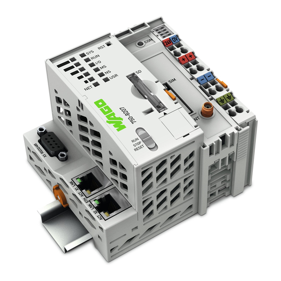
WAGO 750-8207 Manual (410 pages)
PFC200 CS 2ETH RS 3G PLC - Controller PFC200
Brand:
WAGO
| Category:
I/O Systems
| Size: 5.12 MB
Table of Contents
Table of Contents
3
Table of Contents
7
Table of Contents
9
Notes about this Documentation
15
Validity of this Documentation
15
Copyright
15
Table 1: Variants
15
Symbols
16
Number Notation
18
Font Conventions
18
Table 2: Number Notation
18
Table 3: Font Conventions
18
Important Notes
19
Legal Bases
19
Subject to Changes
19
Personnel Qualifications
19
Use of the WAGO-I/O-SYSTEM 750 in Compliance with Underlying Provisions
19
Technical Condition of Specified Devices
20
Safety Advice (Precautions)
21
Disclaimer
22
Licensing Terms of the Software Package Used
23
Special Use Conditions for ETHERNET Devices
23
Device Description
24
View
27
Figure 1: View of Device
27
Table 4: Legend for Figure "View
27
Labeling
29
Manufacturing Number
29
Figure 2: Marking Area for Serial Numbers
29
Connectors
30
Data Contacts/Internal Bus
30
Figure 3: Data Contacts
30
Power Jumper Contacts/Field Supply
31
Figure 4: Power Jumper Contacts
31
Table 5: Legend for Figure "Power Jumper Contacts
31
CAGE CLAMP ® Connectors
32
Figure 5: CAGE CLAMP ® Connections
32
Table 6: Legend for Figure "CAGE CLAMP ® Connections
32
Service Interface
33
Figure 6: Service Interface (Closed and Open Flap)
33
Table 7: Service Interface
33
Network Connections - X1, X2
34
Figure 7: Network Connections - X1, X2
34
Table 8: Legend for Figure "Network Connections - X1, X2
34
RS-232/RS-485 - X3 Communication Connection
35
Figure 8: RS-232/RS-485 - X3 Communication Connection
35
Table 9: Legend for Figure "RS-232/RS-485 - X3 Communication Connection
35
Operating as an RS-232 Interface
36
Figure 9: Termination with DTE-DCE Connection (1:1)
36
Figure 10: Termination with DTE-DTE Connection (Cross-Over)
36
Table 10: Function of RS-232 Signals for DTE/DCE
36
Operating as an RS-485 Interface
37
Figure 11: RS-485 Bus Termination
37
Mobile Radio Antenna
38
Figure 12: Mobile Radio Antenna Connection
38
Display Elements
39
Power Supply Indicating Elements
39
Figure 13: Power Supply Indicating Elements
39
Table 11: Legend for Figure "Power Supply Indicating Elements
39
Fieldbus/System Indicating Elements
40
Figure 14: Indicating Elements for Fieldbus/System
40
Table 12: Legend for Figure "Fieldbus/System Indicating Elements
40
Memory Card Indicating Elements
41
Figure 15: Indicating Elements, Memory Card Slot
41
Table 13: Legend for Figure "Indicating Elements, Memory Card Slot
41
Network Indicating Elements
42
Figure 16: Indicating Elements, RJ-45 Jacks
42
Table 14: Legend for Figure "Indicating Elements, RJ-45 Jacks
42
Mobile Radio Network Status Indicators
43
Figure 17: Mobile Radio Network Status Indicators
43
Table 15: Legend for the "Mobile Radio Network Status Indicators" Figure
43
Operating Elements
44
Operating Mode Switch
44
CODESYS 2 Runtime System
44
E!Runtime Runtime System
44
Figure 18: Mode Selector Switch
44
Table 16: Mode Selector Switch
44
Table 17: Mode Selector Switch
44
Reset Button
45
Figure 19: Reset Button
45
Slot for Memory Card
46
Figure 20: Slot for SD Memory Card
46
SIM Card Slot
47
Figure 21: SIM Card Slot
47
Table 18: Legend for Figure "SIM Card Slot
47
Schematic Diagram
48
Figure 22: Schematic Diagram
48
Technical Data
49
Device Data
49
System Data
49
Power Supply
49
Table 19: Technical Data − Device Data
49
Table 20: Technical Data - System Data
49
Table 21: Technical Data - Power Supply
49
Clock
50
Programming
50
Internal Data Bus
50
Table 22: Technical Data - Clock
50
Table 23: Technical Data - Programming
50
Table 24: Technical Data - Internal Data Bus
50
Ethernet
51
Serial Interface
51
Mobile Radio Modem
51
Connection Type
51
Table 25: Technical Data - ETHERNET
51
Table 26: Technical Data - Serial Interface
51
Table 27: Technical Data - Mobile Radio Modem
51
Table 28: Technical Data - Field Wiring
51
Climatic Environmental Conditions
52
Table 29: Technical Data - Power Jumper Contacts
52
Table 30: Technical Data - Data Contacts
52
Table 31: Technical Data - Climatic Environmental Conditions
52
Approvals
53
Standards and Guidelines
53
Function Description
55
Network
55
Interface Configuration
55
Operation in Switch Mode
55
Operation with Separate Network Interfaces
55
Network Security
56
Users and Passwords
56
Services and Users
56
WBM User Group
57
Linux ® User Group
57
SNMP User Group
57
Table 32: WBM Users
57
Table 33: Linux ® Users
57
Web Protocols for WBM Access
58
TLS Encryption
58
Network Configuration
60
Host Name/Domain Name
60
Default Gateways
60
Network Services
62
DHCP Client
62
DHCP Server
62
Table 34: List of Parameters Transmitted Via DHCP
63
DNS Server
64
Memory Card Function
65
Formatting
65
Data Backup
67
Backup Function
67
Restore Function
68
Inserting a Memory Card During Operation
70
Removing the Memory Card During Operation
70
Setting the Home Directory for the Runtime System
71
Mounting
72
Installation Position
72
Overall Configuration
72
Mounting Onto Carrier Rail
74
Carrier Rail Properties
74
WAGO DIN Rails
75
Spacing
75
Figure 23: Spacing
75
Table 35: WAGO DIN Rails
75
Mounting Sequence
76
Inserting Devices
77
Figure 24: Release Tab of Controller
77
Inserting the Controller
77
Figure 25: Insert I/O Module (Example)
78
Figure 26: Snap the I/O Module into Place (Example)
78
Inserting the I/O Module
78
Connect Devices
79
Connecting a Conductor to the CAGE CLAMP
79
Figure 27: Connecting a Conductor to a CAGE CLAMP
79
Power Supply Concept
80
Figure 28: Fuse Protection of the Electronic Circuit Power Supply
80
Fuse Protection of the Electronic Circuit Power Supply
80
Figure 29: Power Supply Concept
81
Supplementary Power Supply Regulations
81
Table 36: Filter Modules for 24 V Supply
81
Commissioning
82
Switching on the Controller
82
Determining the IP Address of the Host PC
83
Setting an IP Address
84
Table 37: Default IP Addresses for ETHERNET Interfaces
84
Table 38: Network Mask 255.255.255.0
84
Assigning an IP Address Using DHCP
85
Figure 30: "Open DHCP", Example Figure
85
Changing an IP Address Using the "CBM" Configuration Tool Via the Serial Interface
86
Figure 31: CBM Starting Screen
86
Figure 32: CBM - Selecting "Networking
87
Figure 33: CBM - Selecting "TCP/IP
87
Figure 34: CBM - Selecting "IP Address
87
Figure 35: CBM - Selecting the IP Address
88
Figure 36: CBM - Entering a New IP Address
88
Changing an IP Address Using "WAGO Ethernet Settings
89
Figure 37: "WAGO Ethernet Settings" - Starting Screen (Example)
89
Figure 38: "WAGO Ethernet Settings" - "Network" Tab
90
Temporarily Setting a Fixed IP Address
91
Testing the Network Connection
92
Figure 39: Example of a Function Test
92
Changing Standard Passwords
93
Shutdown/Restart
94
Initiating Reset Functions
95
CODESYS 2 Runtime System
95
Cold Start Reset
95
E!Runtime Runtime System
95
Warm Start Reset
95
Software Reset
96
Configuration
97
Configuration Via Web-Based-Management (WBM)
98
Figure 40: Entering Authentication
99
WBM User Administration
99
Figure 41: Password Reminder
100
Table 39: User Settings in the Default State
100
Table 40: Access Rights for WBM Pages
100
Figure 42: WBM Browser Window (Example)
102
Figure 43: WBM Status Information (Example)
102
General Information about the Page
102
Status Information" Page
105
Controller Details" Group
105
Network Details (Xn)" Group(S)
105
Table 41: WBM "Status Information" Page - "Controller Details" Group
105
Table 42: WBM "Status Information Page - "Network Details (Xn)" Group(S)
105
General PLC Runtime Configuration" Page
106
General PLC Runtime Configuration" Group
106
Table 43: WBM "General PLC Runtime Configuration" Page - "General PLC
106
PLC Runtime Information" Page
108
PLC Runtime" Group
108
Project Details" Group
108
Table 44: WBM "PLC Runtime Information" Page - "PLC Runtime" Group
108
Table 45: WBM "PLC Runtime Information" Page - "Project Details" Group
108
Task N" Group(S)
109
Table 46: WBM "PLC Runtime Information" Page - "Task N" Group(S)
109
PLC Webvisu" Page
110
Web Server Configuration" Group
110
Table 47: WBM "PLC Webvisu" Page - "Web Server Configuration" Group
110
Configuration of Host and Domain Name" Page
111
Hostname" Group
111
Domain Name" Group
111
Table 48: WBM "Configuration of Host and Domain Name" Page - "Hostname
111
Table 49: WBM "Configuration of Host and Domain Name" Page - "Domain
111
TCP/IP Configuration" Page
112
IP Configuration (Xn)" Group(S)
112
Table 50: WBM "TCP/IP Configuration" Page - "IP Configuration (Xn)" Group(S)
112
Default Gateway N" Groups
113
Table 51: WBM "TCP/IP Configuration" Page - "Default Gateway N" Group
113
DNS Server" Group
114
Table 52: WBM "TCP/IP Configuration" Page - "DNS Server" Group
114
Ethernet Configuration" Page
115
Switch Configuration" Group
115
Interface Xn" Groups
115
Table 53: WBM "Ethernet Configuration" Page - "Switch Configuration" Group
115
Table 54: WBM "Ethernet Configuration" Page - "Interface Xn" Groups
116
General Firewall Configuration" Page
117
Global Firewall Parameters" Group
117
Table 55: WBM "General Firewall Configuration" Page - "Global Firewall
117
Firewall Parameters Interface XXX" Group
118
Table 56: WBM "General Firewall Configuration" Page - "Firewall Parameter
118
Configuration of MAC Address Filter" Page
119
Global MAC Address Filter State" Group
119
Table 57: WBM "Configuration of MAC Address Filter" Page - "Global MAC
119
MAC Address Filter State Xn" Group
120
MAC Address Filter Whitelist" Group
120
Table 58: WBM "Configuration of MAC Address Filter" Page - "MAC Address
120
Table 59: WBM "Configuration of MAC Address Filter" Page - "MAC Address
120
Configuration of User Filter" Page
121
User Filter" Group
121
User Filter N" Group
121
Table 60: WBM "Configuration of User Filter" Page - "User Filter" Group
121
Table 61: WBM "Configuration of User Filter" Page - "User Filter N" Group
121
Add New User Filter" Group
122
Table 62: WBM "Configuration of User Filter" Page - "Add New User Filter
122
Configuration of Time and Date" Page
123
Date on Device" Group
123
Time on Device" Group
123
Table 63: WBM "Configuration of Time and Date" Page - "Date on Device" Group
123
Table 64: WBM "Configuration of Time and Date" Page - "Time on Device
123
Time Zone" Group
124
Table 65: WBM "Configuration of Time and Date" Page - "Time Zone" Group
124
TZ String" Group
125
Table 66: WBM "Configuration of Time and Date" Page - "TZ String" Group
125
Change Password for Selected User" Group
126
Table 67: WBM "Configuration of the Users for the Web-Based Management" Page - "Change Password for Selected User" Group
126
Create Bootable Image" Page
127
Create Bootable Image from Active Partition
127
Table 68: WBM "Create Bootable Image" Page - "Create Bootable Image from Active Partition" Group
127
Configuration of Serial Interface RS232" Page
129
Serial Interface Assigned To" Group
129
Assign Owner of Serial Interface (Active after Next Controller Reboot)" Group
129
Table 69: WBM "Configuration of Serial Interface RS232" Page - "Assign Owner
129
Configuration of Service Interface" Page
130
Service Interface Assigned To" Group
130
Assign Owner of Service Interface (Enabled after Next Controller Reboot)" Group
130
Table 70: WBM "Configuration of Serial Interface RS-232" Page - "Assign Owner
130
Reboot Controller" Page
131
Reboot Controller" Group
131
Firmware Backup" Page
132
Table 71: "Firmware-Backup" WBM Page
132
Firmware Restore" Page
134
Table 72: "Firmware Restore" WBM Page
134
System Partition" Page
136
Current Active Partition" Group
136
Set Inactive Partition Active" Group
136
Mass Storage" Page
137
Device Name>" Group(S)
137
Device Name> - FAT Format" Group(S)
137
Table 73: WBM "Mass Storage" Page - "<Device Name>" Group
137
Table 74: WBM "Mass Storage" Page - "<Device Name>" Group
137
Software Uploads" Page
138
Upload New Software" Group
138
Activate New Software" Group
138
Table 75: WBM "Software Uploads" Page - "Upload New Software" Group
138
Table 76: WBM "Software Uploads" Page - "Activate New Software" Group
138
Configuration of Network Services" Page
139
Telnet" Group
139
FTP" Group
139
FTPS" Group
139
HTTP" Group
139
Table 77: WBM "Configuration of Network Services" Page - "Telnet" Group
139
Table 78: WBM "Configuration of Network Services" Page - "FTP" Group
139
Table 79: WBM "Configuration of Network Services" Page - "FTPS" Group
139
Table 80: WBM "Configuration of Network Services" Page - "HTTP" Group
139
HTTPS" Group
140
I/O-CHECK" Group
140
Table 81: WBM "Configuration of Network Services" Page - "HTTPS" Group
140
Table 82: WBM "Configuration of Network Services" Page - "I/O-CHECK" Group
140
Configuration of NTP Client" Page
141
NTP Client Configuration" Group
141
NTP Single Request" Group
141
Table 83: WBM "Configuration of NTP Client" Page - "NTP Client Configuration
141
Configuration of PLC Runtime Services" Page
142
General Configuration" Group
142
CODESYS 2" Group
142
E!Runtime" Group
142
Table 84: WBM "Configuration of PLC Runtime Services" Page - "General
142
Table 85: WBM "Configuration of CODESYS Services" Page - "CODESYS
142
Table 86: WBM "Configuration of CODESYS Services" Page - "E!Runtime Web
142
SSH Server Settings" Page
144
SSH Server" Group
144
Table 87: WBM "SSH Server Settings" Page - "SSH Server" Group
144
TFTP Server" Page
145
TFTP Server" Group
145
Table 88: WBM "TFTP Server" Page - "TFTP Server" Group
145
DHCP Configuration" Page
146
DHCP Configuration Xn" Group
146
Table 89: WBM "DHCP Configuration" - "DHCP Configuration Xn" Group
146
Configuration of DNS Service" Page
147
DNS Service" Group
147
Table 90: WBM "Configuration of DNS Service" Page - "DNS Service" Group
147
MODBUS Services Configuration" Page
148
MODBUS TCP" Group
148
MODBUS UDP" Group
148
Table 91: WBM "MODBUS Services Configuration" Page - "MODBUS TCP
148
Table 92: WBM "MODBUS Configuration Services" Page - "MODBUS UDP
148
Configuration of General SNMP Parameters" Page
149
General SNMP Configuration" Group
149
Table 93: WBM "Configuration of General SNMP Parameters" Page - "General
149
Configuration of SNMP V1/V2C Parameters" Page
150
SNMP V1/V2C Manager Configuration" Group
150
Actually Configured Trap Receivers" Group(S)
150
Table 94: WBM "Configuration of SNMP V1/V2C Parameters" Page - "SNMP
150
Table 95: WBM "Configuration of SNMP V1/V2C Parameters" Page - "Actually
150
Trap Receiver N" Group(S)
151
Add New Trap Receiver" Group
151
Table 96: WBM "Configuration of SNMP V1/V2C Parameters" Page - "Trap
151
Table 97: WBM "Configuration of SNMP V1/V2C Parameters" Page - "Add New
151
Configuration of SNMP V3 Users" Page
152
Actually Configured V3 Users" Group(S)
152
V3 User N" Group(S)
152
Table 98: WBM "Configuration of SNMP V3" Page - "Actually Configured V3
152
Table 99: WBM "Configuration of SNMP V3 Users" Page - "V3 User N" Group(S)
152
Add New V3 User" Group
153
Table 100: WBM "Configuration of SNMP V3 Users" Page - "Add New V3 User
153
Diagnostic Information" Page
154
Table 101: WBM "Diagnostic Information" Page
154
Configuration of Internal 3G Modem" Page
155
SIM Authentication" Group
155
Table 102: WBM "Configuration of Internal 3G Modem" Page - "SIM
155
Mobile Network Configuration" Group
156
Table 103: WBM "Configuration of Internal 3G Modem" Page - "Mobile Network
156
Provider List" Group
157
Network Package Service" Group
157
Table 104: WBM "Configuration of Internal 3G Modem" Page - "Provider List
157
Table 105: WBM "Configuration of Internal 3G Modem" Page - "Network
157
Upload and Activate New Modem Software" Group
158
Table 106: WBM "Configuration of Internal 3G Modem" Page - "Upload and Activate New Modem Software" Group
158
Configuration of Openvpn and Ipsec" Page
159
Openvpn" Group
159
Ipsec" Group
159
Table 107: WBM "Configuration of Openvpn and Ipsec" Page - "Openvpn
159
Table 108: WBM "Configuration of Openvpn and Ipsec" Page - "Ipsec" Group
159
Certificate Upload" Group
160
Certificate List" Group
160
Private Key List" Group
160
Table 109: WBM "Configuration of Openvpn and Ipsec" Page - "Certificate
160
Table 110: WBM "Configuration of Openvpn and Ipsec" Page - "Certificate List
160
Table 111: WBM "Configuration of Openvpn and Ipsec" Page - "Private Key
160
Security Settings" Page
161
TLS Configuration" Group
161
Table 112: "Security Settings" WBM Page - "TLS Configuration" Group
161
Open Source Licenses" Page
162
WAGO Licenses" Page
163
Configuration Using a Terminal Program (CBM)
164
CBM Menu Structure Overview
164
Figure 44: CBM Main Menu (Example)
164
Table 113: CBM Menu Structure
164
Information" Menu
167
Information" > "Controller Details" Submenu
167
Table 114: "Information" Menu
167
Table 115: "Information" > "Controller Details" Submenu
167
Information" > "Network Details" Submenu
168
Table 116: "Information" > "Network Details" Submenu
168
PLC Runtime" Menu
169
PLC Runtime" > "Information" Submenu
169
Table 117: "PLC Runtime" Menu
169
Table 118: "PLC Runtime" > "Information" Submenu
169
Information" > "Runtime Version" Submenu
170
Information" > "Webserver Version" Submenu
170
Information" > "State" Submenu
170
Table 119: "PLC Runtime" > "Information" > "Runtime Version" Submenu
170
Table 120: "PLC Runtime" > "Information" > "Webserver Version" Submenu
170
Table 121: "PLC Runtime" > "Information" > "State" Submenu
170
Information" > "Number of Tasks" Submenu
171
Information" > "Project Details" Submenu
171
Information" > "Tasks" Submenu
171
Table 122: "PLC Runtime" > "Information" > "Number of Tasks" Submenu
171
Table 123: "PLC Runtime" > "Information" > "Project Details" Submenu
171
Table 124: "PLC Runtime" > "Information" > "Tasks" Submenu
171
Tasks" > "Task N" Submenu
172
PLC Runtime" > "General Configuration" Submenu
172
Table 125: "PLC Runtime" > "Information" > "Tasks" > "Task N" Submenu
172
Table 126: "PLC Runtime" > "General Configuration" Submenu
172
General Configuration" > "PLC Runtime Version" Submenu
173
General Configuration" > "Home dir on SD Card" Submenu173
173
Table 127: "PLC Runtime" > "General Configuration" > "PLC Runtime Version
173
Table 128: "PLC Runtime" > "General Configuration" > "Home dir on SD Card
173
PLC Runtime" > "Webvisu" Submenu
174
Table 129: "PLC Runtime" > "Webvisu" Submenu
174
Networking" Menu
175
Networking" > "Host/Domain Name" Submenu
175
Table 130: "Networking" Menu
175
Table 131: "Networking" > "Host/Domain Name" Submenu
175
Host/Domain Name" > "Hostname" Submenu
176
Host/Domain Name" > "Domain Name" Submenu
176
Networking" > "TCP/IP" Submenu
176
Table 132: "Networking" > "Hostname" Submenu
176
Table 133: "Networking" > "Host/Domain Name" > "Domain Name" Submenu
176
Table 134: "Networking" > "TCP/IP" Submenu
176
TCP/IP" > "IP Address" Submenu
177
IP Address" > "Xn" Submenu
177
Table 135: "Networking" > "IP Address" Submenu
177
Table 136: "Networking" > "TCP/IP" > "IP Address" Submenu > "Xn
177
TCP/IP" > "Default Gateway" Submenu
178
Default Gateway" > "Default Gateway N" Submenu
178
Table 137: "Networking" > "TCP/IP" > "Default Gateway" Submenu
178
Table 138: "Networking" > "TCP/IP" > "Default Gateway" > "Default Gateway N
178
TCP/IP" > "DNS Server" Submenu
179
Networking" > "Ethernet" Submenu
179
Table 139: "Networking" > "TCP/IP" > "DNS Server" Submenu
179
Table 140: "Networking" > "Ethernet" Submenu
179
Ethernet" > "Switch Configuration" Submenu
180
Ethernet" > "Ethernet Ports" Submenu
180
Table 141: "Networking" > "Ethernet" > "Switch Configuration" Submenu
180
Table 142: "Networking" > "Ethernet" > "Ethernet Ports" Submenu
180
Ethernet Ports" > "Interface Xn" Submenu
181
Table 143: "Networking" > "Ethernet" > "Ethernet Ports" > "Interface Xn
181
Firewall" Menu
182
Table 144: "Firewall" Menu
182
Firewall" > "General Configuration" Submenu
183
Table 145: "Firewall" > "General Configuration" Submenu
183
General Configuration" > "Interface XXX" Submenu
184
Table 146: "Firewall" > "General Configuration" > "Interface XXX" Submenu
184
Firewall" > "MAC Address Filter" Submenu
186
Table 147: "Firewall" > "MAC Address Filter" Submenu
186
MAC Address Filter" > "MAC Address Filter Whitelist" Submenu187
187
MAC Address Filter Whitelist" > "Add New / no (N)" Submenu
187
Table 148: "Firewall" > "MAC Address Filter" > "MAC Address Filter Whitelist
187
Table 149: "Firewall" > "MAC Address Filter" > "MAC Address Filter Whitelist
187
Firewall" > "User Filter" Submenu
188
Table 150: "Firewall" > "User Filter" Submenu
188
User Filter" > "Add New / no (N)" Submenu
189
Table 151: "Firewall" > "User Filter" > "Add New / no (N)" Submenu
189
Clock" Menu
190
Table 152: "Clock" Menu
190
Administration" Menu
191
Table 153: "Administration" Menu
191
Administration" > "Create Image" Submenu
192
Administration" > "Users" Submenu
192
Table 154: "Administration" > "Create Image" Submenu
192
Table 155: "Administration" > "Users" Submenu
192
Package Server" Menu
193
Package Server" > "Firmware Backup" Submenu
193
Table 156: "Package Server" Menu
193
Table 157: "Package Server" > "Firmware Backup" Menu
193
Firmware Backup" > "Auto Update Feature" Submenu
194
Firmware Backup" > "Destination" Submenu
194
Table 158: "Package Server" > "Firmware Backup" > "Auto Update Feature
194
Table 159: "Package Server" > "Firmware Backup" > "Auto Update Feature
194
Package Server" > "Firmware Restore" Submenu
195
Firmware Restore" > "Select Package" Submenu
195
Table 160: "Package Server" > "Firmware Restore" Menu
195
Table 161: "Package Server" > "Firmware Restore" > "Select Package" Menu
195
Package Server" > "System Partition" Submenu
196
Table 162: "Package Server" > "System Partition" Submenu
196
Mass Storage" Menu
197
Mass Storage" > "SD Card" Submenu
197
Table 163: "Mass Storage" Menu
197
Table 164: "Mass Storage" > "SD Card" Menu
197
Software Uploads" Menu
198
Ports and Services" Menu
199
Table 165: "Ports and Services" Menu
199
Ports and Services" > "Telnet" Submenu
200
Ports and Services" > "FTP" Submenu
200
Table 166: "Ports and Services" > "Telnet" Submenu
200
Table 167: "Ports and Services" > "FTP" Submenu
200
Ports and Services" > "FTPS" Submenu
201
Ports and Services" > "HTTP" Submenu
201
Table 168: "Ports and Services" > "FTPS" Submenu
201
Table 169: "Ports and Services" > "HTTP" Submenu
201
Ports and Services" > "HTTPS" Submenu
202
Ports and Services" > "NTP" Submenu
202
Table 170: "Ports and Services" > "HTTPS" Submenu
202
Table 171: "Ports and Services" > "NTP" Submenu
202
Ports and Services" > "SSH" Submenu
203
Ports and Services" > "TFTP" Submenu
203
Table 172: "Ports and Services" > "SSH" Submenu
203
Table 173: "Ports and Services" > "TFTP" Submenu
203
Ports and Services" > "DHCPD" Submenu
204
DHCPD" > "Xn" Submenu
204
Table 174: "Ports and Services" > "DHCPD" Submenu
204
Table 175: "Ports and Services" > "DHCPD" > "Xn" Submenu
204
Ports and Services" > "DNS" Submenu
205
Table 176: "Ports and Services" > "DNS" Submenu
205
Ports and Services" > "IOCHECK PORT" Submenu
206
Ports and Services" > "Modbus TCP" Submenu
206
Table 177: "Ports and Services" > "IOCHECK PORT" Submenu
206
Table 178: "Ports and Services" > "Modbus TCP" Submenu
206
Ports and Services" > "Modbus UDP" Submenu
207
Ports and Services" > "PLC Runtime Services" Submenu
207
Table 179: "Ports and Services" > "Modbus UDP" Submenu
207
Table 180: "Ports and Services" > "PLC Runtime Services" Submenu
207
PLC Runtime Services" > "CODESYS 2" Submenu
208
Table 181: "Ports and Services" > "PLC Runtime Services" > "CODESYS
208
PLC Runtime Services" > "E!Runtime" Submenu
209
Table 182: "Ports and Services" > "PLC Runtime Services" > "E!Runtime
209
Firewall Status" Submenu
210
Table 183: "Ports and Services" > "Firewall Status" Submenu
210
SNMP" Menu
211
SNMP" > "General SNMP Configuration" Submenu
211
Table 184: "SNMP" Menu
211
Table 185: "SNMP" > "General SNMP Configuration" Submenu
211
SNMP" > "SNMP V1/V2C Manager Configuration" Submenu
212
SNMP" > "SNMP V1/V2C Trap Receiver Configuration" Submenu
212
Table 186: "SNMP" > "SNMP V1/V2C Manager Configuration" Submenu
212
Table 187: "SNMP" > "SNMP V1/V2C Trap Receiver Configuration" Submenu
212
SNMP" > "SNMP V3 Configuration" Submenu
213
Table 188: "SNMP" > "SNMP V3 Configuration" Submenu
213
SNMP" > "(Secure)Snmp Firewalling" Submenu
214
Table 189: "SNMP" > "(Secure )SNMP Firewalling" Submenu
214
Configuration Using "WAGO ETHERNET Settings
215
Figure 45: "WAGO ETHERNET Settings" - Start Screen
215
Figure 46: "WAGO ETHERNET Settings" - Communication Link
216
Identification Tab
217
Figure 47: "WAGO ETHERNET Settings" - Identification Tab (Example)
217
Network Tab
218
Figure 48: "WAGO ETHERNET Settings" - Network Tab
218
Protocol Tab
220
Figure 49: "WAGO ETHERNET Settings" - Protocol Tab
220
Status Tab
221
Figure 50: "WAGO ETHERNET Settings" - Status Tab
221
Run-Time System CODESYS 2.3
222
Installing the CODESYS 2.3 Programming System
222
First Program with CODESYS 2.3
222
Start the CODESYS Programming System
222
Creating a Project and Selecting the Target System
222
Figure 51: Target System Settings (1)
223
Figure 52: Target System Settings (2)
223
Creating the PLC Configuration
224
Figure 53: Creating a New Function Block
224
Figure 54: Programming Interface with the PLC_PRG Program Module
224
Figure 55: "Resources" Tab
225
Figure 56: Control Configuration - Edit
226
Figure 57: "Start WAGO-I/O-CHECK and Scan" Button
226
Figure 58: WAGO-I/O-CHECK - Starting Screen
227
Figure 59: I/O Configurator Empty
228
Figure 60: "Add I/O Modules" Button
228
Figure 61: "Module Selection" Window
229
Figure 62: I/O Configurator with Defined I/O Modules
229
Figure 63: Variable Declaration
230
Figure 64: Control Configuration: I/O Modules with Their Associated Addresses
230
Editing the Program Function Block
231
Figure 65: Program Function Block
231
Figure 66: Input Assistant for Selecting Variables
231
Figure 67: Example of an Allocation
232
Loading and Running the PLC Program in the Fieldbus Controller (ETHERNET)
233
Figure 68: Creating a Communication Link - Step 1
233
Figure 69: Creating a Communication Link - Step 2
234
Figure 70: Creating a Communication Link - Step 3
234
Creating a Boot Project
235
Syntax of Logical Addresses
235
Table 190: Syntax of Logical Addresses
235
Creating Tasks
236
Figure 71: Task Configuration
236
Figure 72: Changing Task Names 1
237
Figure 73: Call-Up to Add to the Program Module
238
Cyclic Tasks
239
Figure 74: Cyclic Task
239
Freewheeling Tasks
240
Debugging an IEC Program
240
Figure 75: Freewheeling Task
240
Figure 76: Debugging (Case 1)
241
Figure 77: Debugging (Case 2)
241
Figure 78: Debugging (Case 3)
242
Figure 79: Debugging (Case 4)
242
Figure 80: Debugging (Case 5)
243
Figure 81: Debugging (Case 6)
243
System Events
244
Figure 82: Debugging (Case 7)
244
Figure 83: CODESYS - System Events
245
Table 191: Events
246
Creating an Event Handler
247
Figure 84: CODESYS Program Provokes Division by "0
247
Figure 85: CODESYS - Creating and Activating an Event Handler
247
Figure 86: CODESYS - New Module Has Been Generated
248
Figure 87: CODESYS - Enter the Event in a Global Variable
248
Process Images
249
Figure 88: CODESYS - Variable Contents Prior to Division by "0
249
Figure 89: CODESYS - Variable Contents after Division by "0" and Call-Up of the
249
Figure 90: Process Image
250
Process Images for I/O Modules Connected to the Controller
251
Figure 91: Flag Area
251
Process Image for Slaves Connected to the Fieldbus
252
Access to Process Images of the Input and Output Data Via CODESYS
252
Table 192: Access to the Process Images of the Input and Output Data - Internal Data Bus
252
Table 193: Access to the Process Images of the Input and Output Data - MODBUS
253
Table 194: Access to the Process Images of the Input and Output Data - Canopen
253
Table 195: Access to the Process Images of the Input and Output Data - PROFIBUS
253
Addressing Example
254
Table 196: Access to the Process Images of the Input and Output Data - Flags
254
Table 197: Arrangement of the I/O Modules for the Addressing Example
254
Table 198: Addressing Example
254
Internal Data Bus Synchronization
255
Case 1: CODESYS Task Interval Set Smaller than the I/O Module Cycle
255
Figure 92: Internal Data Bus Synchronization 01
256
Case 2: CODESYS Task Interval Smaller than Twice the Internal Data Bus Cycle
257
Figure 93: I/O Module Synchronization 02
257
Case 3: CODESYS Task Interval Greater than Twice the Internal Data Bus Cycle
258
Figure 94: I/O Module Synchronization 03
258
Case 4: CODESYS Task Interval Greater than 10 Ms
259
Figure 95: Internal Data Bus Synchronization 04
259
Internal Data Bus Configuration
260
Figure 96: Internal Data Bus Settings
260
Effect of Update Mode on CODESYS Tasks
261
Asynchronous Update Mode
261
Table 199: Internal Data Bus Settings
261
Synchronous Update Mode
262
Memory Settings in CODESYS
262
Program Memory
262
Figure 97: Program Memory (Example)
263
Data Memory and Function Block Limitation
264
Figure 98: Data Memory and Function Block Limitation (Example)
264
Remanent Memory
265
Figure 99: Remanent Main Memory (Example)
265
Figure 100: Flag and Retain Memory (Example)
265
General Target System Settings
266
CODESYS Visualization
266
Figure 101: General Target System Settings
266
Figure 102: Selecting the Visualization Technique in the Target System Settings
267
Figure 103: Creating the PLC_VISU Starting Visualization
268
Limits of CODESYS Visualization
269
Eliminating Errors in CODESYS Web Visualization
271
Table 200: Errors and Remedies
271
Faqs about CODESYS Web Visualization
272
E!Runtime Runtime Environment
274
General Notes
274
CODESYS V3 Priorities
275
Table 201: CODESYS V3 Priorities
275
Memory Spaces under E!Runtime
276
Program and Data Memory
276
Function Block Limitation
276
Remanent Memory
276
Figure 104: Remanent Main Memory
276
Modbus - Codesys 2
277
General
277
Features
277
Configuration
278
Figure 105: CODESYS PLC Configuration - MODBUS Settings
278
MODBUS Settings
279
Table 202: MODBUS Settings
279
MODBUS TCP Settings
280
MODBUS UDP Settings
280
MODBUS RTU Settings
280
Table 203: MODBUS TCP Settings
280
Table 204: MODBUS UDP Settings
280
Table 205: MODBUS RTU Settings
281
Data Exchange
283
Process Image
284
Figure 106: MODBUS Process Image
284
Flag Area
285
Figure 107: Flag Area
285
MODBUS Registers
286
MODBUS Mapping
286
MODBUS Mapping for Write Bit Services FC1, FC2
286
Table 206: MODBUS Mapping for Read Bit Services FC1, FC2
286
MODBUS Mapping for Write Bit Services FC5, FC15
287
Table 207: MODBUS Mapping for Write Bit Services FC5, FC15
287
Table 208: MODBUS Mapping for Read Register Services FC3, FC4, FC23
289
MODBUS Mapping for Write Register Services FC6, FC16, FC22, FC23
290
Table 209: MODBUS Mapping for Write Register Services FC6, FC16, FC22
291
WAGO MODBUS Registers
292
Table 210: WAGO MODBUS Registers
292
Process Image Properties
293
Register 0X1022 - Number of Registers in the MODBUS Input Process Image
293
Register 0X1023 - Number of Registers in the MODBUS Output Process Image
293
Register 0X1024 - Number of Bits in the MODBUS Input Process Image
293
Register 0X1025 - Number of Bits in the MODBUS Output Process Image
293
Network Configuration
294
Register 0X1028 - IP Configuration
294
Register 0X102A - Number of Established TCP Connections
294
Register 0X1030 - MODBUS TCP Socket Timeout
294
Register 0X1031 - MAC Address for ETHERNET-Interface 1 (Eth0)294
294
Register 0X1037 - MODBUS TCP Response Delay
294
PLC Status Register
295
MODBUS Watchdog
295
Figure 108: State Diagram, STANDARD_WATCHDOG Operation Mode
295
Figure 109: State Diagram, ALTERNATIVE_WATCHDOG Operation Mode
296
Register 0X1100 - Watchdog Command
297
Figure 110: State Diagram, Switchover Operation Mode
297
Table 211: Watchdog Commands
298
Register 0X1101 - Watchdog Status
299
Register 0X1102 - Watchdog Timeout
299
Register 0X1103 - Watchdog Config
299
Table 212: Watchdog Status
299
Register 0X1104 - Watchdog Operation Mode
300
Table 213: Watchdog Configuration
300
MODBUS Constants Registers
301
Electronic Nameplate
301
Register 0X2010 - Revision (Firmware Index)
301
Register 0X2011 - Series Designator
301
Register 0X2012 - Device ID
301
Table 214: Watchdog Operation Modes
301
Register 0X2013 - Major Firmware Version
302
Register 0X2014 - Minor Firmware Version
302
Register 0X2015 - MBS Version
302
Diagnostics
303
Diagnostics for the MODBUS Master
303
Diagnostics for the Runtime System
303
Diagnostics for the Error Server
303
Table 215: Diagnostics for the Error Server
303
MODBUS - E!Runtime
306
MODBUS Address Overview
306
Figure 111: MODBUS Address Overview
306
MODBUS Registers
307
Table 216: WAGO MODBUS Registers
307
MODBUS Watchdog
309
Figure 112: State Diagram, ADVANCED_WATCHDOG Operation Mode
309
Figure 113: State Diagram, SIMPLE_WATCHDOG Operation Mode
310
Figure 114: State Diagram, Switching Operation Modes
310
Register 0Xfa00 - Watchdog Command
311
Table 217: Watchdog Commands
311
Register 0Xfa01 - Watchdog Timeout
312
Register 0Xfa02 - Watchdog Status
312
Table 218: Watchdog Status
312
Register 0Xfa03 - Watchdog Config
313
Table 219: Watchdog Configuration
313
MODBUS TCP Connection Watchdog Register
314
Status Registers
315
PLC Status Register
315
Electronic Nameplate
315
Order Number
315
Firmware Version
315
Hardware Version
315
Firmware Loader/Boot Loader
315
MODBUS Process Image Version
315
MODBUS Process Image Registers
315
Constant Registers
316
Live Register
316
Estimating the MODBUS Master CPU Load
317
Diagnostics
318
Operating and Status Messages
318
Power Supply Indicating Elements
318
Figure 115: Power Supply Indicating Elements
318
Table 220: Legend for Figure "Power Supply Indicating Elements
318
Table 221: Field-Side Supply Diagnostics
318
Table 222: System Power Supply Diagnistics
318
Mobile Radio Network Status Indicators
319
Figure 116: Mobile Radio Network Status Indicators
319
Table 223: Legend for the "Mobile Radio Network Status Indicators" Figure
319
Table 224: Diagnostics Via con LED
319
Fieldbus/System Indicating Elements
320
Figure 117: Indicating Elements for Fieldbus/System
320
Table 225: Diagnostics Via SYS LED
320
Table 226: Diagnostics RUN LED
321
Table 227: RUN LED Diagnostics - E!Runtime
322
Table 228: Diagnostics I/O LED
323
Table 229: MS-LED Diagnostics
324
Table 230: Diagnostics Via NET LED
325
Table 231: Diagnostics Via Signal Quality Leds
326
Table 232: Signal Quality Meaning
326
Diagnostics Messages Via Flashing Sequences
327
Flashing Sequences
327
Figure 118: Flashing Sequence Process Diagram
328
Example of a Diagnostics Message Indicated by a Flashing Sequence
329
Meaning of Blink Codes and Procedures for Troubleshooting
330
Table 233: Overview of Error Codes, I/O LED
330
Table 234: Error Code 1, Explanation of Blink Codes and Procedures for Troubleshooting
331
Table 235: Error Code 2, Explanation of Blink Codes and Procedures for
332
Table 236: Error Code 3, Explanation of Blink Codes and Procedures for
333
Table 237: Error Code 4, Explanation of Blink Codes and Procedures for
334
Table 238: Error Code 5, Explanation of Blink Codes and Procedures for
334
Table 239: Error Code 9, Explanation of Blink Codes and Procedures for
334
Meaning of Blink Codes and Procedures for Troubleshooting
335
Table 240: Overview of MS-LED Error Codes
335
Table 241: Error Code 1, Explanation of Blink Codes and Procedures for Troubleshooting
335
Service
336
Inserting and Removing the Memory Card
336
Inserting the Memory Card
336
Removing the Memory Card
336
Figure 119: Inserting the Memory Card
336
Inserting and Removing the SIM Card
338
Inserting the SIM Card
338
Removing the SIM Card
338
Figure 120: Inserting the SIM Card
338
Firmware Changes
339
Perform Firmware Upgrade
339
Perform Firmware Downgrade
340
Factory Reset
341
Removal
342
Removing Devices
342
Removing the Controller
342
Figure 121: Release Tab of Controller
342
Removing the I/O Module
343
Figure 122: Removing the I/O Module (Example)
343
Appendix
344
Structure of Process Data for the I/O Modules
344
Digital Input Modules
345
Channel Digital Input Module with Diagnostics
345
Channel Digital Input Modules
345
Table 242: 1 Channel Digital Input Module with Diagnostics
345
Table 243: 2 Channel Digital Input Modules
345
Table 244: 2 Channel Digital Input Module with Diagnostics
345
Table 246: 4 Channel Digital Input Modules
345
Channel Digital Input Module with Diagnostics and Output Process Data
346
Channel Digital Input Modules
346
Table 245: 2 Channel Digital Input Module with Diagnostics and Output Process Data
346
Table 247: 8 Channel Digital Input Modules
346
Table 249: 16 Channel Digital Input Modules
346
Channel Digital Input Module PTC with Diagnostics and Output
347
Process Data
347
Channel Digital Input Modules
347
Table 248: 8 Channel Digital Input Module PTC with Diagnostics and Output Process Data
347
Digital Output Modules
348
Channel Digital Output Module with Input Process Data
348
Channel Digital Output Modules
348
Table 250: 1 Channel Digital Output Module with Input Process Data
348
Table 251: 2 Channel Digital Output Modules
348
Table 254: 4 Channel Digital Output Modules
348
Channel Digital Input Modules with Diagnostics and Input Process Data
349
Table 252: 2 Channel Digital Input Modules with Diagnostics and Input Process Data
349
Table 253: 2 Channel Digital Input Modules with Diagnostics and Input Process Data 75X-506
349
Channel Digital Output Modules
350
Channel Digital Output Modules with Diagnostics and Input
350
Process Data
350
Channel Digital Output Module
350
Table 255: 4 Channel Digital Output Modules with Diagnostics and Input Process Data
350
Table 256: 8 Channel Digital Output Module
350
Table 257: 8 Channel Digital Output Modules with Diagnostics and Input Process Data
350
Table 258: 16 Channel Digital Output Modules
350
Channel Digital Output Modules with Diagnostics and Input
351
Process Data
351
Channel Digital Output Modules
351
Channel Digital Input/Output Modules
352
Table 259: 8 Channel Digital Input/Output Modules
352
Analog Input Modules
353
Channel Analog Input Modules
353
Table 260: 1 Channel Analog Input Modules
353
Table 261: 2 Channel Analog Input Modules
353
Channel Analog Input Modules
354
Table 262: 4 Channel Analog Input Modules
354
3-Phase Power Measurement Module
355
Channel Analog Input Modules
355
Table 263: 3-Phase Power Measurement Module
355
Table 264: 8 Channel Analog Input Modules
355
Analog Output Modules
356
Channel Analog Output Modules
356
Table 265: 2 Channel Analog Output Modules
356
Table 266: 4 Channel Analog Output Modules
356
Specialty Modules
357
Counter Modules
357
Table 267: Counter Modules 750-404, (and All Variations Except of /000-005)
357
Table 268: Counter Modules 750-404/000-005
358
Table 269: Counter Modules 750-638, 753-638
358
Pulse Width Modules
359
Serial Interface Modules with Alternative Data Format
359
Table 270: Pulse Width Modules 750-511, /XXX-XXX
359
Table 271: Serial Interface Modules with Alternative Data Format
359
Serial Interface Modules with Standard Data Format
360
Data Exchange Module
360
SSI Transmitter Interface Modules
360
Table 272: Serial Interface Modules with Standard Data Format
360
Table 273: Data Exchange Module
360
Incremental Encoder Interface Modules
361
Table 274: SSI Transmitter Interface Modules
361
Table 276: Incremental Encoder Interface Modules 750-634
362
Table 277: Incremental Encoder Interface Modules 750-637
362
DC-Drive Controller
363
Table 278: Digital Pulse Interface Modules 750-635
363
Table 279: DC-Drive Controller 750-636
363
Stepper Controller
364
Table 280: Stepper Controller RS 422 / 24 V / 20 Ma 750-670
364
RTC Module
365
DALI/DSI Master Module
365
Table 281: RTC Module 750-640
365
Table 282: DALI/DSI Master Module 750-641
365
DALI Multi-Master Module
366
Table 283: Overview of Input Process Image in the "Easy" Mode
367
Table 284: Overview of the Output Process Image in the "Easy" Mode
367
LON ® FTT Module
368
Enocean Radio Receiver
368
MP Bus Master Module
368
Table 285: Enocean Radio Receiver 750-642
368
Bluetooth ® RF-Transceiver
369
RF-Transceiver
369
Table 286: MP Bus Master Module 750-643
369
Table 287: Bluetooth ® RF-Transceiver 750-644
369
Vibration Velocity/Bearing Condition Monitoring VIB I/O
370
KNX/EIB/TP1 Module
370
Table 288: Vibration Velocity/Bearing Condition Monitoring VIB I/O 750-645
370
AS-Interface Master Module
371
Table 289: KNX/EIB/TP1 Module 753-646
371
Table 290: AS-Interface Master Module 750-655
372
System Modules
373
System Modules with Diagnostics
373
Binary Space Module
373
Table 291: System Modules with Diagnostics 750-610, -611
373
Table 292: Binary Space Module 750-622 (with Behavior Like 2 Channel Digital Input)
373
CODESYS 2 Libraries
374
General Libraries
374
CODESYS System Libraries
374
Table 293: CODESYS System Libraries
374
Syslibcom.lib
375
Syslibfile.lib
375
Syslibfileasync.lib
376
Table 294: Possible Macros for File Access
376
Syslibrtc.lib
377
Table 295: Possible Macros for File Access
377
Busdiag.lib
378
Mod_Com.lib
378
Sercomm.lib
378
Table 296: Input Variable "DEVICENUMBER
378
Wagoconfigtoollib.lib
379
Figure 123: Graphical Representation of the "Configtoolfb" Function Block
379
Table 297: Description of the Configuration Scripts for "Information
379
Table 298: Description of the Configuration Scripts for "CODESYS
380
Table 299: Description of the Configuration Scripts for "Networking - Host/Domain Name
381
Table 300: Description of the Configuration Scripts for "Networking - TCP/IP
381
Table 301: Description of the Configuration Scripts for "Networking - ETHERNET
383
Table 302: Description of the Configuration Scripts for "NTP
384
Table 303: Description of the Configuration Scripts for "Clock
385
Table 304: Description of the Configuration Scripts for "Administration
386
Table 305: Description of Configuration Scripts for "Package Server
386
Table 306: Description of Configuration Scripts for "Ports and Services" - "Network Services
387
Table 307: Description of Configuration Scripts for "Ports and Services" - "PLC
388
Table 308: Description of Configuration Scripts for "Ports and Services" - "SSH/TFTP
391
Table 309: Description of Configuration Scripts for "SNMP
393
Wagolibcpuusage.lib
395
Wagolibdiagnosticids.lib
395
Wagolibled.lib
396
Wagolibnetsnmp.lib
396
Wagolibnetsnmpmanager.lib
396
Wagolibssl.lib
397
Wagolibterminaldiag.lib
397
List of Figures
398
List of Tables
401
Advertisement
Advertisement
Related Products
WAGO 750-842
WAGO 750-860
WAGO 750-841
WAGO 750-872/020-000
WAGO 750-830
WAGO 750-882
WAGO 750-8 Series
WAGO 750-871
WAGO 750-8210/040-000
WAGO LONWORKS 750-819
WAGO Categories
I/O Systems
Control Unit
Power Supply
Switch
Controller
More WAGO Manuals
Login
Sign In
OR
Sign in with Facebook
Sign in with Google
Upload manual
Upload from disk
Upload from URL