
Related Manuals for WAGO 750-842


Summary of Contents for WAGO 750-842
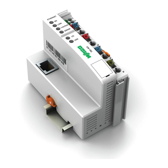
- Page 1 Modular I/O System ETHERNET StarterKit 1 510 370 74 Quick Start ETHERNET Fieldbus Controller 750-842 Version 1.0.1...
- Page 2 • General Copyright 2004 by WAGO Kontakttechnik GmbH All rights reserved. WAGO Kontakttechnik GmbH Hansastraße 27 D-32423 Minden Phone.: +49 (0) 571/8 87 – 0 Fax: +49 (0) 571/8 87 – 1 69 E-Mail: info@wago.com Web: http://www.wago.com Technical Support Phone: +49 (0) 571/8 87 –...
-
Page 3: Table Of Contents
Safety Notes ................... 6 Scope...................... 6 2 Quick Start ....................7 Node assembly ..................7 Ethernet network start-up............... 8 The first program ................. 10 Program download to the controller 750-842 ........12 Modbus/TCP DLL application examples ..........13 WAGO-I/O-SYSTEM 750 ETHERNET StarterKit 1... -
Page 4: Important Comments
WAGO Kontakttechnik GmbH declines all liability resulting from improper action and damage to WAGO products and third party products due to non-observance of the information contained in this manual. -
Page 5: Symbols
Routines or advice for efficient use of the device and software optimization. More information References on additional literature, manuals, data sheets and INTERNET pages Number Notation Number Code Example Note Decimal normal notation Hexadecimal 0x64 C notation Binary '100' Within ', '0110.0100' Nibble separated with dots WAGO-I/O-SYSTEM 750 ETHERNET StarterKit 1... -
Page 6: Safety Notes
1.5 Scope These quick start instructions describe the ETHERNET StarterKit 1 with the Ethernet fieldbus controller 750-842 and the basic components 750- 430, -530, -600, 787-602 and 759-312 of the WAGO-I/O-SYSTEM. You will find detailed information about operation, assembly and start-up in the manuals “Ethernet TCP/IP 750-342, 750-842“... -
Page 7: Quick Start
Quick Start • 7 Node assembly Further information You can also find the manuals “Ethernet TCP/IP 750-342, 750-842“ and „WAGO-I/O-PRO 32“ on our “ELECTRONICC Tools & Docs“ (Item no.: 0888-0412/0001-0101) and on the Internet under: www.wago.com 2 Quick Start 2.1 Node assembly Build up the fieldbus node as follows (from left to right): 750-842;... -
Page 8: Ethernet Network Start-Up
Connections. Your network administrator can give you more information Write down the MAC ID of the controller 750-842 which you can find on the barcode sticker or on the circuit diagram on the back of the controller. Install the ”WAGO BootP Server“ which you can find on the “ELECTRONICC Tools and Docs“... - Page 9 Please find more information about avoiding the Proxy server in the browser help section under ”Proxy server“ and ”LAN settings“. The integrated Web server will now create two Web pages (no data can be entered). Fig. 2: Webserver 750-842 ”WAGO-Ethernet TCP/IP PFC”, Status information WAGO-I/O-SYSTEM 750 ETHERNET StarterKit 1...
-
Page 10: The First Program
Fig. 3: WAGO-I/O-PRO 32, Creating a new POU A new POU “PLC_PRG“ is created using the programming language “ST“ (Fig. 3) . Before programming the controller 750-842, it must be selected. This is done via ! Extras ! PLC selection. Fig. 4: WAGO-I/O-PRO 32, Coupler selection Choose ”750-842 Vx.x Ethernet Controller“... - Page 11 Quick Start • 11 The first program The example shows the controller 750-842 with one digital input module and one digital output module. The local process image will then look like the following (byte declaration): Input_Byte %IB0: BYTE; Output_Byte %QB0: BYTE;...
-
Page 12: Program Download To The Controller 750-842
You can now download the program via ! Online ! Login. Start the program via ! Online ! Run. Note With the demo version of WAGO-I/O-PRO it is not possible to store programs permanently; i.e. the program must be downloaded and started anew after a power failure. -
Page 13: Modbus/Tcp Dll Application Examples
Restart your computer. You can find a DLL function description in the API Modbus/TCP DLL manual, chapter 2.1 ff which is on the “WAGO DLL Modbus/TCP“ CD-ROM (759-312). In the “Samples” directory you will find examples for DLL applications under Visual Basic and Visual C. - Page 14 WAGO Kontakttechnik GmbH Postfach 2880 • D-32385 Minden Hansastraße 27 • D-32423 Minden Phone: 05 71/8 87 – 0 Fax: 05 71/8 87 – 1 69 E-Mail: info@wago.com Internet: http://www.wago.com...
Need help?
Do you have a question about the 750-842 and is the answer not in the manual?
Questions and answers