
Related Manuals for R&S AFQ100A


Summary of Contents for R&S AFQ100A
- Page 1 Operating Manual I/Q Modulation Generator R&S AFQ100A 1401.3003K02 Test and Measurement 1401.3084.02 -05...
- Page 2 ® This manual describes the R&S AFQ100A, stock no. 1401.3003K02 and its options. The content corresponds to firmware version FW 3.50.201.17 and later of the R&S ® AFQ100A. ©2017 Rohde & Schwarz GmbH & Co. KG Mühldorfstr. 15, 81671 München, Germany...
- Page 3 Basic Safety Instructions Always read through and comply with the following safety instructions! All plants and locations of the Rohde & Schwarz group of companies make every effort to keep the safety standards of our products up to date and to offer our customers the highest possible degree of safety. Our products and the auxiliary equipment they require are designed, built and tested in accordance with the safety standards that apply in each case.
- Page 4 Basic Safety Instructions Symbol Meaning Symbol Meaning Caution ! Hot surface Alternating current (AC) Protective conductor terminal Direct/alternating current (DC/AC) To identify any terminal which is intended for connection to an external conductor for protection against electric shock in case of a fault, or the terminal of a protective earth Earth (Ground) Class II Equipment...
- Page 5 Basic Safety Instructions Operating states and operating positions The product may be operated only under the operating conditions and in the positions specified by the manufacturer, without the product's ventilation being obstructed. If the manufacturer's specifications are not observed, this can result in electric shock, fire and/or serious personal injury or death. Applicable local or national safety regulations and rules for the prevention of accidents must be observed in all work performed.
- Page 6 Basic Safety Instructions 6. The product may be operated only from TN/TT supply networks fuse-protected with max. 16 A (higher fuse only after consulting with the Rohde & Schwarz group of companies). 7. Do not insert the plug into sockets that are dusty or dirty. Insert the plug firmly and all the way into the socket provided for this purpose.
- Page 7 Basic Safety Instructions 2. Before you move or transport the product, read and observe the section titled "Transport". 3. As with all industrially manufactured goods, the use of substances that induce an allergic reaction (allergens) such as nickel cannot be generally excluded. If you develop an allergic reaction (such as a skin rash, frequent sneezing, red eyes or respiratory difficulties) when using a Rohde &...
- Page 8 Basic Safety Instructions 2. Adjustments, replacement of parts, maintenance and repair may be performed only by electrical experts authorized by Rohde & Schwarz. Only original parts may be used for replacing parts relevant to safety (e.g. power switches, power transformers, fuses). A safety test must always be performed after parts relevant to safety have been replaced (visual inspection, protective conductor test, insulation resistance measurement, leakage current measurement, functional test).
- Page 9 Instrucciones de seguridad elementales 3. If you use the product in a vehicle, it is the sole responsibility of the driver to drive the vehicle safely and properly. The manufacturer assumes no responsibility for accidents or collisions. Never use the product in a moving vehicle if doing so could distract the driver of the vehicle.
- Page 10 Instrucciones de seguridad elementales Además queda en la responsabilidad del usuario utilizar el producto en la forma debida. Este producto está destinado exclusivamente al uso en la industria y el laboratorio o, si ha sido expresamente autorizado, para aplicaciones de campo y de ninguna manera deberá ser utilizado de modo que alguna persona/cosa pueda sufrir daño.
- Page 11 Instrucciones de seguridad elementales Símbolo Significado Símbolo Significado Conexión a tierra El aparato está protegido en su totalidad por un aislamiento doble (reforzado) Conexión a masa Distintivo de la UE para baterías y acumuladores Más información en la sección "Eliminación/protección del medio ambiente", punto 1.
- Page 12 Instrucciones de seguridad elementales Estados operativos y posiciones de funcionamiento El producto solamente debe ser utilizado según lo indicado por el fabricante respecto a los estados operativos y posiciones de funcionamiento sin que se obstruya la ventilación. Si no se siguen las indicaciones del fabricante, pueden producirse choques eléctricos, incendios y/o lesiones graves con posible consecuencia de muerte.
- Page 13 Instrucciones de seguridad elementales integran productos sin interruptor en bastidores o instalaciones, se deberá colocar el interruptor en el nivel de la instalación. 5. No utilice nunca el producto si está dañado el cable de conexión a red. Compruebe regularmente el correcto estado de los cables de conexión a red.
- Page 14 Instrucciones de seguridad elementales 17. No utilice el producto en condiciones en las que pueda producirse o ya se hayan producido condensaciones sobre el producto o en el interior de éste, como p. ej. al desplazarlo de un lugar frío a otro caliente.
- Page 15 Instrucciones de seguridad elementales pueden causar perturbaciones radioeléctricas en entornos residenciales debido a posibles perturbaciones guiadas o radiadas. En este caso, se le podrá solicitar al operador que tome las medidas adecuadas para eliminar estas perturbaciones. Aparato de clase B: Aparato adecuado para su uso en entornos residenciales, así...
- Page 16 Instrucciones de seguridad elementales 8. En caso de devolver baterías de litio a las filiales de Rohde & Schwarz, debe cumplirse las normativas sobre los modos de transporte (IATA-DGR, código IMDG, ADR, RID). Transporte 1. El producto puede tener un peso elevado. Por eso es necesario desplazarlo o transportarlo con precaución y, si es necesario, usando un sistema de elevación adecuado (p.
-
Page 17: Customer Support
Customer Support Technical support – where and when you need it For quick, expert help with any Rohde & Schwarz equipment, contact one of our Customer Support Centers. A team of highly qualified engineers provides telephone support and will work with you to find a solution to your query on any aspect of the operation, programming or applications of Rohde &... -
Page 18: Table Of Contents
R&S AFQ100A Contents Contents Chappter overview of the Operating Manual for the I/Q Modulation Generator R&S AFQ100A. Documentation Overview Putting into Operation Getting Started Manual Operation Instrument Functions Remote Control Basics Remote Control Commands Maintenance and Remote Control Interfaces Error Messages... -
Page 19: Documentation Overview
The release notes list new features, improvements and known issues of the current firmware version, and describe the firmware installation. The open source acknowledgment document provides verbatim license texts of the used open source software, see www.rohde-schwarz.com/firmware/afq100a. Application notes, application cards, white papers, etc. - Page 20 R&S AFQ100A Contents - Putting into Operation Contents - Chapter 1 "Putting into Operation" Putting into Operation ............. 1.1 Introduction - Putting into Operation..............1.1 Legend for Front Panel View................1.1 Legend for Rear Panel View ................1.7 Putting into Operation..................1.12 Unpacking the Instrument ..............
-
Page 21: Putting Into Operation
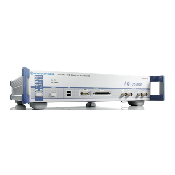
R&S AFQ100A Putting into Operation Putting into Operation Introduction - Putting into Operation Chapter 1, "Putting into Operation" explains the control elements and connectors of the R&S AFQ I/Q Modulation Generator with the aid of the front and rear views and describes how to put the instrument into operation. - Page 22 R&S AFQ100A Putting into Operation Fig. 1-1 Front panel view Status LEDs for instrument state See chapter 6, ERROR section "System Indicates that an error occurred during operation. Subsystem" Only errors are indicated that impair further instrument operation, e.g. a hardware fault. The error must be eliminated before correct instrument operation can be ensured.
- Page 23 R&S AFQ100A Putting into Operation Switch See section On/Off Switch "Switching On" on The On/Off switch switches the instrument from the page 1.17 standby mode to the operating state provided the power switch at the instrument rear is switched on.
- Page 24 R&S AFQ100A Putting into Operation Trigger key along with two status LEDs See data sheet TRIGGER The trigger key covers various features, which are selected by pressing the Trigger button in a different manner. Pressing short A manual trigger event or a manual segment trigger...
-
Page 25: Digital Outputs
R&S AFQ100A Putting into Operation Digital outputs The instrument has two digital outputs, Port 1 and 2, See chapter 8, featuring LVDS transmission: "Maintenance and Port 1 Remote Control This socket provides a multiplexed output to connect Interfaces" other R&S instruments, e.g. the R&S SMU Vector Signal Generator. -
Page 26: Analog Outputs
R&S AFQ100A Putting into Operation Analog outputs See data sheet Analog I/Q output (inverting and non inverting): The loaded waveforms are output at a nominal level of 0.5 Volts at two BNC connectors I and Q. The impedance amounts to 50 Ohm. Four BNC connectors I and I BAR, Q and Q BAR are available for differential output. -
Page 27: Legend For Rear Panel View
R&S AFQ100A Legend for Rear Panel View Legend for Rear Panel View This section gives an overview of connectors on the rear panel of the R&S AFQ, they are explained clockwise, starting on the top of the left hand side. Each connector is briefly described and a reference is given to the chapters containing detailed information. - Page 28 R&S AFQ100A Legend for Rear Panel View IEC/IEEE-bus connector IEC 625/IEEE 488 See data sheet and IEC-bus (IEEE 488) interface for remote control of the chapter 5, section R&S AFQ. "IEC/IEE Bus Interface" AC supply See data sheet and Power switch section "Connecting...
- Page 29 R&S AFQ100A Legend for Rear Panel View BERT See data sheet and Four BERT inputs chapter 4, section The BERT connectors either receive clock and data "Trigger Dialog" signals for measuring a bit error rate they receive control signals for segment hopping (FHOP) while generating multi segment waveforms.
- Page 30 R&S AFQ100A Legend for Rear Panel View Monitor MONITOR ANALOG See data sheet and The 15-pin Sub-D female connector is intended for section "Connecting connecting an external VGA monitor with an analog an External Monitor" input. on page 1.24 USB connectors type A...
- Page 31 R&S AFQ100A Legend for Rear Panel View Next See data sheet and NEXT "Trigger Dialog" This trigger input indicates the next (i.e. the 2nd, 3rd, 4th, ...) segment of a multi segment waveform, which can be a compound of e.g. a sine, a rectangular, and a sawtooth signal.
-
Page 32: Putting Into Operation
R&S AFQ100A Putting into Operation Putting into Operation The following section describes the procedure for putting the instrument into operation and the connection of peripherals such as keyboard, mouse, and monitor. It contains general safety instructions for instrument operation. The installation of options and the firmware update are described in chapter 4 of the service manual. -
Page 33: Safety Instructions
R&S AFQ100A Putting into Operation Safety Instructions General Precautions NOTICE Instrument damage caused by disregarding the following precautions! Any non-compliance with the following precautions may cause damage to the instrument. Prior to putting the instrument into operation, check the following: The covers of the housing are in place and screwed on. - Page 34 R&S AFQ100A Putting into Operation Setting up the Instrument CAUTION Safe operation with support feet! Stacked instruments may slip off. Secure stacked instruments against slipping (e.g. by locking the feet to the top of the front-panel frame). The feet must be fully folded in or folded out. Only then a stable position of the instrument and reliable operation can be ensured.
- Page 35 R&S AFQ100A Putting into Operation Removing and Installing the Hard Disk For security reasons the R&S AFQ is equipped with a removable hard disk. The hard disk is located at the front of the instrument. NOTICE Risk of instrument damage and data loss! During operation the instrument is accessing the hard disk.
-
Page 36: Connecting The R&S Afq To The Ac Supply
R&S AFQ100A Putting into Operation Connecting the R&S AFQ to the AC Supply The R&S AFQ is automatically matched to the applied AC voltage (see rear panel). There is no need to set the voltage manually or change fuses. The AC supply connector is at the rear of the unit (see below). -
Page 37: Switching On
R&S AFQ100A Putting into Operation Switching On Power connector Connect the modulation generator to the AC supply by means of the supplied power cable. Press the main Power switch at the rear of the instrument to position I. After power-up the instrument is either ready for operation... -
Page 38: Booting The R&S Afq
R&S AFQ100A Putting into Operation Booting the R&S AFQ After instrument switch-on, the R&S signal generator automatically performs a system check, boots the Windows XP operating system and subsequently boots the instrument firmware. If an external monitor is connected to the instrument, the installed BIOS version and the processor characteristics are indicated for a few seconds in the start display after instrument switch-on. -
Page 39: Switching Off
R&S AFQ100A Putting into Operation Switching Off Press the ON/STANDBY switch on the front panel. The R&S AFQ stores the current setting on the hard disk before it shuts down the windows operating system. Then the AC supply is switched to standby mode. -
Page 40: Function Check
R&S AFQ100A Function Check Function Check The instrument automatically monitors the main functions when the instrument is switched on and continuously during operation. If a fault is detected, the front panel LED ERROR indicates the error state. The error can be queried with commands SYSTem:ERRor:ALL?, SYSTem:ERRor[:NEXT], and SYSTem:SERRor. -
Page 41: Default Settings
R&S AFQ100A Default Settings Default Settings The instrument is set to a defined state with common command *RST or the key combination on an external keyboard. The following table gives an overview of the presets for the most important generator settings. The other presets can be found in the preset tables of the individual menus and the information accompanying the IEC/IEEE-bus commands. - Page 42 R&S AFQ100A Windows XP The I/Q modulation generator is equipped with the Windows XP operating system. The configuration of the operating system is optimally adapted to modulation generator functions in the factory. Changes in the system setup are only required when peripherals like a keyboard is installed or in the event that the network configuration does not comply with the default settings (see section "Connecting the R&S AFQ...
-
Page 43: Connecting An External Keyboard
R&S AFQ100A Connecting an External Keyboard Connecting an External Keyboard A commercial, external keyboard with USB interface can be connected to the R&S AFQ. A keyboard is a prerequisite for manual control of the instrument and for operation of Windows XP without a Remote Desktop connection to an external PC. -
Page 44: Connecting A Mouse
R&S AFQ100A Connecting a Mouse Connecting a Mouse A commercial mouse with a USB interface can be connected to the R&S AFQ. A mouse simplifies control of the block diagram and of associated menus in manual control. It is sufficient for operation of Windows XP when used together with the on-screen keyboard. -
Page 45: Connecting The R&S Afq To A Network (Lan)
R&S AFQ100A Connecting the R&S AFQ to a Network (LAN) Connecting the R&S AFQ to a Network (LAN) The R&S AFQ is equipped with a network interface and can be connected to an Ethernet LAN (local area network). Provided the appropriate rights have been assigned by the network administrator and the Window XP firewall configuration is adapted accordingly, files can be transmitted via the network, and network resources, e.g. - Page 46 R&S AFQ100A Connecting the R&S AFQ to a Network (LAN) Configuring the R&S AFQ for Network Operation The network interface functions with 10/100/1000Mbps Ethernet IEEE 802.3u. The TCP/IP network protocol and the associated network services are preconfigured. For data exchange in a LAN, each connected PC or instrument must be accessible via an IP address or via an unambiguous computer name.
- Page 47 R&S AFQ100A Connecting the R&S AFQ to a Network (LAN) The configuration of the R&S AFQ for networking is performed in the Windows XP menus. The operating system can only be accessed if an external keyboard and/or mouse and a external monitor are connected.
- Page 48 R&S AFQ100A Connecting the R&S AFQ to a Network (LAN) Click on Network Connections at the bottom right of the Network and Internet Connections menu. Click on Local Area Connection in the Network Connections menu (at the right) 1401.3078.62 1.28...
- Page 49 R&S AFQ100A Connecting the R&S AFQ to a Network (LAN) On the General tab, select Internet Protocol (TCP/IP) in the field This connection uses the following items: and then click on the Properties button. In the Internet Protocol (TCP/IP) Properties menu, enter the IP address in the Use the following IP address: field (the complete data can be queried from the network administrator).
- Page 50 R&S AFQ100A Connecting the R&S AFQ to a Network (LAN) Query Computer Name Open the start menu, select My Computer and open the context menu by pressing the right mouse key. Click on Properties and select the Computer Name tab in the menu.
- Page 51 R&S AFQ100A Connecting the R&S AFQ to a Network (LAN) Configuring Internet Connection Firewall The Windows XP Firewall blocks all network communication which is not initialized by the controller itself or which is defined as unwanted. It protects the controller from an attack of hostile users and programs.
- Page 52 R&S AFQ100A Connecting the R&S AFQ to a Network (LAN) Select tab Exceptions and activate check box File and Printer Sharing. Confirm entry with Ok, 1401.3078.62 1.32...
- Page 53 R&S AFQ100A Connecting the R&S AFQ to a Network (LAN) Accessing Directories in the Network Access to network drives depends on access rights and whether the drives in question have been enabled. The complete integration of the R&S AFQ into a larger network with the necessary allocation of rights is highly complex and normally performed by a network administrator.
-
Page 54: Manual Remote Control Via An External Controller
R&S AFQ100A Manual Remote Control via an External Controller Manual Remote Control via an External Controller The R&S AFQ can be manually remote-controlled from an external PC via a network link. This allows convenient operation of the vector modulation generator from the desktop although the instrument is integrated in a rack in the next room. -
Page 55: Configuration For Manual Remote Control Via Windows Remote Desktop Connection
R&S AFQ100A Manual Remote Control via an External Controller Configuration for Manual Remote Control via Windows Remote Desktop Connection The instrument is operated with the aid of the Windows program Remote Desktop Connection which is provided free-of-charge by Microsoft in the download area of the Internet (http://www.microsoft.com). - Page 56 R&S AFQ100A Manual Remote Control via an External Controller Enable Remote Desktop Connection on R&S AFQ The configuration is performed in the Windows XP menus. The operating system can only be accessed if an external keyboard and monitor is connected. A mouse is recommended for convenient operation of Windows XP.
- Page 57 R&S AFQ100A Manual Remote Control via an External Controller Install Remote Desktop and Establish Connection on the Windows PC The Remote Desktop Connection program of Microsoft is available on the Internet for the Windows 95 operating system and its successors as a free-of-charge download. Following the instructions on the Internet, it can be loaded onto any external PC.
- Page 58 R&S AFQ100A Manual Remote Control via an External Controller Login data can be stored with the Save As button. If the login data is stored as a default.rdp file, the connection to the R&S AFQ is offered as the default when the program is started. If the data is stored under another name, the R&S AFQ link is available in the selection list opened with the button of the Computer: entry field.
- Page 59 R&S AFQ100A Manual Remote Control via an External Controller Cut Manual Remote Control Connection via Remote Desktop The connection can be cut either on the R&S AFQ or on the external PC. Cutting the connection does not disable it. It can be established again any time.
-
Page 60: Configuration For Manual Remote Control Via Ultr@Vnc
R&S AFQ100A Manual Remote Control via an External Controller Configuration for Manual Remote Control via Ultr@VNC The instrument is operated with the aid of the program Ultr@VNC. The program is included in operating system Linux/Unix. It is available as a free-of-charge download on the internet for operating system Window XP (http://ultravnc.sourceforge.net/download.htm) - Page 61 R&S AFQ100A Manual Remote Control via an External Controller Install and Enable VNC Connection on R&S AFQ The Ultr@VNC program is available on the Internet as a free-of-charge download. Following the instructions on the Internet, it can be copied onto the R&S AFQ.
- Page 62 R&S AFQ100A Manual Remote Control via an External Controller b) Select all entries in the Additional Task Panel c) A successful installation is indicated by a message d) At the same time a warning is displayed stating that a password must be set.
- Page 63 R&S AFQ100A Manual Remote Control via an External Controller e) After clicking on OK in the warning panel the Default Local System Properties panel opens. A password with a length of at least five digits must be entered. This password is used on the remote PC to access the R&S AFQ.
- Page 64 R&S AFQ100A Manual Remote Control via an External Controller Configuring Internet Connection Firewall for VNC Connection To enable manual remote control by other controllers in a local network via VNC connection, the connection must be specifically permitted in the firewall.
- Page 65 R&S AFQ100A Manual Remote Control via an External Controller Select Run Ultr@VNC SERVER and click on Ok. Activate check box Run Ultr@VNC SERVER in the Exception tab and click on Ok. 1401.3078.62 1.45...
- Page 66 R&S AFQ100A Manual Remote Control via an External Controller Establish Manual Remote Control on the Linux/Unix PC The VNC program is available per default for Linux/Unix operating systems. Only three steps are necessary to establish the connection to the R&S AFQ: Start the internet browser on the PC.
- Page 67 R&S AFQ100A Manual Remote Control via an External Controller Install VNC Viewer and Establish VNC Connection on the Windows PC The Ultr@VNC program is available on the Internet as a free-of-charge download. Following the instructions on the Internet, the program can be copied onto the external Windows PC.
- Page 68 R&S AFQ100A Manual Remote Control via an External Controller Cut Manual Remote Control Connection via Ultr@VNC The connection can be cut either on the R&S AFQ or on the external PC. Cutting the connection does not disable it. It can be established again any time.
-
Page 69: Using Norton Antivirus
R&S AFQ100A Using Norton Antivirus Using Norton Antivirus Virus-protection software Symantec Norton Antivirus 2005 has been successfully tested for compatibility with the measurement instrument software on R&S AFQ. However, Norton Antivirus may affect the behavior of the instrument in terms of settling time or stability. - Page 70 R&S AFQ100A Using Norton Antivirus Click on the Change button 1401.3078.62 1.50...
- Page 71 R&S AFQ100A Using Norton Antivirus Activate a) Drive D: [DATA] b) System managed size Click on the Set button Click on the Close button, the dialog closes. Now the program Norton Antivirus can be installed. 1401.3078.62 1.51...
- Page 72 R&S AFQ100A Contents - Getting Started Contents - Chapter 2 "Getting Started" Getting Started ................. 2.1 Outline of the Instrument .................. 2.1 Schematic Description................. 2.1 Use of the Instrument ................2.1 Main Applications ..................... 2.2 Feature Summary..................... 2.3 Block Diagram ....................2.4 Two ways to operate the instrument ..............
-
Page 73: Getting Started
R&S AFQ100A Outline of the Instrument Getting Started Outline of the Instrument Schematic Description The R&S AFQ I/Q modulation generator forms analog signals to be modulated onto RF carriers by other instruments. The instrument converts digital baseband signals to analog signals which can be further processed by an RF generator. -
Page 74: Main Applications
R&S AFQ100A Main Applications Main Applications R&S AFQ is mainly used for generating modulation signals for an RF generator to check the data taken by a receiver. Moreover, RF generators with I/Q inputs can also be tested. Gain and phase of the two channels I and Q can be adjusted, hence accounting for non ideal characteristics of the RF generator to be driven. -
Page 75: Feature Summary
R&S AFQ100A Feature Summary Feature Summary The instrument's main features are: The system clock frequency f amounts to 300 MHz, thus processing a large amount of digital system data per second. The maximum resolution of the I and the Q signals is 16 bits each. -
Page 76: Block Diagram
R&S AFQ100A Block Diagram Block Diagram Figure 2-1: The instrument features a correction filter accounting for the frequency response of the two I/Q input amplifiers and the RF modulator of the user's RF generator. 1401.3078.62... -
Page 77: Two Ways To Operate The Instrument
R&S AFQ100A Two ways to operate the instrument Two ways to operate the instrument There are two possibilities to operate the instrument: Using the instrument's own graphical user interface (GUI) a) stand alone, plugging in an external monitor, keyboard, and mouse directly b) using Windows XP Pro's Remote Desktop feature or the program VNC via LAN, as described in the first chapter. - Page 78 R&S AFQ100A Contents - Manual Operation Contents - Chapter 3 "Manual Operation" Manual Operation ..............3.1 Introduction - Manual Operation............... 3.1 Legend of Manual Controls ................3.1 On-Screen Keyboard................3.2 Operating Concept ................... 3.3 Automatically Launching a Program or a Command File....3.6 Display......................
-
Page 79: Manual Operation
R&S AFQ100A Introduction - Manual Operation Manual Operation Introduction - Manual Operation The present chapter describes the manual control of the R&S AFQ, even though the modulation generator is primarily intended to be remote-controlled via the GPIB interface or a LAN connection. -
Page 80: On-Screen Keyboard
R&S AFQ100A Legend of Manual Controls Key of PC keyboard / Function Short description of Function Button function Closes dialogs Closes an active dialog. Ctrl + G Hide Minimizes the active dialog. Pressing the respective button in Ctrl + H the Winbar opens the dialog again. -
Page 81: Operating Concept
R&S AFQ100A Operating Concept Operating Concept The operating concept for manual control enables the user to make settings as intuitively as possible and at the same time gives a permanent overview of characteristics of the generated signal and of the current instrument state. - Page 82 R&S AFQ100A Operating Concept To offer the user a familiar environment, operation is very similar to the operation of Windows user interfaces. All dialogs and tables are made up of known elements, e.g. selection lists check boxes or entry fields A blue frame indicates that the selected item is active.
- Page 83 R&S AFQ100A Operating Concept Help functions support the user Numerous help functions support the user in signal configuration. The valid setting range can be displayed for each numeric parameter. This requires a short wait after activation of the entry field. The range is then displayed automatically after a few seconds in a yellow flyout window.
-
Page 84: Automatically Launching A Program Or A Command File
R&S AFQ100A Operating Concept Automatically Launching a Program or a Command File RSAutoLaunch is a program which handles messages of the operating system which are sent when the user plugs in or removes devices such as drives or USB memory sticks. The program will start executable files which are automatically detected. -
Page 85: Display
R&S AFQ100A Display Display The external display shows the current modulation generator state and offers graphical elements for direct operation. It is divided into three sections: The header along with an info line reports the current state with status, error and warning messages. -
Page 86: Status Information And Messages - Display
R&S AFQ100A Display Status Information and Messages - Display The status information and messages are displayed in the header section of the screen. The messages differ with respect to their importance (errors, warnings, info) and the time of their appearance (brief and permanent messages). -
Page 87: Info Window - Display
R&S AFQ100A Display Info Window - Display A few operating states and the current message are displayed in the info line (see also chapter 9 "Error Messages"). The info window with a list of current permanent messages and a detailed description of each message can be opened by clicking on the Info softkey. - Page 88 R&S AFQ100A Display With the aid of the softkey buttons, error messages can be cleared and a history of all messages called. Delete Clears the highlighted message. This button is available only if the history of the messages is displayed.
-
Page 89: Block Diagram - Display
R&S AFQ100A Display Block Diagram - Display The block diagram in the main window shows provided options, signal configuration and the currently selected signal flow of the modulator with inputs and outputs used. Signal generation can be completely operated from the block diagram. The highlighted function block can be directly switched on and off with key combination. - Page 90 R&S AFQ100A Display The input/output symbols in the block diagram show the currently used inputs and outputs of the modulation generator. Unused inputs and outputs are not shown. The lines indicate the signal flow. Symbols and labels refer to the corresponding inputs and outputs on the front and rear panel of the modulation generator.
-
Page 91: Winbar And Softkeys - Display
R&S AFQ100A Display Winbar and Softkeys - Display The Winbar with eight buttons is displayed below the block diagram. Labelled buttons represent open dialogs, the label indicates the dialog. If several dialogs are open, the button of the currently active dialog is displayed in a lighter colour. - Page 92 R&S AFQ100A Display This section describes the dialog structure. Dialog operation is described in section "Dialog Operation" on page 3.20, the setting of parameters in section "Setting Parameters" on page 3.16. The dialogs are in Windows format. They differ in details depending on their function but they consist of the same main elements.
- Page 93 R&S AFQ100A Display Check-box field If the check box is ticked, the associated parameter setting is active (e.g. switched on). Dialog area Several fields of associated but separately set parameters can be organized in a dialog area. The dialog area is framed and labelled with the function common to all parameters (e.g.
-
Page 94: Setting Parameters
R&S AFQ100A Setting Parameters Setting Parameters The instrument offers several and sometimes alternative possibilities for setting parameters. Manual operation is possible with the aid of a mouse and/or from an external keyboard. Operation of the instrument with the aid of these control media is shown in the tables below. -
Page 95: Selecting A Control Element - Setting Parameters
R&S AFQ100A Setting Parameters Selecting a Control Element - Setting Parameters Control elements are always selected in the same way no matter whether a function block in the diagram, a menu in the menu tree, a parameter in the dialog or an entry in a list or table is concerned. -
Page 96: Selecting And Exiting A Dialog Area - Setting Parameters
R&S AFQ100A Setting Parameters Selecting and Exiting a Dialog Area - Setting Parameters Some dialogs are organized in areas. The cursor can be moved either only within an area or between the higher-level dialog areas. This applies to the file select dialogs when files are saved or loaded. e.g. -
Page 97: Terminating Entries - Setting Parameters
R&S AFQ100A Setting Parameters Terminating Entries - Setting Parameters Variations by means of the cursor keys are immediately set, e.g. delay settings. All other parameter settings have to be confirmed by a pressing the key or one of the unit key Enter combinations. -
Page 98: Dialog Operation
R&S AFQ100A Dialog Operation Dialog Operation Dialogs are operated with the aid of the Winbar buttons and with key combinations. key combination minimizes an active dialog. It is displayed in the form of a Winbar Ctrl button. key combinations maximize the corresponding dialog. -
Page 99: Editors
R&S AFQ100A Editors Editors The GUI provides user-friendly editors for defining data lists. The lists are saved to files and may thus have any length. The file name of the lists and the directory to which the files are saved are user-selectable. The file prefix is different for each list type and is permanently assigned by the system (see section "File... - Page 100 R&S AFQ100A Editors Function PC keyboard Mouse Call up editor. Mark the Edit Data... button in the individual Click on the Edit Data... button in the The cursor marks the first row individual dialog. dialog and press the Enter key.
-
Page 101: Online Help
R&S AFQ100A Online Help Online Help The instrument is equipped with a context-sensitive help function. A help page is available for each parameter and can be called any time during instrument operation. The context-sensitive page which is opened with the key is part of a comprehensive help system. - Page 102 R&S AFQ100A Online Help Operation of context-sensitive help Function PC keyboard Mouse Open the help system. Press F1 key. The help page for the respective parameter is displayed. Close the help system: Press F1 key again. Activate the link: Select link using the cursor keys and Click on the link.
-
Page 103: File Management
R&S AFQ100A File Management File Management The instrument uses files to save all instrument data, i.e. system and user data. The user data includes saved instrument settings, data for the different digital standards, lists for the List mode and the user correction as well as the waveforms for multcarrier CW generation and the arbitrary waveform generator. -
Page 104: Select / Save Instrument Settings - File Management
R&S AFQ100A File Management Select / Save Instrument Settings - File Management The File menu offers access to functions for loading or saving instrument settings. Clears the current instrument settings. All devices are reset and conform to the default settings as it is called by the *RST command. - Page 105 R&S AFQ100A File Management Save Saves the current instrument settings. If the instrument works with loaded settings the current changes will overwrite the setttings in the file. File name and path cannot be entered. If the instrument does not work with loaded settings the function Save as ... will be called automatically.
-
Page 106: Select / Save Lists - File Management
R&S AFQ100A File Management Select / Save Lists - File Management File select windows as Load Waveform, Select List or New List offer access to functions for loading and saving user data. Lists, Complex modulation and control data or Waveforms are handled within these windows. - Page 107 R&S AFQ100A File Management Select Loads user data. Select the drive and the directory in the left window. The available files are listed in the right window. Press the key or click on the Select button to load the file data.
-
Page 108: File Manager
R&S AFQ100A File Management File Manager The File Manager allows general file management such as copying, shifting, renaming and deleting files as well as generating new directories. Thus, also externally created files, for example waveforms created by using the R&S WinIQSIM2 program, can be saved to the instrument by copying them from a memory stick or a network to the internal hard disk. - Page 109 R&S AFQ100A File Management Delete file: Mark file and then press the Delete button. Prior to deletion, a confirmation query is displayed which the user must confirm for this file to be deleted. Create new directory: Mark drive or directory level where the new directory is to be created and then press the Create New Directory button.
- Page 110 R&S AFQ100A File Management Contents - Chapter 4 "Instrument Functions" Instrument Functions............... 4.1 Overview of Instrument Functions..............4.1 Menu and Status Line ................. 4.1 Arbitrary Waveform Generator (ARB) .............. 4.2 Introduction..................4.2 Baseband Block....................4.3 ARB Dialog ..................4.3 ARB - Sine Test Signals Dialog ............4.5 ARB - Rectangular Test Signals Dialog ..........
- Page 111 R&S AFQ100A Contents - Instrument Functions General Instrument Settings................4.82 Default Instrument Settings ............... 4.82 Setup Menu ..................4.83 Internal Adjustments- Setup System ..........4.83 Hardware Config - Setup System............4.85 Gui Update - Setup System............... 4.86 Software / Options - Setup System ........... 4.86 Install SW-Options - Setup System ...........
-
Page 112: Instrument Functions
R&S AFQ100A Overview of Instrument Functions Instrument Functions Overview of Instrument Functions This chapter explains the functions of the I/Q modulator and the options available in the setting dialogs. The associated IEC/IEEE bus command is specified for each parameter where applicable. -
Page 113: Arbitrary Waveform Generator (Arb)
R&S AFQ100A Arbitrary Waveform Generator (ARB) Arbitrary Waveform Generator (ARB) Introduction The Arbitrary Waveform Generator is an I/Q modulation source forming an integral part of the instrument. It can be used to output any externally calculated modulation signals or internally generated test signals. -
Page 114: Baseband Block
R&S AFQ100A Baseband Block Baseband Block The settings for activation and configuration of the external or internal waveform signal can be accessed in the block diagram via the Baseband function block or by selecting Baseband in the Edit menu. ARB Dialog The dialog for setting the Arbitrary Waveform Generator (ARB) can be opened in the Baseband block of the main window, clicking the config... - Page 115 R&S AFQ100A Baseband Block Calls the dialog for loading a waveform file.. Load Waveform The files last used are listed in the Recent Data Sets section on top of the dialog. The directory can be selected down to the left.
-
Page 116: Arb - Sine Test Signals Dialog
R&S AFQ100A Baseband Block Opens the dialog for creating the sine test signals "ARB - Sine Test Sine Testsignals... Signals" on page 4.5. Opens the dialog for creating the test signals "ARB - Rectangular Test Rect Testsignals... Signals" on page 4.7. - Page 117 R&S AFQ100A Baseband Block Enters the sample clock frequency for generating a sine test signal. Sample Clock 1 kHz ... 300 MHz The sample clock rate must not exceed the maximum ARB clock rate of 300 MHz. Sample clock rates between 300 MHz and 600 MHz are not available and set to maximum ARB clock rate of 300 MHz.
-
Page 118: Arb - Rectangular Test Signals Dialog
R&S AFQ100A Baseband Block ARB - Rectangular Test Signals Dialog The Rectangular Test Signals dialog is accessed via the ARB dialog. The dialog can be used to configure a rectangular test signal. A rectangular test signal with a duty factor of 0.5 is created. -
Page 119: Arb - Table Sine Test Signal Dialog
R&S AFQ100A Baseband Block Enters a DC component. Offset - Rect Test Remote-control command: Signal SOUR:TSIG:RECT:OFFS 0.1 Generates a signal and saves it to a file on HD. Generate Signal HD - The Create Test Signal window opens automatically and the signal Rect Test Signal can be stored as a waveform file. - Page 120 R&S AFQ100A Baseband Block Enters the sample clock frequency for generating a table sine test Sample Clock - Table signal. Sine Test Signal 1 kHz ... 300 MHz The sample clock rate must not exceed the maximum ARB clock rate of 300 MHz.
- Page 121 R&S AFQ100A Baseband Block The two sine waves can be configured in the sections Sine 1 and Sine 2. Sets the number of periods for the sine waves. The values are set Periods - Table Sine separately for each component of the test signal, as provided in Test Signal section Sine 1 and section Sine 2 of the dialog.
-
Page 122: Arb - Test Pattern Dialog
R&S AFQ100A Baseband Block ARB - Test Pattern Dialog The Test Pattern dialog is accessed via the ARB main dialog. The dialog can be used to configure a continuous signal. Each path (I and Q) gets a pattern for the signal. The pattern is entered as a decimal number, which is decimal-to-binary converted internally. -
Page 123: Trigger Dialog
R&S AFQ100A Baseband Block Trigger Dialog The Trigger dialog is accessed via the Baseband block. The Trigger dialog is used to enter trigger settings. The dialog offers selection of internal triggering as well as external triggering via the external trigger connectors TRIG and NEXT. In case a multi segment waveform is selected, the segment trigger mode can be set. - Page 124 R&S AFQ100A Baseband Block The Trigger Configuration section is where the trigger for the waveform is set. Various parameters will be provided for the settings, depending on the selected trigger source. Selects the trigger mode. Run Mode - Trigger For multi segment waveforms, the segment output is determined by Segment Mode settings, on page 4.18.
- Page 125 R&S AFQ100A Baseband Block When retrigger is enabled the current signal output is reset at a trigger during signal generation. Remote-control command: SOUR:TRIG:MODE SING Multiple output of the waveform when a trigger event Repeat N occurs. Times Note: Run mode Repeat N Times is enabled only in...
- Page 126 R&S AFQ100A Baseband Block (Trigger mode Repeat Count only) Repeat Count - Trigger Sets a repeat rate for restarting the waveform after a trigger event occurs. The waveform can be repeated up to 100 times, provided that Enable Retrigger is set (see...
- Page 127 R&S AFQ100A Baseband Block using either the command *GET, *TRG or TRIG:EXEC. Remote-control command: SOUR:TRIG:SOUR BUS (Sync mode Master and Normal only) Auto The trigger event is executed internally by the firmware. Signal output starts immediately when a signal is loaded and State is on. Trigger events are ignored.
- Page 128 R&S AFQ100A Baseband Block Sets the duration for inhibiting a new trigger event subsequent to Inhibit - Trigger triggering. A restart can only be inhibited with an external trigger source. In the Retrigger mode every trigger signal causes signal output to restart.
- Page 129 R&S AFQ100A Baseband Block The Segment Trigger Configuration section is where the trigger for the switch between the segments of a multi segment waveform is set. Various parameters will be provided for the settings, depending on the selected trigger source. This section is indicated only if a multi segment waveform is loaded.
- Page 130 R&S AFQ100A Baseband Block Run Mode "Repeat N Times" The following segment starts to be output immediately after a segment trigger event occurs. After finishing the run of the last segment, signal generation switches to idle mode. A segment trigger event is without effect. Restart of signal...
- Page 131 R&S AFQ100A Baseband Block Run Mode "Single" When a segment trigger event occurs, the following segment is output after finishing the current one. A trigger event during output of the last segment effects, that signal generation stops after completing the segment. A segment trigger event is without effect.
- Page 132 R&S AFQ100A Baseband Block Run Mode "Single" Each segment trigger event switches to the next segment. A regular trigger event resets signal generation. Run Mode "Repeat N Times" Each segment trigger event switches to the next segment. A regular trigger event resets signal generation.
- Page 133 R&S AFQ100A Baseband Block Repeat N Times Run Mode "Repeat N Times" The next segment starts to be output after a segment trigger event. After finishing the waveform the instrument switches to the idle mode. A regular trigger event restarts signal generation.
- Page 134 R&S AFQ100A Baseband Block The segment trigger event is executed by remote control using the command TRIG:SEGM:EXEC. Remote-control command: SOUR:TRIG:SEGM:SOUR BUS Auto (segment mode Single or Repeat N Times only) The segment trigger event is executed internally by the firmware. Segment trigger events are ignored.
- Page 135 R&S AFQ100A Baseband Block FHOP Parallel The index of the next segment is determined via a data signal on the parallel FHOP bus. The signal is fed in parallel as a binary digit via the BERT BNC connectors. With the next segment trigger event the signals are loaded as segment index.
- Page 136 R&S AFQ100A Baseband Block Function of data bits of FHOP bus (fhop_data line, see figure above) and their function for controlling multi segment waveform generation. Data bit name (bit number) Function Bit 39 to 10 Bits must be set to 0...
- Page 137 R&S AFQ100A Baseband Block Selects the slope of the active edge of the external trigger signal. The Slope - Segment slope can only be set for an external trigger signal that is fed in via the Trigger NEXT connector on the rear panel.
-
Page 138: Marker Dialog
R&S AFQ100A Baseband Block Marker Dialog In the Marker dialog markers can be defined in addition to marker settings that may be defined already in the waveform file. The marker dialog is accessed via the Baseband block. In section Reconfigure up to four markers signals can be set in addition to marker settings already defined in the waveform file. - Page 139 R&S AFQ100A Baseband Block A regular marker signal (strobe) is generated. The Pulse pulse frequency is defined by entering a divider. The frequency is derived by dividing the sample rate by the divider. When Pulse is selected an input box for...
- Page 140 R&S AFQ100A Baseband Block A marker signal that is defined by a pattern of List samples is generated. When List is selected an input box for entering the pattern is displayed (see also List , on page4.30). The samples can be assorted by entering either particular samples or sample ranges, each defined by the sampleindex and the signal value (0/1).
- Page 141 R&S AFQ100A Baseband Block (Marker signal output Ratio only) OnTime / Off Time - Sets the number of samples for the ON time and the OFF time, Marker respectively. A period of the marker signal lasts one on and off cycle.
-
Page 142: Clock Dialog
R&S AFQ100A Baseband Block Displays the dynamic range within which the delay of the marker Current Range signals can be set without restarting the marker and signal. Without Recalculation - Marker Remote-control command: SOUR:TRIG:OUTP2:DEL:MAX? SOUR:TRIG:OUTP2:DEL:MIN? Selecting this check box restricts the marker delay setting range to the Fix Delay to Current dynamic range. - Page 143 R&S AFQ100A Baseband Block Selects the clock source for loading the waveform file. Source - Memory Clock The internal clock reference is used to generate the Internal sample clock. Remote-control command: SOUR:CLOC:SOUR INT The external clock reference is fed in as the sample External clock via the CLOCK IN connector.
- Page 144 R&S AFQ100A Baseband Block (Clock source external only) Measured External Indicates the measured frequency of the external clock signal. Thus, a Clock - Memory Clock screening of the external clock is possible. The measured frequency is indicated only when the clock source External is selected.
- Page 145 R&S AFQ100A Baseband Block (Analog signal output only) Sync Mode - Selects the mode for synchronization with other R&S AFQ Reference Clock I/Q Modulation Generators. This clock is used for synchronizing several connected R&S AFQ I/Q Modulation Generators (see also the following section Setting Up Several Connected R&S AFQs for...
- Page 146 R&S AFQ100A Baseband Block Selects the reference clock source. Source - Reference Clock Note: The Internal Reference Clock Source is available only in the reference clock synchronization modes Normal and Master. If the instrument is set to Slave or Last slave mode the reference clock source is set to External.
-
Page 147: Setting Up Several Connected R&S Afqs For Precise Simultaneous Signal Output
R&S AFQ100A Baseband Block Setting Up Several Connected R&S AFQs for Precise Simultaneous Signal Output A simultaneous signal output of several R&S AFQs requires the synchronization of the connected instruments. Very precise simultaneous signal output beyond the normal trigger resolution of 3.3 ns can be reached by connecting and configuring the instruments as described below. - Page 148 R&S AFQ100A Baseband Block Unnecessary cable lengths and branching points have to be avoided. The time differences of the reference clock signal reaching the instruments in the chain must be compensated by adjusting the Reference Clock Delay. Fig. 4-1 Connection of several R&S AFQs for precise synchronization The parameters for the synchronization are set in the Reference Clock area of the Clock dialog.
-
Page 149: Time And Frequency Shifts
R&S AFQ100A Baseband Block The synchronization mode has to be set for each instrument. One of the instruments must be appointed Master and another one must be appointed Last slave. The remaining instruments have to be appointed Slave. Multitriggering The master receives an external trigger signal (TRIG). The master delays the triggering and sends the signal to the slaves (TRIG) via the Marker output. - Page 150 R&S AFQ100A Baseband Block Sets a delay in the I path in ns. I Path Delay (ns) Remote-control command: SOUR:IMP:DEL:I 2 Sets a delay in the Q path in ns. Q Path Delay (ns) Remote-control command: SOUR:IMP:DEL:Q 1.25 Frequency Shifts The frequency offset is defined in the lower part of the dialog.
-
Page 151: Impairments Block
R&S AFQ100A Impairments Block Impairments Block Introduction Impairment of the digital I/Q signal can be used, for example, to compensate the distortion of a test object or to check the effect of a distorted signal on a test object. The I/Q Impairment dialog for setting the digital I/Q impairments is opened either in the Impairments function block or by selecting Impairments in the Edit menu. - Page 152 R&S AFQ100A Impairments Block Entering a gain for the I signal means that the I vector is amplified more than the Q vector by the I path of the input amplifier. Entering a gain for the Q signal means that the Q vector is amplified more than the I vector by the Q path of the input amplifier.
- Page 153 R&S AFQ100A Impairments Block Sets a DC component in the I or Q path. The accessible data range I Offset / Q Offset depends on the settings of the Gain text box. After entering the gain, the instrument calculates the accessible data range of the offset, displaying the range in a small yellow flyout window when moving the mouse in the Offset text box.
- Page 154 R&S AFQ100A Impairments Block Effect of an identical offsets for both signal components: Remote-control commands: SOUR:IMP:OFFS:I 0.12FS SOUR:IMP:OFFS:Q 0.10FS The command sets an I/Q phase mismatch , i.e. a deviation from Phase error 90 deg. An ideal I/Q modulator sets the phase angle to exactly 90 degrees.
- Page 155 R&S AFQ100A Impairments Block A negative error means a phase angle less than 90 degrees: The impaired signals I and Q are given by the phase mismatch and the proper ones I and Q: = I - q × Q ×...
-
Page 156: Equalizer Block
R&S AFQ100A Equalizer Block Equalizer Block The dialog for inserting equalizer data can be accessed in the block diagram via the Equalizer function block or by selecting Equalizer in the Edit menu. Switches On or Off the function block Equalizer. The states of the I/Q and the Modulator corrections that were active before the last switch off are established. -
Page 157: Modulator Dialog
R&S AFQ100A Equalizer Block Modulator Dialog The dialog for setting the Modulator values can be opened in the Equalizer block, clicking the config... button and selecting Modulator or by selecting Modulator in the Edit Equalizer menu. Switches On or Off the loaded modulator correction. - Page 158 R&S AFQ100A Equalizer Block Opens a dialog for selecting or entering modulator data tables. These List Data... dialogs are standard Windows dialogs. The upper pane displays recent data sets, in the left pane a directory can be selected, the file is selected in the right pane.
-
Page 159: Editing Modulator Data
R&S AFQ100A Equalizer Block Selects the frequency entry mode. The frequency correction is Frequency Entry Mode performed for a bandwidth of 200 MHz centred on the RF carrier. Frequency values given in the table are interpreted as Relative relative to the carrier frequency. Negative frequency values are possible. - Page 160 R&S AFQ100A Equalizer Block Selects the row of the table to be edited. Goto Selects the first row of the table. Goto first Remote-control command: n.a. Selects the last row of the table. Goto last Remote-control command: n.a. Opens an input box for entering the number of the row Goto row…...
- Page 161 R&S AFQ100A Equalizer Block Opens the dialog for adding and filling rows to an equalizer table. Insert / Fill Rows Insert row Inserts a new row above the marked one. Remote-control command: n.a. Insert range Inserts the entered number of rows above the marked one, e.g 4 new rows.
- Page 162 R&S AFQ100A Equalizer Block Opens the window Create List File Which Name? to save the table Save As... under a new name see section File Select Windows, on page 4.108. Note: If a file is selected (marked) the file name is entered automatically in the entry field File name:.
-
Page 163: I/Q Dialog
R&S AFQ100A Equalizer Block I/Q Dialog The dialog for setting the I/Q values can be opened in the Equalizer block, clicking the config... button and selecting I/Q or by selecting I/Q in the Edit Equalizer menu. Switches On or Off the loaded I/Q correction. - Page 164 R&S AFQ100A Equalizer Block Selects an existing equalizer table. Select List Remote-control command: n.a. Creates a new equalizer table. New List Remote-control command: n.a. Opens a dialog for managing all files. File Manager… The File Manager dialog consist of several areas.
-
Page 165: Editing I/Q Data
R&S AFQ100A Equalizer Block Editing I/Q Data Selects the row of the table to be edited. Goto Selects the first row of the table. Goto first Remote-control command: n.a. Selects the last row of the table. Goto last Remote-control command: n.a. - Page 166 R&S AFQ100A Equalizer Block Opens the dialog for adding and filling rows to an equalizer table. Insert / Fill Rows Inserts a new row above the marked one. Insert row Remote-control command: n.a. Inserts the entered number of rows above the marked Insert range one, e.g 4 new rows.
- Page 167 R&S AFQ100A Equalizer Block Opens the window Create List File Which Name? to save the table Save As... under a new name see section File Select Windows, on page 4.108. Note: If a file is selected (marked) the file name is entered automatically in the entry field File name:.
-
Page 168: Output Block
R&S AFQ100A Output Block Output Block Introduction The dialog for adjusting the output ports can be accessed in the Output function block by selecting config... or by selecting Output in the Edit menu. In the upper part of the dialog, the output (analog or digital) is selected and activated. The dialog differs depending on the selected output. -
Page 169: Analog Output
R&S AFQ100A Output Block Analog Output The parameters offered in the Analog Output dialog depend on the selected output type, balanced or unbalanced. Two different amplitude modes, Electronic or Attenuators, are available. They determine how precise the signals will be adjusted. - Page 170 R&S AFQ100A Output Block Bias (negative) Level I OUT Offset (positive) I OUT BAR - 4 V Remote-control command: SOUR:OUTP:ANAL:TYPE BAL Alias remote-control command: SOUR:OUTP:TYPE BAL The unbalanced analog output at I and Q is selected. Unbalanced A bias between I/Q OUT and ground can be defined.
- Page 171 R&S AFQ100A Output Block Sets a DC component (balanced or unbalanced). I / Q Offset Value range: -10 mV ...+10 mV. Balanced Output: Sets an offset between the inverting and the non-inverting output. The set value is set half in the positive and half in the negative...
-
Page 172: Digital Output
R&S AFQ100A Output Block Digital Output The parameters offered in the Digital Output dialog depend on the selected output ports. In the upper section, the output is switched on or off and the active output (analog or digital) is selected (see section State). - Page 173 R&S AFQ100B Output Block Selects one of the two available digital interfaces (see Interface Port chapter 1, section "Legend for Front Panel View" and chapter 8, section "Specification of Digital Interfaces"). Depending on the selected port the output dialog changes. The interface PORT1 at the front panel of the instrument is selected (R&S Standard).
- Page 174 R&S AFQ100A Output Block The word width in bits, the low to high level difference and the offsets of the I/Q components are set in the Signal section. Setting the word width in bits to specify the digital resolution of the Resolution signal.
- Page 175 R&S AFQ100A Output Block The output pins can be mapped to the signal or to a marker in the section Output Pin Assignment. Note: The section Output Pin Assignment is displayed only if PORT2 is activated. (Port 2 only) Output Pin Assigns the output pins LSB and LSB+1 of I and Q to signal or marker.
- Page 176 R&S AFQ100A Output Block The output clock source and frequency are set in the Clock section. Note: The section Clock section is displayed only if PORT2 is activated. (Port 2 only) Clock (Interface clock = memory clock) For configuring the clock settings see section...
-
Page 177: Bit Error Rate Measurements - Bert Block
R&S AFQ100A Bit Error Rate Measurements - BERT Block Bit Error Rate Measurements - BERT Block Introduction The instrument contains an integrated bit error rate tester which makes it possible to evaluate a signal demodulated and decoded by a DUT by measuring the bit error rate. A known PRBS-modulated data sequence (PRBS = pseudo random binary sequence) is sent to the DUT. - Page 178 R&S AFQ100A Bit Error Rate Measurements - BERT Block PRBS data To be able to detect faulty bits by a BER measurement, the data generation polynomial must be known. PRBS sequences are therefore used as the method for computing the data. These quasi-random bit sequences are repeated periodically, depending on the polynomial selected.
- Page 179 R&S AFQ100A Bit Error Rate Measurements - BERT Block Interrupt-free measurement In the case of continuously generated signals that contain whole-number multiples of the PRBS sequence, the measurement occurs without interruption. Only the data and clock lines of the BERT interface are used for the measurement.
- Page 180 R&S AFQ100A Bit Error Rate Measurements - BERT Block Data Enable The data signals usually contain not only PRBS data but also other data (e.g. sync and preambles) that would result in bit errors. The BER measurement for this data can then be interrupted using the Data Enable signal.
-
Page 181: Bit Error Rate Dialog
R&S AFQ100A Bit Error Rate Measurements - BERT Block Bit Error Rate Dialog The Bit Error Rate dialog for configuring the bit error rate measurement is called either in the BERT function block of the main window or by selecting BERT in the Edit menu. - Page 182 R&S AFQ100A Bit Error Rate Measurements - BERT Block The top section is used to switch on the bit error rate measurement and to display the results and current status of the measurement. Switches On or Off the bit error rate measurement.
- Page 183 R&S AFQ100A Bit Error Rate Measurements - BERT Block Displays the current number of occurred errors. Errors Remote-control command: BERT:RES? Response (the 2nd value indicates the number of occurred errors): "1000, ,5E-4,1,1,1,1" Displays the termination criterion for the measurement. Terminated By These criteria can be entered to keep the duration of the measurement short for low as well as high bit error rates.
- Page 184 R&S AFQ100A Bit Error Rate Measurements - BERT Block The applied clock signal was not detected. No Clock Possible causes are: Clock recovery is not available (e.g. with tests of RF components). A marker signal can be used as a clock. As the...
- Page 185 R&S AFQ100A Bit Error Rate Measurements - BERT Block The measurement is not synchronized. No Sync Generally, a measurement cannot be synchronized until a clock and a data signal have been detected. If synchronization still does not occur, this may be caused by the following: The selected PRBS is not correct.
- Page 186 R&S AFQ100A Bit Error Rate Measurements - BERT Block The Configuration section is used to select the type of measurement, the data source and the termination criteria. If the data is not cyclically continued, the measurement can be selectively interrupted and restarted. Certain data areas and frames that have been marked as faulty can be excluded from the measurement.
- Page 187 R&S AFQ100A Bit Error Rate Measurements - BERT Block Enter the number of transmitted data bits to be checked before the Max. Data Bits measurement is terminated. This criterion terminates the BER measurement after the specified number of data bits, even if very few errors or none at all have been detected.
- Page 188 R&S AFQ100A Bit Error Rate Measurements - BERT Block Sets the polarity of the feedback data bits. Data Polarity Note: Standard-compliant data inversion for PRBS15 and PRBS23 is performed automatically when the PRBS is selected. Data Polarity remains unaffected. High level stands for a logic 1, low level for a Norm logic 0.
- Page 189 R&S AFQ100A Bit Error Rate Measurements - BERT Block Activates/deactivates an external restart of the BER measurement. External Restart The reset signal for the BER measurement is fed via the Restart input of the BERT interface. If the PRBS cannot be continued uninterruptedly, the BER...
- Page 190 R&S AFQ100A Bit Error Rate Measurements - BERT Block Note: If the data is not enabled, the BER measurement is stopped completely. The identification circuit for Pattern Ignore as well as the PRBS generator of the BER measurement wait as long as the data is not enabled.
- Page 191 R&S AFQ100A Bit Error Rate Measurements - BERT Block Activates/deactivates ignoring of pure "0" or "1" bit sequences at least Pattern Ignore 32 bits long. Activating Pattern Ignore excludes faulty frames from the measurement. In the case of some mobile radio standards, pure "0" or "1" bit sequences are generated when errors are detected within a frame (e.g.
- Page 192 R&S AFQ100A Bit Error Rate Measurements - BERT Block Example: 50 bits were set to "0" by the DUT. These 50 bits plus the preceding "0" are ignored in the bit error rate measurement. Drop Out of DUT PRBS at Generator...
-
Page 193: General Instrument Settings
R&S AFQ100A General Instrument Settings General Instrument Settings Default Instrument Settings The default instrument settings provide a reproducible initial basis for all other settings. The default settings can be called only via remote control. Most of the parameters and switching states are preset, even those of inactive operating modes. -
Page 194: Setup Menu
R&S AFQ100A General Instrument Settings Setup Menu This section describes the settings which do not directly affect the signal generation. They affect various functions, such as storing instrument settings or setting the IEC/IEEE bus address of the instrument. Most of these settings can only be accessed by means of dialogs which are opened using a keyboard. - Page 195 R&S AFQ100A General Instrument Settings Analog output calibration only applies to the attenuator mode. The instrument generates a series of signal levels and converts them using a precise ADC. The procedure takes about 30 seconds. Starts all internal adjustments for which no external measuring equipment is needed.
-
Page 196: Hardware Config - Setup System
R&S AFQ100A General Instrument Settings Hardware Config - Setup System The Hardware Configuration window can be selected in the System section of the Setup menu. In the Hardware Config window the installed Common Assemblies and Baseband Assemblies are listed. Providing service purposes the variants and revision states of the assemblies are displayed. -
Page 197: Gui Update - Setup System
R&S AFQ100A General Instrument Settings Gui Update - Setup System The GUI Update window can be selected in the System section of the Setup menu. The Start/Stop Gui Update window provides the possibility to switch off updating the displayed parameters in order to increase speed for certain settings. - Page 198 R&S AFQ100A General Instrument Settings Remote-control commands: *OPT? Response: AFQ-B18, AFQ-K6, AFQ-K80, AFQ-K242, AFQ-K243, AFQ-K244, AFQ-K245, AFQ-K246, ... *IDN? Response: "Rohde&Schwarz,AFQ100A,1400.3003k02/000000,2.1.65.0-02.09.285 (Release)" The Firmware section of the window shows the firmware version and the version of the software platform. 1401.3084.32...
-
Page 199: Install Sw-Options - Setup System
R&S AFQ100A General Instrument Settings The tables in the sections Hardware, Software and WinIQSIM list the installed hardware and software options. Option Short name of the option Designation Name of the option Licenses Number of licenses Expiration Date Expiration date of the option For regular options, Permanent is indicated in this column. -
Page 200: Purge - Setup System
R&S AFQ100A General Instrument Settings Purge - Setup System The Purge dialog can be selected in the System section of the Setup menu. The Purge dialog is provided for security reasons. It can be used to delete all waveform files (*.wv) on the hard disk of the instrument. -
Page 201: Debug Page - Setup System
R&S AFQ100A General Instrument Settings Debug Page - Setup System The dialog Hardware Debug Page can be started in the System section of the Setup menu. The Hardware Debug Page displays information about the internal parameters of the instrument. Note: Troubleshooting using the Debug Page is described in chapter 3 of the service manual, section Trouble Shooting. -
Page 202: Update - Setup System
R&S AFQ100A General Instrument Settings Update - Setup System The Update dialog can be selected in the System section of the Setup menu. After a firmware update it is occasionally required to update the PCI-FPGA also. This is enabled in the Update dialog. -
Page 203: Self Test - Setup Test
R&S AFQ100A General Instrument Settings Self Test - Setup Test A self test is provided for service purposes. The self test is a protected test procedure, which can be accessed if protection level 1 is disabled. The protection dialog is called in the Setup menu (see Protection - Setup, on page 4.98). -
Page 204: Diagnostic - Setup Test
R&S AFQ100A General Instrument Settings Diagnostic - Setup Test The Diagnostic dialog can be selected in the Test section of the Setup menu. The Diagnostic dialog provides access to the internal diagnosis facilities of the instrument. The Test Point section provides access to the test points available in the instrument except for the analog output board (see below). - Page 205 R&S AFQ100A General Instrument Settings Calls the dialog for selecting a test point. Select - Test Point The currently selected test point is shown next to the Select button. Remote-control commands: DIAG:POIN:CAT? Response: list of the available test points. DIAG:MEAS:POIN? 'DIAG_P2V5' (With remote control, voltage measurement starts as soon as the test point is selected.)
- Page 206 R&S AFQ100A General Instrument Settings Calls the dialog for selecting the test point on the analog output board. Select Test Point - Analog Output Board The currently selected key is shown next to the Select button. Remote-control commands: DIAG:AOUT:POIN:CAT? Response: list of the available test points.
-
Page 207: Memory Access - Setup Test
R&S AFQ100A General Instrument Settings Memory Access - Setup Test The Memory ACCESS dialog can be selected in the Test section of the Setup menu. Note: The Memory Access test is provided for service purposes and therefore described in chapter 3 of the service manual, section Trouble Shooting. -
Page 208: Gpib - Setup Remote
R&S AFQ100A General Instrument Settings GPIB - Setup Remote The Remote Channel Settings dialog provides access to the GPIB and Ethernet settings. The GPIB dialog can be selected in the Remote section of the Setup menu. Sets the IEC/IEEE bus address of the instrument. -
Page 209: Protection - Setup Protection
R&S AFQ100A General Instrument Settings Protection - Setup Protection The dialog Protection can be started in the Protection section of the Setup menu. The Protection dialog provides access to the unlocking of protected service functions (authorized personnel of R&S Service Departments only). The correct password is required to deactivate the protection levels. -
Page 210: Security - Setup Security
R&S AFQ100A General Instrument Settings Security - Setup Security The Security... dialog provides access to the passwords and mass storage security settings. It is opened by selecting the menu item Security in the Setup menu. The menu is divided into the Change Security Password section and the Security Settings section. In the password section the passwords for securing a controlled access to the instrument are defined and changed. -
Page 211: Factory Preset - Setup Factory Preset
R&S AFQ100A General Instrument Settings USB Device Enables/disables the USB interfaces. Any device connected to the USB interface is not recognized by the instrument when the interface is disabled. The setting requires the entry of the security password and is only accepted after the Accept button is pressed. -
Page 212: Help Menu
R&S AFQ100A General Instrument Settings Note: Since Factory Preset resets the remote channel and network settings to the default values, executing Factory Preset via remote control terminates the connection to the instrument, if these settings had been configured to values different to the default ones! The Factory Preset function resets nearly all instrument settings. - Page 213 R&S AFQ100A General Instrument Settings key opens a browser window containing a context-sensitive description of the highlighted parameter. The context-sensitive page which is opened with the key is part of a comprehensive help system. It is possible to move from this context-sensitive page to any page of the help system. The following...
- Page 214 R&S AFQ100A General Instrument Settings Switches the navigation window display between the contents tree Index / Tree and index entries. The input focus must be in the left-hand navigation window. Remote-control command:- Contents tree: Index: The contents tree is the The index contains an alphabetical contents list of the help system.
-
Page 215: Storing And Loading Instrument Data
R&S AFQ100A Storing and Loading Instrument Data Storing and Loading Instrument Data The instrument allows complete instrument settings to be stored on the hard disk. Defined and complex instrument settings can then be reproduced at any time by loading this data. If required, these settings can be loaded to various signal generators. - Page 216 R&S AFQ100A Storing and Loading Instrument Data Clears the current instrument settings. All devices are reset and conform to the default settings.. Remote-control command: *RST Opens the window Choose a file to open for calling up a stored Open instrument setting.
- Page 217 R&S AFQ100A Storing and Loading Instrument Data Only instrument setting files with the file File of type: extension *.savrcl (Save/Recall Files) are available. This suffix is preset in the field Files of type. Remote-control command: - Loads the selected settings file and closes the Open window.
- Page 218 R&S AFQ100A Storing and Loading Instrument Data Opens the window Choose a filename to save under for creating a Save As... file to store the current instrument settings. Selects the directory in which the file with the Save in: instrument setting is to be stored.
-
Page 219: File Select Windows
R&S AFQ100A Storing and Loading Instrument Data File Select Windows File select windows as Load Waveform, Select List, Create Test Signal, Create List file Which name? or New List provide options for loading and storing user data. Lists, complex modulation and control data or waveforms are handled within these windows. -
Page 220: File Management
R&S AFQ100A Storing and Loading Instrument Data Displays the files which are in the selected directory. Only the relevant File list files of the individual functions are displayed without file extensions. Remote-control command: MMEM:CAT? (New list only) File Name Enter the file name of the file without file extension. This file is then created. - Page 221 R&S AFQ100A Storing and Loading Instrument Data File Management The File Manager dialog provides all the functions required for file management. Directories and files can be created, copied, deleted and moved (renamed) between the directories on the drives (hard disk, memory stick and network drives).
- Page 222 R&S AFQ100A Storing and Loading Instrument Data Cuts the selected file. It can be pasted into a different directory using the Paste button. Remote-control command: MMEM:DEL 'E:\test.savrcl' Copies the selected file. It can be pasted into a different or the same Copy directory using the Paste button.
- Page 223 R&S AFQ100A Contents - Remote Control Basics Contents - Chapter 5 "Remote Control Basics" Remote Control - Basics............5.1 Introduction - Remote Control Basics............... 5.1 Getting Started ....................5.3 Switchover to Remote Control................5.4 Remote Control via IEC/IEEE Bus ............5.5 Remote Control via LAN Interface............
-
Page 224: Remote Control - Basics
R&S AFQ100A Introduction - Remote Control Basics Remote Control - Basics Introduction - Remote Control Basics This chapter provides: Instructions on how to set up the modulation generator for remote control operation. A general introduction to remote control of programmable instruments. This includes the description of the command structure and syntax according to the SCPI standard, the description of command execution and of the status registers. - Page 225 R&S AFQ100A Introduction - Remote Control Basics ® ® The programming examples for remote control are all written in Microsoft VISUAL BASIC . Access to the VISA functions require the declaration of the functions and constants prior to their use in the project.
-
Page 226: Getting Started
R&S AFQ100A Getting Started Getting Started The short and simple operating sequence given below permits fast putting into operation of the instrument and setting of its basic functions. As a prerequisite, the IEC/IEEE-bus address, which is factory-set to 28, must not have been changed. -
Page 227: Switchover To Remote Control
R&S AFQ100A Switchover to Remote Control If status <> VI_SUCCESS Then GoTo ErrorExit: Exit Sub ErrorExit: viStatusDesc vi, status, ErrorDescription MsgBox ErrorDescription The selected waveform signal is now applied at the default output of the instrument. Switchover to Remote Control On power-on, the instrument is always in the manual operating state and can be operated via external mouse, keyboard and monitor. -
Page 228: Remote Control Via Iec/Ieee Bus
R&S AFQ100A Switchover to Remote Control Remote Control via IEC/IEEE Bus To be able to control the instrument via the IEC/IEEE bus, instrument and controller must be linked by an IEC/IEEE-bus cable. An IEC/IEEE-bus card, the card drivers and the program libraries for the programming language used must be provided in the controller. - Page 229 R&S AFQ100A Switchover to Remote Control If status <> VI_SUCCESS Then GoTo ErrorExit: Exit Sub ErrorExit: viStatusDesc vi, status, ErrorDescription MsgBox ErrorDescription Sending the first command starts remote control operation. Return to manual operation is possible via the front panel or the IEC/IEEE bus.
-
Page 230: Remote Control Via Lan Interface
R&S AFQ100A Switchover to Remote Control Remote Control via LAN Interface For remote control via a network, the PC and the instrument must be connected via the LAN interface to a common network with TCP/IP network protocol. Connection of the R&S AFQ to a network and the querying of a computer name is described in... - Page 231 R&S AFQ100A Switchover to Remote Control Software for instrument control and the VISA program library must be installed on the controller. The instrument control is via the VXI-11 standard protocol. Only the IP address or the computer name is required for link setup. The IP address/computer name is part of the "resource name"...
- Page 232 R&S AFQ100A Switchover to Remote Control Setting up Control of the R&S AFQ in the 'Measurement & Automation Control' Program. Start the program on the controller Open the Create new menu with the right mouse key. Select TCP/IP Resource and open the next page of the Create new menu with the right mouse key.
- Page 233 R&S AFQ100A Switchover to Remote Control Enter the IP address of the R&S AFQ and select VXI-11 Instrument (the computer name may be entered instead). Press the Test button A message indicates whether the link to the R&S AFQ can be set up or not. If a connection cannot be set up, check whether the controller and the instrument are connected to the network (network cable) and switched on.
- Page 234 R&S AFQ100A Switchover to Remote Control Press the Next button and then the Finish button. The instrument is now registered in the program and can be addressed via the resource or alias name. 1401.3084.32 5.11...
- Page 235 R&S AFQ100A Switchover to Remote Control Starting the Measurement & Automation program for remote control of the R&S AFQ Start the program on the controller In the Configuration window, open Instruments and Interfaces and select R&S AFQ (= Alias) under VISA Ethernet Devices.
-
Page 236: Remote Control Via Usb Interface
"USB::0x0AAD::0x0031::100001::INSTR", where: the first block 0x0AAD is the vendor Id for Rohde&Schwarz, the second block 0x0031 is the product Id for the R&S AFQ100A and the third block is the individual serial number on the rear panel of the instrument. -
Page 237: Interface And Device Messages
R&S AFQ100A Interface and Device Messages Interface and Device Messages The messages transferred via the data lines of the IEC/IEEE-bus (see section Lines, on page 5.33) or via a TCP/IP network can be divided into two groups: the Interface messages and the Device messages. -
Page 238: Device Messages (Commands And Device Responses)
R&S AFQ100A Interface and Device Messages Device Messages (Commands and Device Responses) Device messages are transferred on the data lines of the IEC/IEEE-bus, the "ATN" control line not being active. ASCII character set is used. If an Ethernet connection is present, signalling via a hardware control line is not required. -
Page 239: Scpi Command Structure And Syntax
R&S AFQ100A SCPI Command Structure and Syntax SCPI Command Structure and Syntax The commands consist of a so-called header and, in most cases, one or more parameters. The header and parameter are separated by a white space (ASCII code 0 to 9, 11 to 32 decimal, e.g. blank). The headers may consist of several key words. - Page 240 R&S AFQ100A SCPI Command Structure and Syntax Examples: SOURce:TRIGger:SOURce EXTernal This command contains key word SOURce in the first and third command level. SOURce:TRIGger:SEGMent:SOURce EXTernal This command contains key word SOURce in the first and fourth command level. Some command systems permit certain key words to be optionally inserted Optional key words: into the header or omitted.
-
Page 241: Structure Of A Command Line
R&S AFQ100A SCPI Command Structure and Syntax Structure of a Command Line A command line may consist of one or several commands. It is terminated by an EOI together with the last data byte. Several commands in a command line must be separated by a semicolon ";". If the next command belongs to a different command system, the semicolon is followed by a colon. -
Page 242: Responses To Queries
R&S AFQ100A SCPI Command Structure and Syntax Responses to Queries A query is defined for each setting command unless explicitly specified otherwise. It is formed by adding a question mark to the associated setting command. According to SCPI, the responses to queries are partly subject to stricter rules than in standard IEEE 488.2. - Page 243 R&S AFQ100A SCPI Command Structure and Syntax Special numeric value The texts MINimum, MAXimum, DEFault, UP and DOWN are interpreted as special numerical values. In the case of a query, the associated numerical value is provided. Example: Setting command: SOURce:IMPairment:GAIN:I MAXimum...
- Page 244 R&S AFQ100A SCPI Command Structure and Syntax Strings Strings must always be entered within quotation marks (' or "). Example: DIAGnostic:MEASure:POINt? "DIAG_P5V" Block data are a transmission format which is suitable for the transmission of Block data large amounts of data. A command using a block data parameter with definite...
-
Page 245: Overview Of Syntax Elements
R&S AFQ100A SCPI Command Structure and Syntax Overview of Syntax Elements The following survey offers an overview of the syntax elements. The colon separates the key words of a command. In a command line the separating semicolon marks the uppermost command level. -
Page 246: Instrument Model And Command Processing
R&S AFQ100A Instrument Model and Command Processing Instrument Model and Command Processing The block diagram in the figure below shows how SCPI commands are serviced in the instrument. The individual components work independently and simultaneously. They communicate with each other by means of so-called messages. -
Page 247: Command Recognition
R&S AFQ100A Instrument Model and Command Processing Command Recognition The command recognition analyses the data received from the input unit. It proceeds in the order in which it receives the data. Only a DCL is serviced with priority, a GET (Group Execute Trigger), e.g., is only executed after the commands received before. -
Page 248: Status Reporting System
R&S AFQ100A Instrument Model and Command Processing Status Reporting System The status reporting system collects information on the instrument state and makes it available to the output unit on request. The exact structure and function are described in section Status Reporting System, on page 5.26. - Page 249 R&S AFQ100A Status Reporting System Status Reporting System The status reporting system (cf. Figure 5-2 Overview of status registers) stores all information on errors which have occurred. This information is stored in the error queue. The the error queue can be queried via IEC/IEEE bus or via the Ethernet.
-
Page 250: Status Reporting System
R&S AFQ100A Status Reporting System Status Byte (STB) and Service Request Enable Register (SRE) The STB is already defined in IEEE 488.2. It provides a rough overview of the instrument status by collecting the pieces of information of the lower registers. It assummes the highest level within the SCPI hierarchy. -
Page 251: Ist-Flag And Parallel Poll Enable Register (Ppe)
R&S AFQ100A Status Reporting System IST-Flag and Parallel Poll Enable Register (PPE) By analogy with the SRQ, the IST flag combines the entire status information in a single bit. It can be queried by means of a parallel poll (cf. section "Parallel... -
Page 252: Application Of The Status Reporting System
R&S AFQ100A Status Reporting System Application of the Status Reporting System In order to effectively use the status reporting system, the information contained there must be transmitted to the controller and further processed. There are several methods, which are outlined in the following. - Page 253 R&S AFQ100A Status Reporting System Parallel Poll In a parallel poll, the controller uses a single command to request up to eight instruments to transmit one bit of information each on the data lines, i.e., to set the data line allocated to each instrument to a logical "0"...
-
Page 254: Reset Values Of The Status Reporting Systems
R&S AFQ100A Status Reporting System Reset Values of the Status Reporting Systems Commands and switching on the supply voltage also affect the status *RST *DCL SYSTem:PRESet reporting system. None of the commands, except for *RST and SYSTem:PRESet influences the functional instrument settings. In particular, DCL does not change the instrument settings. -
Page 255: Remote Control Hardware Interfaces
R&S AFQ100A Remote Control Hardware Interfaces Remote Control Hardware Interfaces The following section describes the remote-control interfaces of the modulation generator. Further interfaces are described in chapter 1, sections Legend for Front Panel View Legend for Rear Panel View. For specifications refer to the data sheet. - Page 256 R&S AFQ100A Remote Control Hardware Interfaces Bus Lines Data bus with 8 lines D0 to D7 The transmission is bit-parallel and byte-serial in the ASCII/ISO code. D0 is the least significant bit, D7 the most significant bit. Control bus with 5 lines...
- Page 257 R&S AFQ100A Remote Control Hardware Interfaces IEC/IEEE-Bus Interface Functions Instruments which can be remote controlled via the IEC/IEEE bus can be equipped with different interface functions. The following table lists the interface functions appropriate for the instrument. Control character Interface function...
- Page 258 R&S AFQ100A Remote Control Hardware Interfaces Universal Commands The universal commands are encoded 10 - 1F hex. They affect all instruments connected to the bus without addressing. Command Visual Basic command Effect on the instrument IBCMD (controller%, CHR$(20)) Aborts the processing of the commands just received...
-
Page 259: Lan Connector
R&S AFQ100A Remote Control Hardware Interfaces LAN Connector The unit is equipped with an LAN interface as standard. The LAN connector is at the rear of the instrument. Provided the appropriate rights have been assigned by the network administrator, files can be transmitted via the network, and network resources, e.g. - Page 260 R&S AFQ100A Remote Control Hardware Interfaces A VXI-11 link between a controller and an instrument uses three channels: a core, abort and interrupt channel. Instrument control is mainly performed on the core channel (program, response and low-level control messages). The abort channel is used for immediate abort of the core channel; the interrupt channel transmits spontaneous service requests of the instrument.
- Page 261 R&S AFQ100A Remote Control Hardware Interfaces In the 'Measurement & Automation Control' program, this setting is made on the Template tab. VXI-11 Interface Messages On the Ethernet link, the interface messages are called low-level control messages. These messages can be used to emulate interface messages of the IEC/IEEE bus.
-
Page 262: Remote Control Commands
R&S AFQ100A Contents - Remote Control Commands Contents - Chapter 6 "Remote Control Commands" Remote Control Commands ............ 6.1 Introduction - Remote Control Commands............6.1 Common Commands..................6.1 Introduction - Common Commands ............ 6.1 AFQ Commands - Signal Generation............... 6.5 Baseband Block - Arbitrary Waveform Generator (ARB) .... - Page 263 R&S AFQ100A Introduction - Remote Control Commands Remote Control Commands Introduction - Remote Control Commands The following sections contain the remote-control commands for the general settings which are grouped in the Setup menu for manual control. All of the commands which are relevant only to remote control, such as the commands of the STATus and SYSTem subsystem and the common commands, are also described here.
-
Page 264: Common Commands
IDENTIFICATION QUERY queries the instrument identification. The instrument type, serial number and firmware version are returned. Example: Rohde&Schwarz, AFQ100A, 1141.2005k02/000000,1.45.0.3-01.06.05 (Release) *IST? INDIVIDUAL STATUS QUERY returns the content of the IST flag in decimal form (0 | 1). The IST flag is the status bit which is sent during a parallel poll. - Page 265 R&S AFQ100A Common Commands 1 The content of the status registers is reset at power on. The query *PSC? retrieves the contents of the Power-on-Status-Clear flag. The answer is either 0 or 1. *RCL 0...10 RECALL calls up the instrument status which was stored under the specified number using the *SAV command, e.g.
-
Page 266: Afq Commands - Signal Generation
R&S AFQ100A AFQ Commands - Signal Generation AFQ Commands - Signal Generation Baseband Block - Arbitrary Waveform Generator (ARB) Command Parameter Default Note unit [SOURce:]CREStfactor? Query only [SOURce:]PRESet No query SOURce:STATe ON | OFF [:SOURce:]TSIGnal:CLOCk [:SOURce<HW>:]TSIGnal:PATTern:CREate [:SOURce<HW>:]TSIGnal:PATTern:CREate:NAMed <file_name> No query [:SOURce<HW>:]TSIGnal:PATTern:I... - Page 267 R&S AFQ100A AFQ Commands - Signal Generation [SOURce:]CREStfactor? This command queries the crest factor of the generated signal. The crest factor of a waveform is equal to the peak amplitude divided by the root mean square value. The program calculates the power ratio, not the voltage ratio.
- Page 268 R&S AFQ100A AFQ Commands - Signal Generation 1401.3084.32...
- Page 269 R&S AFQ100A AFQ Commands - Signal Generation [SOURce:]TSIGnal:CLOCk 1 kHz... 300 MHz The command enters the sample clock frequency for generating either a sine, rectangular or a table sine test signal. 1 kHz ... 300 MHz The sample clock rate must not exceed the maximum ARB clock rate of 300 MHz. Sample clock rates between 300 MHz and 600 MHz are not available and set to maximum ARB clock rate of 300 MHz.
- Page 270 R&S AFQ100A AFQ Commands - Signal Generation [SOURce:]TSIGnal:PATTern:Q 0 ... 65535 Enters the pattern number of the Q component. Example: TSIG:TSIN:PATT:Q 2 'sets the test pattern for the Q component to 2. *RST value Resolution Options SCPI Device-specific [SOURce:]TSIGnal:TSINe[1|2]:AMPLitude 0 ... +0.5 FS The command sets the amplitude values of the sine waves.
- Page 271 R&S AFQ100A AFQ Commands - Signal Generation [SOURce:]TSIGnal:TSINe[1|2]:FREQuency? The command queries the resulting frequency of the two sine waves. The values of both components of the test signal are queried separately. The command is a query command and therefore has no *RST value.
- Page 272 R&S AFQ100A AFQ Commands - Signal Generation [SOURce:]TSIGnal:TSINe[1|2]:PERiods 1 ... 50 The command sets the number of periods for the sine waves. The values are set separately for each component of the test signal. Example: TSIG:TSIN1:PER 4 TSIG:TSIN2:PER 6 'sets the number of periods of sine wave 1 to 4 and the number of periods of the second sinewave to 6.
- Page 273 R&S AFQ100A AFQ Commands - Signal Generation [SOURce:]TSIGnal:RECT:CREate:NAMed <waveform filename> The command generates a rectangular test signal and stores the file on the local hard disk (HD). The Create Test Signal window opens automatically and the signal can be stored as a waveform file.
- Page 274 R&S AFQ100A AFQ Commands - Signal Generation [SOURce:]TSIGnal:SINE:CREate:NAMed <waveform filename> The command generates a signal and stores the file on the local hard disk (HD). The Create Test Signal window opens automatically and the signal can be stored as a waveform file.
- Page 275 R&S AFQ100A AFQ Commands - Signal Generation 1401.3084.32 6.14...
- Page 276 R&S AFQ100A AFQ Commands - Signal Generation [SOURce:]WAVeform:CATalog:LENGth? This command reads out the number of files in the default directory for waveform files. Only files with the file extension *.wv will be counted. The command is a query command and therefore has no *RST value.
- Page 277 R&S AFQ100A AFQ Commands - Signal Generation To test the query command a dummy file is required which the instrument will generate. Only the file name has to be entered, the file extension may be omitted. Waveform data is stored only in files with the specific file extensions *.wv.
- Page 278 R&S AFQ100A AFQ Commands - Signal Generation SOURce:WAVeform:PURGe? SOURce:WAVeform:PURGe <KEY> The command is used to delete all waveform files from local hard disk, which is split into two partitions D:\ and D:\. To delete all waveform files on hard disk, two steps are necessary. The instrument generates a pseudo random number which is the key necessary for deleting the *.wv...
-
Page 279: Baseband Block - Arb Waveform And List Format
R&S AFQ100A AFQ Commands - Signal Generation Baseband Block - ARB Waveform and List Format ARB Waveform and List Format - Introduction The instrument loads waveform files and multi segment waveforms generated by: R&S WinIQSIM Matlab R&S vector signal generators, such as SMU The instrument uses a tag-oriented format for externally or internally generated waveforms. - Page 280 R&S AFQ100A AFQ Commands - Signal Generation {TYPE: magic, xxxxxxxx} (mandatory, must be the first tag in the file) The TYPE tag identifies the file as a valid instrument file. It must be present and must be the first in the waveform.
- Page 281 R&S AFQ100A AFQ Commands - Signal Generation {COMMENT: string} (optional) The tag contains a plain text ASCII string of arbitrary length. The string is not analyzed in the Instrument. It is used to describe the file. The string is allowed to contain all printable ASCII characters except the closing curly bracket.
- Page 282 R&S AFQ100A AFQ Commands - Signal Generation {LEVEL OFFSET: RMSOffset_dB,PeakOffset_dB} (optional for waveforms) The tag determines the level of the ARB signal in the waveform file. The offset levels define the offset of rms and peak value relative to the 16-bit full scale modulation (-32767 to + 32767) = 0 dB.
- Page 283 R&S AFQ100A AFQ Commands - Signal Generation {WAVEFORM-Length: #I ...I ...I …} (mandatory for waveforms) The tag contains the actual waveform data and consists of the following: "Length"specifies the number of bytes in a WAVEFORM tag and consists of the...
- Page 284 R&S AFQ100A AFQ Commands - Signal Generation To be read by the instrument these waveform data must be coded binary and packed into an appropriate WAVEFORM tag. A tag consists of a name and a data set and is enclosed in curved brackets. The tag is a kind of label carrying information about what the instrument should do with the data set (see above and step 3 of the following instructions).
- Page 285 R&S AFQ100A AFQ Commands - Signal Generation To enter the TYPE tag in the SICO.WV file an ASCII editor which is able to handle binary data as well, e.g. the Microsoft Windows editor NOTEPAD.EXE, must be used. Now the contents of the SICO.WV file read:...
- Page 286 R&S AFQ100A AFQ Commands - Signal Generation The contents of the waveform file SICO.WV for 20 I/Q pairs is now ready for operation and reads. {TYPE: SMU-WV,0} {CLOCK: 10e6} 20 I/Q pairs = 80 bytes I Q I Q I Q I Q...
- Page 287 R&S AFQ100A AFQ Commands - Signal Generation Extract from a C-program generating a binary data set from the I/Q pairs in the file SICO.TXT and storing the result to file SICO.WV: #include <stdlib.h> #include <stdio.h> #include <math.h> void main(void) const unsigned int samples = 20;...
-
Page 288: Baseband Block - Trigger And Input Settings
R&S AFQ100A AFQ Commands - Signal Generation Baseband Block - Trigger and Input Settings The Trigger and Input system contains the commands for configuration of the trigger settings. Command Parameter Default Note unit [SOURce:]INPut:CONTrol:IMPedance G50, G1K [SOURce:]INPut:CONTrol:THReshold 0... 2 V... - Page 289 R&S AFQ100A AFQ Commands - Signal Generation [SOURce:]INPut:CONTrol:THReshold 0... 2 V Clock source external only! Sets the high/low threshold for the three inputs CLOCK IN, TRIG, and NEXT (segment trigger). Example: INP:CONT:THR 0.78 'sets the input threshold to 0.78 V.
- Page 290 R&S AFQ100A AFQ Commands - Signal Generation [SOURce:]TRIGger:MODE CONTinuous | SINGle | REPeatN The command selects the trigger mode. i.e. continuous, single, or repeating the waveform for a defined number of outputs. After a trigger event, the waveform will be output continuously or once.
- Page 291 R&S AFQ100A AFQ Commands - Signal Generation [SOURce:]TRIGger:RCOunt 1 ... 100 This command sets a repeat rate for restarting the waveform after a trigger event occurs. Example: TRIG:RCo 5 'the waveform will be restarted 5 times. *RST value Resolution Options...
- Page 292 R&S AFQ100A AFQ Commands - Signal Generation [SOURce:]TRIGger:SEGMent:DELay 0...10 sec This command sets a segment trigger delay for a multi segment waveform. A segment trigger delay can be set only when the trigger source External is selected. Example: TRIG:SEGM:DEL 0.11 'sets a segment trigger delay of 0.11 seconds.
- Page 293 R&S AFQ100A AFQ Commands - Signal Generation [SOURce:]TRIGger:SEGMent:MODE CONTinuous | SEAMless | SINGle | REPeatN The command selects the extended trigger mode for multi segment waveforms. Continuous Parameter: The current segment is output continuously (i.e. cyclically) until the next segment trigger event. Then, the trigger immediately switches to the next segment.
- Page 294 R&S AFQ100A AFQ Commands - Signal Generation External The segment trigger event is executed with the aid of the active edge of an external trigger signal. The trigger signal is supplied via NEXT connector. The segment trigger event is executed by remote control using the command TRIG:SEGM:EXEC.
- Page 295 R&S AFQ100A AFQ Commands - Signal Generation [SOURce:]TRIGger[:EXTernal]:DELay 0 ... 10 sec The command specifies the trigger delay for external triggering. It enables the instrument to be synchronized with the device under test or other external devices. A delay can be entered only when an external trigger source has been selected.
- Page 296 R&S AFQ100A AFQ Commands - Signal Generation [SOURce:]WSEGment:NEXT This command determines which segment the instrument shall generate after a following trigger event. Example: SOUR:WAV:SEL "D:\TEMP\SineTriRectMarker.wv" 'selects a waveform file. SOUR:WSEG:NEXT 2 'selects the second segment of the current waveform. *RST value...
-
Page 297: Baseband Block - Marker Settings
R&S AFQ100A AFQ Commands - Signal Generation Baseband Block - Marker Settings Command Parameter Default Note unit [SOURce:]TRIGger:OUTPut:DELay:FIXed ON | OFF [SOURce:]TRIGger:OUTPut<[1]...4>:DELay 0 ... 2^20-1 Samples [SOURce:]TRIGger:OUTPut<[1]...4>:DELay:MAXimum? Query only [SOURce:]TRIGger:OUTPut<[1]...4>:DELay:MINimum? Query only [:SOURce]:TRIGger:OUTPut<[1]...4>:LIST [SOURce:]TRIGger:OUTPut<[1]...4>:MODE UNCHanged | RESTart | PULSe | PATTern | RATio | LIST [SOURce:]TRIGger:OUTPut<[1]...4>:OFFTime... - Page 298 R&S AFQ100A AFQ Commands - Signal Generation [SOURce:]TRIGger:OUTPut<[1]...4>:DELay:MAXimum? The command queries the maximum marker delay for setting :TRIGger:OUTPut:DELay:FIXed ON.. The command is a query only and therefore has no *RST value. Example: TRIG:OUTP:DEL:FIX ON 'restricts the marker signal delay setting range to the dynamic range.
- Page 299 R&S AFQ100A AFQ Commands - Signal Generation [SOURce:]TRIGger:OUTPut<[1]...4>:MODE UNCHanged | RESTart | PULSe | PATTern | RATio | LIST The command defines the signal for the selected marker output. UNCHanged Parameter: A marker signal as defined in the waveform file (tag 'marker mode x') is generated.
- Page 300 R&S AFQ100A AFQ Commands - Signal Generation Examples: TRIG:OUTP2:MODE PULS TRIG:OUTP2:PULS:DIV 4 TRIG:OUTP2:PULS:FREQ? 'this selects the pulsed marker signal on output MARKER 2. A pulsed marker signal is generated. The pulse frequency (= symbol rate/divider) is defined with the second command.The latter command queries pulse frequency.
- Page 301 R&S AFQ100A AFQ Commands - Signal Generation [SOURce:]TRIGger:OUTPut<[1]...4>:PATTern The command defines the bit pattern used to generate the marker signal in the setting SOURce:TRIGger:OUTPut:MODE PATTern 0 is marker off, 1 is marker on. Example: TRIG:OUTP2:MODE PATT 'activates the marker signal according to a bit pattern on output MARKER 2.
-
Page 302: Baseband Block - Clock Settings
R&S AFQ100A AFQ Commands - Signal Generation Baseband Block - Clock Settings The CLOCk system contains the commands for configuration of the signals at the clock output and input connectors. Command Parameters Default Remark unit [SOURce:]CLOCk 1000 Hz ... 300 MHz... - Page 303 R&S AFQ100A AFQ Commands - Signal Generation [SOURce:]CLOCk:SOURce INTernal | EXTernal The command selects the memory clock source (internal or external). Internal Parameter: The internal clock reference is used to generate the sample clock. External The external clock reference is fed in as the sample clock via the CLOCK IN connector.
- Page 304 R&S AFQ100A AFQ Commands - Signal Generation [SOURce:]ROSCillator:EXTernal:SBANdwidth WIDE | NARRow Reference clock external only! The command sets the synchronization bandwidth, i.e. the target range of the synchronization circuit. NARRow Parameters: A narrow synchronization bandwidth is selected, the synchronization circuit works slowly but with less jitter.
- Page 305 R&S AFQ100A AFQ Commands - Signal Generation [SOURce:]ROSCillator:SYNC:MODE NORMal | MASTer | SLAVe | LAST The command selects the mode for synchronization with other R&S AFQ waveform generators. Note: The synchronization of several connected AFQ waveform generators requires the baseboard version 1.6 or higher.
-
Page 306: Baseband Block - Time And Frequency Shifts
R&S AFQ100A AFQ Commands - Signal Generation Baseband Block - Time and Frequency Shifts Command Parameters Default Remark unit [SOURce:]IMPairment:DELay:I -2 ... +2 ns [SOURce:]IMPairment:DELay:Q -2 ... +2 ns [SOURce:]FOFFset 0...100 MHz [SOURce:]IMPairment:DELay:I -2 ... +2 ns The command sets a delay in the I path. -
Page 307: Impairments Block
R&S AFQ100A AFQ Commands - Signal Generation Impairments Block This subsystem contains the commands for the digital I/Q impairments. Gain and offset cannot be set independently. Command Parameters Default Remark unit [SOURce:]IMPairment:GAIN:I -2dB ... 0 dB [SOURce:]IMPairment:GAIN:Q -2dB ... 0 dB [SOURce:]IMPairment:OFFSet:I -0.1 FS ...+0.1 FS, (digital) - Page 308 R&S AFQ100A AFQ Commands - Signal Generation [SOURce:]IMPairment:OFFSet:Q The command sets a DC offset in the Q path from -0.1 FS to +0.1 FS ( = [-10% ...+10%] of the digital signal). The accessible data range depends on the settings of the Gain in the Q path. After entering the gain, the instrument calculates the accessible data range of the offset in order not to output an amplitude exceeding 1.0 full scale.
-
Page 309: Equalizer Block
R&S AFQ100A AFQ Commands - Signal Generation Equalizer Block Command Parameters Default Remark unit [SOURce:]EQUalizer:IQ:CATalog? Query only [SOURce:]EQUalizer:IQ:CATalog:LENGth? Query only [SOURce:]EQUalizer:IQ:DELete No query [SOURce:]EQUalizer:IQ:I:FREQuency 0 ... 1 GHz [SOURce:]EQUalizer:IQ:I:GAIN -5 dB ... +5 dB [SOURce:]EQUalizer:IQ:I:PHASe -360 ... +360 deg [SOURce:]EQUalizer:IQ:I:POINts? - Page 310 R&S AFQ100A AFQ Commands - Signal Generation [SOURce:]EQUalizer:IQ:CATalog? This command lists all files containing I/Q equalizer data tables saved on local hard disk. This command reads out the subdirectories and files in the specified directory. The default directory is set using command MMEM:CDIRectory.
- Page 311 R&S AFQ100A AFQ Commands - Signal Generation [SOURce:]EQUalizer:IQ:I:PHASe -360 ... +360 deg This command enters phase values into the current data table of the I path. The command triggers an event and therefore has no query form and no *RST value.
- Page 312 R&S AFQ100A AFQ Commands - Signal Generation [SOURce:]EQUalizer:IQ:Q:FREQuency 0 ... 1 GHz This command enters frequency values into the current data table of the Q path. The command triggers an event and therefore has no query form and no *RST value.
- Page 313 R&S AFQ100A AFQ Commands - Signal Generation [SOURce:]EQUalizer:IQ:Q:SELect This command loads the specified file containing a data table for the Q path. All new data points will be saved in the selected file, hence there is no 'save' or 'save as...' command. If the specified file does not exist, the instrument will create a new one, assigning the entered file name.
- Page 314 R&S AFQ100A AFQ Commands - Signal Generation [SOURce:]EQUalizer:MODulator:CATalog? This command lists all files containing equalizer data tables for the modulator saved on local hard disk. The default directory is set using command MMEM:CDIRectory. The command is a query command and therefore has no *RST value.
- Page 315 R&S AFQ100A AFQ Commands - Signal Generation [SOURce:]EQUalizer:MODulator:GAIN -10 ... +10 dB This command enters gain values into the current equalizer data table of the modulator. Example: EQU:MOD:GAIN 0,-1,-2 'enters three gain values into the current data table. *RST value...
- Page 316 R&S AFQ100A AFQ Commands - Signal Generation [SOURce:]EQUalizer:MODulator:SELect <FILE NAME> This command selects a file containing the equalizer data table for the modulator previously entered by the user. All new data points will be saved in the selected one, hence there is no 'save' or 'save as...' command.
-
Page 317: Output Block (Analog And Digital)
R&S AFQ100A AFQ Commands - Signal Generation Output Block (analog and digital) Command Parameters Default unit Remark [SOURce:]OUTPut:ANALog<CH>:AMODe ELECtronic | ATTenuators [SOURce:]OUTPut:ANALog<CH>:BALanced:AMPLitude 0 ... 1.5 V [SOURce:]OUTPut:ANALog<CH>:BALanced:BIAS -2.5 V … +2.5 V [SOURce]:OUTPut:ANALog<CH>:BALanced:BIAS:STATe ON | OFF [SOURce:]OUTPut:ANALog<CH>:BALanced:OFFSet:I -10 mV ... +10 mV [SOURce:]OUTPut:ANALog<CH>:BALanced:OFFSet:Q... - Page 318 R&S AFQ100A AFQ Commands - Signal Generation [SOURce:]OUTPut:ANALog<CH>:AMODe ELECtronic | ATTenuators The command sets the amplitude mode. Two of them are possible, Electronic or Attenuators. They determine how precise the signals will be adjusted. Using the Electronic mode, the instrument generates signal amplitudes by scaling the waveforms.
- Page 319 R&S AFQ100A AFQ Commands - Signal Generation [SOURce:]OUTPut:ANALog<CH>:BALanced:OFFSet:I..-10 mV ... +10 mV The command sets an offset between the inverting and the non-inverting output. (Value range: -10 mV …. +10 mV.) The entered value is set half in the positive and half in the negative direction: A positive offset is set with half of the value in positive direction at the non-inverting outputs, in negative direction at the inverting outputs, respectively.
- Page 320 R&S AFQ100A AFQ Commands - Signal Generation [SOURce:]OUTPut:ANALog<CH>:UNBalanced:AMPLitude 0 ... 0.75 V The command sets the maximum output voltage (peak-peak) for the unbalanced signal. Small differences at the inputs can be taken into account via impairment settings. Example: OUTP:ANAL:UNB:AMPL 0.234V 'sets the maximum output voltage to 0.234 V.
- Page 321 R&S AFQ100A AFQ Commands - Signal Generation [SOURce:]OUTPut:DIGital<CH>:AMPLitude 0 FS ... 1 FS The command sets the digital amplitude, i.e. the low to high level difference, corresponding to a full modulated input signal.. Example: OUTP:DIG:AMPL 1FS 'sets the digital amplitude to maximum.
- Page 322 R&S AFQ100A AFQ Commands - Signal Generation [SOURce:]OUTPut:DIGital<CH>:PASSignment:I0 SIGNal | MARKer This command maps the output pin I[0] (=LSB) of port 2 to either the I Signal or Marker 4. Example: OUTP:DIG:PASS:I0 SIGN 'the output pin I[0] is mapped to signal.
- Page 323 R&S AFQ100A AFQ Commands - Signal Generation [SOURce:]OUTPut:DIGital<CH>:PORT PORT1 | PORT2 This command selects a digital output port, i.e. either PORT1 or PORT2 (see chapter 1, section "Legend for Front Panel View" and chapter 8, section "Specifications of Digital Interfaces").
-
Page 324: Bert Block
R&S AFQ100A AFQ Commands - Signal Generation BERT Block This subsystem contains the commands for the bit error rate measurement. If the BERT feature is required, choose instrument option K80. Command Parameters Default Remarks unit BERT:RESult? Query only BERT:SEQuence AUTO | SINGle... - Page 325 R&S AFQ100A AFQ Commands - Signal Generation Value 1 Parameters: Number of checked data bits/data blocks. Value 2 Number of error bits/errors Value 3 Error rate. If no termination criterion has been reached since the beginning of the measurement, the current quotient of "Number of error bits/errors" and "Number of data bits/data blocks"...
- Page 326 R&S AFQ100A AFQ Commands - Signal Generation BERT:SEQuence AUTO | SINGle Selects the type of measurement: single or continuous measurement. AUTO Parameters: Continuous measurement. If one or both termination criteria are met, the measurement in progress is terminated. At the end of a measurement, the restart of a new one is delayed until the first measurement result has been queried with BERT:RES?.
- Page 327 R&S AFQ100A AFQ Commands - Signal Generation BERT:SETup:DATA[:POLarity] NORMal | INVerted Sets the polarity of the feedback data bits. NORMal Parameters: 'High level stands for a logic 1, low level for a logic 0. INVerted 'Low level stands for a logic 1, high level for a logic 0.
- Page 328 R&S AFQ100A AFQ Commands - Signal Generation BERT:SETup:IGNore OFF | ONE | ZERO Activates/deactivates ignoring of pure "0" or "1" bit sequences at least 32 bits long. The activating of Pattern Ignore excludes faulty frames from the measurement. In the case of some mobile radio standards, pure "0"...
- Page 329 R&S AFQ100A AFQ Commands - Signal Generation BERT:SETup:MERRor 0.0 ... 2^32-1 Enters the number of errors to occur before the measurement is terminated. This termination criterion always terminates the measurement after the specified number of errors. Starting from this point, the fourth value is output with 1 (= terminate measurement) if the measurement result is queried with :BERT:RES?.
- Page 330 R&S AFQ100A AFQ Commands - Signal Generation BERT:SETup:TYPE PRBS9 | PRBS11 | PRBS15 | PRBS16 | PRBS20 | PRBS21 | PRBS23 Selects the PRBS sequence. The data generated by the PRBS generator is used as a reference for the measurement.
- Page 331 R&S AFQ100A AFQ Commands - Signal Generation BERT:STOP Stops an ongoing measurement. This command triggers an event and hence has no query and no *RST value. Example: BERT:STOP 'stops the measurement. To start a new measurement, the BER measurement must be switched on again by BERT:STAT ON.
- Page 332 R&S AFQ100A AFQ Commands - Signal Generation [SOURce:]INPut:BERT:THReshold 0 ... 2.0 V The command sets the high/low threshold of the BERT inputs Clock, Data, Data Enable and Restart. In the case of positive polarity, this threshold determines the point as of which a signal is high (active) or low (inactive).
-
Page 333: Afq Commands - Setup Section
R&S AFQ100A AFQ Commands - Setup Section AFQ Commands - Setup Section Calibration Subsystem The Calibration system contains the commands for adjustment. Adjustment is triggered by the query commands. The response "0" indicates error-free adjustment, and the response "1" means that an error occurred during adjustment. -
Page 334: Diagnostic Subsystem
R&S AFQ100A AFQ Commands - Setup Section CALibration:AOUTput<CH>:DELay? The command adjusts the amplitude of the (selected) analog output. The instrument generates a series of signal levels and converts them using a precise ADC. The procedure takes about 30 seconds. The command is a query command and therefore has no *RST value. - Page 335 R&S AFQ100A AFQ Commands - Setup Section DIAGnostic:AOUTput:POINt:CATalog? The command measures the voltage the test points available in the instrument. The command is a query command and therefore has no *RST value. Example: DIAG:AOUT:POIN:CAT? 'queries the analog output test points available in the instrument.
- Page 336 R&S AFQ100A AFQ Commands - Setup Section "DIAG:BGIN:CAT?" Example: 'queries the instrument configuration of path A.. Response: MBRD,SATT3C,BBINS,BBINR,BBOUT,..'returns the data of all available modules. "DIAG:BGIN? 'MBRD'" 'queries the configuration of the motherboard of path A. Response: MBRD 1141.3501.02 1.5.3 100023 'module motherboard with stock number 1141.3501.01 has revision 1.5.3 and...
- Page 337 R&S AFQ100A AFQ Commands - Setup Section DIAGnostic:POINt:CATalog? The command queries the test points available in the instrument. The test points on the analog output board are queried with command DIAG:AOUT:POIN:CAT?. Note: A detailed description of the test points can be found in chapter 3 , section "Trouble Shooting" of the service manual.
-
Page 338: Mass Memory Subsystem
R&S AFQ100A AFQ Commands - Setup Section Mass Memory Subsystem The MMEMory subsystem (Mass Memory) contains the commands for managing files and directories as well as for loading and storing complete instrument settings in files. The various drives can be selected using the "mass storage unit specifier " <msus>. The internal hard disk is selected with "D:\", and a memory stick which is inserted at the USB interface is selected with... - Page 339 R&S AFQ100A AFQ Commands - Setup Section In the example below, the current instrument setting is always stored in the file 'test1.savrcl' in the directory 'user' on the internal hard disk. *SAV 4 MMEM:STOR:STAT 4,"d:\user\test1.savrcl" If the complete path including the drive letter is specified, the file is stored in the specified path.
- Page 340 R&S AFQ100A AFQ Commands - Setup Section MMEMory:CATalog? <path> This command reads out the subdirectories and files in the specified directory. If no directory is specified, the default directory selected with the MMEM:CDIR command is read out on the default drive selected with the MMEM:MSIS command.
- Page 341 R&S AFQ100A AFQ Commands - Setup Section MMEMory:CATalog:LENGth? <path> This command reads out the number of files in the specified directory. If no directory is specified, the default directory selected with the MMEM:CDIR command is read out on the default drive selected with the MMEM:MSIS command.
- Page 342 R&S AFQ100A AFQ Commands - Setup Section MMEMory:DATA <file_name>[,<binary block data>] MMEMory:DATA? <file_name> This command writes the block data <binary block data> to the file identified by <file_name>. The IEC/IEEE-bus terminator should be set to EOI in order to ensure correct data transfer.
- Page 343 R&S AFQ100A AFQ Commands - Setup Section MMEMory:DCATalog:LENGth? <path> This command reads out the number of subdirectories in the specified directory. If no directory is specified, the directory selected with the MMEM:CDIR command is read out. The command is a query command and therefore has no *RST value.
- Page 344 R&S AFQ100A AFQ Commands - Setup Section MMEMory:MDIRectory <directory_name> The command creates a new subdirectory in the specified directory. If no directory is specified, a subdirectory is created in the default directory. This command can also be used to create a directory tree.
- Page 345 R&S AFQ100A AFQ Commands - Setup Section MMEMory:RDIRectory <directory_name> The command deletes the specified subdirectory in the specified directory. If no directory is specified, the subdirectory with the specified name is deleted in the default directory. The command triggers an event and therefore has no query form and no *RST value.
-
Page 346: Status Subsystem
R&S AFQ100A AFQ Commands - Setup Section Status Subsystem This system contains the commands for the status reporting system. *RST has no effect on the status registers. Queries return the current value of the respective register, which permits a check of the device status. A decimal value between 0 and 32767 (=2 -1) is returned. - Page 347 R&S AFQ100A AFQ Commands - Setup Section STATus:OPERation:ENABle The command sets the bits of the ENABle part of the STATus:OPERation register. This setting determines which events of the Status-Event part are forwarded to the sum bit in the status byte.
- Page 348 R&S AFQ100A AFQ Commands - Setup Section STATus:OPERation:EVENt? The command queries the content of the EVENt part of the STATus:OPERation register. This part contains information on the actions performed in the instrument since the last readout. The content of the EVENt part is deleted after being read out.
- Page 349 R&S AFQ100A AFQ Commands - Setup Section STATus:QUEStionable:ENABle The command sets the bits of the ENABle part of the STATus:QUEStionable register. This setting determines which events of the Status-Event part are enabled for the sum bit in the status byte.
- Page 350 R&S AFQ100A AFQ Commands - Setup Section STATus:QUEStionable:EVENt? The command queries the content of the EVENt part of the STATus:QUEStionable register. This part contains information on the actions performed in the instrument since the last readout. The content of the EVENt part is deleted after being read out.
-
Page 351: System Subsystem
R&S AFQ100A AFQ Commands - Setup Section System Subsystem The SYSTem subsystem contains a series of commands for general functions which do not directly affect signal generation. Command Parameters Default Remark unit SYSTem:COMMunicate:GPIB:LTERminator EOI | STANdard SYSTem:COMMunicate:GPIB[:SELF]:ADDRess 0...30 SYSTem:COMMunicate:USB:RESource Query only SYSTem:DATE <year>,<month>,<day>... - Page 352 R&S AFQ100A AFQ Commands - Setup Section SYSTem:COMMunicate:GPIB[:SELF]:ADDRess 1 ... 30 The command sets the IEC/IEEE-bus address. Example: SYST:COMM:GPIB:ADDR 14 'sets IEC/IEEE-bus address 14. *RST value Resolution Options SCPI Compliant SYSTem:COMMunicate:USB:RESource? The command queries the visa resource string for remote control via the USB interface. .
- Page 353 R&S AFQ100A AFQ Commands - Setup Section SYSTem:ERRor:ALL? The command queries all entries in the error queue and then deletes them. Positive error numbers denote device-specific errors, and negative error numbers denote error messages defined by SCPI (see chapter 9 Error Messages).
- Page 354 R&S AFQ100A AFQ Commands - Setup Section SYSTem:ERRor:COUNt? The command queries the number of entries in the error queue. If the error queue is empty, '0' is returned. The command is a query command and therefore has no *RST value.
- Page 355 R&S AFQ100A AFQ Commands - Setup Section SYSTem:PRESet The command triggers an instrument reset. It has the same effect as the the *RST command. The command triggers an event and therefore has no *RST value and no query form. Example:...
- Page 356 R&S AFQ100A AFQ Commands - Setup Section SYSTem:STARtup:COMPlete? This command queries the booting process. If start-up is completed the instrument is ready for operation. The command is a query command and therefore has no *RST value. Example: SYSTem:STARtup:COMPlete? 'queries the state of the start-up process.
- Page 357 R&S AFQ100A Contents - Maintenance and Interfaces Contents Chapter 8 - Maintenance and Interfaces Maintenance and Remote Control Interfaces......8 . 1 Introduction - Maintenance and Interfaces ............8 . 1 Maintenance ......................8 . 1 Hardware Interfaces .................... 8 . 2 IEC/IEEE Bus Interface ................
-
Page 358: Maintenance And Remote Control Interfaces
R&S AFQ100A Introduction - Maintenance and Interfaces Maintenance and Remote Control Interfaces Introduction - Maintenance and Interfaces The following chapter contains information on the maintenance of the modulation generator and a description of the remote control interfaces. Please follow the instructions in the service manual when exchanging modules or ordering spares. The order no. -
Page 359: Hardware Interfaces
R&S AFQ100A Hardware Interfaces Hardware Interfaces The following section describes the remote-control interfaces of the signal generator and the pin assignment of the monitor connector. All other interfaces are described in chapter 1, sections "Legend for Front Panel View" and "Legend for Rear Panel... - Page 360 R&S AFQ100A Hardware Interfaces Bus Lines Data bus with 8 lines D0 to D7 The transmission is bit-parallel and byte-serial in the ASCII/ISO code. D0 is the least significant bit, D7 the most significant bit. Control bus with 5 lines...
- Page 361 R&S AFQ100A Hardware Interfaces IEC/IEEE-Bus Interface Functions Instruments which can be remote controlled via the IEC/IEEE bus can be equipped with different interface functions. The following table lists the interface functions appropriate for the instrument. Control character Interface function Handshake source function (source handshake), full capability Handshake sink function (acceptor handshake), full capability Listener function, full capability, unaddress if MTA.
- Page 362 R&S AFQ100A Hardware Interfaces IEC/IEEE Bus Messages Interface messages are transferred on the data lines of the IEC/IEEE bus when the "ATN" control line is active (LOW). They are used for communication between controller and instruments and can only be sent by the controller which currently has control of the IEC/IEEE bus.
-
Page 363: Lan Connector
R&S AFQ100A Hardware Interfaces LAN Connector The unit is equipped with an LAN interface as standard. The LAN connector is at the rear of the instrument. Provided the appropriate rights have been assigned by the network administrator, files can be transmitted via the network, and network resources, e.g. a network folders, can be used. The instrument can also be remote-controlled and manually operated in the network. - Page 364 R&S AFQ100A Hardware Interfaces A VXI-11 link between a controller and an instrument uses three channels: a core, abort and interrupt channel. Instrument control is mainly performed on the core channel (program, response and low-level control messages). The abort channel is used for immediate abort of the core channel; the interrupt channel transmits spontaneous service requests of the instrument.
- Page 365 R&S AFQ100A Hardware Interfaces In the 'Measurement & Automation Control' program, this setting is made on the Template tab. VXI-11 Interface Messages On the Ethernet link, the interface messages are called low-level control messages. These messages can be used to emulate interface messages of the IEC/IEEE bus.
-
Page 366: Usb Connection (Usb And Usb In)
R&S AFQ100A Hardware Interfaces USB Connection (USB and USB IN) The instrument is equipped as standard with five USB (universal serial bus) connectors. Four of them are type A interfaces (host USB) which establish a connection to the controller. They can be used for connecting peripherals such as mouse and keyboard or a memory stick for data transmission. -
Page 367: Specifications Of Digital Interfaces
R&S AFQ100A Specifications of Digital Interfaces Specifications of Digital Interfaces Option R&S AFQ-B18 provides two ports: Note: If digital ports are required choose instrument option R&S AFQ-B18. Port 1 is a connector with 26 pins which outputs IQ signals multiplexed, this port is appropriate for connecting other R&S instruments. - Page 368 R&S AFQ100A Specifications of Digital Interfaces Port 1 Port 1 drives instrument equipped with a digital I/Q input, providing two modes: c) The interface runs at 100 MHz clock rate, the data are output from sample memory at an adjustable clock rate or at an external clock rate and are resampled to 100 MHz. Time and frequency shifts as well as equalizer features are possible.
- Page 369 R&S AFQ100A Specifications of Digital Interfaces Mapping of I and Q to Muxed Data Stream Data Bit Content Line Q-Data Bit 15 (MSB) Q-Data Bit 14 Q-Data Bit 13 Q-Data Bit 12 Q-Data Bit 11 Q-Data Bit 10 Q-Data Bit 9...
- Page 370 R&S AFQ100A Specifications of Digital Interfaces Mapping of I and Q to Muxed Data Stream Data Bit Content Line I-Data Bit 3 I-Data Bit 2 I-Data Bit 1 I-Data Bit 0 reserved reserved reserved reserved reserved Marker 1 ENABLE VALID As the bits are being collected serially, consecutive groups of six are transmitted on line 1, line 2, line 3 etc.
- Page 371 R&S AFQ100A Specifications of Digital Interfaces Port 2 The memory data are output in two words with a width (length) of 16 bits each. Every word will be passed over along with a clock signal. Connector: The pins are assigned as follows:...
- Page 372 R&S AFQ100A Specifications of Digital Interfaces Transmission Specs data LVDS, > +/- 200mV at 100Z clock LVDS, > +/- 200mV at 100Z skew 200 ps rise time 400 ps Digital Resolution The user can adjust digital resolution to 6, 7, 8, 9, 10, 11, 12, 13, 14, 15, or 16 bits.
- Page 373 R&S AFQ100A Contents - Error Messages Contents - Chapter 9 - "Error Messages" Error Messages ................ 9.1 Introduction - Status Information and Messages..........9.1 Error Messages ....................9.1 Alphabetical List of SCPI-Error Messages ............9.2 Block data not allowed (-168).............. 9.2 Character data not allowed (-148)............
- Page 374 R&S AFQ100A Contents - Error Messages Queue overflow (-350)................. 9.7 Query interrupted (-410) ..............9.7 Query unterminated (-420) ..............9.7 Query deadlocked (-430)..............9.7 Self test failed ... (-330) ............... 9.8 Settings conflict ... (-221)..............9.8 String data not allowed (-158) ............. 9.8 Suffix not allowed (-138)..............
-
Page 375: Error Messages
R&S AFQ100A Introduction - Status Information and Messages Error Messages Introduction - Status Information and Messages This chapter describes the error messages of the instrument. The error messages are output in the Info line on the screen and entered in the error error/event queue of the status reporting system. -
Page 376: Alphabetical List Of Scpi-Error Messages
R&S AFQ100A Alphabetical List of SCPI-Error Messages Alphabetical List of SCPI-Error Messages The following list contains all error messages defined in SCPI in alphabetical order. SCPI error messages are the same in all SCPI instruments. The errors are assigned negative numbers. -
Page 377: Command Protected (-203)
R&S AFQ100A Alphabetical List of SCPI-Error Messages Command protected (-203) The desired command could not be executed as it was protected with a password. The command CAL:FREQ? might be protected with a password. Example: Use command :SYST:PROT1 OFF, 123456 to enable the command. -
Page 378: External Reference Out Of Range Or Disconnected (50)
R&S AFQ100A Alphabetical List of SCPI-Error Messages External reference out of range or disconnected (50) External reference is selected but no external signal is applied or the signal is out of range. Check the selected reference signal source (internal or external) in the Remedy: Reference Oscillator menu (Setup). -
Page 379: Invalid Block Data (-161)
R&S AFQ100A Alphabetical List of SCPI-Error Messages Invalid block data (-161) The command contains illegal block data. An END message was received before the expected number of data had been Example: received or no numeric data element is sent after the introductory #. -
Page 380: Missing Parameter (-109)
R&S AFQ100A Alphabetical List of SCPI-Error Messages Missing parameter (-109) The command does not contain the required parameters. Command :SOUR:FREQ requires the indication of a parameter - ":FREQ; Example: POW -35". Command error - sets bit 5 in the ESR register. -
Page 381: Program Mnemonic Too Long (-112)
R&S AFQ100A Alphabetical List of SCPI-Error Messages Program mnemonic too long (-112) The header contains more than 12 characters. Command error - sets bit 5 in the ESR register. SCPI: Queue overflow (-350) This error code is entered into the queue instead of the actual error code if the queue is full. It indicates that an error has occurred but not been recorded in the queue. -
Page 382: Self Test Failed
R&S AFQ100A Alphabetical List of SCPI-Error Messages Self test failed ... (-330) An error was detected in the selftest named after the semicolon. An error-free operation of the module concerned is no longer guaranteed. Device specific error - sets bit 3 in the ESR register. -
Page 383: Syntax Error (-102)
R&S AFQ100A Alphabetical List of SCPI-Error Messages Syntax error (-102) The command is invalid. The command contains block data the instrument does not accept. Example: Command error - sets bit 5 in the ESR register. SCPI: System error (-310) This error message suggests an error within the instrument. Please inform the R&S Service. - Page 384 R&S AFQ100A Annex Contents - Chapter 10 - "Annex" Annex ................... 1 Alphabetical List of Commands................1 Index ....................... 10.7 1401.3084.32 I-10.1...
- Page 385 R&S AFQ100A Alphabetical List of Commands 10 Annex Alphabetical List of Commands BERT:RESult? ............................6.79 BERT:SEQuence...........................6.81 BERT:SETup:CLOCk[:POLarity] ......................6.81 BERT:SETup:DATA[:POLarity] ......................6.82 BERT:SETup:DENable..........................6.82 BERT:SETup:IGNore ..........................6.83 BERT:SETup:MCOunt...........................6.83 BERT:SETup:MERRor ..........................6.84 BERT:SETup:RESTart:STATe ......................6.84 BERT:SETup:TYPE..........................6.85 BERT:STARt............................6.85 BERT:STATe ............................6.85 BERT:STOP ............................6.86 BERT:UNIT............................6.86 CALibration:ALL[:MEASure]? ........................6.88 CALibration:AOUTput<CH>:AMPLitude?....................6.88 CALibration:AOUTput<CH>:DELay? ....................6.89 DIAGnostic[:MEASure]:POINt? ......................6.92 DIAGnostic:AOUTput:POINt?........................6.90...
- Page 386 R&S AFQ100A Alphabetical List of Commands MMEMory:CATalog? ..........................6.95 MMEMory:CATalog:LENGth? .......................6.96 MMEMory:CDIRectory...........................6.96 MMEMory:COPY ...........................6.96 MMEMory:DATA............................6.97 MMEMory:DCATalog?...........................6.97 MMEMory:DCATalog:LENGth?......................6.99 MMEMory:DELete ..........................6.99 MMEMory:LOAD:STATe ........................6.99 MMEMory:MDIRectory ........................6.100 MMEMory:MOVE..........................6.100 MMEMory:MSIS ..........................6.100 MMEMory:RDIRectory.........................6.102 MMEMory:STORe:STATe ........................6.102 [SOURce:]CLOCk..........................6.50 [SOURce:]CLOCk:INPut:FREQuency ....................6.50 [SOURce:]CLOCk:INPut:SLOPe ......................6.50 [SOURce:]CLOCk:SOURce ........................6.51 [SOURce:]CREStfactor ...........................6.7 [SOURce:]EQUalizer:IQ:CATalog? .......................6.60 [SOURce:]EQUalizer:IQ:CATalog:LENGth? ..................6.59 [SOURce:]EQUalizer:IQ:DELete ......................6.60...
- Page 387 R&S AFQ100A Alphabetical List of Commands [SOURce:]EQUalizer:MODulator:CATalog? ..................6.66 [SOURce:]EQUalizer:MODulator:CATalog:LENGth? ................6.64 [SOURce:]EQUalizer:MODulator:DELete .....................6.66 [SOURce:]EQUalizer:MODulator:FEMode....................6.66 [SOURce:]EQUalizer:MODulator:FREQuency..................6.66 [SOURce:]EQUalizer:MODulator:GAIN....................6.67 [SOURce:]EQUalizer:MODulator:PHASe....................6.67 [SOURce:]EQUalizer:MODulator:POINts?....................6.67 [SOURce:]EQUalizer:MODulator:RFFRequency ..................6.67 [SOURce:]EQUalizer:MODulator:SELect....................6.68 [SOURce:]EQUalizer:MODulator:STATe ....................6.68 [SOURce:]EQUalizer:STATe.........................6.68 [SOURce:]FOFFset ..........................6.55 [SOURce:]IMPairment:DELay:I ......................6.55 [SOURce:]IMPairment:DELay:Q ......................6.55 [SOURce:]IMPairment:GAIN:I .......................6.56 [SOURce:]IMPairment:GAIN:Q ......................6.56 [SOURce:]IMPairment:OFFSet:I ......................6.56 [SOURce:]IMPairment:OFFSet:Q......................6.58 [SOURce:]IMPairment:PHASe ......................6.58 [SOURce:]IMPairment:STATe.......................6.58 [SOURce:]INPut:BERT:IMPedance.......................6.86 [SOURce:]INPut:BERT:THReshold.......................6.87...
- Page 388 R&S AFQ100A Alphabetical List of Commands [SOURce:]OUTPut:AOUTput ........................6.74 [SOURce:]OUTPut:DIGital<CH>:AMPLitude ..................6.75 [SOURce:]OUTPut:DIGital<CH>:CLOCk:SLOPe .................6.75 [SOURce:]OUTPut:DIGital<CH>:OFFSet:I ...................6.75 [SOURce:]OUTPut:DIGital<CH>:OFFSet:Q ..................6.75 [SOURce:]OUTPut:DIGital<CH>:PASSignment:I0 ................6.77 [SOURce:]OUTPut:DIGital<CH>:PASSignment:I1 ................6.77 [SOURce:]OUTPut:DIGital<CH>:PASSignment:Q0................6.77 [SOURce:]OUTPut:DIGital<CH>:PASSignment:Q1................6.77 [SOURce:]OUTPut:DIGital<CH>:PORT ....................6.78 [SOURce:]OUTPut:DIGital<CH>:RESolution..................6.78 [SOURce:]OUTPut:STATe ........................6.78 [SOURce:]PRESet...........................6.7 [SOURce:]ROSCillator:DELay.......................6.51 [SOURce:]ROSCillator:EXTernal:SBANdwidth ..................6.53 [SOURce:]ROSCillator:SOURce ......................6.53 [SOURce:]ROSCillator:SYNC:MODE ....................6.54 SOURce:STATe ............................6.7 [SOURce:]TRIGger[:EXTernal]:DELay....................6.40 [SOURce:]TRIGger[:EXTernal]:INHibit....................6.40 [SOURce:]TRIGger:EXECute........................6.32 [SOURce:]TRIGger:MODE........................6.34...
- Page 389 R&S AFQ100A Alphabetical List of Commands [SOURce:]TRIGger:SEGMent:]DELay ....................6.37 [SOURce:]TRIGger:SEGMent:EXECute ....................6.37 [SOURce:]TRIGger:SEGMent:INHibit ....................6.37 [SOURce:]TRIGger:SEGMent:MODE ....................6.38 [SOURce:]TRIGger:SEGMent:SOURce....................6.39 [SOURce:]TRIGger:SOURce ........................6.39 [SOURce:]TSIGnal:CLOCk ........................6.9 [SOURce:]TSIGnal:PATTern:CREate .....................6.9 [SOURce:]TSIGnal:PATTern:CREate:NAMed ..................6.9 [SOURce:]TSIGnal:PATTern:I.........................6.9 [SOURce:]TSIGnal:PATTern:Q ......................6.10 [SOURce:]TSIGnal:RECT:AMPLitude....................6.13 [SOURce:]TSIGnal:RECT:CREate......................6.13 [SOURce:]TSIGnal:RECT:CREate:NAMed...................6.15 [SOURce:]TSIGnal:RECT:OFFSet......................6.15 [SOURce:]TSIGnal:SINE:CREate ......................6.15 [SOURce:]TSIGnal:SINE:CREate:NAMed ....................6.17 [SOURce:]TSIGnal:SINE:FREQuency ....................6.17 [SOURce:]TSIGnal:SINE:PHASe ......................6.17 [SOURce:]TSIGnal:SINE:SAMPles ....................6.15,6.17 [SOURce:]TSIGnal:TSINe[1|2]:AMPLitude ...................6.10...
- Page 390 R&S AFQ100A Alphabetical List of Commands [SOURce:]WSEGment? ........................6.40 [SOURce:]WSEGment:NEXT........................6.42 [SOURce:]WSEGment:NEXT:MODE ....................6.42 STATus:OPERation:CONDition? ......................6.103 STATus:OPERation:ENABle .......................6.104 STATus:OPERation:EVENt?.......................6.105 STATus:OPERation:NTRansition......................6.104 STATus:OPERation:PTRansition ......................6.104 STATus:PRESet ..........................6.105 STATus:QUEStionable:CONDition? ....................6.105 STATus:QUEStionable:ENABle ......................6.106 STATus:QUEStionable:EVENt? ......................6.107 STATus:QUEStionable:NTRansition ....................6.106 STATus:QUEStionable:PTRansition ....................6.106 STATus:QUEue:NEXT]? ........................6.107 SYSTem:COMMunicate:GPIB[:SELF]:ADDRess................6.109 SYSTem:COMMunicate:GPIB:LTERminator ..................6.108 SYSTem:COMMunicate:USB:RESource? ..................6.109 SYSTem:DATE............................6.109 SYSTem:DISPlay:UPDate........................6.109 SYSTem:ERRor[:NEXT]?........................6.112...
- Page 391 R&S AFQ100A Index Index & -104 - Data type error........9.3 >L .............5.4 -108 - Parameter not allowed ....... 9.8 >R.............5.4 -109 - Missing parameter ......9.8 &LLO..............5.4 -112 - Program mnemonic too long ....9.9 -113 - Undefined header ......9.11 *CLS ..............6.2...
- Page 392 R&S AFQ100A Index Block data not allowed (-168) ....... 9.2 -410 - Query deadlocked .......9.9 Boolean parameter ........5.21 -410 - Query interrupted ........9.9 BUSY LED ..........1.10 -410 - Query unterminated ......9.9 Channel x - ARB ........4.192 50 - Extern reference out of range or disconnected..........9.5...
- Page 393 R&S AFQ100A Index COMMENT tag ..........6.24 Dialog area..........3.96 Common commands ........6.2 Dialog header..........3.95 Connection to external controller....1.44 Digital outputs ..........1.13 Controller, external ........1.44 Amplitude ........4.229,6.75 Copy ............4.281 Slope ..........4.231,6.75 Copy instrument settings ......6.96 Directory....4.273,4.276,4.278,4.280,6.96 Counter ............6.91...
- Page 394 R&S AFQ100A Index Front panel............ 1.9 PORT 1 connector........1.13 Factory Preset ...........4.268 PORT 2 connector........1.13 File list........4.279,4.280,6.95 Power switch ..........1.11 File Management READY LED ..........1.10 ARB ............4.164 REMOTE LED .......... 1.10 Copy ............4.281 RUNNING LED......... 1.12 Create new directory .......4.281...
- Page 395 R&S AFQ100A Index Instrument settings....3.108,4.161,4.272 I Gain ............4.206 Cancel .......... 4.275,4.276 I/Q output .............1.14 Exit............3.110 IEC/IEEE bus File list .......... 4.273,4.276 Interface ............1.15 File name........4.273,4.276 Address .........4.265,6.109 File of type ..........4.276 Illegal parameter value (-224)......9.5 Files of type ..........4.275 Impairments digital ........6.58...
- Page 396 R&S AFQ100A Index Manually remote control......1.44 Marker HELP............4.270 MARKER 1-4 ..........1.19 PRESET..........1.31,4.249 ARB ............4.191 Keyboard emulation........3.82 Channel x ........4.192,6.46 Keyboard On-Screen........3.82 Current Range without Recalculation..4.196 Delay ..........4.195,6.43 List ........4.194,4.195,6.45 LAN ........1.36,5.8,5.38,8.6 On/Off time ..........4.195 Interface ..........5.38,8.6...
- Page 397 R&S AFQ100A Index Multi segment waveform Number of licenses ........4.256 Input segment address bit 0 (LSB) ...1.18 Numeric data not allowed (-128)....9.8 Input segment address bit 1......1.18 Numeric suffix ..........5.17 Input segment address bit 2......1.18 Input segment address bit 3 (MSB) ..1.18 Offset Repeat count...........4.185...
- Page 398 R&S AFQ100A Index Periods - Rear panel ..........1.15 Table Sine Test Signal ..4.171,6.9,6.10,6.13 CLOCK input ........1.18,1.20 Phase - Table Sine Test Signal ARB ..4.171 CLOCK output .......... 1.20 Phase Offset - DATA ENABL input ........1.18 Table Sine Test Signal ARB ....6.13 DATA input ..........
- Page 399 R&S AFQ100A Index Reference Clock section......4.199 Samples per Period Reference oscillator ........6.51 Rectangular Test Signal ARB ....4.168 Remote control Sine Test Signal ARB......4.166 Ethernet/LAN..........5.7 Rectangular Test Signal ARB ....6.15 GPIB............5.5 Sine Test Signal ARB....... 6.17 Manually............1.44 Save Basics............5.1...
- Page 400 R&S AFQ100A Index Select file ...........4.279 State - Digital Impairments ......6.58 Select List State Test point......4.261,6.90,6.92 Directory..........4.278 Analog output board ....... 4.262 File list .............4.279 Status Recent data sets ........4.278 LEDs............1.10 Select ............4.279 Register overview........5.28 Select Test Point ......4.262,4.263 Reporting system ........
- Page 401 R&S AFQ100A Index Time shift ...........4.204 Too many digits (-124).........9.11 Ultra@VNC ..........1.51 Too much data (-223) ........9.11 Undefined header (-113)......9.11 Trigger Uni - BERT ........4.237,6.86 BERT............4.242 Units ............3.96 Delay ............4.178 Universal command ......5.37,8.5 Delay External - ARB ........6.40 Unix controller ..........
Need help?
Do you have a question about the AFQ100A and is the answer not in the manual?
Questions and answers