Table of Contents
Advertisement
Quick Links
Advertisement
Chapters
Table of Contents

Related Manuals for R&S SMA100B


Summary of Contents for R&S SMA100B
- Page 1 ® R&S SMA100B RF Signal Generator User Manual (;ÜVR2) 1178.3834.02 ─ 03...
- Page 2 ® This document describes the R&S SMA100B, stock no. 1419.8888.02 and its options: ● ® R&S SMAB-B1H ● ® R&S SMAB-B29 ● ® R&S SMAB-B32/-B34 ● ® R&S SMAB-B80/-B85 ● ® R&S SMAB-B81 ● ® R&S SMAB-B86 ● ® R&S SMAB-B92/-B93 ●...
- Page 3 Basic Safety Instructions Always read through and comply with the following safety instructions! All plants and locations of the Rohde & Schwarz group of companies make every effort to keep the safety standards of our products up to date and to offer our customers the highest possible degree of safety. Our products and the auxiliary equipment they require are designed, built and tested in accordance with the safety standards that apply in each case.
- Page 4 Basic Safety Instructions Symbol Meaning Symbol Meaning Caution ! Hot surface Alternating current (AC) Protective conductor terminal Direct/alternating current (DC/AC) To identify any terminal which is intended for connection to an external conductor for protection against electric shock in case of a fault, or the terminal of a protective earth Earth (Ground) Class II Equipment...
- Page 5 Basic Safety Instructions Operating states and operating positions The product may be operated only under the operating conditions and in the positions specified by the manufacturer, without the product's ventilation being obstructed. If the manufacturer's specifications are not observed, this can result in electric shock, fire and/or serious personal injury or death. Applicable local or national safety regulations and rules for the prevention of accidents must be observed in all work performed.
- Page 6 Basic Safety Instructions 6. The product may be operated only from TN/TT supply networks fuse-protected with max. 16 A (higher fuse only after consulting with the Rohde & Schwarz group of companies). 7. Do not insert the plug into sockets that are dusty or dirty. Insert the plug firmly and all the way into the socket provided for this purpose.
- Page 7 Basic Safety Instructions 2. Before you move or transport the product, read and observe the section titled "Transport". 3. As with all industrially manufactured goods, the use of substances that induce an allergic reaction (allergens) such as nickel cannot be generally excluded. If you develop an allergic reaction (such as a skin rash, frequent sneezing, red eyes or respiratory difficulties) when using a Rohde &...
- Page 8 Basic Safety Instructions 2. Adjustments, replacement of parts, maintenance and repair may be performed only by electrical experts authorized by Rohde & Schwarz. Only original parts may be used for replacing parts relevant to safety (e.g. power switches, power transformers, fuses). A safety test must always be performed after parts relevant to safety have been replaced (visual inspection, protective conductor test, insulation resistance measurement, leakage current measurement, functional test).
- Page 9 Instrucciones de seguridad elementales 3. If you use the product in a vehicle, it is the sole responsibility of the driver to drive the vehicle safely and properly. The manufacturer assumes no responsibility for accidents or collisions. Never use the product in a moving vehicle if doing so could distract the driver of the vehicle.
- Page 10 Instrucciones de seguridad elementales Además queda en la responsabilidad del usuario utilizar el producto en la forma debida. Este producto está destinado exclusivamente al uso en la industria y el laboratorio o, si ha sido expresamente autorizado, para aplicaciones de campo y de ninguna manera deberá ser utilizado de modo que alguna persona/cosa pueda sufrir daño.
- Page 11 Instrucciones de seguridad elementales Símbolo Significado Símbolo Significado Conexión a tierra El aparato está protegido en su totalidad por un aislamiento doble (reforzado) Conexión a masa Distintivo de la UE para baterías y acumuladores Más información en la sección "Eliminación/protección del medio ambiente", punto 1.
- Page 12 Instrucciones de seguridad elementales Estados operativos y posiciones de funcionamiento El producto solamente debe ser utilizado según lo indicado por el fabricante respecto a los estados operativos y posiciones de funcionamiento sin que se obstruya la ventilación. Si no se siguen las indicaciones del fabricante, pueden producirse choques eléctricos, incendios y/o lesiones graves con posible consecuencia de muerte.
- Page 13 Instrucciones de seguridad elementales integran productos sin interruptor en bastidores o instalaciones, se deberá colocar el interruptor en el nivel de la instalación. 5. No utilice nunca el producto si está dañado el cable de conexión a red. Compruebe regularmente el correcto estado de los cables de conexión a red.
- Page 14 Instrucciones de seguridad elementales 17. No utilice el producto en condiciones en las que pueda producirse o ya se hayan producido condensaciones sobre el producto o en el interior de éste, como p. ej. al desplazarlo de un lugar frío a otro caliente.
- Page 15 Instrucciones de seguridad elementales pueden causar perturbaciones radioeléctricas en entornos residenciales debido a posibles perturbaciones guiadas o radiadas. En este caso, se le podrá solicitar al operador que tome las medidas adecuadas para eliminar estas perturbaciones. Aparato de clase B: Aparato adecuado para su uso en entornos residenciales, así...
- Page 16 Instrucciones de seguridad elementales 8. En caso de devolver baterías de litio a las filiales de Rohde & Schwarz, debe cumplirse las normativas sobre los modos de transporte (IATA-DGR, código IMDG, ADR, RID). Transporte 1. El producto puede tener un peso elevado. Por eso es necesario desplazarlo o transportarlo con precaución y, si es necesario, usando un sistema de elevación adecuado (p.
-
Page 17: Customer Support
Customer Support Technical support – where and when you need it For quick, expert help with any Rohde & Schwarz equipment, contact one of our Customer Support Centers. A team of highly qualified engineers provides telephone support and will work with you to find a solution to your query on any aspect of the operation, programming or applications of Rohde &... -
Page 18: Table Of Contents
® Contents R&S SMA100B Contents 1 Preface....................15 Key Features........................15 For Your Safety......................15 About this Manual....................... 16 Documentation Overview................... 17 1.4.1 Getting Started Manual....................17 1.4.2 User Manuals and Help....................17 1.4.3 Service Manual......................17 1.4.4 Instrument Security Procedures..................18 1.4.5 Basic Safety Instructions....................18... - Page 19 ® Contents R&S SMA100B 2.1.4.2 Setting the Keyboard Language..................31 2.1.4.3 Setting the Screen Saver....................31 Instrument Tour......................32 2.2.1 Front Panel Tour......................32 2.2.1.1 Touchscreen......................... 34 2.2.1.2 Utility Keys........................34 2.2.1.3 ON/STANDBY.......................35 2.2.1.4 Function Keys....................... 35 2.2.1.5 Keypad.......................... 35 2.2.1.6 Navigation Controls.......................36 Rotary Knob........................
- Page 20 ® Contents R&S SMA100B 2.4.3.3 Taskbar......................... 54 2.4.3.4 Additional Display Characteristics.................55 2.4.4 Accessing the Functionality...................56 2.4.5 Entering Data........................ 57 2.4.5.1 Entering Numeric Parameters..................58 2.4.5.2 Entering Alphanumeric Parameters................58 2.4.5.3 Undo and Redo Actions....................58 2.4.6 Getting Information and Help..................59 2.4.7...
- Page 21 ® Contents R&S SMA100B 4.4.7 LF Signal Output Settings................... 102 4.4.8 Overview........................104 How to Generate an Amplitude Modulated Signal..........105 How to Generate a Pulse Modulated Signal............106 How to Generate a Pulse Train Modulated Signal..........107 References.........................108 4.8.1 Simultaneous Operation of Several Modulations............
- Page 22 ® Contents R&S SMA100B 6.3.4 Import/Export List Files....................155 Using Power Sensors....................158 6.4.1 Connecting R&S NRP Power Sensors to the R&S SMA100B........158 6.4.2 NRP Sensor Mapping....................159 6.4.3 NRP Power Viewer..................... 161 6.4.3.1 About...........................161 6.4.3.2 NRP Power Viewer Settings..................163 6.4.4...
- Page 23 How to Transfer Files from and to the Instrument..........207 9.9.1 Removing File System Protection................207 9.9.2 Accessing the File System of the R&S SMA100B via ftp..........208 9.9.3 Accessing the R&S SMA100B File System via SMB (Samba)........210 9.9.4 Using a USB Storage Device for File Transfer............211 9.10...
- Page 24 ® Contents R&S SMA100B 11.2.1 LAN Interface......................247 11.2.1.1 VISA Resource Strings....................247 11.2.1.2 HiSLIP Protocol......................249 11.2.1.3 VXI-11 Protocol......................249 11.2.1.4 Socket Communication....................249 11.2.2 USB Interface......................250 11.2.2.1 USB Resource String....................250 11.2.3 GPIB Interface (IEC/IEEE Bus Interface)..............250 11.2.4 LXI Browser Interface....................251 11.3...
- Page 25 ® Contents R&S SMA100B 11.8.2 Establishing a Remote Control Connection over LAN Using VXI-11 Protocol.... 275 11.8.3 Setting Up a Remote Control Connection over LAN Using Socket Communication...280 11.8.4 Setting Up a Remote Control Connection over GPIB..........281 11.8.5 Setting Up a Remote Control Connection over USB...........282 11.9...
- Page 26 ® Contents R&S SMA100B 12.5 MMEMory Subsystem....................312 12.5.1 File Naming Conventions.................... 313 12.5.2 Accessing Files in the Default or in a Specified Directory...........314 12.5.3 Programming Examples....................315 12.5.4 Remote Control Commands..................317 12.6 CALibration Subsystem................... 322 12.7 CSYNthesis Subsystem....................328 12.8 DIAGnostic Subsystem.................... 333 12.9...
- Page 27 ® Contents R&S SMA100B 12.15.5.1 LF Generator Settings....................405 12.15.5.2 LF Sweep Settings...................... 413 12.15.6 SOURce:LIST Subsystem...................416 12.15.6.1 List Mode Settings.......................419 12.15.6.2 List Mode File Operation..................... 425 12.15.6.3 List Mode Data Exchange................... 427 12.15.7 SOURce:NOISe Subsystem..................429 12.15.8 SOURce:PGEN Subsystem..................431 12.15.9...
- Page 28 ® Contents R&S SMA100B 14.1.2 Permanent Messages....................501 14.2 SCPI-Error Messages....................502 14.3 Device-Specific Error Messages................502 14.4 Querying Error Messages & Info Key..............503 14.5 Resolving Network Connection Failures..............505 14.6 Collecting Information for Technical Support............506 Annex....................508 A Reference Information for Remote Control........508 Additional Basics on Remote Control..............508...
- Page 29 ® Contents R&S SMA100B A.1.5.3 Status Byte (STB) and Service Request Enable Register (SRE)........524 A.1.5.4 Event Status Register (ESR) and Event Status Enable Register (ESE)..... 525 A.1.5.5 Questionable Status Register (STATus:QUEStionable)..........526 A.1.5.6 Operation Status Register (STATus:OPERation)............526 A.1.5.7 Application of the Status Reporting System..............526 Service Request......................527...
-
Page 30: Preface
R&S SMA100B only for its designated purpose. Observe the operating conditions and performance limits stated in the data sheet. The product documentation helps you to use the R&S SMA100B safely and efficiently. Keep the product documentation in a safe place and pass it on to the subsequent users. -
Page 31: About This Manual
● Index Contents and scope This help system describes the full functionality of an R&S SMA100B. Depending on your model and the installed options, some of the functions may not be available on your instrument. User Manual 1178.3834.02 ─ 03... -
Page 32: Documentation Overview
1.4.1 Getting Started Manual Introduces the R&S SMA100B and describes how to set up and start working with the product. Includes basic operations, typical measurement examples, and general infor- mation, e.g. safety instructions, etc. A printed version is delivered with the instrument. -
Page 33: Instrument Security Procedures
SMA100B Documentation Overview 1.4.4 Instrument Security Procedures Deals with security issues when working with the R&S SMA100B in secure areas. It is available for download on the Internet. 1.4.5 Basic Safety Instructions Contains safety instructions, operating conditions and further important information. -
Page 34: Getting Started
Configuring the Initial Instrument Settings.............. 29 2.1.1 Putting into Operation This section describes the basic steps to be taken when setting up the R&S SMA100B for the first time. Risk of injury due to disregarding safety information Observe the information on appropriate operating conditions provided in the data sheet to prevent personal injury or damage to the instrument. -
Page 35: Emi Suppression
Note the EMC classification in the data sheet 2.1.1.2 Unpacking and Checking the Instrument Unpack the R&S SMA100B carefully and check the contents of the package. ● Check if all items listed on the delivery note, including this getting started manual, are included in the delivery. -
Page 36: Accessory List
Bench top operation If the R&S SMA100B is operated on a bench top, the surface must be flat. The instru- ment can be used in horizontal position, standing on its feet, or with the support feet on the bottom extended. -
Page 37: Connecting Ac Power
If the instruments have foldable feet, fold them in completely. Mounting in a rack The R&S SMA100B can be installed in a rack using a rack adapter kit (Order No. see data sheet). The installation instructions are part of the adapter kit. -
Page 38: Turning The Instrument On And Off
To turn on the R&S SMA100B Connect the instrument to the AC supply. 2. Turn on the main AC power switch at the rear panel of the R&S SMA100B (position "I" (on)). The instrument is supplied with AC power. Warm-up time for OCXO When the instrument is switched on, the OCXO requires an extended warm-up time (see data sheet). -
Page 39: Functional Check
The current setup is saved, the operating system shuts down and sets the instru- ment to standby state. The ON/STANDBY LED must be orange. 2. Turn off the main AC power switch at the rear panel of the R&S SMA100B (position "0" (off)). The instrument is no longer supplied with AC power. -
Page 40: Checking The Supplied Options And Licenses
497. 2.1.2 Connecting USB Devices The USB interfaces of the R&S SMA100B allow you to connect USB devices, including USB hubs directly to the instrument. Due to the large number of available USB devi- ces, there is almost no limit to the expansions that are possible with the R&S SMA100B. -
Page 41: Setting Up A Network (Lan) Connection
A mouse is detected automatically when it is connected. 2.1.3 Setting Up a Network (LAN) Connection The R&S SMA100B is equipped with a network interface and can be connected to an Ethernet LAN (local area network). Provided the appropriate rights have been assigned by the network administrator, the interface can be used, for example: ●... -
Page 42: Using Computer Names (Hostnames)
By default, the instrument is configured to use dynamic TCP/IP configuration and to obtain the whole address information automatically. When connected, the R&S SMA100B displays the address information on the screen. Risk of network connection failure Network cables and cable connectors of poor quality, or failures in the autonegotiation process, can cause network connection failures. -
Page 43: Assigning The Ip Address
You can find the serial number at the rear panel of instrument. It is the third part of the device ID printed on the barcode sticker . Example: The default hostname of an R&S SMA100B with a serial number 102030 is SMA100B-102030. To query and change a computer name 1. -
Page 44: Configuring The Initial Instrument Settings
For information on how to perform the configurations, refer to the documentation of the operating system the computer uses. 2.1.4 Configuring the Initial Instrument Settings This section describes how to set up the R&S SMA100B initially. User Manual 1178.3834.02 ─ 03... -
Page 45: Setting The Date And Time
2.1.4.1 Setting the Date and Time The R&S SMA100B uses an internal real-time clock to determine the date and time. By default, the instrument is set to the UTC timezone, but you can select the timezone according to your location. -
Page 46: Setting The Keyboard Language
® Getting Started R&S SMA100B Preparing for Use 2.1.4.2 Setting the Keyboard Language You can select the language of the external keyboard connected to the instrument. To adjust the keyboard settings 1. Press the SETUP key. 2. Select "User Interface > USB Keyboard". -
Page 47: Instrument Tour
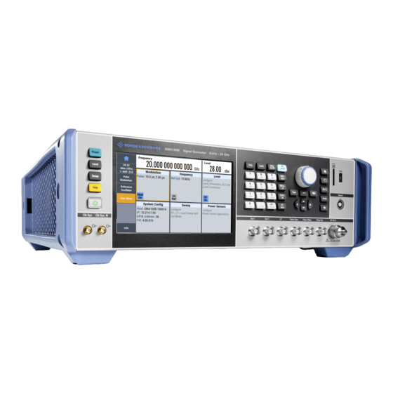
2.2.1 Front Panel Tour This section provides an overview of the control elements at the front panel of the R&S SMA100B. Most of the connectors are at the rear panel and are described in Chapter 2.2.2, "Rear Panel Tour", on page 40. - Page 48 ® Getting Started R&S SMA100B Instrument Tour Figure 2-1: Front panel view of the R&S SMA100B RF Signal Generator with height unit 2HU (option R&S SMAB-B92) 1 = Touchscreen 2 = Utility keys 3 = ON/STANDBY 4 = Function keys...
-
Page 49: Touchscreen
For instructions on cleaning the screen, see Chapter 13.1, "Cleaning", on page 487. 2.2.1.2 Utility Keys The utility keys set the R&S SMA100B to a defined state, and provide access to basic settings and information on assistance. User Manual 1178.3834.02 ─ 03... -
Page 50: On/Standby
® Getting Started R&S SMA100B Instrument Tour Table 2-1: Utility keys Utility Key Assigned functions PRESET Sets the instrument to a defined state LOCAL Switches from remote control to local (manual) control SETUP Accesses the general instrument settings HELP Displays context-sensitive help text 2.2.1.3... -
Page 51: Navigation Controls
® Getting Started R&S SMA100B Instrument Tour Type of key Description Sign key Changes the sign of a numeric parameter. In the case of an alphanu- meric parameter, inserts a "-" at the cursor position. Unit keys These keys add the selected unit to the entered numeric value and com- plete the entry. -
Page 52: Navigation Keys
® Getting Started R&S SMA100B Instrument Tour Navigation Keys As an alternative to the rotary knob or the touchscreen, you can use the navigation keys to navigate through dialog boxes, diagrams, or tables. Table 2-5: Navigation keys Type of key... -
Page 53: Sd Card Slot
SENSOR Connector for R&S NRP sensors. The R&S SMA100B supports the use of R&S NRP power sensors in various ways including the use as a power viewer. A power sensor is connected to the R&S SMA100B by inserting the male connector. -
Page 54: Pulse Signal Connectors
The application notes are available on the Internet and provide additional information on care and handling of RF connectors. Rohde & Schwarz offers appropriate torque wrenches for various connectors. For ordering information, see the R&S SMA100B data sheet or product brochure. 2.2.1.12 Pulse Signal Connectors Pulse Sync Output signal for synchronizing the pulse generator signal. -
Page 55: Clock Synthesizer Connectors
This section provides an overview of the connectors at the rear panel of the instrument. For technical data of the connectors, refer to the data sheet. Figure 2-4: Rear panel view of the R&S SMA100B RF Signal Generator with height unit 2HU (option R&S SMAB-B92) -
Page 56: Connectors
Getting Started R&S SMA100B Instrument Tour Figure 2-5: Rear panel view of the R&S SMA100B RF Signal Generator with height unit 3HU (option R&S SMAB-B93) 1 = IEC 625/IEEE 488 connector 2 = USB IN connector (type micro-B) 3 = LAN connector... - Page 57 Chapter 2.1.2, "Connecting USB Devices", on page 25. The LAN interface can be used to connect the R&S SMA100B to a local network for remote control, remote operation, and data transfer. For details, see Chapter 2.1.3, "Setting Up a Network (LAN) Connection",...
-
Page 58: Trying Out The Instrument
19" rack. 2.3 Trying Out the Instrument This chapter introduces the first steps with the R&S SMA100B. It shows how to oper- ate and configure the instrument using simple examples. The complete description of the functionality and its usage is given in the R&S SMA100B user manual. Basic instru- ment operation is described in Chapter 2.4, "Instrument... -
Page 59: Generating An Unmodulated Carrier
We start to generate a simple unmodulated signal. In this example, the R&S SMA100B can be in its minimal configuration. 1. On the R&S SMA100B front panel, press the PRESET key to set a defined initial instrument state. 2. Set the frequency: a) In the "Status Bar", tap the "Frequency"... - Page 60 Trying Out the Instrument The blue colored "RF On" icon indicates that the RF output is activated. The R&S SMA100B provides the 6 GHz signal at the RF A connector at the front panel. Figure 2-6: Generating an unmodulated signal...
-
Page 61: Generating An Rf Frequency Sweep Signal
Try out the front panel keys ► Use the FREQ, LEVEL, and RF ON/OFF key on the front panel. ® Connect RF of the R&S SMA100B to a signal analyzer, for example R&S FSW, to dis- play the generated signal. - Page 62 ® Getting Started R&S SMA100B Trying Out the Instrument a) Select "Mode > Auto" to run the sweep continuously. b) Select "Shape > Sawtooth" to set the waveform shape of the sweep signal. c) Select "Spacing > Linear", to determine the calculation method for the fre- quency shift of a step.
-
Page 63: Saving And Recalling Settings
9. To activate the RF signal output, select "Level" > "RF On". Figure 2-7: Generating a frequency sweep signal The frequency display indicates the frequencies of the running sweep. The R&S SMA100B provides the 6 GHz signal at the RF connector at the front panel. 2.3.3 Saving and Recalling Settings To restore the results of our measurements later, we save the instrument settings in a file. - Page 64 ® Getting Started R&S SMA100B Trying Out the Instrument 4. Tap the "Filename", use the on-screen keyboard, and enter MyTestSignal. 5. Tap the "Save" button. The file MyTestSignal.savrcltxt is stored in the default direc- tory /var/user/. To load saved instrument settings You can restore the settings to the instrument at any time using the settings file.
- Page 65 ® Getting Started R&S SMA100B Trying Out the Instrument 5. Tap the "Recall" button. All instrument settings are restored and the display resembles Chapter 2.3.2, "Gen- erating an RF Frequency Sweep Signal", on page 46, which shows the instrument display right before the settings were saved.
-
Page 66: Instrument Control
All changed parameters are highlighted. See also Chapter 9, "File and Data Management", on page 188. 2.4 Instrument Control This chapter provides an overview on how to work with the R&S SMA100B. It covers the following topics: User Manual 1178.3834.02 ─ 03... -
Page 67: Possible Ways To Operate The Instrument
"Remote Operation over VNC", on page 61. 2.4.2 Means of Manual Interaction For the manual interaction with the R&S SMA100B, you have several methods that you can use as an alternative to perform a task: ● Touchscreen: Touchscreen operation is the most direct way to interact. Almost all control ele- ments and actions on the screen are based on the standard operating system con- cept. -
Page 68: Understanding The Display Information
The status bar at the top of the screen indicates the RF frequency and the level of the output signal provided to the DUT. You can set both parameters directly here. 2.4.3.2 Tile Diagram The tile diagram is the main entry to the settings of the R&S SMA100B. User Manual 1178.3834.02 ─ 03... -
Page 69: Taskbar
® Getting Started R&S SMA100B Instrument Control Tile Access to: ● "Modulation" Analog and pulse modulation settings ● Built in LF generator ● "System Config" "Save/Recall": settings for saving and loading instrument configurations ● "Remote access": Network and emulation settings. -
Page 70: Additional Display Characteristics
® Getting Started R&S SMA100B Instrument Control Active dialogs Indicates the dialog name of each active dialog in a separate button. "Info" key Provides access to status and error messages. Note: The warning symbol signifies a permanent error message. 2.4.3.4... -
Page 71: Accessing The Functionality
® Getting Started R&S SMA100B Instrument Control 2.4.4 Accessing the Functionality All functionalities are provided in dialog boxes as known from computer programs. You can control the instrument intuitively with the touchscreen. This section provides an overview of the accessing methods. -
Page 72: Entering Data
® Getting Started R&S SMA100B Instrument Control To open a dialog box ► Perform one of the following actions: ● Tap the required tile, and then the menu entry. ● Tap the minimized view (button) on the taskbar. Some of the utility keys access a dedicated dialog, too. -
Page 73: Entering Numeric Parameters
® Getting Started R&S SMA100B Instrument Control 2.4.5.1 Entering Numeric Parameters To enter values with the on-screen keypad If a field requires numeric input, the keypad provides only numbers. The provided units correspond to the units of the parameter. 1. Enter the numeric value. -
Page 74: Getting Information And Help
® Getting Started R&S SMA100B Instrument Control 2.4.6 Getting Information and Help In some dialog boxes, graphics are included to explain the way a setting works. For further information, you can use the following sources: ● Tooltips give the value range of the parameter. -
Page 75: Remote Control
The corresponding help topic is displayed. 2.4.7 Remote Control In addition to working with the R&S SMA100B interactively, located directly at the instrument, it is also possible to operate and control it from a remote PC. The R&S SMA100B supports various methods for remote control: ●... -
Page 76: Remote Operation Over Vnc
Thus, remote operation of the instrument is possible. Instrument control from a remote computer To access the basic utility functions of the R&S SMA100B, perform a right mouse click on the block diagram and select "Key Emulation". A key panel to the right of the block diagram gives access to the utility functions provi- ded by the front panel keys. -
Page 77: Rf Signal Configuration
RF signal. In addition, the R&S SMA100B supports R&S NRP power sensors. Power sensors can be used to monitor the output level in the generator and to determine the level correc- tion values for user correction lists. -
Page 78: Activating Rf Signal Output
® RF Signal Configuration R&S SMA100B How to Set the Frequency and Level Generates RF signal based on a list of predefined frequency and level values pairs and step widths. Chapter 5, "Varying the RF Signal in List or Sweep Mode",... - Page 79 The R&S SMA100B generates the signal without the downstream parameters, but con- siders all additional parameters concerning the frequency and level, like frequency off- set and multiplication factor, or user correction. Any of these cases is indicated by a dedicated icon, displayed in the "Frequency"...
-
Page 80: Rf Frequency Settings
® RF Signal Configuration R&S SMA100B RF Frequency Settings 3.3 RF Frequency Settings Access: 1. Select "Frequency" > "Frequency". 2. Observe the information on the home screen, "Frequency" tile. The "Frequency" tile indicates the reference frequency, current frequency offset and multiplier values, and phase offset value. - Page 81 The "Frequency" value displayed in the status bar is the resulting frequency, as it is at the output of the downstream instrument. The frequency at the R&S SMA100B RF out- put is not changed. "RF frequency and level display with a downstream instrument"...
-
Page 82: Rf Level Settings
The "Frequency" value displayed in the status bar is the resulting frequency, as it is at the output of the downstream instrument. The frequency at the R&S SMA100B RF out- put is not changed. "RF frequency and level display with a downstream instrument"... - Page 83 ® RF Signal Configuration R&S SMA100B RF Level Settings In the "RF Level" dialog, you can configure the offset-free level, the level limit, and the step width for varying the level with the rotary knob. 2. Select "User Variation" to set the step width to be used when setting the RF level using the rotary knob.
-
Page 84: Rf State/Rf On
® RF Signal Configuration R&S SMA100B RF Level Settings The "Level" tile indicates the level limit, the user correction status and current cor- rection value, current setting characteristics incl. mode. The remote commands required to define the settings are described in Chap- ter 12.15.10, "SOURce:POWer... -
Page 85: Limit
The "Level" value displayed in the status bar is the resulting level, as it is at the output of the downstream instrument. The level at the R&S SMA100B RF output is not changed. "RF frequency and level display with a downstream instrument"... -
Page 86: Mode
® RF Signal Configuration R&S SMA100B RF Level Settings "Strictly Monotone" Executes signal level changes monotonically increasing or decreas- ing. The setting makes sure that increasing the level value exclusively results in an increased output level, and vice versa. All electronic switches, which might affect the monotonicity are fixed. -
Page 87: Rf Phase Settings
® RF Signal Configuration R&S SMA100B RF Phase Settings Readjust Recalculates and adjusts the internal switch positions of the RF chain according to the current level. Remote command: on page 435 [:SOURce<hw>]:POWer:ALC:SONCe User Variation Defines and activates a user-defined step width for varying the RF frequency or RF level with the rotary knob. - Page 88 ® RF Signal Configuration R&S SMA100B RF Phase Settings The remote commands required to define the settings are described in Chap- ter 12.15.9, "SOURce:PHASe Subsystem", on page 432. Settings Delta Phase........................73 Reset Delta Phase Display................... 73 Delta Phase Sets the phase of the RF signal.
-
Page 89: Analog Modulations
The three basic modulation types FM, AM and PhiM for example, vary one property of the carrier proportional to the instantaneous amplitude of the modulating signal. Signal sources If fully equipped, the R&S SMA100B modulates signals from the following sources: ● Internal modulation source –... - Page 90 ® Analog Modulations R&S SMA100B Modulation Types and Signal Sources A further LF generator for use as a second modulation source or to generate a noise modulation signal The noise generator supplies white noise with selectable bandwidth and level distribution.
-
Page 91: Activating Analog Modulations
® Analog Modulations R&S SMA100B Modulation Settings Interactions and characteristics ● Some modulations exclude each other and cannot be performed simultaneously. Chapter 4.8.1, "Simultaneous Operation of Several Modulations", on page 108 ● The settings of the modulation signal affect all analog modulations that use an internal modulation source. -
Page 92: Pulse Modulation
® Analog Modulations R&S SMA100B Modulation Settings 4.4.1 Pulse Modulation Option: see Chapter 4.1, "Required Options", on page 74. Access: ► Select "Modulation" > "Pulse Modualtion". The "Pulse Modulation" dialog contains all parameters required to configure pulse modulation and pulse signal generation. -
Page 93: Fm, Phim And Fm Modulation Settings
® Analog Modulations R&S SMA100B Modulation Settings Source Selects between the internal "Pulse Generator" or an "External" pulse signal for the modulation. "Pulse Generator" Selects the internal generator. Pulse Generator. "External" Modulation source is fed to the input connector. "Signal sources"... -
Page 94: Source State
® Analog Modulations R&S SMA100B Modulation Settings Access: ► Select "Modulation" > "Amplitude Modulation/Frequency Modualtion/Phase Mod- ualtion". The "FM", "Φ" and "AM" tabs contain the parameters per modulation type. Source State..........................79 Source...........................80 settings........................80 └ Deviation......................80 └ Ratio Path2/Path1...................80 └ Mode....................... 81 PhiM.......................... -
Page 95: Source
® Analog Modulations R&S SMA100B Modulation Settings Remote command: on page 368 [:SOURce<hw>]:AM<ch>:STATe on page 373 [:SOURce<hw>]:FM<ch>:STATe on page 376 [:SOURce<hw>]:PM<ch>:STATe Source Selects the LF signal source. You can vary the signal sources for each of the modulations. "LF Generator1/2"... -
Page 96: Mode
® Analog Modulations R&S SMA100B Modulation Settings Mode ← FM settings Selects the mode of the frequency modulation. "High Bandwidth" The maximum range for modulation bandwidth is available. "Low Noise" Phase modulation with phase noise and spurious characteristics close to CW mode. The range for modulation bandwidth and FM devi- ation is reduced (see data sheet). -
Page 97: Pulse Generator
® Analog Modulations R&S SMA100B Modulation Settings "High Deviation" The maximum range for PhiM deviation is available. Phase noise is improved for low frequencies compared to the default mode. The range for modulation frequency is limited (see data sheet). This mode is suitable for low modulation frequencies and/or high PhiM deviation. -
Page 98: Pulse Generator > General Settings
® Analog Modulations R&S SMA100B Modulation Settings The "Pulse Generator" tab contains the settings for creating the pulse modulation signal internally. ● Pulse Generator > General Settings............... 83 ● Pulse Generator > Pulse Train Settings..............87 ● Import/Export List Files................... 91 4.4.3.1... - Page 99 ® Analog Modulations R&S SMA100B Modulation Settings "Single" Generates a single pulse in one pulse period. "Double" Generates two pulses in one pulse period. "Train" Option: R&S SMAB-K27 Generates a user-defined pulse train. Chapter 4.4.3.2, "Pulse Generator > Pulse Train Settings",...
- Page 100 ® Analog Modulations R&S SMA100B Modulation Settings "Ext Triggered" Generates the signal each time an external trigger event occurs. Example: Generation of single pulse signal ("Pulse Mode = Sin- gle") using "Trigger Mode = Ext Triggered" = External trigger signal input with "Trigger Input Polarity = Normal" (the positive...
- Page 101 ® Analog Modulations R&S SMA100B Modulation Settings Δt = Typically 50 ns, see data sheet (trigger delay between the trigger and the sync signal start) delay = "Double Pulse Delay = 200 ns"; the first pulse starts without a delay = "Double Pulse Width = 100 ns"...
-
Page 102: Pulse Generator > Pulse Train Settings
® Analog Modulations R&S SMA100B Modulation Settings Double Pulse Width Sets the width of the second pulse. Remote command: on page 379 [:SOURce<hw>]:PULM:DOUBle:WIDTh Pulse Delay Sets the pulse delay. The pulse delay determines the time that elapses after a trigger event before pulse modulation starts. - Page 103 ® Analog Modulations R&S SMA100B Modulation Settings 2. Select "Pulse Train Data". 3. Select an existing file or select "New" to create one. 4. Define the filename. Select "Edit Pulse Train Data", if the file is empty or to control and change the val- ues.
- Page 104 ® Analog Modulations R&S SMA100B Modulation Settings Pulse train ASCII file format Files describing pulse trains are simple files in text or comma-separated value (CSV) file format. The filename is user-definable; the file extension is *.csv or *.txt. The file contains a list of pulse definition values, one row per pulse; a new line indicator separates the pulses.
- Page 105 ® Analog Modulations R&S SMA100B Modulation Settings "Count" Sets the number of repetitions of an "On-/ Off-Time" value pair. Pulses with "Count = 0" are ignored. Use this method to skip value pairs temporarily, without deleting them from the table.
-
Page 106: Import/Export List Files
® Analog Modulations R&S SMA100B Modulation Settings The settings are interdependent; the affected parameters change accordingly if you set a value. To fill the table, select "Fill". Note: Save a list only after filling all columns and rows, otherwise the entries are lost. -
Page 107: Settings Mode
® Analog Modulations R&S SMA100B Modulation Settings 2. Select "Import/Export". Figure 4-1: Im-/Export dialog (example with UCOR settings) The "Import/Export" dialog contains all functions and settings to import externally created list data or to export it accordingly. You can process and store a list in the formats *.txt (ASCII), or *.csv (plain text with identical sequence of fields). -
Page 108: Select Source/Select Destination
® Analog Modulations R&S SMA100B Modulation Settings "Decimal Sets "Point" (dot) or "Comma" as the decimal separator used in the Point" ASCII data with floating-point numerals. "Column Separator" Sets the separator between the columns in an ASCII table. Available are: "Tab", "Semicolon", "Comma" or "Space". -
Page 109: Pulse Graph
® Analog Modulations R&S SMA100B Modulation Settings Import / Export Imports or exports the selected data list file, depending on the current mode. Remote command: on page 427 [:SOURce<hw>]:LIST:DEXChange:EXECute on page 395 [:SOURce<hw>]:CORRection:DEXChange:EXECute on page 388 [:SOURce<hw>]:PULM:TRAin:DEXChange:EXECute 4.4.4 Pulse Graph Option: see Chapter 4.1, "Required... -
Page 110: Pulse External/Trigger Settings
® Analog Modulations R&S SMA100B Modulation Settings 4.4.5 Pulse External/Trigger Settings Access: ► Select "Modulation" > "Pulse Modulation > Pulse External /Trigger". The dialog comprises the characteristics of the PULSE EXT connector. This connector is common for the pulse generator and the pulse modulator. For an overview, see "Input and output connectors"... -
Page 111: Fm, Am And Phim Modulation Sources
® Analog Modulations R&S SMA100B Modulation Settings Show Connector Accesses a dialog that displays the physical location of the selected connector on the front/rear panel of the instrument. 4.4.6 FM, AM and PhiM Modulation Sources Access: ► Select "Modulation > Modulation Sources". - Page 112 ® Analog Modulations R&S SMA100B Modulation Settings The internal LF signal can be used as modulation signal source for any of the ana- log modulations. The LF signal applies to all modulations which use the internal modulation signal. Therefore, any modification of the LF signal influences immedi- ately all currently active modulations.
- Page 113 ® Analog Modulations R&S SMA100B Modulation Settings "Pulse" 1 = Pulse period 2 = Pulse width "Triangle" 1 = Triangle period 2 = Triangle rise "Trapezoid" 1 = Trapezoid period 2 = Trapezoid rise 3 = Trapezoid fall 4 = Trapezoid high...
- Page 114 ® Analog Modulations R&S SMA100B Modulation Settings The period of sine signals is calculated from the selected Frequency Remote command: on page 412 [:SOURce<hw>]:LFOutput<ch>:SHAPe:TRAPeze:PERiod on page 412 [:SOURce<hw>]:LFOutput<ch>:SHAPe:TRIangle:PERiod on page 410 [:SOURce<hw>]:LFOutput<ch>:SHAPe:PULSe:PERiod Pulse Width Sets the pulse duration of the generated pulse signal.
-
Page 115: Source > External Settings
® Analog Modulations R&S SMA100B Modulation Settings 4.4.6.2 Source > External Settings Access: ► Select "Modulation" > "Modulation Sources > External". The "External" settings section contains all parameters required to configure the signal of an externally supplied LF signal. Settings Coupling (AC/DC)....................... -
Page 116: Source > Noise Generator Settings
® Analog Modulations R&S SMA100B Modulation Settings Remote command: on page 406 [:SOURce]:LFOutput<ch>:BANDwidth? Show Connector Accesses a dialog that displays the physical location of the selected connector on the front/rear panel of the instrument. 4.4.6.3 Source > Noise Generator Settings Access: ►... -
Page 117: Lf Signal Output Settings
® Analog Modulations R&S SMA100B Modulation Settings Bandwidth range Step size 100 kHz to 1 MHz 100 kHz 1 MHz to 5 MHz 1 MHz 5 MHz to 10 MHz 5 MHz Remote command: on page 429 [:SOURce<hw>]:NOISe:BANDwidth|BWIDth on page 430 [:SOURce<hw>]:NOISe:BWIDth:STATe... - Page 118 ® Analog Modulations R&S SMA100B Modulation Settings State Activates the output of the LF signal. Remote command: on page 409 [:SOURce]:LFOutput<ch>[:STATe] Source Selects the signal to be output at the LF connector. Use the "Show Connector" function to find out where this connector is located.
-
Page 119: Overview
® Analog Modulations R&S SMA100B Modulation Settings Noise Density ← Noise Generator Indicates the level of the noise signal for a bandwidth of 1 Hz (relative). Remote command: on page 430 [:SOURce<hw>]:NOISe:LEVel:RELative? Noise Level ← Noise Generator Indicates the level of the noise signal per Hz within the total bandwidth (absolute). -
Page 120: How To Generate An Amplitude Modulated Signal
® Analog Modulations R&S SMA100B How to Generate an Amplitude Modulated Signal Access: ► Select "Modulation" > "Modulation Sources > Overview". Blue color = Active modulation (AM and FM/PM) Gray color = Inactive modulation Thick line = Routing of the active modulation (FM/PM) Dash line = Inactive modulation "LF Out"... -
Page 121: How To Generate A Pulse Modulated Signal
® Analog Modulations R&S SMA100B How to Generate a Pulse Modulated Signal 2. In the status bar, set "Frequency = 2 GHz". 3. Set "Level = -20 dBm". Configuring the modulation signal (LF generator) 1. Select "Modulation" > "Modulation Source". -
Page 122: How To Generate A Pulse Train Modulated Signal
® Analog Modulations R&S SMA100B How to Generate a Pulse Train Modulated Signal Enabling pulse modulation 1. Select the "Pulse Modulation" tab. 2. Set "State = On". 3. Set "Level > RF ON" to enable signal output. 4.7 How to Generate a Pulse Train Modulated Signal The following example uses the internal pulse generator. -
Page 123: References
® Analog Modulations R&S SMA100B References 2. Set "State = On". 3. Set "Level > RF ON" to enable signal output. 4.8 References 4.8.1 Simultaneous Operation of Several Modulations The table shows the modulations and operating modes that can be activated simulta- neously (+) or which deactivate each other (-). -
Page 124: Varying The Rf Signal In List Or Sweep Mode
A signal generated with varying parameters scans a certain range of varying values of a parameter, with defined start and end points, and can be arbitrarily repeated. The R&S SMA100B supports two basic methods: ● Sweep mode The instrument generates an RF signal which varies its frequency or level values cyclically between the start and end values. -
Page 125: Signal Generation And Triggering In The Sweep And List Modes
® Varying the RF Signal in List or Sweep Mode R&S SMA100B Signal Generation and Triggering in the Sweep and List Modes Figure 5-2: Schematic representation of a signal generated in list mode (global dwell time) This mode is especially useful in high-speed measurements with fast changing fre- quency and level settings. - Page 126 ® Varying the RF Signal in List or Sweep Mode R&S SMA100B Signal Generation and Triggering in the Sweep and List Modes vating the mode and the generation of the signal when a trigger event occurs. The rele- vant parameters and settings are briefly explained to each mode.
- Page 127 ® Varying the RF Signal in List or Sweep Mode R&S SMA100B Signal Generation and Triggering in the Sweep and List Modes Table 5-1: Cross-reference between manual and remote control in Auto mode (Sweep/List) Manual control mode: Remote commands "Auto"...
- Page 128 ® Varying the RF Signal in List or Sweep Mode R&S SMA100B Signal Generation and Triggering in the Sweep and List Modes ● Switches automatically to the next step when the Dwell time has elapsed. ● Stops signal generation at the set end value and waits for the subsequent trigger event.
- Page 129 ® Varying the RF Signal in List or Sweep Mode R&S SMA100B Signal Generation and Triggering in the Sweep and List Modes Step / Extern Step mode (Sweep/List) Figure 5-5: Step / Extern Step mode (sweep / list ) ●...
- Page 130 ® Varying the RF Signal in List or Sweep Mode R&S SMA100B Signal Generation and Triggering in the Sweep and List Modes Table 5-3: Cross-reference between manual and remote control in Step / Extern Step modes (Sweep/ List) Manual control mode: Remote commands "Step / Extern Step"...
- Page 131 ® Varying the RF Signal in List or Sweep Mode R&S SMA100B Signal Generation and Triggering in the Sweep and List Modes ● Switches automatically to the next sweep step when the Dwell time has elapsed. If the end value is reached, signal generation continues with the next sweep cycle.
- Page 132 ® Varying the RF Signal in List or Sweep Mode R&S SMA100B Signal Generation and Triggering in the Sweep and List Modes You can arbitrarily select a value within the range of the start and stop values by setting the frequency, power or index using the corresponding remote control com- mand.
-
Page 133: About Sweep Mode
Configuration and operation of sweep mode signals ● The R&S SMA100B generates a sweep signal by varying one of the following parameters: the RF frequency, the LF frequency or the RF level. ● In all sweep modes, you can perform a complete sweep cycle once, repeat the cycle continuously or step through it gradually. - Page 134 ® Varying the RF Signal in List or Sweep Mode R&S SMA100B About Sweep Mode Variable Description Frequency offset OFFSet Start frequency of the sweep range STARt End frequency of the sweep range STOP Current sweep frequency Next, subsequent sweep frequency...
-
Page 135: About List Mode
® Varying the RF Signal in List or Sweep Mode R&S SMA100B About List Mode Sweep steps In the following, you see how the sweep steps are calculated depending on the defined spacing mode. The formulas show a frequency sweep, but apply to the level settings in the same way. -
Page 136: Significant Parameters And Functions
® Varying the RF Signal in List or Sweep Mode R&S SMA100B Significant Parameters and Functions Creating and handling lists List files can be created in the following ways: ● Internally Use the build-in table editor with columns for the frequency-level values pairs and the dwell time. - Page 137 Live list processing mode The R&S SMA100B generates the signal directly from the value pairs in the database, and adjusts the hardware settings accordingly. The current instrument state and thus any change during the signal generation directly affects the RF signal. The temporary memory is not used.
-
Page 138: Sweep Mode Settings
® Varying the RF Signal in List or Sweep Mode R&S SMA100B Sweep Mode Settings You can conveniently modify parameters like modulation settings during run-time. Learning list mode data is not required. Impacts like temperature drift are also consid- ered immediately. - Page 139 ® Varying the RF Signal in List or Sweep Mode R&S SMA100B Sweep Mode Settings Settings State (RF frequency sweep)..................124 State (RF level sweep)....................124 State (LF frequency sweep)..................124 Current Frequency...................... 125 Current Level.......................125 Mode........................... 125 Retrace........................126 Shape .........................126 Spacing........................
- Page 140 ® Varying the RF Signal in List or Sweep Mode R&S SMA100B Sweep Mode Settings In the "Sources" tab of the analog modulations, the instrument shows the current state of the LF frequency sweep. Note: Active sweep mode deactivates other sweeps or lists and vice versa.
- Page 141 ® Varying the RF Signal in List or Sweep Mode R&S SMA100B Sweep Mode Settings on page 483 :TRIGger<hw>:FSWeep:SOURce on page 484 :TRIGger<hw>:PSWeep:SOURce on page 483 :TRIGger<hw>:LFFSweep:SOURce Retrace For "Shape = Sawtooth" and "Mode = Single/External Single", activates that the signal changes to the start value while it is waiting for the next trigger event.
- Page 142 ® Varying the RF Signal in List or Sweep Mode R&S SMA100B Sweep Mode Settings "Triangle" The sweep runs from start to stop value and back, i.e. the shape of the sweep resembles a triangle. Each subsequent sweep starts at the start frequency.
-
Page 143: Frequency Range Settings
® Varying the RF Signal in List or Sweep Mode R&S SMA100B Sweep Mode Settings Trigger signal is expected at the INST TRIG connector. "Positive" Activates the rising edge of the trigger signal. "Negative" Activates the falling edge of the trigger signal. - Page 144 ® Varying the RF Signal in List or Sweep Mode R&S SMA100B Sweep Mode Settings Settings Start Frequency/Stop Frequency ................129 Center Frequency ...................... 129 Span..........................129 Spacing........................129 Step Linear/Step Logarithmic ..................129 Start Frequency/Stop Frequency Defines the frequency sweep range by setting the start and end values.
-
Page 145: Level Range Settings
® Varying the RF Signal in List or Sweep Mode R&S SMA100B Sweep Mode Settings Chapter 5.2.1, "Correlating Parameters in Sweep Mode", on page 118. "Step Linear" The step width is a constant value in Hz. "Step Logarithmic" The step width is determined logarithmically in %, i.e. as a constant fraction of the current frequency. -
Page 146: List Mode Settings
® Varying the RF Signal in List or Sweep Mode R&S SMA100B List Mode Settings Remote command: n.a. Step Applies to "RF Level Sweep" mode. Sets the step width for the level sweep steps. The step width is specified logarithmically in dB, i.e. as constant fraction of the current level. -
Page 147: General Settings
® Varying the RF Signal in List or Sweep Mode R&S SMA100B List Mode Settings 5.6.1 General Settings Access: ► Select "Sweep" > "List mode". In the "General" tab, you can configure the trigger and dwell time modes for list processing and activate signal generation. - Page 148 ® Varying the RF Signal in List or Sweep Mode R&S SMA100B List Mode Settings Remote command: on page 421 [:SOURce<hw>]:LIST:INDex Mode Selects the mode for list processing. For detailed information on the sweep modes and the triggering, see Chapter 5.1, "Sig- nal Generation and Triggering in the Sweep and List Modes",...
-
Page 149: List Mode Data Settings
® Varying the RF Signal in List or Sweep Mode R&S SMA100B List Mode Settings "Live" Generates the signal directly from the database. The instrument reads the pairs of values from the list, calculates the hardware settings and generates the signal immediately. -
Page 150: Import/Export Settings
® Varying the RF Signal in List or Sweep Mode R&S SMA100B List Mode Settings Settings List Mode Data ......................135 Edit List Mode Data ....................135 List Range from/to ......................135 List Mode Data Accesses the standard "Select List" dialog for selecting, creating and editing a list file. - Page 151 ® Varying the RF Signal in List or Sweep Mode R&S SMA100B List Mode Settings 2. Select "List Mode Data" > "Im-/Export". The "Im-/Export" dialog provides the parameters for importing or exporting files with user data in standard ASCII *.txt or *.csv file format.
- Page 152 ® Varying the RF Signal in List or Sweep Mode R&S SMA100B List Mode Settings Remote command: on page 427 [:SOURce<hw>]:LIST:DEXChange:AFILe:EXTension on page 428 [:SOURce<hw>]:LIST:DEXChange:AFILe:SEParator:DECimal on page 428 [:SOURce<hw>]:LIST:DEXChange:AFILe:SEParator:COLumn on page 394 [:SOURce<hw>]:CORRection:DEXChange:AFILe:EXTension [:SOURce<hw>]:CORRection:DEXChange:AFILe:SEParator:DECimal on page 394 [:SOURce<hw>]:CORRection:DEXChange:AFILe:SEParator:COLumn on page 394 on page 386 [:SOURce<hw>]:PULM:TRAin:DEXChange:AFILe:EXTension...
-
Page 153: List Editor
® Varying the RF Signal in List or Sweep Mode R&S SMA100B List Editor 5.7 List Editor The "User Correction" and "List Mode" dialogs provide a build-in list editor for defining frequency/level value pairs. The list editors in these two dialogs are similar. The following description shows the "List Data Editor". - Page 154 ® Varying the RF Signal in List or Sweep Mode R&S SMA100B List Editor Edit List Mode Data Table with correction or list values. "Frequency /Hz" Sets the frequency values. Remote command: on page 421 [:SOURce<hw>]:LIST:FREQuency on page 390 [:SOURce<hw>]:CORRection:CSET:DATA:FREQuency "Power /dBm"...
-
Page 155: How To Generate A Signal In List Or Sweep Mode
® Varying the RF Signal in List or Sweep Mode R&S SMA100B How to Generate a Signal in List or Sweep Mode The settings are interdependent; the affected parameters change accordingly if you set a value. To fill the table, select "Fill". - Page 156 ® Varying the RF Signal in List or Sweep Mode R&S SMA100B How to Generate a Signal in List or Sweep Mode Example: Fast changing frequency and level settings in list mode The following example shows you how to generate an amplitude modulated RF signal based on list mode data.
- Page 157 ® Varying the RF Signal in List or Sweep Mode R&S SMA100B How to Generate a Signal in List or Sweep Mode During list processing, the generator displays no frequency and level values in the status bar, but you can check the following parameters.
-
Page 158: Improving Level Performance
Sensors", on page 158 6.1 Attenuator The R&S SMA100B is equipped with an electronic step attenuator unit that supports RF wear-free level setting. About the attenuator The attenuator is an electronic component which enables you to vary the amplitude of the RF signal. -
Page 159: Attenuator Settings
® Improving Level Performance R&S SMA100B Attenuator ● DUT tests under low signal to noise conditions Low output power is suitable to test the behavior of a DUT under low signal to noise conditions. ● Uninterrupted level settings with constant VSWR A fix attenuation value is required for obtaining uninterrupted level settings with constant VSWR. -
Page 160: Reverse Power Protection
436 [:SOURce<hw>]:POWer:ATTenuation:RFOFf:MODE 6.1.2 Reverse Power Protection The R&S SMA100B is equipped against overloading by an external signal applied to the RF output. The reverse power protection is tripped when the power of signals reflected from the load or external signals applied to the RF output becomes too high. A relay opens and interrupts the internal connection to the RF output. -
Page 161: Alc - Automatic Level Control
If pulse modulation is applied, this mode ensures fast level setting even with nar- row pulses at low repetition rate. The R&S SMA100B displays the level control setting as a status message in the info line. User Manual 1178.3834.02 ─ 03... -
Page 162: Alc Settings
® Improving Level Performance R&S SMA100B ALC - Automatic Level Control 6.2.1 ALC Settings Access: ► Select "Level" > "Automatic Level Control". In the "ALC" dialog, you can configure the settings for the automatic level control of the RF signal to achieve optimal accuracy. -
Page 163: User Correction
434 [:SOURce<hw>]:POWer:ALC:DSENsitivity 6.3 User Correction The R&S SMA100B supports a correction function to compensate external losses, as for example caused by the RF cable, to achieve a precise target input level at the DUT. About UCOR User correction (UCOR) is a method that determines the external level loss over a fre- quency range in advance. -
Page 164: User Correction Settings
® Improving Level Performance R&S SMA100B User Correction The file contains a list of correction values, one row per frequency and level pair; a new line indicator separates the correction values. For file handling, use the standard functions in the "File Manager", see Chapter 9.8,... - Page 165 ® Improving Level Performance R&S SMA100B User Correction 4. Select "State > On". The "UCOR" dialog contains all settings for creating and handling files with user- defined level correction values. The remote commands required to define these settings are described in Chap- ter 12.15.2, "SOURce:CORRection...
-
Page 166: List Editor
® Improving Level Performance R&S SMA100B User Correction ● Use the general editor function to create internally new file or to edit an existing one. ● Use the standard file manager function to load externally created files to the instru- ment. - Page 167 ® Improving Level Performance R&S SMA100B User Correction All values in one row have to be defined. Rows with missing values are ignored and not saved. Values of incomplete rows get lost. If you use global dwell time in list mode, consider also the following: ●...
- Page 168 ® Improving Level Performance R&S SMA100B User Correction Fill with Sensor ← Data handling keys In "UCOR" mode, opens a dialog to configure the settings for automatic filling of user correction data with an R&S NRP power sensor Chapter 6.3.3, "Fill with Sensor",...
-
Page 169: Fill With Sensor
® Improving Level Performance R&S SMA100B User Correction 6.3.3 Fill with Sensor Access: 1. Select "Level" > "User Correction". 2. Select "User Cor. Data > navigate to the file *.ucor > Select". 3. Select "Edit Cor. Data > Edit > Fill With Sensor". -
Page 170: Import/Export List Files
® Improving Level Performance R&S SMA100B User Correction Indicates the used list. ● "Include Zeroing" Performs a zeroing procedure before acquiring the user correction data to improve precision. No signal may be applied to the sensor during zeroing. RF output is temporarily switched off during that time. - Page 171 ® Improving Level Performance R&S SMA100B User Correction 2. Select "Import/Export". Figure 6-1: Im-/Export dialog (example with UCOR settings) The "Import/Export" dialog contains all functions and settings to import externally created list data or to export it accordingly. You can process and store a list in the formats *.txt (ASCII), or *.csv (plain text with identical sequence of fields).
- Page 172 ® Improving Level Performance R&S SMA100B User Correction "Decimal Sets "Point" (dot) or "Comma" as the decimal separator used in the Point" ASCII data with floating-point numerals. "Column Separator" Sets the separator between the columns in an ASCII table. Available are: "Tab", "Semicolon", "Comma" or "Space".
-
Page 173: Using Power Sensors
S-parameter correction and return the results to the generator. The R&S SMA100B works with any sensor of the R&S NRP series and can perform up to four power measurements simultaneously. Check the firmware version of the R&S NRP sensors regularly. Update the firmware, if necessary. -
Page 174: Nrp Sensor Mapping
On connection, the R&S SMA100B immediately starts the measurement of a detected R&S NRP power sensor. If you perform an instrument preset (PRESET key or *RST), the R&S SMA100B stops the measurements. The connection and the mapping of the power sensors remain, the measurements must be restarted. - Page 175 The detected sensors are characterized by the used protocol and the correspond- ing icon. In the "Mapping" column, you can assign the sensor to one of the availa- ble sensor channels. The list can contain several entries but the R&S SMA100B can only use up to four sensors simultaneously.
-
Page 176: Nrp Power Viewer
Remote command: on page 354 :SLISt:SCAN[:STATe] 6.4.3 NRP Power Viewer The R&S SMA100B features the power viewer function for measuring or monitoring signals with R&S NRP power sensors. 6.4.3.1 About The R&S SMA100B can perform up to four power measurements simultaneously. The measured signals can be the RF output power or other selected signal sources. - Page 177 ® Improving Level Performance R&S SMA100B Using Power Sensors Depending on the R&S NRP power sensor type, the manual setting of the filter length varies in resolution: ● Resolution = 1 for the R&S NRPxx family ● Resolution = 2 for R&S NRP-Zxx power sensors, with n = 1 to 16...
-
Page 178: Nrp Power Viewer Settings
® Improving Level Performance R&S SMA100B Using Power Sensors Related settings and functions ● Measurements-related settings, like results, filter, filter length: Chapter 6.4.3.2, "NRP Power Viewer Settings", on page 163 ● Sensor-specific information and sensor software update: Chapter 6.4.4, "NRP Info Update",... - Page 179 ® Improving Level Performance R&S SMA100B Using Power Sensors The "Overview" tab shows the list of detected sensors, and provides a separate tab per sensor. A sensor tab contains all parameters for configuring the sensor settings, like aver- age or peak display, reference source, filter and level offset.
- Page 180 ® Improving Level Performance R&S SMA100B Using Power Sensors └ Aperture Time....................168 └ S-Parameter ....................168 └ Enable Logging..................... 168 Sensor type and serial number Indicates the type and the serial number of a selected R&S NRP power sensor, and the channel the sensor is assigned to.
- Page 181 ® Improving Level Performance R&S SMA100B Using Power Sensors Remote command: on page 358 :SENSe<ch>[:POWer]:DISPlay:PERManent:STATe Display ← Display ← Sensor settings Sets the display of results on mean or peak power. Remote command: on page 358 :SENSe<ch>[:POWer]:DISPlay:PERManent:PRIority Use Frequency Of ← Sensor settings Selects the source for measurement.
- Page 182 ® Improving Level Performance R&S SMA100B Using Power Sensors "User" The filter length is defined manually, with the parameter Filter Length. As the filter length works as a multiplier for the time window, constant filter length results in a constant measurement time.
-
Page 183: Nrp Info Update
® Improving Level Performance R&S SMA100B Using Power Sensors Aperture Time ← Sensor settings If "Use Default Aperture Time > Off", defines the acquisition time per sensor. For example, to obtain a sufficient low average value, set the aperture time exactly to one modulation period. - Page 184 351. Settings Current Sensors......................169 Update.........................169 Current Sensors Shows the sensors that are connected to the R&S SMA100B with information on serial number, the revision state, and some characteristic features. Remote command: on page 363 :SENSe<ch>[:POWer]:TYPE? on page 363 :SENSe<ch>[:POWer]:SVERsion?
-
Page 185: How To Update The Sensor Firmware
3. Select "Downloads > Firmware" and the firmware provided for your sensor. 4. Save the firmware in the /var/user/temp/ directory. 5. Connect the sensor to the R&S SMA100B. 6. Select "System Config > Setup > Instrument Assembly > NRP Info/Update". -
Page 186: How To Calibrate The Power Level With An R&S Nrp Power Sensor
5. Close the dialog. To configure and calibrate the R&S NRP in the R&S SMA100B Provided the power sensor is connected to the R&S SMA100B and is assigned to a sensor channel, we recommend that you calibrate and configure the power sensor in the "NRP Power Viewer"... - Page 187 6. Select "State > On". 7. Close the dialog. To create user correction data with an R&S NRP and the R&S SMA100B We assume, that the power sensor is connected, assigned and ready for operation. 1. Select "Level" > "User Correction".
- Page 188 We assume that a user correction file is available in the user directory of the R&S SMA100B or on a memory stick or in a shared directory. If you have created and saved the file immediately before this step, the file is loaded in the "User Correction"...
- Page 189 ® Improving Level Performance R&S SMA100B How to Calibrate the Power Level with an R&S NRP Power Sensor 4. Load the file with "Select". 5. To view the file content, select "Edit User Cor. Data". 6. Select "UCOR Data > State > On" to apply the user correction values.
-
Page 190: Reference Oscillator
Using the Reference Frequency for Instruments Synchronization 7 Reference Oscillator The R&S SMA100B is equipped with an internal reference oscillator that generates a reference frequency of 1 GHz. It is used as internal reference source for the synthe- sizer. Alternatively, you can apply an external reference signal. The R&S SMA100B can process external reference frequency in the range 1 MHz to 100 MHz and the 1 GHz reference frequency. - Page 191 External Tuning Slope = "Low" Figure 7-1: Synchronizing instruments using the internal 10 MHz reference signal of the R&S SMA100B = External frequency control EFC,REF IN,REF OUT = Connectors In phase noise measurement systems, for example, you can additionally use the EFC (external frequency control) function and shift the frequency.
- Page 192 ® Reference Oscillator R&S SMA100B Using the Reference Frequency for Instruments Synchronization If the measurement requires higher PLL bandwidth, we recommend that you use the external FM modulation (DC coupling) in low noise mode. The FM-DC mode yields a fixed tuning sensitivity that is independent of the RF out- put frequency and corresponds to the selected FM deviation.
-
Page 193: Reference Frequency Settings
® Reference Oscillator R&S SMA100B Reference Frequency Settings ● Set the synchronization bandwidth according to the requirements of the applica- tion. Deriving 10 MHz form the external reference frequency 10 MHz reference frequency can be derived from the following external reference sig- nals: ●... - Page 194 ® Reference Oscillator R&S SMA100B Reference Frequency Settings In the "Reference Frequency" tab, you can select the signal source of the reference frequency and define the frequency of an external reference signal. 2. Observe the information on the home screen, "Frequency" tile.
- Page 195 ® Reference Oscillator R&S SMA100B Reference Frequency Settings Synchronization Bandwidth..................181 Nominal Synchronization Bandwidth................181 Minimum Locking Range.....................181 External Tuning Active....................181 External Tuning Slope....................181 Set to Default Calls the default settings. Remote command: on page 443 [:SOURce]:ROSCillator:PRESet Source Selects the reference frequency source.
- Page 196 ® Reference Oscillator R&S SMA100B Reference Frequency Settings Variable Reference Frequency Requires R&S SMAB-K704 Sets the variably settable external reference frequency. Remote command: on page 445 [:SOURce]:ROSCillator:EXTernal:FREQuency:VARiable Synchronization Bandwidth Selects the synchronization bandwidth for an external reference signal. The resulting bandwidth is indicated with the parameter Nominal Synchronization Bandwidth.
-
Page 197: Reference Output Settings
® Reference Oscillator R&S SMA100B Reference Output Settings Remote command: on page 444 [:SOURce]:ROSCillator:INTernal:TUNing:SLOPe 7.4 Reference Output Settings Access: 1. Select "Frequency" > "Reference Freq" 2. Select "Reference Output". In the "Reference Output" tab, you can set the reference frequency value at the output connectors. -
Page 198: Adjustments Settings
® Reference Oscillator R&S SMA100B Adjustments Settings Show Connector Accesses a dialog that displays the physical location of the selected connector on the front/rear panel of the instrument. 7.5 Adjustments Settings Access: 1. Select "Frequency" > "Reference Freq" 2. Select "Adjustment". -
Page 199: Clock Synthesis
® Clock Synthesis R&S SMA100B 8 Clock Synthesis The clock synthesis provides a separate system clock with a freely selectable fre- quency for test setups that require an additional clock reference. For example, in a test setup that uses an A/D converter, the required system clock for data sampling can be provided without the need of additional signal generator. - Page 200 ® Clock Synthesis R&S SMA100B 3. Observe the information on the home screen, "Clk Syn/Power Sens" tile. The "Clk Syn/Power Sens" tile indicates that clock synthesis is activated and gives an overview of the key parameters. Settings State ...........................185 Output Type........................
- Page 201 ® Clock Synthesis R&S SMA100B "Single-Ended/Differential Sine" Sine signals with user-definable amplitude. "Differential Square" Squared signal with fixed amplitude. "CMOS" CMOS-like signal with user-definable amplitude and limited frequency range. Remote command: on page 329 :CSYNthesis:OTYPe Frequency Sets the frequency of the generated clock signal.
- Page 202 ® Clock Synthesis R&S SMA100B Remote command: on page 330 :CSYNthesis:OFFSet:STATe DC Offset Sets the value of the DC offset for both clock synthesis signal outputs. Remote command: on page 330 :CSYNthesis:OFFSet Voltage Output Type = "CMOS", sets the high-level of the output signal.
-
Page 203: File And Data Management
About the File System 9 File and Data Management The R&S SMA100B uses files to save all instrument data. The instrument allows you to store and to load instrument settings, and to import and to export user data for pro- cessing in another instrument or later. -
Page 204: Accessing Files With User
The /var/volatile directory serves as a RAM drive and can be used to protect sensitive information. The data is available temporarily. If option R&S SMAB-B85 is installed, the R&S SMA100B maps the user directory to the removable memory. If a memory is mounted, user data is saved there. Otherwise user data is redirected to the volatile memory. - Page 205 They are reserved by the operating system. File extensions The R&S SMA100B distinguishes the files according to their extensions; each type of file is assigned a specific file content and also a specific file extension. The extension is usually of no consequence to you since access to the files occurs in the individual dialogs where only the relevant type of file is available.
-
Page 206: Restoring The (Default) Instrument Configuration
The R&S SMA100B has various options to set default settings, see Figure 9-1. You can preset the R&S SMA100B to an initial state at any time as a known starting point for configurations. It is often useful as a first step in troubleshooting when unusual results arise. - Page 207 ® File and Data Management R&S SMA100B Restoring the (Default) Instrument Configuration ● PRESET It is the most frequently used function. Preset executes a defined instrument setup to provide an initial instrument state as a basis for a new configuration. It resets all parameters and switching states, including also the states of inactive operating modes.
-
Page 208: Preset, Set To Default And Factory Preset Settings
Restoring the (Default) Instrument Configuration Mark / Do not mark parameters changed from preset To survey the current state of the settings concerning default values, the R&S SMA100B offers a feature that visually identifies deviations from the default val- ues. For more information, see Chapter 9.2.2, "How to Identify Parameters Which Are Not in... -
Page 209: How To Identify Parameters Which Are Not In A Preset State
To activate this display: 1. Open the context-sensitive menu (touch and hold the screen anywhere in the GUI of the R&S SMA100B). 2. Select "Mark all parameters changed from preset". If enabled, the corresponding settings are marked. Example:... -
Page 210: Reference
® File and Data Management R&S SMA100B Restoring the (Default) Instrument Configuration The filename UserPreset.savrcltxt and the directory /var/user/ are man- datory. Now when you press the PRESET key or send the *RST command to the instru- ment, the defined settings are restored. -
Page 211: Protecting Data
Security settings are never reset. Resets all parameters and switching states, and closes all opened dialogs. 9.3 Protecting Data During operation, the R&S SMA100B saves user data permanently in the user direc- tory, see "File storage location" on page 189. -
Page 212: Saving And Recalling Instrument Settings
Or, in a test setup with more than one signal gen- erators, you want to transfer the used settings to another R&S SMA100B. Some test setups also require similar settings in all instrument paths. In these cases, you can save and recall instrument and user settings, and possibly other related data. - Page 213 ® File and Data Management R&S SMA100B Saving and Recalling Instrument Settings 2. Select "Operation Mode > Save or Recall" to access the corresponding settings. The provided settings for both operations are similar and closely related. Settings: Operation Mode......................198 Directory, File List and Filename.................198...
- Page 214 ® File and Data Management R&S SMA100B Saving and Recalling Instrument Settings The dialog name changes depending on the context. The provided functions are self- explanatory and similar. Use the settings for example as follows: ● To navigate through the file system, use the directory tree.
-
Page 215: How To Save And Recall Instrument Settings
® File and Data Management R&S SMA100B Saving and Recalling Instrument Settings During recall, the instrument considers all related settings, for example sweeps in active state or lists. An error message indicates the settings which cannot be imple- mented. Remote command:... -
Page 216: Accessing Files With User Data
® File and Data Management R&S SMA100B Accessing Files with User Data 3. Select "Save". A file with the defined name and path and the extension *.savrcltxt is created. To restore instrument's configuration Save the configuration as described in "To save complete instrument settings"... - Page 217 ® File and Data Management R&S SMA100B Accessing Files with User Data Tip: The name of the dialog is context-sensitive and differs depending on the par- ticular function this dialog is from. However, the provided functions are similar. 2. To load an existing file: Navigate through the file system.
-
Page 218: Exporting Remote Command Lists
® File and Data Management R&S SMA100B Exporting Remote Command Lists You access this generic standard function each time you perform one of the following: ● Save or load (settings) files ● Define a folder in that these files are saved ●... -
Page 219: Loading, Importing And Exporting Lists
294. 9.7 Loading, Importing and Exporting Lists The R&S SMA100B provides built-in editors for creating list files, for example for the list mode or lists with user correction data. You can also create or evaluate them with an external application. The instrument provides interfaces with the following function- ality: ●... -
Page 220: File Manager Settings
The "File Manager" dialog provides all standard functions required for file manage- ment. It displays the contents of the selected folder on the R&S SMA100B and pro- vides functions to rename, delete, copy, or move individual files. 9.8.1 File Manager Settings Access: ►... -
Page 221: How To Display All Saved Files
® File and Data Management R&S SMA100B Using the File Manager Directory and Filename Selects the directory in which the file to be deleted or copied is located. The dialog lists all files in this directory. Selected files are highlighted. The path is indicated above the directory tree. -
Page 222: How To Transfer Files From And To The Instrument
Mainly because of security reasons, the access to the file system of your R&S SMA100B can be denied, because one or all these access methods are deliber- ately disabled. Access to the file system via LAN and/or USB requires that the corre- sponding service is enabled and a write access to the file system is enabled. -
Page 223: Accessing The File System Of The R&S Sma100B Via Ftp
9.9.2 Accessing the File System of the R&S SMA100B via ftp If the R&S SMA100B is connected to a LAN, you can use file transfer protocol (ftp) to access the file system and to transfer files from and to the instrument. - Page 224 3. On the remote PC, start the Windows Explorer. 4. In the address field, enter ftp://<"IP Address" of the Instrument>, e.g. ftp://10.113.10.91. Tip: The R&S SMA100B indicates IP address on the screen. A log-on dialog opens and requests a password. The default user name and password is instrument.
-
Page 225: Accessing The R&S Sma100B File System Via Smb (Samba)
Chapter 11, "Network Operation and Remote Control", on page 244 To map the R&S SMA100B as a network drive to the remote PC We assume that the instrument and the remote PC are connected to a LAN. Enable file transfer via SMB (Samba) Enable write permission on the file system 3. -
Page 226: Using A Usb Storage Device For File Transfer
1. Connect a USB storage device, for example a USB memory stick to one of the USB interfaces of the instrument. The R&S SMA100B recognizes the connected USB storage device automatically. Enable file transfer via USB Enable write permission on the file system 4. -
Page 227: Creating Screenshots Of Current Settings
® File and Data Management R&S SMA100B Creating Screenshots of Current Settings 7. Select "Copy". 8. In the directory tree, navigate to the /var/user directory. Select "Paste". The file with user data is transferred to the instrument. 9.10 Creating Screenshots of Current Settings The save/recall function enables you to store current settings in a file. - Page 228 ® File and Data Management R&S SMA100B Creating Screenshots of Current Settings Settings: Format.........................213 Options........................213 File..........................213 Save..........................213 Hard Copy Options......................213 └ Automatic Naming..................214 └ Image Settings....................214 └ Format....................214 └ Region....................214 └ Automatic Naming..................215 └ Automatic Naming................
- Page 229 ® File and Data Management R&S SMA100B Creating Screenshots of Current Settings Automatic Naming ← Hard Copy Options If enabled, creates the output filenames automatically according to the rules set with Automatic Naming settings. Remote command: on page 345 :HCOPy:FILE[:NAME]:AUTO:STATe Image Settings ←...
- Page 230 ® File and Data Management R&S SMA100B Creating Screenshots of Current Settings Automatic Naming ← Hard Copy Options Provided are the following settings: Automatic Naming ← Automatic Naming ← Hard Copy Options If enabled, creates the output filenames automatically according to the rules set with Automatic Naming settings.
-
Page 231: How To Store A Hardcopy Of The Display
® File and Data Management R&S SMA100B Creating Screenshots of Current Settings The "Resulting filename" indicates the current filename syntax. Remote command: on page 346 :HCOPy:FILE[:NAME]:AUTO[:FILE]:PREFix on page 346 :HCOPy:FILE[:NAME]:AUTO[:FILE]:PREFix:STATe on page 346 :HCOPy:FILE[:NAME]:AUTO[:FILE]:YEAR:STATe on page 346 :HCOPy:FILE[:NAME]:AUTO[:FILE]:MONTh:STATe on page 346 :HCOPy:FILE[:NAME]:AUTO[:FILE]:DAY:STATe Current Auto Number ←... - Page 232 ® File and Data Management R&S SMA100B Creating Screenshots of Current Settings c) Print the selected file. For more information, refer to the online help of the operating system. User Manual 1178.3834.02 ─ 03...
-
Page 233: General Instrument Functions
Allows you to adjust the display and keyboard language settings. ● Chapter 10.3, "Managing Licenses and License Keys", on page 228 If you have purchased an additional option for the R&S SMA100B, you can enable it using a license key. ● Chapter 9.2, "Restoring the (Default) Instrument Configuration",... -
Page 234: Display And Keyboard Settings
Settings", on page 220 ● Determine the state of the RF signal, and the level display in the status bar when you turn on the R&S SMA100B, see Chapter 10.1.3, "Defining the RF Signal State On Power On ", on page 221. -
Page 235: Display Update Settings
® General Instrument Functions R&S SMA100B Customizing the User Interface Display Adjusts the brightness of the display. Increase the value to turn up the display brightness. Remote command: on page 337 :DISPlay:BRIGhtness RF Hardkey Adjusts the brightness of the RF ON/OFF key. -
Page 236: Defining The Rf Signal State On Power On
10.1.3 Defining the RF Signal State On Power On As additional functions for the level settings, you can determine the state of the RF sig- nal, and the level display in the status bar when you turn on the R&S SMA100B. Power-On/EMF settings Access: ►... -
Page 237: Organizing Frequently Used Items As Favorites
® General Instrument Functions R&S SMA100B Organizing Frequently Used Items as Favorites Settings: Power-On State ......................222 Display Level as Voltage of EMF ................222 Power-On State Determines the RF signal output state when the instrument is switched on. You can disable the RF output signal in general, or start it in the same state as it had been when it was switched off. -
Page 238: Using The User Menu For Fast Adjustments
Sometimes, you would like to restore a signal generation you performed under specific conditions on the instrument and perform further configuration based on this particular instrument state. The R&S SMA100B provides two ways to achieve this, by the "Save/ Recall" function and by the "Recall Setup" function. - Page 239 ® General Instrument Functions R&S SMA100B Organizing Frequently Used Items as Favorites c) Open the context menu and select "Add to User Menu". A favorites icon indicates that the parameter is used in the "User Menu". The "User Menu" in the task bar indicates that menu with favorites is created.
-
Page 240: Define User Key Actions Settings
® General Instrument Functions R&S SMA100B Organizing Frequently Used Items as Favorites Settings Clear User Menu Removes all entries from the "User Menu" at once. 10.2.2 Define User Key Actions Settings Access: ► Select "System Configuration > Setup > User Interface > Define User Key". -
Page 241: Assigning Actions To The User Key
® General Instrument Functions R&S SMA100B Organizing Frequently Used Items as Favorites "Recall Setup" Load a setup for quick access to the user-defined settings "Open Dialog, with Position and Size/append to SCPI" Quick access to the selected dialog. Use the "Open Dialog, append to SCPI" function to define a sequence of several dialogs to be opened simultaneously or one after the other. - Page 242 ® General Instrument Functions R&S SMA100B Organizing Frequently Used Items as Favorites For example, select "Level > UCOR > Import/Export" 2. Select "System Configuration > Setup > User Interface > Define User Key". 3. To create an action: a) Specify the "Name".
-
Page 243: Managing Licenses And License Keys
The required version is specified in the delivery. If your instrument works with a former firmware version, update the firmware before enabling the software option. The firmware update is described in the R&S SMA100B service manual. 10.3.1 Manage License Keys Settings This dialog is the central dialog for licenses registration and performing the required instrument-related steps during the process of unregistration. - Page 244 ® General Instrument Functions R&S SMA100B Managing Licenses and License Keys In this dialog, you can activate licenses for newly purchased and/or newly regis- tered options, perform the necessary steps to cancel a registration and/or to move licenses. Settings Device ID........................229...
-
Page 245: How To Move A Portable License
® General Instrument Functions R&S SMA100B Managing Licenses and License Keys Export Deactivation Response to File... Exports the generated deactivation response key to a file and opens a file manage- ment dialog to save the file. This key is required during the unregistration process. - Page 246 ® General Instrument Functions R&S SMA100B Managing Licenses and License Keys Use a USB stick to transfer the license key files between the instruments and the browser. We assume knowledge about the handling of the R&S License Manager online tool and the description of the whole process.
-
Page 247: Managing The Security Settings
Select the created license key file. The portable option is installed on the target instrument. 10.4 Managing the Security Settings The protection function of the R&S SMA100B offers several levels to activate particular functions like self-test or tests for service purposes specifically. Protection The five protection levels are automatically active on startup, the protection levels, that means all protected functions are locked. -
Page 248: Protection Level Settings
Remote control via LAN interface requires that the interface is activated, but you can enable the required services specifically. ● User interface prevents front panel operation and/or reading the display. For more information, see the document R&S SMA100B Instrument Security Proce- dures. 10.4.1 Protection Level Settings Access: ►... -
Page 249: Setting Security Parameters
® General Instrument Functions R&S SMA100B Managing the Security Settings The remote commands required to unlock a protected stage are described in Chap- ter 12.16, "SYSTem Subsystem", on page 455. Protection Level/Password Unlocks the selected level of protection, if you enter the correct password. - Page 250 ® General Instrument Functions R&S SMA100B Managing the Security Settings To apply the change: enter the security password and confirm with "Accept". Otherwise the change has no effect. See also Chapter 9.9.4, "Using a USB Storage Device for File Transfer", on page 211.
- Page 251 ® General Instrument Functions R&S SMA100B Managing the Security Settings See also Chapter 10.4, "Managing the Security Settings", on page 232 for more infor- mation on the security concept. Remote command: on page 470 :SYSTem:SECurity:SANitize[:STATe] User Interface Allows you to lock the controls for manual operation and the display individually.
- Page 252 ® General Instrument Functions R&S SMA100B Managing the Security Settings "Disabled" Locks the display and all controls for the manual operation of the instrument. This security feature protects the instrument against unauthorized reading and access, for example when you operate the instrument via remote control.
-
Page 253: Configuring Lan Services
® General Instrument Functions R&S SMA100B Managing the Security Settings ● The security settings are not assigned until you select the "Accept" button. Accept Applies the modified settings, provided the security password is entered and correct. 10.4.3 Configuring LAN Services Access: ►... -
Page 254: Password Management
"SMB (Samba)" Activates access to SMB (Server Message Block), used for providing shared access to files, printers and serial ports of a network. See also Chapter 9.9.3, "Accessing the R&S SMA100B File System via SMB (Samba)", on page 210. "Avahi (Zeroconf)"... - Page 255 ® General Instrument Functions R&S SMA100B Managing the Security Settings In this tab, you can assign the security and a user-defined password and the blue- tooth pin. A new password does not take effect until you confirm it with the corresponding "Change Password"...
- Page 256 ® General Instrument Functions R&S SMA100B Managing the Security Settings New Password ← User Password Enters the new user password. The security password can contain decimal characters only. Confirm Password ← User Password Confirms the new user password by repeating.
-
Page 257: Undoing Or Restoring Actions
® General Instrument Functions R&S SMA100B Undoing or Restoring Actions Defines the pin of an external bluetooth device. This pin is required to enable remote control via bluetooth. 10.5 Undoing or Restoring Actions "Undo" is a function that removes the effect of the last action on the instrument and reverts it to an older state. -
Page 258: Shutting Down And Rebooting The Instrument
® General Instrument Functions R&S SMA100B Shutting Down and Rebooting the Instrument Settings: State..........................243 History List........................243 Clear History....................... 243 Apply........................... 243 State Enables the recording of the performed actions. History List Lists the performed actions, provided "Undo/Redo" state is "On". -
Page 259: Network Operation And Remote Control
As an alternative to the interactive operation directly at the instrument, you can operate the R&S SMA100B also from a remote location. Figure 11-1 shows the possibilities of the physical connection (interfaces) for the remote access. - Page 260 ® Network Operation and Remote Control R&S SMA100B Overview of Remote Access Modes Remote control (SCPI) ● A remote PC controls the instrument, usually via VISA (Virtual Instrument Software Architecture) interfaces. ● Remote control disables the manual operation of the instrument; you can set differ- ent lock states.
-
Page 261: Remote Control Interfaces And Protocols
® Network Operation and Remote Control R&S SMA100B Remote Control Interfaces and Protocols Remote device VNC client Requirements Characteristics ● Dedicated client App Smart device App must be installed. Fast, supports several options like full screen mode or auto-login. (Tablet/ smartphone) ●... -
Page 262: Lan Interface
® Network Operation and Remote Control R&S SMA100B Remote Control Interfaces and Protocols Rohde & Schwarz provides the standardized I/O software library R&S VISA for com- munication with the instruments via TCP/IP (LAN: HiSLIP, VXI-11 and raw socket) or USB (USBTMC) interfaces. - Page 263 ® Network Operation and Remote Control R&S SMA100B Remote Control Interfaces and Protocols TCPIP = designates the network protocol host address = designates the IP address or hostname of the instrument [::LAN device name] = defines the protocol and the instance number of a subinstrument...
-
Page 264: Hislip Protocol
® Network Operation and Remote Control R&S SMA100B Remote Control Interfaces and Protocols 11.2.1.2 HiSLIP Protocol The HiSLIP (High Speed LAN Instrument Protocol) is the successor protocol for VXI-11 for TCP-based instruments specified by the IVI foundation. The protocol uses two TCP sockets for a single connection - one for fast data transfer, the other for non- sequential control commands (e.g. -
Page 265: Usb Interface
IP address or the host name of the instrument and the number of the port configured for remote-control. All R&S SMA100B use port number 5025 for this purpose. The port is configured for communication on a command-to-command basis and for remote control from a program. -
Page 266: Lxi Browser Interface
11.2.4 LXI Browser Interface The LXI browser interface allows easy configuration of the LAN and remote control of the R&S SMA100B without additional installation requirements. The instrument's LXI browser interface works correctly with all W3C compliant browsers. Chapter 11.17.1, "LXI Functionality",... -
Page 267: Remote Control Programs And Libraries
® Network Operation and Remote Control R&S SMA100B Remote Control Programs and Libraries 11.3 Remote Control Programs and Libraries This section shows how the remote-control programs access the instrument, and the libraries they require for the appropriate interface protocols. Figure 11-2: Overview of remote control interfaces, protocols and libraries 11.3.1 VISA Library... -
Page 268: Possible Setups And Access Functions
● Remote control (application) program using VISA Figure 11-3: Application program using VISA Protocol Remote control program Socket viOpen (..., "TCPIP:SMA100B-102030::5025::SOCKET", ...) viPrintf (..., "SOUR:FREQ 2GHz\n") VXI-11 viOpen (..., "TCPIP:SMA100B-102030::inst0::INSTR", ...) viPrintf (..., "SOUR:FREQ 2GHz\n") HiSLIP viOpen (..., "TCPIP:SMA100B-102030::hislip0::INSTR", ...) viPrintf (..., "SOUR:FREQ 2GHz\n") - Page 269 R&S SMA100B Remote Control Programs and Libraries Figure 11-4: Application using instrument driver (VISA available) Protocol Remote control program Socket rssmw_init ("TCPIP:SMA100B-102030::5025::SOCKET", ...) rssmw_SetFrequency (..., 2e9) VXI-11 rssmw_init ("TCPIP:SMA100B-102030::inst0::INSTR", ...) rssmw_SetFrequency (..., 2e9) HiSLIP rssmw_init ("TCPIP:SMA100B-102030::hislip0::INSTR", ...) rssmw_SetFrequency (..., 2e9) USBTMC rssmw_init ("USB::0x0AAD::0x01DD::100001::INSTR", ...)
-
Page 270: Remote Access Settings
Instrument emulations You can also remotely control the R&S SMA100B via the command set of another sig- nal generator, as, for example, of an HP generator. With this function you can, for example, replace a signal generator with an R&S SMA100B in an automated test... -
Page 271: Network Settings
:SYSTem:LANGuage To return to the SCPI command set of the R&S SMA100B, use the appropriate com- mand of the selected command set. If for example an HP generator is emulated, the HP command EX returns to the instrument-specific GPIB command set. - Page 272 466 :SYSTem:COMMunicate:NETWork[:COMMon]:HOSTname Workgroup Sets the individual windows workgroup name of the R&S SMA100B. This parameter is required in case the instrument is integrated in a windows network. This function is password-protected. Unlock the protection level 1 to access it, see "Protection Level/Password"...
- Page 273 IP Address Displays the IP address of the instrument in the network. By default, the R&S SMA100B is configured to use dynamic TCP/IP configuration and to obtain the whole address information automatically. If the network does not support DHCP or the attempt does not succeed, the instrument tries to obtain the IP address via Zeroconf (APIPA) protocol.
-
Page 274: Visa Resource Strings
® Network Operation and Remote Control R&S SMA100B Remote Access Settings Remote command: on page 466 :SYSTem:COMMunicate:NETWork[:COMMon]:DOMain DNS Server Determines the preferred server for name resolution. The DNS server contains the underlying numerical values that are required for name resolution of the hostname as part of the IP address. -
Page 275: Gpib Address Settings
(see recommended extras in the data sheet) and a serial crossover (null modem) cable. A USB connection requires the VISA library to be installed on the controller. VISA detects and configures the R&S SMA100B automatically when the USB connec- tion is established. -
Page 276: Instrument Emulations Settings
® Network Operation and Remote Control R&S SMA100B Remote Access Settings Access: ► Select "System Config > Remote Access > RS232". In the "RS232" dialog, you can configure the settings of the serial interface. The remote commands required to configure the settings remotely are described in Chapter 12.16, "SYSTem... - Page 277 The remote commands required to configure the emulation settings remotely are described in Chapter 12.16, "SYSTem Subsystem", on page 455. Language Selects the instrument whose remote command set is emulated by the R&S SMA100B. Remote command: on page 470 :SYSTem:LANGuage Mode Selects the way the instrument identification is performed.
-
Page 278: Active Connections Settings
® Network Operation and Remote Control R&S SMA100B Remote Access Settings In addition to the preset values, you can define your own identification string so that each generator uses an individual identification, like My_SigGen for instance. Remote command: on page 307... -
Page 279: Qr Code
® Network Operation and Remote Control R&S SMA100B Remote Access Settings Remote command: n.a. TCP/IP Connections Shows the type and client address of the LAN interface connection. Remote command: n.a. 11.4.7 QR Code Access: ► Select "System Config > Remote Access > QR Code". -
Page 280: Lxi Settings
SMA100B LXI Settings 11.5 LXI Settings On the R&S SMA100B the LXI functionality is already installed and enabled, see Status Settings. Thus, the instrument can be accessed via any web browser (like the Microsoft Internet Explorer) to perform the following tasks: ●... -
Page 281: Lxi Browser Settings
® Network Operation and Remote Control R&S SMA100B LXI Settings "red" LAN fault Hostname / MAC Address / IP Address "Hostname" on page 257. LAN Reset Initiates the network configuration reset mechanism for the instrument and resets the hostname, MAC address, and IP address. -
Page 282: Lan Configuration
® Network Operation and Remote Control R&S SMA100B LXI Settings symbol indicates that a LAN connection has been established; a red sym- bol indicates that no LAN cable is connected. – "Lan Configuration" allows you to configure LAN parameters and to initiate a ping, see "Ping Client"... -
Page 283: Advanced Config
® Network Operation and Remote Control R&S SMA100B LXI Settings The "IP Address Mode" selects a configuration mode for the IP address of the instru- ment. With static configuration, the entered IP address, subnet mask, and default gate- way are used. With dynamic configuration, DHCP or dynamic link local addressing (automatic IP) are used to obtain the instrument IP address. -
Page 284: Ping Client
® Network Operation and Remote Control R&S SMA100B LXI Settings The following advanced parameters are available: ● "mDNS and DNS-SD": The additional protocols "multicast DNS" and "DNS service discovery" are used for device communication in zero configuration networks, working without DNS and DHCP. -
Page 285: Scpi Remote Trace
2. Select "Submit". SCPI Remote Trace The remote trace functionality allows you to trace input and output strings at the remote control interface of the R&S SMA100B, see Chapter 11.9, "Tracing SCPI Com- mands and Messages Exchanged via the LXI Web Browser Interface",... -
Page 286: Data Sheet
® Network Operation and Remote Control R&S SMA100B LXI Settings ● "Clear": deletes all message log entries in the database and at the screen ● "Details": displays details of the selected message, for example an SCPI command in hex format (also possible by double\-clicking a message) -
Page 287: How To Find The Visa Resource String
® Network Operation and Remote Control R&S SMA100B How to Find the VISA Resource String 11.6 How to Find the VISA Resource String ► Select "System Config > Remote Access > VISA Resource Strings". The dialog shows all specified resource strings of the supported remote control interfaces. -
Page 288: How To Change The Gpib Instrument Address
® Network Operation and Remote Control R&S SMA100B How to Set Up a Remote Control Connection ● For information on how to assign the IP address manually, see Chapter 2.1.3.3, "Assigning the IP Address", on page 28. ● Also note that using the RS232 serial interface via USB requires the USB serial adapter R&S TS-USB1. -
Page 289: Establishing A Remote Control Connection Over The Lxi Browser Interface
11.8.1 Establishing a Remote Control Connection over the LXI Browser Interface Via the LXI browser interface to the R&S SMA100B one or more users can control the instrument remotely from another PC without additional installation. Most instrument controls are available via the front panel simulation. File upload and download between the instrument and the remote PC is also available. -
Page 290: Establishing A Remote Control Connection Over Lan Using Vxi-11 Protocol
In this example, the I/O software library R&S VISA from Rohde & Schwarz is used to set up a LAN remote control link and remotely control the R&S SMA100B. R&S VISA is running on a controller PC with Windows operating system. When the connection is set up you can send commands to the instrument and receive the responses. - Page 291 ® Network Operation and Remote Control R&S SMA100B How to Set Up a Remote Control Connection 3. In the menu bar, select "Choose VISA Implementation > Rohde & Schwarz Visa" and confirm with "OK". 4. In the menu bar, select "Find Resource" to search for the instrument in the LAN.
- Page 292 "Resource" field of the main application window. 7. As an alternative to the IP address, you can assign an alias name to the R&S SMA100B: a) In the menu bar, select "RsVisaConfig". b) In the toolbar, select "+" to access the "VISA Resource String Composer".
- Page 293 "OK". The "Alias" name is assigned. d) Close the dialog. The R&S SMA100B is registered in the program. It can be addressed via the resource string or alias name. 8. In the main window, select "Connect".
- Page 294 ® Network Operation and Remote Control R&S SMA100B How to Set Up a Remote Control Connection "Setting up the controller with R&S VISA" on page 275. 2. In the R&S VISA "Basics" tab, enter an SCPI command, e.g. "*IDN?". Confirm with "Query".
-
Page 295: Setting Up A Remote Control Connection Over Lan Using Socket Communication
To control the software, only a Telnet program is required. The Telnet program is part of every operating system. 1. To establish a Telnet connection with the R&S SMA100B, start the Telnet program and enter the socket address. The socket address is a combination of the IP address or the hostname of the R&S SMA100B and the number of the port configured for remote-control via Tel-... -
Page 296: Setting Up A Remote Control Connection Over Gpib
® Network Operation and Remote Control R&S SMA100B How to Set Up a Remote Control Connection The connection to the instrument is set up and you can send remote-control com- mands. 2. Note that Telnet does not reflect your first entry. Insert a command, e.g. *IDN and confirm with "Enter". -
Page 297: Setting Up A Remote Control Connection Over Usb
® Network Operation and Remote Control R&S SMA100B How to Set Up a Remote Control Connection Drivers for instrument, for example IVI-COM and LabVIEW drivers, are available for download area on the product page at: https://www.rohde-schwarz.com/driver/sma100b/ Starting a remote control session over GPIB As a prerequisite, the GPIB address of the instrument, which is factory-set to 28, must not have been changed. -
Page 298: Tracing Scpi Commands And Messages Exchanged Via The Lxi Web Browser Interface
To activate the SCPI remote trace: 1. Start a web browser that supports html5 (W3C compliant). 2. Enter the IP address of the R&S SMA100B in the browser's address bar. The R&S SMA100B's welcome page is displayed. 3. In the navigation pane, select "Diagnostics > SCPI Remote Trace". -
Page 299: Automating Tasks With Remote Command Scripts
® Network Operation and Remote Control R&S SMA100B Automating Tasks with Remote Command Scripts 1. To return from "Remote" state to manual state, perform one of the following: ● On the controller, use the command >L Note: If &NREN has been set before >L is locked. Use >R instead. - Page 300 ® Network Operation and Remote Control R&S SMA100B Automating Tasks with Remote Command Scripts Creating an SCPI list With the SCPI record functions, you can create an SCPI command list directly in the instrument and then export the list to the controller. If you want to edit or write a script manually, use a suitable editor on the controller.
- Page 301 When converted, you can save the script in a file with an extension corresponding to the programming language. The R&S SMA100B provides the following predefined code templates by default: ● Plain SCPI Represents SCPI base format, that is ASCII format, saved as text file (*.txt).
-
Page 302: Show Scpi Command
® Network Operation and Remote Control R&S SMA100B Automating Tasks with Remote Command Scripts Chapter 10.2.3, "Assigning Actions to the User Key", on page 226. 11.11.1 Show SCPI Command Access: 1. Select the parameter. 2. Open the context-sensitive menu (tap and hold). -
Page 303: Scpi Recording Export Settings
® Network Operation and Remote Control R&S SMA100B Automating Tasks with Remote Command Scripts Chapter 11.11.3, "SCPI Recording Export Settings", on page 288. The "SCPI Recording List" shows the last recorded and exported commands. Export Opens the SCPI Recording Export dialog for configuring the file parameters for export. - Page 304 ® Network Operation and Remote Control R&S SMA100B Automating Tasks with Remote Command Scripts 2. Select "Export". The "SCPI Recording Export" dialog contains all functions required for export of command lists to a file. It enables you to select the source code format, assign an individual filename and display the file content.
-
Page 305: How To Find Out The Scpi Command Corresponding To The Manual Operation Via "Show Scpi Command
® Network Operation and Remote Control R&S SMA100B How to Find Out the SCPI Command Corresponding to the Manual Operation Using the Online Help Reload Loads the SCPI list. File content Displays the content of the script in the selected format and code template. -
Page 306: How To Record / Create Scpi Lists
® Network Operation and Remote Control R&S SMA100B How to Record / Create SCPI Lists 11.14 How to Record / Create SCPI Lists How to record SCPI lists automatically The following example briefly explains how to proceed when you want to record SCPI lists. - Page 307 ® Network Operation and Remote Control R&S SMA100B How to Record / Create SCPI Lists c) Select "Add SCPI Command to Recording List" Tip: You cannot see "Add SCPI ..." in the menu? This may happen if you open it outside of a dialog or input field, for example in block diagram.
- Page 308 ® Network Operation and Remote Control R&S SMA100B How to Record / Create SCPI Lists The instrument opens the standard file select dialog, see Chapter 9.4.1, "Save/ Recall Settings", on page 197. 2. In the "Format" entry field, select the source code.
-
Page 309: How To Convert And Save Scpi Lists
® Network Operation and Remote Control R&S SMA100B How to Convert and Save SCPI Lists However, we recommend that you check the list and possibly rework. It can be that ... ● A parameter has not assigned an SCPI command or an element of the user inter- face has not an assigned parameter. -
Page 310: How To Set Up Remote Operation Via Vnc
11.16.1 Setting Up a Remote Operation from a Desktop System 11.16.1.1 Using a Web Browser The R&S SMA100B supports remote operation via VNC with any web browser, like Windows Internet Explorer or Mozilla Firefox for instance, or alternatively, an HTML5 web browser. -
Page 311: Using A Vnc Client Software
® Network Operation and Remote Control R&S SMA100B How to Set Up Remote Operation via VNC Note: Skip this step if you are working with an HTML5 web browser. 2. Type the instruments' IP address in the address field of the web browser on your PC, e.g. - Page 312 ® Network Operation and Remote Control R&S SMA100B How to Set Up Remote Operation via VNC 3. Select "VNC Server" and enter the IP address of the instrument. 4. To initialize the connection, select "Connect". A dialog opens requesting the password.
-
Page 313: Setting Up A Remote Operation From A Smart Device
Figure 11-7: Example of a network configuration for remote operation with a smart device As shown in the figure, the R&S SMA100B and the WLAN router are connected to the LAN router. The smart device accesses the Rohde & Schwarz instrument via the WLAN router. -
Page 314: Using A Vnc App
11.16.2.1 Using a VNC App Using a VNC App enables the smart device to access the R&S SMA100B via WLAN. The VNC Apps are available from various manufacturers of the smart devices. The list of supported devices is different according to the smart device. Refer to the manufac- turer's website to find out whether a VNC App is available for your device, and how it is installed. -
Page 315: Special Mode Qr Code
1. Install the required QR code reader software on your device. 2. Start the reader. 3. On the R&S SMA100B, select "System Config > Remote Access". 4. In the "Remote Access" dialog, select the "QR-Code" tab. 5. Scan the QR code of the instrument with your smart device. -
Page 316: References
GPIB. Like GPIB, LXI determines and standardizes the way the instrument behaves in a LAN. The LXI implementation in the R&S SMA100B allows you to change certain LAN set- tings, to reset the LAN connection, and to identify the instrument. - Page 317 ® Network Operation and Remote Control R&S SMA100B References Command Function #EXTENSION_START Defines the output file extension. #EXTENSION_END #INIT_CODE_START Contains initial entries, such as included files and libraries, buffer size, commands for synchronization, #INIT_CODE_END or creating a VISA session. All entries between start and end are written once at the beginning of the output file.
-
Page 318: Remote Control States
® Network Operation and Remote Control R&S SMA100B References length = length+1; viWrite (handle, writeBuffer, length, VI_NULL); //read result viRead(handle, readBuffer, 100, &readCount); int main (int argc, char *argv[]) if (InitCVIRTE (0, argv, 0) == 0) return -1; /* out of memory */ //create a VISA session and return a handle to it viOpenDefaultRM (&defaultRM);... - Page 319 ® Network Operation and Remote Control R&S SMA100B References Table 11-3: Remote control status icons GUI symbol Transition to remote control state... Transition to manual operation...(local state) ● >R (controller) >L (controller) ● Tap the "Remote" icon (display) Remote control, but usable front panel keys.
-
Page 320: Remote Control Commands
● Conformity Commands that are taken from the SCPI standard are indicated as SCPI con- firmed. All commands used by the R&S SMA100B follow the SCPI syntax rules. ● Asynchronous commands A command which does not automatically finish executing before the next com- mand starts executing (overlapping command) is indicated as an Asynchronous command. -
Page 321: Programming Examples
The corresponding sections of the same title provide simple programming examples for the R&S SMA100B. The purpose of the examples is to present all commands for a given task. In real applications, one would rather reduce the examples to an appropri- ate subset of commands. - Page 322 ® Remote Control Commands R&S SMA100B Common Commands ..........................310 *TRG ........................... 310 *TST? ..........................310 *WAI *CLS Clear status Sets the status byte (STB), the standard event register (ESR) and the EVENt part of the QUEStionable and the OPERation registers to zero. The command does not alter the mask and transition parts of the registers.
- Page 323 ® Remote Control Commands R&S SMA100B Common Commands *IST? Individual status query Returns the contents of the IST flag in decimal form. The IST flag is the status bit which is sent during a parallel poll. Return values: <ISTflag> 0 | 1...
- Page 324 ® Remote Control Commands R&S SMA100B Common Commands Determines whether the contents of the ENABle registers are preserved or reset when the instrument is switched on. Thus a service request can be triggered when the instru- ment is switched on, if the status registers ESE and SRE are suitably configured. The query reads out the contents of the "power-on-status-clear"...
- Page 325 ® Remote Control Commands R&S SMA100B Common Commands *SRE <Contents> Service request enable Sets the service request enable register to the indicated value. This command deter- mines under which conditions a service request is triggered. Parameters: <Contents> Contents of the service request enable register in decimal form.
-
Page 326: Preset Commands
® Remote Control Commands R&S SMA100B Preset Commands Prevents servicing of the subsequent commands until all preceding commands have been executed and all signals have settled (see also command synchronization and *OPC). Usage: Event 12.4 Preset Commands The preset commands are not bundled in one subsystem. Therefore, they are listed separately in this section. -
Page 327: Mmemory Subsystem
The /var/volatile directory serves as a RAM drive and can be used to protect sensitive information. The data is available temporarily. If option R&S SMAB-B85 is installed, the R&S SMA100B maps the user directory to the removable memory. If a memory is mounted, user data is saved there. Otherwise user data is redirected to the volatile memory. -
Page 328: File Naming Conventions
The file and the optional file extension are separated by a period sign. The R&S SMA100B distinguishes the files according to their extensions; each type of file is assigned a specific file content and hence a specific file extension. Refer to Chapter C, "Extensions for User... -
Page 329: Accessing Files In The Default Or In A Specified Directory
The subsequent commands for file handling (select, delete, read out files in the directory, etc.) require only specification of the filename. File extension can be omitted; after syntax evaluation of the used command, the R&S SMA100B filters out the relevant files. -
Page 330: Programming Examples
® Remote Control Commands R&S SMA100B MMEMory Subsystem 12.5.3 Programming Examples Example: Storing and loading current settings This example shows two ways of how to store the current instrument setting in the file settings.savrcltxt in the directory /var/user/savrcl. Before the instrument settings can be stored in a file, they have to be stored in an inter- mediate memory using common command *SAV <number>. - Page 331 ® Remote Control Commands R&S SMA100B MMEMory Subsystem // the subdirectories "test" and "temp" // as well as the files "settings.savrcltxt" and "list.lsw" // query only the subdirectories of the current or specified directory MMEMory:DCATalog? "/var/user" // ".","..","Log","temp","test" // query only number of subdirectories in the current or specified directory MMEMory:DCATalog:LENGth? "/var/user"...
-
Page 332: Remote Control Commands
® Remote Control Commands R&S SMA100B MMEMory Subsystem 12.5.4 Remote Control Commands ..................... 317 :MMEMory:CATalog? ..................317 :MMEMory:CATalog:LENGth? ....................318 :MMEMory:CDIRectory ......................318 :MMEMory:COPY ......................319 :MMEMory:DATA ....................319 :MMEMory:DCATalog? ..................320 :MMEMory:DCATalog:LENGth? ......................320 :MMEMory:DELete ....................320 :MMEMory:LOAD:STATe ....................320 :MMEMory:MDIRectory ......................321 :MMEMory:MOVE ......................321 :MMEMory:MSIS .................... - Page 333 ® Remote Control Commands R&S SMA100B MMEMory Subsystem Query parameters: <Path> string String parameter to specify the directory. If the directory is omit- ted, the command queries the content of the current directory, queried with command. :MMEMory:CDIRectory Return values: <FileCount>...
- Page 334 ® Remote Control Commands R&S SMA100B MMEMory Subsystem :MMEMory:DATA <Filename>, <BinaryBlock> :MMEMory:DATA? <Filename> The setting command writes the block data <BinaryBlock> to the file identified by <Filename>. Tip: Use this command to read/transfer stored instrument settings or waveforms directly from/to the instrument.
- Page 335 ® Remote Control Commands R&S SMA100B MMEMory Subsystem :MMEMory:DCATalog:LENGth? [<Path>] Returns the number of subdirectories in the current or specified directory. Query parameters: <Path> String parameter to specify the directory. If the directory is omit- ted, the command queries the contents of the current directory, to be queried with command.
- Page 336 ® Remote Control Commands R&S SMA100B MMEMory Subsystem Setting parameters: <Directory> string String parameter to specify the new directory. Usage: Event Manual operation: "Create New Directory" on page 206 :MMEMory:MOVE <SourceFile>, <DestinationFile> Moves an existing file to a new location or, if no path is specified, renames an existing file.
-
Page 337: Calibration Subsystem
® Remote Control Commands R&S SMA100B CALibration Subsystem Setting parameters: <savrcl_state_nr> Corresponds to the specific <number> defined with the *SAV command, e.g. *SAV 4. <file_name> String parameter to specify the file name with extension *.savrcltxt. Usage: Event Manual operation: "Save"... - Page 338 ® Remote Control Commands R&S SMA100B CALibration Subsystem .....................324 :CALibration:LEVel:BWIDth ..................325 :CALibration:LFOutput[:MEASure]? ..................325 :CALibration<hw>:ALL:DATE? ..................325 :CALibration<hw>:ALL:TEMP? ....................325 :CALibration<hw>:DEBug .................326 :CALibration<hw>:FMOFfset[:MEASure]? ..............326 :CALibration<hw>:FREQuency[:MEASure]? ................326 :CALibration<hw>:LEVel:EXTern:DATA ................327 :CALibration<hw>:LEVel:EXTern:EXEC ..................327 :CALibration<hw>:LEVel:STATe ................327 :CALibration<hw>:LEVel[:MEASure]? :CALibration:ALL[:MEASure]? [<Force>] Starts all internal adjustments that do not need external measuring equipment.
-
Page 339: Calibration:level:bwidth
® Remote Control Commands R&S SMA100B CALibration Subsystem :CALibration:ROSCillator[:DATA] <Data> Sets a user-defined calibration value for the internal reference frequency. Parameters: <Data> integer Range: 0 to INT_MAX *RST: Example: [:SOURce]:ROSCillator[:INTernal]:ADJust[: on page 447. STATe] :CALibration<hw>:CONTinueonerror <State> Continues the calibration even though an error was detected. By default adjustments are aborted on error. -
Page 340: Calibration:lfoutput[:Measure]
® Remote Control Commands R&S SMA100B CALibration Subsystem :CALibration:LFOutput[:MEASure]? Performs all adjustments which affect the internal modulation generator. Return values: <Measure> 0 | 1 | OFF | ON Example: CAL:LFO? // 0 // the adjustments have been performed successfully Usage: Query only :CALibration<hw>:ALL:DATE? -
Page 341: Calibration
® Remote Control Commands R&S SMA100B CALibration Subsystem Suffix: <hw> Optional suffix Setting parameters: <State> 0 | 1 | OFF | ON *RST: Example: CALibration:DEBug 1 Usage: Setting only :CALibration<hw>:FMOFfset[:MEASure]? Starts adjustment of the FM/PhiM modulator. Suffix: <hw> Optional suffix Return values: <Measure>...:Fmoffset[:Measure] -
Page 342: Calibration
You can obtain data for external level correction by using a R&S NRP power sensor. External level correction is a protected function. For more information, see R&S SMA100B Service Manual. Suffix: <hw> Optional suffix Parameters: <Data>...:Level:extern:exec -
Page 343: Csynthesis Subsystem
® Remote Control Commands R&S SMA100B CSYNthesis Subsystem Suffix: <hw> Optional suffix Query parameters: <Force> "force" *RST: force Return values: <Measure> 0 | 1 Example: // Start adjustments for maximum level accuracy CALibration:LEVel:MEASure?"force" // 0 // Adjustments are performed successfully... - Page 344 ® Remote Control Commands R&S SMA100B CSYNthesis Subsystem ......................330 :CSYNthesis:OFFSet ....................331 :CSYNthesis:VOLTage ...................... 331 :CSYNthesis:PHASe ..................331 :CSYNthesis:PHASe:REFerence .................. 332 :CSYNthesis:POWer:STEP:MODE ................332 :CSYNthesis:FREQuency:STEP:MODE ................. 332 :CSYNthesis:POWer:STEP[:INCRement] ..................332 :CSYNthesis:FREQuency:STEP :CSYNthesis:STATe <State> Activates the clock synthesis. Parameters: <State> 0 | 1 | OFF | ON...
- Page 345 ® Remote Control Commands R&S SMA100B CSYNthesis Subsystem Parameters: <Frequency> float Numerical value Sets the frequency UP|DOWN Varies the frequency step by step. The frequency is increased or decreased by the value set with the command :CSYNthesis:FREQuency:STEP. Range: 100E3 to 1.5E9 Increment: 0.001...
- Page 346 ® Remote Control Commands R&S SMA100B CSYNthesis Subsystem Parameters: <Offset> float Range: -5 to 5 Increment: 0.001 *RST: Example: Chapter 12.7, "CSYNthesis Subsystem", on page 328. Manual operation: " DC Offset " on page 187 :CSYNthesis:VOLTage <Voltage> Sets the voltage for the CMOS signal.
- Page 347 ® Remote Control Commands R&S SMA100B CSYNthesis Subsystem :CSYNthesis:POWer:STEP:MODE <Mode> :CSYNthesis:FREQuency:STEP:MODE <Mode> Defines the type of step size to vary the frequency and level at discrete steps. Parameters: <Mode> DECimal | USER DECimal Increases or decreases the level in steps of 10.
-
Page 348: Diagnostic Subsystem
The test functions are intended for services purposes. They are thus password-protected functions. Unlock the corresponding protection level to access them, see :SYSTem:PROTect<ch>[:STATe] For more information, see R&S SMA100B Service Manual. Common suffixes The following common suffixes are used in remote commands: Suffix... - Page 349 Query only Manual operation: "Assembly" on page 498 :DIAGnostic<hw>:POINt:CATalog? Queries the test points available in the instrument. For more information, see R&S SMA100B Service Manual. Return values: <Catalog> string List of comma-separated values, each representing a test point Example: Example "Programming example"...
-
Page 350: Display Subsystem
DISPlay Subsystem :DIAGnostic<hw>[:MEASure]:POINt? <Name> Triggers the voltage measurement at the specified test point and returns the measured voltage. For more information, see R&S SMA100B Service Manual. Query parameters: <Name> <test point identifier> Test point name, as queried with the command DIAGnostic<hw>:POINt:CATalog? - Page 351 ® Remote Control Commands R&S SMA100B DISPlay Subsystem The dialog ID is also required to define user key actions. Chapter 10.2.3, "Assigning Actions to the User Key", on page 226. // Query the dialog IDs of all open dialogs :DISPlay:DIALog:ID?
- Page 352 ® Remote Control Commands R&S SMA100B DISPlay Subsystem Parameters: <State> 0 | 1 | OFF | ON *RST: n.a. (factory preset: 0) Example: Example "Activating screen saver mode and display update" on page 335 Manual operation: "Screen Saver" on page 219 :DISPlay:BRIGhtness <BRIGhtness>...
- Page 353 ® Remote Control Commands R&S SMA100B DISPlay Subsystem Parameters: <State> 0 | 1 | OFF | ON *RST: n.a. (factory preset: 1) Example: Example "Activating screen saver mode and display update" on page 335 Manual operation: "Annotation Amplitude" on page 235 :DISPlay:ANNotation:FREQuency <State>...
- Page 354 ® Remote Control Commands R&S SMA100B DISPlay Subsystem Return values: <DialogIdList> <DialogID#1>< ><DialogID#2>< > ... < ><DialogID#n> Dialog identifiers are string without blanks. Blanks are represen- ted as $$. Dialog identifiers <DialogID> are composed of two main parts: <DialogName>[<OptionalParts>] <DialogName>...
-
Page 355: Format Subsystem
The commands in the FORMat subsystem determine the format of data returned by the R&S SMA100B to the controller. This affects all query commands that return a list of numerical data or block data, noted in the descriptions of the commands. The set data format applies to both paths. -
Page 356: Hcopy Subsystem
® Remote Control Commands R&S SMA100B HCOPy Subsystem :FORMat:SREGister <Format> Determines the numeric format for responses of the status register. Parameters: <Format> ASCii | BINary | HEXadecimal | OCTal ASCii Returns the register content as a decimal number. BINary|HEXadecimal|OCTal Returns the register content either as a binary, hexadecimal or octal number. -
Page 357: Programming Examples
® Remote Control Commands R&S SMA100B HCOPy Subsystem 12.11.1 Programming Examples Example: Store a hard copy of the display The following example lists commands to configure and execute a hard copy to an automatic named file. // ****************************************************************** // Hard copy settings... -
Page 358: Hard Copy Settings
® Remote Control Commands R&S SMA100B HCOPy Subsystem // queries the path and file name of the automatically generated file // response: "/usb/HCopy/hardcopy1607001.bmp" 12.11.2 Hard Copy Settings With the following commands, you can configure the settings of a hard copy. -
Page 359: Automatic Naming
® Remote Control Commands R&S SMA100B HCOPy Subsystem :HCOPy:FILE[:NAME] <Name> Determines the file name and path to save the hard copy, provided automatic naming is disabled. Note: If you have enabled automatic naming, the instrument automatically generates the file name and directory, see Chapter 12.11.3, "Automatic... - Page 360 ® Remote Control Commands R&S SMA100B HCOPy Subsystem :HCOPy:FILE[:NAME]:AUTO:DIRectory <Directory> Determines the path to save the hard copy, if you have enabled Automatic Naming. If the directory does not yet exist, the instrument automatically creates a new directory, using the instrument name and /var/user/ by default.
- Page 361 Queries the number that is used as part of the file name for the next hard copy in auto- matic mode. At the beginning, the count starts at 0. The R&S SMA100B searches the specified out- put directory for the highest number in the stored files. It increases this number by one to achieve a unique name for the new file.
-
Page 362: Kboard Subsystem
® Remote Control Commands R&S SMA100B OUTPut Subsystem 12.12 KBOard Subsystem The KBOard subsystem contains the commands to set a connected keyboard......................347 :KBOard:LAYout :KBOard:LAYout <Layout> Selects the language for an external keyboard and assigns the keys acccordingly. Parameters: <Layout>... -
Page 363: Output
® Remote Control Commands R&S SMA100B OUTPut Subsystem :OUTPut:ALL[:STATe] <State> Activates all RF output signals of the instrument. Parameters: <State> 0 | 1 | OFF | ON *RST: n.a. (factory preset: 0) Example: OUTP:ALL OFF switches off all RF output signals.[:State] -
Page 364: Output
® Remote Control Commands R&S SMA100B OUTPut Subsystem Parameters: <AMode> AUTO | FIXed AUTO The attenuator adjusts the level settings automatically, within the full variation range. FIXed The attenuator and amplifier stages are fixed at the current posi- tion, providing level settings settings with constant output VSWR.:Impedance -
Page 365: Output
® Remote Control Commands R&S SMA100B OUTPut Subsystem Usage: Query only Manual operation: " Attenuator Level Range " on page 145 :OUTPut<hw>:PROTection:CLEar Resets the protective circuit after it has been tripped. To define the output state, use the command :OUTPut<hw>[:STATe].:Protection:clear -
Page 366: Sense, Read, Initiate And Slist Subsystems
12.14 SENSe, READ, INITiate and SLISt Subsystems These subsystems contain the commands for configuring the power measurements with R&S NRP power sensor connected to the R&S SMA100B. The local state is set with the INIT command. Switching off the local state enhances the measurement performance. - Page 367 ® Remote Control Commands R&S SMA100B SENSe, READ, INITiate and SLISt Subsystems Programming examples Example: Detecting and assigning a power sensor SLISt:LIST? // Response: "NRP33SN-V-900007-USB Legacy","NRP-Z211-900001-USB Legacy" // list of automatically detected sensors SLISt:SCAN:STATe 1 // searches for sensors connected in the LAN or via the USBTMC protocol...
- Page 368 ® Remote Control Commands R&S SMA100B SENSe, READ, INITiate and SLISt Subsystems Example: Performing a power measurement with a fixed filter Prerequisite: The sensor is connected to the instrument and mapped to the first sensor channel. SENSe1:SOURce RF //Sensor measures the power of the RF signal...
- Page 369 ® Remote Control Commands R&S SMA100B SENSe, READ, INITiate and SLISt Subsystems ................360 :SENSe<ch>[:POWer]:FILTer:TYPE ..................361 :SENSe<ch>[:POWer]:FREQuency ................361 :SENSe<ch>[:POWer]:LOGGing:STATe ..................362 :SENSe<ch>[:POWer]:OFFSet ................362 :SENSe<ch>[:POWer]:OFFSet:STATe ................... 362 :SENSe<ch>[:POWer]:SNUMber? ..................363 :SENSe<ch>[:POWer]:SOURce ................ 363 :SENSe<ch>[:POWer]:STATus[:DEVice]? ...................363 :SENSe<ch>[:POWer]:SVERsion? ..................363 :SENSe<ch>[:POWer]:TYPE? ..................364 :SENSe<ch>[:POWer]:ZERO...
- Page 370 ® Remote Control Commands R&S SMA100B SENSe, READ, INITiate and SLISt Subsystems Parameters: <Mapping> SENS1 | SENSor1 | SENS2 | SENSor2 | SENS3 | SENSor3 | SENS4 | SENSor4 | UNMapped Sensor channel. *RST: UNMapped Example: Example "Detecting and assigning a power sensor"...
- Page 371 ® Remote Control Commands R&S SMA100B SENSe, READ, INITiate and SLISt Subsystems :READ<ch>[:POWer]? Triggers power measurement and displays the results. The sensor returns the result in the unit set with command :SENSe<ch>:UNIT[:POWer] Certain power sensors, such as the R&S NRP-Z81, return two values, first the value of the average level and - separated by a comma - the peak value.
- Page 372 ® Remote Control Commands R&S SMA100B SENSe, READ, INITiate and SLISt Subsystems :SENSe<ch>[:POWer]:APERture:DEFault:STATe <UseDefAp> Deactivates the default aperture time of the respective sensor. To specify a user-defined value, use the command :SENSe<ch>[:POWer]: on page 357. APERture:TIMe Parameters: <UseDefAp> 0 | 1 | OFF | ON...
- Page 373 ® Remote Control Commands R&S SMA100B SENSe, READ, INITiate and SLISt Subsystems Example: SENSe1:POWer:CORRection:SPDevice:STATe 1 // activates the use of the S-parameters correction data Manual operation: " S-Parameter " on page 168 :SENSe<ch>[:POWer]:CORRection:SPDevice:LIST? Queries the list of the S-parameter data sets that have been loaded to the power sen- sor.
- Page 374 ® Remote Control Commands R&S SMA100B SENSe, READ, INITiate and SLISt Subsystems Return values: <Auto> float Range: 1 to 65536 Example: SENS1:FILT:TYPE AUTO Selects auto filter. SENS1:FILT:LENG:AUTO? Queries the automatically set filter length. Response: 1024 Usage: Query only Manual operation: "Filter Length"...
-
Page 375: Sense
® Remote Control Commands R&S SMA100B SENSe, READ, INITiate and SLISt Subsystems Example: Example "Performing a power measurement with a fixed fil- ter" on page 353. Manual operation: "Noise/Signal Ratio" on page 167 :SENSe<ch>[:POWer]:FILTer:NSRatio:MTIMe <MTime> Sets an upper limit for the settling time of the auto-averaging filter in the NSRatio mode and thus limits the length of the filter.[:Power]:Filter:type -
Page 376: Sense
® Remote Control Commands R&S SMA100B SENSe, READ, INITiate and SLISt Subsystems Parameters: <Type> AUTO | USER | NSRatio AUTO Automatically selects the filter length, depending on the mea- sured value. The higher the power, the shorter the filter length, and vice versa.[:Power]:Frequency -
Page 377: Sense
® Remote Control Commands R&S SMA100B SENSe, READ, INITiate and SLISt Subsystems Example: SENS:LOGG:STAT ON Activates recording of the power measurement of the first sen- sor. Manual operation: "Enable Logging" on page 168 :SENSe<ch>[:POWer]:OFFSet <Offset> Sets a level offset which is added to the measured level value after activation with command :SENSe<ch>[:POWer]:OFFSet:STATe.[:Power]:Offset -
Page 378: Sense
® Remote Control Commands R&S SMA100B SENSe, READ, INITiate and SLISt Subsystems :SENSe<ch>[:POWer]:SOURce <Source> Determines the signal to be measured. Note: When measuring the RF signal, the sensor considers the corresponding correc- tion factor at that frequency, and uses the level setting of the instrument as reference level.[:Power]:Source -
Page 379: Source Subsystem
® Remote Control Commands R&S SMA100B SOURce Subsystem Example: SENS1:TYPE? Queries the type of sensor. Response: NRP-Z21 The R&S NRP-Z21 sensor is used. Usage: Query only Manual operation: "Sensor type and serial number" on page 165 :SENSe<ch>[:POWer]:ZERO Performs zeroing of the sensor. -
Page 380: Analog Modulation Subsystems
® Remote Control Commands R&S SMA100B SOURce Subsystem ● SOURce:PGEN Subsystem.................. 431 ● SOURce:PHASe Subsystem................432 ● SOURce:POWer Subsystem................433 ● SOURce:ROSCillator Subsystem................. 442 ● SOURce:SWEep Subsystem................447 12.15.1 Analog Modulation Subsystems Option: see Chapter 4.1, "Required Options", on page 74. -
Page 381: Source:am Subsystem
® Remote Control Commands R&S SMA100B SOURce Subsystem Example: SOURce1:AM1:DEPTh 30 SOURce1:AM1:SOURce LF1 SOURce1:AM1:STATe 1 SOURce1:FM1:DEViation 1000 SOURce1:FM1:STATe 1 // disable both modulation SOURce1:MODulation:ALL:STATe 0 SOURce1:AM1:STATe? // 0 SOURce1:FM1:STATe? // 0 // enable both modulation SOURce1:MODulation:ALL:STATe 1 SOURce1:AM1:STATe? // 1... - Page 382 ® Remote Control Commands R&S SMA100B SOURce Subsystem SOURce1:LFOutput1:STATe 1 OUTPut1:STATe 1 Example: Using an external signal source Using an external signal source, you can additionally determine whether you want to use only the AC component of the external modulation signal.
- Page 383 ® Remote Control Commands R&S SMA100B SOURce Subsystem Example: Example "Creating an amplitude modulated RF signal" on page 366. Manual operation: "Ratio Path2/Path1" on page 82 [:SOURce<hw>]:AM:SENSitivity? Queries the sensitivity of the externally applied signal for amplitude modulation. The sensitivity depends on the set modulation depth.
-
Page 384: Source:fm Subsystem
® Remote Control Commands R&S SMA100B SOURce Subsystem Suffix: <ch> 1 to 2 Modulation signal channel Parameters: <State> 0 | 1 | OFF | ON *RST: Example: Example "Creating an amplitude modulated RF signal" on page 366. Manual operation: "State"... - Page 385 ® Remote Control Commands R&S SMA100B SOURce Subsystem Example: Creating a frequency modulated RF signal Using the internal LF generator, the following command sequence configures a fre- quency modulated signal. // Reset the instrument to start from a defined state...
- Page 386 ® Remote Control Commands R&S SMA100B SOURce Subsystem SOURce1:FM1:STATe 1 OUTPut1:STATe 1 The following commands are available: ................371 [:SOURce<hw>]:FM<ch>[:DEViation] .....................371 [:SOURce<hw>]:FM:MODE ..................... 372 [:SOURce<hw>]:FM:RATio ..................372 [:SOURce<hw>]:FM:SENSitivity? .................. 372 [:SOURce<hw>]:FM<ch>:SOURce ..................373 [:SOURce<hw>]:FM<ch>:STATe [:SOURce<hw>]:FM<ch>[:DEViation] <Deviation> Sets the modulation deviation of the frequency modulation in Hz.
- Page 387 ® Remote Control Commands R&S SMA100B SOURce Subsystem [:SOURce<hw>]:FM:RATio <Ratio> Sets the deviation ratio (path2 to path1) in percent. Parameters: <Ratio> float Range: 0 to 100 Increment: 0.01 *RST: Example: Example "Creating a frequency modulated RF signal" on page 370.
-
Page 388: Source:pm Subsystem
® Remote Control Commands R&S SMA100B SOURce Subsystem Parameters: <Source> LF1 | LF2 | NOISe | EXT1 | INTernal | EXTernal | EXT2 LF1|LF2 Uses an internally generated LF signal. INTernal = LF2 Works like LF1 EXTernal Works like EXT1 EXT1|EXT1 Uses an externally supplied LF signal. - Page 389 ® Remote Control Commands R&S SMA100B SOURce Subsystem // Set the RF signal frequency and level SOURce:FREQuency:CW 4000000000 SOURce:POWer:LEVel:IMMediate:AMPLitude -25 // Configure the phase modulation settings SOURce1:LFOutput1:SHAPe SINE SOURce1:LFOutput1:FREQuency 1000 // Select the LF signal generated by the internal modulation generator...
- Page 390 ® Remote Control Commands R&S SMA100B SOURce Subsystem Parameters: <Mode> HBANdwidth | HDEViation | LNOise HBANdwidth Sets the maximum available bandwidth. HDEViation Sets the maximum range for ΦM deviation. LNOise Selects a phase modulation mode with phase noise and spuri- ous characteristics close to CW mode.
- Page 391 ® Remote Control Commands R&S SMA100B SOURce Subsystem Parameters: <Source> LF1 | LF2 | NOISe | EXT1 | EXT2 | INTernal | EXTernal LF1|LF2 Uses an internally generated LF signal. EXT1|EXT2 Uses an externally supplied LF signal. NOISe Uses the internally generated noise signal.
-
Page 392: Source:pulm Subsystem
® Remote Control Commands R&S SMA100B SOURce Subsystem 12.15.1.5 SOURce:PULM Subsystem Option: see Chapter 4.1, "Required Options", on page 74. The PULM subsystem contains the commands for setting the pulse modulation. ● Pulse Modulation Settings..................377 ● Pulse Train Settings....................382 ●... - Page 393 ® Remote Control Commands R&S SMA100B SOURce Subsystem // Activate the signal output SOURce:PGENerator:OUTPut:STATe 1 SOURce:PULM:STATe 1 OUTPut1:STATe 1 The following commands are available: ..................378 [:SOURce<hw>]:PULM:SOURce ..................378 [:SOURce<hw>]:PULM:PERiod ..................379 [:SOURce<hw>]:PULM:DELay ................379 [:SOURce<hw>]:PULM:DOUBle:DELay ................379 [:SOURce<hw>]:PULM:DOUBle:WIDTh ..................379 [:SOURce<hw>]:PULM:POLarity...
- Page 394 ® Remote Control Commands R&S SMA100B SOURce Subsystem Manual operation: "Pulse Period" on page 86 [:SOURce<hw>]:PULM:DELay <Delay> Sets the pulse delay. Parameters: <Delay> float *RST: Example: Example "Perform pulse modulation" on page 377. Manual operation: "Pulse Delay" on page 87 [:SOURce<hw>]:PULM:DOUBle:DELay <Delay>...
- Page 395 ® Remote Control Commands R&S SMA100B SOURce Subsystem Manual operation: "Polarity" on page 95 [:SOURce<hw>]:PULM:IMPedance <Impedance> Sets the impedance for the external pulse trigger and pulse modulation input. Parameters: <Impedance> G50 | G10K *RST: Example: Example "Perform pulse modulation" on page 377.
- Page 396 ® Remote Control Commands R&S SMA100B SOURce Subsystem [:SOURce<hw>]:PULM:OUTPut:VIDeo:POLarity <Polarity> Sets the polarity of the pulse video (modulating) signal, related to the RF (modulated) signal. Parameters: <Polarity> NORMal | INVerted NORMal the video signal follows the RF signal, that means it is high wihen RF signal is high and vice versa.
-
Page 397: Pulse Train Settings
® Remote Control Commands R&S SMA100B SOURce Subsystem Parameters: <Source> SMOothed | FAST SMOothed flattens the slew rate, resulting in longer rise/fall times. FAST enables fast transitions with shortest rise and fall times. *RST: FAST Example: Example "Perform pulse modulation"... - Page 398 ® Remote Control Commands R&S SMA100B SOURce Subsystem Always create and select pulse train data list first before you activate the pulse train mode. Otherwise, an error is displayed *RST; *CLS // Set the RF signal frequency and level SOURce:FREQuency:CW 4000000000...
- Page 399 ® Remote Control Commands R&S SMA100B SOURce Subsystem [:SOURce<hw>]:PULM:TRAin:CATalog? Queries the available pulse train files in the specified directory. Return values: <Catalog> string List of list filenames, separated by commas Example: Example "Generating a pulse train signal" on page 382.
-
Page 400: Pulse Train Data Exchange
® Remote Control Commands R&S SMA100B SOURce Subsystem Return values: <Points> integer Range: 0 to INT_MAX *RST: Example: Example "Generating a pulse train signal" on page 382. Usage: Query only [:SOURce<hw>]:PULM:TRAin:REPetition <Repetition> Sets the number of repetitions for each pulse on/off time value pair. - Page 401 ® Remote Control Commands R&S SMA100B SOURce Subsystem SOURce1:PULM:TRAin:DEXChange:AFILe:SEParator:COLumn SEM SOURce1:PULM:TRAin:DEXChange:AFILe:SEParator:COLumn COMM SOURce1:PULM:TRAin:DEXChange:SELect "/var/user/pt.pulstrn" SOURce1:PULM:TRAin:DEXChange:AFILe:SELect "/var/user/pt_script.txt" SOURce1:PULM:TRAin:DEXChange:EXECute The following commands are available: ............386 [:SOURce<hw>]:PULM:TRAin:DEXChange:MODE ..........386 [:SOURce<hw>]:PULM:TRAin:DEXChange:AFILe:EXTension ....... 386 [:SOURce<hw>]:PULM:TRAin:DEXChange:AFILe:SEParator:DECimal ....... 387 [:SOURce<hw>]:PULM:TRAin:DEXChange:AFILe:SEParator:COLumn ..........387 [:SOURce<hw>]:PULM:TRAin:DEXChange:AFILe:CATalog? ..........387 [:SOURce<hw>]:PULM:TRAin:DEXChange:AFILe:SELect ............387 [:SOURce<hw>]:PULM:TRAin:DEXChange:SELect ............
- Page 402 ® Remote Control Commands R&S SMA100B SOURce Subsystem Example: "Pulse Train Data Exchange" on page 385. Manual operation: "ASCII File Settings" on page 92 [:SOURce<hw>]:PULM:TRAin:DEXChange:AFILe:SEParator:COLumn <Column> Selects the separator between the frequency and level column of the ASCII table. Parameters: <Column>...
-
Page 403: Source:correction Subsystem
® Remote Control Commands R&S SMA100B SOURce Subsystem [:SOURce<hw>]:PULM:TRAin:DEXChange:EXECute Usage: Event Manual operation: "Import / Export" on page 94 Executes the import or export of the selected list file, according to the transfer direction set with command [:SOURce<hw>]:PULM:TRAin:DEXChange:MODE. 12.15.2 SOURce:CORRection Subsystem The SOURce:CORRection subsystem contains the commands for defining correction values for external test assemblies. - Page 404 ® Remote Control Commands R&S SMA100B SOURce Subsystem // Create a new file (if not existing) SOURce1:CORRection:CSET:SELect "/var/user/ucor2" // Enter the frequency/level value pairs in the table; // existing data is overwritten // Query the number of frequency/power entries in the selected list SOURce1:CORRection:CSET:DATA:FREQuency 100MHz,110MHz,120MHz,130MHz,140MHz,150MHz SOURce1:CORRection:CSET:DATA:POWer -10,-7.5,-5.0,-2.5,0,2.5...
-
Page 405: Correction Settings
® Remote Control Commands R&S SMA100B SOURce Subsystem Example: User correction data exchange The following example shows a command sequence to export a user correction list (here the list created with the example before) into an ASCII file. Further hardware set- tings are not considered. - Page 406 ® Remote Control Commands R&S SMA100B SOURce Subsystem Manual operation: "Edit List Mode Data" on page 139 [:SOURce<hw>]:CORRection:CSET:DATA:POWer <Power> Enters the level values to the table selected with [:SOURce<hw>]:CORRection: CSET[:SELect]. Parameters: <Power> Power#1[, Power#2, ...] String of values with default unit dB.
- Page 407 ® Remote Control Commands R&S SMA100B SOURce Subsystem Parameters: <Filename> string Filename or complete file path; file extension can be omitted. Example: Example "Create a table with user-defined correction values for the RF level" on page 388 . Manual operation: "UCOR Data"...
-
Page 408: Correction Data Exchange
® Remote Control Commands R&S SMA100B SOURce Subsystem [:SOURce<hw>]:CORRection[:STATe] <State> Activates user correction with the currently selected table. Parameters: <State> 0 | 1 | OFF | ON *RST: Example: Example "Create a table with user-defined correction values for the RF level"... - Page 409 ® Remote Control Commands R&S SMA100B SOURce Subsystem Return values: <Catalog> string List of ASCII files *.txt or *.csv, separated by commas. Example: Example "Create a table with user-defined correction values for the RF level" on page 388 . Usage:...
-
Page 410: Source:frequency Subsystem
® Remote Control Commands R&S SMA100B SOURce Subsystem Parameters: <Decimal> DOT | COMMa *RST: Example: Example "User correction data exchange" on page 390 . Manual operation: "ASCII File Settings" on page 92 [:SOURce<hw>]:CORRection:DEXChange:EXECute Executes the import or export of the selected correction list, according to the previously set transfer direction with command [:SOURce<hw>]:CORRection:DEXChange:... - Page 411 ® Remote Control Commands R&S SMA100B SOURce Subsystem Example: Frequency configuration SOURce1:FREQuency:MODE CW SOURce1:FREQuency:CW 6000000000 SOURce1:FREQuency:OFFSet 2000000000 SOURce1:FREQuency:MULTiplier 1.5 SOURce1:FREQuency:CW? // 11000000000 // SOURce1:FREQuency:STEP:MODE USER // SOURce1:FREQuency:STEP:INCRement 1000000 // SOURce1:FREQuency:CW UP SOURce1:PHASe 2 SOURce1:PHASe:REFerence ................396 [:SOURce<hw>]:FREQuency:MODE .................397 [:SOURce<hw>]:FREQuency[:CW|FIXed] ..............398 [:SOURce<hw>]:FREQuency[:CW|FIXed]:RCL...
- Page 412 ® Remote Control Commands R&S SMA100B SOURce Subsystem Parameters: <Mode> CW | FIXed | SWEep | LIST CW|FIXed Sets the fixed frequency mode. CW and FIXed are synonyms. The instrument operates at a defined frequency, set with com- mand [:SOURce<hw>]:FREQuency[:CW|FIXed].
- Page 413 ® Remote Control Commands R&S SMA100B SOURce Subsystem Parameters: <Fixed> float The following settings influence the value range: An offset set with the command [:SOURce<hw>]: FREQuency:OFFSet Numerical value Sets the frequency in CW and sweep mode UP|DOWN Varies the frequency step by step in user mode.
- Page 414 ® Remote Control Commands R&S SMA100B SOURce Subsystem Parameters: <Manual> float You can select any frequency within the setting range, where: STARt is set with [:SOURce<hw>]:FREQuency:STARt STOP is set with [:SOURce<hw>]:FREQuency:STOP OFFSet is set with [:SOURce<hw>]:FREQuency:OFFSet Range: (STARt + OFFSet) to (STOP + OFFSet) Increment: 0.01Hz...
- Page 415 ® Remote Control Commands R&S SMA100B SOURce Subsystem Parameters: <Offset> float Increment: 0.01 *RST: Example: Example "Frequency configuration" on page 396 Manual operation: "Offset" on page 66 [:SOURce<hw>]:FREQuency:CENTer <Center> Sets the center frequency of the sweep. Chapter 5.2.1, "Correlating Parameters in Sweep Mode",...
- Page 416 ® Remote Control Commands R&S SMA100B SOURce Subsystem Parameters: <Start> float Range: 300kHz to RFmax Increment: 0.01Hz *RST: 100 MHz Example: Example "Setup an RF frequency or power sweep" on page 448 Manual operation: " Start Frequency/Stop Frequency " on page 129 [:SOURce<hw>]:FREQuency:STOP <Stop>...
-
Page 417: Source:input Subsystem
® Remote Control Commands R&S SMA100B SOURce Subsystem [:SOURce<hw>]:FREQuency:STEP[:INCRement] <Increment> Sets the step width. You can use this value to vary the RF frequency with command FREQ UP or FREQ DOWN, if you have activated FREQ:STEP:MODE USER. Note: This value also applies to the step width of the rotary knob on the instrument and, in user-defined step mode, increases or decreases the frequency. -
Page 418: Source:lfoutput Subsystem
® Remote Control Commands R&S SMA100B SOURce Subsystem Parameters: <Coupling> AC | DC Passes the AC signal component of the modulation signal. Passes the modulation signal with both components, AC and *RST: Example: SOURce1:INPut:MODext:COUPling AC SOURce1:INPut:MODext:IMPedance G50 Manual operation: "Coupling (AC/DC)"... - Page 419 ® Remote Control Commands R&S SMA100B SOURce Subsystem // Set the trigger mode, the sweep mode and the sweep range TRIGger1:LFFSweep:SOURce SINGle SOURce1:LFOutput1:SWEep:FREQuency:MODE AUTO SOURce1:LFOutput1:FREQuency:STARt 1 kHz SOURce1:LFOutput1:FREQuency:STOP 7 kHz // Select linear spacing // Select the waveform shape for the frequency sweep cycle // Set the step width and the dwell time.
-
Page 420: Lf Generator Settings
® Remote Control Commands R&S SMA100B SOURce Subsystem // configure the signal of the LF1 generator SOURce1:LFOutput1:SHAPe SQU SOURce1:LFOutput1:SHAPe:PULSe:PERiod 0.001 SOURce1:LFOutput1:SHAPe:PULSe:WIDTh 0.0005 SOURce1:LFOutput1:SHAPe:PULSe:DCYCle 0.5 // configure the signal of the LF1 generator SOURce1:LFOutput2:SHAPe SINE SOURce1:LFOutput2:FREQuency 1000000 SOURce1:LFOutput2:PERiod? // 0.000001 // changing the LF signal shape // SOURce1:LFOutput2:SHAPe TRAP // SOURce1:LFOutput2:SHAPe:PULSe:PERiod 0.2... - Page 421 ® Remote Control Commands R&S SMA100B SOURce Subsystem ................410 [:SOURce<hw>]:LFOutput<ch>:SHAPe ............ 410 [:SOURce<hw>]:LFOutput<ch>:SHAPe:PULSe:DCYCle .............410 [:SOURce<hw>]:LFOutput<ch>:SHAPe:PULSe:PERiod ............411 [:SOURce<hw>]:LFOutput<ch>:SHAPe:PULSe:WIDTh ............ 411 [:SOURce<hw>]:LFOutput<ch>:SHAPe:TRAPeze:FALL ............ 411 [:SOURce<hw>]:LFOutput<ch>:SHAPe:TRAPeze:HIGH ..........412 [:SOURce<hw>]:LFOutput<ch>:SHAPe:TRAPeze:PERiod ............ 412 [:SOURce<hw>]:LFOutput<ch>:SHAPe:TRAPeze:RISE ..........412 [:SOURce<hw>]:LFOutput<ch>:SHAPe:TRIangle:PERiod ............. 412 [:SOURce<hw>]:LFOutput<ch>:SHAPe:TRIangle:RISE [:SOURce]:LFOutput<ch>:BANDwidth? Queries the bandwidth of the external LF signal.
- Page 422 ® Remote Control Commands R&S SMA100B SOURce Subsystem Return values: <LfSinePeriod> float Range: 1E-6 to 100 Increment: 10E-9 *RST: 0.001 Default unit: s Example: Example "Configuring the LF generator" on page 404. Usage: Query only [:SOURce<hw>]:LFOutput:FREQuency:MANual <Manual> Sets the frequency of the subsequent sweep step if LFO:SWE:MODE MAN.
- Page 423 ® Remote Control Commands R&S SMA100B SOURce Subsystem Example: Example "Setup an LF sweep" on page 403. Manual operation: "State (LF frequency sweep)" on page 97 [:SOURce<hw>]:LFOutput:FREQuency:STOP <Stop> [:SOURce<hw>]:LFOutput:FREQuency:STARt <Start> Sets the start/stop frequency for [:SOURce<hw>]:LFOutput:FREQuency:MODE SWEep. Parameters: <Start> float Range: 0.1 Hz to 1 MHz...
- Page 424 ® Remote Control Commands R&S SMA100B SOURce Subsystem Parameters: <Source> LF1 | LF2 | NOISe | EXT1 | EXT2 | AM | FMPM LF1|LF2 Selects the internally generated LF signal. NOISe Selects the internally generated noise signal. EXT1|EXT2 Selects the externally supplied LF signal AM|FMPM Selects the AM or FM/PM signal.
- Page 425 ® Remote Control Commands R&S SMA100B SOURce Subsystem Manual operation: "Output Voltage" on page 103 [:SOURce]:LFOutput<ch>:INTernal:VOLTage <Voltage> Sets the output voltage for the LF generators. Suffix: <ch> Optional suffix The set value applies to the LF generator selected with SOURce]:LFOutput:SOURce Parameters: <Voltage>...
- Page 426 ® Remote Control Commands R&S SMA100B SOURce Subsystem Parameters: <Period> float Range: 1E-6 to 100 Increment: 1E-8 *RST: 1E-3 Example: Example "Configuring the LF generator" on page 404. Manual operation: "Period" on page 98 [:SOURce<hw>]:LFOutput<ch>:SHAPe:PULSe:WIDTh <Width> Sets the pulse width of the generated pulse.
- Page 427 ® Remote Control Commands R&S SMA100B SOURce Subsystem [:SOURce<hw>]:LFOutput<ch>:SHAPe:TRAPeze:PERiod <Period> Sets the period of the generated trapezoid shape. The period determines the repetition frequency of the internal signal. Parameters: <Period> float Range: 1E-6 to 100 Increment: 1E-8 *RST: 1E-3 Example: Example "Configuring the LF generator"...
-
Page 428: Lf Sweep Settings
® Remote Control Commands R&S SMA100B SOURce Subsystem Example: Example "Configuring the LF generator" on page 404. Manual operation: "Triangle Rise" on page 99 12.15.5.2 LF Sweep Settings With the commands described in this section, you can configure the sweep of the LF signal. - Page 429 ® Remote Control Commands R&S SMA100B SOURce Subsystem Parameters: <Mode> AUTO | MANual | STEP AUTO Performs a complete sweep cycle from the start to the end value when a trigger event occurs. The dwell time determines the time period until the signal switches to the next step.
- Page 430 ® Remote Control Commands R&S SMA100B SOURce Subsystem Parameters: <State> 0 | 1 | OFF | ON *RST: Manual operation: "Retrace" on page 126 [:SOURce<hw>]:LFOutput:SWEep[:FREQuency]:RUNNing? Queries the current status of the LF frequency sweep mode. Return values: <State> 0 | 1 | OFF | ON Example: Example "Setup an LF sweep"...
-
Page 431: Source:list Subsystem
® Remote Control Commands R&S SMA100B SOURce Subsystem Parameters: <Logarithmic> float The unit is mandatory Range: 0.01 to 100 Increment: 0.01 *RST: Default unit: PCT Example: Example "Setup an LF sweep" on page 403. Manual operation: " Step Linear/Step Logarithmic "... - Page 432 ® Remote Control Commands R&S SMA100B SOURce Subsystem // Select the list file or create it (if not existing) *RST; *CLS SOUR1:LIST:CAT? // Response:- shows the name of available list files (if applicable) SOUR1:LIST:SEL "/var/user/list1.lsw" // Write the frequency/level/dwell time values in the selected list file...
- Page 433 ® Remote Control Commands R&S SMA100B SOURce Subsystem // value changes when the value is queried again SOUR1:LIST:RES // For list mode STEP use the following commands *RST; *CLS // Change list mode to STEP SOUR1:LIST:MODE STEP // Activate RF Output1...
-
Page 434: List Mode Settings
® Remote Control Commands R&S SMA100B SOURce Subsystem SOUR1:LIST:DEXC:EXEC // Query the available ASCII files with extension .csv SOUR1:LIST:DEXC:AFIL:CAT? // Response: "list1ASCII" // Deactivate the list mode SOUR1:FREQ:MODE CW ● List Mode Settings....................419 ● List Mode File Operation..................425 ●... - Page 435 ® Remote Control Commands R&S SMA100B SOURce Subsystem Manual operation: "Global Dwell Time" on page 133 [:SOURce<hw>]:LIST:DWELl:MODE <DwelMode> Selects the dwell time mode. Parameters: <DwelMode> LIST | GLOBal LIST uses the dwell time, specified in the data table for each value pair individually.
- Page 436 ® Remote Control Commands R&S SMA100B SOURce Subsystem Usage: Query only [:SOURce<hw>]:LIST:FREQuency <Frequency> Enters the frequency values in the selected list. Parameters: <Frequency> <Frequency#1>{, <Frequency#2>, ...} | block data You can either enter the data as a list of numbers, or as binary block data.
- Page 437 ® Remote Control Commands R&S SMA100B SOURce Subsystem [:SOURce<hw>]:LIST:INDex:STARt <Start> [:SOURce<hw>]:LIST:INDex:STOP <Stop> Sets the start and stop index of the index range which defines a subgroup of fre- quency/level value pairs in the current list. Parameters: <Start>/<Stop> integer Index range...
- Page 438 ® Remote Control Commands R&S SMA100B SOURce Subsystem Parameters: <Power> <Power#1>{, <Power#2>, ...} | block data You can either enter the data as a list of numbers, or as binary block data. The list of numbers can be of any length, with the list entries separated by commas.
- Page 439 ® Remote Control Commands R&S SMA100B SOURce Subsystem Usage: Event Manual operation: " Execute Single" on page 134 [:SOURce<hw>]:LIST:TRIGger:SOURce <Source> Selects the trigger source for processing lists. The names of the parameters correspond to those in sweep mode. SCPI standard uses other names for the parameters;...
-
Page 440: List Mode File Operation
® Remote Control Commands R&S SMA100B SOURce Subsystem 12.15.6.2 List Mode File Operation The following section covers basic commands to file handling in list mode..................425 [:SOURce<hw>]:LIST:CATalog? ..................425 [:SOURce<hw>]:LIST:DELete ...................425 [:SOURce<hw>]:LIST:DELete:ALL ..................426 [:SOURce<hw>]:LIST:FREE? ...................426 [:SOURce<hw>]:LIST:RESet ..................426 [:SOURce<hw>]:LIST:SELect [:SOURce<hw>]:LIST:CATalog? Queries the available list files in the specified directory. - Page 441 ® Remote Control Commands R&S SMA100B SOURce Subsystem Example: SOUR1:LIST:CAT? // list,my_list SOUR1:LIST:DEL "/var/user/list1" SOUR1:LIST:CAT? // my_list SOUR1:FREQ:MODE? // LIST SOUR1:LIST:SEL? // /var/user/my_list.lsw //deactivate list mode SOUR1:FREQ:MODE CW SOUR1:LIST:DELete:ALL SOUR1:LIST:CAT? // - // all list files are deleted Usage: Event Manual operation: "...
-
Page 442: List Mode Data Exchange
® Remote Control Commands R&S SMA100B SOURce Subsystem Parameters: <Filename> string Filename or complete file path; file extension can be omitted. Example: Example "Create an RF list and activate the list mode" on page 416. Manual operation: " List Mode Data "... - Page 443 ® Remote Control Commands R&S SMA100B SOURce Subsystem Parameters: <Extension> TXT | CSV *RST: Example: Example "List mode data exchange" on page 418. Manual operation: "ASCII File Settings" on page 92 [:SOURce<hw>]:LIST:DEXChange:AFILe:SELect <Filename> Selects the ASCII file to be imported or exported.
-
Page 444: Source:noise Subsystem
® Remote Control Commands R&S SMA100B SOURce Subsystem Parameters: <Mode> IMPort | EXPort *RST: IMPort Example: Example "List mode data exchange" on page 418. Manual operation: " Mode " on page 92 [:SOURce<hw>]:LIST:DEXChange:SELect <Filename> Selects the ASCII file for import or export, containing a list. - Page 445 ® Remote Control Commands R&S SMA100B SOURce Subsystem Bandwidth range Step size 100 kHz to 1 MHz 100 kHz 1 MHz to 5 MHz 1 MHz 5 MHz to 10 MHz 5 MHz Parameters: <BWidth> float Range: 100E3 to 10E6...
-
Page 446: Source:pgen Subsystem
® Remote Control Commands R&S SMA100B SOURce Subsystem Usage: Query only Manual operation: "Noise Density" on page 104 [:SOURce<hw>]:NOISe:LEVel[:ABSolute]? Queries the level of the noise signal in the system bandwidth within the enabled band- width limitation. Return values: <Absolute> float... -
Page 447: Source:phase Subsystem
® Remote Control Commands R&S SMA100B SOURce Subsystem Parameters: <Polarity> NORMal | INVerted NORMal Outputs the pulse signal during the pulse width, that means dur- ing the high state. INVerted Inverts the pulse output signal polarity. The pulse output signal is suppressed during the pulse width, but provided during the low state. -
Page 448: Source:power Subsystem
® Remote Control Commands R&S SMA100B SOURce Subsystem Example: Programming Example // change the phase relative to the current phase SOURce1:PHASe 2 DEG // adopt the setting as the current phase SOURce1:PHASe:REFerence The following commands are available: ....................433 [:SOURce<hw>]:PHASe ................ - Page 449 ® Remote Control Commands R&S SMA100B SOURce Subsystem ............436 [:SOURce<hw>]:POWer:ATTenuation:RFOFf:MODE ................436 [:SOURce<hw>]:POWer:EMF:STATe ................436 [:SOURce<hw>]:POWer:LBEHaviour ...............437 [:SOURce<hw>]:POWer:LIMit[:AMPLitude] ..................437 [:SOURce<hw>]:POWer:LMODe ..................437 [:SOURce<hw>]:POWer:MANual ..................438 [:SOURce<hw>]:POWer:MODE ..................438 [:SOURce<hw>]:POWer:POWer ..................439 [:SOURce<hw>]:POWer:STARt ..................439 [:SOURce<hw>]:POWer:STOP ................439 [:SOURce<hw>]:POWer:STEP:MODE ..............440 [:SOURce<hw>]:POWer:STEP[:INCRement] ............440 [:SOURce<hw>]:POWer[:LEVel][:IMMediate]:OFFSet .............441 [:SOURce<hw>]:POWer[:LEVel][:IMMediate]:RCL...
- Page 450 ALC table. 0|OFF Provided only for backward compatibility with other Rohde & Schwarz signal generators. The R&S SMA100B accepts these values and maps them auto- matically as follows: 0|OFF = OFFTable ONTable Starts with the attenuation setting from the table and continues with automatic level control.
- Page 451 ® Remote Control Commands R&S SMA100B SOURce Subsystem Manual operation: "State" on page 147 [:SOURce<hw>]:POWer:ATTenuation:RFOFf:MODE <Mode> Selects the state the attenuator is to assume if the RF signal is switched off. Parameters: <Mode> UNCHanged | FATTenuation FATTenuation The attenuator switches to maximum attenuation...
- Page 452 ® Remote Control Commands R&S SMA100B SOURce Subsystem [:SOURce<hw>]:POWer:LIMit[:AMPLitude] <Amplitude> Limits the maximum RF output level in CW and sweep mode. It does not influence the "Level" display or the response to the query SOURce<hw>]:POWer[:LEVel][:IMMediate][:AMPLitude]. Parameters: <Amplitude> float Range: depends on the installed options Increment: 0.01...
- Page 453 ® Remote Control Commands R&S SMA100B SOURce Subsystem Parameters: <Manual> float You can select any level within the setting range, where: STARt is set with [:SOURce<hw>]:POWer:STARt STOP is set with [:SOURce<hw>]:POWer:STOP OFFSet is set with [:SOURce<hw>]:POWer[:LEVel][: IMMediate]:OFFSet Range: (STARt + OFFSet) to (STOP + OFFSet) Increment: 0.01...
- Page 454 ® Remote Control Commands R&S SMA100B SOURce Subsystem Parameters: <Power> float Level at the RF output, without level offset Range: See data sheet Increment: 0.01 Default unit: dBm Example: SOURce1:POWer:POWer 15 Sets the level at RF output Manual operation: "Amplitude"...
- Page 455 ® Remote Control Commands R&S SMA100B SOURce Subsystem Example: // increasing the RF level with a step size of 2 dB SOURce1:POWer:STEP:INCRement 2 SOURce1:POWer:STEP:MODE USER SOURce1:POWer:LEVel:IMMediate:AMPLitude UP Manual operation: "Variation Active" on page 67 [:SOURce<hw>]:POWer:STEP[:INCRement] <Increment> Specifies the step width in the appropriate path for POW:STEP:MODE USER.
- Page 456 ® Remote Control Commands R&S SMA100B SOURce Subsystem [:SOURce<hw>]:POWer[:LEVel][:IMMediate]:RCL <Rcl> Determines whether the current level is retained or if the stored level setting is adopted when an instrument configuration is loaded. Parameters: <Rcl> INCLude | EXCLude INCLude Takes the current level when an instrument configuration is loa- ded.
-
Page 457: Source:roscillator Subsystem
® Remote Control Commands R&S SMA100B SOURce Subsystem Example: See also on page 439. [:SOURce<hw>]:POWer:STEP:MODE Manual operation: "Amplitude" on page 69 [:SOURce<hw>]:POWer:RANGe:LOWer? [:SOURce<hw>]:POWer:RANGe:UPPer? Queries the current interruption-free range of the level. Return values: <Upper> float Increment: 0.01 Default unit: dBm... - Page 458 ® Remote Control Commands R&S SMA100B SOURce Subsystem Example: Configuring the reference oscillator // Using 100 MHz external reference source SOURce:ROSCillator:PRESet SOURce:ROSCillator:SOURce EXT SOURce:ROSCillator:EXTernal:RFOFf:STATe 1 SOURce:ROSCillator:EXTernal:FREQuency 100MHZ SOURce:ROSCillator:EXTernal:SBANdwidth WIDE // 100 MHz (loop thought) and 1 GHz output SOURce:ROSCillator:OUTPut:FREQuency:MODE LOOP...
- Page 459 ® Remote Control Commands R&S SMA100B SOURce Subsystem Parameters: <Source> INTernal | EXTernal *RST: n.a. (factory preset: INTernal) Example: Example "Configuring the reference oscillator" on page 443. Manual operation: "Source" on page 180 [:SOURce]:ROSCillator:INTernal:TUNing[:STATe] <State> Activates the EFC (external frequency control).
- Page 460 WIDE | NARRow NARRow The synchronization bandwidth is a few Hz. Suitable for external reference sources with phase noise worse than the R&S SMA100B. WIDE Uses the widest possible synchronization bandwidth; achieves best residual phase noise performance and phase stability between the synchronized devices.
- Page 461 ® Remote Control Commands R&S SMA100B SOURce Subsystem Parameters: <OutpFreqMode> DER10M | DER100M | OFF | LOOPthrough Disables the output. DER10M|DER100M Sets the output reference frequency to 10 MHz or 100 MHz. The reference frequency is derived from the internal reference frequency.
-
Page 462: Source:sweep Subsystem
® Remote Control Commands R&S SMA100B SOURce Subsystem [:SOURce]:ROSCillator[:INTernal]:ADJust[:STATe] <State> Determines whether the calibrated (off) or a user-defined (on) adjustment value is used for fine adjustment of the frequency. Parameters: <State> 0 | 1 | OFF | ON Fine adjustment with the calibrated frequency value User-defined adjustment value The instrument is no longer in the calibrated state. - Page 463 ® Remote Control Commands R&S SMA100B SOURce Subsystem ● The keyword [:FREQuency] can be omitted, then the commands are SCPI-com- pliant. ● To activate an RF sweep mode, use the following commands: – RF frequency sweep: SOURce:FREQuency:MODE SWEep (SOURce:FREQuency:MODE CW (off)) –...
- Page 464 ® Remote Control Commands R&S SMA100B SOURce Subsystem SOURce1:SWEep:FREQuency:DWELl 500 ms // With logarithmic spacing select the step width as follows // (steps of 10 percent of the previous frequency in each instance) SOURce1:SWEep:FREQuency:SPACing LOG SOURce1:SWEep:FREQuency:STEP:LOGarithmic 10PCT // Activate the sweep...
- Page 465 ® Remote Control Commands R&S SMA100B SOURce Subsystem [:SOURce<hw>]:SWEep:POWer:DWELl <Dwell> Sets the dwell time for a level sweep step. Parameters: <Dwell> float Range: 1E-3 to 100 Increment: 100E-6 *RST: 15E-3 Default unit: s Example: Example "Setup an RF frequency or power sweep"...
- Page 466 ® Remote Control Commands R&S SMA100B SOURce Subsystem Example: Example "Setup an RF frequency or power sweep" on page 448. [:SOURce<hw>]:SWEep:POWer:SPACing:MODE? Queries the level sweep spacing. The sweep spacing for level sweeps is always linear. Return values: <Mode> LINear *RST:...
- Page 467 ® Remote Control Commands R&S SMA100B SOURce Subsystem Manual operation: " Dwell Time " on page 127 [:SOURce<hw>]:SWEep[:FREQuency]:MODE <Mode> Sets the cycle mode for the frequency sweep. Parameters: <Mode> AUTO | MANual | STEP AUTO Each trigger event triggers exactly one complete sweep.
- Page 468 ® Remote Control Commands R&S SMA100B SOURce Subsystem Parameters: <Spacing> LINear | LOGarithmic LINear Sets a fixed frequency value as step width and adds it to the cur- rent frequency. The linear step width is entered in Hz, see [:SOURce<hw>]: SWEep[:FREQuency]:STEP[:LINear].
- Page 469 ® Remote Control Commands R&S SMA100B SOURce Subsystem [:SOURce<hw>]:SWEep:POWer:RETRace <State> [:SOURce<hw>]:SWEep[:FREQuency]:RETRace <State> Activates that the signal changes to the start frequency value while it is waiting for the next trigger event. You can enable this feature, when you are working with sawtooth shapes in sweep mode "Single"...
-
Page 470: System Subsystem
Example: Retrieving information on network-related settings SYSTem:COMMunicate:NETWork:STATus? // 1 SYSTem:PROTection1:STATe 0,123456 SYSTem:COMMunicate:NETWork:IPADdress:MODE STAT SYSTem:COMMunicate:NETWork:IPADdress "10.113.0.104" SYSTem:COMMunicate:NETWork:IPADdress:DNS "10.0.2.166" SYSTem:COMMunicate:NETWork:COMMon:HOSTname? // "SMA100B-102030" SYSTem:COMMunicate:NETWork:COMMon:WORKgroup "instrument" SYSTem:COMMunicate:NETWork:COMMon:DOMain "rsint.net" SYSTem:COMMunicate:NETWork:IPADdress:GATeway "10.113.0.1" SYSTem:COMMunicate:NETWork:IPADdress:SUBNet:MASK "255.255.252.0" SYSTem:COMMunicate:NETWork:MACaddress "08 00 27 a3 a1 70" SYSTem:PROTection1:STATe 1 User Manual 1178.3834.02 ─ 03... - Page 471 ® Remote Control Commands R&S SMA100B SYSTem Subsystem Example: Finding out the used VISA ressource strings SYSTem:COMMunicate:NETWork:RESource? // "TCPIP::10.113.0.104::inst0::INSTR" SYSTem:COMMunicate:HISLip:RESource? // "TCPIP::10.113.0.104::hislip0::INSTR" SYSTem:COMMunicate:GPIB:RESource? // "GPIB::28::INSTR" SYSTem:COMMunicate:GPIB:SELF:ADDRess? // 28 SYSTem:COMMunicate:GPIB:LTERminator? // STAN SYSTem:COMMunicate:SERial:RESource? // "ASRL1::INSTR" SYSTem:COMMunicate:SERial:SBITs? // 1 SYSTem:COMMunicate:SERial:BAUD? // 115200...
- Page 472 ® Remote Control Commands R&S SMA100B SYSTem Subsystem Example: Querying the error queue SYSTem:ERRor:STATic? // -221,"Settings conflict", 153,"Input voltage out of range", ... // returns all static errors that are collectred in the error queue SYSTem:ERRor:HISTory? // 90,"Info;(*)Instrument startup... (Mar-13-2017/ 10:25:16-601 ms)", 90,"Info;(*)Information generated while processing license keys.,...
- Page 473 ® Remote Control Commands R&S SMA100B SYSTem Subsystem ............467 :SYSTem:COMMunicate:NETWork[:IPADdress]:DNS ..........467 :SYSTem:COMMunicate:NETWork[:IPADdress]:GATeway ......... 467 :SYSTem:COMMunicate:NETWork[:IPADdress]:SUBNet:MASK ................468 :SYSTem:COMMunicate:SERial:BAUD ................468 :SYSTem:COMMunicate:SERial:PARity ..............468 :SYSTem:COMMunicate:SERial:RESource? ................468 :SYSTem:COMMunicate:SERial:SBITs ..............469 :SYSTem:COMMunicate:SOCKet:RESource? ................469 :SYSTem:COMMunicate:USB:RESource? ....................469 :SYSTem:HELP:EXPort ....................469 :SYSTem:IDENtification ..................470 :SYSTem:IDENtification:PRESet ..................... 470 :SYSTem:LANGuage ...................
- Page 474 ® Remote Control Commands R&S SMA100B SYSTem Subsystem Return values: <All> string List of: Error/event_number,"Error/event_description>[;Device- dependent info]" If the queue is empty, the response is 0,"No error" Example: SYST:ERR:ALL? queries all entries in the error queue. Response: 0, 'no error' No errors have occurred since the error queue was last read out.
- Page 475 ® Remote Control Commands R&S SMA100B SYSTem Subsystem Example: SYST:ERR:CODE queries the oldest entry in the error queue. Response: 0 No errors have occurred since the error queue was last read out. Usage: Query only :SYSTem:ERRor:COUNt? Queries the number of entries in the error queue. If the error queue is empty, '0' is returned.
- Page 476 ® Remote Control Commands R&S SMA100B SYSTem Subsystem Example: Example "Querying the error queue" on page 457 Usage: Query only :SYSTem:ERRor:HISTory:CLEar Clears the error history. Example: Example "Querying the error queue" on page 457 Usage: Event Manual operation: "Clear History"...
- Page 477 ® Remote Control Commands R&S SMA100B SYSTem Subsystem Example: SYST:ULOC ON activates the user interface lock. Manual operation: "User Interface" on page 236 :SYSTem:DLOCk <DispLockStat> Disables the manual operation via the display, including the front panel keyboard of the instrument and the LOCAL key.
- Page 478 ® Remote Control Commands R&S SMA100B SYSTem Subsystem Setting parameters: <Key> integer The respective functions are disabled when the protection level is activated. No password is required for activation of a level. A password must be entered to deactivate the protection level.
- Page 479 ® Remote Control Commands R&S SMA100B SYSTem Subsystem Parameters: <LTerminator> STANdard | EOI Recognizes an LF (Line Feed) as the terminator only when it is sent with the line message EOI (End of Line). This setting is rec- ommended particularly for binary block transmissions, as binary blocks may coincidentally contain a characater with value LF (Line Feed), although it is not determined as a terminator.
- Page 480 ® Remote Control Commands R&S SMA100B SYSTem Subsystem Example: Example "Finding out the used VISA ressource strings" on page 456. Usage: Query only :SYSTem:COMMunicate:NETWork:IPADdress <IpAddress> Sets the IP address. Parameters: <IpAddress> string Range: 0.0.0.0. to ff.ff.ff.ff Example: Example "Retrieving information on network-related set- tings"...
- Page 481 ® Remote Control Commands R&S SMA100B SYSTem Subsystem Return values: <Resource> string Example: Example "Finding out the used VISA ressource strings" on page 456. Usage: Query only :SYSTem:COMMunicate:NETWork:RESTart Restarts the network. Example: SYSTem:COMMunicate:NETWork:RESTart // Terminates the network connection and sets it up again...
- Page 482 ® Remote Control Commands R&S SMA100B SYSTem Subsystem Parameters: <Hostname> string Example: Example "Retrieving information on network-related set- tings" on page 455. Manual operation: "Hostname" on page 257 :SYSTem:COMMunicate:NETWork[:COMMon]:WORKgroup <Workgroup> Sets an individual workgroup name for the instrument. Parameters: <Workgroup>...
- Page 483 ® Remote Control Commands R&S SMA100B SYSTem Subsystem Manual operation: "Subnet Mask" on page 258 :SYSTem:COMMunicate:SERial:BAUD <Baud> Defines the baudrate for the serial remote control interface. Parameters: <Baud> 2400 | 4800 | 9600 | 19200 | 38400 | 57600 | 115200 *RST: n.a.
- Page 484 Selects the mode to determine the "IDN String" and the "OPT String" for the instru- ment, selected with command :SYSTem:LANGuage. Note: While working in a emulation mode, the R&S SMA100B specific command set is disabled, that is, the SCPI command SYST:IDEN will be discarded.
- Page 485 ® Remote Control Commands R&S SMA100B SYSTem Subsystem Parameters: <Identification> AUTO | USER AUTO Automatically determines the "IDN String" and the "OPT String". USER Enables the selection of user definable "IDN String" and "OPT String". *RST: n.a. (factory preset: AUTO)
- Page 486 ® Remote Control Commands R&S SMA100B SYSTem Subsystem Parameters: <MmemProtState> 0 | 1 | OFF | ON *RST: Setting parameters: <SecPassWord> string Example: SYSTem:SECurity:SANitize[:STATe] 1 Manual operation: "Sanitize" on page 235 :SYSTem:SPECification? <Id> Retrieves data sheet information for a specific parameter.
- Page 487 ® Remote Control Commands R&S SMA100B SYSTem Subsystem Example: Retrieving instruments specification Note: The following values are merely an example. // query the data sheet versions stored in the instrument :SYSTem:SPECification:VERSion:CATalog? // "04.03,04.02,04.01,04.00,03.04,03.03,03.02,03.01,03.00, // 02.96,02.95,02.94,02.02,02.01,02.00,01.03,01.02,01.01,01.00" // query the data sheet version with that the instrument was delivered :SYSTem:SPECification:VERSion:FACTory? // "04.00"...
- Page 488 ® Remote Control Commands R&S SMA100B SYSTem Subsystem Return values: <IdList> string Comma-separated string of the parameter identifiers (<Id>) Example: on page 471. :SYSTem:SPECification? Usage: Query only :SYSTem:SPECification:PARameter? <Id>[, <Parameter>] Retrieves data sheet information for a specific parameter. Setting parameters: <Id>...
- Page 489 ® Remote Control Commands R&S SMA100B SYSTem Subsystem Usage: Query only Manual operation: "Versions" on page 500 :SYSTem:SRData? Queris the SCPI recording data from the internal file. This feature enables you to transfer an instrument configuration to other test environ- ments, as e.g.
- Page 490 ® Remote Control Commands R&S SMA100B SYSTem Subsystem Example: :SYSTem:DATE? // 2016,05,01 Manual operation: "Date" on page 490 :SYSTem:NTP:HOSTname <NTPName> Sets the address of the NTP server. You can enter the IP address, or the hostname. Parameters: <NTPName> string Example: SYSTem:NTP:HOSTname "pool.ntp.org"...
- Page 491 ® Remote Control Commands R&S SMA100B SYSTem Subsystem :SYSTem:TIME:ZONE <TimeZone> Sets the timezone. You can query the list of the available timezones with :SYSTem: TIME:ZONE:CATalog?. Parameters: <TimeZone> string Manual operation: "Timezone" on page 491 :SYSTem:TIME:ZONE:CATalog? Querys the list of available timezones.
- Page 492 Queries the operating system of the instrument. Return values: <OperSystem> string Example: SYSTem:OSYStem? Response: "Linux" Usage: Query only :SYSTem:MMEMory:PATH:USER? Queries the user directory, that means the directory the R&S SMA100B stores user files on. Return values: <PathUser> string Example: SYSTem:MMEMory:PATH:USER? Response: "'/var/user/" Usage: Query only :SYSTem:DFPR? Queries the device footprint of the instrument.
-
Page 493: Status Subsystem
● The configuration commands set the respective register thus determining which status changes of the R&S SMA100B cause the status registers to be changed. Setting values: A decimal value in the range 0 to 32767 (=2 User Manual 1178.3834.02 ─ 03... - Page 494 ® Remote Control Commands R&S SMA100B STATus Subsystem ..................479 :STATus:OPERation:CONDition ..................479 :STATus:OPERation:ENABle ..................479 :STATus:OPERation[:EVENt] ..................480 :STATus:OPERation:NTRansition ..................480 :STATus:OPERation:PTRansition ......................480 :STATus:PRESet ..................480 :STATus:QUEStionable:CONDition ..................481 :STATus:QUEStionable:ENABle ..................481 :STATus:QUEStionable[:EVENt] ................481 :STATus:QUEStionable:NTRansition ................481 :STATus:QUEStionable:PTRansition ....................482 :STATus:QUEue[:NEXT]? :STATus:OPERation:CONDition <Condition>...
- Page 495 ® Remote Control Commands R&S SMA100B STATus Subsystem :STATus:OPERation:NTRansition <Ntransition> Sets the bits of the NTRansition part of the STATus:OPERation register. If a bit is set, a transition from 1 to 0 in the condition part causes an entry to be made in the EVENt part of the register.
- Page 496 ® Remote Control Commands R&S SMA100B STATus Subsystem Example: :STATus:QUEStionable:CONDition? queries the Status:Questionable:Condition register. :STATus:QUEStionable:ENABle <Enable> Sets the bits of the ENABle part of the STATus:QUEStionable register. The enable part determines which events of the STATus:EVENt part are enabled for the summary bit in the status byte.
-
Page 497: Test Subsystem
® Remote Control Commands R&S SMA100B TEST Subsystem Parameters: <PTransition> string Example: STAT:QUES:PTR 32767 all transitions from 0 to 1 in the condition part of the STA- Tus:QUEStionable register cause an entry to be made in the EVENt part :STATus:QUEue[:NEXT]? Queries the oldest entry in the error queue and then deletes it. -
Page 498: Trigger Subsystem
You can work with an internal or with an externally applied trigger signal. In this case, use the commands in the SOURce:INPut subsystem to configure the signal. The trigger system of the R&S SMA100B is a simplified implementation of the SCPI trigger system. The TRIGger system differs from the SCPI system as follows: ●... - Page 499 ® Remote Control Commands R&S SMA100B TRIGger Subsystem :TRIGger<hw>:PSWeep:SOURce <Source> :TRIGger<hw>[:SWEep]:SOURce <Source> Selects the trigger source for the corresponding sweeps: ● FSWeep - RF frequency ● LFFSweep - LF frequency ● PSWeep - RF level ● SWEep - all sweeps The source names of the parameters correspond to the values provided in manual control of the instrument.
-
Page 500: Unit Subsystem
® Remote Control Commands R&S SMA100B UNIT Subsystem Usage: Setting only Manual operation: "Mode" on page 125 :TRIGger<hw>:FSWeep[:IMMediate] :TRIGger<hw>:PSWeep[:IMMediate] :TRIGger<hw>:LFFSweep:IMMediate :TRIGger<hw>[:SWEep][:IMMediate] Performs a single sweep and immediately starts the activated, corresponding sweep: ● FSWeep - RF frequency ● PSWeep - RF level ●... - Page 501 ® Remote Control Commands R&S SMA100B UNIT Subsystem Example: Setting default units for remote control UNIT:POW V UNIT:ANGL DEG Sets V (volts) as unit of all power parameters, DEG (degrees) for the phase modulation angle and KMH for the speed.
-
Page 502: Maintenance
® Maintenance R&S SMA100B Cleaning 13 Maintenance The instrument does not need periodic maintenance. Only the cleaning of the instru- ment is essential. Follow the instructions in the service manual and the safety instructions when exchanging modules or ordering spares. The order no. for spare parts is included in the service manual. -
Page 503: Storing And Packing
® Maintenance R&S SMA100B Storing and Packing Instrument damage caused by cleaning agents Cleaning agents contain substances such as solvents (thinners, acetone, etc.), acids, bases, or other substances. Solvents can damage the front panel labeling, plastic parts, or screens, for example. -
Page 504: Performing Maintenance Tasks
R&S SMA100B Performing Maintenance Tasks 13.3 Performing Maintenance Tasks The R&S SMA100B is accurate due to integrated adjustment procedures, which you can execute directly on the instrument. Internal Adjustments Risk of DUT damage During internal adjustments, the instrument temporarily applies high power at the RF output. -
Page 505: Date And Time Settings
Performing Maintenance Tasks 13.3.1 Date and Time Settings The R&S SMA100B uses an internal real-time clock to determine the date and time. It adjusts the time and date to the timezone of your location automatically, by providing a selection list of continents and cities. -
Page 506: Check Front Panel
® Maintenance R&S SMA100B Performing Maintenance Tasks Timezone Selects the timezone. You can select the timezone according to the major cities on the respective continents. Note: By typing the first letter, you can quickly navigate through the lists to find the desired destination. -
Page 507: How To Perform The Front Panel Tests
® Maintenance R&S SMA100B Performing Maintenance Tasks Reflecting the front panel, the "Check Front Panel" dialog contains all functions to test the operating elements of the instrument. In addition, you can check the touch- sensitive functionality by dragging one or more lines across the screen with your finger. - Page 508 ® Maintenance R&S SMA100B Performing Maintenance Tasks 4. Press the same key a second time. Check that the key in the dialog turns red. Note: Pressing the same key again has no further effect, except for the ESC key, Press the ESC key a third time.
-
Page 509: Internal Adjustment Settings
® Maintenance R&S SMA100B Performing Maintenance Tasks ● If there are any gaps, the touch-sensitive functionality is damaged. ● To return to the "Check Front Panel" dialog, press ESC. In case of malfunctions: Contact the Rohde & Schwarz customer support, see Chapter 14.6, "Collecting... - Page 510 These functions are password-protected and require higher-level protection pass- word, see "Protection levels" on page 232 For more information, see R&S SMA100B Service Manual. Adjust All Performs all available internal calibration routines of the instrument. User Manual 1178.3834.02 ─ 03...
-
Page 511: Fpga/Uc Update Settings
® Maintenance R&S SMA100B Performing Maintenance Tasks NOTICE! Risk of DUT damage. During internal adjustments, the instrument temporarily applies high power at the RF output. This high power can destroy a connected DUT (device under test). Do not start internal adjustments if DUT is connected. -
Page 512: Requesting Instrument Configuration And Specifications
13.3.5 Requesting Instrument Configuration and Specifications The R&S SMA100B is equipped with various hardware and software components. To get an overview of what your instrument is equipped with, you can request the assem- blies, hardware and software options, and the firmware version. The components are structured according to the hardware configuration, software options, including the license management, and externally used Rohde &... - Page 513 Indicates whether the assembly is connected to the serial bus or PCI bus. Remote command: on page 334 :DIAGnostic<hw>:BGINfo? Counter Displays information on the operation times of the R&S SMA100B. Operation Time / h ← Counter Displays the operation time in hours. Remote command: n.a. Power On Count ← Counter Displays the number of power-on.
-
Page 514: Versions/Options Settings
® Maintenance R&S SMA100B Performing Maintenance Tasks Remote command: n.a. Last Factory Calibration ← Counter Displays the date of the last factory calibration. Remote command: on page 323 :CALibration:DATA:FACTory:DATE? 13.3.5.2 Versions/Options Settings Access: ► Select "System Config > Setup > Instrument Assembly > Versions / Options". - Page 515 *OPT? on page 307 *IDN? Versions The "Versions" tab shows the versions of the technical specification of the R&S SMA100B and of the software components that comprise the firmware. "Package" Name of the component. "Version" Current issue of the component.
-
Page 516: Troubleshooting And Error Messages
Error Messages 14 Troubleshooting and Error Messages The R&S SMA100B distinguishes between various different messages such as status messages, error messages, warnings, or information that are displayed in the "Info" line on the screen, and also entered in the error/event queue of the status reporting system. -
Page 517: Scpi-Error Messages
® Troubleshooting and Error Messages R&S SMA100B Device-Specific Error Messages The message is displayed until the error is eliminated. It covers the status display in the info line. After error elimination, the message automatically disappears and is also recorded in the history. -
Page 518: Querying Error Messages & Info Key
14.4 Querying Error Messages & Info Key The R&S SMA100B monitors the functions performed and automatically detects errors and irregularities. The instrument displays the messages in the info-line and records them in the background with a detailed description. - Page 519 In "Error History" dialog lists all accumulated messages with a short description. If any critical error occurs, the R&S SMA100B automatically shows the icon in the taskbar. Select the icon to obtain information on the error and the number of occurren- ces.
-
Page 520: Resolving Network Connection Failures
● Observe the link status LED on the R&S SMA100B or the connected network device. The link status LED is located next to the LAN connector. If a link failure is detected, connect the instrument to a different device port or to a different network device. -
Page 521: Collecting Information For Technical Support
501. To collect error information in a support file 1. Connect a USB device to the R&S SMA100B. 2. Select "System Config > Setup > Maintenance > Create R&S Support Information". 3. In the "Create R&S Support Information" dialog, navigate to the /usb directory. - Page 522 ► For information on how to handle or remove the sensitive data from your instru- ment, refer to the description "Resolving Security Issues when working with R&S SMA100B". Packing and transporting the instrument ► If the instrument has to be transported or shipped, observe the notes described in Chapter 2.1.1.2, "Unpacking and Checking the...
-
Page 523: Annex
® Reference Information for Remote Control R&S SMA100B Additional Basics on Remote Control Annex A Reference Information for Remote Control A.1 Additional Basics on Remote Control This section provides basic information using the remote control. A.1.1 Messages The messages transferred on the data lines are divided into the following categories: ●... -
Page 524: Lan Interface Messages
® Reference Information for Remote Control R&S SMA100B Additional Basics on Remote Control – Instrument control commands refer to functions depending on the features of the instrument such as frequency settings. Many of these commands have also been standardized by the SCPI committee. These commands are marked as "SCPI confirmed"... -
Page 525: Syntax For Common Commands
® Reference Information for Remote Control R&S SMA100B Additional Basics on Remote Control The commands can be either device-specific or device-independent (common com- mands). Common and device-specific commands differ in their syntax. A.1.3.1 Syntax for Common Commands Common (= device-independent) commands consist of a header preceded by an aster- isk (*), and possibly one or more parameters. -
Page 526: Long And Short Form
® Reference Information for Remote Control R&S SMA100B Additional Basics on Remote Control Long and short form The mnemonics feature a long form and a short form. The short form is marked by upper case letters, the long form corresponds to the complete word. Either the short form or the long form can be entered;... -
Page 527: Scpi Parameters
® Reference Information for Remote Control R&S SMA100B Additional Basics on Remote Control Optional mnemonics with numeric suffixes Do not omit an optional mnemonic if it includes a numeric suffix that is relevant for the effect of the command. Example: Definition:DISPlay[:WINDow<1...4>]:MAXimize <Boolean>... -
Page 528: Special Numeric Values
® Reference Information for Remote Control R&S SMA100B Additional Basics on Remote Control ● N (nano) Example: SENSe:FREQ:STOP 1.5GHz = SENSe:FREQ:STOP 1.5E9 Some settings allow relative values to be stated in percent. According to SCPI, this unit is represented by the PCT string. -
Page 529: Text Parameters
® Reference Information for Remote Control R&S SMA100B Additional Basics on Remote Control Example: Setting command: HCOPy:DEV:COL ON Query: HCOPy:DEV:COL? Response: 1 Text Parameters Text parameters observe the syntactic rules for mnemonics, i.e. they can be entered using a short or long form. Like any parameter, they have to be separated from the header by a white space. - Page 530 ® Reference Information for Remote Control R&S SMA100B Additional Basics on Remote Control Table A-2: Syntax elements The colon separates the mnemonics of a command. The semicolon separates two commands of a command line. It does not alter the path.
-
Page 531: Structure Of A Command Line
® Reference Information for Remote Control R&S SMA100B Additional Basics on Remote Control A.1.3.5 Structure of a Command Line A command line may consist of one or several commands. It is terminated by one of the following: ● <New Line>... -
Page 532: Command Sequence And Synchronization
® Reference Information for Remote Control R&S SMA100B Additional Basics on Remote Control ● Truth values (Boolean values) are returned as 0 (for OFF) and 1 (for ON). Example: Setting command: HCOPy:DEV:COL ON Query: HCOPy:DEV:COL? Response: 1 ● Text (character data) is returned in a short form. - Page 533 ® Reference Information for Remote Control R&S SMA100B Additional Basics on Remote Control Table A-4: Synchronization using *OPC, *OPC? and *WAI Com- Action Programming the controller mand ● *OPC Sets the Operation Complete bit in the ESR Setting bit 0 in the ESE ●...
-
Page 534: Examples To Command Sequence And Synchronization
® Reference Information for Remote Control R&S SMA100B Additional Basics on Remote Control 3. Poll the operation complete state periodically (with a timer) using the sequence: *OPC; *ESR? A return value (LSB) of 1 indicates that the overlapped command has finished. -
Page 535: Status Reporting System
® Reference Information for Remote Control R&S SMA100B Additional Basics on Remote Control Example: Overlapped command followed by conflicting commands Suppose that the generator is switched on to provide a real time test signal that requires some calculation time. This signal is to be added to a waveform from the sec- ond baseband generator. -
Page 536: Hierarchy Of The Status Registers
® Reference Information for Remote Control R&S SMA100B Additional Basics on Remote Control A.1.5.1 Hierarchy of the Status Registers Figure A-1 shows the hierarchical structure of information in the status registers (ascending from left to right). Figure A-1: Graphical overview of the status registers hierarchy... -
Page 537: Structure Of A Scpi Status Register
Reference Information for Remote Control R&S SMA100B Additional Basics on Remote Control The R&S SMA100B uses the following status registers: ● Status Byte (STB) and Service Request Enable (SRE), see Chapter A.1.5.3, "Status Byte (STB) and Service Request Enable Register (SRE)",... - Page 538 ® Reference Information for Remote Control R&S SMA100B Additional Basics on Remote Control Figure A-2: The status-register model Description of the five status register parts The five parts of a SCPI register have different properties and functions: ● CONDition The CONDition part is written into directly by the hardware or the sum bit of the next lower register.
-
Page 539: Status Byte (Stb) And Service Request Enable Register (Sre)
® Reference Information for Remote Control R&S SMA100B Additional Basics on Remote Control read by the user. Reading the register clears it. This part is often equated with the entire register. ● ENABle The ENABle part determines whether the associated EVENt bit contributes to the sum bit (see below). -
Page 540: Event Status Register (Esr) And Event Status Enable Register (Ese)
® Reference Information for Remote Control R&S SMA100B Additional Basics on Remote Control Bit No. Meaning MAV bit (message available) The bit is set if a message is available in the output queue which can be read. This bit can be used to enable data to be automatically read from the instrument to the controller. -
Page 541: Questionable Status Register (Status:questionable)
® Reference Information for Remote Control R&S SMA100B Additional Basics on Remote Control Bit No. Meaning Command Error This bit is set if a command is received, which is undefined or syntactically incorrect. An error message with a number between -100 and -200, which denotes the error in greater detail, is entered into the error queue. -
Page 542: Service Request
® Reference Information for Remote Control R&S SMA100B Additional Basics on Remote Control receive and evaluate the information of all devices. The following standard methods are used: ● Service request (SRQ) initiated by the instrument ● Serial poll of all devices in the bus system, initiated by the controller to find out who sent an SRQ and why ●... -
Page 543: Error Queue
® Reference Information for Remote Control R&S SMA100B Additional Basics on Remote Control The returned value is always a decimal number that represents the bit pattern of the queried register. This number is evaluated by the controller program. Queries are usually used after an SRQ in order to obtain more detailed information on the cause of the SRQ. -
Page 544: General Programming Recommendations
The following program example shows a simple TcpClient class that is intended to explain on how to get started with programming of sockets. The example sets up a socket communication to R&S SMA100B and opens a simple user interface, very similar to the telnet, which allows input of commands. To enable real automation, further development of the program is required. - Page 545 ® Reference Information for Remote Control R&S SMA100B Telnet program examples class TcpClient public: TcpClient(); ~TcpClient(); void connectToServer( string &hostname, int port ); void disconnect( ); void transmit( string &txString ); void receive( string &rxString ); string getCurrentHostName( ) const;...
- Page 546 ® Reference Information for Remote Control R&S SMA100B Telnet program examples #include <netdb.h> #include <netinet/in.h> #include <unistd.h> #include "TcpClient.h" TcpClient::TcpClient() : currentHostName( "" ) , currentPort( 0 ) , currentSocketDescr( 0 ) , serverAddress ( ) , currentHostInfo( NULL )
- Page 547 ® Reference Information for Remote Control R&S SMA100B Telnet program examples clientIsConnected = true; void TcpClient::disconnect( ) if( clientIsConnected ) close( currentSocketDescr ); currentSocketDescr = 0; currentHostName = ""; currentPort = 0; currentHostInfo = NULL; clientIsConnected = false; void TcpClient::transmit( string &txString ) if( !clientIsConnected ) throw string("connection must be established before any data can be sent\n");...
- Page 548 ® Reference Information for Remote Control R&S SMA100B Telnet program examples string TcpClient::getCurrentHostName( ) const return currentHostName; int TcpClient::getCurrentPort( ) const return currentPort; TelnetClient.cpp #include <iostream> #include "TcpClient.h" void printUsage() cout<<"usage: EthernetRawCommand <server-ip> [scpi-command]"<<endl; int main( int argc, char *argv[] ) int errorCode = 0;...
- Page 549 ® Reference Information for Remote Control R&S SMA100B Telnet program examples else cin.getline( buffer, 1024 ); input = buffer; if( input == "end" ) terminate = true; if( !terminate) client.transmit( input ); //send string int qPos = input.find( "?", 0 );...
-
Page 550: B Hardware Interfaces
® Hardware Interfaces R&S SMA100B GPIB-Bus Interface B Hardware Interfaces This section covers hardware-related topics, like pin assignment of the IEC 625/IEEE 488 interface. The remote control interfaces are described in details in Chapter 11, "Network Opera- tion and Remote Control",... - Page 551 Interface functions Instruments which can be controlled via GPIB-bus interface can be equipped with dif- ferent interface functions. Table B-1 lists the interface functions for the R&S SMA100B. Table B-1: GPIB-bus interface functions Control character Interface function Handshake source function (source handshake), full capability Handshake sink function (acceptor handshake), full capability Listener function, full capability, de-addressed by MTA.
-
Page 552: C Extensions For User Files
® Extensions for User Files R&S SMA100B C Extensions for User Files Table C-1 lists all available file extensions for user files. The currently available files on the instrument depend on the installed options. Table C-1: List of the automatically assigned file extensions in the instrument... -
Page 553: Glossary: List Of The Often Used Terms And Abbreviations
Glossary: List of the Often Used Terms and Abbreviations Absolute file path: Complete file path Base unit: This term describes a R&S SMA100B equipped with the option R&S SMAB-B103. Clock: A mandatory internal or an external reference clock signal for generating the timing pulse in the instrument. - Page 554 Remote access: Remote operation Remote control: The operation of the R&S SMA100B by remote control commands or programs to perform automated tests. The instrument is connected to a system controller via LAN/VXI-11, GPIB or USB using VISA. The instrument is controlled directly or supported by instrument drivers.
- Page 555 Remote operation. Synonyms: External controller, client device Remote operation: Allows you to operate the R&S SMA100B from a remote device via VNC. Both the R&S SMA100B and the remote device are connected in a LAN. Synonym: Remote access Removable memory: General term describing mass memory that can be unmounted from the instrument.
- Page 556 ® Glossary: List of the Often Used Terms and Abbreviations R&S SMA100B USBTMC: (USB test & measurement class) A protocol built on top of USB for communication with USB devices. Using VISA library, it supports service request, triggers, and other specific operations, similar to GPIB.
-
Page 557: List Of Commands
® List of Commands R&S SMA100B List of Commands :CALibration:ALL[:MEASure]?........................323 :CALibration:CSYNthesis[:MEASure]?......................324 :CALibration:DATA:FACTory:DATE?......................323 :CALibration:LEVel:BWIDth........................... 324 :CALibration:LFOutput[:MEASure]?.......................325 :CALibration:ROSCillator[:DATA]........................324 :CALibration<hw>:ALL:DATE?........................325 :CALibration<hw>:ALL:TEMP?........................325 :CALibration<hw>:CONTinueonerror......................324 :CALibration<hw>:DEBug..........................325 :CALibration<hw>:FMOFfset[:MEASure]?..................... 326 :CALibration<hw>:FREQuency[:MEASure]?....................326 :CALibration<hw>:LEVel:EXTern:DATA......................326 :CALibration<hw>:LEVel:EXTern:EXEC......................327 :CALibration<hw>:LEVel:STATe........................327 :CALibration<hw>:LEVel[:MEASure]?......................327 :CSYNthesis:FREQuency..........................329 :CSYNthesis:FREQuency:STEP........................332 :CSYNthesis:FREQuency:STEP:MODE......................332 :CSYNthesis:OFFSet............................. 330 :CSYNthesis:OFFSet:STATe.........................330 :CSYNthesis:OTYPe............................329 :CSYNthesis:PHASe............................331... - Page 558 ® List of Commands R&S SMA100B :FORMat:SREGister............................341 :FORMat[:DATA]............................341 :HCOPy:DATA?............................. 343 :HCOPy:DEVice:LANGuage..........................343 :HCOPy:FILE[:NAME]............................344 :HCOPy:FILE[:NAME]:AUTO:DIRectory......................345 :HCOPy:FILE[:NAME]:AUTO:DIRectory:CLEar.....................345 :HCOPy:FILE[:NAME]:AUTO:FILE?......................345 :HCOPy:FILE[:NAME]:AUTO:STATe......................345 :HCOPy:FILE[:NAME]:AUTO?........................344 :HCOPy:FILE[:NAME]:AUTO[:FILE]:DAY:STATe..................346 :HCOPy:FILE[:NAME]:AUTO[:FILE]:MONTh:STATe..................346 :HCOPy:FILE[:NAME]:AUTO[:FILE]:NUMBer?..................... 346 :HCOPy:FILE[:NAME]:AUTO[:FILE]:PREFix....................346 :HCOPy:FILE[:NAME]:AUTO[:FILE]:PREFix:STATe..................346 :HCOPy:FILE[:NAME]:AUTO[:FILE]:YEAR:STATe..................346 :HCOPy:IMAGe:FORMat..........................343 :HCOPy:REGion............................343 :HCOPy[:EXECute]............................344 :INITiate<hw>[:POWer]:CONTinuous......................355 :KBOard:LAYout............................347 :MEMory:HFRee?............................322 :MMEMory:CATalog:LENGth?........................317...
- Page 559 ® List of Commands R&S SMA100B :SENSe<ch>[:POWer]:CORRection:SPDevice:LIST?...................358 :SENSe<ch>[:POWer]:CORRection:SPDevice:SELect.................357 :SENSe<ch>[:POWer]:CORRection:SPDevice:STATe................. 357 :SENSe<ch>[:POWer]:DISPlay:PERManent:PRIority................... 358 :SENSe<ch>[:POWer]:DISPlay:PERManent:STATe..................358 :SENSe<ch>[:POWer]:FILTer:LENGth:AUTO?..................... 358 :SENSe<ch>[:POWer]:FILTer:LENGth[:USER]..................... 359 :SENSe<ch>[:POWer]:FILTer:NSRatio......................359 :SENSe<ch>[:POWer]:FILTer:NSRatio:MTIMe..................... 360 :SENSe<ch>[:POWer]:FILTer:SONCe......................360 :SENSe<ch>[:POWer]:FILTer:TYPE......................360 :SENSe<ch>[:POWer]:FREQuency.......................361 :SENSe<ch>[:POWer]:LOGGing:STATe....................... 361 :SENSe<ch>[:POWer]:OFFSet........................362 :SENSe<ch>[:POWer]:OFFSet:STATe......................362 :SENSe<ch>[:POWer]:SNUMber?.........................362 :SENSe<ch>[:POWer]:SOURce........................363 :SENSe<ch>[:POWer]:STATus[:DEVice]?....................363 :SENSe<ch>[:POWer]:SVERsion?........................363 :SENSe<ch>[:POWer]:TYPE?........................363 :SENSe<ch>[:POWer]:ZERO........................364 :SLISt:ELEMent<ch>:MAPPing........................354 :SLISt:SCAN[:STATe]............................354...
- Page 560 ® List of Commands R&S SMA100B :SYSTem:COMMunicate:NETWork[:COMMon]:HOSTname.................466 :SYSTem:COMMunicate:NETWork[:COMMon]:WORKgroup............... 467 :SYSTem:COMMunicate:NETWork[:IPADdress]:DNS.................. 467 :SYSTem:COMMunicate:NETWork[:IPADdress]:GATeway................467 :SYSTem:COMMunicate:NETWork[:IPADdress]:SUBNet:MASK..............467 :SYSTem:COMMunicate:SERial:BAUD......................468 :SYSTem:COMMunicate:SERial:PARity......................468 :SYSTem:COMMunicate:SERial:RESource?....................468 :SYSTem:COMMunicate:SERial:SBITs......................468 :SYSTem:COMMunicate:SOCKet:RESource?....................469 :SYSTem:COMMunicate:USB:RESource?....................469 :SYSTem:DATE.............................474 :SYSTem:DFPR?............................477 :SYSTem:DLOCk............................462 :SYSTem:ERRor:ALL?..........................458 :SYSTem:ERRor:CODE:ALL?........................459 :SYSTem:ERRor:CODE[:NEXT]?........................459 :SYSTem:ERRor:COUNt?..........................460 :SYSTem:ERRor:HISTory:CLEar........................461 :SYSTem:ERRor:HISTory?..........................460 :SYSTem:ERRor:STATic?..........................461 :SYSTem:ERRor[:NEXT]?..........................460 :SYSTem:FPReset............................312 :SYSTem:HELP:EXPort..........................469...
- Page 561 ® List of Commands R&S SMA100B :SYSTem:TIME:ZONE:CATalog?........................476 :SYSTem:ULOCk............................461 :SYSTem:UPTime?............................476 :SYSTem:VERSion?............................476 :SYSTem:WAIT..............................478 :TEST<hw>:ALL:RESult?..........................482 :TEST<hw>:ALL:STARt..........................482 :TRIGger<hw>:FSWeep:SOURce......................... 483 :TRIGger<hw>:FSWeep[:IMMediate]......................485 :TRIGger<hw>:LFFSweep..........................485 :TRIGger<hw>:LFFSweep:IMMediate......................485 :TRIGger<hw>:LFFSweep:SOURce......................483 :TRIGger<hw>:PSWeep:SOURce......................... 484 :TRIGger<hw>:PSWeep[:IMMediate]......................485 :TRIGger<hw>[:SWEep]:SOURce......................... 484 :TRIGger<hw>[:SWEep][:IMMediate]......................485 :UNIT:ANGLe..............................486 :UNIT:POWer..............................486 [:SOURce]:CORRection:CSET:CATalog?..................... 393 [:SOURce]:CORRection:CSET:DELete......................393 [:SOURce]:INPut:TRIGger:SLOPe........................ 403 [:SOURce]:LFOutput:OFFSet........................408 [:SOURce]:LFOutput:SOURce........................408...
- Page 562 ® List of Commands R&S SMA100B [:SOURce<hw>]:CORRection:CSET:DATA:FREQuency................390 [:SOURce<hw>]:CORRection:CSET:DATA:FREQuency:POINts?............... 391 [:SOURce<hw>]:CORRection:CSET:DATA:POWer..................391 [:SOURce<hw>]:CORRection:CSET:DATA:POWer:POINts?............... 391 [:SOURce<hw>]:CORRection:CSET:DATA[:SENSor<ch>][:POWer]:SONCe..........391 [:SOURce<hw>]:CORRection:CSET:DATA[:SENSor<ch>][:POWer]:SONCe..........392 [:SOURce<hw>]:CORRection:CSET[:SELect]....................391 [:SOURce<hw>]:CORRection:DEXChange:AFILe:CATalog?............... 393 [:SOURce<hw>]:CORRection:DEXChange:AFILe:EXTension..............394 [:SOURce<hw>]:CORRection:DEXChange:AFILe:SELect................394 [:SOURce<hw>]:CORRection:DEXChange:AFILe:SEParator:COLumn............394 [:SOURce<hw>]:CORRection:DEXChange:AFILe:SEParator:DECimal............394 [:SOURce<hw>]:CORRection:DEXChange:EXECute................... 395 [:SOURce<hw>]:CORRection:DEXChange:MODE..................395 [:SOURce<hw>]:CORRection:DEXChange:SELect..................395 [:SOURce<hw>]:CORRection:VALue?......................392 [:SOURce<hw>]:CORRection:ZERoing:STATe.....................392 [:SOURce<hw>]:CORRection[:STATe]......................393 [:SOURce<hw>]:FM:MODE........................... 371 [:SOURce<hw>]:FM:RATio..........................372 [:SOURce<hw>]:FM:SENSitivity?........................372 [:SOURce<hw>]:FM<ch>:SOURce........................372...
- Page 563 ® List of Commands R&S SMA100B [:SOURce<hw>]:LFOutput:SWEep[:FREQuency]:SPACing................415 [:SOURce<hw>]:LFOutput:SWEep[:FREQuency]:STEP:LOGarithmic............415 [:SOURce<hw>]:LFOutput:SWEep[:FREQuency]:STEP[:LINear]..............416 [:SOURce<hw>]:LFOutput<ch>:PERiod?......................406 [:SOURce<hw>]:LFOutput<ch>:SHAPe......................410 [:SOURce<hw>]:LFOutput<ch>:SHAPe:PULSe:DCYCle................410 [:SOURce<hw>]:LFOutput<ch>:SHAPe:PULSe:PERiod................410 [:SOURce<hw>]:LFOutput<ch>:SHAPe:PULSe:WIDTh................411 [:SOURce<hw>]:LFOutput<ch>:SHAPe:TRAPeze:FALL................411 [:SOURce<hw>]:LFOutput<ch>:SHAPe:TRAPeze:HIGH................411 [:SOURce<hw>]:LFOutput<ch>:SHAPe:TRAPeze:PERiod................412 [:SOURce<hw>]:LFOutput<ch>:SHAPe:TRAPeze:RISE................412 [:SOURce<hw>]:LFOutput<ch>:SHAPe:TRIangle:PERiod................412 [:SOURce<hw>]:LFOutput<ch>:SHAPe:TRIangle:RISE................412 [:SOURce<hw>]:LIST:CATalog?........................425 [:SOURce<hw>]:LIST:DELete........................425 [:SOURce<hw>]:LIST:DELete:ALL........................425 [:SOURce<hw>]:LIST:DEXChange:AFILe:CATalog?..................427 [:SOURce<hw>]:LIST:DEXChange:AFILe:EXTension.................. 427 [:SOURce<hw>]:LIST:DEXChange:AFILe:SELect..................428 [:SOURce<hw>]:LIST:DEXChange:AFILe:SEParator:COLumn..............428 [:SOURce<hw>]:LIST:DEXChange:AFILe:SEParator:DECimal..............428 [:SOURce<hw>]:LIST:DEXChange:EXECute....................427 [:SOURce<hw>]:LIST:DEXChange:MODE....................428...
- Page 564 ® List of Commands R&S SMA100B [:SOURce<hw>]:PGENerator:OUTPut:POLarity................... 431 [:SOURce<hw>]:PGENerator:OUTPut[:STATe].................... 432 [:SOURce<hw>]:PGENerator:STATe......................432 [:SOURce<hw>]:PHASe..........................433 [:SOURce<hw>]:PHASe:REFerence......................433 [:SOURce<hw>]:PM:MODE...........................374 [:SOURce<hw>]:PM:RATio..........................375 [:SOURce<hw>]:PM:SENSitivity?........................375 [:SOURce<hw>]:PM<ch>:SOURce....................... 375 [:SOURce<hw>]:PM<ch>:STATe........................376 [:SOURce<hw>]:POWer:ALC:DSENsitivity....................434 [:SOURce<hw>]:POWer:ALC:OMODe......................434 [:SOURce<hw>]:POWer:ALC:SEARch......................435 [:SOURce<hw>]:POWer:ALC:SONCe......................435 [:SOURce<hw>]:POWer:ALC[:STATe]......................435 [:SOURce<hw>]:POWer:ATTenuation:RFOFf:MODE................... 436 [:SOURce<hw>]:POWer:EMF:STATe......................436 [:SOURce<hw>]:POWer:LBEHaviour......................436 [:SOURce<hw>]:POWer:LIMit[:AMPLitude]....................437 [:SOURce<hw>]:POWer:LMODe........................437 [:SOURce<hw>]:POWer:MANual........................437 [:SOURce<hw>]:POWer:MODE........................
- Page 565 ® List of Commands R&S SMA100B [:SOURce<hw>]:PULM:TRAin:DEXChange:AFILe:SEParator:DECimal............386 [:SOURce<hw>]:PULM:TRAin:DEXChange:EXECute.................. 388 [:SOURce<hw>]:PULM:TRAin:DEXChange:MODE..................386 [:SOURce<hw>]:PULM:TRAin:DEXChange:SELect..................387 [:SOURce<hw>]:PULM:TRAin:OFFTime.......................384 [:SOURce<hw>]:PULM:TRAin:OFFTime:POINts?..................384 [:SOURce<hw>]:PULM:TRAin:ONTime......................384 [:SOURce<hw>]:PULM:TRAin:ONTime:POINts?..................384 [:SOURce<hw>]:PULM:TRAin:REPetition..................... 385 [:SOURce<hw>]:PULM:TRAin:REPetition:POINts?..................384 [:SOURce<hw>]:PULM:TRAin:SELect......................385 [:SOURce<hw>]:PULM:TRIGger:MODE....................... 381 [:SOURce<hw>]:PULM:TTYPe........................381 [:SOURce<hw>]:PULM:WIDTh........................382 [:SOURce<hw>]:SWEep:POWer:DWELl.......................450 [:SOURce<hw>]:SWEep:POWer:EXECute....................453 [:SOURce<hw>]:SWEep:POWer:MODE....................... 450 [:SOURce<hw>]:SWEep:POWer:POINts...................... 450 [:SOURce<hw>]:SWEep:POWer:RETRace....................454 [:SOURce<hw>]:SWEep:POWer:RUNNing?....................454 [:SOURce<hw>]:SWEep:POWer:SHAPe...................... 453 [:SOURce<hw>]:SWEep:POWer:SPACing:MODE?..................451...
- Page 566 ® List of Commands R&S SMA100B *WAI................................310 User Manual 1178.3834.02 ─ 03...
-
Page 567: Index
® Index R&S SMA100B Index Symbols Advanced configuration LXI ................268 *OPC ................518 *OPC? ................518 Detector sensitivity ............ 147 *RST ................529 Readjust ..............72 *WAI ................518 Settings ..............147 /var/user directory ............312 State ................. 147 /var/volatile directory ............ - Page 568 ® Index R&S SMA100B Commands ..............508 Brackets ..............514 Bandwidth Colon ................ 514 Modulation input ............100 Comma ..............514 Noise generator ............101 Command line structure ..........516 Basics Common ..............508 Editor ............90, 139, 152 Double dagger ............514 Export list files .............
- Page 569 ® Index R&S SMA100B Current frequency Directory Sweep ............... 125 Temporary data ............312 Current index User data ..............312 List mode ..............132 Disable Current level Frequency display ............. 235 Sweep ............... 125 Level display ............. 235 Display Instrument settings ........... 206 Active elements ............
- Page 570 ® Index R&S SMA100B SCPI export .............. 289 Activate ..............181 SCPI list ..............288 Sensitivity ..............181 SCPI settings ............288 Electrostatic discharge ............20 Export deactivation response .......... 230 EMF display Export license key ............230 RF level ..............222 Export list files EMI suppression ...............
- Page 571 ® Index R&S SMA100B Ratio ................80 Options ..............213 Subsystem ..............369 Print, how to .............. 216 Format Hardcopy ................. 212 SCPI Export .............. 289 Help ................17, 59 FORMat subsystem ............340 HiSLIP FPGA/µC Protocol ..............249 Update ..............497 Resource string ............
- Page 572 ® Index R&S SMA100B Interface clear ..............535 Interface messages ..........508, 509 Interfaces GPIB ................. 250 Interface ..............247 IP address ..............247 USB ................250 Internal adjustments Reset ................ 266 Services ..............238 About ................ 489 Interrupt ................527 VXI protocol ..............
- Page 573 ® Index R&S SMA100B List Mass storage location ............. 312 Define ............... 135 MAX ................513 Range ............... 135 Maximal deviation State ................. 132 FM ................80 Values, defining ..........139, 152 PhiM ................81 List file Messages Catalog ..............135 Commands ...............
- Page 574 ® Index R&S SMA100B Network ................255 Oscillator Connection fails ............505 Reference ..............175 Settings ..............256 Output ................184 Network connection LF ................103 Error ................27 SCPI list (select file) ..........289 Network status ..............257 Video polarity (PULM) ..........78 New password Video polarity (pulse modulation) .......
- Page 575 ® Index R&S SMA100B Phase modulation ............. 81 Protection level Deviation ..............81 1 ................232 Mode ................81 2 ................232 Ratio ................81 3, 4, 5 ................ 232 Subsystem ..............373 Adjustments .............. 232 Phase reference ..............73 Calibration ..............
- Page 576 ® Index R&S SMA100B Repetition ..............89 Instrument emulations ..........261 Select ................89 IP address mode ............257 Language ..............262 Network gateway ............258 Network hostname ............ 257 QR code ................264 Network IP address ..........258 Queries ..............508, 516 Network Mac address ..........
- Page 577 ® Index R&S SMA100B RF OFF mode Syntax ............... 510 Attenuator settings ............ 145 Version ..............247 RF off state SCPI confirmed commands ..........508 Reference oscillator ..........180 SCPI export ..............289 RF ON, RF OFF, RF ON/OFF ........... 63 Select file ..............
- Page 578 ® Index R&S SMA100B Service manual ..............17 User password ............240 Service request (SRQ) ..........524, 527 Wait time ..............219 Service request enable register (SRE) ......524 Shape Remote ..............310 LF generator ............... 97 Services LF output ..............97 LAN ................
- Page 579 ® Index R&S SMA100B Pulse generator output ..........87 Support ................506 Pulse modulation ............77 Sweep RF frequency sweep ..........124 Center frequency ............129 RF level sweep ............124 Current frequency ............. 125 RF output ..............63 Current level ............. 125 RF output protection ..........
- Page 580 ® Index R&S SMA100B Trigger User preset ..............192 Event (remote) ............310 User variation Execute (list mode) ........... 134 Activating ............67, 72, 187 Sweep, manually ............128 Clock synthesis ............187 Trigger source Level ..............67, 72 List mode ..............133 RF .................
- Page 581 ® Index R&S SMA100B Zoom In/Out Pulse graph ..............94 Zoom position Pulse graph ..............94 Zooming Pulse graph ..............94 User Manual 1178.3834.02 ─ 03...
Need help?
Do you have a question about the SMA100B and is the answer not in the manual?
Questions and answers