Table of Contents
Advertisement
Quick Links
Advertisement
Table of Contents

Related Manuals for R&S SGS100A


Summary of Contents for R&S SGS100A
- Page 1 ® R&S SGS100A SGMA RF Source Getting Started (>@5Ô2) 1416057002...
- Page 2 ® This document describes the R&S SGS100A, stock no. 1416.0505.02 and its options. © 2019 Rohde & Schwarz GmbH & Co. KG Mühldorfstr. 15, 81671 München, Germany Phone: +49 89 41 29 - 0 Fax: +49 89 41 29 12 164 Email: info@rohde-schwarz.com...
- Page 3 Safety Instructions Instrucciones de seguridad Sicherheitshinweise Consignes de sécurité Risk of injury and instrument damage The instrument must be used in an appropriate manner to prevent electric shock, fire, personal injury or instrument damage. ● Do not open the instrument casing. ●...
- Page 4 Gefahr von Verletzungen und Schäden am Gerät Betreiben Sie das Gerät immer ordnungsgemäß, um elektrischen Schlag, Brand, Verletzungen von Personen oder Geräteschäden zu verhindern. ● Öffnen Sie das Gerätegehäuse nicht. ● Lesen und beachten Sie die "Grundlegenden Sicherheitshinweise", die als gedruckte Broschüre dem Gerät beiliegen. ●...
-
Page 5: Table Of Contents
® Contents R&S SGS100A Contents 1 Preface..................5 1.1 Key Features..................5 1.2 Documentation Overview..............5 1.2.1 Getting Started Manual................6 1.2.2 User Manual and Help................6 1.2.3 Service Manual..................6 1.2.4 Instrument Security Procedures..............6 1.2.5 Basic Safety Instructions.................7 1.2.6 Data Sheets and Brochures..............7 1.2.7 Release Notes and Open Source Acknowledgment (OSA)....7... - Page 6 3.2 Rear Panel Tour...................28 4 First Steps with the Instrument.......... 32 4.1 Configuring a CW Signal with the R&S SGMA-GUI......32 4.2 Configuring a CW Signal with the R&S SGS100A Web-GUI... 34 5 Instrument Control.............. 37 5.1 Manual Operation via R&S SGMA-GUI..........37 5.1.1 Introduction to the User Interface............37...
-
Page 7: Preface
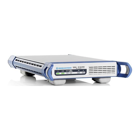
® Preface R&S SGS100A Documentation Overview Preface The R&S SGS is a signal generator intended either for the generation of IQ- modulated signals or as a pure local oscillator (LO) source. Optimized for use in automated test equipment (ATE), the instrument offers fast settling times in an exceptionally small form factor and low power consumption. -
Page 8: Getting Started Manual
® Preface R&S SGS100A Documentation Overview 1.2.1 Getting Started Manual Introduces the R&S SGS and describes how to set up and start working with the product. Includes basic operations, typical measurement examples, and general information, e.g. safety instructions, etc. A printed version is delivered with the instrument. -
Page 9: Basic Safety Instructions
1.2.8 Application Notes, Application Cards, White Papers, etc. These documents deal with special applications or background information on particular topics. See www.rohde-schwarz.com/application/sgs100a. Typographical Conventions The following text markers are used throughout this documentation: Getting Started 1416.0570.02 ─ 11... - Page 10 ® Preface R&S SGS100A Typographical Conventions Convention Description "Graphical user interface All names of graphical user interface elements on the screen, elements" such as dialog boxes, menus, options, buttons, and softkeys are enclosed by quotation marks. [Keys] Key and knob names are enclosed by square brackets.
-
Page 11: Preparing For Use
® Preparing for Use R&S SGS100A Putting into Operation Preparing for Use ● Putting into Operation..................9 ● Linux Operating System..................16 ● Connecting an External PC and Devices............16 Putting into Operation This section describes the basic steps to be taken when setting up the R&S SGS for the first time. -
Page 12: Emi Suppression
® Preparing for Use R&S SGS100A Putting into Operation Instrument damage caused by electrostatic discharge Electrostatic discharge (ESD) can damage the electronic components of the instrument and the device under test (DUT). Electrostatic discharge is most likely to occur when you connect or disconnect a DUT or test fixture to the instrument's test ports. -
Page 13: Unpacking And Checking The Instrument
® Preparing for Use R&S SGS100A Putting into Operation ● Note the EMC classification in the data sheet 2.1.2 Unpacking and Checking the Instrument Unpack the R&S SGS carefully and check the contents of the package. ● Check if all items listed on the delivery note, including this getting started manual, are included in the delivery. - Page 14 ® Preparing for Use R&S SGS100A Putting into Operation Bench top operation If the R&S SGS is operated on a bench top, the surface should be flat. The instru- ment can be used in horizontal position, standing on its feet.
-
Page 15: Switching The Instrument On And Off
® Preparing for Use R&S SGS100A Putting into Operation Risk of instrument damage due to insufficient airflow in a rack If you mount several instruments in a rack, you need an efficient ventilation concept to ensure that the instruments do not overheat. Insufficient airflow for a longer period can disturb the operation and even cause damage. - Page 16 ® Preparing for Use R&S SGS100A Putting into Operation In standby state, the button is orange. The standby power mode keeps the power switch circuits and the remote control system active. Start-up and booting The instrument boots the operating system and starts the instrument firmware.
-
Page 17: Function Check
® Preparing for Use R&S SGS100A Putting into Operation 2. To turn the power off, press the main power switch to position 0 (Off). None of the front-panel LEDs should be on. 2.1.6 Function Check The instrument automatically monitors the main functions when it is switched on and monitors them continuously during operation. -
Page 18: Linux Operating System
® Preparing for Use R&S SGS100A Connecting an External PC and Devices ● Preset the instrument to its factory settings The instrument can also be forced to load its default factory settings. To access the corresponding dialog box, select the "SGMA-GUI > Instrument Name >... -
Page 19: Installing The R&S Sgma-Gui Software
® Preparing for Use R&S SGS100A Connecting an External PC and Devices In addition to connecting an external controller, it may be useful to connect other external devices, e.g. a memory stick. The following interfaces are provided on the rear panel of the instrument, see also Chapter 3.2, "Rear Panel... - Page 20 ® Preparing for Use R&S SGS100A Connecting an External PC and Devices Table 2-1: Hardware and software requirements Requirement Remark R&S SGMA-GUI has to be installed on one of the supported One of the following operating operating systems. Also, the version of the operating system systems: must be still supported by Microsoft.
-
Page 21: Connecting A Remote Pc Via Lan
® Preparing for Use R&S SGS100A Connecting an External PC and Devices Start the version that is required for your application. Uninstalling an old software version An uninstallation of a previous version of the SW can be performed before the installation of the new one, but this is not mandatory. - Page 22 ® Preparing for Use R&S SGS100A Connecting an External PC and Devices Risk of network failure Consult your network administrator before performing the following tasks: ● Connecting the instrument to the network ● Configuring the network ● Changing IP addresses Errors can affect the entire network.
-
Page 23: Assigning The Ip Address
® Preparing for Use R&S SGS100A Connecting an External PC and Devices 8. Edit the instrument settings in the "Edit Instrument" dialog ("SGMA-GUI > Setup > Instruments > Instrument> Edit"). 2.3.2.2 Assigning the IP Address Depending on the network capacities, the TCP/IP address information for the instrument can be obtained in different ways. -
Page 24: Automatically Adding Instruments To The Sgma-Gui
® Preparing for Use R&S SGS100A Connecting an External PC and Devices 4. Enter the "Subnet mask", for example 255.255.255.0. 5. Enter the "Default Gateway", for example 192.168.0.1. Assigning a static IP address to your Windows-PC network card 1. Obtain the IP address and subnet mask for the R&S SGS and the IP address for the local default gateway from your network administrator. -
Page 25: Connecting A Controller Via Pci Express
® Preparing for Use R&S SGS100A Connecting an External PC and Devices 2. Start the SGMA-GUI on a computer connected to the same network. 3. Open the "Instruments" dialog and click "Scan". Note: This step is performed automatically on the first start and can also be omitted for instruments with a direct LAN connection to the computer. - Page 26 ® Preparing for Use R&S SGS100A Connecting an External PC and Devices Figure 2-1 illustrates schematically the required connector type to emphasize on the different connector shape. Figure 2-1: USB type Micro-B connectors An external PC with installed R&S SGMA-GUI is required for manual operation of the R&S SGS.
- Page 27 ® Preparing for Use R&S SGS100A Connecting an External PC and Devices Figure 2-2 illustrates schematically the required connector type to emphasize on the different connector shape. Figure 2-2: USB type Micro-A connectors If you connect an R&S SGS to an R&S SGU via a USB cable, perform the steps as described in chapter "Setups for Connecting an R&S SGS and an R&S SGU"...
-
Page 28: Instrument Tour
® Instrument Tour R&S SGS100A Front Panel Tour Instrument Tour The following topics help you get familiar with the instrument and perform the first steps: ● Front Panel Tour ● Rear Panel Tour This section explains the control elements and the connectors of the R&S SGS with the aid of the front and rear views. - Page 29 ® Instrument Tour R&S SGS100A Front Panel Tour In standby state, the button is orange. In this state, it is safe to switch off the AC power and disconnect the instrument from the power supply. A blinking green color indicates that a booting operation is in process.
-
Page 30: Rear Panel Tour
® Instrument Tour R&S SGS100A Rear Panel Tour Green LED indicates that a network cable is connected to the instrument and no error in the DHCP connection is detected. But it does not indicate that the remote control connection is established for all cases. For example, if the instrument is set to use a "Static"... - Page 31 ® Instrument Tour R&S SGS100A Rear Panel Tour [PCI Express Connector] The PCIe (Peripheral Component Interconnect Express) single lane interface allows remote control with optimized speed. For details, see Chapter 2.3.3, "Connecting a Controller via PCI Express", on page 23.
- Page 32 ® Instrument Tour R&S SGS100A Rear Panel Tour [RF OUT] Provides an RF 50 Ohm signal output. NOTICE! Maximum input levels. Do not overload the RF output. The maximum permissible back-feed is specified in the data sheet. [I , Q] SMA female type connectors that are inputs of the I/Q modulator, provided for feeding of external signal.
- Page 33 ® Instrument Tour R&S SGS100A Rear Panel Tour [TRIG] Multi-purpose connector. The [TRIG] connector is used mainly as an input con- nector for an external pulse modulator source. [AC supply and power switch] The AC supply and power switch allow you to connect the R&S SGS to the power supply and switch on the instrument.
-
Page 34: First Steps With The Instrument
First Steps with the Instrument This section provides examples on how to configure the R&S SGS to generate a continuous wave (CW) signal via the R&S SGMA-GUI and the R&S SGS100A Web-GUI. Configuring a CW Signal with the R&S SGMA- The R&S SGS in this example is a base unit equipped with the frequency option... - Page 35 ® First Steps with the Instrument R&S SGS100A Configuring a CW Signal with the R&S SGMA-GUI The [POWER ON/STANDBY] and [LAN] key have to be green. 2. On the connected remote PC, start the R&S SGMA-GUI software application. The main panel of the application opens. The panel provides a quick access to the main settings of the configured and activated instruments.
-
Page 36: Configuring A Cw Signal With The R&S Sgs100A Web-Gui
Configuring a CW Signal with the R&S SGS100A Web-GUI The R&S SGS100A Web-GUI is an alternative way to operate the R&S SGS. There is no installation needed. It can be used with all devices and operating sys- tems, including tablets and smart phones, which have one of the following web browsers installed: ●... - Page 37 To connect to the R&S SGS from an external device, both of them must have access to the same network, i.e. use a shared network. The feature set of the R&S SGS100A Web-GUI is limited to the most common settings, needed especially for modifying the output signal. For additional actions like firmware updates or adjustments, please use the R&S SGMA-GUI.
- Page 38 SGS100A Configuring a CW Signal with the R&S SGS100A Web-GUI In the R&S SGS100A Web-GUI main panel, the green indicator "System Sta- tus > OK " confirms that there is a connection between the instrument and the remote PC and that the instrument is recognized by the software.
-
Page 39: Instrument Control
® Instrument Control R&S SGS100A Manual Operation via R&S SGMA-GUI Instrument Control As a rule, the R&S SGS is operated exclusively via programmatic remote control from a connected PC. For service and diagnostic tasks, and for manual configura- tion, a graphical user interface (R&S SGMA-GUI) is provided which runs on the remote PC. -
Page 40: How To Use The Help System
® Instrument Control R&S SGS100A Manual Operation via R&S SGMA-GUI The main dialog comprises two main areas: ● On the top of the main panel, there are the menu bar, the tool bar and the info bar with the corresponding "Info" button. - Page 41 ® Instrument Control R&S SGS100A Manual Operation via R&S SGMA-GUI Contents of the help dialog box The help dialog box contains two main areas: ● "Contents" - contains a table of help contents ● "Topic" - contains a specific help topic The help system also provides an "Index", "Find"...
-
Page 42: Network And Remote Control Operation
® Instrument Control R&S SGS100A Network and Remote Control Operation 2. Enter the first characters of the topic you are interested in. The entries starting with these characters are displayed. 3. Press the [ENTER] key to display the help topic. -
Page 43: Lan Interface
® Instrument Control R&S SGS100A Network and Remote Control Operation Interface Protocols Remarks PCIe Proprietary A PCIe connector is located on the rear panel of the instrument. For details, see Chapter 5.2.1.3, "PCI Express Interface", on page 45 GPIB –... - Page 44 ® Instrument Control R&S SGS100A Network and Remote Control Operation VISA Resource Strings The VISA resource string is required to establish a communication session between the controller and the instrument in a LAN. The resource string is a unique identifier, composed of the specific IP address of the instrument and some network and VISA-specific keywords.
- Page 45 ® Instrument Control R&S SGS100A Network and Remote Control Operation For details of the VXI-11 protocol, refer to ."VXI-11 Protocol" on page 44 Socket communication TCPIP::host address::port::SOCKET ● port determines the used port number ● SOCKET indicates the raw network socket resource class Socket communication requires the specification of the port (commonly referred to as port number) and of "SOCKET"...
- Page 46 ® Instrument Control R&S SGS100A Network and Remote Control Operation ● Usable for IPv6 or IPv4 networks Using VXI-11, each operation is blocked until a VXI-11 device handshake returns. However, using HiSLIP, data is sent to the device using the "fire and forget"...
-
Page 47: Usb Interface
® Instrument Control R&S SGS100A Network and Remote Control Operation 5.2.1.2 USB Interface For remote control via USB connection, the PC and the instrument must be con- nected via the USB interface. A USB connection requires the VISA library to be installed. -
Page 48: Gpib Interface (Iec/Ieee Bus Interface)
® Instrument Control R&S SGS100A Network and Remote Control Operation Using the PCIe interface for remote control of the instrument requires extended knowledge and is described in section "Advanced Remote Con- trol via PCIe" in the user manual. 5.2.1.4 GPIB Interface (IEC/IEEE Bus Interface) The R&S SGS is not equipped with an IEC/IEEE bus interface. -
Page 49: Example: Remote Control Over Lan Using The Vxi-11 Protocol
® Instrument Control R&S SGS100A Network and Remote Control Operation 5.2.2 Example: Remote Control over LAN Using the VXI-11 Pro- tocol In the following example, the program "Measurement & Automation Explorer" from National Instruments is used on a Windows operating system to set up a LAN remote control link and to start a remote control session. - Page 50 ® Instrument Control R&S SGS100A Network and Remote Control Operation To enable the external controller to communicate with the software via TCP/IP protocol, set up a remote control link as follows: 1. Connect the controller and the instrument to the network (network cable).
- Page 51 ® Instrument Control R&S SGS100A Network and Remote Control Operation The alias name should not be mistaken for the computer name. It is only used for instrument identification within the program and displayed in the menu as an option if there is an Ethernet link.
- Page 52 ® Instrument Control R&S SGS100A Network and Remote Control Operation 2. In the "Configuration" window, select "Device and Interfaces > VISA TCP/IP Resources", select the required instrument and select "Open VISA Test Panel". 3. In the "viWrite" tab, write the command to be sent to the instrument and select "Execute".
-
Page 53: Index
® Index R&S SGS100A Index GPIB ............40 Characteristics ........46 AC supply .......... 13, 31 Application cards ........7 Application notes ........7 Hardware Requirements ........18 Help ............6 Brochures ..........7 HiSLIP ............. 40 Protocol ..........43 Resource string ........42 Connector I ............ - Page 54 ® Index R&S SGS100A Key ............27 VXI protocol ........44 Safety instructions ........7 SCPI ERROR / WARNING ......27 Version ..........41 REF EXT ..........27 SCPI disabled ..........18 Linux ............16 Service manual ..........6 Shutting down ..........14 Connector ........... 30 Socket .............
Need help?
Do you have a question about the SGS100A and is the answer not in the manual?
Questions and answers