Table of Contents
Advertisement
Advertisement
Table of Contents

Related Manuals for Danfoss iC2


Summary of Contents for Danfoss iC2
- Page 1 Application Guide iC2-Micro Frequency Converters drives.danfoss.com |...
-
Page 3: Table Of Contents
Application Guide | iC2-Micro Frequency Converters Contents Introduction and Safety Purpose of this Application Guide Additional Resources Version History Safety Symbols General Safety Considerations Qualified Personnel Application Software Overview iC2-Micro Application Software Overview Basic Functions 2.2.1 Basic Functions Overview 2.2.2 Reference Handling 2.2.3... - Page 4 Application Guide | iC2-Micro Frequency Converters 2.4.6 Automatic Motor Adaptation (AMA) 2.4.7 Automation Energy Optimization (AEO) Braking of Load 2.5.1 Braking of Load Overview 2.5.2 Resistor Braking 2.5.3 Overvoltage Control (OVC) 2.5.4 DC Brake 2.5.5 AC Brake 2.5.6 DC Hold 2.5.7...
- Page 5 Application Guide | iC2-Micro Frequency Converters 3.2.4.3 Menu Group Screen and Navigation 3.2.4.4 Restoring Default Settings 3.2.5 Control Panel 2.0 OP2 Buttons and Indicators 3.2.6 Control Panel 2.0 OP2 Basic Configurations 3.2.6.1 Overview 3.2.6.2 Understanding Readout Screens 3.2.6.3 Menu Screen and Navigation 3.2.6.4...
- Page 6 Application Guide | iC2-Micro Frequency Converters 5.5.3 Configuring Process Control Mode 5.5.4 Configuring Multi-Speed Control Mode 5.5.5 Configuring Wire Control Mode 5.5.6 Configuring Torque Control Mode Reference Handling 5.6.1 Local/Remote Reference 5.6.2 Reference Limits 5.6.3 Scaling of Preset References and Bus References 5.6.4...
- Page 7 Application Guide | iC2-Micro Frequency Converters 6.2.2 Function Codes Supported by Modbus RTU 6.2.3 Modbus Exception Codes Parameter Descriptions Reading the Parameter Table 7.1.1 Understanding Parameter Types 7.1.2 Understanding Data Types 7.1.3 Understanding Access Types Grid (Menu Index 1) 7.2.1 Grid Settings (Menu Index 1.2)
- Page 8 Application Guide | iC2-Micro Frequency Converters 7.6.1 Status (Menu Index 5.1) 7.6.2 Protection (Menu Index 5.2) 7.6.3 Operation Mode (Menu Index 5.4) 7.6.4 Control (Menu Index 5.5) 7.6.4.1 General Settings (Menu Index 5.5.1) 7.6.4.2 Digital/Bus (Menu Index 5.5.2) 7.6.4.3 Reference (Menu Index 5.5.3) 7.6.4.4...
- Page 9 Application Guide | iC2-Micro Frequency Converters I/O (Menu Index 9) 7.9.1 I/O (Menu Index 9.3) 7.9.1.1 I/O Status (Menu Index 9.3) 7.9.2 Digital Inputs/Outputs (Menu Index 9.4) 7.9.2.1 Digital Input Setting (Menu Index 9.4.1) 7.9.2.2 T15 as Digital Output (Menu Index 9.4.2) 7.9.2.3...
- Page 10 Application Guide | iC2-Micro Frequency Converters | Danfoss A/S © 2024.03 AB413939445838en-000301 / 130R1254...
-
Page 11: Introduction And Safety
Additional Resources Following are the additional resources available to further understand the features, safely install, and operate the iC2-Micro Frequency Converters. The operating guide, which provides information about the installation, commissioning, and maintenance of iC2-Micro Frequency Converters. -
Page 12: General Safety Considerations
Application Guide | iC2-Micro Frequency Converters ISO warning symbol for hot surfaces and burn hazard ISO warning symbol for high voltage and electrical shock ISO action symbol for referring to the instructions General Safety Considerations When installing or operating the AC drive, pay attention to the safety information given in the instructions. For more information about safety guidelines for installation and operation, refer to the drive's operating guide. -
Page 13: Qualified Personnel
Application Guide | iC2-Micro Frequency Converters Table 1: Discharge Time Enclosure size Minimum waiting time (minutes) MA01c–MA02c and MA01a–MA03a MA04a–MA05a CAUTION INTERNAL FAILURE HAZARD An internal failure in the drive can result in serious injury when the drive is not properly closed. -
Page 14: Application Software Overview
Software Tools Basic Functions Basic Functions Overview 2.2.1 The application software consists of a wide range of basic features which enables the drive to control any application using the iC2-Micro drive. Reference Handling 2.2.2 References from multiple sources, matching the needs to control the application, are freely definable. -
Page 15: Motor Phase Switch
Application Guide | iC2-Micro Frequency Converters Motor Phase Switch 2.2.7 If motor phase cables have been installed in an incorrect order during installation, the rotation direction can be changed. This eliminates the need to change the order of motor phases. -
Page 16: Io Control And Readouts
Application Guide | iC2-Micro Frequency Converters Process controller The process controller can control a process, for example, in a system where a constant pressure, flow, or temperature is needed. Feedback from the application is connected to the drive, providing the actual output value. The controller ensures that the output is matching the reference provided by controlling the motor speed. -
Page 17: Automatic Motor Adaptation (Ama)
Application Guide | iC2-Micro Frequency Converters Automatic Motor Adaptation (AMA) 2.4.6 Automatic Motor Adaptation (AMA) provides optimization of motor parameters for improved shaft performance. Based on motor nameplate data and measurements of the motor at standstill, key motor parameters are being recalculated and used to fine tune the motor control algorithm. -
Page 18: Drive Protection Features
Application Guide | iC2-Micro Frequency Converters The grid is monitored for phase imbalance and phase loss. If the imbalance exceeds internal limits, a warning is provided and the user can initiate proper actions. In case of an under- or overvoltage on the grid, the drive will provide a warning and stop operation if the situation remains or exceeds critical limits. -
Page 19: Event Log And Operational Counters
Software Tools Overview 2.8.1 Danfoss offers a suite of desktop software tools which have been designed to provide easy operation and the highest level of customization of AC drives. APIs and the Danfoss Device Interface enable integration of the tools into proprietary systems and business processes. The MyDrive®... -
Page 20: User Interfaces And How To Configure
User Interfaces and How to Configure Overview of User Interfaces To interact with the iC2-Micro drive, use either control panel as the direct interface or MyDrive® Insight which is a PC tool for more advanced interaction with the drive. The iC2-Micro drive has a control panel with a display, control buttons, and status indicators. Using MyDrive® Insight provides the ability to access the drive remotely. -
Page 21: Control Panel Buttons And Indicators
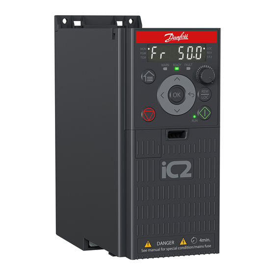
Application Guide | iC2-Micro Frequency Converters Control Panel Buttons and Indicators 3.2.3 WARN READY FAULT Figure 1: Control Panel Status indicators Operating indicators Home/Menu Left Stop/Reset Down Run indicator Start Back Remote/Local Potentiometer Status indicators Main display Table 2: Operation Buttons and Potentiometer... - Page 22 Application Guide | iC2-Micro Frequency Converters Table 2: Operation Buttons and Potentiometer (continued) Name Function Stop/Reset Stops the drive in local mode. Resets the drive to clear a fault. Potentiometer Changes the reference value when the reference value is selected as potentiometer.
-
Page 23: Control Panel Basic Configuration
Application Guide | iC2-Micro Frequency Converters Control Panel Basic Configuration 3.2.4 Overview of Control Panel Basic Configuration 3.2.4.1 Basic configurations of the control panel include: Readout status of the motor and the drive which includes warnings and faults. Navigate to the menus to view or change parameter settings for the drive. -
Page 24: Menu Group Screen And Navigation
All Parameters: To view all the parameters in the iC2-Micro Frequency Converters. Events Information: To view all active and history events such as faults, in the iC2-Micro Frequency Converters. Press the Up/Down button of the control panel to select the menu functions, as shown in the figure below. - Page 25 Quick Access Navigation 3.2.4.3.2 Quick Access consists of the following 3 functions to set up the iC2-Micro Frequency Converters easily in a step-by-step prescribed manner. q1 - Motor Data Setting: Enables to first select motor type, followed by motor data entry based on motor nameplate.
- Page 26 Application Guide | iC2-Micro Frequency Converters P4.2.1.1 Motor Type q1: Motor Data PM Motor *[0] IM Motor [1] SPM or [3] IPM P4.2.2.1 Nominal Power P4.2.2.3 Nominal Current P4.2.2.2 Nominal Voltage P4.2.2.5 Nominal Speed P4.2.2.3 Nominal Current P4.2.3.7 Motor Cont. Rated P4.2.2.4 Nominal Frequency...
- Page 27 Application Guide | iC2-Micro Frequency Converters Changing Selections in a Parameter In this example, the P 5.5.4.1 Ramp 1 Type Selector is considered. Figure 7 shows an overview of the relevant screens when changing the selections in a parameter. Figure 7: Changing Selections in a Parameter Press the Up/Down buttons to go to the parameter.
-
Page 28: Restoring Default Settings
Application Guide | iC2-Micro Frequency Converters Restoring Default Settings 3.2.4.4 Overview 3.2.4.4.1 Restoring the default parameter settings is done by initialization of the drive. Initialization is carried out via P 6.6.8 Operation Mode (recommended) or manually. Recommended initialization via P 6.6.8 Operation Mode does not reset the following settings: Operating hours. -
Page 29: Control Panel 2.0 Op2 Buttons And Indicators
Application Guide | iC2-Micro Frequency Converters Control Panel 2.0 OP2 Buttons and Indicators 3.2.5 Figure 9: Control Panel 2.0 OP2 Overview Table 7: Control Panel Elements Description Legend Name of element Description Display Provides access to content and settings. The display provides detailed information about the sta- tus of the drive. -
Page 30: Control Panel 2.0 Op2 Basic Configurations
Application Guide | iC2-Micro Frequency Converters Table 7: Control Panel Elements Description (continued) Legend Name of element Description RUN LED The indicator has the following states: • On: The drive is in normal operation. • Off: The drive has stopped. -
Page 31: Menu Screen And Navigation
Application Guide | iC2-Micro Frequency Converters Table 8: Legend Table Legend Description • The front number indicates active setup. • The number in brackets indicates the programming setup. • On Readout Screens, the value with unit after the setpoint icon is the reference setting data. -
Page 32: Parameter Group Screens And Overall Navigation
Application Guide | iC2-Micro Frequency Converters Table 9: Menu Screen Menu Function Quick Access Quick access for setting up a drive quickly. See 3.2.4.3.2 Quick Access Navigation. All Parameters View and set the parameters. Events Event list (including fault and warning that has occurred in the drive). -
Page 33: Changing Parameter Value
Application Guide | iC2-Micro Frequency Converters 1(1) 0.0 Hz Ramp 5.5.4.1 Ramp 1 Type Selec 5.5.4.2 Ramp 1 Accel. Time Figure 14: Changing Selections in a Parameter 1. To view the selections of the parameter, press OK. The selections available for the parameter is shown. A tick icon in the front of the selection indicates the selected choice. -
Page 34: Mydrive® Insight
MyDrive® Insight Overview of MyDrive® Insight 3.3.1 MyDrive® Insight is a platform-independent software tool that supports the commissioning, engineering, and monitoring of iC2-Micro Frequency Converters. Some of the key features include: Fast and easy configuration and commissioning. Monitor the drives as part of daily operations. -
Page 35: Getting Started With Mydrive® Insight
Application Guide | iC2-Micro Frequency Converters Getting Started with MyDrive® Insight 3.3.2 As a prerequisite, ensure that MyDrive® Insight is installed on the device (PC or laptop). Download and install MyDrive® Insight from MyDrive® Suite available at https://suite.mydrive.danfoss.com/. To establish a point-to-point connection between the drive and the device, use either of the following 2 methods: –... -
Page 36: Accessing Parameters And Understanding Parameter Screens In Mydrive® Insight
Application Guide | iC2-Micro Frequency Converters Figure 20: Serial Connection Once the connection is established, the Device Info view is shown. Accessing Parameters and Understanding Parameter Screens in MyDrive® Insight 3.3.3 Accessing parameters 1. To access the parameters of the connected drive, click Setup & Service. This opens the menus related to Setup & Service. - Page 37 Application Guide | iC2-Micro Frequency Converters Figure 21: Setup & Service Parameter screen overview Following is an overview of the Parameter (Live) screen in MyDrive® Insight, which describes the Parameter screen. Figure 22: Parameter Screen Danfoss A/S © 2024.03 AB413939445838en-000301 / 130R1254 |...
- Page 38 Application Guide | iC2-Micro Frequency Converters Table 11: Legend Table Legend Name Description Parameter group Navigate through the different parameter groups in the drive. Search button To find a specific parameter. Value field View and change a parameter value or selection. On the Live screen, all the parameters for the drive are shown in MyDrive®...
-
Page 39: Viewing And Changing Parameter Settings
Application Guide | iC2-Micro Frequency Converters Figure 24: Search Button Viewing and Changing Parameter Settings 3.3.4 When in a specific parameter group, all parameters related to the parameter group are shown. Depending on the access type of the parameter, there is a possibility to view the parameter setting or change the current selection or value of the parameter. -
Page 40: Pc Control To Operate The Drive Using Mydrive® Insight
Application Guide | iC2-Micro Frequency Converters Table 12: Legend Table (continued) Number Field Name Description To see all selections available for the parameter, click the value in the Value field. Selection para- meters Default The factory setting (default value) of the parameter. -
Page 41: Backing Up The Drive
Application Guide | iC2-Micro Frequency Converters Figure 26: Operate Drive using MyDrive® Insight To access PC Control in MyDrive® Insight and operate the drive, perform the following: Click the REQUEST CONTROL button. Click Continue, to confirm secure operation conditions, while controlling the drive using MyDrive® Insight. - Page 42 Application Guide | iC2-Micro Frequency Converters Figure 27: Backup Destination Icon This opens a screen to select the backup destination. The destinations for backup are: Project: Backup an existing project or a new project. ¢ Figure 28: Backup Destination Click Next.
-
Page 43: Restoring The Data To The Drive
Application Guide | iC2-Micro Frequency Converters Figure 29: Backup File in the Menu Restoring the Data to the Drive 3.3.7 To restore data to the drive, select a drive, go to Setup & Service→Parameters. Click the icon as shown in the image below. - Page 44 Application Guide | iC2-Micro Frequency Converters Figure 31: Source of Data for Restore Click Next, and select a backup source drive. Click Next and select a backup. Select the content for restoring data into the drive, and click Next. ...
-
Page 45: Application Software Structure And Overview
Application Guide | iC2-Micro Frequency Converters Application Software Structure and Overview Understanding Application Software Structure The basic design principle of the application software structure and the related hierarchy refers to the setup of a typical iC2-Micro drive, as shown in the Figure 6 Maintenance &... - Page 46 Application Guide | iC2-Micro Frequency Converters Menu index/Parameter group Parameter group name Description Application Contains parameters for application specific features such as process control, speed control, torque control, mechanical brake control, and many more. Maintenance & Service Contains parameters exclusively related to status, events, and service features.
- Page 47 Application Guide | iC2-Micro Frequency Converters Figure 34: Parameter Groups Danfoss A/S © 2024.03 AB413939445838en-000301 / 130R1254 |...
-
Page 48: Configuration Setup Examples
3.2.4.1 Overview of Control Panel Basic Configuration. For information on using MyDrive® Insight, see 3.3.1 Overview of MyDrive® Insight. Detailed information about the parameters is described in Chapter Parameter Descriptions. A typical wiring schematic for iC2-Micro Frequency Converters is shown. L1/L Power L3/N input Motor... -
Page 49: Basic Setup Of A Drive
Basic Setup of a Drive The procedure covers the basic set-up of a drive. Prerequisite: Ensure that the drive is mounted safely as described in the iC2-Micro Frequency Converters Operating Guide. To use MyDrive® Insight for configuration, install MyDrive® Insight from MyDrive Suite app. -
Page 50: Setting Up The Drive Using Quick Access Via Control Panel
Application Guide | iC2-Micro Frequency Converters Parameter index Parameter name Example setting Parameter number 5.5.3.9 Reference 3 Source [11] Local Bus Reference 5.5.2.1 Coasting Select [3] Logic OR 5.5.2.2 Quick Stop Select [3] Logic OR 5.5.2.4 Start Select [3] Logic OR 5.5.2.5... -
Page 51: Pm Motor Setup In Vvc
Application Guide | iC2-Micro Frequency Converters Parameter index Parameter name Recommended setting Parameter number 4.2.2.1 Nominal Power As shown on nameplate. 4.2.2.2 Nominal Voltage As shown on nameplate. 4.2.2.4 Nominal Frequency As shown on nameplate. 4.2.2.3 Nominal Current As shown on nameplate. - Page 52 Application Guide | iC2-Micro Frequency Converters Parameter index Parameter name Recommended setting Parameter number 4.2.3.1 Stator Resistance (Rs) Enter line-to-common stator winding resistance (Rs). If only line-to-line data is available, divide the line-to-line value by 2 to achieve the line-to- common (starpoint) value.
-
Page 53: Speed Control Configuration With I/O Using Default
Application Guide | iC2-Micro Frequency Converters To test motor operation, start the motor at low speed (100–200 RPM). If the motor does not turn, check installation, general parameter configurations, and motor data. Perform parking operation by setting P 5.6.14 Sync. Motor Parking Current % and P 5.6.13 Sync. Motor Parking Time. The factory setting values of the parameters can be adjusted and increased for applications with high inertia. -
Page 54: Automatic Motor Adaptation (Ama)
Application Guide | iC2-Micro Frequency Converters Parameter index Parameter name Recommended settings Parameter number 5.5.3.4 Reference Minimum Use default: 0 5.5.4.2 Ramp 1 Accel. Time Set value according to real application. 5.5.4.3 Ramp 1. Decel. Time Set value according to real application. -
Page 55: Configuring Speed Control Mode
Application Guide | iC2-Micro Frequency Converters The iC2-Micro Frequency Converters have 5 standard modes which have pre-configured parameters and are set automatically. Table 14 contains a summary of the different modes and suitable applications. Table 14: Standard Modes and Suitable Application... - Page 56 Application Guide | iC2-Micro Frequency Converters Start (1) / Stop (0) Reverse (1) / Forward (0) Reset Output Frequency 1k Ohm Speed Reference 1 Fault RELAY Figure 37: Default Connections Set P 5.4.1 Application Selection to [20] Speed Control Mode.
-
Page 57: Configuring Process Control Mode
Application Guide | iC2-Micro Frequency Converters Table 15: Default Settings (continued) Category Parameter index Parameter name Default setting Parameter number AI1 - T33 9.5.2.1 T33 mode [1] Voltage Mode 9.5.2.2 T33 High Voltage 9.5.2.3 T33 Low Voltage 0.07V 9.5.2.6 T33 High Ref./Feedb. - Page 58 Application Guide | iC2-Micro Frequency Converters Start (1) / Stop (0) Reset Jog (Speed Mode) Output Frequency 1k Ohm Process Reference 1 Process Feedback Fault RELAY Figure 38: Default Connections for Process Control Set P 5.4.1 Application Selection to [21] Process Control Mode.
-
Page 59: Configuring Multi-Speed Control Mode
Application Guide | iC2-Micro Frequency Converters Table 16: Process Control Mode Default Settings (continued) Category Parameter index Parameter name Default setting Parameter number AI1 - T33 9.5.2.1 T33 mode [1] Voltage Mode 9.5.2.2 T33 High Voltage 9.5.2.3 T33 Low Voltage 0.07 V... - Page 60 Application Guide | iC2-Micro Frequency Converters Start (1) / Stop (0) Reverse (1) / Forward (0) Reset Preset Ref. bit 0 Preset Ref. bit 1 Output Frequency Fault RELAY Figure 39: Default Connections Set P 5.4.1 Application Selection to [22] Multi-speed Control Mode.
-
Page 61: Configuring Wire Control Mode
Application Guide | iC2-Micro Frequency Converters Table 17: Default Settings (continued) Category Parameter index Parameter name Default setting Parameter number External reference 5.5.3.7 Reference 1 Source [0] No Function 5.5.3.8 Reference 2 Source [0] No Function 5.5.3.9 Reference 3 Source... - Page 62 Application Guide | iC2-Micro Frequency Converters Start (pulse Reverse (1) / Forward (0) Reset Stop (pulse Output Frequency 1k Ohm Speed Reference 1 Fault RELAY Figure 40: Default Connections Set P 5.4.1 Application Selection to [23] 3-Wire Control Mode. When [23] 3-Wire Control Mode is selected, the following parameters are automatically set to the values shown in the table.
- Page 63 Application Guide | iC2-Micro Frequency Converters Table 19: Default Settings (continued) Category Parameter index Parameter name Default setting Parameter number AI1 - T33 9.5.2.1 T33 Mode [1] Voltage Mode 9.5.2.2 T33 High Voltage 10 V 9.5.2.3 T33 Low Voltage 0.07 V 9.5.2.6...
-
Page 64: Configuring Torque Control Mode
Application Guide | iC2-Micro Frequency Converters Configuring Torque Control Mode 5.5.6 In torque control mode, the pre-configured parameter settings require to control the motor via torque. The motor torque follows a torque reference given by an analog input to the frequency converter. Analog input 1 is used as torque reference; analog input 2 is used as maximum speed limitation source for torque control. - Page 65 Application Guide | iC2-Micro Frequency Converters Table 20: Default Settings Category Parameter index Parameter name Default setting Parameter number Operation mode 5.4.2 Operation Mode [4] Torque Open Loop DI 1 - T13 9.4.1.2 T13 Digital Input [8] Start DI 2 - T14 9.4.1.3...
-
Page 66: Reference Handling
Application Guide | iC2-Micro Frequency Converters Table 20: Default Settings (continued) Category Parameter index Parameter name Default setting Parameter number 5.9.2 Jog Reference 5.0 Hz 5.9.1 Jog Ramp Time Reference limits 5.5.3.3 Reference Maximum Value is automatically calculated according to motor data. - Page 67 Application Guide | iC2-Micro Frequency Converters No function Analog ref. Pulse ref. Local bus ref. Control Panel Potentiometer P 5.5.3.11 Preset relative ref. P 5.5.3.1 P 5.4.2 Ref./feedback range Configuration mode P 9.4.2.1x(19)/P 9.4.2.1x(20) Speed open loop Freeze ref. Scale to -max ref./...
-
Page 68: Reference Limits
Application Guide | iC2-Micro Frequency Converters The 2 types of reference inputs are combined in the following formula: Remote reference=X+X*Y/100% If relative reference is not used, set P 5.5.3.12 Relative Scaling Reference Resource to [0] No function and P 5.5.3.11 Preset Relative Reference to 0%. -
Page 69: Scaling Of Preset References And Bus References
Application Guide | iC2-Micro Frequency Converters Reference range = Minimum to maximum Resulting reference Maximum reference Sum of all Minimum reference references Figure 46: Sum of all References when Configuration Mode is set to Process Scaling of Preset References and Bus References 5.6.3... -
Page 70: Dead Band Around Zero
Application Guide | iC2-Micro Frequency Converters The endpoints P1 and P2 are defined in the Table 21 depending on the choice of input. Table 21: P1 and P2 Endpoints Input AI 33 voltage mode AI 34 voltage mode AI 34 current mode... - Page 71 Application Guide | iC2-Micro Frequency Converters General Reference General Motor parameters: parameters: Limited to: -200%- +200% Reference Range: Min - Max Motor speed direction:Both directions (-40 Hz- +40 Hz) Minimum Reference: 0 Hz (0,0%) Motor speed Low limit: 0 Hz...
- Page 72 Application Guide | iC2-Micro Frequency Converters General Reference General Motor parameters: parameters: Limited to: -200%- +200% Reference Range: -Max - Max Motor speed direction: Both directions (-40 Hz- +40 Hz) Minimum Reference: Don't care Motor speed Low limit: 0 Hz Maximum Reference: 20 Hz (100.0%)
-
Page 73: Rs485 Configurations
Application Guide | iC2-Micro Frequency Converters RS485 Configurations RS485 Installation and Set up Introduction 6.1.1 RS485 is a 2-wire bus interface compatible with multi-drop network topology. The nodes can be connected as a bus, or via drop cables from a common trunk line. A total of 32 nodes can be connected to 1 network segment. Repeaters divide network segments, see the... -
Page 74: Connecting The Drive To The Rs485 Network
Application Guide | iC2-Micro Frequency Converters Table 22: Cable Specifications Cable Shielded twisted pair (STP) Impedance [Ω] Cable length [m (ft)] Maximum 1200 (3937) (including drop lines). Maximum 500 (1640) station-to-station. Connecting the Drive to the RS485 Network 6.1.2 Connect signal wires to terminal 68 (P+) and terminal 69 (N-) on the main control board of the drive. -
Page 75: Emc Precautions
Specify a maximum delay time between sending a request and receiving a response. EMC Precautions 6.1.5 To achieve interference-free operation of the RS485 network, Danfoss recommends the following EMC precautions. NOTICE Observe relevant national and local regulations, for example regarding protective earth connection. Failure to ground the cables properly can result in communication degradation and equipment damage. -
Page 76: Fc Protocol
FC Protocol Overview 6.1.6.1 The FC protocol, also referred to as FC bus or standard bus, is the Danfoss standard fieldbus. It defines an access technique according to the master/follower principle for communications via a fieldbus. One master and a maximum of 126 followers can be connected to the bus. The master selects the individual followers via an address character in the telegram. -
Page 77: Fc Protocol Message Framing Structure
Application Guide | iC2-Micro Frequency Converters Reset after a fault trip. Run at various preset speeds. Run in reverse. Change of the active set-up. Control of the 2 relays built into the drive. The bus reference is commonly used for speed control. It is also possible to access the parameters, read their values, and where possible, write values to them. - Page 78 Application Guide | iC2-Micro Frequency Converters Drive Address (ADR) 6.1.6.2.4 Address format 1–126: Bit 7 = 1 (address format 1–126 active). Bit 0–6 = drive address 1–126. Bit 0–6 = 0 broadcast. The follower returns the address byte unchanged to the master in the response telegram.
- Page 79 Application Guide | iC2-Micro Frequency Converters The PKE Field 6.1.6.2.7 The PKE field contains 2 subfields: Parameter command and response (AK) Parameter number (PNU) high 15 14 13 12 11 10 9 8 7 6 5 4 3 2 1 0 Figure 60: PKE Field Bits 12–15 transfer parameter commands from master to follower and return processed follower responses to the master.
- Page 80 Application Guide | iC2-Micro Frequency Converters Table 26: Response (continued) Command cannot be performed. Text transferred. If the command cannot be performed, the follower sends 0111 Command cannot be performed response and issues the following fault reports in the Table...
- Page 81 Application Guide | iC2-Micro Frequency Converters Index (IND) 6.1.6.2.9 The index is used with the parameter number to read/write access parameters with an index, for example, P 6.1.1 Latest Fault Number. The index consists of 2 bytes: a low byte and a high byte. Only the low byte is used as an index.
-
Page 82: Examples
Application Guide | iC2-Micro Frequency Converters Table 29: Conversion Conversion index Conversion factor 3600 0.01 0.001 0.0001 0.00001 Process Words (PCD) 6.1.6.2.13 The block of process words is divided into 2 blocks of 16 bits, which always occur in the defined sequence. -
Page 83: Modbus Rtu
Application Guide | iC2-Micro Frequency Converters E19E 0000 0000 03E8 PWE high Figure 61: Telegram NOTICE P 5.8.2 Motor Speed High Limit [Hz] is a single word, and the parameter command for write in EEPROM is E. P 5.8.2 Motor Speed High Limit [Hz] is 19E in hexadecimal. -
Page 84: Drive With Modbus Rtu
Application Guide | iC2-Micro Frequency Converters Danfoss assumes that the installed controller supports the interfaces in this manual, and strictly observes all requirements and limitations stipulated in the controller and drive. The built-in Modbus RTU (remote terminal unit) is designed to communicate with any controller that supports the interfaces defined in this guide. -
Page 85: Network Configuration
Application Guide | iC2-Micro Frequency Converters The bus reference is commonly used for speed control. It is also possible to access the parameters, read their values, and, where possible, write values to them. Accessing the parameters offers a range of control options, including controlling the setpoint of the drive when its internal PI controller is used. - Page 86 Application Guide | iC2-Micro Frequency Converters Table 34: Typical Modbus RTU Telegram Structure Start Address Function Data CRC check T1-T2-T3- T4 8 bits 8 bits N x 8 bits 16 bits T1-T2-T3- T4 Start/Stop Field 6.1.7.4.3 Telegrams start with a silent period of at least 3.5 character intervals. The silent period is implemented as a multiple of character intervals at the selected network baud rate (shown as Start T1-T2-T3-T4).
- Page 87 Application Guide | iC2-Micro Frequency Converters CRC Check Field 6.1.7.4.7 Telegrams include an error-checking field, operating based on a cyclic redundancy check (CRC) method. The CRC field checks the contents of the entire telegram. It is applied regardless of any parity check method used for the individual characters of the telegram.
- Page 88 Application Guide | iC2-Micro Frequency Converters Table 36: Drive Control Word (FC Profile) (continued) Coil Coast stop No coast stop Quick stop No quick stop Freeze frequency No freeze frequency Ramp stop Start No reset Reset No jog Ramp 1...
-
Page 89: How To Access Parameters
Application Guide | iC2-Micro Frequency Converters Table 37: Drive Status Word (FC Profile) (continued) Coil Not in current limit Current limit No thermal warning Thermal warning Address/Registers Table 38: Address/Registers Bus address PLC register Content Access Description Bus register 40001 Reserved –... -
Page 90: Examples
Application Guide | iC2-Micro Frequency Converters Examples Reading P 5.5.3.13 Freeze Up/Down Step Delta (16 bit): The parameter numbers is 312, and the register address is 3119 holding the parameters value. A value of 1252 (decimal), means that the parameter is set to 12.52%. - Page 91 Application Guide | iC2-Micro Frequency Converters Table 39: Query Field name Example (hex) Follower address 01 (drive address) Function 01 (read coils) Starting address HI Starting address LO 20 (32 decimals) coil 33 Number of points HI Number of points LO...
- Page 92 Application Guide | iC2-Micro Frequency Converters Table 41: Query Field name Example (hex) Follower address Function 03 (Read holding registers) Starting address HI 0B (Register address 3029) Starting address LO D5 (Register address 3029) Number of points HI 02 – (P 5.5.3.3 Reference Maximum is 32 bits long, that is, 2 regis-...
- Page 93 Application Guide | iC2-Micro Frequency Converters Table 43: Query Field name Example (hex) Follower address 01 (drive address) Function 05 (write single coil) Coil address HI Coil address LO 40 (64 decimal) Coil 65 Force data HI Force data LO...
- Page 94 Application Guide | iC2-Micro Frequency Converters Table 45: Query (continued) Field name Example (hex) Starting address LO E7 (register address 999) Preset data HI Preset data LO Error check (CRC) – Response The normal response is an echo of the query, returned after the register contents have been passed.
- Page 95 Application Guide | iC2-Micro Frequency Converters Table 47: Query (continued) Field name Example (hex) Write data HI (Register 4: 1049) Write data LO (Register 4: 1049) Write data HI (Register 4: 1050) Write data LO (Register 4: 1050) Error check (CRC) –...
-
Page 96: Danfoss Fc Control Profile
Application Guide | iC2-Micro Frequency Converters Table 49: Query (continued) Field name Example (hex) Quantity of coils HI Quantity of coils LO 10 (16 coils) Byte count Force data HI (Coils 8–1) Force data LO (Coils 16–9) 00 (reference = 2000 hex) Error check (CRC) –... -
Page 97: Explanation Of Control Word Bit
Application Guide | iC2-Micro Frequency Converters Table 52: Lower Register Numbers for Input and Output Data (continued) 02910 output data Frequency converter status word register (STW) 02911 output data Frequency converter main value register (MAV) Master-follower Speed ref. no.: 15 14 13 12 11 10 9 8 7 6 5 4 3 2 1 0... - Page 98 Application Guide | iC2-Micro Frequency Converters Table 54: Control Bits Programmed reference value Parameter Bit 01 Bit 00 P 5.5.3.10 Preset Reference [0] P 5.5.3.10 Preset Reference [1] P 5.5.3.10 Preset Reference [2] P 5.5.3.10 Preset Reference [3] NOTICE In P 5.5.2.7 Preset Reference Select, define how bit 00/01 gates with the corresponding function on the digital inputs.
-
Page 99: Status Word According To Fc Profile (Stw)
Application Guide | iC2-Micro Frequency Converters Bit 08, Jog Bit 08=1: P 5.9.2 Jog Speed [Hz] determines the output frequency. Bit 09, Selection of Ramp 1/2 Bit 09=0: Ramp 1 is active (P 5.5.4.2 Ramp 1 Ramp Up Time to P 5.5.4.3 Ramp 1 Ramp Down Time). -
Page 100: Explanation Of Status Word Bit
Application Guide | iC2-Micro Frequency Converters Follower-master Output freq. no.: 15 14 13 12 11 10 9 8 7 6 5 4 3 2 1 0 Figure 66: Status Word Table 56: Status Word According to FC Profile Bit = 0... - Page 101 Application Guide | iC2-Micro Frequency Converters Bit 02=1: The drive starts the motor with a start command. Bit 03, No Error/Trip Bit 03=0: The drive is not in fault mode. Bit 03=1: The drive trips. To re-establish operation, press [Reset].
-
Page 102: Bus Speed Reference Value
Application Guide | iC2-Micro Frequency Converters Bit 13=0: There are no voltage warnings. Bit 13=1: The DC voltage in the drive’s DC link is too low or too high. Bit 14, Torque OK/Limit Exceeded Bit 14=0: The motor current is lower than the current limit selected in P 2.7.1 Output Current Limit %. -
Page 103: How To Control The Drive
Application Guide | iC2-Micro Frequency Converters How to Control the Drive Introduction 6.2.1 This section describes codes which can be used in the function and data fields of a Modbus RTU telegram. Function Codes Supported by Modbus RTU 6.2.2 Modbus RTU supports use of the following function codes in the function field of a telegram:... - Page 104 Application Guide | iC2-Micro Frequency Converters Table 59: Modbus Exception Codes Code Name Meaning Illegal function The function code received in the query is not an allowable action for the server (or follower). This may be because the function code is only applicable to newer devices and was not implemented in the unit selected.
-
Page 105: Parameter Descriptions
The value of the parameter is within the specified range. In the example specified, the user can set any value 0– 255, for the parameter. Understanding Data Types 7.1.2 Following is an overview of the data types used in iC2 application software. Table 61: Overview on data type Data type Description... -
Page 106: Understanding Access Types
Application Guide | iC2-Micro Frequency Converters Table 61: Overview on data type (continued) Data type Description Type Range uint Unsigned integer 8, 16, 32 0 up to 65535 visStr Visible string All strings Understanding Access Types 7.1.3 Following are the access type of parameters and descriptions. -
Page 107: Grid Protection (Menu Index 1.3)
Application Guide | iC2-Micro Frequency Converters Selection number Selection name 200-240V/50Hz/IT-grid 200-240V/50Hz/Delta 200-240V/50Hz 100-110V/50Hz/IT-grid 100-110V/50Hz/Delta 100-110V/50Hz 380-440V/50Hz/IT-grid 380-440V/50Hz/Delta 380-440V/50Hz 440-480V/50Hz/IT-grid 440-480V/50Hz/Delta 440-480V/50Hz 200-240V/60Hz/IT-grid 200-240V/60Hz/Delta 200-240V/60Hz 100-110V/60Hz/IT-grid 100-110V/60Hz/Delta 100-110V/60Hz 380-440V/60Hz/IT-grid 380-440V/60Hz/Delta 380-440V/60Hz 440-480V/60Hz/IT-grid 440-480V/60Hz/Delta 440-480V/60Hz Grid Protection (Menu Index 1.3) 7.2.2 P 1.3.1 Mains Imbalance Action... -
Page 108: Power Conversion & Dc-Link (Menu Index 2)
Application Guide | iC2-Micro Frequency Converters Parameter Unit: 1412 – number: Data type: Access type: enum Read/Write The following are the selections for the parameter. Selection number Selection name Selection description Trip Trips the frequency converter. Warning Issue a warning. -
Page 109: Protection (Menu Index 2.3)
Application Guide | iC2-Micro Frequency Converters Parameter Unit: 1636 number: Data type: Access type: uint16 Read P 2.1.5 Output Current Limit % View the inverter maximum current, which should match the nameplate data on the connected motor. The data is used for calculation of torque and motor protection. - Page 110 Application Guide | iC2-Micro Frequency Converters Selection number Selection name Selection description Disabled No OVC required. Enabled (not at stop) Activate OVC except when using a stop signal to stop the frequency converter. Enable Activate OVC. CAUTION PERSONAL INJURY AND EQUIPMENT DAMAGE Enabling OVC in hoisting applications may lead to personal injuries and equipment damage.
- Page 111 Application Guide | iC2-Micro Frequency Converters Selection number Selection name Selection description No Function The frequency converter does not compensate for a mains interruption. The voltage on the DC link drops quickly, and the motor is lost within milliseconds to seconds. Trip lock is the result.
- Page 112 Application Guide | iC2-Micro Frequency Converters Selection number Selection name Selection description Kinetic Back-up Kinetic back-up ensures that the frequency converter keeps running as long as there is energy in the system due to the inertia from motor and load. This is done by converting the mechanical energy to the DC link and thereby maintaining control of the frequency converter and motor.
- Page 113 Application Guide | iC2-Micro Frequency Converters Selection number Selection name Selection description Fault Kin. Back-up, Trip with Recovery Kinetic backup with recovery combines the features of kinetic backup and kinetic backup with trip. This feature makes it possible to select between kinetic backup and kinetic backup with trip based on a recovery speed, which is configurable in P 2.3.8 Kin.
- Page 114 Application Guide | iC2-Micro Frequency Converters Data type: Access type: uint16 Read/Write P 2.3.10 Fast Mains Phase Loss Min. Power Fast detection is not activated if the actual power is lower than the value specified in the parameter. Default value: Parameter type: Range (0–100)
-
Page 115: Modulation (Menu Index 2.4)
Application Guide | iC2-Micro Frequency Converters Parameter Unit: 1427 number: Data type: Access type: enum Read/Write The following are the selections for the parameter. Selection number Selection name Selection description Trip Disable the protection filters and trip at the 1st fault. - Page 116 Application Guide | iC2-Micro Frequency Converters Data type: Access type: enum Read/Write Selection number Selection name 2.0 KHz 3.0 KHz 4.0 KHz 5.0 KHz 6.0 KHz 8.0 KHz 10.0 KHz 12.0 KHz 16.0 KHz P 2.4.3 Switching Frequency Adjust the switching frequency to find a suitable balance between the acoustic noise from the motor and thermal losses in the frequency converter.
-
Page 117: Dc-Link Control (Menu Index 2.5)
Application Guide | iC2-Micro Frequency Converters P 2.4.5 Over Modulation Use the parameter to enable or disable overmodulation of the output voltage. Select [1] On to obtain extra DC-link voltage and torque on the motor shaft. Select [0] Off to avoid torque ripple on the motor shaft. -
Page 118: Output Current Limit (Menu Index 2.7)
Application Guide | iC2-Micro Frequency Converters Selection number Selection name Output Current Limit (Menu Index 2.7) 7.3.5 P 2.7.1 Output Current Limit % Enter the current limit for motor and generator operation. The parameter is changed automatically if P 4.2.2.3 Nominal Motor Current is updated. -
Page 119: Filters & Brake Chopper (Menu Index 3)
Application Guide | iC2-Micro Frequency Converters Data type: Access type: uint16 Read/Write P 2.7.5 Trip Delay at Current Limit When the output current reaches the current limit (P 2.7.1 Output Current Limit %), a warning is triggered. If the current limit warning is continuously present for the period specified in this parameter, the frequency converter trips. -
Page 120: Brake Resistor (Menu Index 3.3)
Application Guide | iC2-Micro Frequency Converters Parameter Unit: number: Data type: Access type: uint16 Read/Write Brake Resistor (Menu Index 3.3) 7.4.3 P 3.3.2 Brake Resistor Value Set the brake resistor value in Ω. This value is used for monitoring the power to the brake resistor. P 3.3.2 Brake Resistor Value is only active in frequency converters with an integral dynamic brake. -
Page 121: Motor (Menu Index 4)
Application Guide | iC2-Micro Frequency Converters Motor (Menu Index 4) Status (Menu Index 4.1) 7.5.1 P 4.1.1 Motor Current View the motor current measured as a mean value, Irms. Default value: Parameter type: 0.00 Range (0.00–655.35) Parameter Unit: 1614 number:... - Page 122 Application Guide | iC2-Micro Frequency Converters P 4.1.6 Frequency View the actual motor frequency value. Default value: Parameter type: Range (0.0–6553.5) Parameter Unit: 1613 number: Data type: Access type: uint32 Read P 4.1.7 Frequency % View the actual motor frequency as a percentage of P 5.8.2 Motor Speed High Limit.
-
Page 123: Motor Data (Menu Index 4.2)
Application Guide | iC2-Micro Frequency Converters Motor Data (Menu Index 4.2) 7.5.2 General Settings (Menu Index 4.2.1) 7.5.2.1 P 4.2.1.1 Motor Type Select the motor type. Select [0] Asynchronous Induction Motor, IM for asynchronous motors. Select [1] PM, Non-salient SPM or [3] PM, Salient IPM for salient or non-salient PM motors. - Page 124 Application Guide | iC2-Micro Frequency Converters P 4.2.1.3 AMA Mode Select type of AMA. The AMA function optimizes dynamic motor performance by automatically optimizing the advanced motor parameters. Select either [0] No Function, [1] Enable Complete AMA, [2] Enable Reduced AMA.
-
Page 125: Nameplate Data (Menu Index 4.2.2)
Application Guide | iC2-Micro Frequency Converters Parameter Unit: number: Data type: Access type: uint16 Read/Write In some products, depending on the EMC configuration, this parameter may adjust the allowable switching frequency automatically to achieve optimum performance of the drive system. -
Page 126: Async. Induction Motor (Menu Index 4.2.3)
Application Guide | iC2-Micro Frequency Converters Default value: Parameter type: Size Related Range (Size Related) Parameter Unit: number: Data type: Access type: uint16 Read/Write Async. Induction Motor (Menu Index 4.2.3) 7.5.2.3 P 4.2.3.1 Stator Resistance Rs Set the stator resistance value. Enter the value from a motor datasheet or perform an AMA on a cold motor. -
Page 127: Permanent Magnet Motor (Menu Index 4.2.4)
Application Guide | iC2-Micro Frequency Converters Enter the value from the motor nameplate data. This parameter is available only when P 4.2.1.1 Motor Type is set to [1] PM, Non-salient Note: Changing this parameter affects the settings of other parameters. - Page 128 Application Guide | iC2-Micro Frequency Converters Parameter Unit: number: Data type: Access type: int32 Read/Write P 4.2.4.6 Ld Current Point Specify the saturation curve of the d-axis inductance values. The d-axis inductance value is linearly approximated to P 4.2.4.3 d-axis Inductance Ld.
-
Page 129: Motor Control (Menu Index 4.4)
Application Guide | iC2-Micro Frequency Converters Motor Control (Menu Index 4.4) 7.5.3 General Settings (Menu Index 4.4.1) 7.5.3.1 P 4.4.1.2 AEO Minimum Magnetization Enter the minimum allowed magnetization for the automatic energy optimization (AEO) mode. Selecting a low value reduces energy loss in the motor, but also reduces resistance to sudden load changes. -
Page 130: Ac-Brake (Menu Index 4.4.2)
Application Guide | iC2-Micro Frequency Converters Selection number Selection name Selection description Normal The motor shaft turns in clockwise direction when frequency converter is connected U⇒U; V⇒V; and W⇒W to motor. Inverse The motor shaft turns in counterclockwise direction when frequency converter is connected U⇒U;... -
Page 131: U/F Curve (Menu Index 4.4.3)
Application Guide | iC2-Micro Frequency Converters Enter the maximum allowed current when using AC brake to avoid overheating of motor windings. Default value: Parameter type: Range (0–160) Parameter Unit: number: Data type: Access type: uint16 Read/Write NOTICE The parameter is only available for induction motors. -
Page 132: Dependent Setting (Menu Index 4.4.4)
Application Guide | iC2-Micro Frequency Converters Make a U/f characteristic based on 6 definable voltages and frequencies. See figure below. Voltage Point P 4.4.3.1 [x] P 4.4.3.1 [5] P 4.4.3.1 [4] P 4.4.3.1 [3] P 4.4.3.1 [2] P 4.4.3.1 [1] P 4.4.3.1 [0]... - Page 133 Application Guide | iC2-Micro Frequency Converters P 4.4.4.4 Low Speed Load Comp. Enter the % value to compensate voltage in relation to load when the motor is running at high speed and obtain the optimum U/f characteristic. The motor size determines the frequency range within which this parameter is active.
- Page 134 Application Guide | iC2-Micro Frequency Converters Parameter Unit: number: Data type: Access type: uint16 Read/Write P 4.4.4.9 Low Speed Filter Time Const. This time constant is used above 10% rated speed. Obtain quick control through a short damping time constant. However, if this value is too short, the control gets unstable.
-
Page 135: Dead Time Compensation (Menu Index 4.4.4.5)
Application Guide | iC2-Micro Frequency Converters Parameter Unit: number: Data type: Access type: uint16 Read/Write P 4.4.4.13 VT Level Enter the level of motor magnetization at low speed. Selecting a low value reduces energy loss in the motor but also reduces load capability. -
Page 136: Protection (Menu Index 4.6)
Application Guide | iC2-Micro Frequency Converters P 4.4.5.3 Dead Time Compensation Zero Current Level Setting this parameter to [1] Enabled at a long motor cable minimizes the motor-torque ripple. Default value: Parameter type: [0] Disabled Selection Parameter Unit: 1464 –... - Page 137 Application Guide | iC2-Micro Frequency Converters Parameter Unit: number: Data type: Access type: uint16 Read/Write P 4.6.3 Warning Current High Enter the I-high value. When the motor current exceeds this limit, a bit in the drives status word is set. This value can also be programmed to produce a signal on the digital output or the relay output.
- Page 138 Application Guide | iC2-Micro Frequency Converters Selection number Selection name Selection description ETR Warning 1 Calculates the load and activates a warning in the display when the motor is overloaded. Program a warning signal via 1 of the digital outputs.
- Page 139 Application Guide | iC2-Micro Frequency Converters Using an analog input and 10 V as supply: Example: The frequency converter trips when the motor temperature is too high. Parameter setup: Set P 4.6.7 Motor Thermal Protection to [2] Thermistor Trip. Set P 4.6.8 Thermistor Source to [2] Analog Input 34.
- Page 140 Application Guide | iC2-Micro Frequency Converters NOTICE Set the digital input to [0] PNP - Active at 24V in Digital Input Mode. P 4.6.9 Motor External Fan Select whether an external fan to the motor is required. Default value:...
- Page 141 Application Guide | iC2-Micro Frequency Converters Selection number Selection name Selection description Trip Lock Alarm is set to trip lock. Trip with Delayed Reset Alarm is configured into trip alarm, which can be reset after a delay time. For example, if Fault 13, Overcurrent is configured to this option, it can be reset 3 minutes after the alarm.
-
Page 142: Application (Menu Index 5)
Application Guide | iC2-Micro Frequency Converters Default value: Parameter type: 0.10 Range (0.05–1.0) Parameter Unit: 3023 number: Data type: Access type: uint8 Read/Write Application (Menu Index 5) Status (Menu Index 5.1) 7.6.1 P 5.1.1 Fault Word 1 Use this parameter to view fault word 1 in hex code. - Page 143 Application Guide | iC2-Micro Frequency Converters Default value: Parameter type: Range (0–4294967295) Parameter Unit: 1693 – number: Data type: Access type: uint32 Read P 5.1.6 Warning Word 3 Use this parameter to view warning word 3 in hex code. Default value: Parameter type: Range (0–4294967295)
- Page 144 Application Guide | iC2-Micro Frequency Converters Parameter Unit: 1695 – number: Data type: Access type: uint32 Read P 5.1.16 Reference [Unit] Use this parameter to view the present value of reference applied in the frequency converter resulting from the choice of configuration in P 5.4.2 Operation Mode.
- Page 145 Application Guide | iC2-Micro Frequency Converters Parameter Unit: 1685 – number: Data type: Access type: uint16 Read P 5.1.27 FC Port REF 1 Use this parameter to view the last received reference from the FC port. Default value: Parameter type: Range (-32768–32767)
- Page 146 Application Guide | iC2-Micro Frequency Converters P 5.2.4 Warning Feedback Low Use this parameter to set the low limit for the feedback range. When the feedback exceeds this limit, warning bit 6 is set in P 5.1.9 Ext.Status Word. The output relay or the digital output can be configured to indicate this warning. The warning indicator light of the control panel is not turned on when this limit is reached.
- Page 147 Application Guide | iC2-Micro Frequency Converters Parameter Unit: 2262 number: Data type: Access type: uint16 Read/Write P 5.2.16 Watchdog Response Use this parameter to select the timeout function. The timeout function activates when the control word fails to be updated within the time period specified in P 5.2.17 Watchdog Delay.
- Page 148 Application Guide | iC2-Micro Frequency Converters Operation Mode (Menu Index 5.4) 7.6.3 P 5.4.1 Application Selection Use this parameter to select integrated application functions. When an application is selected, a set of its related parameters is set automatically. Default value:...
- Page 149 Application Guide | iC2-Micro Frequency Converters Parameter Unit: – number: Data type: Access type: enum Read/Write The following are the selections for the parameter. Selection number Selection name Selection description When running U/f, control slip and load compensations are not included.
- Page 150 Application Guide | iC2-Micro Frequency Converters Selection number Selection name None FC Port P 5.5.1.6 Configurable Status Word STW Use this parameter to configure status word bits. Bits 5 and 12–15 of the STW are configurable for various Drive status signals.
- Page 151 Application Guide | iC2-Micro Frequency Converters Selection number Selection name None Profile default CTW valid, active low P 5.5.1.10 Operating State at Power-up Select operating mode for restart upon reconnection of the drive to mains voltage after power down. This function is active in Local mode only.
- Page 152 Application Guide | iC2-Micro Frequency Converters Use this parameter to select the function of the Stop/Reset button. To avoid accidental stop or reset of the drive from control panel, select [0] Disabled. The setting can be locked by P 6.6.20 Password.
- Page 153 Application Guide | iC2-Micro Frequency Converters NOTICE This parameter is active only when P 5.5.1.1 Control Place Selection is set to [0] Digital and control word. Default value: Parameter type: 3 [Logic OR] Selection Parameter Unit: – number: Data type:...
- Page 154 Application Guide | iC2-Micro Frequency Converters Use this parameter to select whether the drive start function is controlled via the terminals (digital input) and/or via the fieldbus. This parameter is active only when P 5.5.1.1 Control Place Selection is set to [0] Digital and control word.
- Page 155 Application Guide | iC2-Micro Frequency Converters Use this parameter to select whether the drive setup selection is controlled via the terminals (digital input) and/or via the fieldbus. NOTICE This parameter is active only when P 5.5.1.1 Control Place Selection is set to [0] Digital and control word.
- Page 156 Application Guide | iC2-Micro Frequency Converters Selection number Selection name Selection description Logic AND The fieldbus/serial communication port and a digital input trigger the preset reference selection. Logic OR The fieldbus/serial communication port or a digital input triggers the preset reference selection.
- Page 157 Application Guide | iC2-Micro Frequency Converters Selection number Selection name l/min Pulse/s l/min m³/s m³/min m³/h kg/s kg/min kg/h t/min m/min °C mbar m WG gal/s gal/min gal/h ft³/s ft³/min ft³/h lb/s lb/min Danfoss A/S © 2024.03 AB413939445838en-000301 / 130R1254 |...
- Page 158 Application Guide | iC2-Micro Frequency Converters Selection number Selection name lb/h ft/s ft/min lb ft °F lb/in² in WG ft WG P 5.5.3.3 Reference Maximum Use this parameter to set the maximum reference. The maximum reference is the highest value obtainable by summing all references.
- Page 159 Application Guide | iC2-Micro Frequency Converters The following are the selections for the parameter. Selection number Selection name Selection description Sum both external and preset reference sources. External/Preset Use either the preset or the external reference source. Shift between external and preset via a command or a digital input.
- Page 160 Application Guide | iC2-Micro Frequency Converters Selection number Selection name Local bus reference Potentiometer P 5.5.3.8 Reference 2 Source Use this parameter to select the input for the 2nd reference signal. The parameters P 5.5.3.7 Reference 1 Source, P 5.5.3.8 Reference 2 Source, and P 5.5.3.9 Reference 3 Source define up to 3 different reference signals.
- Page 161 Application Guide | iC2-Micro Frequency Converters Selection number Selection name Local bus reference Potentiometer P 5.5.3.10 Preset Reference Use this parameter, an array [8], to define preset references. Enter up to 8 different preset references. To activate a preset reference, use digital input and select from [16] Preset reference bit 0, [17] Preset reference bit 1, or [18] Preset reference bit 2, in the corresponding parameter in parameter group P 9.4.1 Digital Input.
- Page 162 Application Guide | iC2-Micro Frequency Converters Default value: Parameter type: Selection Parameter Unit: – number: Data type: Access type: enum Read/Write The following are the selections for the parameter. Selection number Selection name No function Analog Input 33 Analog Input 34...
- Page 163 Application Guide | iC2-Micro Frequency Converters Use this parameter to select the ramp type, depending on requirements for acceleration and deceleration. A linear ramp provides constant acceleration during ramping. Sine Ramp and Sine 2 Ramp provide non-linear acceleration. Default value:...
- Page 164 Application Guide | iC2-Micro Frequency Converters Parameter Unit: – number: Data type: Access type: enum Read/Write The following are the selections for the parameter. Selection number Selection name Selection description Linear Sine Ramp Sine 2 Ramp (Only to be used with speed control mode) S-ramp based on the values set in P 5.5.4.9 Ramp 2 Accel.
- Page 165 Application Guide | iC2-Micro Frequency Converters P 5.6.2 Start Function Use this parameter to select the start function during start delay, in case a non-zero value is set in P 5.6.1 Start Zero Speed Time. Default value: Parameter type: 2 [Coast/delay time]...
- Page 166 Application Guide | iC2-Micro Frequency Converters Selection number Selection name Selection description Disabled No function. Enabled Enable the frequency converter to catch and control a spinning motor. When P 5.6.3 Enable Flying Start is enabled, P 5.6.1 Start Zero Speed Time, and P 5.6.2 Start Function have no function.
- Page 167 Application Guide | iC2-Micro Frequency Converters Selection number Selection name P 5.6.7 Start Max Speed [Hz] Use this parameter to enable high starting torque. The time from the moment the start signal is given, until the speed exceeds the speed set in this parameter, becomes a start zone.
- Page 168 Application Guide | iC2-Micro Frequency Converters Selection number Selection name Selection description Rotor Detection Estimates the electrical angle of the rotor and uses that as a starting point. This is the standard selection for automation drive applications. If flying start detects that the motor is running at low speed or is stopped, the drive can detect the rotor position (the angle), and start the motor from there.
- Page 169 Application Guide | iC2-Micro Frequency Converters Data type: Access type: uint16 Read/Write P 5.6.15 Sync. High Starting Torque Time [s] Use this parameter to set the high starting torque time for a PM motor in VVC+ mode. Default value: Parameter type: Size Related Range (0.00–60.00)
- Page 170 Application Guide | iC2-Micro Frequency Converters Selection number Selection name Selection description Pre-magnetizing Builds up a magnetic field while the motor is stopped. This allows the motor to produce torque quickly at commands (induction motors only). This premagnetizing function does not help the 1st start command.
- Page 171 Application Guide | iC2-Micro Frequency Converters P 5.7.4 DC Brake Current % Use this parameter to enter a value for current as a percentage of the rated motor current. See P 4.2.2.3 Nominal Current. When the speed is lower than the limit set in P 5.7.5 DC Brake Frequency, or when the DC-brake Inverse function is active, (in parameter group 9.4.1.
- Page 172 Application Guide | iC2-Micro Frequency Converters Default value: Parameter type: Size Related Range (0.01–3600.00) Parameter Unit: number: Data type: Access type: uint32 Read/Write Speed Control (Menu Index 5.8) 7.6.7 P 5.8.1 Rotation Direction Use this parameter to select the motor speed directions required. Use this parameter to prevent unwanted reversing.
- Page 173 Application Guide | iC2-Micro Frequency Converters P 5.8.8 Torque Limit Mode Speed Ctrl Use this parameter to select an analog input for scaling the settings in P 5.10.1 Torque Limit Motor Mode and P 5.10.2 Torque Limit Generator Mode 0–100% (or inverse). The signal levels corresponding to 0% and 100% are defined in the analog input scaling. This parameter is only active when P 5.4.2 Configuration Mode is in speed mode.
- Page 174 Application Guide | iC2-Micro Frequency Converters Inching (Menu Index 5.9) 7.6.8 P 5.9.1 Jog Ramp Time Use this parameter to enter the jog ramp time, which is the acceleration/deceleration time between 0 Hz and the rated motor frequency P 4.2.2.4 Nominal Frequency. Ensure that the resulting output current required for the given jog ramp time does not exceed the current limit in P 2.7.1 Current Limit.
- Page 175 Application Guide | iC2-Micro Frequency Converters P 5.10.2 Regenerative Torque Limit Use this parameter to enter the maximum torque limit for generator mode operation. This function limits the torque on the shaft to protect the mechanical installation. Default value: Parameter type:...
- Page 176 Application Guide | iC2-Micro Frequency Converters Parameter Unit: number: Data type: Access type: uint16 Read/Write P 5.10.6 Trip Delay at Torque Limit Use this parameter to define the delay for tripping the torque warning. When the output torque reaches the torque limit, a warning is triggered.
- Page 177 Application Guide | iC2-Micro Frequency Converters NOTICE When mechanical brake control output is selected, but no mechanical brake is connected, the function does not work by default setting due to too low motor current. P 5.11.4 Mech. Brake w/ dir. Change Use this parameter to select whether to use the mechanical brake in direction changes.
- Page 178 Application Guide | iC2-Micro Frequency Converters Parameter Unit: 1892 number: Data type: Access type: int16 Read P 5.12.1.4 Process PID Gain Scaled Output This parameter shows the output value from the process PID controller after reaching a clamp limit and scaling the resulting value with consideration to the gain.
- Page 179 Application Guide | iC2-Micro Frequency Converters Default value: Parameter type: 0 [No function] Selection Parameter Unit: – number: Data type: Access type: enum Read/Write The following are the selections for the parameter: Selection number Selection name No function Analog Input 33...
- Page 180 Application Guide | iC2-Micro Frequency Converters PID Controller (Menu Index 5.12.5) 7.6.11.3 P 5.12.5.1 PID Proportional Gain Use this parameter to enter the process controller proportional gain. Quick control is obtained at high amplification. However, if amplification is too great, the process may become unstable.
- Page 181 Application Guide | iC2-Micro Frequency Converters P 5.12.5.6 PID Diff. Gain Limit Use this parameter to enter a limit for the differentiator gain. If there is no limit, the differentiator gain increases when there are fast changes. To obtain a pure differentiator gain at slow changes and a constant differentiator gain where fast changes occur, limit the differentiator gain.
- Page 182 Application Guide | iC2-Micro Frequency Converters Feed Forward (Menu Index 5.12.6) 7.6.11.4 P 5.12.6.1 PID Feed Forward Factor Use this parameter to enter the PID feed forward factor. The feed forward factor sends a constant fraction of the reference signal to bypass PID control, so the PID only has an effect on the remaining fraction of the control signal.
- Page 183 Application Guide | iC2-Micro Frequency Converters NOTICE Sleep mode is not active when local reference is active (set speed manually with navigation buttons on the control panel). Does not work in Local mode. Remote setup in open loop must be carried out before setting input/output in closed loop.
- Page 184 Application Guide | iC2-Micro Frequency Converters Data type: Access type: uint16 Read/Write P 5.12.7.5 Wake-Up Reference/Feedback Difference This parameter is used when P 5.4.2 Operation Mode is set for process closed loop. Set the allowed pressure drop in percentage of setpoint for the pressure (P ) before canceling the sleep mode.
- Page 185 Application Guide | iC2-Micro Frequency Converters Parameter Unit: 2248 number: Data type: Access type: uint16 Read/Write P 5.12.7.10 Wake-Up Delay Time Set the delay time for the motor to wait before waking up from sleep mode when the condition of waking up is met.
- Page 186 Application Guide | iC2-Micro Frequency Converters Selection number Selection name Digital & Relay Bus Control Terminal 31 Output Bus Control FC Port CTW FC Port REF User Define 0 User Define 1 User Define 2 User Define 3 User Define 4...
- Page 187 Application Guide | iC2-Micro Frequency Converters Selection number Selection name Main Actual Value [%] Custom Readout Power [kW] Power [hp] Motor Voltage Frequency Motor Current Frequency [%] Torque [Nm] Motor Thermal DC Link Voltage Heat Sink Temperature Inverter Thermal External Reference...
- Page 188 Application Guide | iC2-Micro Frequency Converters Selection number Selection name User Define 9 User Define 10 User Define 11 User Define 12 User Define 13 User Define 14 User Define 15 Main Actual Value [N2] P 5.27.3 PCD User Define Customize the User define X of Parameter PCD Write Configuration or PCD Read Configuration, [0-7] for PCD Write, [8-15] for PCD Read.
- Page 189 Application Guide | iC2-Micro Frequency Converters P 6.1.3 Running Hours Use this parameter to view how many hours the motor has run. Reset the counter with P 6.1.9 Reset Running Hours Counter. The value is saved when the drive is turned off.
- Page 190 Application Guide | iC2-Micro Frequency Converters Default value: Parameter type: 0 [Do not reset] Selection Parameter Unit: 1506 – number: Data type: Access type: enum Read/Write The following are the available selections for the parameter. Selection number Selection name Do Not Reset Reset Counter P 6.1.9 Reset Running Hours Counter...
- Page 191 Application Guide | iC2-Micro Frequency Converters Software Information (Menu Index 6.2) 7.7.2 P 6.2.1 Application Version Use this parameter to view the combined software version consisting of power software and control software. Default value: Parameter type: – – Parameter Unit: 1543 –...
- Page 192 Application Guide | iC2-Micro Frequency Converters The following are the selections for the parameter: Selection number Selection name Constant-on Mode Constant-off Mode On-when-inverter-is-on-else-off Mode Parameter Handling (Menu Index 6.6) 7.7.4 P 6.6.1 Active Set-up Use this parameter to select the setup to control the drive functions. Use Multi setup for remote selection.
- Page 193 Application Guide | iC2-Micro Frequency Converters P 6.6.3 Link Setups Use this parameter to link or unlink setups. The link ensures synchronizing of the parameters that cannot be changed while the motor is running. When setups are linked, it is possible to shift from 1 setup to another during operation. When selecting linked, the parameter values of Edit Set-up are overwritten with the values of the other setup.
- Page 194 Application Guide | iC2-Micro Frequency Converters NOTICE In automatic reset mode, the motor can start without a warning. The following are the selections for the parameter. Selection number Selection name Selection description Perform a reset via Stop/Reset button or via the digital inputs.
- Page 195 Application Guide | iC2-Micro Frequency Converters P 6.6.8 Operation Mode Use this parameter to select the drive operation mode. To reset drive parameter values to default, select [2] Initialization. The communication related parameters remain unchanged. The frequency converter resets during the next power-up.
- Page 196 Application Guide | iC2-Micro Frequency Converters P 6.6.20 Password Use this parameter to define the password for access to the Main Menu via the Home button. Setting the value to 0 disables the password function. Default value: Parameter type: Range (0–999)
- Page 197 Application Guide | iC2-Micro Frequency Converters P 6.7.3 Voltage Use this parameter to view the mains voltage of the drive. The readout is identical to the frequency converter series power field of the model code definition. Default value: Parameter type: –...
- Page 198 Application Guide | iC2-Micro Frequency Converters Customization (Menu Index 8) Custom Readout (Menu Index 8.1) 7.8.1 P 8.1.1 Custom Readout View the user-defined readouts as defined in parameters P 8.1.2 Custom Readout Unit, P 8.1.3 Custom Readout Min Value, and P 8.1.4 Custom Readout Max Value.
- Page 199 Application Guide | iC2-Micro Frequency Converters Selection number Selection name m/min °C mbar m WG gal/s gal/min gal/h ft³/h ft/s ft/min °F lb/in2 in WG ft WG P 8.1.3 Custom Readout Min Value Set the custom readout value that corresponds to zero speed.
- Page 200 Application Guide | iC2-Micro Frequency Converters P 8.1.4 Custom Readout Max Value Set the custom readout value that corresponds to motor high speed limit. Default value: Parameter type: 100.00 Range (0.00–999999.99) Parameter Unit: CustomReadoutUnit number: Data type: Access type: int32 Read/Write Smart Logic Controller (Menu Index 8.4)
- Page 201 Application Guide | iC2-Micro Frequency Converters Default value: Parameter type: Range (0–20) Parameter Unit: 1638 – number: Data type: Access type: uint8 Read P 8.4.1.2 Counter A View the present value of Counter A. Counters are useful as comparator operands, see P 8.4.3.1 Comparator Operand. The value can be reset or changed either via digital inputs (parameter group P 9.4 Digital Inputs/Outputs) or by using an SLC action (P 8.4.6.2 Action).
- Page 202 Application Guide | iC2-Micro Frequency Converters Default value: Parameter type: Selection Parameter Unit: 1301 – number: Data type: Access type: enum Read/Write The following are the selections for the parameter. Selection number Selection name Selection description FALSE Enters False in logic rule.
- Page 203 Application Guide | iC2-Micro Frequency Converters Selection number Selection name Selection description Start command This event is True, if frequency converter is started by any means (digital input or other). Drive stopped This event is True, if frequency converter is stopped or coasted by any means (digital input or other).
- Page 204 Application Guide | iC2-Micro Frequency Converters Selection number Selection name Selection description Comparator 0 Use result of comparator 0 in logic rule. Comparator 1 Use result of comparator 1 in logic rule. Comparator 2 Use result of comparator 2 in logic rule.
- Page 205 Application Guide | iC2-Micro Frequency Converters Default value: Parameter type: Selection Parameter Unit: 1303 – number: Data type: Access type: enum Read/Write The following are the selections for the parameter. Selection number Selection name Selection description Do not reset SLC Do not reset SLC.
- Page 206 Application Guide | iC2-Micro Frequency Converters Selection number Selection name Selection description Motor Current Motor current in [A]. Motor power Motor power in either [kW] or [hp]. Motor voltage Motor voltage in [V]. Analog input AI33 Expressed as actual value.
- Page 207 Application Guide | iC2-Micro Frequency Converters Timers (Menu Index 8.4.4) 7.8.2.5 Use the timer results to define an event (P 8.4.6.1 Event) or as boolean input in a logic rule (P 8.4.5.1 Logic Rule Boolean 1, P 8.4.5.3 Logic Rule Boolean 2, or P 8.4.5.5 Logic Rule Boolean 3).
- Page 208 Application Guide | iC2-Micro Frequency Converters Selection number Selection name Selection description FALSE Enters False in logic rule. TRUE Enters True in logic rule. Running See P 9.4.3.1 Function Relay [5] for description. In range See P 9.4.3.1 Function Relay [7] for description.
- Page 209 Application Guide | iC2-Micro Frequency Converters Selection number Selection name Selection description Auto Reset Trip An auto reset is performed. Comparator 4 Use result of comparator 4 in logic rule. Comparator 5 Use result of comparator 5 in logic rule.
- Page 210 Application Guide | iC2-Micro Frequency Converters Selection number Selection name Selection description NOT AND NOT Evaluates expression NOT P 8.4.5.1 Logic Rule Boolean 1 AND NOT P 8.4.5.3 Logic Rule Boolean 2. NOT OR NOT Evaluates expression NOT P 8.4.5.1 Logic Rule Boolean 1 OR NOT P 8.4.5.3 Logic Rule Boolean 2.
- Page 211 Application Guide | iC2-Micro Frequency Converters Selection number Selection name Selection description Logic rule 3 Use result of logic rule 3 in logic rule. SL Time-out 0 Use result of timer 0 in logic rule. SL Time-out 1 Use result of timer 1 in logic rule.
- Page 212 Application Guide | iC2-Micro Frequency Converters Selection number Selection name Selection description Disabled Ignores P 8.4.5.5 Logic Rule Boolean 3. Evaluates expression [P 8.4.5.1 Logic Rule Boolean 1/P 8.4.5.3 Logic Rule Boolean 2] AND P 8.4.5.5 Logic Rule Boolean 3.
- Page 213 Application Guide | iC2-Micro Frequency Converters Selection number Selection name Selection description Mains out of range Mains voltage is outside the specified voltage range. Reversing See P 9.4.3.1 Function Relay [25] for description. Warning A warning is active. Alarm (trip) A trip alarm is active.
- Page 214 Application Guide | iC2-Micro Frequency Converters Selection number Selection name Selection description SL Time-out 7 Use result of timer 7 in logic rule. Lost Load Lost load is performed. States (Menu Index 8.4.6) 7.8.2.7 P 8.4.6.1 Event Select the boolean input (TRUE or FALSE) to define the Smart Logic Controller event. This is an array parameter containing SLC events 0–...
- Page 215 Application Guide | iC2-Micro Frequency Converters Selection number Selection name Selection description Logic rule 3 Use result of logic rule 3 in logic rule. SL Time-out 0 Use result of timer 0 in logic rule. SL Time-out 1 Use result of timer 1 in logic rule.
- Page 216 Application Guide | iC2-Micro Frequency Converters Selection number Selection name Selection description Disabled Function is disabled. No action No action is taken. Select set-up 1 Changes active setup to setup 1. Select set-up 2 Changes active setup to setup 2.
- Page 217 Application Guide | iC2-Micro Frequency Converters Selection number Selection name Selection description Start Timer 5 Starts timer 5. Start Timer 6 Starts timer 6. Start Timer 7 Starts timer 7. ResetAlarm Reset the alarm. I/O (Menu Index 9) I/O (Menu Index 9.3) 7.9.1...
- Page 218 Application Guide | iC2-Micro Frequency Converters Bit number Bit description Bit 3 Digital output terminal 15 P 9.3.3 T31 Analog Output [mA] View the actual value at output 31 in mA. The value shown reflects the selection in P 9.5.1.1 T31 Mode and P 9.5.1.2 T31 Analog Output.
- Page 219 Application Guide | iC2-Micro Frequency Converters Selection number Selection name Current mode Voltage mode P 9.3.7 T34 Analog Input View actual input on analog input 34 (current or voltage). Default value: Parameter type: 1.00 Range (0.00–20.00) Parameter Unit: 1664 –...
- Page 220 Application Guide | iC2-Micro Frequency Converters Default value: Parameter type: 0 [PNP] Selection Parameter Unit: – number: Data type: Access type: enum Read/Write The following are the selections for the parameter. Selection number Selection name Selection description Action on positive directional pulses (0). PNP systems are pulled down to ground (GND).
- Page 221 Application Guide | iC2-Micro Frequency Converters Selection number Selection name Selection description Stop Inverse Stop inverted function. Generates a stop function when the selected terminal goes from logic 1 to logic 0. The stop is performed according to the selected ramp time (P 5.5.4.3 Ramp 1 Decel.
- Page 222 Application Guide | iC2-Micro Frequency Converters Selection number Selection name Selection description Freeze Output Freeze the actual motor frequency (Hz), which is now the point of enable/condition for [21] Speed up and [22] Speed down to be used. If [21] Speed up or [22] Speed down is used, the speed change always follows ramp 2 (P 5.5.4.9 Ramp 2 Accel.
- Page 223 Application Guide | iC2-Micro Frequency Converters Selection number Selection name Selection description Counter B (up) Input for increment counting in the SLC counter B. Counter B (down) Input for decrement counting in the SLC counter B. Reset Counter B Input for reset of counter B.
- Page 224 Application Guide | iC2-Micro Frequency Converters Selection number Selection name Selection description No Operation No reaction to signals transmitted to the terminal. Reset Resets the frequency converter after a trip/alarm. Not all alarms can be reset. Coast Inverse Coasting stop, inverted input (NC). The frequency converter leaves the motor in free mode.
- Page 225 Application Guide | iC2-Micro Frequency Converters Selection number Selection name Selection description Preset Reference On Shift between external reference and preset reference. It is assumed that [1] External/preset has been selected in P 5.5.3.5 Reference Function. Logic 0 = external reference active; logic 1=1 of the 8 preset references is active.
- Page 226 Application Guide | iC2-Micro Frequency Converters Selection number Selection name Selection description Catch Up Increase reference value by percentage (relative) set in P 5.5.3.13 Freeze Up/Down Step Delta. See Table Slow Down Reduce reference value by percentage (relative) set in P 5.5.3.13 Freeze Up/Down Step Delta.
- Page 227 Application Guide | iC2-Micro Frequency Converters Selection number Selection name Selection description Quick Stop Inverse Inverted input (NC). Generates a stop in accordance with the quick stop ramp time set in P 5.7.7 Quick Stop Ramp Time. When the motor stops, the shaft is in free mode. Logic 0⇒Quick-stop.
- Page 228 Application Guide | iC2-Micro Frequency Converters Selection number Selection name Selection description Preset Ref. Bit 1 Preset reference bits 0, 1, and 2 enable the selection of 1 of the 8 preset references. See Table Preset Ref. Bit 2 Preset reference bits 0, 1, and 2 enable the selection of 1 of the 8 preset references.
- Page 229 Application Guide | iC2-Micro Frequency Converters Selection number Selection name Selection description Latched Start Reverse The motor starts to run reverse when a pulse is applied for minimum 4 ms. The motor stops when stop commands are given. External Interlock This function makes it possible to give an external fault to the frequency converter.
- Page 230 Application Guide | iC2-Micro Frequency Converters Selection number Selection name Selection description DC-brake Inverse Inverted input for DC braking (NC). Stops the motor by energizing it with a DC current for a certain time period. See P 5.7.4 DC Brake Current % to P 5.7.5 DC Brake Frequency. The function is only active when the value in P 5.7.3 DC Brake Time is...
- Page 231 Application Guide | iC2-Micro Frequency Converters Selection number Selection name Selection description Freeze Reference Freeze the actual reference, which is now the point of enable/ condition for [21] Speed up and [22] Speed down to be used. If [21] Speed up or [22] Speed down is used, the speed change always follows ramp 2 (P 5.5.4.9 Ramp 2 Accel.
- Page 232 Application Guide | iC2-Micro Frequency Converters Selection number Selection name Selection description External Interlock This function makes it possible to give an external fault to the frequency converter. This fault is treated as an internally generated alarm. Counter A (up) Input for increment counting in the SLC counter A.
- Page 233 Application Guide | iC2-Micro Frequency Converters Selection number Selection name Selection description DC-brake Inverse Inverted input for DC braking (NC). Stops the motor by energizing it with a DC current for a certain time period. See P 5.7.4 DC Brake Current % to P 5.7.5 DC Brake Frequency. The function is only active when the value in P 5.7.3 DC Brake Time is...
- Page 234 Application Guide | iC2-Micro Frequency Converters Selection number Selection name Selection description Freeze Reference Freeze the actual reference, which is now the point of enable/ condition for [21] Speed up and [22] Speed down to be used. If [21] Speed up or [22] Speed down is used, the speed change always follows ramp 2 (P 5.5.4.9 Ramp 2 Accel.
- Page 235 Application Guide | iC2-Micro Frequency Converters Selection number Selection name Selection description Latched Start Reverse The motor starts to run reverse when a pulse is applied for minimum 4 ms. The motor stops when stop commands are given. Pulse PWM Input To enable variable duty cycle pulse signal as the reference.
- Page 236 Application Guide | iC2-Micro Frequency Converters Selection number Selection name Selection description Input Defines terminal 15 as a digital input. Output Defines terminal 15 as a digital output. P 9.4.2.2 T15 Digital Output Select the function to control the digital output.
- Page 237 Application Guide | iC2-Micro Frequency Converters Selection number Selection name Selection description Out of Frequency Range Output frequency is outside the frequency range. Below Frequency, Low The output speed is lower than the setting inP 4.6.2 Warning Freq. Low. Above Frequency, High The output speed is higher than the setting in P 4.6.1 Warning...
- Page 238 Application Guide | iC2-Micro Frequency Converters Selection number Selection name Selection description Below Reference, Low This option is active when the actual speed is below the speed reference setting. Above Refefence, High This option is active when the actual speed is above the speed reference setting.
- Page 239 Application Guide | iC2-Micro Frequency Converters Selection number Selection name Selection description Running Reverse The output is high when the frequency converter is running counterclockwise (the logical product of the status bits Running AND Reverse). Local Ref. Active The output is high when local reference is activated.
- Page 240 Application Guide | iC2-Micro Frequency Converters Selection number Selection name Selection description No Operation Default for all digital outputs. Control Ready The control card is ready. Drive Ready The frequency converter is ready for operation and applies a supply signal on the control board.
- Page 241 Application Guide | iC2-Micro Frequency Converters Selection number Selection name Selection description Ready, No Thermal Warning The frequency converter is ready for operation, and there is no overtemperature warning. Remote, Ready, No TW The frequency converter is ready for operation and is in Remote mode.
- Page 242 Application Guide | iC2-Micro Frequency Converters Selection number Selection name Selection description Heat Sink Cleaning Warning, High Activated when the heat sink temperature is not lower than the calculated value. The calculated Value is equal to the maximum value of P 2.1.9 Heat Sink Temperature minus the current value of P 2.1.9 Heat Sink Temperature.
- Page 243 Application Guide | iC2-Micro Frequency Converters P 9.4.3.2 Relay ON-Delay Enter the delay of the relay cut-in time. Default value: Parameter type: 0.01 Range (0.00–600.00) Parameter Unit: number: Data type: Access type: uint16 Read/Write Selected event Relay output P 9.4.3.2 Relay P 9.4.3.3 Relay...
- Page 244 Application Guide | iC2-Micro Frequency Converters T18 as Pulse Input (Menu Index 9.4.4) 7.9.2.4 The pulse input parameters are used to define an appropriate window for the impulse reference area by configuring the scaling and filter settings for the pulse inputs. Input terminals 18 act as frequency reference inputs. Set terminal 18 (P 9.4.1.6 T18 Digital Input) to [32] Pulse input.
- Page 245 Application Guide | iC2-Micro Frequency Converters Default value: Parameter type: 0.000 Range (-4999.000–4999.000) Parameter Unit: number: Data type: Access type: int32 Read/Write P 9.4.4.5 T18 Pulse Filter Time Constant Enter the pulse filter time constant. The low-pass filter reduces the influence on and dampens oscillations on the feedback signal from the control.
- Page 246 Application Guide | iC2-Micro Frequency Converters Parameter Unit: number: Data type: Access type: uint16 Read/Write P 9.4.4.8 T18 Low Duty When setting variable duty cycle pulse signal as the reference, use this parameter to enter the pulse PWM input low duty (%) that corresponds to the low reference value in P 9.4.4.4 Term.
- Page 247 Application Guide | iC2-Micro Frequency Converters P 9.4.5.2 T15 Pulse Output Max. Freq Set the maximum frequency for terminal 15, corresponding to the output variable selected in parameter 9.4.5.1 T15 Pulse Output Variable. Default value: Parameter type: 5000 Range (4–32000)
- Page 248 Application Guide | iC2-Micro Frequency Converters Default value: Parameter type: Range (0.00–100.00) Parameter Unit: number: Data type: Access type: uint16 Read/Write Analog Inputs/Outputs (Menu Index 9.5) 7.9.3 Output Terminal 31 (Menu Index 9.5.1) 7.9.3.1 P 9.5.1.1 T31 Mode Set terminal 31 analog output range.
- Page 249 Application Guide | iC2-Micro Frequency Converters Selection number Selection name Power Speed PID Clamped Output Bus Control DC Link Voltage P 9.5.1.3 T31 Output Max Scale Scale for the maximum output (20 mA) of the analog signal at terminal 31. Set the value to be the percentage of the full range of the variable selected in P 9.5.1.2 Terminal 31 Analog Output.
- Page 250 Application Guide | iC2-Micro Frequency Converters Parameter Unit: – Number Data type: Access type: uint16 Read/Write Input Terminal 33 (Menu Index 9.5.2) 7.9.3.2 P 9.5.2.1 T33 Mode Select the working mode of terminal 33. Default value: Parameter type: 1 [Voltage Mode]...
- Page 251 Application Guide | iC2-Micro Frequency Converters Data type: Access type: uint16 Read/Write P 9.5.2.5 T33 Low Current Enter the current (mA) that corresponds to the low reference value (set in P 9.5.2.7 T33 Low Ref./Feedb.Value). The value must be set at >2 mA in order to activate the live zero timeout function in P 9.5.6.2 Live Zero Timeout Function.
- Page 252 Application Guide | iC2-Micro Frequency Converters Parameter Unit: Number Data type: Access type: uint16 Read/Write P 9.5.2.10 T33 Current Dead Zone Scale A non-zero value for the parameter enables the dead-zone function. The dead-zone band defines an area which could freeze the pointed speed reference by scaled analog input signal, or ignore unexpected vibration at desired speed caused by disturbance of reference signal.
- Page 253 Application Guide | iC2-Micro Frequency Converters Table 68: Data for Dead-zone Funtion Key Parameters Parameter Data Parameter number P 9.5.2.1 T33 Mode [1] Voltage Mode P 9.5.2.2 T33 High Voltage 10.00 V P 9.5.2.3 T33 Low Voltage 2.00 V P 9.5.2.6 T33 High Ref./Feedb. Value 50.000...
- Page 254 Application Guide | iC2-Micro Frequency Converters Parameter Unit: number: Data type: Access type: uint16 Read/Write P 9.5.3.3 T34 Low Voltage Enter the voltage (V) that corresponds to the low reference value (set in P 9.5.3.7 T34 Low Ref./Feedb. Value). The value must be set at >1 V in order to activate the live zero timeout function in P 9.5.6.2 Live Zero Timeout Function.
- Page 255 Application Guide | iC2-Micro Frequency Converters Parameter Unit: – number: Data type: Access type: int 32 Read/Write P 9.5.3.8 T34 Filter Time Constant Enter the filter time constant. This is a first-order digital low-pass filter time constant for suppressing electrical noise. A high time constant value improves dampening but also increases the time delay through the filter.
- Page 256 Application Guide | iC2-Micro Frequency Converters Set the reference value to correspond to the minimum position of the control panel potentiometer. Default value: Parameter type: 0.000 Range (-4999.000–4999.000) Parameter Unit: – Number Data type: Access type: int32 Read/Write Live Zero (Menu Index 9.5.6) 7.9.3.5...
- Page 257 Application Guide | iC2-Micro Frequency Converters Connectivity (Menu Index 10) 7.10 FC Port Settings (Menu Index 10.1) 7.10.1 P 10.1.1 Protocol Select the protocol for the integrated RS485 port. Default value: Parameter type: 0 [FC] Selection Parameter Unit: – number:...
- Page 258 Application Guide | iC2-Micro Frequency Converters Selection number Selection name 57600 Baud 76800 Baud 115200 Baud P 10.1.4 Parity/Stop Bits Parity and stop bits for the protocol using the FC port. For some of the protocols, not all options are available.
- Page 259 Application Guide | iC2-Micro Frequency Converters FC Port Diagnostics (Menu Index 10.2) 7.10.2 P 10.2.1 Bus Message Count This parameter shows the number of valid telegrams detected on the bus. Default value: Parameter type: Range (0–4294967295) Parameter Unit: – number:...
- Page 260 Application Guide | iC2-Micro Frequency Converters P 10.2.6 Slave Timeout Errors This parameter shows the number of slave timeout errors. Default value: Parameter type: Range (0–4294967295) Parameter Unit: – number: Data type: Access type: uint32 Read P 10.2.7 Reset FC Port Diagnostics Reset all FC port diagnostic counters.
- Page 261 When the drive fault circuitry detects a fault condition or a pending fault, an event that occurs in the drive is signaled by LED indicators on the control panel. The event types in iC2-Micro Frequency Converters include warning or fault.
- Page 262 Application Guide | iC2-Micro Frequency Converters Serial communication/optional fieldbus reset signal. NOTICE After a manual reset pressing Stop/Reset button, press Start button to restart the motor. A warning precedes a fault. A trip lock is an action when an fault occurs, which can damage the drive or connected equipment. Power is removed from the motor.
- Page 263 Application Guide | iC2-Micro Frequency Converters Table 71: Warning and Fault Events Summary (continued) Number Description Warning Fault Trip Cause lock Brake Overload – The power transmitted to the brake resistor over the last 120 s exceeds the limit. Possible corrections: Decrease brake energy via lower speed or longer ramp time.
- Page 264 Application Guide | iC2-Micro Frequency Converters Table 71: Warning and Fault Events Summary (continued) Number Description Warning Fault Trip Cause lock Mechanical Brake Low – – Actual motor current has not exceeded release brake current within start delay time window.
- Page 265 Application Guide | iC2-Micro Frequency Converters Table 72: Description of Fault Word, Warning Word, and Extended Status Word (continued) Fault word Fault word Fault word Warning Warning Extended Extended word word 2 status status word word 2 00000020 Overcur- Reserved...
- Page 266 Application Guide | iC2-Micro Frequency Converters Table 72: Description of Fault Word, Warning Word, and Extended Status Word (continued) Fault word Fault word Fault word Warning Warning Extended Extended word word 2 status status word word 2 00400000 4194304 Reserved...
- Page 267 Application Guide | iC2-Micro Frequency Converters WARNING/FAULT 4, Mains Phase Loss Cause A phase is missing on the supply side, or the mains voltage imbalance is too high. This message also appears for a fault in the input rectifier. Options are programmed in P 1.3.1 Mains Imbalance Function.
- Page 268 Application Guide | iC2-Micro Frequency Converters Check if the motor is mechanically overloaded. Check that the motor current set in P 4.2.2.3 Nominal Current is correct. Ensure that the motor data in P 4.2.2.1 Nominal Power to P 4.2.2.5 Nominal Speed is set correctly.
- Page 269 Application Guide | iC2-Micro Frequency Converters FAULT 16, Short Circuit Cause There is short-circuiting in the motor or motor wiring. Troubleshooting WARNING HIGH VOLTAGE AC drives contain high voltage when connected to AC mains input, DC supply, or load sharing. Failure to perform installation, start-up, and maintenance by qualified personnel can result in death or serious injury.
- Page 270 Application Guide | iC2-Micro Frequency Converters WARNING/FAULT 26, Brake Resistor Power Limit Cause The power transmitted to the brake resistor is calculated as a mean value over the last 120 s of run time. The calculation is based on the DC-link voltage and the brake resistor value set in P 3.3.2 Brake Resistor Value.
- Page 271 When an internal fault occurs, a code number is shown. Troubleshooting Table 73 for the causes and solutions for different internal faults. If the fault persists, contact the Danfoss supplier or service department for assistance. Table 73: Internal Fault List...
- Page 272 Application Guide | iC2-Micro Frequency Converters Troubleshooting Check for a defective power card. WARNING/FAULT 47, 24 V Supply Low Cause The 24 V DC is measured on the control card. This alarm appears when the detected voltage of terminal 12 is lower than 18 V.
- Page 273 Application Guide | iC2-Micro Frequency Converters FAULT 57, AMA Timeout Troubleshooting Try to restart the AMA. Repeated restarts can overheat the motor. FAULT 58, AMA Internal Troubleshooting Contact the Danfoss supplier. WARNING/FAULT 59, Current Limit Cause The current is higher than the value in P 2.7.1 Output Current Limit %.
- Page 274 Application Guide | iC2-Micro Frequency Converters WARNING 87, Auto DC-Braking Cause Occurs in IT mains when the drive coasts, and the DC voltage is higher than 830 V for 400 V units and 425 V for 200 V units. The motor consumes energy on the DC link.
- Page 275 Application Guide | iC2-Micro Frequency Converters Appendix Parameter Lists Group index Group name Parameter Parameter name Parameter Type index number Grid Grid Settings 1.2.1 Regional Settings enum 1.2.2 Grid Type enum Grid Protection 1.3.1 Mains Imbalance Action 1412 enum Power conversion & DC-link Status 2.1.1...
- Page 276 Application Guide | iC2-Micro Frequency Converters Group index Group name Parameter Parameter name Parameter Type index number 2.4.5 Over Modulation 1403 enum DC-Link Control 2.5.1 Damping Gain Factor 1408 uint8 2.5.2 DC-Link Voltage Compensation 1451 enum Output Current Limit 2.7.1...
- Page 277 Application Guide | iC2-Micro Frequency Converters Group index Group name Parameter Parameter name Parameter Type index number 4.2.1.1 Motor Type enum 4.2.1.2 Number of Poles uint8 4.2.1.3 AMA Mode enum 4.2.1.4 Motor Cable Length uint8 4.2.1.5 Motor Cable Length Feet uint16 4.2.2...
- Page 278 Application Guide | iC2-Micro Frequency Converters Group index Group name Parameter Parameter name Parameter Type index number 4.4.2.2 AC Brake, Max current uint16 4.4.2.3 AC-Brake Voltage Control Kp uint16 4.4.3 U/F Curve 4.4.3.1 Voltage Point uint16 4.4.3.2 Frequency Point uint16 4.4.4...
- Page 279 Application Guide | iC2-Micro Frequency Converters Group index Group name Parameter Parameter name Parameter Type index number 4.6.7 Motor Thermal Protection enum 4.6.8 Thermistor Source enum 4.6.9 Motor External Fan enum 4.6.12 Missing Motor Phase Function enum 4.6.13 Fault Level...
- Page 280 Application Guide | iC2-Micro Frequency Converters Group index Group name Parameter Parameter name Parameter Type index number 5.2.11 Lost Load Detection Delay 2262 uint16 5.2.16 Watchdog Response enum 5.2.17 Watchdog Delay uint16 Operation Mode 5.4.1 Application Selection enum 5.4.2 Operation Mode enum 5.4.3...
- Page 281 Application Guide | iC2-Micro Frequency Converters Group index Group name Parameter Parameter name Parameter Type index number 5.5.3.9 Reference 3 Source enum 5.5.3.10 Preset Reference int16 5.5.3.11 Preset Relative Reference int16 5.5.3.12 Relative Scaling Reference Resource enum 5.5.3.13 Freeze Up/Down Step Delta int16 5.5.3.20...
- Page 282 Application Guide | iC2-Micro Frequency Converters Group index Group name Parameter Parameter name Parameter Type index number 5.7.4 DC Brake Current % uint16 5.7.5 DC Brake Frequency uint16 5.7.6 DC Hold Current % uint16 5.7.7 Quick Stop Ramp Time uint32 Speed Control 5.8.1...
- Page 283 Application Guide | iC2-Micro Frequency Converters Group index Group name Parameter Parameter name Parameter Type index number 5.12.4 Feedback 5.12.4.1 Feedback 1 Resource enum 5.12.4.2 Feedback 2 Resource enum 5.12.4.3 Feedback 1 Conversion enum 5.12.4.4 Feedback 2 Conversion enum 5.12.5 PID Controller 5.12.5.1...
- Page 284 Application Guide | iC2-Micro Frequency Converters Group index Group name Parameter Parameter name Parameter Type index number Maintenance & Service Status 6.1.1 Latest Fault Number 1530 uint8 6.1.2 Operating Hours 1500 uint32 6.1.3 Running Hours 1501 uint32 6.1.4 kWh Counter...
- Page 285 Application Guide | iC2-Micro Frequency Converters Group index Group name Parameter Parameter name Parameter Type index number 6.6.20 Password uint16 6.6.21 Production Settings 1428 enum 6.6.22 Defined Parameters 1592 uint16 6.6.23 Drive Identification 1598 Visible String 6.6.26 Language enum Drive Identification 6.7.1...
- Page 286 Application Guide | iC2-Micro Frequency Converters Group index Group name Parameter Parameter name Parameter Type index number 8.4.2.3 Stop Controller 1302 enum 8.4.2.4 Reset Controller 1303 enum 8.4.3 Comparators 8.4.3.1 Comparator Operand 1310 enum 8.4.3.2 Comparator Operator 1311 enum 8.4.3.3...
- Page 287 Application Guide | iC2-Micro Frequency Converters Group index Group name Parameter Parameter name Parameter Type index number 9.4.1.3 T14 Digital Input enum 9.4.1.4 T15 Digital Input enum 9.4.1.5 T17 Digital Input enum 9.4.1.6 T18 Digital Input enum 9.4.2 T15 as Digital Output 9.4.2.1...
- Page 288 Application Guide | iC2-Micro Frequency Converters Group index Group name Parameter Parameter name Parameter Type index number 9.5.1.3 T31 Output Max Scale uint16 9.5.1.4 T31 Output Min Scale uint16 9.5.1.5 T31 Output Bus Control uint16 9.5.2 Input Terminal 33 9.5.2.1...
- Page 289 Application Guide | iC2-Micro Frequency Converters Group index Group name Parameter Parameter name Parameter Type index number 10.1.1 Protocol enum 10.1.2 Address uint8 10.1.3 Baud Rate enum 10.1.4 Parity / Stop Bits enum 10.1.5 Maximum Response Delay uint16 10.1.6 Minimum Response Delay uint16 10.2...
- Page 290 Application Guide | iC2-Micro Frequency Converters | Danfoss A/S © 2024.03 AB413939445838en-000301 / 130R1254...
- Page 291 ...
- Page 292 Danfoss reserves the right to alter its products without notice. This also applies to products ordered but not delivered provided that such alterations can be made without changes to form, fit or function of the product. All trademarks in this material are property of Danfoss A/S or Danfoss group companies.
Need help?
Do you have a question about the iC2 and is the answer not in the manual?
Questions and answers
Multi inputs control motor speeds setting Example, 1Float is on level means motor off 2nd number float on means motor 25 hz running 3rd number float on means motor 50hz running This format control settings needed
To set up multi inputs for controlling motor speeds using the Danfoss iC2, select the [22] Multi-speed Control Mode. This automatically sets specific digital inputs (DI) for preset speed control:
- DI 1 (T13) is set to [8] Start
- DI 2 (T14) is set to [10] Reversing
- DI/O (T15) is set to [1] Reset
- DI 3 (T17) is set to [16] Preset Ref. Bit 0
- DI 4 (T18) is set to [17] Preset Ref. Bit 1
These digital inputs allow multiple preset speed levels to be selected by combining the preset reference bits.
This answer is automatically generated