Rockwell Automation MagneMotion MagneMover LITE Original Instructions Manual
Hide thumbs
Also See for MagneMotion MagneMover LITE:
- Service manual (138 pages) ,
- User manual addendum (31 pages)
Table of Contents
Advertisement
Quick Links
MagneMover LITE
User Manual
Catalog numbers: 700-1308-xx, MMI-MML-1000M-NR-SER-SYNCAC, MMI-MML-250M-NR-SER-SYNCAC,
MMI-MML-CURV-NR-SER-SYNCAC, 700-1708-xx, 700-1560-00, 700-1458-01, 700-1663-00, 700-1561-00,
700-1664-00, 700-1738-02, 700-1740-03, 700-1525-00, 700-1528-00, C920600, 110-0001-00, 700-1670-xx
Original Instructions
Advertisement
Table of Contents
Troubleshooting

Related Manuals for Rockwell Automation MagneMotion MagneMover LITE


Summary of Contents for Rockwell Automation MagneMotion MagneMover LITE
- Page 1 MagneMover LITE User Manual Catalog numbers: 700-1308-xx, MMI-MML-1000M-NR-SER-SYNCAC, MMI-MML-250M-NR-SER-SYNCAC, MMI-MML-CURV-NR-SER-SYNCAC, 700-1708-xx, 700-1560-00, 700-1458-01, 700-1663-00, 700-1561-00, 700-1664-00, 700-1738-02, 700-1740-03, 700-1525-00, 700-1528-00, C920600, 110-0001-00, 700-1670-xx Original Instructions...
- Page 2 MagneMotion, Inc. be responsible or liable for indirect or consequential damage that results from the use or application of this equipment. Rockwell Automation recognizes that some of the terms that are currently used in our industry and in this publication are not in alignment with the movement toward inclusive language in technology. We are proactively collaborating with industry peers to find alternatives to such terms and making changes to our products and content.
-
Page 3: Table Of Contents
MagneMover LITE Overview ...................36 MagneMover LITE Transport System Components ...........38 MagneMover Transport System Options..............41 Precision Rails .......................41 Precision Locator ....................43 Transport System Components Overview .................44 Transport System Software Overview ................45 MagneMover LITE User Manual Rockwell Automation Publication MMI-UM002F-EN-P - October 2022... - Page 4 Transport System Layout....................74 Transport System Overview ..................74 Motors, Switches, and Vehicles (Pucks) ..............75 Paths..........................76 Nodes ...........................77 Node Controllers......................78 Additional Connections ....................79 Transport System Design....................80 Overview........................80 Design Guidelines......................80 Motors ..........................81 Motor Types......................83 Available Thrust ....................83 MagneMotion Rockwell Automation Publication MMI-UM002F-EN-P - October 2022...
- Page 5 Cantilevered Payloads....................124 High Inertia Payloads....................125 Transport System Options ....................126 Precision Rail ......................126 Precision Rails .....................127 Spine Plates......................128 Support Post Assembly ..................129 Precision Rail Vehicles ..................130 Precision Rail Installation ..................131 MagneMover LITE User Manual Rockwell Automation Publication MMI-UM002F-EN-P - October 2022...
- Page 6 Precision Rail Lubrication System ..............198 Precision Locator Option ...................199 Actuator Assembly ....................199 Stand Assembly ....................201 Adjustable Motor Mount Bracket ................203 Pallet ........................204 Electrical Specifications ....................206 Motors and Switches....................206 Straight and Curve Motors...................208 Switches .......................213 MagneMotion Rockwell Automation Publication MMI-UM002F-EN-P - October 2022...
- Page 7 5 Installation Overview..........................237 Unpacking and Inspection ....................238 Unpacking and Moving .....................239 Required Tools and Equipment ................239 Unpacking and Moving Instructions..............239 Transport System Installation ..................241 Installing Hardware....................241 Required Tools and Materials................241 MagneMover LITE User Manual Rockwell Automation Publication MMI-UM002F-EN-P - October 2022...
- Page 8 Lubrication Using the Pump System During Normal Operation......295 Precision Locator Installation ..................296 Install Pallets and Pucks ..................297 Install the Precision Locators on the Stands ............298 Install the Precision Locator Assemblies.............298 Install the Motors ....................298 MagneMotion Rockwell Automation Publication MMI-UM002F-EN-P - October 2022...
- Page 9 Vehicle Length Through Curves and Switches ...........323 Locating Vehicles During Startup ................323 Moving Vehicles by Hand ...................323 Electrical System .......................326 Power-Related Faults ...................327 Power-Related Fault Resolution ................328 Node Controllers......................329 Node Controller Communication.................329 MagneMover LITE User Manual Rockwell Automation Publication MMI-UM002F-EN-P - October 2022...
- Page 10 Refill the Lubricator on Precision Rail Vehicles ............363 Refill the Lubrication Pump Reservoir for Precision Rail Systems ......366 Adjust Vehicle Bearings ....................367 Concentric Bearings.....................368 Eccentric Bearings ....................368 Precision Locator Maintenance .................370 Troubleshooting .......................371 MagneMotion Rockwell Automation Publication MMI-UM002F-EN-P - October 2022...
- Page 11 Removing Vehicles by Removing Rails ..............429 Installing Vehicles with Rails Removed..............430 Removing Vehicles Without Removing Rails.............430 Installing Vehicles Without Removing Rails ............431 Install/Replace the Lubricators on Precision Rail Vehicles........433 MagneMover LITE User Manual Rockwell Automation Publication MMI-UM002F-EN-P - October 2022...
- Page 12 Shipping Systems or System Sections ...............461 Appendix Overview..........................463 File Maintenance......................464 Backup Files ......................464 Creating Backup Files....................464 Restoring from Backup Files ..................464 Additional Documentation....................465 Release Notes......................465 Upgrade Procedure ....................465 Transport System Limits....................466 Glossary ......................467 Index ........................ 475 MagneMotion Rockwell Automation Publication MMI-UM002F-EN-P - October 2022...
-
Page 13: Figures
Ethernet Motor Wiring – Three Paths, One Ethernet Chain, Main Loop and Spur ..94 3-20 Ethernet Motor Wiring – Two Paths, Ethernet Chain and RS-422 Chain ....95 3-21 Ethernet Motor Wiring – Two Paths, Ethernet Chain and RS-422 Chain ....95 MagneMover LITE User Manual Rockwell Automation Publication MMI-UM002F-EN-P - October 2022... - Page 14 Precision Locator Installation Dimensions ...............137 3-63 Precision Locator Pneumatic Block Diagram ............138 3-64 Straight Track Configuration ..................139 3-65 Curve Track Configuration ..................140 3-66 Switch Configuration ....................141 1000 mm RS-422 Motor Mechanical Drawing ............148 MagneMotion Rockwell Automation Publication MMI-UM002F-EN-P - October 2022...
- Page 15 Precision Rail Curve to Curve, Spine Plates, Mechanical Drawing ......195 4-47 Precision Rail Straight, No Joint, Spine Plate, Mechanical Drawing .......196 4-48 Precision Rail Straight, With Joint, Spine Plate, Mechanical Drawing ....196 MagneMover LITE User Manual Rockwell Automation Publication MMI-UM002F-EN-P - October 2022...
- Page 16 Simplified Representation of Ethernet Merge Switch Connections ......270 5-23 Ethernet Motor Communication Cable Connections ..........271 5-24 Power Connections ....................274 5-25 Installing Straight Motor Cable Chase Covers ............278 5-26 Installing Curved Motor Cable Chase Covers ............279 MagneMotion Rockwell Automation Publication MMI-UM002F-EN-P - October 2022...
- Page 17 7-13 Basic RS-422 Loop with Motors Removed ..............388 7-14 Basic RS-422 Loop With Ethernet Motors Added ...........389 7-15 Replace Motor Guide Rails ..................394 7-16 Replace Switch Guide Rails ..................396 MagneMover LITE User Manual Rockwell Automation Publication MMI-UM002F-EN-P - October 2022...
- Page 18 Remove Precision Locator Pallet from Magnet Assembly ........449 7-49 Replace Bushings on Precision Locator Pallet ............452 7-50 Replace Pins on Precision Locator Arms ..............453 7-51 Replace Z-Datum on Precision Locator Stand ............455 MagneMotion Rockwell Automation Publication MMI-UM002F-EN-P - October 2022...
-
Page 19: Tables
4-24 MagneMover LITE Switch Ethernet Pinout .............216 4-25 MM LITE Power Supply Electrical Connections .............218 4-26 MM LITE Power Supply Indicators .................218 4-27 MM LITE Power Supply Fuses ................219 MagneMover LITE User Manual Rockwell Automation Publication MMI-UM002F-EN-P - October 2022... - Page 20 Motion Control Related Troubleshooting ..............377 Precision Rail Option Troubleshooting ..............380 Light Stack Related Troubleshooting ...............381 7-10 MagneMover LITE Repair Procedures ..............383 MagneMotion Transport System Limits ..............466 MagneMotion Transport System Motion Limits ............466 MagneMotion Rockwell Automation Publication MMI-UM002F-EN-P - October 2022...
-
Page 21: Changes
Added digital I/O con- nection information and Power over Ethernet connection information and cautions. Provided additional information on network and external communication connections including PoE. MagneMover LITE User Manual Rockwell Automation Publication MMI-UM002F-EN-P - October 2022... -
Page 22: Rev. C
MM LITE G4 motors, switches, pucks, magnet array, and NC-12 node controller. • Chapter 6, Operation, added new information to the existing motor operation sec- tion. MagneMotion Rockwell Automation Publication MMI-UM002F-EN-P - October 2022... -
Page 23: Rev. D
• Chapter 4, Specifications and Site Requirements, added mechanical drawings the railless motors, the G4.2 and G4.3 pucks, the G4.2 and G4.3 tandem pucks, and the G4.2 magnet array. MagneMover LITE User Manual Rockwell Automation Publication MMI-UM002F-EN-P - October 2022... -
Page 24: Rev. E
Rev. E Added the following: • Chapter 1, Introduction, added information about the precision locator option. • Chapter 2, Safety Guidelines, added Pneumatic Hazards, Handling Magnet Arrays, Shipping Magnet Arrays. MagneMotion Rockwell Automation Publication MMI-UM002F-EN-P - October 2022... -
Page 25: Magnemotion Transport System Motion Limits
Transport System Limits. Updated the MagneMotion Transport System Motion Limits table. Removed the following: • In the Appendix, removed HLC VM Slaves per Master reference from the Transport System Limits. MagneMover LITE User Manual Rockwell Automation Publication MMI-UM002F-EN-P - October 2022... -
Page 26: Rev. F
Ethernet motor replacement procedures. Added procedures to Replace Motor Rails Replace Switch Rails. Added tandem glide puck, and wheeled puck maintenance and replacement procedures. Updated the following: • Changed the logo to the Rockwell Automation Company version. MagneMotion Rockwell Automation Publication MMI-UM002F-EN-P - October 2022... -
Page 27: Simulated Operation Differences
486, TechConnect (rockwellautomation.custhelp.com), and the Literature Library Product Configurator. • Updated the appearance of the safety notices to match Rockwell Automation stan- dards. • Updated all graphics to current component versions. • Updated the graphic used for pinch/crush hazards. •... - Page 28 Operation, removed detailed information about E-stops, Interlocks, and Light Stacks. This information is now in the Node Controller Hardware User Manual, MMI-UM013. • Chapter 7, Maintenance, removed the G3 Motor related procedures. MagneMotion Rockwell Automation Publication MMI-UM002F-EN-P - October 2022...
-
Page 29: About This Manual
• Complete design specifications, including the physical layout of the transport system, are available. • All personnel who configure, operate, or service the transport system are properly trained. MagneMover LITE User Manual Rockwell Automation Publication MMI-UM002F-EN-P - October 2022... -
Page 30: Magnemotion Documentation
Select – Highlight a menu item with the mouse or the tab or arrow keys. • Code Samples – Shown in monospaced text. Example: Paths. Mouse usage terms assume typical “right-hand” mouse configuration. MagneMotion Rockwell Automation Publication MMI-UM002F-EN-P - October 2022... -
Page 31: Notes, Safety Notices, And Symbols
Symbol Identification on page 60 for symbol descriptions). The text in the message panel identifies the hazard, methods to avoid the hazard, and the consequences of not avoiding the hazard. MagneMover LITE User Manual Rockwell Automation Publication MMI-UM002F-EN-P - October 2022... - Page 32 PINCH/CRUSH HAZARD: Identifies information about practices or circumstances where there are exposed parts that move, which could cause personal injury. MagneMotion Rockwell Automation Publication MMI-UM002F-EN-P - October 2022...
-
Page 33: Manual Structure
Before configuring or running the MagneMover LITE components, consult the following doc- umentation: • MagneMover LITE Configurator User Manual, MMI-UM008. • Node Controller Interface User Manual, MMI-UM001. • NCHost TCP Interface Utility User Manual, MMI-UM010. MagneMover LITE User Manual Rockwell Automation Publication MMI-UM002F-EN-P - October 2022... - Page 34 Changes to the document set or the software can be made at any time. To identify the current revisions or to obtain a current version, see Rockwell Automation Support on page 486. MagneMotion Rockwell Automation Publication MMI-UM002F-EN-P - October 2022...
-
Page 35: Introduction
The MagneMover LITE components and options in a transport system. • The transport system components. • The transport system software. • Getting started with a MagneMover LITE transport system. MagneMover LITE User Manual Rockwell Automation Publication MMI-UM002F-EN-P - October 2022... -
Page 36: Magnemover Lite Overview
Maximum number of vehicles (pucks) per meter is determined using the standard single array puck on a straight motor. Using a dual array vehicle or a curved motor decreases the number of vehicles that fit per meter. MagneMotion Rockwell Automation Publication MMI-UM002F-EN-P - October 2022... - Page 37 Standard industrial communication protocols and software configured move profiles (PID control loop) for fast and easy changeovers to new configurations. • Standard motor and configuration elements provide plug-and-play capability and make it easy to implement layout changes. MagneMover LITE User Manual Rockwell Automation Publication MMI-UM002F-EN-P - October 2022...
-
Page 38: Magnemover Lite Transport System Components
• Air Port (not shown) – Provides a connection for pressurized air that is sup- plied to the motor for positively pressurizing the motor body or for forced air cooling. MagneMotion Rockwell Automation Publication MMI-UM002F-EN-P - October 2022... -
Page 39: Detailed View Of Magnemover Lite Glide Puck
(puck) and interacts with the motors, which move each vehicle independently. Puck Body Suspension Wheels Lateral Guide Wheels Side Bumpers Septum Septum Wheels UHMW Strip Magnet Array Figure 1-3: Detailed View of MagneMover LITE Wheeled Puck MagneMover LITE User Manual Rockwell Automation Publication MMI-UM002F-EN-P - October 2022... - Page 40 • System Leg (Stand System) – Used to support the MagneMover LITE transport sys- tem. • V-brace – Used to align and secure adjacent sections of the guide rail to each other. MagneMotion Rockwell Automation Publication MMI-UM002F-EN-P - October 2022...
-
Page 41: Magnemover Transport System Options
Post Mount Railless Motor V-brace Figure 1-4: Detailed View of MagneMover LITE Precision Rail Option Components • V-brace – Used for align and secure adjacent railless motors to each other. MagneMover LITE User Manual Rockwell Automation Publication MMI-UM002F-EN-P - October 2022... -
Page 42: Detailed View Of Magnemover Lite Precision Rail Vehicle
Magnet Array – Interacts with the motors, which move the vehicle. • UHMW Strip – Provides a low friction surface to help prevent damage if there is contact between the magnet array and the motor. MagneMotion Rockwell Automation Publication MMI-UM002F-EN-P - October 2022... -
Page 43: Precision Locator
Locator Stand – Attaches to the beam support structure (or user-supplied motor mounting system) providing support and positions the precision locator. • Adjustable Motor Mount – Provides fine adjustment of the motor when positioning within the precision locator stand. MagneMover LITE User Manual Rockwell Automation Publication MMI-UM002F-EN-P - October 2022... -
Page 44: Transport System Components Overview
Vehicle (Puck) with Magnet Array – Carries a payload through the MM LITE trans- port system as directed. The magnet array is mounted to the vehicle (puck) facing the motors and interacts with the motors, which move each vehicle independently. MagneMotion Rockwell Automation Publication MMI-UM002F-EN-P - October 2022... -
Page 45: Transport System Software Overview
Utilities • NC Web Interface – A web-based software application that is supplied by MagneMo- tion and resident on the node controllers, for administration of the transport system components. MagneMover LITE User Manual Rockwell Automation Publication MMI-UM002F-EN-P - October 2022... -
Page 46: File Types
Multiple Node Controller Configuration Files can be uploaded to all node controllers in the transport system, but only one is active. MagneMotion Rockwell Automation Publication MMI-UM002F-EN-P - October 2022... - Page 47 MagneMover LITE Configurator Utility to generate the Node Controller Configuration File and the Track file for MagneMover LITE systems. NOTICE Modifications to the Image or Type files could cause improper operation of the transport system. MagneMover LITE User Manual Rockwell Automation Publication MMI-UM002F-EN-P - October 2022...
-
Page 48: Getting Started With The Magnemover Lite Transport System
MagneMover LITE Configurator User Man- ual, MMI-UM008). Define the motors and paths and their relationships in the transport system graphically to create the Track Layout File (track_layout.ndx) and the Track File (track_file.mmtrk). MagneMotion Rockwell Automation Publication MMI-UM002F-EN-P - October 2022... - Page 49 344. When using TCP/IP communication, see the Host Controller TCP/IP Communication Protocol User Manual, MMI-UM003. When using EtherNet/IP communication, see the Host Controller EtherNet/IP Communication Protocol User Manual, MMI-UM004. MagneMover LITE User Manual Rockwell Automation Publication MMI-UM002F-EN-P - October 2022...
- Page 50 Introduction This page intentionally left blank. MagneMotion Rockwell Automation Publication MMI-UM002F-EN-P - October 2022...
-
Page 51: Safety Guidelines
Regulatory compliance information. • Personnel and equipment safety guidelines. • Symbol identification. • Label identification and locations. • Identification of mechanical, electrical, and magnetic hazards. • Recycling and disposal information. MagneMover LITE User Manual Rockwell Automation Publication MMI-UM002F-EN-P - October 2022... -
Page 52: Regulatory Compliance
CE-compliant, check for the CE marking on the com- ponent. If necessary, the official Declaration of Conformity (DoC), IMC-CT001C-EN-E, can be downloaded from the Rockwell Automation Literature Library. The MagneMover LITE components are UL Recognized in Canada and the United States. -
Page 53: Safety Considerations
• Foot protection – Always wear shoes with protective toes to help protect feet from falling tools or parts. MagneMover LITE User Manual Rockwell Automation Publication MMI-UM002F-EN-P - October 2022... -
Page 54: Equipment Safety Guidelines
Make sure that the MM LITE components receive proper airflow for cooling. • Do not remove safety labels or equipment identification labels. • Turn OFF power before inserting or removing the power cables. MagneMotion Rockwell Automation Publication MMI-UM002F-EN-P - October 2022... -
Page 55: Magnemover Lite Transport System Hazard Locations
Guideway (typical) Mechanical Hazard – Pinch Point Vehicle/Puck (typical) Mechanical Hazard – Pinch Point Magnetic Field Hazard Figure 2-1: Locations of Hazardous Points on the MagneMover LITE Transport System MagneMover LITE User Manual Rockwell Automation Publication MMI-UM002F-EN-P - October 2022... -
Page 56: Precision Rail Option Hazard Locations
Mechanical Hazard – Pinch Point Vehicle (typical) Mechanical Hazard – Pinch Point Magnetic Field Hazard Rail Mounting (typical) Mechanical Hazard – Pinch Point Figure 2-2: Locations of Hazardous Points on the Precision Rail Option MagneMotion Rockwell Automation Publication MMI-UM002F-EN-P - October 2022... -
Page 57: Precision Locator Option Hazard Locations
Locator Arm Mechanical Hazard – Pinch Point Cover Removed Locator Drive Mechanical Hazard – Pinch Point (normally covered) Figure 2-3: Locations of Hazardous Points on the Precision Locator Option MagneMover LITE User Manual Rockwell Automation Publication MMI-UM002F-EN-P - October 2022... -
Page 58: Puck/Vehicle Hazard Locations
Puck/Vehicle Hazard Locations Pinch Point Magnetic Field Hazard Figure 2-4: Locations of Hazardous Points on the Glide Puck Pinch Point Magnetic Field Hazard Figure 2-5: Locations of Hazardous Points on the Wheeled Puck MagneMotion Rockwell Automation Publication MMI-UM002F-EN-P - October 2022... -
Page 59: Locations Of Hazardous Points On The Precision Rail Vehicle
Safety Guidelines Safety Considerations Pinch Point Pinch Point Magnetic Field Hazard Figure 2-6: Locations of Hazardous Points on the Precision Rail Vehicle MagneMover LITE User Manual Rockwell Automation Publication MMI-UM002F-EN-P - October 2022... -
Page 60: Symbol Identification
Pneumatic Hazard – Indicates that a compressed gas hazard is present that could cause personal injury. MagneMotion Rockwell Automation Publication MMI-UM002F-EN-P - October 2022... -
Page 61: Mandatory Action Symbol Identification
Pacemakers or Medical Implants Prohibited – Indicates that persons with medical implants are not allowed in the specified area due to the possibility of personal injury. MagneMover LITE User Manual Rockwell Automation Publication MMI-UM002F-EN-P - October 2022... -
Page 62: Labels
MM LITE components at the point of use. NOTE: Label placement can cause labels to be visible only during maintenance operations. To replace a lost or damaged label, contact Technical Support (see Rockwell Automation Sup- port on page 486). MagneMotion Rockwell Automation Publication MMI-UM002F-EN-P - October 2022... -
Page 63: Mechanical Hazards
LIFTING HAZARD The MagneMover LITE components can weigh as much as 7.3 kg [16.1 lb]. Use proper techniques for lifting and safety toe shoes when moving any MagneMover LITE components. MagneMover LITE User Manual Rockwell Automation Publication MMI-UM002F-EN-P - October 2022... -
Page 64: Electrical Hazards
When using custom vehicles or user-supplied rails, make sure that all vehicles are grounded to the guideway through conductive wheels or static brushes. • Do not connect or disconnect any components while the transport system has power. MagneMotion Rockwell Automation Publication MMI-UM002F-EN-P - October 2022... -
Page 65: Pneumatic Hazards
Do not turn on the pneumatic system until after connecting all other transport system components. MagneMover LITE User Manual Rockwell Automation Publication MMI-UM002F-EN-P - October 2022... -
Page 66: Magnetic Hazards
To avoid damage to watches, instruments, electronics, and magnetic media, keep metal tools, metal objects, magnetic media (for example, memory disks/chips, credit cards, and tapes) and electronics away from the magnet arrays. MagneMotion Rockwell Automation Publication MMI-UM002F-EN-P - October 2022... -
Page 67: Handling Magnet Arrays
The magnets can shatter or break when drilled or machined. The magnet dust that machining creates is hazardous and can be harmful if inhaled or allowed to get into eyes. Drilling, grinding, and machining can produce metal powder, which is flamma- MagneMover LITE User Manual Rockwell Automation Publication MMI-UM002F-EN-P - October 2022... -
Page 68: Shipping Magnet Arrays
Shipping Magnet Arrays Magnet arrays being shipped, for return to MagneMotion or to another facility, must be shipped per U.S. Department of Transportation and The International Air Transport Associa- tion (IATA) Dangerous Goods Regulations. MagneMotion Rockwell Automation Publication MMI-UM002F-EN-P - October 2022... -
Page 69: Recycling And Disposal Information
At the end of its life, this equipment must be col- lected separately from any unsorted municipal waste and disposed of as described in this section. Rockwell Automation maintains current product environmental informa- tion on its website at rok.auto/pec. -
Page 70: Vehicles
• Stainless Steel. • PEEK/PTFE. Wheeled Pucks • Anodized Aluminum. • Stainless Steel. • PEEK. • Polyurethane. Precision Rail Vehicles • Aluminum. • Stainless Steel. • Nitrile. • Plastic. • Mineral Oil. MagneMotion Rockwell Automation Publication MMI-UM002F-EN-P - October 2022... -
Page 71: System Options
If the packaging is not being saved, it must be disposed of by following all facility, local, and national procedures for the disposal of packaging material: • Cardboard. • Polyethylene Foam. MagneMover LITE User Manual Rockwell Automation Publication MMI-UM002F-EN-P - October 2022... - Page 72 Safety Guidelines This page intentionally left blank. MagneMotion Rockwell Automation Publication MMI-UM002F-EN-P - October 2022...
-
Page 73: Design Guidelines
• Guidelines for electrical wiring. • Design guidelines for the vehicles and guideways. • Guidelines for motor mounting. • Guidelines for option configuration. • Guidelines for transport system configuration. MagneMover LITE User Manual Rockwell Automation Publication MMI-UM002F-EN-P - October 2022... -
Page 74: Transport System Layout
• Motors, Switches, and Vehicles (Pucks) on page 75 • Paths on page 76 • Nodes on page 77 • Node Controllers on page 78 • Additional Connections on page 79 MagneMotion Rockwell Automation Publication MMI-UM002F-EN-P - October 2022... -
Page 75: Motors, Switches, And Vehicles (Pucks)
90° curve motor Right switch Right Switch 1000 mm Motor (typical) (typical) 90° Curve Motor (typical) 250 mm Motor (typical) Figure 3-1: Sample MM LITE Transport System Layout Showing Motors MagneMover LITE User Manual Rockwell Automation Publication MMI-UM002F-EN-P - October 2022... -
Page 76: Paths
1 – 250 mm straight, 2 – 90° curve, 2 – 1000 mm straight 1 – 250 mm straight part of switch, 1 – 90° curve part of switch NOTE: MagneMover LITE switches are not available for systems that use railless motors. MagneMotion Rockwell Automation Publication MMI-UM002F-EN-P - October 2022... -
Page 77: Nodes
Right switch Paths Diverge Nodes 1 Diverge 1 Merge Path 3 Merge NOTE: Arrows indicate direction of forward motion. Figure 3-3: Sample MM LITE Transport System Layout Showing Nodes MagneMover LITE User Manual Rockwell Automation Publication MMI-UM002F-EN-P - October 2022... -
Page 78: Node Controllers
Right switch Paths Diverge Nodes 1 Diverge 1 Merge Node Controller LITEs (NCn) Merge NOTE: Arrows indicate direction of forward motion. Figure 3-4: Sample MM LITE Transport System Layout Showing Node Controllers MagneMotion Rockwell Automation Publication MMI-UM002F-EN-P - October 2022... -
Page 79: Additional Connections
Node Controller LITEs (NCn) Power Supply (PS1) Merge Network Switch (SW1) NOTE: Arrows indicate direction of forward motion. Figure 3-5: Sample MM LITE Transport System Layout Showing Additional Connections MagneMover LITE User Manual Rockwell Automation Publication MMI-UM002F-EN-P - October 2022... -
Page 80: Transport System Design
• Keep the downstream gap (distance between motors, see Figure 3-7) as small as possi- ble to make sure that there is enough thrust to move the vehicle over the gap. MagneMotion Rockwell Automation Publication MMI-UM002F-EN-P - October 2022... -
Page 81: Motors
Before designing a MagneMover LITE transport system, review the following information: • Application for the MagneMover LITE system. • Desired throughput. • Maximum payload. • Total transport length. • Transport topography. MagneMover LITE User Manual Rockwell Automation Publication MMI-UM002F-EN-P - October 2022... -
Page 82: Magnemover Lite Motor Blocks
Thrust per magnet array @ 100% duty cycle per motor coil Thrust per magnet array @ 25% duty cycle per motor coil 10 N Thrust at 100% duty cycle must be limited to help prevent overheating of the motor. MagneMotion Rockwell Automation Publication MMI-UM002F-EN-P - October 2022... -
Page 83: Motor Types
The vehicle gap is fixed in standard MM LITE configuration by the height of the rails on the motors and the location of the pucks on the rails. • Friction or drag between the vehicle and the guideway. MagneMover LITE User Manual Rockwell Automation Publication MMI-UM002F-EN-P - October 2022... -
Page 84: Required Thrust
1 m MM LITE motors on a 1 meter pitch. Vehicle Gap Motor Gap (1 mm) Motor Block MagneMover LITE Motor Downstream Gap (side view) (Motor Gap + 2 mm) Figure 3-7: MagneMover LITE Motor Gaps MagneMotion Rockwell Automation Publication MMI-UM002F-EN-P - October 2022... -
Page 85: Downstream Gap
(puck) by the motor and reading the sensors in the motor to determine vehicle position. The motor controllers communicate with each other and a node controller via either RS-422 or Ethernet. MagneMover LITE User Manual Rockwell Automation Publication MMI-UM002F-EN-P - October 2022... -
Page 86: Electrical Wiring
In the worst case, a motor can draw up to the value for peak power per vehicle while the vehicle is finishing its acceleration. MagneMotion Rockwell Automation Publication MMI-UM002F-EN-P - October 2022... -
Page 87: Signal Wiring
All power supplies must be grounded to an electrical safety ground (PE) via the safety ground in the AC input connector. • All junction boxes must be grounded to an electrical safety ground (PE). MagneMover LITE User Manual Rockwell Automation Publication MMI-UM002F-EN-P - October 2022... -
Page 88: System Wiring Block Diagram, Rs-422 Motor Communication
Design Guidelines Transport System Design Figure 3-8: System Wiring Block Diagram, RS-422 Motor Communication MagneMotion Rockwell Automation Publication MMI-UM002F-EN-P - October 2022... -
Page 89: System Wiring Block Diagram, Ethernet Motor Communication
Design Guidelines Transport System Design Figure 3-9: System Wiring Block Diagram, Ethernet Motor Communication MagneMover LITE User Manual Rockwell Automation Publication MMI-UM002F-EN-P - October 2022... -
Page 90: Ethernet Motor Communication Recommendations
100BASE-TX Fast Ethernet (IEEE 802.3u) compliant. • Minimum of Cat 5 cabling is required. • Ethernet communication topology is independent of transport system configuration (Ethernet chaining does not have to follow the physical path layout). MagneMotion Rockwell Automation Publication MMI-UM002F-EN-P - October 2022... -
Page 91: Ethernet Motor Connection Examples
Ethernet P1M1 P1M2 P1M3 P1M4 x.y.1.1 x.y.1.2 x.y.1.3 x.y.1.4 Host Enet Controller Switch x.y.0.10 HLC & Node Controller Figure 3-11: Ethernet Motor Wiring – One Path, Two Ethernet Chains MagneMover LITE User Manual Rockwell Automation Publication MMI-UM002F-EN-P - October 2022... -
Page 92: Ethernet Motor Wiring - One Path, Ethernet Star
Host Enet Controller Switch x.14.0.10 HLC & Node Enet Controller Router x.15.0.1 Ethernet Enet Switch x.15.0.10 Node Controller Figure 3-14: Ethernet Motor Wiring – Two Paths, Ethernet Star, Multiple Node Controllers MagneMotion Rockwell Automation Publication MMI-UM002F-EN-P - October 2022... -
Page 93: Ethernet Motor Wiring - One Path, One Ethernet Chain
Node P1M8 P1M5 P1M7 P1M6 x.y.1.8 x.y.1.5 x.y.1.7 x.y.1.6 Enet Enet Motor Motor Enet Motor Enet Motor Enet Switch Figure 3-17: Ethernet Motor Wiring – One Path, Ethernet Star MagneMover LITE User Manual Rockwell Automation Publication MMI-UM002F-EN-P - October 2022... -
Page 94: Ethernet Motor Wiring - Five Paths, Two Ethernet Chains, Main Loop And Spur
P1M5 P1M4 x.y.1.3 HLC & x.y.1.5 x.y.1.4 Enet Enet Node Motor Motor Controller Enet Motor Enet Motor Figure 3-19: Ethernet Motor Wiring – Three Paths, One Ethernet Chain, Main Loop and Spur MagneMotion Rockwell Automation Publication MMI-UM002F-EN-P - October 2022... -
Page 95: Using Both Rs-422 And Ethernet Motors
Ethernet P1M6 x.y.2.1 Enet RS-422 Relay Motor Motor Enet Motor RS-422 Motor Node Ethernet RS-422 Figure 3-21: Ethernet Motor Wiring – Two Paths, Ethernet Chain and RS-422 Chain MagneMover LITE User Manual Rockwell Automation Publication MMI-UM002F-EN-P - October 2022... -
Page 96: Ethernet Motor Wiring - Three Paths, Ethernet Chain Main Loop, Rs-422 Spur
P1M6 P1M3 x.y.1.6 P1M5 P1M4 x.y.1.3 x.y.1.5 x.y.1.4 Enet Enet Motor Motor Enet Motor Enet Motor Ethernet RS-422 Figure 3-22: Ethernet Motor Wiring – Three Paths, Ethernet Chain Main Loop, RS-422 Spur MagneMotion Rockwell Automation Publication MMI-UM002F-EN-P - October 2022... -
Page 97: Ethernet Motor Mics File
For a large transport system, it is typically useful to organize the IP structure that includes the path/motor information in as shown in Ethernet Motor Communication Recommendations on page MagneMover LITE User Manual Rockwell Automation Publication MMI-UM002F-EN-P - October 2022... -
Page 98: Magnet Arrays
Figure 3-23: Standard MagneMover LITE Magnet Array, 1 Cycle, 3 Poles NOTICE Even though the magnet arrays are covered with a stainless steel cover the magnets can still be damaged and are subject to corrosion if damaged. MagneMotion Rockwell Automation Publication MMI-UM002F-EN-P - October 2022... -
Page 99: Magnet Array Length And Attractive Force
The number of poles can also be calcu- lated from the number of cycles (poles = cycles * 2 + 1). MagneMover LITE User Manual Rockwell Automation Publication MMI-UM002F-EN-P - October 2022... -
Page 100: Magnet Array Use
Cleaning Magnet Arrays on page 360. Available Magnet Arrays The magnet array is only available in the one size that is used on all pucks and precision rail vehicles (see Figure 4-39 on page 187). MagneMotion Rockwell Automation Publication MMI-UM002F-EN-P - October 2022... -
Page 101: Vehicles
All vehicles on connected guideways must be the same size and use the same type of magnet array. Payload Mounting Surface Vehicle Magnet Array Suspension Wheel Vehicle Vehicle Guide V-brace Motor Guideway Motor Mount Figure 3-24: Typical Vehicle on Guideway MagneMover LITE User Manual Rockwell Automation Publication MMI-UM002F-EN-P - October 2022... -
Page 102: Vehicle Gap
The guide rails on which the vehicles move are typically held flat to within ±0.5 mm, with a vehicle gap of 1…2 mm more than the tolerance of the track and vehicle. The greater the tol- MagneMotion Rockwell Automation Publication MMI-UM002F-EN-P - October 2022... -
Page 103: Vehicle Design
50…100 mm. • When using curve motors or guideways with curves, make sure that the vehicle design is able to negotiate the curves. MagneMover LITE User Manual Rockwell Automation Publication MMI-UM002F-EN-P - October 2022... -
Page 104: Mounting Magnet Arrays To Vehicles
Magnet arrays are provided with locating features to make sure of consistent mounting to the vehicles and threaded standoffs for attachment. Arrays must be attached using stainless steel hardware that fully engages the threads in all magnet array mounting standoffs. MagneMotion Rockwell Automation Publication MMI-UM002F-EN-P - October 2022... -
Page 105: Pucks
3-27. When using payloads that exceed the limits that are shown, refer to Puck Limits on page 124. [2.50] [2.50] 63.5 63.5 [1.18] 30.1 Figure 3-27: Single Array Glide Puck Payload Envelope MagneMover LITE User Manual Rockwell Automation Publication MMI-UM002F-EN-P - October 2022... -
Page 106: Single Array Glide Puck Payload Vs. Velocity
For proper operation, the payload on the puck and the velocity of the puck must fit within the curve that is shown in Figure 3-28. Single Array Glide Puck Max Velocity Velocity (m/s) Figure 3-28: Single Array Glide Puck Payload vs. Velocity MagneMotion Rockwell Automation Publication MMI-UM002F-EN-P - October 2022... -
Page 107: Dual Array (Tandem) Glide Puck
Figure 3-30: Dual Array (Tandem) Glide Puck Payload Envelope For proper operation, the payload on the puck and the velocity of the puck must fit within the curve that is shown in Figure 3-31. MagneMover LITE User Manual Rockwell Automation Publication MMI-UM002F-EN-P - October 2022... -
Page 108: Tandem Array Glide Puck Payload Vs. Velocity
Design Guidelines Transport System Design Dual Array (Tandem) Glide Puck Max Velocity Velocity (m/s) Figure 3-31: Tandem Array Glide Puck Payload vs. Velocity MagneMotion Rockwell Automation Publication MMI-UM002F-EN-P - October 2022... -
Page 109: Single Array 4 Wheel Puck
Figure 3-33: Single Array 4 Wheel Puck Payload Envelope For proper operation, the payload on the puck and the velocity of the puck must fit within the curve that is shown in Figure 3-34. MagneMover LITE User Manual Rockwell Automation Publication MMI-UM002F-EN-P - October 2022... -
Page 110: Single Array 4 Wheel Puck Payload Vs. Velocity
Design Guidelines Transport System Design Single Array 4 Wheel Puck Max Velocity High Payload Switch Curve Motors Velocity (m/s) Figure 3-34: Single Array 4 Wheel Puck Payload vs. Velocity MagneMotion Rockwell Automation Publication MMI-UM002F-EN-P - October 2022... -
Page 111: Dual Array (Tandem) Wheeled Puck
Figure 3-36: Dual Array (Tandem) Wheeled Puck Payload Envelope For proper operation, the payload on the puck and the velocity of the puck must fit within the curve that is shown in Figure 3-37. MagneMover LITE User Manual Rockwell Automation Publication MMI-UM002F-EN-P - October 2022... -
Page 112: Dual Array (Tandem) Wheeled Puck Payload Vs. Velocity
Puck Body Suspension Wheels Lateral Guide Wheels DIRECTION OF TRAVEL Magnet Array Figure 3-38: Single Array 2 Wheel Puck MagneMotion Rockwell Automation Publication MMI-UM002F-EN-P - October 2022... -
Page 113: Precision Rail Vehicles
For proper operation, the payload on the vehicle and the velocity of the vehicle must fit within the curve that is shown in Figure 3-40. Single Array Precision Rail Vehicle Max Velocity Velocity (m/s) Figure 3-40: Single Array Precision Rail Vehicle Payload vs. Velocity MagneMover LITE User Manual Rockwell Automation Publication MMI-UM002F-EN-P - October 2022... -
Page 114: Dual Array Vehicle
For proper operation, the payload on the vehicle and the velocity of the vehicle must fit within the curve that is shown in Figure 3-40. Dual Array Precision Rail Vehicle Max Velocity Velocity (m/s) Figure 3-42: Dual Array Precision Rail Vehicle Payload vs. Velocity MagneMotion Rockwell Automation Publication MMI-UM002F-EN-P - October 2022... -
Page 115: Guideways
When using curved guideways, make sure that the guideway material supports curv- ing. • The payload, vehicle mass, and motor mass must be within the limits of the guideway. MagneMover LITE User Manual Rockwell Automation Publication MMI-UM002F-EN-P - October 2022... -
Page 116: Guideway And Support Materials
Design the mounts to make sure that the motor is securely fastened and cannot move. • Make sure that all motor mount locations are used and all bolts for the mounts are fully secured. MagneMotion Rockwell Automation Publication MMI-UM002F-EN-P - October 2022... -
Page 117: Motor Mounting Methods
MM LITE 1000 mm Motor Mounting Plate Clearance Holes for Motor Connections M6 Mounting Hardware Figure 3-44: Motor Mounting to Flat Surface MagneMover LITE User Manual Rockwell Automation Publication MMI-UM002F-EN-P - October 2022... -
Page 118: Motor Mounting Using Custom Brackets
This mounting method provides easy adjustment of the motor position once the motor is installed. MM LITE 1000 mm Motor Mounting Bracket Hardware Track Motor Mounting Bracket M6 Mounting Hardware Figure 3-45: Motor Mounting Using Custom Brackets MagneMotion Rockwell Automation Publication MMI-UM002F-EN-P - October 2022... -
Page 119: Motor Mounting Using Motor Mount Brackets
Make sure that the tops of all motors are coplanar to each other. Treating each motor to motor interface as a separate operation, tighten the motor mounts. See Align and Secure Motors and Switches for details of the mounting proce- dure. MagneMover LITE User Manual Rockwell Automation Publication MMI-UM002F-EN-P - October 2022... -
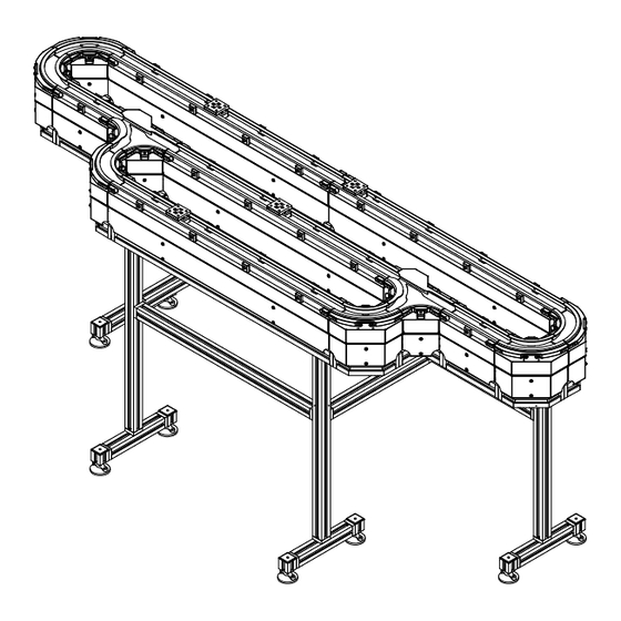
Page 120: System Stands
Figure 3-48. [9.8] TYPICAL Puck Top [9.47] Motor 240.5 Motor Mount Beam System Height Table 4-4 Leg Height ±12 Floor [4.9] [2.0] Stand Width Table 4-5 Figure 3-47: System Stand MagneMotion Rockwell Automation Publication MMI-UM002F-EN-P - October 2022... -
Page 121: Typical Leg Installation
Design Guidelines Transport System Design 550 mm Two Legs 50 mm Single Leg Figure 3-48: Typical Leg Installation MagneMover LITE User Manual Rockwell Automation Publication MMI-UM002F-EN-P - October 2022... -
Page 122: Custom Motor Mounting
NOTE: For systems that use railless motors, the V-braces are attached to the top of the motor body. For straight motors, the V-braces are attached to both sides of the motor. For curve motors, the V-braces are only attached to the outside of the motor. MagneMotion Rockwell Automation Publication MMI-UM002F-EN-P - October 2022... - Page 123 Once all motor mounts are secured to the motor mounting surface, make sure that the vehicle (puck) is able to travel across all motors and joints with no apparent binding. If any binding is detected, make adjustments as required to minimize the binding. MagneMover LITE User Manual Rockwell Automation Publication MMI-UM002F-EN-P - October 2022...
-
Page 124: Puck Limits
Load Overhang Length Carrier Figure 3-50: Puck Carrier Overhang Table 3-4: Single Glide Puck Carrier Overhang Limits Overhang Length (mm) Maximum Load (g) <10 1000 MagneMotion Rockwell Automation Publication MMI-UM002F-EN-P - October 2022... -
Page 125: High Inertia Payloads
This erratic behavior becomes worse as the mass or velocity is increased. Use a high payload switch (shown in Figure 4-27 Figure 4-30) to help avoid some of the erratic motion when moving through a switch. MagneMover LITE User Manual Rockwell Automation Publication MMI-UM002F-EN-P - October 2022... -
Page 126: Transport System Options
Precision Rails Spine Plate Support Post Post Mount Figure 3-51: Precision Rail Option MagneMotion Rockwell Automation Publication MMI-UM002F-EN-P - October 2022... -
Page 127: Precision Rails
NOTICE The precision rails must always be lubricated with a thin coating of oil to provide proper operation and environmental protection, see Lubricate the Precision Rails on page 292. MagneMover LITE User Manual Rockwell Automation Publication MMI-UM002F-EN-P - October 2022... -
Page 128: Spine Plates
Left Joint Straight to Curve Right Joint Curve to Curve Left Joint Curve to Curve Right Joint Straight, Joint Straight, No Joint 180º Curve No Joint Figure 3-53: Precision Rail Spine Plates MagneMotion Rockwell Automation Publication MMI-UM002F-EN-P - October 2022... -
Page 129: Support Post Assembly
MagneMover LITE railless motors. Spine Plate Mounting Surface Support Post Support Post Mount Figure 3-54: Precision Rail Support Post MagneMover LITE User Manual Rockwell Automation Publication MMI-UM002F-EN-P - October 2022... -
Page 130: Precision Rail Vehicles
Mounting Plate Vehicle Body Bearings Magnet Array Figure 3-55: Precision Rail Single Array Vehicle Mounting Plate Vehicle Body Bearings Magnet Array Figure 3-56: Precision Rail Dual Array Vehicle MagneMotion Rockwell Automation Publication MMI-UM002F-EN-P - October 2022... -
Page 131: Precision Rail Installation
49.00 [1.929] Single Array Vehicle 1.50 [0.059] Rail Array Motor Support Post Assembly Motor Mount All Dimensions in Millimeters [Inches] Figure 3-57: Precision Rail to Motor Reference Diagram MagneMover LITE User Manual Rockwell Automation Publication MMI-UM002F-EN-P - October 2022... -
Page 132: Precision Rail Lubrication
This configuration requires a second vehicle with a lubricator for the other side of the rail. Lubricator Figure 3-58: Lubricator on Single Array Vehicle MagneMotion Rockwell Automation Publication MMI-UM002F-EN-P - October 2022... -
Page 133: Precision Rail System With Lubrication Pump System
Install the Optional Precision Rail Lubrication Pump System on page 293. Lubrication Port (2X One Each Side) Lubrication Distribution Tubing Lubrication Pump Figure 3-59: Precision Rail System with Lubrication Pump System MagneMover LITE User Manual Rockwell Automation Publication MMI-UM002F-EN-P - October 2022... -
Page 134: Precision Locator
The locator mechanism uses two rocker arms with precision pins that mate with precision bushings in the pallet to lock the pallet into posi- tion. MagneMotion Rockwell Automation Publication MMI-UM002F-EN-P - October 2022... -
Page 135: Locator Stand
Vertical load on the pallet while clamped in the precision locator is limited only by the physical properties of the materials of the pallet and stand and not by the locating mechanism. MagneMover LITE User Manual Rockwell Automation Publication MMI-UM002F-EN-P - October 2022... -
Page 136: Precision Locator Pallet Design Details
SECTION C-C BUSHING MOUNT FEATURES ROTATED 90° CW SKI MOUNT FEATURES Ø9.10 30.00 90° (2.3) 3.25 Ø4.5 Ø8.50 SECTION B-B ROTATED 90° CW MAGNET ARRAY FEATURES Figure 3-61: Precision Locator Pallet Design Details MagneMotion Rockwell Automation Publication MMI-UM002F-EN-P - October 2022... -
Page 137: Precision Locator Installation
A pneumatic block diagram for the precision locator that uses a 5/2 valve is provided in Figure 3-63. Oper- ation of the valve is described after the figure. MagneMover LITE User Manual Rockwell Automation Publication MMI-UM002F-EN-P - October 2022... -
Page 138: Precision Locator Pneumatic Block Diagram
Pallet Engaged – Air flows from Port 1 (inlet) to Port 4 and is supplied to the Precision Loca- tor cylinder to move it to the extended position. As the cylinder moves, air returns from the cylinder to Port 2 and exhausts at Port 3. MagneMotion Rockwell Automation Publication MMI-UM002F-EN-P - October 2022... -
Page 139: Transport System Configuration
Figure 3-64: Straight Track Configuration • Node types at the beginning of a path: Simple, Relay, Terminus, Gateway. • Node types at the end of a path: Relay, Terminus, Gateway. MagneMover LITE User Manual Rockwell Automation Publication MMI-UM002F-EN-P - October 2022... -
Page 140: Curve Track Configuration
Top View Figure 3-65: Curve Track Configuration • Node types at the beginning of a path: Simple, Relay, Terminus, Gateway. • Node types at the end of a path: Relay, Terminus, Gateway. MagneMotion Rockwell Automation Publication MMI-UM002F-EN-P - October 2022... -
Page 141: Switch Configuration
Provides a diverge from one path into two (single entry, curve exit, straight exit). • Provides a merge of two paths into one (straight entry, curve entry, merged exit). MagneMover LITE User Manual Rockwell Automation Publication MMI-UM002F-EN-P - October 2022... - Page 142 Design Guidelines This page intentionally left blank. MagneMotion Rockwell Automation Publication MMI-UM002F-EN-P - October 2022...
-
Page 143: Specifications And Site Requirements
• Mechanical specifications for all MagneMover LITE components, including dimen- sions. • Electrical specifications for power and communication, including connector pinouts. • Site requirements, including environmental and service access. MagneMover LITE User Manual Rockwell Automation Publication MMI-UM002F-EN-P - October 2022... -
Page 144: Motor Types
(tandem) vehicle or a curved motor decreases the number of vehicles that are allowed per meter. † Nominal vehicle gap (distance between the magnet array and the motor) is 1 mm for G3 magnet arrays and 1.5 mm for G4.2 and later magnet arrays. MagneMotion Rockwell Automation Publication MMI-UM002F-EN-P - October 2022... -
Page 145: Magnemover Lite Gen 4 Motors Using Rs-422 Communication
90° Curve Aluminum 700-1308-43 90° Curve Stainless Steel 700-1308-44 90° Curve None 700-1308-45 90° Curve Aluminum 700-1308-12 90° Curve None MMI-MML-CURV-NR-SER-SYNCAC Switch, Left Aluminum 700-1308-80 Switch, Left Stainless Steel 700-1308-81 MagneMover LITE User Manual Rockwell Automation Publication MMI-UM002F-EN-P - October 2022... -
Page 146: Magnemover Lite Gen 4 Motors Using Ethernet Communication
250 mm, Straight Stainless Steel 700-1708-24 250 mm, Straight None 700-1708-25 250 mm, Straight Aluminum 700-1708-23-AC 250 mm, Straight Stainless Steel 700-1708-24-AC 250 mm, Straight None 700-1708-25-AC 90° Curve Aluminum 700-1708-40 90° Curve Stainless Steel 700-1708-41 MagneMotion Rockwell Automation Publication MMI-UM002F-EN-P - October 2022... - Page 147 Switch, Left Aluminum 700-1708-80 Switch, Left Stainless Steel 700-1708-81 Switch, Right Aluminum 700-1708-60 Switch, Right Stainless Steel 700-1708-61 Switch, High Aluminum 700-1708-82 Payload, Left Switch, High Aluminum 700-1708-62 Payload, Right MagneMover LITE User Manual Rockwell Automation Publication MMI-UM002F-EN-P - October 2022...
-
Page 148: Mechanical Specifications
Silicone 737 and 734. • A286 SS. • EPDM (synthetic rubber). • 300 Series SS, Passivated. • A4 SS. • 303 SS. • 304L SS, Nickel plate (SS rails). • 304 SS. MagneMotion Rockwell Automation Publication MMI-UM002F-EN-P - October 2022... -
Page 149: Mm Rs-422 Air-Cooled Motor Mechanical Drawing
EPDM (synthetic rubber). • 303 SS. • A4 SS. • 304 SS. • 316 SS. • 303 SS, Nickel plate (air ports). • Steel, Zinc plate (air port plug). MagneMover LITE User Manual Rockwell Automation Publication MMI-UM002F-EN-P - October 2022... -
Page 150: Mm Railless Rs-422 Motor Mechanical Drawing
Copper alloy, Nickel plate. • 316L SS, Passivated. • Zinc, Nickel plate. • A286 SS. ® • Dow Corning Silicone 737 and 734. • 300 Series SS, Passivated. • A4 SS. • 303 SS. MagneMotion Rockwell Automation Publication MMI-UM002F-EN-P - October 2022... -
Page 151: Mm Railless Rs-422 Air-Cooled Motor Mechanical Drawing
Silicone 737 and 734. • 300 Series SS, Passivated. • A4 SS. • 303 SS. • 303 SS, Nickel plate (air ports). • Steel, Zinc plate (air port plug). MagneMover LITE User Manual Rockwell Automation Publication MMI-UM002F-EN-P - October 2022... -
Page 152: Mm Ethernet Motor Mechanical Drawing
• Dow Corning Silicone 737 and 734. • 300 Series SS, Passivated. • EPDM (synthetic rubber). • 303 SS. • A4 SS. • 304 SS. • 304L SS, Nickel plate (SS rails). MagneMotion Rockwell Automation Publication MMI-UM002F-EN-P - October 2022... -
Page 153: Mm Ethernet Air-Cooled Motor Mechanical Drawing
303 SS. • EPDM (synthetic rubber). • 304 SS. • A4 SS. • 303 SS, Nickel plate (air ports) • 316 SS. • Steel, Zinc plate (air port plug). MagneMover LITE User Manual Rockwell Automation Publication MMI-UM002F-EN-P - October 2022... -
Page 154: Mm Railless Ethernet Motor Mechanical Drawing
316L SS, Passivated. • Brass, Nickel plate. • A286 SS. • Zinc, Nickel plate. • 300 Series SS, Passivated. ® • Dow Corning Silicone 737 and 734. • 303 SS • A4 SS. MagneMotion Rockwell Automation Publication MMI-UM002F-EN-P - October 2022... -
Page 155: Mm Railless Ethernet Air-Cooled Motor Mechanical Drawing
® • Dow Corning Silicone 737 and 734. • 303 SS, Nickel plate (air ports). • A4 SS. • Steel, Zinc plate (air port plug). • 316L SS, Passivated. MagneMover LITE User Manual Rockwell Automation Publication MMI-UM002F-EN-P - October 2022... -
Page 156: 250 Millimeter Motors
Silicone 737 and 734. • A286 SS. • EPDM (synthetic rubber). • 300 Series SS, Passivated. • A4 SS. • 303 SS. • 304L SS, Nickel plate (SS rails). • 304 SS. MagneMotion Rockwell Automation Publication MMI-UM002F-EN-P - October 2022... - Page 157 EPDM (synthetic rubber). • 303 SS. • A4 SS. • 304 SS. • 316 SS. • 303 SS, Nickel plate (air ports). • Steel, Zinc plate (air port plug). MagneMover LITE User Manual Rockwell Automation Publication MMI-UM002F-EN-P - October 2022...
- Page 158 Copper alloy, Nickel plate. • 316L SS, Passivated. • Zinc, Nickel plate. • A286 SS. ® • Dow Corning Silicone 737 and 734. • 300 Series SS, Passivated. • A4 SS. • 303 SS. MagneMotion Rockwell Automation Publication MMI-UM002F-EN-P - October 2022...
- Page 159 Silicone 737 and 734. • 300 Series SS, Passivated. • A4 SS. • 303 SS. • 303 SS, Nickel plate (air ports). • Steel, Zinc plate (air port plug). MagneMover LITE User Manual Rockwell Automation Publication MMI-UM002F-EN-P - October 2022...
- Page 160 • Dow Corning Silicone 737 and 734. • 300 Series SS, Passivated. • EPDM (synthetic rubber). • 303 SS. • A4 SS. • 304 SS. • 304L SS, Nickel plate (SS rails). MagneMotion Rockwell Automation Publication MMI-UM002F-EN-P - October 2022...
- Page 161 303 SS. • EPDM (synthetic rubber). • 304 SS. • A4 SS. • 303 SS, Nickel plate (air ports) • 316 SS. • Steel, Zinc plate (air port plug). MagneMover LITE User Manual Rockwell Automation Publication MMI-UM002F-EN-P - October 2022...
- Page 162 316L SS, Passivated. • Brass, Nickel plate. • A286 SS. • Zinc, Nickel plate. • 300 Series SS, Passivated. ® • Dow Corning Silicone 737 and 734. • 303 SS. • A4 SS. MagneMotion Rockwell Automation Publication MMI-UM002F-EN-P - October 2022...
- Page 163 ® • Dow Corning Silicone 737 and 734. • 303 SS, Nickel plate (air ports). • A4 SS. • Steel, Zinc plate (air port plug). • 316L SS, Passivated. MagneMover LITE User Manual Rockwell Automation Publication MMI-UM002F-EN-P - October 2022...
-
Page 164: 125 Millimeter Radius 90° Curve Motors
Silicone 737 and 734. • A286 SS. • EPDM (synthetic rubber). • 300 Series SS, Passivated. • A4 SS. • 303 SS. • 304L SS, Nickel plate (SS rails). • 304 SS. MagneMotion Rockwell Automation Publication MMI-UM002F-EN-P - October 2022... -
Page 165: Mm R 90° Curve Rs-422 Air-Cooled Motor Mechanical Drawing
EPDM (synthetic rubber). • 303 SS. • A4 SS. • 304 SS. • 316 SS. • 303 SS, Nickel plate (air ports). • Steel, Zinc plate (air port plug). MagneMover LITE User Manual Rockwell Automation Publication MMI-UM002F-EN-P - October 2022... -
Page 166: Mm R 90° Curve Railless Rs-422 Motor Mechanical Drawing
Copper alloy, Nickel plate. • 316L SS, Passivated. • Zinc, Nickel plate. • A286 SS. ® • Dow Corning Silicone 737 and 734. • 300 Series SS, Passivated. • A4 SS. • 303 SS. MagneMotion Rockwell Automation Publication MMI-UM002F-EN-P - October 2022... -
Page 167: Mm R 90° Curve Railless Rs-422 Air-Cooled Motor Mechanical Drawing
Silicone 737 and 734. • 300 Series SS, Passivated. • A4 SS. • 303 SS. • 303 SS, Nickel plate (air ports). • Steel, Zinc plate (air port plug). MagneMover LITE User Manual Rockwell Automation Publication MMI-UM002F-EN-P - October 2022... -
Page 168: Mm R 90° Curve Ethernet Motor Mechanical Drawing
• Dow Corning Silicone 737 and 734. • 300 Series SS, Passivated. • EPDM (synthetic rubber). • 303 SS. • A4 SS. • 304 SS. • 304L SS, Nickel plate (SS rails). MagneMotion Rockwell Automation Publication MMI-UM002F-EN-P - October 2022... -
Page 169: Mm R 90° Curve Ethernet Air-Cooled Motor Mechanical Drawing
303 SS. • EPDM (synthetic rubber). • 304 SS. • A4 SS. • 303 SS, Nickel plate (air ports). • 316 SS. • Steel, Zinc plate (air port plug). MagneMover LITE User Manual Rockwell Automation Publication MMI-UM002F-EN-P - October 2022... -
Page 170: Mm R 90° Railless Curve Ethernet Motor Mechanical Drawing
316L SS, Passivated. • Brass, Nickel plate. • A286 SS. • Zinc, Nickel plate. • 300 Series SS, Passivated. ® • Dow Corning Silicone 737 and 734. • 303 SS • A4 SS. MagneMotion Rockwell Automation Publication MMI-UM002F-EN-P - October 2022... -
Page 171: Mm R 90° Railless Curve Ethernet Air-Cooled Motor Mechanical Drawing
® • Dow Corning Silicone 737 and 734. • 303 SS, Nickel plate (air ports). • A4 SS. • Steel, Zinc plate (air port plug). • 316L SS, Passivated. MagneMover LITE User Manual Rockwell Automation Publication MMI-UM002F-EN-P - October 2022... -
Page 172: 90° Left Switches
303 SS. ® • Dow Corning Silicone 737 and 734. • 304 SS. • EPDM (synthetic rubber). • 440 SS. • A4 SS. • 18-8 SS. • 303 SS, Nickel plate (SS rails). MagneMotion Rockwell Automation Publication MMI-UM002F-EN-P - October 2022... -
Page 173: Left Ethernet Switch Mechanical Drawing
Dow Corning Silicone 737 and 734. • 440 SS. • EPDM (synthetic rubber). • 400 Series SS. • A4 SS. • 18-8 SS. • 303 SS, Nickel plate (SS rails). MagneMover LITE User Manual Rockwell Automation Publication MMI-UM002F-EN-P - October 2022... -
Page 174: Left Ethernet High Payload Switch Mechanical Drawing
Silicone 737 and 734. • A286 SS. • EPDM (synthetic rubber). • Black Oxide Finish Alloy Steel. ® • White Vinyl Nitrile Rubber. • Tivar 1000. • A4 SS. • Nitrile Rubber. • 316 SS. MagneMotion Rockwell Automation Publication MMI-UM002F-EN-P - October 2022... -
Page 175: 90° Right Switches
Dow Corning Silicone 737 and 734. • 304 SS. • EPDM (synthetic rubber). • 440 SS. • A4 SS. • 18-8 SS. • 303 SS, Nickel plate (SS rails). MagneMover LITE User Manual Rockwell Automation Publication MMI-UM002F-EN-P - October 2022... -
Page 176: Right Ethernet Switch Mechanical Drawing
® • Dow Corning Silicone 737 and 734. • 440 SS. • EPDM (synthetic rubber). • 400 Series SS. • A4 SS. • 18-8 SS. • 303 SS, Nickel plate (SS rails). MagneMotion Rockwell Automation Publication MMI-UM002F-EN-P - October 2022... -
Page 177: Right Ethernet High Payload Switch Mechanical Drawing
A286 SS. • EPDM (synthetic rubber). • Black Oxide Finish Alloy Steel. ® • White Vinyl Nitrile Rubber. • Tivar 1000. • A4 SS. • Nitrile Rubber. • 316 SS. MagneMover LITE User Manual Rockwell Automation Publication MMI-UM002F-EN-P - October 2022... -
Page 178: Standard Motor Mount Bracket
9.00[0.354] THRU .625 15.88 All Dimensions in Millimeters [Inches] Figure 4-31: Standard Motor Mount Bracket Mechanical Drawing Exposed Materials • 6063-T5 AL, Anodized per MIL-A-8625F, Type II, Class 2. • 304 Stainless Steel. MagneMotion Rockwell Automation Publication MMI-UM002F-EN-P - October 2022... -
Page 179: V-Brace Kits
Anodized per payload switch (long flip- VHPS-0 MIL-A-8625-F, Type III, per) with aluminum rails Includes one 200-2450-00 key & Class 1, Non-dyed. two M6 x 12 mm screws MagneMover LITE User Manual Rockwell Automation Publication MMI-UM002F-EN-P - October 2022... -
Page 180: Stand System
Table 4-4 60 ±12 All Dimensions in Millimeters Figure 4-33: Stand System Mechanical Drawing Exposed Materials • Galvanized Steel. • Zinc, Electrophoretically coated. • 6060 T66 Aluminum, Anodized. • PA6 Nylon. • Rubber. MagneMotion Rockwell Automation Publication MMI-UM002F-EN-P - October 2022... -
Page 181: Stand System Heights
1300 mm [51.2 in] 200-1991-5X Maximum number of motors supported, minimum motor spacing is 250 mm center-to-center. † The “X” in the catalog number represents the stand height (see Table 4-4) MagneMover LITE User Manual Rockwell Automation Publication MMI-UM002F-EN-P - October 2022... -
Page 182: Glide Pucks
Weight: 0.43 kg [0.9 lb] All Dimensions in Millimeters [Inches] Figure 4-34: Glide Puck Mechanical Drawing (G5) Exposed Materials • Stainless Steel. • 316/316L/316L #2 Stainless Steel. • PEEK/PTFE. • UHMW Polyethylene. MagneMotion Rockwell Automation Publication MMI-UM002F-EN-P - October 2022... -
Page 183: Wheeled Pucks
7075-T651 Aluminum, Anodized per MIL-A8625, Type III, Class 2, Black. • 6061-T6 Aluminum, Natural. • 174-PH/18-8/304/316/440C Stainless Steel. • PEEK. • Polyurethane. • Stainless Steel. • 316L/316L #2 Stainless Steel. • UHMW Polyethylene. MagneMover LITE User Manual Rockwell Automation Publication MMI-UM002F-EN-P - October 2022... -
Page 184: Wheel Puck Mechanical Drawing
7075-T651 Aluminum, Anodized per MIL-A8625, Type III, Class 2, Black. • 6061-T6 Aluminum, Natural. • 174-PH/18-8/304/316/440C Stainless Steel. • PEEK. • Polyurethane. • Stainless Steel. • 316L/316L #2 Stainless Steel. • UHMW Polyethylene. MagneMotion Rockwell Automation Publication MMI-UM002F-EN-P - October 2022... -
Page 185: Tandem Glide Pucks
Figure 4-37: Tandem Glide Puck Mechanical Drawing (G5) Exposed Materials • Stainless Steel. • 316/316L/316L #2 Stainless Steel. • PEEK/PTFE. • UHMW Polyethylene. ® • Delrin FG150. • Acetal. MagneMover LITE User Manual Rockwell Automation Publication MMI-UM002F-EN-P - October 2022... -
Page 186: Tandem Wheeled Pucks
6061-T6 Aluminum, Anodized per MIL-A8625, Type III, Class 2, Black. • 304 Stainless Steel. • 174-PH/18-8/304/316/440C Stainless Steel. • PEEK. • Polyurethane. • Igus® L280. • 316L/316L #2 Stainless Steel. • UHMW Polyethylene. MagneMotion Rockwell Automation Publication MMI-UM002F-EN-P - October 2022... -
Page 187: Magnet Arrays
Weight: 0.37 kg [0.8 lb] All Dimensions in Millimeters [Inches] Figure 4-39: Magnet Array Mechanical Drawing (G4.2) Exposed Materials • Stainless Steel. • 316L/316L #2 Stainless Steel. • UHMW Polyethylene. MagneMover LITE User Manual Rockwell Automation Publication MMI-UM002F-EN-P - October 2022... -
Page 188: Mm Lite Power Supply
All vents must be clear for unobstructed airflow. Ingress Protection Rating: IP30. Exposed Materials The power supply provides openings for airflow and must not be located where harsh condi- tions exist. MagneMotion Rockwell Automation Publication MMI-UM002F-EN-P - October 2022... -
Page 189: Precision Rail Option
The precision rails must always be lubricated with a thin coating of oil to provide proper operation and environmental protection. Exposed Materials • 420 Series Stainless Steel or High Carbon Steel. MagneMover LITE User Manual Rockwell Automation Publication MMI-UM002F-EN-P - October 2022... -
Page 190: Precision Rail Types And Lengths
110-0126-00 3250 mm 110-0126-01 Curved 90° 175.5 mm R 110-0097-00 90° 175.5 mm R 110-0097-01 Rail 180° 175.5 mm R 110-0106-00 180° 175.5 mm R 110-0106-01 Includes features for attaching rail lubricator. MagneMotion Rockwell Automation Publication MMI-UM002F-EN-P - October 2022... -
Page 191: Precision Rail Single Array Vehicle
6061-T6 AL, Anodized per MIL-A8625-F, Type II, Class 2, Black. • Stainless Steel. • 316L/316L #2 Stainless Steel. • 440C Stainless Steel. • UHMW Polyethylene. • Nitrile. • Plastic. ™ • Mobilgear 600 XP Oil. MagneMover LITE User Manual Rockwell Automation Publication MMI-UM002F-EN-P - October 2022... -
Page 192: Precision Rail Dual Array Vehicle
6061-T6 AL, Anodized per MIL-A8625-F, Type II, Class 2, Black. • Stainless Steel. • 316L/316L #2 Stainless Steel. • 440C Stainless Steel. • UHMW Polyethylene. • Nitrile. • Plastic. ™ • Mobilgear 600 XP Oil. MagneMotion Rockwell Automation Publication MMI-UM002F-EN-P - October 2022... -
Page 193: Precision Rail Support Post Assembly
6061-T6 AL, Powder coated. • 304 Stainless Steel. • ABS V0 Composite, Black. • Steel, Zinc plate. • 18-8 Stainless Steel. • 304 Stainless Steel. A2 Stainless Steel. • • Galvanized Steel. MagneMover LITE User Manual Rockwell Automation Publication MMI-UM002F-EN-P - October 2022... -
Page 194: Spine Plates
6X R4 125.0° 2X 54.98 64.98 141.5° 94.99 114.98 R169.88 Left 138.90 150.0 128.5° [0.25] 6.35 700-1622-03 Right All Dimensions in Millimeters Figure 4-45: Precision Rail Straight to Curve, Spine Plates, Mechanical Drawing MagneMotion Rockwell Automation Publication MMI-UM002F-EN-P - October 2022... -
Page 195: Precision Rail Curve To Curve, Spine Plates, Mechanical Drawing
2X 95.00 76.40 75.00 141.5° R169.88 35.00 11.08 Left 128.5° [0.25] 6.35 700-1622-04 Right All Dimensions in Millimeters Figure 4-46: Precision Rail Curve to Curve, Spine Plates, Mechanical Drawing MagneMover LITE User Manual Rockwell Automation Publication MMI-UM002F-EN-P - October 2022... -
Page 196: Precision Rail Straight, No Joint, Spine Plate, Mechanical Drawing
Figure 4-47: Precision Rail Straight, No Joint, Spine Plate, Mechanical Drawing 700-1622-05 125.0° 2X 54.98 64.98 73.58 141.5° 124.98 132.0 [0.25] 6.35 All Dimensions in Millimeters Figure 4-48: Precision Rail Straight, With Joint, Spine Plate, Mechanical Drawing MagneMotion Rockwell Automation Publication MMI-UM002F-EN-P - October 2022... -
Page 197: Precision Rail Curve, 180°, No Joint, Spine Plate, Mechanical Drawing
700-1622-06 114.2° 110.30 100.42 2X 95.00 76.40 141.5° R169.88 9.58 128.5° [0.25] 6.35 All Dimensions in Millimeters Figure 4-49: Precision Rail Curve, 180°, No Joint, Spine Plate, Mechanical Drawing MagneMover LITE User Manual Rockwell Automation Publication MMI-UM002F-EN-P - October 2022... -
Page 198: Precision Rail Lubrication System
Kluber 4 UH1-68N oil. • Technical Polymer. • Fluoropolymer Tubing. • Nitrile rubber. • 304 SS. • Brass, Nickel plate. • Brass. • Nylon Plastic. • Plastic. • Drive housing with LCD. MagneMotion Rockwell Automation Publication MMI-UM002F-EN-P - October 2022... -
Page 199: Precision Locator Option
6061-T6 AL, Anodized per MIL-A-8625F, Type II, Class 2, Blue. • 18-8 (A2) Hardened Stainless Steel with Thin Dense Chrome plating. • UHMW, WHITE • SBR Rubber. • IGUS iglide® L280. • Music Wire. MagneMover LITE User Manual Rockwell Automation Publication MMI-UM002F-EN-P - October 2022... -
Page 200: Precision Locator Actuator
Shroud Kit, 1-up 700-1677-01 Pinning device. no cover, with 700-1670-01 Shroud Kit, 2-up, 100 mm pitch 700-1677-02 actuation sensors Shroud Kit, 3-up, 100 mm pitch 700-1677-03 Shroud Kit, 4-up, 100 mm pitch 700-1677-04 MagneMotion Rockwell Automation Publication MMI-UM002F-EN-P - October 2022... -
Page 201: Stand Assembly
Figure 4-52: Standard Precision Locator Stand Mechanical Drawing Exposed Materials • 6061-T6 Aluminum, Anodized per MIL-A8625-F, Type II, Class 1, Non-dyed. ® • Tivar H.O.T. • 18-8 (A2) Stainless Steel. • 316 Stainless Steel. MagneMover LITE User Manual Rockwell Automation Publication MMI-UM002F-EN-P - October 2022... -
Page 202: Precision Locator Stand
Stand Style Catalog # 1-up, 1 Puck 700-1666-01 2-up, 2 Pucks, 100 mm pitch 700-1666-02 3-up, 3 Pucks, 100 mm pitch 700-1666-03 4-up, 4 Pucks, 100 mm pitch 700-1666-04 1-up, Tandem Puck 700-1666-09 MagneMotion Rockwell Automation Publication MMI-UM002F-EN-P - October 2022... -
Page 203: Adjustable Motor Mount Bracket
Figure 4-53: Adjustable Motor Mount Bracket Mechanical Drawing Exposed Materials • 6063-T5 AL, Anodized per MIL-A-8625F, Type II, Class 2. • 304 Stainless Steel. • 18-8 Stainless Steel. • Nylon. MagneMover LITE User Manual Rockwell Automation Publication MMI-UM002F-EN-P - October 2022... -
Page 204: Pallet
6061-T6 Aluminum, Hardcoat Anodized per MIL-A8625-F, Type III, Class 2, Black. • 18-8 (A2) Hardened Stainless Steel with Thin Dense Chrome plating. • Stainless Steel. • 316/316L/316L #2 Stainless Steel. • PEEK/PTFE. • UHMW Polyethylene. MagneMotion Rockwell Automation Publication MMI-UM002F-EN-P - October 2022... -
Page 205: Precision Locator Tandem Glide Puck With Basic Pallet Mechanical Drawing
6061-T6 Aluminum, Hardcoat Anodized per MIL-A8625-F, Type III, Class 2, Black. • 18-8 (A2) Hardened Stainless Steel with Thin Dense Chrome plating. • Stainless Steel. • 316/316L/316L #2 Stainless Steel. • PEEK/PTFE. • UHMW Polyethylene. MagneMover LITE User Manual Rockwell Automation Publication MMI-UM002F-EN-P - October 2022... -
Page 206: Electrical Specifications
Table 4-9: MagneMover LITE Motor and Switch Power Requirements Component Maximum Power 250 mm Motor 1000 mm Motor 10 W MagneMotion Rockwell Automation Publication MMI-UM002F-EN-P - October 2022... - Page 207 NOTICE Any user-supplied power supply must be NRTL/ATL approved. NOTICE Hot-plugging of either power source to the motors is not rec- ommended. MagneMover LITE User Manual Rockwell Automation Publication MMI-UM002F-EN-P - October 2022...
-
Page 208: Straight And Curve Motors
The Sync Option Connector is only present if the Synchronization option is installed. If the Sync Option con- nector is not installed, a low-profile cap is installed to cover the connector mounting hole. MagneMotion Rockwell Automation Publication MMI-UM002F-EN-P - October 2022... -
Page 209: Magnemover Lite Motor Rs-422 Pinouts
Table 4-12: MagneMover LITE Motor Power Pinouts Keyway Mini-Conn-X, 4-Pin, Plug V+ Propulsion V+ Logic V- Return Table 4-13: MagneMover LITE Sync Pinouts Keyway Micro-Mizer, 8-Pin, Plug SIMO SCLK SOMI — RESET MagneMover LITE User Manual Rockwell Automation Publication MMI-UM002F-EN-P - October 2022... -
Page 210: Magnemover Lite Ethernet Motor Electrical Connections
The Sync Option Connector is only present if the Synchronization option is installed. If the Sync Option con- nector is not installed, a low-profile cap is installed to cover the connector mounting hole. MagneMotion Rockwell Automation Publication MMI-UM002F-EN-P - October 2022... -
Page 211: Magnemover Lite Motor Ethernet Pinout
Table 4-15: MagneMover LITE Motor Ethernet Pinout 700-1573-00 M12 Eurofast, FKFDD, Socket — — — — Table 4-16: MagneMover LITE Motor Power Pinouts Keyway Mini-Conn-X, 4-Pin, Plug V+ Propulsion V+ Logic V- Return MagneMover LITE User Manual Rockwell Automation Publication MMI-UM002F-EN-P - October 2022... -
Page 212: Magnemover Lite Sync Pinouts
Specifications and Site Requirements Electrical Specifications Table 4-17: MagneMover LITE Sync Pinouts Keyway Micro-Mizer, 8-Pin, Plug SIMO SCLK SOMI — RESET MagneMotion Rockwell Automation Publication MMI-UM002F-EN-P - October 2022... -
Page 213: Switches
M8 Nano-Mizer, 4-Pin, Plug RS-422 communication M8 Nano-Mizer, 4-Pin, Plug +36V DC ±10%, 1.5 A typical, 5.0 A max Mini-Conn-X, 4-Pin, Plug Ethernet – 10/100/1000 Base-Tx RJ45, Socket, IP-67 MagneMover LITE User Manual Rockwell Automation Publication MMI-UM002F-EN-P - October 2022... -
Page 214: Magnemover Lite Switch Rs-422 Pinouts
Table 4-20: MagneMover LITE Switch Power Pinouts Keyway Mini-Conn-X, 4-Pin, Plug V+ Propulsion V+ Logic V- Return Table 4-21: MagneMover LITE Switch Ethernet Pinout LAN – RJ45, Socket — — — — MagneMotion Rockwell Automation Publication MMI-UM002F-EN-P - October 2022... -
Page 215: Magnemover Lite Ethernet Switch Electrical Connections
+36V DC ±10%, 1.5 A typical, 5.0 A max Mini-Conn-X, 4-Pin, Plug Table 4-23: MagneMover LITE Switch Power Pinouts Keyway Mini-Conn-X, 4-Pin, Plug V+ Propulsion V+ Logic V- Return MagneMover LITE User Manual Rockwell Automation Publication MMI-UM002F-EN-P - October 2022... -
Page 216: Magnemover Lite Switch Ethernet Pinout
Specifications and Site Requirements Electrical Specifications Table 4-24: MagneMover LITE Switch Ethernet Pinout 700-1573-00 M12 Eurofast, FKFDD, Socket — — — — MagneMotion Rockwell Automation Publication MMI-UM002F-EN-P - October 2022... -
Page 217: Mm Lite Power Supply
LITE Power supply (10 per 300 W DC output). NOTICE The MM LITE Power Supply uses an internal NRTL/ATL approved power source. If a user-supplied power supply is used in its place, it must be NRTL/ATL approved. MagneMover LITE User Manual Rockwell Automation Publication MMI-UM002F-EN-P - October 2022... -
Page 218: Mm Lite Power Supply Electrical Connections And Indicators
Table 4-26: MM LITE Power Supply Indicators Label Description Indicator Type LOGIC ON – Indicates that motor logic power is on. Green Light PROPULSION ON – Indicates that motor propulsion power is on. Green Light MagneMotion Rockwell Automation Publication MMI-UM002F-EN-P - October 2022... -
Page 219: Mm Lite Power Supply Fuses
3.3…5.6V when the PS is on. The sinking current is 10 mA max- imum. † Can be shorted via a transistor to enable propulsion power. The sinking current is 20 mA maximum. MagneMover LITE User Manual Rockwell Automation Publication MMI-UM002F-EN-P - October 2022... -
Page 220: Ac Power Cable
There is a potential shock hazard if the MM LITE power sup- ply chassis and cover are not connected to an electrical safety ground via the safety ground in the AC input connector. MagneMotion Rockwell Automation Publication MMI-UM002F-EN-P - October 2022... -
Page 221: Motor Power Cables
Figure 4-61: MM LITE DC Power Cables Table 4-30: DC Power Cable Pinouts Keyway Keyway Individual Mini-Mizer, Mini-Mizer, Mini-Conn-X, Terminals 4-Pin, Socket 4-Pin, Plug 4-Pin, Socket V+ Propulsion Black V+ Logic White V- Return Green MagneMover LITE User Manual Rockwell Automation Publication MMI-UM002F-EN-P - October 2022... -
Page 222: Dc Enable
This jumper (provided by MagneMotion) is used in place of the DC Enable cable and is permanently plugged into J4 on the MM LITE power supply. 700-1288-00 Figure 4-63: DC Enable Jumper MagneMotion Rockwell Automation Publication MMI-UM002F-EN-P - October 2022... -
Page 223: Precision Rail Lubrication Pump
Table 4-32: Precision Rail Optional Lubricator Pump Controls Label Description Control Type — Set Button Push button Table 4-33: Precision Rail Optional Lubricator Pump Indicators Label Description Indicator Type — Display — Status MagneMover LITE User Manual Rockwell Automation Publication MMI-UM002F-EN-P - October 2022... -
Page 224: Precision Rail Lubrication Pump Connector
Figure 4-64. The indicators and display are used to set the operating configuration and monitor the pump status, see the manufacturers documentation for detailed information. MagneMotion Rockwell Automation Publication MMI-UM002F-EN-P - October 2022... -
Page 225: Precision Locator
Cylinder Down Sensor Connection M8 Locking, 3-Pin, Plug Table 4-36: Precision Locator Sensor Indicators Label Description Indicator Type — ON – Indicates that the sensor is active. Red Light MagneMover LITE User Manual Rockwell Automation Publication MMI-UM002F-EN-P - October 2022... -
Page 226: Precision Locator Sensor Pinout
Specifications and Site Requirements Electrical Specifications Table 4-37: Precision Locator Sensor Pinout Pin 3 Pin 1 Pin 4 M8, 3-Pin, Plug DC (+) DC (-) Output +24V DC max @ 40 mA maximum. MagneMotion Rockwell Automation Publication MMI-UM002F-EN-P - October 2022... -
Page 227: Pneumatic Specifications
1 psi specification. Pressurizing Supply air per ANSI 7.0.01-1996, Quality Standard for Instrument Air. Do not exceed 1.0 psig [6.9 kPa] inlet pressure. Plugged. MagneMover LITE User Manual Rockwell Automation Publication MMI-UM002F-EN-P - October 2022... -
Page 228: Precision Locator
Table 4-40: Precision Locator Connections Label Description Connector Type — Close Rc 1/8 in Thread (typically for 6 mm OD tube fitting) — Open Rc 1/8 in Thread (typically for 6 mm OD tube fitting) MagneMotion Rockwell Automation Publication MMI-UM002F-EN-P - October 2022... -
Page 229: Communication
There is one Host control connection and four Host status connections on the HLC. If a sec- ond Host attempts to connect to the Host control TCP/IP port, it causes the first Host to be dis- MagneMover LITE User Manual Rockwell Automation Publication MMI-UM002F-EN-P - October 2022... -
Page 230: Tcp/Ip Communication - Node Controller To Motor
Ethernet network wiring. The EtherNet/IP address that is used on the node con- troller that is configured as the HLC must be configured as specified in the Node Controller Interface User Manual, MMI-UM001. MagneMotion Rockwell Automation Publication MMI-UM002F-EN-P - October 2022... -
Page 231: Rs-232 Serial Interface Connection
(DE-9 socket) RS-422 port. However, a custom crossover adapter can be used to connect an RS-422 DE-9 connector of the wrong type to any port on the NC LITE node controller. MagneMover LITE User Manual Rockwell Automation Publication MMI-UM002F-EN-P - October 2022... -
Page 232: Motor To Motor
4-pin M8 socket on one end and a 4-pin M8 socket on the other end. One M8 socket plugs into the downstream communication port on the motor and the other M8 socket plugs into the upstream communication port on the next motor. MagneMotion Rockwell Automation Publication MMI-UM002F-EN-P - October 2022... -
Page 233: Ethernet Interface Connection
MMI-UM005, for cable and connection details. There is no need to construct the sync cables as all cabling is available for the transport system. Contact Technical Support for additional or replacement cables (see Rockwell Automation Support on page 486). MagneMover LITE User Manual Rockwell Automation Publication MMI-UM002F-EN-P - October 2022... -
Page 234: Site Requirements
Storage: -18…+50° C [0…122° F] Humidity: 85% Maximum (relative, noncondensing) Magnet Arrays, Pucks, Precision Rail Vehicles Temperature: Operating: 0…50° C [32…122° F] Storage: -18…+60° C [0…140° F] Humidity: 85% Maximum (relative, noncondensing) MagneMotion Rockwell Automation Publication MMI-UM002F-EN-P - October 2022... -
Page 235: Derating At High Altitude
Service to the MagneMover LITE transport system must have the appropriate circuit breaker rating. MagneMover LITE User Manual Rockwell Automation Publication MMI-UM002F-EN-P - October 2022... -
Page 236: Service Access
NOTE: The Exclusion Zones that are shown are for the MagneMover LITE transport system components only. Additional exclusion zones may be required based on the design of a custom vehicle and the material that the MM LITE transport system is moving. MagneMotion Rockwell Automation Publication MMI-UM002F-EN-P - October 2022... -
Page 237: Installation
Unpacking and inspection of the MagneMover LITE transport system components. • MagneMover LITE component installation including: hardware installation, facilities connections, and software installation and configuration. • Initial power-up and check-out. • Transport system testing using demo scripts. MagneMover LITE User Manual Rockwell Automation Publication MMI-UM002F-EN-P - October 2022... -
Page 238: Unpacking And Inspection
User manuals, drawings, and so on. Precision Rail Option • Straight and curve rails. • Post and post/mount assemblies. • Spine plates. • Vehicles. Precision Locator Option • Precision locator. • Locator stand. • Adjustable motor mounts. MagneMotion Rockwell Automation Publication MMI-UM002F-EN-P - October 2022... -
Page 239: Unpacking And Moving
To avoid damage to watches, instruments, electronics, and magnetic media, keep metal tools, metal objects, magnetic media (for example, memory disks/chips, credit cards, and tapes) and electronics away from the magnet arrays. MagneMover LITE User Manual Rockwell Automation Publication MMI-UM002F-EN-P - October 2022... - Page 240 Open each shipping package and verify the contents against the shipping documents. Carefully inspect the MagneMover LITE components and all additional items for signs of shipping damage. Move all items to their destination (see Transport System Installation on page 241). MagneMotion Rockwell Automation Publication MMI-UM002F-EN-P - October 2022...
-
Page 241: Transport System Installation
• Open-end wrench, 13 mm, thin (precision rail option only). • Ratcheting Hex wrenches; 10 mm, 13 mm, 14 mm, 17 mm. • 000-0616-00 – Motor Alignment Fixture, ML. MagneMover LITE User Manual Rockwell Automation Publication MMI-UM002F-EN-P - October 2022... -
Page 242: Installation Overview - User-Supplied Mounting
Continue assembling and installing sections of the track until the system is complete. MagneMotion Rockwell Automation Publication MMI-UM002F-EN-P - October 2022... -
Page 243: Installation Overview - Magnemotion Supplied Mounting
Make sure that there is sufficient space around the motor mounting surface for all connectors and for the bend radius of all cables. Install the power supplies, node controllers, network switches, and cables (see Install- ing Electronics on page 263). MagneMover LITE User Manual Rockwell Automation Publication MMI-UM002F-EN-P - October 2022... -
Page 244: Installation Overview - Magnemotion Precision Rails
Adjust the feet on the stand section to make sure that it is flat and level (see Leveling the MagneMover LITE on page 251). Secure the stand section to the floor or other equipment as required (see Securing the Transport System on page 252). MagneMotion Rockwell Automation Publication MMI-UM002F-EN-P - October 2022... - Page 245 307). Power up the system and check all operating features, safety features, and connections (see System Check-out on page 309) and install software (see System Power-up on page 310). MagneMover LITE User Manual Rockwell Automation Publication MMI-UM002F-EN-P - October 2022...
-
Page 246: Installation Overview - Magnemotion Precision Locator
Install the Motors on page 298). Install the pneumatic controls for the precision locators (see Install the Pneumatic Controls on page 299). Install the covers on the precision locators (see Install the Covers on page 301). MagneMotion Rockwell Automation Publication MMI-UM002F-EN-P - October 2022... -
Page 247: Stand System Installation
The Loctite must cure for 2 hours at 22° C [72° F] before using the transport system. Repeat Step 4 Step 5 as needed to assemble the beams into a section of the system layout. MagneMover LITE User Manual Rockwell Automation Publication MMI-UM002F-EN-P - October 2022... -
Page 248: Installing System Legs
Install and tighten the screws to 26 N•m [230 in•lb] with a 6 mm Hex bit. The Loctite must cure for 2 hours at 22° C [72° F] before using the transport system. MagneMotion Rockwell Automation Publication MMI-UM002F-EN-P - October 2022... -
Page 249: Legs On A Parallel Path Beam Assembly
NOTE: Make sure that the angle bracket is configured for 50 mm use by placing the inserts into the bracket with the hole in the insert to the outside of the bracket as shown in Figure 5-4. MagneMover LITE User Manual Rockwell Automation Publication MMI-UM002F-EN-P - October 2022... -
Page 250: Angle Bracket Assembly
The Loctite must cure for 2 hours at 22° C [72° F] before using the transport system. Verify that all legs are perpendicular to the beams using a machinist square. Once the stand assembly is complete, make sure that the transport system is properly located. MagneMotion Rockwell Automation Publication MMI-UM002F-EN-P - October 2022... -
Page 251: Leveling The Magnemover Lite
Adjust the feet on the legs as required to reach the required height with a 14 mm Hex wrench. Lock the feet into position by tightening the jam nut against the leg with a 17 mm Hex wrench. Repeat for each foot. MagneMover LITE User Manual Rockwell Automation Publication MMI-UM002F-EN-P - October 2022... -
Page 252: Securing The Transport System
M8 screws to 26 N•m [230 in•lb] with a 6 mm Hex bit. The Loctite must cure for 2 hours at 22° C [72° F] before using the transport system. Secure the bracket to the floor. MagneMotion Rockwell Automation Publication MMI-UM002F-EN-P - October 2022... -
Page 253: Foot Tie-Down
Secure the feet on the MagneMover LITE transport system to the facility floor to help prevent system movement. Drill a hole through each of the indicated locations on the feet being secured and install an appropriate fastener. Tie-down Location (2X) Figure 5-7: Foot Tie-down MagneMover LITE User Manual Rockwell Automation Publication MMI-UM002F-EN-P - October 2022... -
Page 254: Motor Installation
1.6 N•m [14 in•lb] with a Phillips bit. Install a switch bracket to the other side of the switch motor mount with two M5 screws and tighten to 1.6 N•m [14 in•lb] with a Phillips bit. MagneMotion Rockwell Automation Publication MMI-UM002F-EN-P - October 2022... -
Page 255: Installing Motor Mounts On Motors And Switches
Secure the motor mount to the motor with an M6 x 20 mm bolt and M6 split lock washer as shown in Figure 5-9 and finger tighten. MagneMover LITE User Manual Rockwell Automation Publication MMI-UM002F-EN-P - October 2022... -
Page 256: Mounting Motors And Switches
Insert an M8 T-nut in the top channel of the beam at the approximate location for each motor mount, see Table 5-2 for quantities and locations. T-nuts must be inserted so that the spring steel tabs are facing toward the beam, then rotated clockwise into place. MagneMotion Rockwell Automation Publication MMI-UM002F-EN-P - October 2022... -
Page 257: Positioning Motors And Switches
Figure 5-11: Positioning Motors and Switches Continue to install motors and switches as described in Step 2, at every third motor verify the position of the motor as described in Step MagneMover LITE User Manual Rockwell Automation Publication MMI-UM002F-EN-P - October 2022... -
Page 258: Align And Secure Motors And Switches
For stainless steel rails, install the V-braces at all guide rail joints using M6 x 12 mm screws with Loctite 243 and tighten finger-tight to pull the rails together. MagneMotion Rockwell Automation Publication MMI-UM002F-EN-P - October 2022... -
Page 259: Install Standard Switch
IMPORTANT Moving the rails on the switches can affect the operation of the switch and requires recalibration of the switch. M6 x 12 mm Screw (2X per V-brace) Standard V-brace (5X 200-2002-XX) Switch V-brace (200-2078-XX) Figure 5-13: Install Standard Switch MagneMover LITE User Manual Rockwell Automation Publication MMI-UM002F-EN-P - October 2022... -
Page 260: Install High Payload Switch
For stainless steel rails the Loctite must cure for 2 hours at 22° C [72° F] before using the transport system. Repeat Step 3 at all switch joints. Repeat Step 4 at all switches. MagneMotion Rockwell Automation Publication MMI-UM002F-EN-P - October 2022... -
Page 261: Align And Secure Railless Motors
Align the straight to curve motor joints, make sure that the tops of the motors are coplanar. Tighten the two M6 x 10 mm screws on each V-brace at that motor joint to 3.4 N•m [30 in•lb] with a T30 Torx bit. MagneMover LITE User Manual Rockwell Automation Publication MMI-UM002F-EN-P - October 2022... -
Page 262: Verify Motor And Switch Installation
Once all motors and switches are installed, the guideway must be checked to make sure of proper movement of the vehicles (pucks) throughout the transport system. Run a vehicle (puck) through the system to verify proper movement with no binding. MagneMotion Rockwell Automation Publication MMI-UM002F-EN-P - October 2022... -
Page 263: Installing Electronics
The supplied power supply can be oriented in any direction required. For other power supplies, see the installation directions from the manufacturer, making sure that any service and exclusion zones are maintained. MagneMover LITE User Manual Rockwell Automation Publication MMI-UM002F-EN-P - October 2022... -
Page 264: Mounting Power Supplies
M5 T-Nut Figure 5-16: Power Supply Mounting NOTE: When using the MagneMover LITE Power Supplies, do not add additional fusing to the power lines as the power supply has fuses built in. MagneMotion Rockwell Automation Publication MMI-UM002F-EN-P - October 2022... -
Page 265: Mounting Allen-Bradley Power Supplies
250V AC (125V DC), 10 A ceramic slow blow fuses (Littelfuse 326 or equivalent) V+ Propulsion V+ Logic 1606-XLS480 Power Supply V- Logic Figure 5-17: Fusing for Allen-Bradley Power Supplies MagneMover LITE User Manual Rockwell Automation Publication MMI-UM002F-EN-P - October 2022... -
Page 266: Connecting Motors And Electronics
The NC-S, NC-E, and NC-12 node controllers and the MM LITE motors do not support Power over Ethernet (PoE). Never connect these components to a powered Ethernet net- work as damage to internal components can result. MagneMotion Rockwell Automation Publication MMI-UM002F-EN-P - October 2022... -
Page 267: Rs-422 Motor Communication
See the MagneMover LITE Configurator User Manual, MMI-UM008, for more information about nodes and paths. MagneMover LITE User Manual Rockwell Automation Publication MMI-UM002F-EN-P - October 2022... - Page 268 • For an NC-S or NC-12 node controller, connect to any RS-422 port. Tighten the connector shell finger tight only – do not overtighten. MagneMotion Rockwell Automation Publication MMI-UM002F-EN-P - October 2022...
- Page 269 Bundle and dress all cables (use nylon cable-ties) as required to keep all cable routing clean. Make sure that each node controller is properly grounded. Facilities Connections on page 302 for external communication connections. MagneMover LITE User Manual Rockwell Automation Publication MMI-UM002F-EN-P - October 2022...
-
Page 270: Ethernet Motor Communication
See the Node Controller Hardware User Manual, MMI-UM013, for the communication connection locations on the node controllers. See Figure 5-23 for a detailed example. MagneMotion Rockwell Automation Publication MMI-UM002F-EN-P - October 2022... -
Page 271: Ethernet Motor Communication Cable Connections
MagneMotion Information and Configuration Service (MICS) file. Connect a short Cat 5 network cable from the opposite end of the motor to the next motor in the chain. MagneMover LITE User Manual Rockwell Automation Publication MMI-UM002F-EN-P - October 2022... - Page 272 NOTICE The NC-E node controller does not support Power over Ethernet (PoE). Never connect these node controllers to a PoE network as damage to internal components can result. MagneMotion Rockwell Automation Publication MMI-UM002F-EN-P - October 2022...
-
Page 273: Digital I/O
E-stops, interlocks, light stacks, and general-purpose I/O. See the Node Controller Hardware User Manual, MMI-UM013, for the digital I/O connection locations and wiring diagrams. MagneMover LITE User Manual Rockwell Automation Publication MMI-UM002F-EN-P - October 2022... -
Page 274: Installing Motor Power Cables
MM LITE power supply (600 W). MagneMo- tion recommends that a maximum of 10 motors be connected to J1 or J2 on the power supply at one time (20 motors per power supply). MagneMotion Rockwell Automation Publication MMI-UM002F-EN-P - October 2022... - Page 275 – do not use tools to tighten. Bundle and dress all cables (use nylon cable-ties) as required to make sure of clean cable routing. Facilities Connections on page 302 for external power connections. MagneMover LITE User Manual Rockwell Automation Publication MMI-UM002F-EN-P - October 2022...
-
Page 276: Installing Magnet Arrays/Pucks
The magnet arrays are supplied with threaded standoffs for locating and securing to the mounting surface of the vehicle (see Figure 4-39 on page 187). Mount the magnet arrays to the vehicles as defined by the design of the vehicle. MagneMotion Rockwell Automation Publication MMI-UM002F-EN-P - October 2022... -
Page 277: Puck Installation
See Replace Precision Rail Vehicles on page 428 for the pre- ferred method to add or remove vehicles on transport systems with precision rails. MagneMover LITE User Manual Rockwell Automation Publication MMI-UM002F-EN-P - October 2022... -
Page 278: Installing Cable Chase Covers
Install two M5 x 8 mm screws per mount to secure the cover. Tighten the M5 screws to 1.6 N•m [14 in•lb] with a Phillips bit. • 4 screws per 250 mm motor. • 8 screws per 1000 mm motor. MagneMotion Rockwell Automation Publication MMI-UM002F-EN-P - October 2022... -
Page 279: Installing Curved Motor Cable Chase Covers
Locate an outer curve cover against the motor mount on the outside of the curve. Install two M5 x 8 mm screws to secure the cover. Tighten the four M5 screws to 1.6 N•m [14 in•lb] with a Phillips bit. MagneMover LITE User Manual Rockwell Automation Publication MMI-UM002F-EN-P - October 2022... -
Page 280: Installing Switch Cable Chase Covers
Locate two inner covers against the bracket on the inside of the switch. Install two M5 x 8 mm screws each to secure each cover. Tighten the six M5 screws to 1.6 N•m [14 in•lb] with a Phillips bit. MagneMotion Rockwell Automation Publication MMI-UM002F-EN-P - October 2022... -
Page 281: Option Installation
This loose assembly provides the parts a small amount of movement relative to each other to allow for final adjustments once the entire precision rail system is in place. MagneMover LITE User Manual Rockwell Automation Publication MMI-UM002F-EN-P - October 2022... -
Page 282: Assemble Precision Rail Support Posts
NOTE: Make sure that the rail mounting edge of the spine plate is oriented towards the connector plate on the post mount. MagneMotion Rockwell Automation Publication MMI-UM002F-EN-P - October 2022... -
Page 283: Precision Rail Support Post To Post Mount Spacing
Figure 5-30. Tighten the M8 screws to 26 N•m [230 in•lb] with a 6 mm Hex wrench. 38.0 [1.5] Figure 5-30: Precision Rail Support Post to Post Mount Spacing MagneMover LITE User Manual Rockwell Automation Publication MMI-UM002F-EN-P - October 2022... -
Page 284: Attach Precision Rail Support Posts To The Beam
Finger-tighten then back off one-half turn to provide the parts a small amount of movement relative to each other to allow adjustment. NOTE: Make sure that the rail mounting edge of the spine plate is oriented towards the motor. MagneMotion Rockwell Automation Publication MMI-UM002F-EN-P - October 2022... -
Page 285: Attach Rails To Spine Plates
NOTE: The adjustment key is inserted for connecting straight rail to curved rail sec- tions only. The adjustment key is not required for other rail to rail connec- tions. MagneMover LITE User Manual Rockwell Automation Publication MMI-UM002F-EN-P - October 2022... -
Page 286: Attaching Straight Precision Rails To Curved Rails With Adjustment Key
Before attaching the final rail within a closed loop system, install all vehicles onto the rails. See Replace Precision Rail Vehicles on page 428. MagneMotion Rockwell Automation Publication MMI-UM002F-EN-P - October 2022... -
Page 287: Attaching Precision Rail To Spine Plates
The number of screws that are required for each spine plate attachment is identified in Table 5-4. Table 5-4: Precision Rail to Spine Plate Attachment Screws Spine Plate Type Screws Joint, Straight-to-Straight Joint, Straight-to-Curve Joint, Curve-to-Curve No Joint, Straight No Joint, Curve MagneMover LITE User Manual Rockwell Automation Publication MMI-UM002F-EN-P - October 2022... -
Page 288: Align And Secure Rails To Spine Plates
Once the rails are aligned, tighten each screw to 1.8 N•m [16 in•lb] following the sequence shown in Figure 5-35. Repeat Step 1 through Step 2 for all straight rail to curved rail joints within the system. MagneMotion Rockwell Automation Publication MMI-UM002F-EN-P - October 2022... -
Page 289: Tightening Sequence, Curve To Curve Precision Rail Spine Plate
Once the rails are aligned, tighten each screw to 1.8 N•m [16 in•lb] following the sequence shown in Figure 5-37. Repeat Step 1 through Step 2 for all curved rail to curved rail joints in the system. MagneMover LITE User Manual Rockwell Automation Publication MMI-UM002F-EN-P - October 2022... -
Page 290: Tightening Sequence, 180° Curve No Joint Precision Rail Spine Plate
Figure 5-39. Repeat Step 1 for all points on the rail. Repeat Step 1 Step 2 for all straight rail segments that are greater than 500 mm in long. MagneMotion Rockwell Automation Publication MMI-UM002F-EN-P - October 2022... -
Page 291: Secure Spine Plates To Support Posts
(see Installing Vehicles with Rails Removed on page 430. If all rail segments have been installed, see Installing Vehicles Without Removing Rails on page 431. MagneMover LITE User Manual Rockwell Automation Publication MMI-UM002F-EN-P - October 2022... -
Page 292: Lubricate The Precision Rails
293. NOTE: It is normal for some of the oil to become black, but you must not see signs of rust- ing or burnt oil, which are signs of missing lubrication. MagneMotion Rockwell Automation Publication MMI-UM002F-EN-P - October 2022... -
Page 293: Install The Optional Precision Rail Lubrication Pump System
Figure 5-42. NOTE: The power connection can be routed to a digital output on the host controller to provide remote switching of the pump. MagneMover LITE User Manual Rockwell Automation Publication MMI-UM002F-EN-P - October 2022... -
Page 294: Lubricator System Pump Clearance Distances
The bearings on the vehicles distribute the oil on the track. The vehicles must be in motion when the pump is activated, otherwise the oil drips from the ports in the rail. MagneMotion Rockwell Automation Publication MMI-UM002F-EN-P - October 2022... -
Page 295: Initial Lubrication Using The Pump System
It is best to have a higher fre- quency with lower amounts of oil dispensed to allow the oil to coat the rails evenly. MagneMover LITE User Manual Rockwell Automation Publication MMI-UM002F-EN-P - October 2022... -
Page 296: Precision Locator Installation
Stand Rib M8 x 30 mm Bolt (1X per Rib) M8 Lock Washer (1X per Rib) Pneumatic M6 x 25 mm Screw Connections (4X) Figure 5-43: MagneMover LITE Precision Locator Option, Standard MagneMotion Rockwell Automation Publication MMI-UM002F-EN-P - October 2022... -
Page 297: Install Pallets And Pucks
Replace Pucks on page 399 for the preferred method to add or remove pucks). NOTE: Make sure that the orientation of the puck locates the pallet correctly at the precision locator station. MagneMover LITE User Manual Rockwell Automation Publication MMI-UM002F-EN-P - October 2022... -
Page 298: Install The Precision Locators On The Stands
Mounting Motors and Switches on page 256 Align and Secure Motors and Switches on page 258). The Loctite must cure for 2 hours at 22° C [72° F] before using the transport system. MagneMotion Rockwell Automation Publication MMI-UM002F-EN-P - October 2022... -
Page 299: Install The Pneumatic Controls
(see Install the Precision Locators on the Stands). PNEUMATIC HAZARD Do not turn on the pneumatic system until all installation procedures have been completed. MagneMover LITE User Manual Rockwell Automation Publication MMI-UM002F-EN-P - October 2022... -
Page 300: Precision Locator Pneumatic Connections
If the sensors are installed, verify that they are in the correct positions and adjust if necessary. To adjust, loosen the 2.5 mm set screw, adjust the position of the sensor, and tighten the set screw. MagneMotion Rockwell Automation Publication MMI-UM002F-EN-P - October 2022... -
Page 301: Install The Covers
Adjust the position of the commanded position of the vehicle (station) to match the value from NCHost. While the puck is pinned into position, teach the pallet location to the remote equip- ment. MagneMover LITE User Manual Rockwell Automation Publication MMI-UM002F-EN-P - October 2022... -
Page 302: Facilities Connections
Uplink EtherNet/IP TCP/IP or EtherNet/IP SYNC IT (optional) Network Switch (No PoE) Network Switch (PoE) NC LITE NC LITE NC LITE NC-12 NC-E NC-S . . . Figure 5-46: Network Cable Connections MagneMotion Rockwell Automation Publication MMI-UM002F-EN-P - October 2022... -
Page 303: Electrical Connections
The NC-S node controller does not support Power over Ethernet (PoE). Never connect these node con- trollers to a powered Ethernet network as damage to internal components can result. MagneMover LITE User Manual Rockwell Automation Publication MMI-UM002F-EN-P - October 2022... - Page 304 Ethernet connection goes to a +18V DC PoE enabled network switch. Plug the network switch power supply into the power distribution from the main power disconnect for the facility. Then, connect the cable from the switch power sup- ply to the switch. MagneMotion Rockwell Automation Publication MMI-UM002F-EN-P - October 2022...
-
Page 305: E-Stop Circuit
See the Node Controller Hardware User Manual, MMI-UM013, for the digital I/O equivalent circuits. See the MagneMover LITE Configurator User Manual, MMI-UM008, for information on configuring an interlock. MagneMover LITE User Manual Rockwell Automation Publication MMI-UM002F-EN-P - October 2022... -
Page 306: Light Stack Circuit
See the Node Controller Hardware User Manual, MMI-UM013, for the digital I/O equivalent circuits. See the Host Controller TCP/IP Communication Protocol User Manual, MMI-UM003, or the Host Controller EtherNet/IP Communication Protocol User Manual, MMI-UM004, for the command details for performing these operations. MagneMotion Rockwell Automation Publication MMI-UM002F-EN-P - October 2022... -
Page 307: Software
LITE Configurator to define the components of the transport system and their relationship to each other. See Design Guidelines on page 73 and the MagneMover LITE Configurator User Manual, MMI-UM008, for more details. The Node Controller Configuration File must MagneMover LITE User Manual Rockwell Automation Publication MMI-UM002F-EN-P - October 2022... -
Page 308: Node Controller Software Installation
NOTE: Restart the node controller for the changes to take effect. Reset the paths where the motors were programmed (for example, use the NCHost TCP Interface Utility, see the NCHost TCP Interface Utility User Manual, MMI-UM010, for details). MagneMotion Rockwell Automation Publication MMI-UM002F-EN-P - October 2022... -
Page 309: Check-Out And Power-Up
Inspect all cables for restricting bend radii, excessive tension, or physical damage. Pre-operation Checks • Make sure that there are no obstructions in the travel path of the vehicles (pucks). MagneMover LITE User Manual Rockwell Automation Publication MMI-UM002F-EN-P - October 2022... -
Page 310: System Power-Up
Apply power to the MagneMover LITE transport system. NOTICE Use a current-limited power supply to verify the polarity of all connections before using the system power supply. MagneMotion Rockwell Automation Publication MMI-UM002F-EN-P - October 2022... -
Page 311: Startup Indicators
Configure one node controller as the HLC. See the Node Controller Interface User Manual, MMI-UM001, for more details. Upload the configuration, image, and type files to each node controller (see the Node Controller Interface User Manual, MMI-UM001). MagneMover LITE User Manual Rockwell Automation Publication MMI-UM002F-EN-P - October 2022... - Page 312 (the flipper moves in and out – a series of slow moves then a series of rapid moves). Review the log files for each node controller to make sure that the system has been programmed and configured properly (see the Node Controller Interface User Man- ual, MMI-UM001). MagneMotion Rockwell Automation Publication MMI-UM002F-EN-P - October 2022...
-
Page 313: System Testing
Move vehicles individually or create a Demo Script for repetitive testing (see the NCHost TCP Interface Utility User Manual, MMI-UM010). Monitor transport system operation with the NCHost TCP Interface Utility. MagneMover LITE User Manual Rockwell Automation Publication MMI-UM002F-EN-P - October 2022... - Page 314 Installation This page intentionally left blank. MagneMotion Rockwell Automation Publication MMI-UM002F-EN-P - October 2022...
-
Page 315: Operation
Magne- Mover LITE transport system. • Controls and indicators that are provided on the system. • Simulation of MM LITE transport system operation. • Operational startup and shut down. MagneMover LITE User Manual Rockwell Automation Publication MMI-UM002F-EN-P - October 2022... -
Page 316: Theory Of Operation
The result is a propulsion solution with excellent reliability that is efficient, quiet, and clean. The MM LITE transport system also provides high reliability because it does not require frequent replacement of power transmission parts. MagneMotion Rockwell Automation Publication MMI-UM002F-EN-P - October 2022... -
Page 317: Motion Control
3 mm [0.12 in] when not moving. However, this dimension is variable depending upon the MagneMover LITE User Manual Rockwell Automation Publication MMI-UM002F-EN-P - October 2022... -
Page 318: Motor Operation
The vehicle master hands-off vehicle control to the motor controller in the next motor as the vehicle moves across motor boundaries. The new master “picks up” where the MagneMotion Rockwell Automation Publication MMI-UM002F-EN-P - October 2022... -
Page 319: Motor Cogging
6-3. The vehicle is said to own these blocks until they are released. Headway is maintained by communicating with the motors ahead of the vehicle to make sure that sufficient blocks can be acquired to define new interim destinations. MagneMover LITE User Manual Rockwell Automation Publication MMI-UM002F-EN-P - October 2022... -
Page 320: Block Ownership
The controller for each motor releases ownership of blocks when the vehicle exits the block and is at least 1.5 mm away from that block. Block ownership is also released if the vehicle is deleted. MagneMotion Rockwell Automation Publication MMI-UM002F-EN-P - October 2022... -
Page 321: Anti-Collision
This stopping distance can be found by dividing the square of the current velocity of a vehicle by twice its acceleration (V /2a). Figure 6-5: Vehicle Movement Profile MagneMover LITE User Manual Rockwell Automation Publication MMI-UM002F-EN-P - October 2022... -
Page 322: Thrust Limitations
This obstruction could be another vehicle, a node not ready for a vehicle, or a path that is suspended or has not completed startup. Once the MagneMotion Rockwell Automation Publication MMI-UM002F-EN-P - October 2022... -
Page 323: Vehicle Length Through Curves And Switches
Only move vehicles on the MagneMover LITE transport system using the MM LITE motors in the system. If there is an event that requires moving the vehicles by hand, the guidelines that are provided here must be followed. MagneMover LITE User Manual Rockwell Automation Publication MMI-UM002F-EN-P - October 2022... - Page 324 Once the vehicle is released, it snaps back to its original position if it has not been moved vary far (less than 25 mm) unless the center of the magnet array on the vehicle crossed a motor boundary. MagneMotion Rockwell Automation Publication MMI-UM002F-EN-P - October 2022...
- Page 325 NOTE: The vehicle IDs for all vehicles on a path that is reset are not maintained. That is, when the path is reset a vehicle can be assigned a vehicle ID that is different from the ID it had before the path was reset. MagneMover LITE User Manual Rockwell Automation Publication MMI-UM002F-EN-P - October 2022...
-
Page 326: Electrical System
Soft Start circuit is on, before turning the propulsion power back on. See either the Host Controller TCP/IP Communication Protocol User Manual, MMI-UM003, or the Host Controller EtherNet/IP Communication Protocol User Manual, MMI-UM004. MagneMotion Rockwell Automation Publication MMI-UM002F-EN-P - October 2022... -
Page 327: Power-Related Faults
+27V DC. The HLC reports this fault to the host controller as an undervoltage fault (see either the Host Controller TCP/IP Communication Protocol User Manual, MMI-UM003, or the Host Controller EtherNet/IP Communication MagneMover LITE User Manual Rockwell Automation Publication MMI-UM002F-EN-P - October 2022... -
Page 328: Power-Related Fault Resolution
Split the power bus into smaller sections and install additional power supplies. • Increase the spacing between vehicles on motors sharing a common +36V DC power supply to minimize the load on the power supply. MagneMotion Rockwell Automation Publication MMI-UM002F-EN-P - October 2022... -
Page 329: Node Controllers
See the Node Controller Hardware User Manual, MMI-UM013, for mechanical dimensions, detailed connector identification and pinouts, and procedures for mounting and connecting the node controllers to the transport system. MagneMover LITE User Manual Rockwell Automation Publication MMI-UM002F-EN-P - October 2022... -
Page 330: Controls And Indicators
Track file for the specific configuration. See the MagneMover LITE Configurator User Manual, MMI-UM008, to create the Track file. See the NCHost TCP Interface Utility User Manual, MMI-UM010, to use the Graphics Window. Figure 6-8: The Graphics Window MagneMotion Rockwell Automation Publication MMI-UM002F-EN-P - October 2022... -
Page 331: Synchronization
Figure 6-9: Transport System Wiring Diagram with Synchronization NOTE: The SYNC IT controller is powered through its connection to the motors and does not require any external source of power. MagneMover LITE User Manual Rockwell Automation Publication MMI-UM002F-EN-P - October 2022... -
Page 332: E-Stops
Hardware User Manual, MMI-UM013, for additional details and equivalent circuits. AUTOMATIC MOTION HAZARD When the interlock is cleared, automatic movement of the vehicles on the MagneMover LITE transport system resumes, which could result in personal injury. MagneMotion Rockwell Automation Publication MMI-UM002F-EN-P - October 2022... -
Page 333: Faststop
MMI-UM013, for additional details and equivalent circuits. See the Host Controller TCP/IP Communication Protocol User Manual, MMI-UM003, or the Host Controller Ether- Net/IP Communication Protocol User Manual, MMI-UM004, for details on the use of the dig- ital I/O commands. MagneMover LITE User Manual Rockwell Automation Publication MMI-UM002F-EN-P - October 2022... -
Page 334: Transport System Simulation
Select Reboot Controller on the main menu. The Reboot Controller page is displayed. Select Reboot Controller. The reboot status is temporarily displayed, then the General Status page is dis- played once the node controller has rebooted. MagneMotion Rockwell Automation Publication MMI-UM002F-EN-P - October 2022... - Page 335 Select Reboot Controller on the Main Menu. Select Restart Services. The restart status is temporarily displayed, then the General Status page is displayed once the node controller has restarted. MagneMover LITE User Manual Rockwell Automation Publication MMI-UM002F-EN-P - October 2022...
-
Page 336: Running A Simulation
Node Controller Configuration File. the Node Controller Configuration File. All vehicles being used must be installed in All vehicles being simulated must be the transport system. defined in the Node Controller Configura- tion File. MagneMotion Rockwell Automation Publication MMI-UM002F-EN-P - October 2022... - Page 337 Vehi- cles are added at either the location that is specified in the Node Controller Configuration File or in the next available space downstream. MagneMover LITE User Manual Rockwell Automation Publication MMI-UM002F-EN-P - October 2022...
-
Page 338: Stopping A Simulation
Select Reboot Controller on the Main Menu. The Reboot Controller page is displayed. Select Reboot Controller. The reboot status is temporarily displayed, then the General Status page is dis- played once the node controller has rebooted. MagneMotion Rockwell Automation Publication MMI-UM002F-EN-P - October 2022... - Page 339 Demo Script for repetitive testing (see the NCHost TCP Interface Utility User Manual, MMI-UM010). • Use the host controller application to run the system as required. All MM LITE transport system elements move as directed. MagneMover LITE User Manual Rockwell Automation Publication MMI-UM002F-EN-P - October 2022...
-
Page 340: Precision Rail Operation
See Lubricate the Precision Rails on page 292. MagneMotion Rockwell Automation Publication MMI-UM002F-EN-P - October 2022... -
Page 341: Precision Locator Operation
NOTE: Actuation from arm up to arm down must be no less than 100 ms. The flow controls on the user-supplied pneumatic valve for the locator can be adjusted to set the movement speed. MagneMover LITE User Manual Rockwell Automation Publication MMI-UM002F-EN-P - October 2022... - Page 342 Perform the appropriate action to the load mounted on the pallet. Command the precision locator to open. Read the status of the locator open sensor to make sure that the locator is open. Command the vehicle to its next location. MagneMotion Rockwell Automation Publication MMI-UM002F-EN-P - October 2022...
-
Page 343: Transport System Operation
Do not operate the MagneMover LITE components without barriers in place or personal injury could result in the squeez- ing or compression of fingers or other body parts between moving mechanisms. MagneMover LITE User Manual Rockwell Automation Publication MMI-UM002F-EN-P - October 2022... -
Page 344: Shutdown
Turn off the main power disconnect for the MagneMover LITE transport system. NOTE: This procedure only shuts down facilities to the MagneMover LITE motors, their subsystems, and the host controller. Any user equipment remains powered up. MagneMotion Rockwell Automation Publication MMI-UM002F-EN-P - October 2022... -
Page 345: Maintenance
MM LITE transport system. Included in this chapter are: • Preventive maintenance procedures. • Troubleshooting procedures. • Contacting Technical Support and Sales. • Basic repair procedures. • Component and system shipping procedures. MagneMover LITE User Manual Rockwell Automation Publication MMI-UM002F-EN-P - October 2022... -
Page 346: Preventive Maintenance
Air. Node Controllers Transfer Log Files 3 months or as required Power Supplies Clean or Replace the MM LITE Power Sup- 12 months or ply Air Filter as required MagneMotion Rockwell Automation Publication MMI-UM002F-EN-P - October 2022... - Page 347 3 months or as required The specified frequency is based on a certified clean, inert environment. Adjust the facility Preventative Maintenance Schedule to account for any deviations from this environment. MagneMover LITE User Manual Rockwell Automation Publication MMI-UM002F-EN-P - October 2022...
-
Page 348: General Cleaning
If material in transit is being cleaned, motion does not need to be stopped, simply adjust the speed of the pucks to make sure of proper cleaning of the material. MagneMotion Rockwell Automation Publication MMI-UM002F-EN-P - October 2022... - Page 349 [6.14 psf] at distance of 3 m [9.8 ft]. If only the motors are being cleaned, make sure that all components are dry and return the MagneMover LITE transport system to normal operation. MagneMover LITE User Manual Rockwell Automation Publication MMI-UM002F-EN-P - October 2022...
-
Page 350: Glide Puck Cleaning
(for example, memory disks/chips, credit cards, and tapes) and electronics away from the magnet arrays. Required Tools and Equipment • Disposable gloves. • Microfiber cleaning cloth. • Deionized water. • Isopropyl alcohol. MagneMotion Rockwell Automation Publication MMI-UM002F-EN-P - October 2022... -
Page 351: Glide Puck Cleaning
Wear gloves and dry all cleaned puck surfaces with a clean, dry, cotton tipped swab, and a clean dry microfiber cloth. Replace the puck on the MM LITE transport system (see Replace Pucks on page 399). MagneMover LITE User Manual Rockwell Automation Publication MMI-UM002F-EN-P - October 2022... -
Page 352: Puck Wear Surface Maintenance
To avoid damage to watches, instruments, electronics, and magnetic media, keep metal tools, metal objects, magnetic media (for example, memory disks/chips, credit cards, and tapes) and electronics away from the magnet arrays. MagneMotion Rockwell Automation Publication MMI-UM002F-EN-P - October 2022... -
Page 353: Glide Puck Wear Indicator
The wear indicator shows the maximum wear that is allowed before touchdown starts becoming a risk. Replace the pucks on the MM LITE transport system (see Replace Pucks on page 399). MagneMover LITE User Manual Rockwell Automation Publication MMI-UM002F-EN-P - October 2022... -
Page 354: Wheeled Puck Cleaning
(for example, memory disks/chips, credit cards, and tapes) and electronics away from the magnet arrays. Required Tools and Equipment • Disposable gloves. • Microfiber cleaning cloth. • Deionized water. • Isopropyl alcohol. MagneMotion Rockwell Automation Publication MMI-UM002F-EN-P - October 2022... -
Page 355: Wheeled Puck Cleaning
Wear gloves and dry all cleaned puck surfaces with a clean, dry, cotton tipped swab, and a clean dry microfiber cloth. Replace the puck on the MM LITE transport system (see Replace Pucks on page 399). MagneMover LITE User Manual Rockwell Automation Publication MMI-UM002F-EN-P - October 2022... -
Page 356: Wheeled Puck Wear Surface Maintenance
To avoid damage to watches, instruments, electronics, and magnetic media, keep metal tools, metal objects, magnetic media (for example, memory disks/chips, credit cards, and tapes) and electronics away from the magnet arrays. MagneMotion Rockwell Automation Publication MMI-UM002F-EN-P - October 2022... -
Page 357: Wheeled Puck Wear Point Inspection
If any wheels are showing excessive friction or tread damage, replace the wheel set, see Replace Wheeled Puck Wear Surfaces, 4-Wheel Pucks on page 412. Replace the puck on the transport system (see Replace Pucks on page 399). MagneMover LITE User Manual Rockwell Automation Publication MMI-UM002F-EN-P - October 2022... -
Page 358: Tandem Wheeled Puck Wear Point Inspection
If any wheels are showing excessive friction or tread damage, replace the wheel set, see Replace Tandem Wheeled Puck Wear Surfaces on page 419. Replace the puck on the transport system (see Replace Pucks on page 399). MagneMotion Rockwell Automation Publication MMI-UM002F-EN-P - October 2022... -
Page 359: Cable Connection Inspection
Log files can be transferred from the node controller or SysLog server to a network server so they can be archived or e-mailed to Technical Support, see the Node Controller Interface User Manual, MMI-UM001. MagneMover LITE User Manual Rockwell Automation Publication MMI-UM002F-EN-P - October 2022... -
Page 360: Cleaning Magnet Arrays
• Use adhesive tape to capture the ferrous particles on the magnet arrays. • To combat accumulated debris, keep magnet arrays not being used in their original container. MagneMotion Rockwell Automation Publication MMI-UM002F-EN-P - October 2022... -
Page 361: Clean Or Replace The Mm Lite Power Supply Air Filter
A replacement 60 mm x 60 mm filter can be ordered from a hardware supplier, such as McMaster-Carr (#19155K7). Replace the air filter in the power supply by positioning it and snapping the cover into place over it. Return the power supply to normal operation. MagneMover LITE User Manual Rockwell Automation Publication MMI-UM002F-EN-P - October 2022... -
Page 362: Manually Lubricate The Precision Rails
Wipe in the direction of the rail. Make sure that all components are free of any oil puddles. Resume motion on the sections of the MM LITE transport system that were stopped. MagneMotion Rockwell Automation Publication MMI-UM002F-EN-P - October 2022... -
Page 363: Refill The Lubricator On Precision Rail Vehicles
(for example, memory disks/chips, credit cards, and tapes) and electronics away from the magnet arrays. Required Tools and Equipment • 68 viscosity EP mineral oil (Kluber 4 UH1-68N). • Syringe or other injector. MagneMover LITE User Manual Rockwell Automation Publication MMI-UM002F-EN-P - October 2022... -
Page 364: Precision Rail Vehicle Lubricator Location
NOTE: On single array vehicles, if the lubricator is located between the concentric bearings (on the magnet array side of the vehicle), use the lubrication portal that is shown in Figure 7-9 to access the oil refill hole on the lubricator. MagneMotion Rockwell Automation Publication MMI-UM002F-EN-P - October 2022... -
Page 365: Precision Rail Single Array Vehicle Lubrication Portal
Figure 7-9: Precision Rail Single Array Vehicle Lubrication Portal Replenish the oil in the felt applicator. Do not overfill the reservoir. Return the MM LITE transport system to normal operation. MagneMover LITE User Manual Rockwell Automation Publication MMI-UM002F-EN-P - October 2022... -
Page 366: Refill The Lubrication Pump Reservoir For Precision Rail Systems
STAR LC cartridge filled with 68 viscosity EP mineral oil (Kluber 4 UH1-68N). Procedure Turn off lubrication pump. Unscrew the empty Lubricant Cartridge (LC) and dispose of properly. Screw on the new Lubricant Cartridge. Return the pump to service. MagneMotion Rockwell Automation Publication MMI-UM002F-EN-P - October 2022... -
Page 367: Adjust Vehicle Bearings
To avoid damage to watches, instruments, electronics, and magnetic media, keep metal tools, metal objects, magnetic media (for example, memory disks/chips, credit cards, and tapes) and electronics away from the magnet arrays. MagneMover LITE User Manual Rockwell Automation Publication MMI-UM002F-EN-P - October 2022... -
Page 368: Concentric Bearings
Figure 7-11. Table 7-2: Precision Rail Vehicle Drag Vehicle Type Maximum Drag Single Array 2.80 N [10.1 ozf] Dual Array 5.86 N [21.1 ozf] MagneMotion Rockwell Automation Publication MMI-UM002F-EN-P - October 2022... -
Page 369: Eccentric Bearing Position
Apply Loctite 290 to the threads of the nut on the top of the carriage. The Loctite must cure for 3 hours at 22° C [72° F] before using the vehicle. MagneMover LITE User Manual Rockwell Automation Publication MMI-UM002F-EN-P - October 2022... -
Page 370: Precision Locator Maintenance
Adjust the flow control valve to limit the pinning time to 100 ms or greater if neces- sary. Visually inspect the air filter for the pneumatic system and clean if necessary. Resume motion on the sections of the MM LITE transport system that were stopped. MagneMotion Rockwell Automation Publication MMI-UM002F-EN-P - October 2022... -
Page 371: Troubleshooting
This section describes the common difficulties that can be encountered with the MagneMover LITE transport system components and software. For assistance, see Contact Rockwell Automation Technical Support on page 382. Initial Troubleshooting This section covers the initial determination of the problem area within the MagneMover LITE transport system and provides direction to the second step of the troubleshooting pro- cess. -
Page 372: Power-Related Troubleshooting
Verify the output voltage from the power supply. Verify that the power supply Logic and Propulsion fuses are not blown. Replace if necessary and determine the cause to help prevent recurrence. MagneMotion Rockwell Automation Publication MMI-UM002F-EN-P - October 2022... - Page 373 The motor reports a Soft Start not The internal power bus of the The fault clears once the power complete fault. motor is below +27V DC. bus rises above +32V DC. MagneMover LITE User Manual Rockwell Automation Publication MMI-UM002F-EN-P - October 2022...
- Page 374 2. Enable the propulsion power (no vehicles move because there are no vehicle records). 3. Issue a reset to the paths that failed so they can complete including the homing of the flipper on the switch. MagneMotion Rockwell Automation Publication MMI-UM002F-EN-P - October 2022...
-
Page 375: Node Controller Troubleshooting
MagneMotion for repair. Use the node controller web inter- face Set Clock function to set the time (see the Node Controller Interface User Manual, MMI-UM001). MagneMover LITE User Manual Rockwell Automation Publication MMI-UM002F-EN-P - October 2022... -
Page 376: Communication Troubleshooting
E-stop or interlock circuit is acti- Make sure that any E-stops or vated. interlocks that are configured for the paths where the motors are located are in the operate state. MagneMotion Rockwell Automation Publication MMI-UM002F-EN-P - October 2022... -
Page 377: Motion Control Troubleshooting
(rails must be at the same height). Wheeled puck suspension wheel Check wheel set. Replace as nec- tread is damaged. essary. MagneMover LITE User Manual Rockwell Automation Publication MMI-UM002F-EN-P - October 2022... - Page 378 Check wheel set. Replace as nec- ing through switches. or lateral guide wheel. essary. There is damage to the septum on Inspect and replace the wheeled a wheeled puck or bogie. puck or bogie if necessary. MagneMotion Rockwell Automation Publication MMI-UM002F-EN-P - October 2022...
- Page 379 Wheeled puck has difficulty mov- Damage to the suspension or lat- Check wheel set. Replace as nec- ing through high payload eral guide wheel. essary. switches. MagneMover LITE User Manual Rockwell Automation Publication MMI-UM002F-EN-P - October 2022...
-
Page 380: Precision Rail Option Troubleshooting
Vehicle bearings are not set cor- Make sure that the bearing adjust- rectly (log messages indicate that ment on the vehicles is correct the motors are overheating). (see Replace Precision Rail Vehi- cles on page 428). MagneMotion Rockwell Automation Publication MMI-UM002F-EN-P - October 2022... -
Page 381: Light Stack Troubleshooting
Light indicates that vehicles are Verify that the light stack is prop- stopped even though there is erly wired. motion. MagneMover LITE User Manual Rockwell Automation Publication MMI-UM002F-EN-P - October 2022... -
Page 382: Contact Rockwell Automation Technical Support
Any product-related faults and error messages observed through the system host, NCHost, the web interface, and so on. Include any other information that can assist our specialist. ℠ Contact Rockwell Automation TechConnect (rockwellautomation.custhelp.com). MagneMotion Rockwell Automation Publication MMI-UM002F-EN-P - October 2022... -
Page 383: Repair
Replace Tandem Glide Puck Wear Surfaces Replace Wheeled Puck Wear Surfaces, 4-Wheel Pucks Replace Wheeled Puck Wear Surfaces, 2-Wheel Pucks Replace Tandem Wheeled Puck Wear Surfaces Power Supply Replace MM LITE Power Supply Fuses MagneMover LITE User Manual Rockwell Automation Publication MMI-UM002F-EN-P - October 2022... - Page 384 Replace Magnet Arrays on Precision Rail Vehicles Replace Bearings on Precision Rail Vehicles Precision Locator Option Replace Wear Surfaces on Pallet Replace Bushings on Pallet Replace Pins on Precision Locator Arms Replace Z-Datums on Precision Locator Stand MagneMotion Rockwell Automation Publication MMI-UM002F-EN-P - October 2022...
-
Page 385: Replace Rs-422 Motors
LIFTING HAZARD The MagneMover LITE components can weigh as much as 7.3 kg [16.1 lb]. Use proper techniques for lifting and safety toe shoes when moving any MagneMover LITE components. MagneMover LITE User Manual Rockwell Automation Publication MMI-UM002F-EN-P - October 2022... -
Page 386: Install The New Motor
Program the new motor with the current Motor ERF Image files (see Program RS-422 Motors on page 387). Resume motion on the section of the MM LITE transport system where the motor was replaced. MagneMotion Rockwell Automation Publication MMI-UM002F-EN-P - October 2022... -
Page 387: Program Rs-422 Motors
NOTE: Restart the node controller for the changes to take effect. Reset the paths where the motors were programmed (for example, use the NCHost TCP Interface Utility, see the NCHost TCP Interface Utility User Manual, MMI-UM010, for details). MagneMover LITE User Manual Rockwell Automation Publication MMI-UM002F-EN-P - October 2022... -
Page 388: Replace Rs-422 Motors With Ethernet Motors
Motor P1M2 P1M3 P1M1 P1M4 RS-422 HLC & Host Enet Node Relay Controller Switch Node Controller P1M5 P1M6 RS-422 Motor RS-422 Motor Ethernet RS-422 Figure 7-13: Basic RS-422 Loop with Motors Removed MagneMotion Rockwell Automation Publication MMI-UM002F-EN-P - October 2022... -
Page 389: Install New Ethernet Motors
Make sure that the Ethernet motors are properly defined. Make sure that Relay Nodes are used to connect the new motors to the existing system as shown in Figure 7-14. MagneMover LITE User Manual Rockwell Automation Publication MMI-UM002F-EN-P - October 2022... -
Page 390: Upload Configuration Files And Restart
Program the new motors with the current Motor image files, see Program RS-422 Motors on page 387. Revise the host controller application to account for the new path in the transport sys- tem. Resume motion on the MagneMover LITE transport system. MagneMotion Rockwell Automation Publication MMI-UM002F-EN-P - October 2022... -
Page 391: Replace Ethernet Motors
LIFTING HAZARD The MagneMover LITE components can weigh as much as 7.3 kg [16.1 lb]. Use proper techniques for lifting and safety toe shoes when moving any MagneMover LITE components. MagneMover LITE User Manual Rockwell Automation Publication MMI-UM002F-EN-P - October 2022... -
Page 392: Install The New Motor
Program the new motor with the current Motor ERF Image files (see Program Ether- net Motors on page 393). Resume motion on the section of the MM LITE transport system where the motor was replaced. MagneMotion Rockwell Automation Publication MMI-UM002F-EN-P - October 2022... -
Page 393: Program Ethernet Motors
Reset the paths where the motors were programmed (use the host controller or the NCHost TCP Interface Utility, see the NCHost TCP Interface Utility User Manual, MMI-UM010, for details). MagneMover LITE User Manual Rockwell Automation Publication MMI-UM002F-EN-P - October 2022... -
Page 394: Replace Motor Rails
When replacing Stainless Steel rails, apply Loctite 243 to the M6 x 10 mm rail mounting screws (2X for a 250 mm rail, 4X for a 1000 mm rail) and the M6 x 12 mm V-brace screws (2X). MagneMotion Rockwell Automation Publication MMI-UM002F-EN-P - October 2022... - Page 395 3.4 N•m [30 in•lb]. The Loctite must cure for 2 hours at 22° C [72° F] before using the transport system. Return the MM LITE transport system to normal operation. MagneMover LITE User Manual Rockwell Automation Publication MMI-UM002F-EN-P - October 2022...
-
Page 396: Replace Switch Rails
Remove the two M6 x 12 mm screws that secure the V-braces to the guide rail. Remove the two M6 x 10 mm screws that secure the guide rail to the switch. Lift the guide rail off the switch. MagneMotion Rockwell Automation Publication MMI-UM002F-EN-P - October 2022... - Page 397 Insert the two M6 x 12 mm V-brace screws and tighten to 3.4 N•m [30 in•lb]. The Loctite must cure for 2 hours at 22° C [72° F] before using the transport system. Return the MM LITE transport system to normal operation. MagneMover LITE User Manual Rockwell Automation Publication MMI-UM002F-EN-P - October 2022...
-
Page 398: Separating Magnet Arrays
Magnet arrays that become stuck to each other should only be separated by trained personnel. Returning stuck magnet arrays to MagneMotion for separation is recom- mended, see Contact Rockwell Automation Technical Support on page 382. • Magnet arrays stuck to a surface can be removed by sliding the array to the edge of the surface it is stuck to. -
Page 399: Replace Pucks
Required Tools and Equipment • Torque wrench with the following bits: • 4 mm Hex. • T30 Torx. • Loctite 243, Thread locker, Anaerobic Adhesive, Blue. MagneMover LITE User Manual Rockwell Automation Publication MMI-UM002F-EN-P - October 2022... -
Page 400: Remove Pucks
12 mm V-brace screws to 3.4 N•m [30 in•lb]. The Loctite must cure for 2 hours at 22° C [72° F] before using the transport system. Return the MM LITE transport system to normal operation. MagneMotion Rockwell Automation Publication MMI-UM002F-EN-P - October 2022... -
Page 401: Install Pucks
12 mm V-brace screws to 3.4 N•m [30 in•lb]. The Loctite must cure for 2 hours at 22° C [72° F] before using the transport system. Return the MM LITE transport system to normal operation. MagneMover LITE User Manual Rockwell Automation Publication MMI-UM002F-EN-P - October 2022... -
Page 402: Replace Glide Puck Wear Surfaces
To avoid damage to watches, instruments, electronics, and magnetic media, keep metal tools, metal objects, magnetic media (for example, memory disks/chips, credit cards, and tapes) and electronics away from the magnet arrays. MagneMotion Rockwell Automation Publication MMI-UM002F-EN-P - October 2022... - Page 403 Screw, FHC, M4 X 22 mm Long, A4 SS, w/Dri-Loc 204, 5 mm DL (2X). Tools • Torque wrench. • Loctite 243, Thread locker, Anaerobic Adhesive, Blue. • Isopropyl Alcohol. MagneMover LITE User Manual Rockwell Automation Publication MMI-UM002F-EN-P - October 2022...
-
Page 404: Remove Plates From Magnet Assembly
If there are O-rings on the threaded standoffs on the magnet assembly, remove the O-rings and dispose of properly. OPTIONAL Remove the protective strip from the magnet assembly. Use Isopropyl alcohol to clean the magnet assembly and remove any residue. MagneMotion Rockwell Automation Publication MMI-UM002F-EN-P - October 2022... -
Page 405: Adhere Preload Spacer To Underside Of Top Plate
The Loctite must cure for 2 hours at 22° C [72° F] before using the puck. Replace the puck on the MM LITE transport system (see Replace Pucks on page 399). MagneMover LITE User Manual Rockwell Automation Publication MMI-UM002F-EN-P - October 2022... -
Page 406: Replace Tandem Glide Puck Wear Surfaces
To avoid damage to watches, instruments, electronics, and magnetic media, keep metal tools, metal objects, magnetic media (for example, memory disks/chips, credit cards, and tapes) and electronics away from the magnet arrays. MagneMotion Rockwell Automation Publication MMI-UM002F-EN-P - October 2022... -
Page 407: Disassemble Tandem Puck Assembly
Figure 7-20: Place Tandem Glide Puck in Fixture Remove the two screws and washers that secure the linkage plate to the two pucks as shown in Figure 7-21 and dispose of properly. MagneMover LITE User Manual Rockwell Automation Publication MMI-UM002F-EN-P - October 2022... -
Page 408: Remove Tandem Glide Puck Linkage Plate Assembly
Store the removed puck wrapped in bubble-wrap to help protect the puck and to mini- mize any safety risks. Do not move one puck over, or near, the other puck. MagneMotion Rockwell Automation Publication MMI-UM002F-EN-P - October 2022... -
Page 409: Reassemble Tandem Puck Assembly
• Vehicles (pucks) and magnet arrays not being used must be secured individually in isolated packag- ing. MagneMover LITE User Manual Rockwell Automation Publication MMI-UM002F-EN-P - October 2022... -
Page 410: Place Second Glide Puck In Fixture
Secure the linkage plate to the top of the pucks using new washers (dome side up) and new M4 x 6 mm shoulder screws. Tighten each screw to 0.9 N•m [8 in•lb]. The Loctite must cure for 2 hours at 22° C [72° F] before using the puck. MagneMotion Rockwell Automation Publication MMI-UM002F-EN-P - October 2022... -
Page 411: Attach Tandem Glide Puck Linkage Plate Assembly
If the tandem puck is not being reinstalled on the transport system, store it in its origi- nal packaging or wrapped in bubble-wrap to help protect the puck and to minimize any safety risks. MagneMover LITE User Manual Rockwell Automation Publication MMI-UM002F-EN-P - October 2022... -
Page 412: Replace Wheeled Puck Wear Surfaces, 4-Wheel Pucks
Wheel, Payload, Urethane, Core, Puck, Wheeled, ML (4X). • Wheel, Lateral Guide, Urethane, Puck, Wheeled, ML (4X). • Wheel, Septum, Urethane, Puck, Wheeled (2X). • Screw, Shoulder, Soc, 5 mm x 23.5 mm, M4 x 0.7, Dri-Loc (2X). MagneMotion Rockwell Automation Publication MMI-UM002F-EN-P - October 2022... -
Page 413: Replace 4-Wheel Puck Wear Points
(2X) Bumper (2X) Septum Wheel (2X) Lateral Guide Wheels (4X) M4 x 0.7 x 7.5 Screws (4X) Threaded Standoff Magnet Array (ref) Figure 7-25: Replace 4-Wheel Puck Wear Points MagneMover LITE User Manual Rockwell Automation Publication MMI-UM002F-EN-P - October 2022... - Page 414 Verify the wheel wells and axle areas for the four lateral guide wheels are clean. Clean if necessary. Insert the hub of the new lateral guide wheels onto the new M4 x 7.5 mm shoulder screws. MagneMotion Rockwell Automation Publication MMI-UM002F-EN-P - October 2022...
- Page 415 Secure the puck body to the magnet array with the new M4 x 23.5 mm shoul- der screws with Dri-Loc and tighten to 1.4 N•m [12 in•lb]. Replace the puck on the transport system (see Replace Pucks on page 399). MagneMover LITE User Manual Rockwell Automation Publication MMI-UM002F-EN-P - October 2022...
-
Page 416: Replace Wheeled Puck Wear Surfaces, 2-Wheel Pucks
Screw, Shoulder, Soc, 5 mm x 23.5 mm, M4 x 0.7, Dri-Loc (2X). • Bumper, Puck, Wheeled, ML (2X). • Screw, Mach, Che, 6 Lobe, SS, M4 x 0.7 x 7.5, Dri-Loc (4X). MagneMotion Rockwell Automation Publication MMI-UM002F-EN-P - October 2022... -
Page 417: Replace 2-Wheel Puck Wear Points
Place the puck on a non-metallic work surface with the magnet array down. Keep the magnet array at least 1 m [3 ft] away from metal objects and tools. MagneMover LITE User Manual Rockwell Automation Publication MMI-UM002F-EN-P - October 2022... - Page 418 Secure the puck body to the magnet array with the new M4 x 23.55 mm shoul- der screws with Dri-Loc and tighten to 1.4 N•m [12 in•lb]. Replace the puck on the tandem puck (see Reassemble Tandem Puck Assembly on page 422). MagneMotion Rockwell Automation Publication MMI-UM002F-EN-P - October 2022...
-
Page 419: Replace Tandem Wheeled Puck Wear Surfaces
MMI-ML-KRW16-0 – Bearing Replacement Kit, Tandem Wheeled Cart. • Washer, Thrust, Cust, 20 ID, 36 OD, 1.5Th (2X). • Bearing, Flange,15 mm Flange, 8 mm ID x 5.5 Long (2X). MagneMover LITE User Manual Rockwell Automation Publication MMI-UM002F-EN-P - October 2022... -
Page 420: Disassemble Tandem Puck Assembly
Remove the two M6 shoulder screws and the washers that secure the linkage plate to the two pucks with a 4 mm hex wrench as shown in Figure 7-28 and dispose of prop- erly. MagneMotion Rockwell Automation Publication MMI-UM002F-EN-P - October 2022... -
Page 421: Remove Tandem Wheeled Puck Linkage Plate Assembly
• Vehicles (pucks) and magnet arrays not being used must be secured individually in isolated packag- ing. MagneMover LITE User Manual Rockwell Automation Publication MMI-UM002F-EN-P - October 2022... -
Page 422: Reassemble Tandem Puck Assembly
Do not place any body parts (for example, fingers) between a magnet array and any ferrous material or another magnet array. • Vehicles (pucks) and magnet arrays not being used must be secured individually in isolated packag- ing. MagneMotion Rockwell Automation Publication MMI-UM002F-EN-P - October 2022... -
Page 423: Place Second Wheeled Puck In Fixture
Secure the linkage plate to the top of the pucks using new M6 screws. Tighten each screw to 2.8 N•m [25 in•lb]. The Loctite must cure for 2 hours at 22° C [72° F] before using the puck. MagneMover LITE User Manual Rockwell Automation Publication MMI-UM002F-EN-P - October 2022... -
Page 424: Attach Tandem Wheeled Puck Linkage Plate Assembly
If the tandem puck is not being reinstalled on the transport system, store it in its origi- nal packaging or wrapped in bubble-wrap to help protect the puck and to minimize any safety risks. MagneMotion Rockwell Automation Publication MMI-UM002F-EN-P - October 2022... -
Page 425: Replace Mm Lite Power Supply Fuses
115V AC, 6.8 A or 230V AC, 3.4 A AC power must be disconnected before servicing. SHOCK HAZARD The power supply is double pole/neutral fused. AC power must be disconnected before servicing. MagneMover LITE User Manual Rockwell Automation Publication MMI-UM002F-EN-P - October 2022... -
Page 426: Ac Fuse
Figure 7-34: Remove the PEM Fuse Module Remove the old fuse. Install a new fuse. Fuse Type Fuse Location 250V, 10 A time-lag fuses Single fuse on the right-hand side. Single fuse on the left-hand side. MagneMotion Rockwell Automation Publication MMI-UM002F-EN-P - October 2022... -
Page 427: Dc Fuses
250V AC, 10 A ceramic slow blow fuses Single fuse per fuse holder. Insert the fuse holder and turn the fuse holder clockwise until fully seated. Return the power supply to normal operation. MagneMover LITE User Manual Rockwell Automation Publication MMI-UM002F-EN-P - October 2022... -
Page 428: Replace Precision Rail Vehicles
Required Tools and Equipment • Open-end wrench, 13 mm, thin. • Socket wrench, 13 mm. • Torque wrench (0.9…26 N•m [8…230 in•lb] range) with the following socket: • 13 mm Hex. MagneMotion Rockwell Automation Publication MMI-UM002F-EN-P - October 2022... -
Page 429: Vehicle Orientation
Tighten each screw to 1.8 N•m [16 in•lb], follow the sequence that is shown in Align and Secure Rails to Spine Plates on page 288. Return the MM LITE transport system to normal operation. MagneMover LITE User Manual Rockwell Automation Publication MMI-UM002F-EN-P - October 2022... -
Page 430: Installing Vehicles With Rails Removed
Stop all motion on the path where the vehicle is being removed. Remove the lubricator from the bottom of the vehicle (Install/Replace the Lubricators on Precision Rail Vehicles on page 433). MagneMotion Rockwell Automation Publication MMI-UM002F-EN-P - October 2022... -
Page 431: Installing Vehicles Without Removing Rails
Use a socket wrench and loosen the nuts on the eccentric bearings on the top of the vehicle (see Figure 7-37). Use a thin open ended wrench and turn the bearing nut to rotate both eccentric bear- ings to their outermost position. MagneMover LITE User Manual Rockwell Automation Publication MMI-UM002F-EN-P - October 2022... -
Page 432: Precision Rail Vehicle Eccentric Bearings
Adjust Vehicle Bearings on page 367. Reattach the lubricator to bottom of the vehicle. See Install/Replace the Lubricators on Precision Rail Vehicles on page 433. Return the MM LITE transport system to normal operation. MagneMotion Rockwell Automation Publication MMI-UM002F-EN-P - October 2022... -
Page 433: Install/Replace The Lubricators On Precision Rail Vehicles
To avoid damage to watches, instruments, electronics, and magnetic media, keep metal tools, metal objects, magnetic media (for example, memory disks/chips, credit cards, and tapes) and electronics away from the magnet arrays. MagneMover LITE User Manual Rockwell Automation Publication MMI-UM002F-EN-P - October 2022... -
Page 434: Precision Rail Vehicle Lubricator Locations
NOTE: The felt tip contains a v-groove that must be oriented correctly to the rail. If the v-groove does not align with the rail, excess drag is created and the vehicle cannot move freely along the rail. MagneMotion Rockwell Automation Publication MMI-UM002F-EN-P - October 2022... -
Page 435: Installing Or Removing A Precision Rail Lubricator
Apply lubricant to the felt applicator, see Refill the Lubricator on Precision Rail Vehi- cles on page 363. Do not overfill the reservoir. Return the MM LITE transport system to normal operation. MagneMover LITE User Manual Rockwell Automation Publication MMI-UM002F-EN-P - October 2022... -
Page 436: Replace Magnet Arrays On Precision Rail Vehicles
To avoid damage to watches, instruments, electronics, and magnetic media, keep metal tools, metal objects, magnetic media (for example, memory disks/chips, credit cards, and tapes) and electronics away from the magnet arrays. MagneMotion Rockwell Automation Publication MMI-UM002F-EN-P - October 2022... -
Page 437: Single Array Vehicles
Grasp the array firmly with one hand while holding the vehicle firmly with the other hand. Lift the vehicle off the array and place the array in the original shipping con- tainer, or wrap it in bubble-wrap, for protection. MagneMover LITE User Manual Rockwell Automation Publication MMI-UM002F-EN-P - October 2022... - Page 438 The Loctite must cure for 2 hours at 22° C [72° F] before using the vehicle. Replace the vehicle, see Replace Precision Rail Vehicles on page 428. Restart the path. Dispose of the removed magnet array appropriately. MagneMotion Rockwell Automation Publication MMI-UM002F-EN-P - October 2022...
-
Page 439: Dual Array Vehicles
Repair Dual Array Vehicles M4 x 12 mm Screw (4X) Dual Array Carriage Magnet Array Shim, 1 mm (2X) Assembly Fixture Figure 7-43: Dual Array Precision Rail Vehicle Assembly MagneMover LITE User Manual Rockwell Automation Publication MMI-UM002F-EN-P - October 2022... - Page 440 Slide the shims around the array posts but do not allow the ends to extend beyond the outer edges of the array. NOTE: If the shims are removed, or additional shims added, the length of the screws must be adjusted appropriately. MagneMotion Rockwell Automation Publication MMI-UM002F-EN-P - October 2022...
- Page 441 The Loctite must cure for 2 hours at 22° C [72° F] before using the vehicle. Replace the vehicle, see Replace Precision Rail Vehicles on page 428. Restart the path. Dispose of the removed magnet array appropriately. MagneMover LITE User Manual Rockwell Automation Publication MMI-UM002F-EN-P - October 2022...
-
Page 442: Replace Bearings On Precision Rail Vehicles
To avoid damage to watches, instruments, electronics, and magnetic media, keep metal tools, metal objects, magnetic media (for example, memory disks/chips, credit cards, and tapes) and electronics away from the magnet arrays. MagneMotion Rockwell Automation Publication MMI-UM002F-EN-P - October 2022... -
Page 443: Precision Rail Vehicle Bearing Locations
• Socket wrench, 13 mm. • Torque wrench (0.9…26 N•m [8…230 in•lb] range) with the following socket: • 13 mm Hex. • Loctite 290, Thread locker, Wicking Grade, Green. MagneMover LITE User Manual Rockwell Automation Publication MMI-UM002F-EN-P - October 2022... -
Page 444: Replace Concentric Bearings
Unscrew and remove the nut and washer for the concentric bearing being removed (on the top of the carriage) and store them for reuse. Remove the concentric bearing from the bottom of carriage and discard appropriately. MagneMotion Rockwell Automation Publication MMI-UM002F-EN-P - October 2022... - Page 445 If eccentric bearings are to be replaced on this vehicle, see Replace Eccentric Bearings on page 446. If the vehicle is ready to be installed on the rail, see Replace Precision Rail Vehicles on page 428. MagneMover LITE User Manual Rockwell Automation Publication MMI-UM002F-EN-P - October 2022...
-
Page 446: Replace Eccentric Bearings
Unscrew and remove the nut and washer for the eccentric bearing being removed (on the top of the carriage) and store them for reuse. Remove the eccentric bearing from the bottom of carriage and discard appropriately. MagneMotion Rockwell Automation Publication MMI-UM002F-EN-P - October 2022... -
Page 447: Eccentric Bearings Orientation
If concentric bearings are to be replaced on this vehicle, see Replace Concentric Bear- ings on page 444. Replace Precision Rail Vehicles on page 428 to return the vehicle to the precision rail. MagneMover LITE User Manual Rockwell Automation Publication MMI-UM002F-EN-P - October 2022... -
Page 448: Replace Wear Surfaces On Pallet
Screw, Flat Head, M4 X 8 mm Long, A4 SS, per DIN 7991 (2X). • Screw, Flat Head, M4 X 20 mm Long, A4 SS, per DIN 7991 (2X). • Glue Dot, Adhesive, Hi-Tack, Semi-Perm, Lo-profile, 0.250. • Preload Spacer, Compliant, Puck Center Plate, ML. MagneMotion Rockwell Automation Publication MMI-UM002F-EN-P - October 2022... -
Page 449: Remove Precision Locator Pallet From Magnet Assembly
M4 x 20 mm Screw (2X) Pallet (2X) Spacer Preload Spacer (2X) Glue Dot Center Plate Threaded Standoff Magnet Assembly Protective Strip Figure 7-48: Remove Precision Locator Pallet from Magnet Assembly MagneMover LITE User Manual Rockwell Automation Publication MMI-UM002F-EN-P - October 2022... - Page 450 0.8 N•m [7 in•lb]. The Loctite must cure for 2 hours at 22° C [72° F] before using the puck. Replace the puck on the MM LITE transport system (see Replace Pucks on page 399). MagneMotion Rockwell Automation Publication MMI-UM002F-EN-P - October 2022...
-
Page 451: Replace Bushings On Pallet
Pin, Dowel, Ø2 mm X 5 mm Long, 18-8 SS, per DIN 7-M6 (2X). • Nut, Jam, Hex, M6x1, 18-8 (A2) SS, per DIN 439B (2X). • Isopropyl Alcohol. MagneMover LITE User Manual Rockwell Automation Publication MMI-UM002F-EN-P - October 2022... -
Page 452: Replace Bushings On Precision Locator Pallet
M6 nuts and tighten to 2.3 N•m [20 in•lb]. The Loctite must cure for 2 hours at 22° C [72° F] before using the pallet. Replace the puck on the MM LITE transport system (see Replace Pucks on page 399). MagneMotion Rockwell Automation Publication MMI-UM002F-EN-P - October 2022... -
Page 453: Replace Pins On Precision Locator Arms
Torque wrench with the following bits: • Pinning Locator, Installation Tool, ML-PL. • 2 mm Hex Wrench. Procedure Locator Arm (2X) Spherical Contact Pin (2X) Figure 7-50: Replace Pins on Precision Locator Arms MagneMover LITE User Manual Rockwell Automation Publication MMI-UM002F-EN-P - October 2022... - Page 454 Thread the new spherical contact pin into the arm. Use a 2 mm Hex wrench to tighten the spherical contact pin to 2.3 N•m [20 in•lb]. Return the MM LITE transport system to normal operation. MagneMotion Rockwell Automation Publication MMI-UM002F-EN-P - October 2022...
-
Page 455: Replace Z-Datums On Precision Locator Stand
Screw, SHC, Full Thread, M4 X 6 mm Long, A2 SS (6X – 12X). • Isopropyl Alcohol. • Torque wrench with the following bits: • 3 mm. Procedure Z-Datum (2X) M4 Screw (4X) Figure 7-51: Replace Z-Datum on Precision Locator Stand MagneMover LITE User Manual Rockwell Automation Publication MMI-UM002F-EN-P - October 2022... - Page 456 Install the new z-datum using M4 screws with Loctite 243 and tighten to 5 in-lbs as shown in Figure 7-51. The Loctite must cure for 2 hours at 22° C [72° F] before using the transport system. Return the MM LITE transport system to normal operation. MagneMotion Rockwell Automation Publication MMI-UM002F-EN-P - October 2022...
-
Page 457: Ordering Parts
Maintenance Ordering Parts Ordering Parts If new or replacement parts are needed, see Contact Rockwell Automation Technical Support on page 382. MagneMover LITE User Manual Rockwell Automation Publication MMI-UM002F-EN-P - October 2022... -
Page 458: Shipping
Use proper techniques for lifting and safety toe shoes when moving any MagneMover LITE components. Required Tools and Equipment • Metric hex wrenches. • English hex wrenches. • Open-end wrench, adjustable. • Fork truck or appropriate lift as required. MagneMotion Rockwell Automation Publication MMI-UM002F-EN-P - October 2022... -
Page 459: Packing Procedure
To avoid damage to watches, instruments, electronics, and magnetic media, keep metal tools, metal objects, magnetic media (for example, memory disks/chips, credit cards, and tapes) and electronics away from the magnet arrays. MagneMover LITE User Manual Rockwell Automation Publication MMI-UM002F-EN-P - October 2022... -
Page 460: Shipping Components
Magnetic Field Hazard. When shipping to MagneMotion, make sure that the RMA number is clearly visible on the outside of the container. MagneMotion Rockwell Automation Publication MMI-UM002F-EN-P - October 2022... -
Page 461: Shipping Systems Or System Sections
When shipping to MagneMotion, make sure that the RMA number is clearly visible on the outside of the crate. MagneMover LITE User Manual Rockwell Automation Publication MMI-UM002F-EN-P - October 2022... - Page 462 Maintenance This page intentionally left blank. MagneMotion Rockwell Automation Publication MMI-UM002F-EN-P - October 2022...
-
Page 463: Appendix
The following appendices are included to provide the user with one location for additional ® information that is related to the MagneMover LITE transport system. Included in this appendix are: • File maintenance. • Additional documentation. • Transport system configuration limits. MagneMover LITE User Manual Rockwell Automation Publication MMI-UM002F-EN-P - October 2022... -
Page 464: File Maintenance
Backup files are not created automatically. It is the responsibility of the user to create backups of all files by copying them to a secure location. Restoring from Backup Files Damaged files can be restored by copying the backup files into the appropriate locations. MagneMotion Rockwell Automation Publication MMI-UM002F-EN-P - October 2022... -
Page 465: Additional Documentation
The upgrade procedures that are supplied with MagneMotion software provide instructions for upgrading from one version of MagneMotion software to another. They also include the procedures for file and driver upgrades that are associated with the software. MagneMover LITE User Manual Rockwell Automation Publication MMI-UM002F-EN-P - October 2022... -
Page 466: Transport System Limits
Thrust at 4.0 A stator current with a nominal vehicle gap of 3 mm with a standard magnet array. ** Thrust at 10.9 A stator current with a nominal vehicle gap of 12 mm with a high flux magnet array. MagneMotion Rockwell Automation Publication MMI-UM002F-EN-P - October 2022... -
Page 467: Glossary
Design Specifications: The unique parameters for a specific MagneMotion transport system. Downstream: The end of a motor or path as defined by the logical forward direction. Vehicles typically enter the motor or path on the Upstream end. MagneMover LITE User Manual Rockwell Automation Publication MMI-UM002F-EN-P - October 2022... - Page 468 Vehicle, either through wheels or low friction runners on the vehi- cle. The guideway maintains the proper relationship between the vehicles and MagneMotion Rockwell Automation Publication MMI-UM002F-EN-P - October 2022...
- Page 469 Once a vehicle enters the MagneMover LITE User Manual Rockwell Automation Publication MMI-UM002F-EN-P - October 2022...
- Page 470 Moving Path: A path that is moved to align with the end of another path. See Fixed Path. MagneMotion Rockwell Automation Publication MMI-UM002F-EN-P - October 2022...
- Page 471 Or, the distance between a point on one magnet and the corresponding point on an adjacent equivalent magnet in the same array. MagneMover LITE User Manual Rockwell Automation Publication MMI-UM002F-EN-P - October 2022...
- Page 472 Slave (also Slave Controller): The subordinate controllers for the motor, they communicate with Master and operate the Inverters and position-sense hardware. They are internal to the motor assembly on MagneMover LITE and QuickStick motors. For QuickStick HT motors the slaves are in the Drive. MagneMotion Rockwell Automation Publication MMI-UM002F-EN-P - October 2022...
- Page 473 See also Global Directives. Vehicle Gap: The distance between the bottom of the magnet array that is attached to a vehi- cle and the top surface of a motor. MagneMover LITE User Manual Rockwell Automation Publication MMI-UM002F-EN-P - October 2022...
- Page 474 A preconfigured vehicle for use on MagneMover LITE transport systems that uses low friction wheels to ride on the integral rails. Zero Point: The position on the Upstream end of a Path that denotes the first part on which Vehicle travels. MagneMotion Rockwell Automation Publication MMI-UM002F-EN-P - October 2022...
-
Page 475: Index
Image File Curve Track, configuration, Custom Guideway design, Cable Chase installation overview, cover installation, materials, cover mounting bracket, Customer Support, 382, overview, Cycle Length, Cables AC power, DC Enable, MagneMover LITE User Manual Rockwell Automation Publication MMI-UM002F-EN-P - October 2022... - Page 476 Guideway, design, Equipment Safety, E-stop connection, Hazards operation, electrical, Ethernet locations on system, cable, 229, magnetic, connections, mechanical, wiring motors, pneumatic, wiring switches, High-Level Controller Ethernet Motor Commissioning Tool, descrip- configure, tion, MagneMotion Rockwell Automation Publication MMI-UM002F-EN-P - October 2022...
- Page 477 MagneMotion Information and Configuration precision rail option, Service File, see MICS File pucks, MagneMover LITE software, benefits, stand system, components, switches, description, tie-downs, installation, MagneMover LITE User Manual Rockwell Automation Publication MMI-UM002F-EN-P - October 2022...
- Page 478 Motor Controllers wheeled puck, 412, Ethernet connections, Manual RS-422 connections, chapter descriptions, Motor ERF Image File, description, conventions, Motor Mount, Adjustable prerequisites, dimensions, related documents, installation, safety notices, overview, MagneMotion Rockwell Automation Publication MMI-UM002F-EN-P - October 2022...
- Page 479 343, IP address, 49, NC LITE description, Pallet Ethernet connections, bushing replacement, RS-422 connections, design, NC-12 extended use, description, maintenance, 448, Ethernet connections, RS-422 connections, MagneMover LITE User Manual Rockwell Automation Publication MMI-UM002F-EN-P - October 2022...
- Page 480 Precision Rail Option see also Vehicle adjusting vehicle bearings, cleaning, 350, hazard points, configuration, single glide, install vehicles with rails removed, configuration, single wheeled, 109, install vehicles without rails removed, configuration, tandem glide, MagneMotion Rockwell Automation Publication MMI-UM002F-EN-P - October 2022...
- Page 481 Support Post connections, assembly, wiring motors, installation, wiring switches, overview, Switch cable chase covers, Safe Stopping Distance, configuration, Safety connections, 213, alert types, dimensions, left, 172–174 equipment, dimensions, right, 175–177 MagneMover LITE User Manual Rockwell Automation Publication MMI-UM002F-EN-P - October 2022...
- Page 482 Track File, overview, hindered, Track Layout File, overview, locating during startup, track_file.mmtrk, see Track File materials, track_layout.ndx, see Track Layout File obstructed, Transport System Layout overview, 39, high-level controller, simulated, host controller, motors, MagneMotion Rockwell Automation Publication MMI-UM002F-EN-P - October 2022...
- Page 483 XML Files Magnet Array Type file, MICS file, Motor Type file, Node Controller Configuration File, Restricted Parameters file, Track Layout File, MagneMover LITE User Manual Rockwell Automation Publication MMI-UM002F-EN-P - October 2022...
- Page 484 This page intentionally left blank. MagneMotion Rockwell Automation Publication MMI-UM002F-EN-P - October 2022...
- Page 485 Notes: MagneMover LITE User Manual Rockwell Automation Publication MMI-UM002F-EN-P - October 2022...
- Page 486 Product certificates are available on the Rockwell Automation website at rok.auto/certifications. Allen-Bradley, MagneMotion, MagneMover, MML, MM LITE, QuickStick, Rockwell Automation, Stratix, and SYNC IT are trademarks of Rockwell Automation, Inc. EtherNet/IP is a trademark of ODVA, Inc. PuTTY is copyright 1997–2020 Simon Tatham.
Need help?
Do you have a question about the MagneMotion MagneMover LITE and is the answer not in the manual?
Questions and answers
Can you tell me if Puck part number 703-1207-00 Rev2 is still available. If not is Puck part number 703-1663-00-R2 capable / replacement for 703-1207-00-Rev2 Puck