
Related Manuals for Rockwell Automation Allen-Bradley PowerMonitor 5000 Unit


Summary of Contents for Rockwell Automation Allen-Bradley PowerMonitor 5000 Unit
- Page 1 User Manual Original Instructions PowerMonitor 5000 Unit Catalog Numbers 1426-M5E, 1426-M5E-DNT, 1426-M5E-CNT, 1426-COMM-DNT, 1426-COMM-CNT, 1426-M6E, 1426-M6E- DNT, 1426-M6E-CNT, 1426-M8E, 1426-M8E-DNT, 1426-M8E-CNT...
- Page 2 If this equipment is used in a manner not specified by the manufacturer, the protection provided by the equipment may be impaired. In no event will Rockwell Automation, Inc. be responsible or liable for indirect or consequential damages resulting from the use or application of this equipment.
-
Page 3: Table Of Contents
Sag and Swell Detection ........102 Waveform Recording (M6 and M8 model) ..... 104 Rockwell Automation Publication 1426-UM001J-EN-P - August 2019... - Page 4 CIP Energy Object ......... . . 260 Chapter 10 Maintenance Update the PowerMonitor 5000 Unit Firmware ....265 Rockwell Automation Publication 1426-UM001J-EN-P - August 2019...
- Page 5 Flicker (Voltage Fluctuations, Category 6.0) ....469 Power Frequency Variations (Category 7.0) ....470 Rockwell Automation Publication 1426-UM001J-EN-P - August 2019...
- Page 6 ............. . .507 Rockwell Automation Publication 1426-UM001J-EN-P - August 2019...
-
Page 7: Summary Of Changes
Product Compatibility and Download Center at http://www.rockwellautomation.com/rockwellautomation/support/pcdc.page. Intended Audience This manual is intended for qualified personnel with a basic understanding of electric power, energy theory, energy terminology, and alternating-current (AC) metering principles. Rockwell Automation Publication 1426-UM001J-EN-P - August 2019... -
Page 8: Catalog Number Explanation
Provides general guidelines for installing a Rockwell publication 1770-4.1 Automation industrial system. Product Certifications website: rok.auto/certifications Provides declarations of conformity, certificates, and other certification details. You can view or download publications at http://www.rockwellautomation.com/global/literature-library/overview.page. Rockwell Automation Publication 1426-UM001J-EN-P - August 2019... -
Page 9: Safety
The PowerMonitor 5000 unit is the next generation of high-end electric Product Description metering products from Rockwell Automation. This new family of meters provides advanced technology, new functionality, faster response, and excellent accuracy. The M5 model is the base version and provides an extensive range of metering functionality. -
Page 10: Powermonitor 5000 Unit Features And Functions
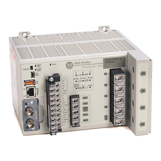
Features The PowerMonitor 5000 unit includes a number of hardware features that are common to all models. Rockwell Automation Publication 1426-UM001J-EN-P - August 2019... - Page 11 The USB device port is a USB Mini-B receptacle that accepts standard USB Mini-B plugs, for connection to a host device, such as a notebook computer. 5. Configuration Lock switch When enabled, this switch helps prevent changes in configuration that can affect revenue accuracy. Rockwell Automation Publication 1426-UM001J-EN-P - August 2019...
- Page 12 • Use current transformers (CTs) to connect to power system 12.Virtual wiring correction indicator Indicates that a virtual wiring correction command has been applied to resolve wiring errors without rewiring. Wiring Correction on page Rockwell Automation Publication 1426-UM001J-EN-P - August 2019...
- Page 13 Time of use log • • • Event log • • • Setpoint log • • • Alarm log • • • Power Quality log • • Waveform log • • Trigger Data log • • Rockwell Automation Publication 1426-UM001J-EN-P - August 2019...
-
Page 14: Before You Begin
You must already be familiar with AC power and power metering. Product Disposal At the end of its life, this equipment must be collected separately from any unsorted municipal waste. Rockwell Automation Publication 1426-UM001J-EN-P - August 2019... -
Page 15: Mounting Considerations
Mount the enclosure in a position that allows full access to the unit. Install the unit with the ventilation slots in the bottom and top of the unit unobstructed to assure adequate free convection air flow to cool the internal electronic components. Rockwell Automation Publication 1426-UM001J-EN-P - August 2019... - Page 16 4 . 88 4 . 65 ---- Z R1 O ---- R1 com R1 C ---- R2 O R2 com ---- R2 C R3 O ---- R3 com R3 C 3 .3 0 . 13 Rockwell Automation Publication 1426-UM001J-EN-P - August 2019...
- Page 17 5. Connect the ground bus to a functional earth ground on the panel. IMPORTANT The upper mounting slots are equipped with protective conductor terminals that must make metal-to-metal contact with the grounded mounting panel. Rockwell Automation Publication 1426-UM001J-EN-P - August 2019...
-
Page 18: Wire The Powermonitor 5000 Unit
Connect a 2.5 mm (14 AWG) wire from the GND terminal of the PowerMonitor 5000 unit to the ground bus or other low-impedance earth ground before you connect the control power or any other connections. Rockwell Automation Publication 1426-UM001J-EN-P - August 2019... - Page 19 • Three10 A fuses and blocks voltage sensing wiring protection • One 1 A fuse and block for control wiring protection • One 8-pole shorting terminal block for CT wiring Contact your local Allen-Bradley distributor or Rockwell Automation sales representative for more information. Voltage and Current Sensing Connections The PowerMonitor 5000 unit can monitor various three-phase, single-phase, and split-phase circuits.
- Page 20 PowerMonitor 5000 unit in parallel with the voltage sensing terminals of the existing metering devices. The following wiring diagrams indicate typical voltage sensing connections to various types of power systems. Rockwell Automation Publication 1426-UM001J-EN-P - August 2019...
- Page 21 Figure 5 - Diagram V2 - 3-phase, 3-wire Grounded Wye, or 3-phase, 3-wire Delta (690V AC Line-to- line Maximum) Metering_Mode = Wye, Line Delta 2 CT or Delta 3 CT, as applicable PowerMonitor 5000 Fuses (by user) Load Ground Rockwell Automation Publication 1426-UM001J-EN-P - August 2019...
- Page 22 (1) Fuse in neutral connection is required for impedance grounded systems. Figure 7 - Diagram V4 - 3-phase, 4-wire Impedance Grounded Wye with Line and Neutral PTs Line Metering_Mode = Wye PowerMonitor 5000 Fuses (by user) PTs (by user) Ground Load Ground Ground Rockwell Automation Publication 1426-UM001J-EN-P - August 2019...
- Page 23 132. If the voltage rotation is reported as 132, it is recommended to swap V1 and V3. Then, rerun wiring diagnostics to determine if additional changes are necessary. Rockwell Automation Publication 1426-UM001J-EN-P - August 2019...
- Page 24 Metering_Mode = Split-phase PowerMonitor 5000 Fuses (by user) Load Ground Figure 11 - Diagram V8 - Split-phase with PTs Line Metering_Mode = Split-phase PowerMonitor 5000 Fuses (by user) PTs (by user) Ground Ground Load Rockwell Automation Publication 1426-UM001J-EN-P - August 2019...
- Page 25 Figure 13 - Diagram V10 - 3-phase, 4-wire High Leg Delta (690V AC Line-to-line Maximum) High-leg Transformer (by user) Metering_Mode = Delta High-leg PowerMonitor 5000 Fuses (by user) Load Ground Rockwell Automation Publication 1426-UM001J-EN-P - August 2019...
- Page 26 Voltage Mode = Single-phase PowerMonitor 5000 Fuses (by user) Load Ground Figure 15 - Diagram V12 - Single-phase with PTs Line Voltage Mode = Single-phase PowerMonitor 5000 Fuses (by user) PTs (by user) Ground Load Rockwell Automation Publication 1426-UM001J-EN-P - August 2019...
- Page 27 CT secondary and current sensing circuits of the existing metering devices. Do not install overcurrent protection or non-shorting disconnecting means in CT secondary wiring. Connect the current sensing circuit to a low-impedance earth ground at only one point. Rockwell Automation Publication 1426-UM001J-EN-P - August 2019...
- Page 28 Metering_Mode = Delta 2 CT, Open Delta 2 CT, Line or Delta Grd B Ph 2 CT, as applicable Shorting Terminal PowerMonitor 5000 Block (by user) CTs (by user) 2 CTs Can Be Used Only On 3-wire Systems Load Ground Rockwell Automation Publication 1426-UM001J-EN-P - August 2019...
- Page 29 CTs (by user) used) Load Ground Figure 19 - Diagram I4 - Single Phase, 1 CT Voltage Mode = Single-phase Line Shorting Terminal PowerMonitor 5000 Block (by user) CT (by user) Ground Load Rockwell Automation Publication 1426-UM001J-EN-P - August 2019...
- Page 30 (by user) Rn com (COM) Rn O (N.O.) ( + ) ( - ) PowerMonitor 5000 Wetting Power (typical for R1, R2, and R3) Supply Controlled Load Max 240V AC/DC (by user) (by user) Rockwell Automation Publication 1426-UM001J-EN-P - August 2019...
-
Page 31: Connect Communication
TIP You can also display the PowerMonitor 5000 web interface by using a PanelView™ Plus 6 terminal with a 2711P-RP9_ logic module with extended features. USB communication drivers are already installed in the logic module. Configure the Connection on page 41 to continue the setup. Rockwell Automation Publication 1426-UM001J-EN-P - August 2019... - Page 32 Install the PowerMonitor 5000 Unit Download the USB Driver To download the USB driver, follow these steps. 1. Navigate to http://compatibility.rockwellautomation.com/Pages/ MultiProductDownload.aspx?crumb=112 and click sign in. 2. Enter your Email Address, Password, and click Sign In. Rockwell Automation Publication 1426-UM001J-EN-P - August 2019...
- Page 33 Install the PowerMonitor 5000 Unit Chapter 2 3. Enter 1426 in the Product Search window. 4. Select PowerMonitor 5000 USB Driver and Installation Instructions and then click Downloads. 5. Click Select Files. Rockwell Automation Publication 1426-UM001J-EN-P - August 2019...
- Page 34 Install the PowerMonitor 5000 Unit 6. Select PowerMonitor 5000 USB driver/instruct (a) and click Download Cart (b). 7. Click Download Now. 8. Read the End-User Software Agreement and click Accept. 9. Click Managed Download. Rockwell Automation Publication 1426-UM001J-EN-P - August 2019...
- Page 35 12. In the Windows Explorer window that opens, navigate to 1426-Products > RAFirmware > 1426-Products > Test > 1426-M5E-xxx- PM5000_USB_Driver_Install. The full path to access the file is: Downloads > RA > 1426-Products > RAFirmware > 1426-Products > Test > 1426-M5E-xxx-PM5000_USB_Driver_Install. Rockwell Automation Publication 1426-UM001J-EN-P - August 2019...
- Page 36 Install the PowerMonitor 5000 Unit 13. Right-click on the zipped folder and extract the files. 14. Right-click on zipped folder RNDIS_01.zip and extract files. 15. Close the Rockwell Automation® Download Manager and sign out of RockwellAutomation.com. Install Drivers To install the USB driver, follow these steps.
- Page 37 Install the PowerMonitor 5000 Unit Chapter 2 3. Click Device Manager to open. 4. In Device Manager, open Other devices. Rockwell Automation Publication 1426-UM001J-EN-P - August 2019...
- Page 38 Chapter 2 Install the PowerMonitor 5000 Unit 5. Right-click RNDIS Serial and select Update Driver Software. 6. Select Browse my computer for driver software. Rockwell Automation Publication 1426-UM001J-EN-P - August 2019...
- Page 39 7. Click Browse and navigate to the RNDIS Driver INF folder and click OK. The full path to access the file is: Downloads > RA > 1426-Products > RAFirmware > 1426-Products > Test > 1426-M5E-xxx-PM5000_USB_Driver_Install > RNDIS > RNDIS Driver INF. 8. Click Next. Rockwell Automation Publication 1426-UM001J-EN-P - August 2019...
- Page 40 Chapter 2 Install the PowerMonitor 5000 Unit 9. If a windows security window pops up, click ‘Install this driver software anyway’ . 10. When the driver successfully installs, click Close. Rockwell Automation Publication 1426-UM001J-EN-P - August 2019...
- Page 41 2. Click Change adapter settings. 3. Verify that the PowerMonitor 5000 unit is connected to the personal computer by using the USB cable. 4. Double-click Local Area Connection that is associated with the Remote NDIS-based Device. Rockwell Automation Publication 1426-UM001J-EN-P - August 2019...
- Page 42 The default subnet mask 255.255.255.0 is correct. Note: The default IP address of the PowerMonitor 5000 unit is 192.168.169.3. 8. Then, click OK. Your connection has now been configured and you can browse the PowerMonitor 5000 web page by using the USB connection. Rockwell Automation Publication 1426-UM001J-EN-P - August 2019...
- Page 43 By default the security setting of the power monitor web page is disabled. 2. To enable security, see Configure Initial Security on page 56 for more information. Rockwell Automation Publication 1426-UM001J-EN-P - August 2019...
- Page 44 R1 C R1 C ---- R2 O ---- R2 O R2 com R2 com ---- R2 C ---- R2 C R3 O R3 O ---- R3 com ---- R3 com R3 C R3 C Rockwell Automation Publication 1426-UM001J-EN-P - August 2019...
- Page 45 Signal Function Color VDC+ (V+) Power Supply CAN_H Signal High White SHIELD Shield Uninsulated CAN_L Signal Low Blue COM (V-) Common Black IMPORTANT Terminal numbers are listed as they appear on the connector. Rockwell Automation Publication 1426-UM001J-EN-P - August 2019...
- Page 46 SLC™ Controller With equipped with internal 1747-SDN Scanner terminating resistors. CAN_H SHLD Terminating CAN_L Resistor (see Note 2) Or Other DeviceNet Scanner Devices DeviceNet 24V DC Power Supply Rockwell Automation Publication 1426-UM001J-EN-P - August 2019...
- Page 47 24 VDC Scom ---- S com S com ---- K ---- Z R1 O ---- R1 com R1 C ---- R2 O R2 com ---- R2 C R3 O ---- R3 com R3 C Rockwell Automation Publication 1426-UM001J-EN-P - August 2019...
- Page 48 Chapter 2 Install the PowerMonitor 5000 Unit Notes: Rockwell Automation Publication 1426-UM001J-EN-P - August 2019...
-
Page 49: Setup Using The Web Interface
USB cable. See USB Communication on page Interface Initial setup is performed by using the USB web interface and initial security setup can be performed only by using the USB web interface. Rockwell Automation Publication 1426-UM001J-EN-P - August 2019... - Page 50 • Date and Time - this feature sets the unit internal clock so that time stamps in logged data are correct • Security (if desired) - enable and configure security to guard against unauthorized changes to the power monitor configuration Rockwell Automation Publication 1426-UM001J-EN-P - August 2019...
- Page 51 USB administrator login from the network. You remain logged in until you log out or until 30 minutes have passed since configuration changes have been applied. Rockwell Automation Publication 1426-UM001J-EN-P - August 2019...
- Page 52 2. To change the basic metering setup, enter the desired values into the text boxes, scroll down, and click Apply Changes. A dialog box appears to report the result of the setup change. Rockwell Automation Publication 1426-UM001J-EN-P - August 2019...
- Page 53 Another option can be to configure the power monitor as a reserved client in the DHCP server. Refer to Communication on page 219 for more information on communication setup parameters. Rockwell Automation Publication 1426-UM001J-EN-P - August 2019...
- Page 54 IMPORTANT You can change the network configuration from the USB or network web pages. If you change the IP address from the network web interface, browse to the new IP address to re-establish communication. Rockwell Automation Publication 1426-UM001J-EN-P - August 2019...
- Page 55 2. Enter the year, month, day, hour, and minute into the corresponding input fields and click Apply Changes. If your power monitor is configured for time synchronization with either an SNTP or IEEE 1588 PTP server, the time is already set. Rockwell Automation Publication 1426-UM001J-EN-P - August 2019...
- Page 56 4. Log in with user name usbadmin and password usbadmin. 5. Accept the prompt that the login was successful. 6. To add a network administrator, click AddNew. Rockwell Automation Publication 1426-UM001J-EN-P - August 2019...
- Page 57 1. Browse to the network address of the PowerMonitor 5000 unit. 2. Click Log in from the page header and enter the user name and password that is created and click Log In. Rockwell Automation Publication 1426-UM001J-EN-P - August 2019...
-
Page 58: Commands
If security is enabled, a logged-in Administrator class user can initiate commands by using the web page; or a logged-in Application class user can initiate commands by using optional software or communication. Rockwell Automation Publication 1426-UM001J-EN-P - August 2019... -
Page 59: Setup Using Custom Add-On Profile
Explicit Messaging, or other means. The Module Properties dialog box does NOT display subcategories specific to the device configuration. Additionally, the connection type does not contain a configuration instance. This option effectively disables Automatic Device Configuration. Rockwell Automation Publication 1426-UM001J-EN-P - August 2019... - Page 60 PowerMonitor 5000 unit in a new Logix project offline. An offline configured PowerMonitor 5000 unit can be quickly copied and pasted to configure multiple PowerMonitor 5000 units. 1. Open the Logix Designer application. 2. From the File menu, choose New. Rockwell Automation Publication 1426-UM001J-EN-P - August 2019...
- Page 61 3. Select the controller type and set the project name and location. 4. Click Next. 5. Select the controller information and click Finish. 6. Under the I/O Configuration tree, right-click the 1756 Backplane, and choose New Module. The Select Module Type dialog box appears. Rockwell Automation Publication 1426-UM001J-EN-P - August 2019...
- Page 62 The New Module configuration dialog box appears. 8. Configure the Ethernet communication module, and click OK. 9. In the I/O Configuration folder, right-click Ethernet and choose New Module. The Select Module Type dialog box appears. Rockwell Automation Publication 1426-UM001J-EN-P - August 2019...
- Page 63 The name creates tags in RSLogix 5000 or Studio 5000 software that can be used to read and write data from the PowerMonitor 5000 module. 12. In the Module Definition section, click Change. The Module Definition dialog box appears. Rockwell Automation Publication 1426-UM001J-EN-P - August 2019...
- Page 64 In this example, the Connection and Configured By fields are left at the default selections of Data and This Controller. 14. To save and close the Module Definition dialog box, click OK. 15. If prompted, click Yes to change the module definition. Rockwell Automation Publication 1426-UM001J-EN-P - August 2019...
- Page 65 Evaluate the system and application and determine the appropriate configuration settings, select the applicable configuration page from the navigation tree, and use the configuration pages to enter the settings. Rockwell Automation Publication 1426-UM001J-EN-P - August 2019...
- Page 66 You must be sure that the entry is reasonable for the specific application. If you enter an out-of-range parameter in a Configuration tab, a message box reports the error and the appropriate limits. Rockwell Automation Publication 1426-UM001J-EN-P - August 2019...
- Page 67 • Metering Configuration Page - The Metering Configuration page is used to configure the parameters that are related to metering and demand. Rockwell Automation Publication 1426-UM001J-EN-P - August 2019...
- Page 68 • Input Configuration Page - The Input Configuration page is used to configure the parameters that are related to the operation of the status inputs, KYZ output, and relay outputs. Rockwell Automation Publication 1426-UM001J-EN-P - August 2019...
-
Page 69: Setup Using Optional Software
FactoryTalk EnergyMetrix User Manual, publication FTEM-UM003, or online help topics for information on configuring the PowerMonitor 5000 unit by using FactoryTalk EnergyMetrix software. Contact your local Rockwell Automation sales office or Allen-Bradley distributor, or visit http://www.software.rockwell.com for more information on available software packages. - Page 70 Chapter 3 Setup and Commands Notes: Rockwell Automation Publication 1426-UM001J-EN-P - August 2019...
-
Page 71: Basic Metering
These basic metering parameters are listed in the table that follows. The basic metering setup is necessary to obtain accurate, properly scaled metering results. Basic metering applies to all models of the PowerMonitor 5000 unit. Rockwell Automation Publication 1426-UM001J-EN-P - August 2019... - Page 72 I4_CT_Primary These parameters define the transformation ratios of the current transformers (CTs) used to connect the power monitor to the measured power circuit. The secondary value is permitted to be only 5 A. Rockwell Automation Publication 1426-UM001J-EN-P - August 2019...
-
Page 73: Wiring Diagnostics
5% of the nominal metering scale, or 250 mA of CT secondary current. For example, a power monitor with 600:5 CT ratios that are configured for I1, I2, and I3 requires 30 amps of load current for wiring diagnostics to operate. Rockwell Automation Publication 1426-UM001J-EN-P - August 2019... - Page 74 In addition to wiring diagnostics on command, the PowerMonitor 5000 unit updates voltage and current magnitude and phase angle data continually. These values are used by FactoryTalk® EnergyMetrix™ RT software to display a system phasor diagram. Rockwell Automation Publication 1426-UM001J-EN-P - August 2019...
- Page 75 Results are available for about 30 minutes after the command is received. Command_Status Values 0 = Command Active 1 = Input Level Low 2 = Disabled 3 = Waiting Command Rockwell Automation Publication 1426-UM001J-EN-P - August 2019...
- Page 76 Example: 213 = Phase 2 then phase 1 then phase 3 -1 = Test not run 4 = Invalid Rotation 5 = Out of range Phasor Magnitudes and Angles The PowerMonitor 5000 unit updates these values continually. Rockwell Automation Publication 1426-UM001J-EN-P - August 2019...
- Page 77 Current angles in Delta modes include a 30° offset due to the phase angle difference between Wye and Delta modes as shown in the following diagram. Related Functions • Voltage and Current Metering • Power Metering • Energy Metering Rockwell Automation Publication 1426-UM001J-EN-P - August 2019...
-
Page 78: Wiring Correction
2 = Correct wiring automatically by using Power Factor Range 2 results 3 = Correct wiring automatically by using Power Factor Range 3 results 4 = Correct wiring by using manual input-mapping parameters 5 = Remove all wiring corrections. Rockwell Automation Publication 1426-UM001J-EN-P - August 2019... - Page 79 1 = Selected range is incomplete 2 = Command is already active. Use command 5 (remove all wiring corrections) to start over 3 = Two like inputs that are wired to one terminal 4 = Invalid Input parameter Rockwell Automation Publication 1426-UM001J-EN-P - August 2019...
-
Page 80: Metering Overview
• Crest Factor • K-Factor • Phase Rotation (ABC, ACB) • Time of Use Metering Accuracy Class ANSI C12.20 -2010 (clause 8) Class 0.2 and EN 62053-22 - 2003 (clause 5.5.4) Class 0.2 Rockwell Automation Publication 1426-UM001J-EN-P - August 2019... -
Page 81: Energy Metering
Total sum of forward and reverse reactive energy ±0.000…999,999 kVARh GVAh Total apparent energy consumed 0…9,999,999 GVAh kVAh Total apparent energy consumed 0.000…999,999 kVAh Accumulated amp-hours consumed 0…9,999,999 Accumulated amp-hours consumed 0.000…999,999 Rockwell Automation Publication 1426-UM001J-EN-P - August 2019... - Page 82 345.456 GWh, the correct entry is GWh = 345 and KWh = 456. This applies to all consumption counters. Related Functions • KYZ output • Energy log • Configuration lock Rockwell Automation Publication 1426-UM001J-EN-P - August 2019...
-
Page 83: Demand Metering
The formula for real power (kW) demand is the following. × P t ( ) t d -- - Demand T = Demand interval duration T = Time at beginning of interval P(t) = Power as a function of time Rockwell Automation Publication 1426-UM001J-EN-P - August 2019... - Page 84 • Performs a first order projection of what the final demand is at the end of the interval This method can be useful where your system has a significant base load with additional loads that are switched in and out during the interval. Rockwell Automation Publication 1426-UM001J-EN-P - August 2019...
- Page 85 1…99 = Length of time of each demand period in minutes The following are the semantics: • When set to 0 there are no projected demand calculations. • If the internal timer is selected, a setting of 0 turns off the demand function. Rockwell Automation Publication 1426-UM001J-EN-P - August 2019...
- Page 86 The common port for demand broadcast messages. These values are for this parameter: 300 (default)…400 Commands Controller command (EOI signal) Related Functions • Status inputs • Time of use log • Configuration lock Rockwell Automation Publication 1426-UM001J-EN-P - August 2019...
-
Page 87: Power Metering
Lead or lag indicator for power factor -1…+1 1 = leading L2_PF_Lead_Lag_Indicator -1 = lagging L3_PF_Lead_Lag_Indicator Total_PF_Lead_Lag_Indicator Only total three-phase power results are provided when Direct Delta or Open Delta wiring modes are selected. Rockwell Automation Publication 1426-UM001J-EN-P - August 2019... - Page 88 (Power Factor Lagging) (Power Factor Leading) 270° Pf = 0 -kVAR (Export) kVARHR-R (Reverse) Setup Only basic metering setup is required for power metering. Related Functions • Metering result averaging • Configuration lock Rockwell Automation Publication 1426-UM001J-EN-P - August 2019...
-
Page 89: Voltage, Current, Frequency Metering
Delta metering modes. Line-to-neutral voltage results are not provided in Delta (other than high-leg Delta) and Open Delta metering modes. Voltage and current unbalance are calculated by using the following formula. Negative Sequence × --------------------------------------------- - Positive Sequence Rockwell Automation Publication 1426-UM001J-EN-P - August 2019... - Page 90 You can view voltage, current, frequency, energy, and power metering results from the PowerMonitor 5000 web page. Browse to the network address of the power monitor. From the home page, choose the MeteringResults folder and then the desired metering results page. Rockwell Automation Publication 1426-UM001J-EN-P - August 2019...
-
Page 91: Configuration Lock
The following setup parameters and commands are locked when the configuration lock is applied. Configuration.Metering_Basic All parameters. Configuration.SystemGeneral • KYZ and Relay Outputs setup • Status inputs scale Configuration.CommunicationsNative • Network demand setup Rockwell Automation Publication 1426-UM001J-EN-P - August 2019... - Page 92 • Clear all energy registers • Set status input count • Force relay or KYZ output on, off, or clear force • Restore factory defaults • Reset power monitor Setup No setup is needed. Rockwell Automation Publication 1426-UM001J-EN-P - August 2019...
- Page 93 • Range of valid values • Default values • Data type Set-up parameters can be found in data tables with names beginning with ‘Configuration’ , for instance Configuration.Metering_Basic. Rockwell Automation Publication 1426-UM001J-EN-P - August 2019...
-
Page 94: Chapter 5
IEEE Current THD % • • • • • IEC Voltage THD % • • • • • IEC Current THD % • • • • • Crest Factor, Voltage, and Current • • • • Rockwell Automation Publication 1426-UM001J-EN-P - August 2019... -
Page 95: Chapter 5
EN61000-4-30 data flagging • • EN61000-4-30 supply voltage inbalance • • EN61000-4-30 time aggregation • • • EN61000-4-30 Mains signaling voltage on the supply voltage • • EN61000-4-30 rapid voltage changes • • Rockwell Automation Publication 1426-UM001J-EN-P - August 2019... -
Page 96: Harmonic Analysis
This measurement can also be used to express the dynamic range of a measurement device. Crest Factor is the ratio of the peak to the RMS. ⁄ Crest Factor Peak Value RMS Value A pure sinusoid Crest Factor equals Rockwell Automation Publication 1426-UM001J-EN-P - August 2019... - Page 97 … I2_Crest_Factor 9.999E15 … I3_Crest_Factor 9.999E15 … I4_Crest_Factor 9.999E15 … V1_IEEE_THD_% 0.00 100.00 … V2_IEEE_THD_% 0.00 100.00 … V3_IEEE_THD_% 0.00 100.00 … VN_G_IEEE_THD_% 0.00 100.00 … Avg_IEEE_THD_V_% 0.00 100.00 … V1_V2_IEEE_THD_% 0.00 100.00 Rockwell Automation Publication 1426-UM001J-EN-P - August 2019...
- Page 98 DC offset is always zero for current channels. Only directly connected voltage channels return non-zero DC offset values. Angles are expressed in degrees, with zero degrees corresponding to the time stamp of the metering results. Rockwell Automation Publication 1426-UM001J-EN-P - August 2019...
- Page 99 • PowerQuality.V3_N_Volts_H2_RMS (32…63) • PowerQuality.V3_N_Volts_H3_RMS (64…95, M8 model) • PowerQuality.V3_N_Volts_H4_RMS (96…127, M8 model) • PowerQuality.VN_G_Volts_H1_RMS (DC…31) • PowerQuality.VN_G_Volts_H2_RMS (32…63) • PowerQuality.VN_G_Volts_H3_RMS (64…95, M8 model) • PowerQuality.VN_G_Volts_H4_RMS (96…127, M8 model) • PowerQuality.V1_V2_Volts_H1_RMS (DC…31) • PowerQuality.V1_V2_Volts_H2_RMS (32…63) Rockwell Automation Publication 1426-UM001J-EN-P - August 2019...
- Page 100 • PowerQuality.L2_kW_H3_RMS (64…95, M8 model) • PowerQuality.L2_kW_H4_RMS (96…127, M8 model) • PowerQuality.L3_kW_H1_RMS (DC…31) • PowerQuality.L3_kW_H2_RMS (32…63) • PowerQuality.L3_kW_H3_RMS (64…95, M8 model) • PowerQuality.L3_kW_H4_RMS (96…127, M8 model) • PowerQuality.L1_kVAR_H1_RMS (DC…31) • PowerQuality.L1_kVAR_H2_RMS (32…63) • PowerQuality.L1_kVAR_H3_RMS (64…95, M8 model) Rockwell Automation Publication 1426-UM001J-EN-P - August 2019...
- Page 101 • PowerQuality.V3_N_Volts_H4_Ang (96…127, M8 model) • PowerQuality.VN_G_Volts_H1_Ang (DC…31) • PowerQuality.VN_G_Volts_H2_Ang (32…63) • PowerQuality.VN_G_Volts_H3_Ang (64…95, M8 model) • PowerQuality.VN_G_Volts_H4_Ang (96…127, M8 model) • PowerQuality.V1_V2_Volts_H1_Ang (DC…31) • PowerQuality.V1_V2_Volts_H2_Ang (32…63) • PowerQuality.V1_V2_Volts_H3_Ang (64…95, M8 model) • PowerQuality.V1_V2_Volts_H4_Ang (96…127, M8 model) Rockwell Automation Publication 1426-UM001J-EN-P - August 2019...
-
Page 102: Sag And Swell Detection
IEEE 1159 and EN 50160 independently detect and report sags and swells. When sags or swells are detected, these models record waveforms and record detailed event information in the Power Quality Log. Rockwell Automation Publication 1426-UM001J-EN-P - August 2019... - Page 103 A swell is detected when any phase voltage exceeds a swell threshold. Sag and swell detection operate on line-to-line voltages in Delta wiring modes, and on line-to-neutral voltages in Wye and split-phase wiring modes. Rockwell Automation Publication 1426-UM001J-EN-P - August 2019...
-
Page 104: Waveform Recording (M6 And M8 Model)
• WSB_Mode - waveform synchronization broadcast mode. The options are the following: – 0 = Disable (default) – 1 = Enable • WSB_Port - specified UDP port for WSB feature, range = 1001 (default)…1009 Rockwell Automation Publication 1426-UM001J-EN-P - August 2019... - Page 105 Each type of message also contains a network id (last 3 bytes of the originator's MAC ID), trigger type (sag, swell, or user command) and timestamp information. Rockwell Automation Publication 1426-UM001J-EN-P - August 2019...
- Page 106 In the unlikely event that the PowerMonitor 5000 unit resources are overstressed so that the unit is unable to write a waveform record to non-volatile memory in a timely fashion, the in-process waveform record ends with the latest cycle that is captured in RAM. Rockwell Automation Publication 1426-UM001J-EN-P - August 2019...
- Page 107 • MicroS = the microsecond timestamp of the record, which is used for aligning WSB waveform records • HH = the UTC hour avoids duplication during daylight-saving time transition Rockwell Automation Publication 1426-UM001J-EN-P - August 2019...
- Page 108 Reading Waveform Records by Using the Data Table Interface The procedure for reading waveform records is similar to the procedure used for reading data logging records. Refer to Reading Waveform Records by Using the Data Table Interface on page 108. Rockwell Automation Publication 1426-UM001J-EN-P - August 2019...
- Page 109 Power Quality Monitoring Chapter 5 Related Functions • Sag and Swell Detection • Network Time Synchronization • Power Quality Log Application Reading waveform records applies only to the M6 and M8 models. Rockwell Automation Publication 1426-UM001J-EN-P - August 2019...
- Page 110 Chapter 5 Power Quality Monitoring Notes: Rockwell Automation Publication 1426-UM001J-EN-P - August 2019...
- Page 111 • Range of valid values • Default values • Data type Set-up parameters can be found in data tables with names beginning with ‘Configuration’ , for instance Configuration.Metering_Basic. Rockwell Automation Publication 1426-UM001J-EN-P - August 2019...
-
Page 112: Logging Overview
Energy_Log_Interval selects how often a record is logged, in minutes: 0 = Disables energy logging 1…60 = Length of logging interval in minutes -1 = Synchronizes energy logging to the end of the demand interval Rockwell Automation Publication 1426-UM001J-EN-P - August 2019... - Page 113 Load_Factor_Auto_Log_Setting defines the day of month to start a new load factor log record. PowerQuality_Log_Mode This parameter sets the action of the log once the log has filled to capacity. 0 = Stop logging 1 = Overwrite oldest record Rockwell Automation Publication 1426-UM001J-EN-P - August 2019...
- Page 114 Energy and data logs are stored in multiple files. The date and time of the first record of each file is embedded in the file name. The date and time of the most recent record each file is listed in the file creation date and time columns. Rockwell Automation Publication 1426-UM001J-EN-P - August 2019...
- Page 115 Snapshot, EN50160 Weekly, and EN50160 Yearly logs can be retrieved sequentially, one record at a time, in either forward or reverse order. The Min/ Max, Load Factor, Time-of-Use, EN50160 Weekly, and EN50160 Yearly logs also support the retrieval of individually specified records. Rockwell Automation Publication 1426-UM001J-EN-P - August 2019...
- Page 116 13 = Trigger Header File LoggingResults.TriggerData_Header (M6 and M8 model) 14 = EN50160 Weekly Log LoggingResults.EN50160_Weekly_Log (M8 only) 15 = EN50160 Yearly Log LoggingResults.EN50160_Yearly_Log (M8 only) Requests not supported by the power monitor model are ignored. Rockwell Automation Publication 1426-UM001J-EN-P - August 2019...
- Page 117 0 = Use sequential return in the order selected 1 = Retrieve the current active record 2 = Retrieve the latest closed monthly record … 13 = Retrieve the earliest closed monthly record Rockwell Automation Publication 1426-UM001J-EN-P - August 2019...
-
Page 118: Waveform Log (M6 And M8 Model)
1. Open Studio 5000® environment and select ‘New Project’ . 2. Select the controller that is connected with the PowerMonitor device, name your Logix project and click Next. Rockwell Automation Publication 1426-UM001J-EN-P - August 2019... - Page 119 5. From the New Tag dialog box, create the tag. a. Enter a tag name. b. Click the ellipse in the Data Type field. The Select Data Type dialog box opens. c. Select the data type. Rockwell Automation Publication 1426-UM001J-EN-P - August 2019...
- Page 120 To close the New Tag dialog box, click Create. Name Data Type Array Dimensions BITS DINT – Status_TableWrites Waveform_File_Name STRING Waveform_LogResults REAL ConfigurationLog_Read 6. In the Controller Tags section, set the ConfigurationLog_Read[0] value to 11 and the ConfigurationLog_Read[1] value to 1. Rockwell Automation Publication 1426-UM001J-EN-P - August 2019...
- Page 121 7. In the Controller Tags section, click Edit Tags. 8. Create five message tags with the following descriptions: Create a Program String 1. From the Controller Organizer under Main Program, double-click ‘MainRoutine’ . Rockwell Automation Publication 1426-UM001J-EN-P - August 2019...
- Page 122 • The ‘examine on’ components are named BITS 0, BITS 2, BITS 4, BITS 6, and BITS 8. • The ‘one shot’ components are named BITS 1, BITS 3, BITS 5, BITS 7, and BITS 9. Rockwell Automation Publication 1426-UM001J-EN-P - August 2019...
- Page 123 1. To communicate to the device within the I/O tree, click the ellipses on the MSG component and select Communication (1). 2. Click Browse (2), select your device module in the I/O tree (3), and click Apply. Complete this step for ALL message components. Rockwell Automation Publication 1426-UM001J-EN-P - August 2019...
- Page 124 4. For the ‘Config Log Read’ message, verify that the Service type is set to ‘Set Attribute Single’ and the Source Length set to 30. 5. Set the parameters as shown in the dialog box. Rockwell Automation Publication 1426-UM001J-EN-P - August 2019...
- Page 125 7. For the ‘Status Table Write’ message, set the service type to ‘Get Attribute Single’ and set the parameters to match the ‘Status Table Write’ Instance. 8. Set the Destination Element (1) to ‘Status_TableWrites[0]’ . Rockwell Automation Publication 1426-UM001J-EN-P - August 2019...
- Page 126 12. Set the source (3) to Waveform_File_Name[0]. 13. For the ‘Read Waveform’ message, set the Service Type (1) to ‘Get Attribute Single’ and set the parameters (2) to match the ‘LoggingReults.Waveform Log’ Instance. Rockwell Automation Publication 1426-UM001J-EN-P - August 2019...
- Page 127 MSG component and select Communication. 2. Click Browse and select your device module in the I/O tree. Complete this step for ALL message components. The PCCC method is similar to the CIP method. Rockwell Automation Publication 1426-UM001J-EN-P - August 2019...
- Page 128 Destination Element and configure the message as shown in the dialog box. 4. For the ‘Stat Tbl Write’ message, select ‘Status_TableWrites[0]’ as the Destination Element and configure the message as shown in the dialog box. Rockwell Automation Publication 1426-UM001J-EN-P - August 2019...
- Page 129 Destination Element and configure the message as shown in the dialog box. 6. For the ‘Write File Name’ message, select ‘Waveform_File_Name[0]’ as the Destination Element and configure the message as shown in the dialog box. Rockwell Automation Publication 1426-UM001J-EN-P - August 2019...
- Page 130 Destination Element and configure the message as shown in the dialog box. Driving the Main Program 1. In the toolbar at the top of the Logix Designer application, click Communications and select Who Active. Rockwell Automation Publication 1426-UM001J-EN-P - August 2019...
- Page 131 Waveform file. When all zeros (00) are returned the file is complete. This read can take some time. By toggling Rung 4 multiple times, you are selecting which waveform to retrieve. Rockwell Automation Publication 1426-UM001J-EN-P - August 2019...
- Page 132 The returned value X_(h) where X_(h) = the RMS magnitude or angle of the spectral component h. Units are Volts, Amps or degrees, depending on the value of Channel and Mag_Angle elements X_(1 + Order * 32) … … X_(31 + Order * 32) Rockwell Automation Publication 1426-UM001J-EN-P - August 2019...
- Page 133 Waveform Recording (M6 and M8 model) on page 104 for more information about waveform setup, operation, commands, related functions, and retrieval via FTP and the native Ethernet port. Rockwell Automation Publication 1426-UM001J-EN-P - August 2019...
-
Page 134: Energy Log
File Names Energy log file names have the following semantics: EnergyLog_YYYYMMDD_hhmm_HH.csv Where: • YYYYMMDD_hhmm - the file creation date and time • HH - UTC hour avoids duplication during daylight-saving time transition Rockwell Automation Publication 1426-UM001J-EN-P - August 2019... - Page 135 The average real, reactive, apparent power and power factor during the last demand period kVAR_Demand kVA_Demand Demand_PF Projected_kW_Demand The projected average real, reactive, and apparent power for the current demand period Projected_kVAR_Demand Projected_kVA_Demand Rockwell Automation Publication 1426-UM001J-EN-P - August 2019...
- Page 136 • Alternately, ‘allfiles’ , to return records from all Energy Log files • An appended chronology switch: – ‘/r’ to begin with the most recent record – ‘/f ’ to return the oldest record first (default if no chronology switch is appended) Rockwell Automation Publication 1426-UM001J-EN-P - August 2019...
- Page 137 The Energy Log requires the following to be configured: • Basic metering setup • Logging configuration • Date and Time setup Commands Clear energy log Related Functions • Energy Metering, Demand Metering • Data Log • Configuration lock Rockwell Automation Publication 1426-UM001J-EN-P - August 2019...
-
Page 138: Data Log
These parameters define the set of records that are maintained in the data log. The Configuration.Data_Log web page includes the descriptions of the default selections for each parameter, even if the selections have been changed from their default value. Rockwell Automation Publication 1426-UM001J-EN-P - August 2019... - Page 139 V3_V1_Volts Avg_VL_VL_Volts I1_Amps I2_Amps I3_Amps I4_Amps Avg_Amps Frequency_Hz L1_kW L2_kW L3_kW Total_kW L1_kVAR kVAR L2_kVAR kVAR L3_kVAR kVAR Total_kVAR kVAR L1_kVA L2_kVA L3_kVA Total_kVA L1_True_PF L2_True_PF L3_True_PF Avg_True_PF L1_Disp_PF L2_Disp_PF L3_Disp_PF Avg_Disp_PF L1_PF_Lead_Lag_Indicator Rockwell Automation Publication 1426-UM001J-EN-P - August 2019...
- Page 140 V1_V2_Crest_Factor V2_V3_Crest_Factor V3_V1_Crest_Factor I1_Crest_Factor I2_Crest_Factor I3_Crest_Factor I4_Crest_Factor V1_IEEE_THD_% V2_IEEE_THD_% V3_IEEE_THD_% VGN_IEEE_THD_% Avg_IEEE_THD_V_% V1_V2_IEEE_THD_% V2_V3_IEEE_THD_% V3_V1_IEEE_THD_% Avg_IEEE_THD_V_V_% I1_IEEE_THD_% I2_IEEE_THD_% I3_IEEE_THD_% I4_IEEE_THD_% Avg_IEEE_THD_I_% V1_IEC_THD_% V2_IEC_THD_% V3_IEC_THD_% VGN_IEC_THD_% Avg_IEC_THD_V_% V1_V2_IEC_THD_% V2_V3_IEC_THD_% V3_V1_IEC_THD_% Avg_IEC_THD_V_V_% I1_IEC_THD_% I2_IEC_THD_% I3_IEC_THD_% Rockwell Automation Publication 1426-UM001J-EN-P - August 2019...
- Page 141 Neg_Seq_Volts Zero_Seq_Volts Pos_Seq_Amps Neg_Seq_Amps Zero_Seq_Amps Voltage_Unbalance_% Current_Unbalance_% V1_N_Volts_DC_H_RMS V1_N_Volts_1st_H_RMS V1_N_Volts_2nd_H_RMS V1_N_Volts_3rd_H_RMS V1_N_Volts_4th_H_RMS V1_N_Volts_5th_H_RMS V1_N_Volts_6th_H_RMS V1_N_Volts_7th_H_RMS V1_N_Volts_8th_H_RMS V1_N_Volts_9th_H_RMS V1_N_Volts_10th_H_RMS V1_N_Volts_11th_H_RMS V1_N_Volts_12th_H_RMS V1_N_Volts_13th_H_RMS V1_N_Volts_14th_H_RMS V1_N_Volts_15th_H_RMS V1_N_Volts_16th_H_RMS V1_N_Volts_17th_H_RMS V1_N_Volts_18th_H_RMS V1_N_Volts_19th_H_RMS V1_N_Volts_20th_H_RMS V1_N_Volts_21st_H_RMS V1_N_Volts_22nd_H_RMS V1_N_Volts_23rd_H_RMS V1_N_Volts_24th_H_RMS V1_N_Volts_25th_H_RMS Rockwell Automation Publication 1426-UM001J-EN-P - August 2019...
- Page 142 V2_N_Volts_DC_H_RMS V2_N_Volts_1st_H_RMS V2_N_Volts_2nd_H_RMS V2_N_Volts_3rd_H_RMS V2_N_Volts_4th_H_RMS V2_N_Volts_5th_H_RMS V2_N_Volts_6th_H_RMS V2_N_Volts_7th_H_RMS V2_N_Volts_8th_H_RMS V2_N_Volts_9th_H_RMS V2_N_Volts_10th_H_RMS V2_N_Volts_11th_H_RMS V2_N_Volts_12th_H_RMS V2_N_Volts_13th_H_RMS V2_N_Volts_14th_H_RMS V2_N_Volts_15th_H_RMS V2_N_Volts_16th_H_RMS V2_N_Volts_17th_H_RMS V2_N_Volts_18th_H_RMS V2_N_Volts_19th_H_RMS V2_N_Volts_20th_H_RMS V2_N_Volts_21st_H_RMS V2_N_Volts_22nd_H_RMS V2_N_Volts_23rd_H_RMS V2_N_Volts_24th_H_RMS V2_N_Volts_25th_H_RMS V2_N_Volts_26th_H_RMS V2_N_Volts_27th_H_RMS V2_N_Volts_28th_H_RMS V2_N_Volts_29th_H_RMS V2_N_Volts_30th_H_RMS V2_N_Volts_31st_H_RMS V3_N_Volts_DC_H_RMS Rockwell Automation Publication 1426-UM001J-EN-P - August 2019...
- Page 143 Units Number V3_N_Volts_1st_H_RMS V3_N_Volts_2nd_H_RMS V3_N_Volts_3rd_H_RMS V3_N_Volts_4th_H_RMS V3_N_Volts_5th_H_RMS V3_N_Volts_6th_H_RMS V3_N_Volts_7th_H_RMS V3_N_Volts_8th_H_RMS V3_N_Volts_9th_H_RMS V3_N_Volts_10th_H_RMS V3_N_Volts_11th_H_RMS V3_N_Volts_12th_H_RMS V3_N_Volts_13th_H_RMS V3_N_Volts_14th_H_RMS V3_N_Volts_15th_H_RMS V3_N_Volts_16th_H_RMS V3_N_Volts_17th_H_RMS V3_N_Volts_18th_H_RMS V3_N_Volts_19th_H_RMS V3_N_Volts_20th_H_RMS V3_N_Volts_21st_H_RMS V3_N_Volts_22nd_H_RMS V3_N_Volts_23rd_H_RMS V3_N_Volts_24th_H_RMS V3_N_Volts_25th_H_RMS V3_N_Volts_26th_H_RMS V3_N_Volts_27th_H_RMS V3_N_Volts_28th_H_RMS V3_N_Volts_29th_H_RMS V3_N_Volts_30th_H_RMS V3_N_Volts_31st_H_RMS Rockwell Automation Publication 1426-UM001J-EN-P - August 2019...
- Page 144 File Names Data log file names have the following semantics: DataLog_YYYYMMDD_hhmm_HH.csv, where: • YYYYMMDD_hhmm - the file creation date and time • HH - UTC hour avoids duplication during daylight-saving time transition Rockwell Automation Publication 1426-UM001J-EN-P - August 2019...
- Page 145 DataLog_Parameter_3 (Avg_Amps) DataLog_Parameter_4 (Frequency_Hz) DataLog_Parameter_5 (Total_kW) DataLog_Parameter_6 (Total_kVAR) DataLog_Parameter_7 (Total_kVA) DataLog_Parameter_8 (Total_PF_Lead_Lag_Indicator) DataLog_Parameter_9 (Avg_True_PF) DataLog_Parameter_10 (Avg_Disp_PF) DataLog_Parameter_11 (Avg_IEEE_THD_V_%) DataLog_Parameter_12 (Avg_IEEE_THD_V_V_%) DataLog_Parameter_13 (Avg_IEEE_THD_I_%) DataLog_Parameter_14 (Avg_IEC_THD_V_%) DataLog_Parameter_15 (Avg_IEC_THD_V_V_%) DataLog_Parameter_16 (Avg_IEC_THD_I_%) DataLog_Parameter_17 (Voltage_Unbalance_%) DataLog_Parameter_18 (Current_Unbalance_%) DataLog_Parameter_19 DataLog_Parameter_20 Rockwell Automation Publication 1426-UM001J-EN-P - August 2019...
- Page 146 LoggingResults.DataLog_FileName table returns a string containing the requested file name. The file name contains the starting date and time of the log file, as described in File Names on page 144 Rockwell Automation Publication 1426-UM001J-EN-P - August 2019...
- Page 147 Parameter index values are associated with parameter tag names as listed in the Data Log Parameter List on page 139. Commands Clear data log Related Functions • Voltage, current, frequency, power metering • Data log • Configuration lock Rockwell Automation Publication 1426-UM001J-EN-P - August 2019...
-
Page 148: Min/Max Log
The year at which this MAX record was logged. Timestamp_MAX_Mth_Day The month and day this MAX record was logged. Timestamp_MAX_Hr_Min The hour and minute this MAX record was logged. Timestamp_MAX_Sec_ms The seconds and milliseconds this MAX record was logged. Rockwell Automation Publication 1426-UM001J-EN-P - August 2019... - Page 149 V3_V1_Volts Avg_VL_VL_Volts I1_Amps I2_Amps I3_Amps I4_Amps Avg_Amps Frequency_Hz L1_kW L2_kW L3_kW Total_kW L1_kVAR kVAR L2_kVAR kVAR L3_kVAR kVAR Total_kVAR kVAR L1_kVA L2_kVA L3_kVA Total_kVA L1_True_PF_Leading L2_True_PF_Leading L3_True_PF_Leading Avg_True_PF_Leading L1_True_PF_Lagging L2_True_PF_Lagging L3_True_PF_Lagging Avg_True_PF_Lagging L1_Disp_PF Rockwell Automation Publication 1426-UM001J-EN-P - August 2019...
- Page 150 I1_Crest_Factor I2_Crest_Factor I3_Crest_Factor I4_Crest_Factor V1_IEEE_THD_% V2_IEEE_THD_% V3_IEEE_THD_% VGN_IEEE_THD_% Avg_IEEE_THD_V_% I1_IEEE_THD_% I2_IEEE_THD_% I3_IEEE_THD_% I4_IEEE_THD_% Avg_IEEE_THD_I_% V1_IEC_THD_% V2_IEC_THD_% V3_IEC_THD_% VGN_IEC_THD_% Avg_IEC_THD_V_% I1_IEC_THD_% I2_IEC_THD_% I3_IEC_THD_% I4_IEC_THD_% Avg_IEC_THD_I_% I1_K_Factor I2_K_Factor I3_K_Factor Pos_Seq_Volts Neg_Seq_Volts Zero_Seq_Volts Pos_Seq_Amps Neg_Seq_Amps Zero_Seq_Amps Rockwell Automation Publication 1426-UM001J-EN-P - August 2019...
- Page 151 200mS_VN_G_Magnitude 200mS_VN_Ave_Magnitude 200mS_V1_V2_Magnitude 200mS_V2_V3_Magnitude 200mS_V3_V1_Magnitude 200mS_VV_Ave_Magnitude 200mS_I1_Amps_Magnitude 200mS_I2_Amps_Magnitude 200mS_I3_Amps_Magnitude 200mS_I4_Amps_Magnitude 200mS_Amps_Ave_Magnitude 200mS_L1_kW 200mS_L2_kW 200mS_L3_kW 200mS_Total_kW 200mS_L1_kVAR kVAR 200mS_L2_kVAR kVAR 200mS_L3_kVAR kVAR 200mS_Total_kVAR kVAR 200mS_L1_kVA 200mS_L2_kVA 200mS_L3_kVA 200mS_Total_kVA 200mS_L1_True_PF 200mS_L2_True_PF 200mS_L3_True_PF 200mS_Total_True_PF 200mS_L1_Disp_PF 200mS_L2_Disp_PF Rockwell Automation Publication 1426-UM001J-EN-P - August 2019...
- Page 152 200mS_Avg_IEEE_THD_V_% 200mS_V1_V2_IEEE_THD_% 200mS_V2_V3_IEEE_THD_% 200mS_V3_V1_IEEE_THD_% 200mS_Avg_IEEE_THD_V_V_% 200mS_I1_IEEE_THD_% 200mS_I2_IEEE_THD_% 200mS_I3_IEEE_THD_% 200mS_I4_IEEE_THD_% 200mS_Avg_IEEE_THD_I_% 200mS_V1_N_IEC_THD_% 200mS_V2_N_IEC_THD_% 200mS_V3_N_IEC_THD_% 200mS_VN_G_IEC_THD_% 200mS_Avg_IEC_THD_V_% 200mS_V1_V2_IEC_THD_% 200mS_V2_V3_IEC_THD_% 200mS_V3_V1_IEC_THD_% 200mS_Avg_IEC_THD_V_V_% 200mS_I1_IEC_THD_% 200mS_I2_IEC_THD_% 200mS_I3_IEC_THD_% 200mS_I4_IEC_THD_% 200mS_Avg_IEC_THD_I_% 200mS_V1_N_THDS 200mS_V2_N_THDS 200mS_V3_N_THDS 200mS_VN_G_THDS 200mS_AVE_VN_THDS 200mS_V1_V2_THDS 200mS_V2_V3_THDS 200mS_V3_V1_THDS 200mS_AVE_LL_THDS Rockwell Automation Publication 1426-UM001J-EN-P - August 2019...
- Page 153 200mS_V2_V3_TIHDS 200mS_V3_V1_TIHDS 200mS_AVE_LL_TIHDS 200mS_I1_K_Factor 200mS_I2_K_Factor 200mS_I3_K_Factor 200mS_Pos_Seq_Volts 200mS_Neg_Seq_Volts 200mS_Zero_Seq_Volts 200mS_Pos_Seq_Amps 200mS_Neg_Seq_Amps 200mS_Zero_Seq_Amps 200mS_Voltage_Unbalance_% 200mS_Current_Unbalance_% 10s_Power_Frequency 3s_V1_N_Magnitude 10m_V1_N_Magnitude 2h_V1_N_Magnitude 3s_V2_N_Magnitude 10m_V2_N_Magnitude 2h_V2_N_Magnitude 3s_V3_N_Magnitude 10m_V3_N_Magnitude 2h_V3_N_Magnitude 3s_VN_G_Magnitude 10m_VN_G_Magnitude 2h_VN_G_Magnitude 3s_V1_V2_Magnitude 10m_V1_V2_Magnitude 2h_V1_V2_Magnitude 3s_V2_V3_Magnitude 10m_V2_V3_Magnitude 2h_V2_V3_Magnitude Rockwell Automation Publication 1426-UM001J-EN-P - August 2019...
- Page 154 • Date and Time setup Commands • Clear single min/max log record • Clear min/max log Related Functions • Demand metering • Voltage, current, and frequency metering • Power metering • Configuration lock Rockwell Automation Publication 1426-UM001J-EN-P - August 2019...
-
Page 155: Load Factor Log
Each record is a structure of REAL elements containing the following parameters: • LoadFactor_Record_Number • LoadFactor_End_Date • LoadFactor_Elapsed_Time • Peak_Demand _kW • Average_Demand_kW • LoadFactor_kW • Peak_Demand_kVAR • Average_Demand_kVAR • LoadFactor_kVAR • Peak_Demand_kVA • Average_Demand_kVA • LoadFactor_kVA Rockwell Automation Publication 1426-UM001J-EN-P - August 2019... -
Page 156: Time-Of-Use (Tou) Log
FTP server. The power monitor generates the log file at the time of the request. Records can also be retrieved individually or sequentially by using the data table interface. File Name The log file is named Time_of_Use_Log.csv. Rockwell Automation Publication 1426-UM001J-EN-P - August 2019... - Page 157 • Off_Peak_kVAR_Demand • Mid_Peak_GVARh_Net • Mid_Peak_kVARh_Net • Mid_Peak_kVAR_Demand • On_Peak_GVARh_Net • On_Peak_kVARh_Net • On_Peak_kVAR_Demand • Off_Peak _GVAh_Net • Off_Peak_kVAh_Net • Off_Peak_kVA_Demand • Mid_Peak_GVAh_Net • Mid_Peak_kVAh_Net • Mid_Peak_kVA_Demand • On_Peak_GVAh_Net • On_Peak_kVAh_Net • On_Peak_kVA_Demand Rockwell Automation Publication 1426-UM001J-EN-P - August 2019...
- Page 158 • Basic metering setup (including Demand) • Logging configuration • Date and Time setup Commands • Store and clear current TOU Record • Clear TOU Log Related Functions • Energy metering • Demand metering • Configuration lock Rockwell Automation Publication 1426-UM001J-EN-P - August 2019...
-
Page 159: Event Log
The seconds and milliseconds when the record was recorded. Event Type Indicates the type of event that has occurred. General Code Indicates general information about the status event. Information Code Indicates specific information about the status event. Rockwell Automation Publication 1426-UM001J-EN-P - August 2019... - Page 160 NAND Flash Memory Read/Write Failed FRAM Failed Read/Write Test Real Time Clock Real Time Clock Failed Real Time Clock not Set Watchdog Timer Watchdog Time Out Ethernet communication Ethernet Communication Port Failed SNTP_Task_init_failed Demand_Broadcast_task_ init_failed Rockwell Automation Publication 1426-UM001J-EN-P - August 2019...
- Page 161 Relay 1 Forced Off Relay 2 Forced On Relay 2 Forced Off Relay 3 Forced On Relay 3 Forced Off Status Input Activated Status Input 1 Status Input 2 Status Input 3 Status Input 4 Rockwell Automation Publication 1426-UM001J-EN-P - August 2019...
- Page 162 Status Input 3 Register Status Input 4 Register Device Power Up Device Power Down Missed External Demand Sync Register Set Clear 1024 Setup Logging configuration. Commands None. Related Functions Log status input changes. Rockwell Automation Publication 1426-UM001J-EN-P - August 2019...
-
Page 163: Setpoint Log
Test Condition. Evaluation_Type Evaluation type for setpoint. Threshold_Setting The threshold setting magnitude or percent. Hysteresis_Setting Magnitude or percent. Assert_Delay Time delay before actuation. Deassert_Delay Time delay before deassert. Output_Source Output flag or bit. Rockwell Automation Publication 1426-UM001J-EN-P - August 2019... - Page 164 • Setpoints 16…20 configuration • Setpoint Logic configuration • Setpoint Outputs configuration • Date and Time setup • Logging configuration Commands • Clear Setpoint Log • Clear Setpoint Accumulators Related Functions Setpoint configuration and operation. Rockwell Automation Publication 1426-UM001J-EN-P - August 2019...
-
Page 165: Alarm Log
The hour and minute when the record was recorded. Alarm_Timestamp_Sec_ms The seconds and milliseconds when the record was recorded. Alarm Type Indicates the type of event that has occurred. Alarm Code Indicates information about the alarm. Rockwell Automation Publication 1426-UM001J-EN-P - August 2019... - Page 166 Voltage_Over_Range_Indication Ampere_Over_Range_Indication Wiring_Diagnostics_Active Over_Range_Information V1G_Over_Range V2G_Over_Range V3G_Over_Range VNG_Over_Range I1_Over_Range I2_Over_Range I3_Over_Range I4_Over_Range PowerQuality_Status Sag_Indication_Detected Swell_Indication_Detected Transient_Indication 200mS_Sag_Swell_Status_Flag 3s_Sag_Swell_Status_Flag 10m_Sag_Swell_Status_Flag 2h_Sag_Swell_Status_Flag Logs_Status Data_Log_Full_Fill_And_Stop Event_Log_Full_Fill_And_Stop Setpoint_Log_Full_Fill_And_Stop PowerQuality_Log_Full_Fill_And_Stop Energy_Log_Full_Fill_And_Stop Waveform_Full TriggerData_Full_Fill_And_Stop Output_Pulse_Overrun KYZ_Pulse_Overrun Relay1_Pulse_Overrun Relay2_Pulse_Overrun Relay3_Pulse_Overrun Rockwell Automation Publication 1426-UM001J-EN-P - August 2019...
- Page 167 IEEE1159_DCOffset_THD_Frequency_Condition 64 IEEE1159_DCOffset_Condition_V1 IEEE1159_DCOffset_Condition_V2 IEEE1159_DCOffset_Condition_V3 IEEE1159_Voltage_THD_Condition_V1 IEEE1159_Voltage_THD_Condition_V2 IEEE1159_Voltage_THD_Condition_V3 IEEE1159_Current_THD_Condition_ I1 IEEE1159_Current_THD_Condition_ I2 IEEE1159_Current_THD_Condition_ I3 IEEE1159_PowerFrequency_Condition IEEE1159_Current_THD_Condition_ I4 1024 IEEE1159_TID_Condition IEEE1159_Voltage_TID_Condition_V1 IEEE1159_Voltage_TID_Condition_V2 IEEE1159_Voltage_TID_Condition_V3 IEEE1159_Current_TID_Condition_I1 IEEE1159_Current_TID_Condition_ I2 IEEE1159_Current_TID_Condition_ I3 IEEE1159_Current_TID_Condition_ I4 IEEE519_Overall_Status ShortTerm_TDD_THD_PASS_FAIL LongTerm_TDD_THD_PASS_FAIL ShortTerm_Individual_Harmonic_PASS_FAIL LongTerm_Individual_Harmonic_PASS_FAIL Rockwell Automation Publication 1426-UM001J-EN-P - August 2019...
- Page 168 32768 ShortTerm_18th_To_33rd_Harmonic_Status 18th_Harmonic_PASS_FAIL 19th_Harmonic_PASS_FAIL 20th_Harmonic_PASS_FAIL 21st_Harmonic_PASS_FAIL 22nd_Harmonic_PASS_FAIL 23rd_Harmonic_PASS_FAIL 24th_Harmonic_PASS_FAIL 25th_Harmonic_PASS_FAIL 26th_Harmonic_PASS_FAIL 27th_Harmonic_PASS_FAIL 28th_Harmonic_PASS_FAIL 1024 29th_Harmonic_PASS_FAIL 2048 30th_Harmonic_PASS_FAIL 4096 31st_Harmonic_PASS_FAIL 8192 32nd_Harmonic_PASS_FAIL 16384 33rd_Harmonic_PASS_FAIL 32768 ShortTerm_34th_To_40th_Harmonic_Status 1024 34th_Harmonic_PASS_FAIL 35th_Harmonic_PASS_FAIL 36th_Harmonic_PASS_FAIL 37th_Harmonic_PASS_FAIL 38th_Harmonic_PASS_FAIL 39th_Harmonic_PASS_FAIL 40th_Harmonic_PASS_FAIL Rockwell Automation Publication 1426-UM001J-EN-P - August 2019...
- Page 169 LongTerm_18th_To_33rd_Harmonic_Status 4096 18th_Harmonic_PASS_FAIL 19th_Harmonic_PASS_FAIL 20th_Harmonic_PASS_FAIL 21st_Harmonic_PASS_FAIL 22nd_Harmonic_PASS_FAIL 23rd_Harmonic_PASS_FAIL 24th_Harmonic_PASS_FAIL 25th_Harmonic_PASS_FAIL 26th_Harmonic_PASS_FAIL 27th_Harmonic_PASS_FAIL 28th_Harmonic_PASS_FAIL 1024 29th_Harmonic_PASS_FAIL 2048 30th_Harmonic_PASS_FAIL 4096 31st_Harmonic_PASS_FAIL 8192 32nd_Harmonic_PASS_FAIL 16384 33rd_Harmonic_PASS_FAIL 32768 LongTerm_34th_To_40th_Harmonic_Status 8192 34th_Harmonic_PASS_FAIL 35th_Harmonic_PASS_FAIL 36th_Harmonic_PASS_FAIL 37th_Harmonic_PASS_FAIL 38th_Harmonic_PASS_FAIL 39th_Harmonic_PASS_FAIL 40th_Harmonic_PASS_FAIL Rockwell Automation Publication 1426-UM001J-EN-P - August 2019...
- Page 170 IEEE1159_Voltage_Fluctuation_Condition_V2 2 IEEE1159_Voltage_Fluctuation_Condition_V3 4 EN61000_4_30_Mains_Signal_Under_Over_D 3276 EN61000_4_30_Mains_Signal_Condition_V1 1 eviation_Condition EN61000_4_30_Mains_Signal_Condition_V2 2 EN61000_4_30_Mains_Signal_Condition_V3 4 EN61000_4_30_Under_Deviation_V1 EN61000_4_30_Under_Deviation_V2 EN61000_4_30_Under_Deviation_V3 EN61000_4_30_Over_ Deviation _V1 EN61000_4_30_Over_ Deviation _V2 EN61000_4_30_Over_ Deviation _V3 Setup Basic metering setup. Commands None. Related Functions None. Rockwell Automation Publication 1426-UM001J-EN-P - August 2019...
-
Page 171: Power Quality Log (M6 And M8 Model)
In this case, the write status table returns ‘Log File Not Found’ to the user. The power quality log is 100 records deep. File Name The power quality log is named Power_Quality_Log.csv. Rockwell Automation Publication 1426-UM001J-EN-P - August 2019... - Page 172 Minimum or maximum value of the related parameter during the event Trip_Point The trip point that triggered the event WSB Originator ID of the unit that originated the WSB message; the 3 least significant bytes of its MAC ID Rockwell Automation Publication 1426-UM001J-EN-P - August 2019...
- Page 173 Voltage V2 total interharmonic distortion V3_Interharmonics Voltage V3 total interharmonic distortion Current_TID I1_Interharmonics Current I1total interharmonic distortion I2_Interharmonics Current I2 total interharmonic distortion I3_Interharmonics Current I3 total interharmonic distortion I4_Interharmonics Current I4 total interharmonic distortion Rockwell Automation Publication 1426-UM001J-EN-P - August 2019...
- Page 174 An under deviation is detected on V3 EN61000_4_30_Over_Deviation V1_Over_ Deviation An over deviation is detected on V1 V2_Over_ Deviation An over deviation is detected on V2 V3_Over_ Deviation An over deviation is detected on V3 Rockwell Automation Publication 1426-UM001J-EN-P - August 2019...
- Page 175 394, return records in the selected sequence. After the last record is read, the next read starts again from the end or beginning of the log as was selected. Commands Clear power quality log Rockwell Automation Publication 1426-UM001J-EN-P - August 2019...
-
Page 176: Trigger Data Log (M6 And M8 Model)
Data Log Parameter List on page 139. The default values of the parameters are listed. • TriggerData_Parameter_1 - 5 = Avg_V_N_Volts • TriggerData_Parameter_2 - 9 = Avg_VL_VL_Volts • TriggerData_Parameter_3 - 14 = Avg_Amps Rockwell Automation Publication 1426-UM001J-EN-P - August 2019... - Page 177 FTP server. Trigger data log records can also be retrieved sequentially by using the data table interface. Figure 31 - Trigger Data Log When retrieved from the web page or FTP server, the first row in the files is a header row containing parameter names. Rockwell Automation Publication 1426-UM001J-EN-P - August 2019...
- Page 178 The first read returns the total number of cycle data records in the log along with the selected parameter ID numbers. Subsequent reads return each the value of the selected parameters, cycle-by-cycle. Commands • Clear trigger data log Rockwell Automation Publication 1426-UM001J-EN-P - August 2019...
-
Page 179: Snapshot Log
EN61000-4-30 Power Quality parameters table Parameter Group No. 20,439 Date and time stamp to the millisecond EN61000-4-30 5 Hz harmonic results, magnitude, and angle for voltage and current EN61000-4-30 5Hz harmonic results, kW, kVAR, kVA magnitude Rockwell Automation Publication 1426-UM001J-EN-P - August 2019... - Page 180 The metering snapshot log results can be retrieved from the PowerMonitor 5000 web page or FTP server. Records are also retrieved sequentially starting from the beginning of the file by using the data table interface. Rockwell Automation Publication 1426-UM001J-EN-P - August 2019...
-
Page 181: En 50160 Weekly And Yearly Logs
Metering_Snapshot_Parameter_Selection parameter in the Configuration.PowerQuality table, on page 327, when the Metering Data Snapshot command is executed. EN 50160 Weekly and Appendix H for information on the EN 50160 logs and compliance record. Yearly Logs Rockwell Automation Publication 1426-UM001J-EN-P - August 2019... - Page 182 Chapter 6 Logging Notes: Rockwell Automation Publication 1426-UM001J-EN-P - August 2019...
-
Page 183: Relay And Kyz Outputs
The typical use for the KYZ output is to provide a pulse output proportional to energy consumption to an external totalizer. Applications These outputs apply to all models. Rockwell Automation Publication 1426-UM001J-EN-P - August 2019... - Page 184 These values are the selections: 0 = Disable 1 = Wh Fwd 2 = Wh Rev 3 = VARh Fwd 4 = VARh Rev 5 = Vah 6 = Ah Rockwell Automation Publication 1426-UM001J-EN-P - August 2019...
- Page 185 These values are the selections: 0 = Last state/resume 1 = Last state/freeze 2 = De-energize/resume 3 = De-energize/freeze 4 = Local control Rockwell Automation Publication 1426-UM001J-EN-P - August 2019...
- Page 186 Relay_3_Forced_On Relay_3_Forced_Off Commands The following command parameters are found in the Command.System_Registers table on page 368. These commands are not permitted if an Exclusive Owner connection has been established with a Logix controller. Rockwell Automation Publication 1426-UM001J-EN-P - August 2019...
-
Page 187: Status Inputs
9,999,999,999,999 (10 – 1). Status inputs 2, 3, and 4 operate in the same fashion. The status input 2 counter operates whether or not the input is used for demand EOI synchronization. Rockwell Automation Publication 1426-UM001J-EN-P - August 2019... - Page 188 342. For each tag, 0 = false, 1 = true. Status_Input_1_Actuated Status_Input_2_Actuated Status_Input_3_Actuated Status_Input_4_Actuated The scaled value of status input counters are reported in the following tags, found in the MeteringResults.Energy_Demand table on page 375. Rockwell Automation Publication 1426-UM001J-EN-P - August 2019...
- Page 189 9 = Set Status 4 Count These commands operate by using the values contained in the tags listed in this section. The default values are zero. The semantics are the same as described in Status subclause. Rockwell Automation Publication 1426-UM001J-EN-P - August 2019...
- Page 190 Status 3 Count x M Register Set Value Status 3 Count X 1 Register Set Value Status 4 Count x M Register Set Value Status 4 Count X 1 Register Set Value Related Functions Configuration lock. Rockwell Automation Publication 1426-UM001J-EN-P - August 2019...
-
Page 191: Setpoints
Reference Value tag for the setpoint, and configure the percentage in the Threshold tag for the setpoint. This evaluation type operates similar to the Magnitude evaluation type but the power monitor, rather than you, calculates the percentage of the nominal value. Rockwell Automation Publication 1426-UM001J-EN-P - August 2019... - Page 192 Figure 34 - Greater Than Test Condition Selected Parameter Threshold Assert Hysteresis Delay Setpoint Assert Deassert Status Delay Delay Rockwell Automation Publication 1426-UM001J-EN-P - August 2019...
- Page 193 C. Points d and f also arm the setpoint but the value increase above the threshold at points e and g before the assert delay time passes. Figure 35 - Less Than Test Condition Selected Parameter Hysteresis Threshold Assert Delay Setpoint Assert Deassert Status Delay Delay Rockwell Automation Publication 1426-UM001J-EN-P - August 2019...
- Page 194 · L 1 _ G1 Input 4 : Disabled · Test Condition 2 · Evaluation Type 2 · Threshold 2 · Hysteresis 2 · Assert Delay Seconds 2 · Deassert Delay Seconds 2 Rockwell Automation Publication 1426-UM001J-EN-P - August 2019...
- Page 195 Configuration.Setpoints_11_15 Data Table Configuration.Setpoints_16_20 Data Table, and a Relative_Setpoint_Interval tag in the Configuration.PowerQuality table for configuring the sliding reference for all setpoints. These tables are in Appendix Rockwell Automation Publication 1426-UM001J-EN-P - August 2019...
- Page 196 The amount of time the selected value must satisfy the test condition to activate the setpoint. Range = 0.000 (default)…3600. Actual minimum time is equal to the setting of the Realtime_Update_Rate in Configuration.Metering.Basic table on page 291. Rockwell Automation Publication 1426-UM001J-EN-P - August 2019...
- Page 197 20 = Setpoint 20; -20 = Setpoint 20 inverted IMPORTANT XOR and XNOR use Inputs 1 and 2; both must be configured simultaneously, otherwise an error is reported and the logic gate configuration is rejected. Rockwell Automation Publication 1426-UM001J-EN-P - August 2019...
- Page 198 Parameter Tag Name Units Range Number None V1_N_Volts 0…9.999E15 V2_N_Volts 0…9.999E15 V3_N_Volts 0…9.999E15 VGN_N_Volts 0…9.999E15 Avg_V_N_Volts 0…9.999E15 V1_V2_Volts 0…9.999E15 V2_V3_Volts 0…9.999E15 V3_V1_Volts 0…9.999E15 Avg_VL_VL_Volts 0…9.999E15 I1_Amps 0…9.999E15 I2_Amps 0…9.999E15 I3_Amps 0…9.999E15 I4_Amps 0…9.999E15 Rockwell Automation Publication 1426-UM001J-EN-P - August 2019...
- Page 199 -1 or 1 Total_PF_Lead_Lag_Indicator -1 or 1 V1_Crest_Factor 0…9.999E15 V2_Crest_Factor 0…9.999E15 V3_Crest_Factor 0…9.999E15 V1_V2_Crest_Factor 0…9.999E15 V2_V3_Crest_Factor 0…9.999E15 V3_V1_Crest_Factor 0…9.999E15 I1_Crest_Factor 0…9.999E15 I2_Crest_Factor 0…9.999E15 I3_Crest_Factor 0…9.999E15 I4_Crest_Factor 0…9.999E15 V1_IEEE_THD_% 0.00…100.00 V2_IEEE_THD_% 0.00…100.00 V3_IEEE_THD_% 0.00…100.00 Rockwell Automation Publication 1426-UM001J-EN-P - August 2019...
- Page 200 0.00…100.00 I1_K_Factor 1.00…25000.00 I2_K_Factor 1.00…25000.00 I3_K_Factor 1.00…25000.00 Pos_Seq_Volts 0…9.999E15 Neg_Seq_Volts 0…9.999E15 Zero_Seq_Volts 0…9.999E15 Pos_Seq_Amps 0…9.999E15 Neg_Seq_Amps 0…9.999E15 Zero_Seq_Amps 0…9.999E15 Voltage_Unbalance_% 0.00…100.00 Current_Unbalance_% 0.00…100.00 kW Demand ±0.000…9,999,999 kVAR Demand kVAR ±0.000…9,999,999 kVA Demand 0.000…9,999,999 Rockwell Automation Publication 1426-UM001J-EN-P - August 2019...
- Page 201 0.000…9,999,999 200mS_V1_V2_Magnitude 0.000…9,999,999 200mS_V2_V3_Magnitude 0.000…9,999,999 200mS_V3_V1_Magnitude 0.000…9,999,999 200mS_VV_Ave_Magnitude 0.000…9,999,999 200mS_I1_Amps_Magnitude 0.000…9,999,999 200mS_I2_Amps_Magnitude 0.000…9,999,999 200mS_I3_Amps_Magnitude 0.000…9,999,999 200mS_I4_Amps_Magnitude 0.000…9,999,999 200mS_Amps_Ave_Magnitude 0.000…9,999,999 200mS_L1_kW -9.999E15…9.999E15 200mS_L2_kW -9.999E15…9.999E15 200mS_L3_kW -9.999E15…9.999E15 200mS_Total_kW -9.999E15…9.999E15 200mS_L1_kVAR kVAR -9.999E15…9.999E15 200mS_L2_kVAR kVAR -9.999E15…9.999E15 Rockwell Automation Publication 1426-UM001J-EN-P - August 2019...
- Page 202 0.00…100.00 200mS_I1_IEEE_THD_% 0.00…100.00 200mS_I2_IEEE_THD_% 0.00…100.00 200mS_I3_IEEE_THD_% 0.00…100.00 200mS_I4_IEEE_THD_% 0.00…100.00 200mS_Avg_IEEE_THD_I_% 0.00…100.00 200mS_V1_N_IEC_THD_% 0.00…100.00 200mS_V2_N_IEC_THD_% 0.00…100.00 200mS_V3_N_IEC_THD_% 0.00…100.00 200mS_VN_G_IEC_THD_% 0.00…100.00 200mS_Avg_IEC_THD_V_% 0.00…100.00 200mS_V1_V2_IEC_THD_% 0.00…100.00 200mS_V2_V3_IEC_THD_% 0.00…100.00 200mS_V3_V1_IEC_THD_% 0.00…100.00 200mS_Avg_IEC_THD_V_V_% 0.00…100.00 200mS_I1_IEC_THD_% 0.00…100.00 200mS_I2_IEC_THD_% 0.00…100.00 Rockwell Automation Publication 1426-UM001J-EN-P - August 2019...
- Page 203 1.00…25000.00 200mS_I3_K_Factor 1.00…25000.00 200mS_Pos_Seq_Volts 0…9.999E15 200mS_Neg_Seq_Volts 0…9.999E15 200mS_Zero_Seq_Volts 0…9.999E15 200mS_Pos_Seq_Amps 0…9.999E15 200mS_Neg_Seq_Amps 0…9.999E15 200mS_Zero_Seq_Amps 0…9.999E15 200mS_Voltage_Unbalance_% 0.00…100.00 200mS_Current_Unbalance_% 0.00…100.00 10s_Power_Frequency 40.00…70.00 3s_V1_N_Magnitude 0…9.999E15 10m_V1_N_Magnitude 0…9.999E15 2h_V1_N_Magnitude 0…9.999E15 3s_V2_N_Magnitude 0…9.999E15 10m_V2_N_Magnitude 0…9.999E15 2h_V2_N_Magnitude 0…9.999E15 Rockwell Automation Publication 1426-UM001J-EN-P - August 2019...
- Page 204 3s_V3_V1_Magnitude 0…9.999E15 10m_V3_V1_Magnitude 0…9.999E15 2h_V3_V1_Magnitude 0…9.999E15 CH1_Short_Term_Flicker_Pst 0.0…100.00 CH1_Long_Term_Flicker_Plt 0.0…100.00 CH2_Short_Term_Flicker_Pst 0.0…100.00 CH2_Long_Term_Flicker_Plt 0.0…100.00 CH3_Short_Term_Flicker_Pst 0.0…100.00 CH3_Long_Term_Flicker_Plt 0.0…100.00 200mS_CH1_Mains_Signaling_Voltage V 0…9.999E15 200mS_CH2_Mains_Signaling_Voltage V 0…9.999E15 200mS_CH3_Mains_Signaling_Voltage V 0…9.999E15 3s_Voltage_Unbalance 0.0…100.00 10m_Voltage_Unbalance 0.0…100.00 2h_Voltage_Unbalance 0.0…100.00 Rockwell Automation Publication 1426-UM001J-EN-P - August 2019...
- Page 205 Clear setpoint #17 time accumulator and transition count Clear setpoint #18 time accumulator and transition count Clear setpoint #19 time accumulator and transition count Clear setpoint #20 time accumulator and transition count Start Trigger Data logging Rockwell Automation Publication 1426-UM001J-EN-P - August 2019...
- Page 206 Setpoint n Transitions to Active x1000 Logic gate statistics are reported in the Statistics.Setpoint_Logic Data Table page 366, which reports the information that is listed Setpoint and Logic Gate Status for each logic gate. Rockwell Automation Publication 1426-UM001J-EN-P - August 2019...
- Page 207 Clear Single Setpoint or Logic Gate Accumulator 0 = Clear all time accumulators 1…20 = Clear selected time accumulator Related Functions • Basic Metering • Status Inputs • KYZ and Relay Outputs • Power Quality Monitoring Rockwell Automation Publication 1426-UM001J-EN-P - August 2019...
- Page 208 Chapter 7 Logic Functions Notes: Rockwell Automation Publication 1426-UM001J-EN-P - August 2019...
-
Page 209: Security
Configure Initial Security on page 56 for the procedure to enable security if desired and create one or more Admin class accounts for configuration access from the Ethernet network. Rockwell Automation Publication 1426-UM001J-EN-P - August 2019... - Page 210 334 and then its password to the Security.Password table, on page 335, within 30 seconds. An application can obtain security status information by reading the Status.TableWrites data table on page 346. Rockwell Automation Publication 1426-UM001J-EN-P - August 2019...
-
Page 211: Date And Time Functions
Basic date and time parameters are found in the Configuration.DateTime table page 288. Date_Year These values are for this parameter: 1970…2100 (default = 2010) Date_Month These values are for this parameter: 1 (default)…12 Rockwell Automation Publication 1426-UM001J-EN-P - August 2019... - Page 212 Daylight_Savings_Month/Week/Day_Start Format is Month/Week/Day. (See Daylight Saving 10101…120507 030201 March, 2nd week, Sunday Time Setup for clarification) Return_from_Daylight_Savings_Month/Week/Day Format same as start date 10101…120507 110101 November, 1st week, Sunday Hour_of_Day_End 0…23 2 a.m. Rockwell Automation Publication 1426-UM001J-EN-P - August 2019...
-
Page 213: Network Time Synchronization
Differentiated Services (DiffServ) in the TCP/IP protocol suite. The QoS Object provides a means to configure certain QoS-related behaviors in EtherNet/IP devices. QoS by default is enabled. We suggest that you do not change the default values. Rockwell Automation Publication 1426-UM001J-EN-P - August 2019... - Page 214 Mountain Time (US and Canada) US Mountain Standard Time Arizona GMT-06:00 Canada Central Standard Time Saskatchewan Central America Standard Time Central America Central Standard Time Central Time (US and Canada) Mexico Standard Time Mexico City Rockwell Automation Publication 1426-UM001J-EN-P - August 2019...
- Page 215 Abu Dhabi, Muscat Caucasus Standard Time Baku, Tbilisi, Yerevan GMT+04:30 Afghanistan Standard Time Kabul GMT+05:00 Ekaterinburg Standard Time Ekaterinburg West Asia Standard Time Islamabad, Karachi, Tashkent GMT+05:30 India Standard Time Calcutta, Chennai, Mumbai, New Delhi Rockwell Automation Publication 1426-UM001J-EN-P - August 2019...
- Page 216 GMT+11:00 Central Pacific Standard Time Magadan, Solomon Is., New Caledonia GMT+12:00 Fiji Standard Time Fiji, Kamchatka, Marshall Is. New Zealand Standard Time Auckland, Wellington GMT+13:00 Tonga Standard Time Nuku'alofa Related Functions • Demand metering • Data logging Rockwell Automation Publication 1426-UM001J-EN-P - August 2019...
-
Page 217: System Error Response
From Safe mode, if the error log is full, you need to clear the error log before attempting to reset the unit. Contact Rockwell Automation Technical Support for assistance with the PowerMonitor 5000 unit diagnostic information. Rockwell Automation Publication 1426-UM001J-EN-P - August 2019... -
Page 218: Miscellaneous Commands
Restore factory defaults = Clears all user-configured values from the setup menus to their factory default settings. Reset system = Warm reboot; performs a power-on self-test of the PowerMonitor 5000 unit. Related Functions Configuration lock. Rockwell Automation Publication 1426-UM001J-EN-P - August 2019... -
Page 219: Native Ethernet Communication
The PowerMonitor 5000 unit communicates through Ethernet or EtherNet/IP drivers in RSLinx® Classic software, and through explicit messages from Rockwell Automation® controllers that communicate via an EtherNet/IP network. Setup Setup parameters for the Ethernet native communication port are found in the Configuration.Comunications_Native table. - Page 220 DNS_Server2_Address_A DNS_Server2_Address_B DNS_Server2_Address_C DNS_Server2_Address_D Domain Name Server (DNS) addresses The remaining parameters in the Configuration.Communications_Native table, page 296, are described in Date and Time Functions on page 211 Demand Metering on page 83 Rockwell Automation Publication 1426-UM001J-EN-P - August 2019...
-
Page 221: Optional Devicenet Communication
Ethernet port can be used simultaneously. Setup Configuration.OptionalComm.CNT table, on page 330, contains the Address tag, the only set up parameter. Valid ControlNet addresses range from 1…99. The default value is 255. Rockwell Automation Publication 1426-UM001J-EN-P - August 2019... -
Page 222: Electronic Data Sheet (Eds)
You can also upload the EDS file directly from the PowerMonitor 5000 unit in RSLinx software. Right-click on the unit and select Upload EDS file from device. Follow the steps in the EDS Wizard to install the EDS file. Rockwell Automation Publication 1426-UM001J-EN-P - August 2019... -
Page 223: Powermonitor 5000 Unit Memory Organization
(assembly instance) rather than individual elements. In CIP addressing, the energy metering results table is Object Class 4 (Assembly object), Instance 844 (MeteringResults.RealTime_VIF_Power table on page 373), and Attribute 3 (data). Rockwell Automation Publication 1426-UM001J-EN-P - August 2019... -
Page 224: Communication Command Summary
• PCCC PLC5 Typed Read Function (CMD = 0x0F, FUNC = 0x68) • PCCC Protected Logical Read Function w/2 Address Fields (CMD = 0x0F, FUNC = 0xA1) • PCCC Protected Logical Write Function w/2 Address Fields (CMD = 0x0F, FUNC = 0xA9) Rockwell Automation Publication 1426-UM001J-EN-P - August 2019... - Page 225 • PCCC Protected Logical Read Function w/3 Address Fields (CMD = 0x0F, FUNC = 0xA2) • PCCC Protected Logical Write Function w/3 Address Fields (CMD =0x0F, FUNC = 0xAA) • PCCC Status Diagnostics (CMD = 0x06, FUNC = 0x03) Rockwell Automation Publication 1426-UM001J-EN-P - August 2019...
-
Page 226: Ethernet/Ip Object Model
Optional Product Specific Base Energy Object (78, 4Ehex) Required Electrical Energy Object (79, 4Fhex) Required (1) See CIP Base Energy Object on page 261. (2) See CIP Electrical Energy Object on page 262. Rockwell Automation Publication 1426-UM001J-EN-P - August 2019... -
Page 227: Devicenet And Controlnet Object Model
Explicit Messaging This section discusses data retrieval and parameter configuration by using explicit messaging from Rockwell Automation controllers. Explicit messaging provides the mechanism for users to program a controller to read and write specific data tables in a power monitor. With explicit messages, you can read real-time metering values, configure metering and communication parameters, and also read certain logs. -
Page 228: Examples: Explicit Message Setup
PowerMonitor 5000 unit by using PLC-5 or SLC Typed messages. This setup applies to ControlLogix and CompactLogix™ programmable logic controllers. After setting up a message instruction, open the message configuration dialog box. The Configuration tab is selected initially. Rockwell Automation Publication 1426-UM001J-EN-P - August 2019... - Page 229 1 = Single element read >1 = Multiple element read, number of elements to read including the first element Destination Element The controller tag in which to store the data being read. Click the Communication tab. Rockwell Automation Publication 1426-UM001J-EN-P - August 2019...
- Page 230 Message Type These types are the choices: PLC-5 Typed Write SLC Typed Write Source Element This field specifies the controller tag in which to store the data to write to the power monitor. Rockwell Automation Publication 1426-UM001J-EN-P - August 2019...
- Page 231 This setup applies to ControlLogix and CompactLogix programmable logic controllers. Message Type CIP Generic. Service Type These types are the choices: Get Attribute Single = Read message Set Attribute Single = Write message Rockwell Automation Publication 1426-UM001J-EN-P - August 2019...
- Page 232 Used with Write messages, the length is specified in bytes of the data that is written to the power monitor. Destination Used with Read messages, destination specifies the controller tag in which to store the data read from the power monitor. Click the Communication tab. Rockwell Automation Publication 1426-UM001J-EN-P - August 2019...
- Page 233 SLC 500 Typed messages in RSLogix 500® software. This setup applies to SLC and MicroLogix™ programmable logic controllers. Read/Write Select Read or Write. Target Device Select PLC5 or 500CPU as appropriate. Local/Remote Select Local. Rockwell Automation Publication 1426-UM001J-EN-P - August 2019...
- Page 234 Look up the PCCC address (in Appendix A) of the specific data table address to read or write. If you are performing a multiple element read or write, this element is the first element in the array. Rockwell Automation Publication 1426-UM001J-EN-P - August 2019...
-
Page 235: Scada Applications
• Create an Ethernet devices driver in RSLinx software. • Add the IP address of the PowerMonitor 5000 unit to the driver station mapping. • Use RSWho to verify that RSLinx software is communicating to the PowerMonitor 5000 unit. Rockwell Automation Publication 1426-UM001J-EN-P - August 2019... - Page 236 OPC topic to serve data to your SCADA application. Setup OPC Topic Follow these steps to set up an OPC topic. 1. Open RSLinx software. 2. From the DDE/OPC menu, choose Topic Configuration. Rockwell Automation Publication 1426-UM001J-EN-P - August 2019...
- Page 237 PowerMonitor 5000 unit by using the previously configured driver. 6. With the topic highlighted in the left pane, and the PowerMonitor 5000 unit that is highlighted in the right pane, click Apply. 7. Click the Data Collection tab. Rockwell Automation Publication 1426-UM001J-EN-P - August 2019...
- Page 238 Testing the OPC Server by Using Microsoft Excel Software Follow these steps to test the OPC server. 1. From the Edit menu, choose Copy DDE/OPC Link to check out the RSLinx Classic OPC server and the new power monitor topic. Rockwell Automation Publication 1426-UM001J-EN-P - August 2019...
- Page 239 2. In the left pane, browse to Online > MeteringResults > RealTime_VIF_Power and select a tag on the right, then click OK. 3. Open Microsoft Excel software. 4. Right-click a cell and choose Paste Special. Rockwell Automation Publication 1426-UM001J-EN-P - August 2019...
- Page 240 1. Delete this device from the Ethernet driver tree. 2. Create a new device. 3. In the Add Device Selection dialog box, choose Ethernet SLC devices > 1408-ENT PM 1000 EnergyMonitor, and assign the new device its IP address. Rockwell Automation Publication 1426-UM001J-EN-P - August 2019...
- Page 241 5. Select the local server and the application area. 6. Select the shortcut, and browse to the Online link. 7. In Appendix A, look up the PCCC address of a data point to monitor. Rockwell Automation Publication 1426-UM001J-EN-P - August 2019...
-
Page 242: Controller Applications: Class 1 Connection
Chapter The summary of AOP data types in Table 33 provides an overview of the module-defined Data Types that are created in the Logix project when a PowerMonitor 5000 Add-on Profile is instantiated. Rockwell Automation Publication 1426-UM001J-EN-P - August 2019... - Page 243 5000 unit to a Logix controller. When you first create an Exclusive Owner connection, the following module-defined controller tags are created: • [ModuleName]:C, the Configuration tag • [ModuleName]:O, the Output or Scheduled Write tag Rockwell Automation Publication 1426-UM001J-EN-P - August 2019...
- Page 244 • You can use Logix Designer application online with the owner controller to force inputs and outputs that are configured for native EtherNet/IP control in the power monitor. • If the connection is lost, the Default_State_on_Comm_Loss parameter determines the behavior of each output. Rockwell Automation Publication 1426-UM001J-EN-P - August 2019...
- Page 245 The Input tag is mapped to the ScheduledData.Input table. See Appendix A the content of the data table. If there is no exclusive owner connection, a listen-only connection returns an error code 16#0119 Connection request error: Module not owned. Rockwell Automation Publication 1426-UM001J-EN-P - August 2019...
- Page 246 When you first create an Input Only connection, the following module-defined controller tag is created: • [ModuleName]:I, the Input tag The Input tag is mapped to the ScheduledData.Input table. See Appendix A the content of the data table. Rockwell Automation Publication 1426-UM001J-EN-P - August 2019...
- Page 247 Configuration.OptionalComm.DNT setup values or execute output forcing commands. It is not necessary to establish an I/O connection to allow explicit messaging with a DeviceNet PowerMonitor 5000 unit that is connected on a DeviceNet network. Rockwell Automation Publication 1426-UM001J-EN-P - August 2019...
- Page 248 Chapter 9 Communication Follow these steps to configure a DeviceNet I/O connection by using RSNetWorx for DeviceNet software. 1. Launch RSNetWorx for DeviceNet software. 2. Click Online. Rockwell Automation Publication 1426-UM001J-EN-P - August 2019...
- Page 249 3. Browse to and choose the DeviceNet network. 4. To upload the network data, accept the prompt. 5. If the PowerMonitor 5000 icon does not appear, upload and install the EDS file from the device. Rockwell Automation Publication 1426-UM001J-EN-P - August 2019...
- Page 250 6. Select the scanner and upload its configuration. 7. Open the scanner Properties and click the Scanlist tab. 8. Select the PowerMonitor 5000 unit and click > to add the unit to the scanlist. Rockwell Automation Publication 1426-UM001J-EN-P - August 2019...
- Page 251 You can obtain the user-defined data type (UDT) import files from the resources tab in the PowerMonitor 5000 web page: http://ab.rockwellautomation.com/Energy-Monitoring/1426- PowerMonitor-5000 Rockwell Automation Publication 1426-UM001J-EN-P - August 2019...
- Page 252 3. Expand the I/O tree and choose the ControlNet network. 4. Right-click the ControlNet item and choose New Module. 5. Select the Generic ControlNet Module CONTROLNET-MODULE from the list of Communication modules and then click Create. Rockwell Automation Publication 1426-UM001J-EN-P - August 2019...
- Page 253 20 ms for 50 Hz and 16.67 ms for 60 Hz. 8. Click OK when done. 9. Download the revised program to the Logix controller. You can leave the controller in Remote Program mode for now. Rockwell Automation Publication 1426-UM001J-EN-P - August 2019...
- Page 254 10. Open RSNetWorx for ControlNet software and click Online. 11. Browse to and select the ControlNet network to which the power monitor is connected, and then click OK. 12. Wait until the online browse is complete. Rockwell Automation Publication 1426-UM001J-EN-P - August 2019...
- Page 255 Data is now being written to the <ModuleName>.I.Data tag in Decimal style. The input tag contains a mixture of different data types. The I.Data tag must be copied into tags with the correct data type so the data can be interpreted correctly. Rockwell Automation Publication 1426-UM001J-EN-P - August 2019...
- Page 256 (UDT) import files from the Resources tab on the PowerMonitor 5000 product web page. The UDT files for DeviceNet input and output instances also work with ControlNet instances. http://ab.rockwellautomation.com/Energy-Monitoring/1426- PowerMonitor-5000 Rockwell Automation Publication 1426-UM001J-EN-P - August 2019...
- Page 257 IMPORTANT If a connection returns an error code 16#0203 Connection timed out, see Answer 63904 in the Rockwell Automation Knowledgebase. The PowerMonitor 5000 device class is displayed under ‘Unknown Device Type 146’ when adding a new EtherNet module.
- Page 258 Multicast and both connections must be set to the same RPI. When you first set up a Listen Only connection, the following module-defined controller tag is created: <ModuleName>:I, the Input tag, mapped to the ScheduledData.Input table on page 272. Rockwell Automation Publication 1426-UM001J-EN-P - August 2019...
- Page 259 Exclusive Owner connection to exist. The Input Only connection permits you to configure the power monitor by using the Web interface and the parameters in the Module Properties dialog box. Rockwell Automation Publication 1426-UM001J-EN-P - August 2019...
-
Page 260: Cip Energy Object
ODVA. The CIP object library includes the following energy-related objects: • Base Energy Object, Class Code 0x4E • Electrical Energy Object, Class Code 0x4F The PowerMonitor 5000 unit provides support of the base and electrical energy objects. Rockwell Automation Publication 1426-UM001J-EN-P - August 2019... - Page 261 Required Reset Not supported 08hex Optional Create Not supported 09hex Optional Delete Not supported 0Ehex Conditional Required Get_Attribute_Single Supported 10hex Required Set_Attribute_Single Supported 18hex Optional Get_Member Not supported 19hex Optional Set_Member Not supported Rockwell Automation Publication 1426-UM001J-EN-P - August 2019...
- Page 262 L2 Reactive Power Supported Optional L3 Reactive Power Supported Optional Total Reactive Power Supported Optional L1 Apparent Power Supported Optional L2 Apparent Power Supported Optional L3 Apparent Power Supported Optional Total Apparent Power Supported Rockwell Automation Publication 1426-UM001J-EN-P - August 2019...
- Page 263 A sample message instruction configuration dialog box for reading the electrical energy object is shown in this figure. This message calls the Get_Attributes_All service (service code 0x01) for the Electrical Energy Object (Class code 0x4F). Rockwell Automation Publication 1426-UM001J-EN-P - August 2019...
- Page 264 0x0E) for the Base Energy Object (Class code 0x4E), to read the Total Energy Odometer, attribute 9. The data is returned in the correct ‘odometer’ format of five integers that are scaled by powers of 10. In this example, the total energy value is 1,471.371 kWh. Rockwell Automation Publication 1426-UM001J-EN-P - August 2019...
-
Page 265: Update The Powermonitor 5000 Unit Firmware
To load firmware, use the ControlFLASH™ utility. You can download firmware updates from the Rockwell Automation technical support website http://www.rockwellautomation.com/compatibility. To purchase model upgrades, contact your local Rockwell Automation representative or Allen-Bradley distributor. Follow these steps to download firmware from the support website. -
Page 266: Rockwell Automation Publication 1426-Um001J-En-P - August
7. Open the ZIP file, and then double-click the ControlFLASH.msi file to install the ControlFLASH utility and the power monitor firmware to your computer 8. Follow the prompts to install the software. Rockwell Automation Publication 1426-UM001J-EN-P - August 2019... -
Page 267: Upgrading The Powermonitor 5000 Model And Communication
Upgrading the You can upgrade an M5 model to an M6 or M8 model by installing a firmware upgrade kit. Contact your local Rockwell Automation representative or PowerMonitor 5000 Model Allen-Bradley distributor to purchase an upgrade. Provide the catalog and serial and Communication numbers of your existing PowerMonitor™... - Page 268 TIP If an error message appears that indicates the target device is not in a proper mode to accept an update, then one or more Class 1 connections exist. See the ControlFLASH utility note for more information. Rockwell Automation Publication 1426-UM001J-EN-P - August 2019...
-
Page 269: Summary Of Data Tables
ST26 page 330 Configuration.EnergyLogFile ST27 page 331 Configuration.TriggerDataLogFile (M6 and M8 model) ST77 page 331 Configuration.TriggerSetpointInfoFile (M6 and M8 ST76 page 332 model) Configuration.TriggerData_Log (M6 and M8 model) page 332 Configuration.Harmonics_Optional_Read page 333 Rockwell Automation Publication 1426-UM001J-EN-P - August 2019... - Page 270 386 LoggingResults.Event_Log page 387 LoggingResults.Setpoint_Log page 388 LoggingResults.Error_Log page 389 LoggingResults.TriggerLogSetpointInfo_FileName ST75 page 391 (M6 and M8 model) LoggingResults.TriggerLog_FileName (M6 and M8 ST74 page 391 model) LoggingResults.TriggerData_Header (M6 and M8 page 392 model) Rockwell Automation Publication 1426-UM001J-EN-P - August 2019...
- Page 271 PowerQuality.IEEE519_ Results (M6 and M8 model) Fn (varies) Varies page 417 PowerQuality.Harmonics Results (M6 and M8 model) Fn (varies) Varies page 422 PowerQuality.EN61000_4_30 Harmonic and Fn (varies) Varies page 428 Interharmonic Group Results (M8 only) Rockwell Automation Publication 1426-UM001J-EN-P - August 2019...
-
Page 272: Data Tables
1 Indicates the setpoint is Active 0 or 1 Bit 8 SetPoint09Active 1 Indicates the setpoint is Active 0 or 1 Bit 9 SetPoint10Active 1 Indicates the setpoint is Active 0 or 1 Bit 10…15 Reserved Future Use Rockwell Automation Publication 1426-UM001J-EN-P - August 2019... - Page 273 The current seconds and milliseconds 00000…59999 Int16 Reserved Future Use Int32 Metering_Iteration_Num Metering iteration number 0…65535 Int16 PFLeadLag L1 lead or lag indicator for power factor 1 = leading, -1 = lagging -1…1 Rockwell Automation Publication 1426-UM001J-EN-P - August 2019...
- Page 274 Voltage percent unbalance 0.00…100.00 Real CurrentPercentUnbalance Current percent unbalance 0.00…100.00 Real S1ScaledCount_xM Status 1 count times 1000000 0…9,999,999 Real S1ScaledCount_x1 Status 1 count times 1 0…999,999 Real S2ScaledCount_xM Status 2 count times 1000000 0…9,999,999 Rockwell Automation Publication 1426-UM001J-EN-P - August 2019...
- Page 275 The projected total reactive power for the current demand period. kVAR +/- 0.000… 9,999,999 Real ProjectedDemand_kVA The projected total apparent power for the current demand period. 0.000…9,999,999 Real ProjectedDemand_I The projected total amperes for the current demand period. 0.000…9,999,999 Rockwell Automation Publication 1426-UM001J-EN-P - August 2019...
- Page 276 0 or 1 Bit 2 1 = Energize; 0 = de-energize 0 or 1 Bit 3 1 = Energize; 0 = de-energize 0 or 1 Bit 4 …31 Reserved Future Use 0 or 1 Rockwell Automation Publication 1426-UM001J-EN-P - August 2019...
- Page 277 Nominal voltage value or voltage rating of the system being metered. V 0…1,000,000 DINT Pad07 For alignment purpose 0…0 Real NominalFreq Nominal frequency of the system. Hertz 50 or 60 50=50 Hertz 60=60 Hertz Rockwell Automation Publication 1426-UM001J-EN-P - August 2019...
- Page 278 For alignment purpose Pad13 For alignment purpose SINT NumberOfDemandCycles Specifies the number of demand periods to average for demand Demand Sync 1…15 measurement. Delay SINT Pad14 For alignment purpose Pad15 For alignment purpose Rockwell Automation Publication 1426-UM001J-EN-P - August 2019...
- Page 279 The relay 1 output parameter divided by the relay 1 scale is the output Relay 1 Output 1…100,000 pulse rate. Example: Wh is selected for the parameter and 1,000 is the Scale scale value. The output is pulsed every kWh. Rockwell Automation Publication 1426-UM001J-EN-P - August 2019...
- Page 280 (Input pulse * input scale) added to total status count. Scaling Int32 S4ScaleFactor When a status pulse is received the count is increased by the scale Status 4 Input 1…1,000,000 factor. (Input pulse * input scale) added to total status count. Scaling Rockwell Automation Publication 1426-UM001J-EN-P - August 2019...
- Page 281 0 = Last state/resume 1 = Last state/freeze 2 = De-energize/resume 3 = De-energize/freeze 4 = Local Control SINT Pad34 For alignment purpose Pad35 For alignment purpose Rockwell Automation Publication 1426-UM001J-EN-P - August 2019...
- Page 282 22 = Restore Factory Defaults 23 = Reset Powermonitor System 24 = Reserved for future use. IMPORTANT: If a command is received that is not supported by your catalog number, the command is ignored. Rockwell Automation Publication 1426-UM001J-EN-P - August 2019...
- Page 283 Int16 0…59 Time_Seconds Int16 0…59 Time_Milliseconds Int16 Mise 0…999 Unit_Error_Action Int16 0…1 Energy_Log_Interval Int16 -1…60 Energy_Log_Mode Int16 0…1 Time_Of_Use_AutoStore Int16 0…31 Demand_Source SINT 0…3 Demand_Period_Length SINT 0…99 Number_Demand_Periods SINT 1…15 Forced_Demand_Sync_Delay Int16 0…900 Rockwell Automation Publication 1426-UM001J-EN-P - August 2019...
- Page 284 Int32 1…1,000,000 Status_Input_2_Input_Scale Int32 1…1,000,000 Status_Input_3_Input_Scale Int32 1…1,000,000 Status_Input_4_Input_Scale Int32 1…1,000,000 Default_KYZ_State_On_Comm_Loss SINT 0…4 Default_Relay_1_State_On_Comm_Loss SINT 0…4 Default_Relay_2_State_On_Comm_Loss SINT 0…4 Default_Relay_3_State_On_Comm_Loss SINT 0…4 Clear Energy Counters Int16 0…1 Clear Energy log Int16 0…1 Rockwell Automation Publication 1426-UM001J-EN-P - August 2019...
- Page 285 Total apparent power L1_True_PF_% Real L1 true power factor (full bandwidth) L2_True_PF_% Real L2 true power factor (full bandwidth) L3_True_PF_% Real L3 true power factor (full bandwidth) Total_True_PF Real Total true power factor Rockwell Automation Publication 1426-UM001J-EN-P - August 2019...
- Page 286 Negative Sequence Voltage Zero_Seq_Volts Real Zero Sequence Voltage Pos_Seq_Amps Real Positive Sequence Amps Neg_Seq_Amps Real Negative Sequence Amps Zero_Seq_Amps Real Zero Sequence Amps Voltage_Unbalance_% Real Voltage percent unbalance Current_Unbalance_% Real Current percent unbalance Rockwell Automation Publication 1426-UM001J-EN-P - August 2019...
- Page 287 The amount of time that has elapsed during the current demand period I1_K_Factor Real I1 K-factor I2_K_Factor Real I2 K-factor I3_K_Factor Real I3 K-factor IEEE_519_TDD_% Real Total Demand Distortion used for IEEE 519 Pass/Fail Status Setpoints_1_10_Active Int16 Actuation Status of Setpoints 1…10 Rockwell Automation Publication 1426-UM001J-EN-P - August 2019...
- Page 288 The current day 1…31 Int16 Time_Hour The current hour 0…23 Int16 Time_Minute The current minute of the day 0…59 Int16 Time_Seconds The current seconds 0…59 Int16 Time_Milliseconds The current milliseconds 0…999 7…14 Int16 Reserved Rockwell Automation Publication 1426-UM001J-EN-P - August 2019...
- Page 289 Bit 3 = 3 a.m. to 4 a.m. … Bit11 = 11 a.m. to 12 a.m. Example: The hours from 8 a.m. to 11 a.m. is designated as Bit 8 through Bit 10 = 1792d. Rockwell Automation Publication 1426-UM001J-EN-P - August 2019...
- Page 290 1 = Overwrite oldest record Int16 Event_Log_Mode This parameter sets the action of the log once the log has filled to capacity. 0…1 0 = Fill and Stop 1 = Overwrite oldest record 12…39 Int16 Reserved Rockwell Automation Publication 1426-UM001J-EN-P - August 2019...
- Page 291 When the ‘Demand Broadcast Master Select’ of the Ethernet table is set to slave then any of these inputs can set the end of the demand period. 0 = Internal Timer 1 = Status Input 2 2 = Controller Command 3 = Ethernet Demand Broadcast Rockwell Automation Publication 1426-UM001J-EN-P - August 2019...
- Page 292 0 = Wait forever 1…900 = Wait this many seconds before starting a new demand period IMPORTANT: This setting becomes active when an external input is used to end the demand period. 16…32 Real Reserved Rockwell Automation Publication 1426-UM001J-EN-P - August 2019...
- Page 293 0…6 value divided by KYZ scale. Parameter 0 = Setpoint Control 1 = Wh Fwd 2 = Wh Rev 3 = VARh Fwd 4 = VARh Rev 5 = VAh 6 = Ah Rockwell Automation Publication 1426-UM001J-EN-P - August 2019...
- Page 294 Set as 50…1000 to indicate the duration of the pulse in milliseconds, or set to 0 for 250 (ms) 0 or 50 Setting KYZ-style transition output. (Toggle) …1000 IMPORTANT: the value for delay is rounded off to the nearest 10ms internally during this function. Rockwell Automation Publication 1426-UM001J-EN-P - August 2019...
- Page 295 0…4 the power monitor experiences a loss of communication. Comm_Loss 0 = Last state/resume 1 = Last state/freeze 2 = De-energize/resume 3 = De-energize/freeze 4 = Local control 28…49 Real Reserved Future Use Rockwell Automation Publication 1426-UM001J-EN-P - August 2019...
- Page 296 Third Octet of DNS Server Address 0…255 Int16 DNS_Server2_Address_D Fourth Octet of DNS Server Address 0…255 Int16 Time_Sync_Source Selection for Time Sync 0…3 0 = Disable 1 = SNTP 2 = PTP_Slave 3 = PTP_Master Rockwell Automation Publication 1426-UM001J-EN-P - August 2019...
- Page 297 Used in the execution of the best master clock algorithm. Lower value takes 0…255 precedence. Int16 WSB_Mode Waveform synchronization broadcast mode 0…1 0 = Disable; 1 = Enable; Int16 WSB_Port UDP port for WSB feature 1001 1001…1009 47…69 Int16 Reserved Rockwell Automation Publication 1426-UM001J-EN-P - August 2019...
- Page 298 String 32 Reserved Future Use 0…255 IMPORTANT ControlLogix® and CompactLogix™ controllers can get and set this data with the short integer (SINT) data type. Data can be displayed as decimal/ASCII in RSLogix 5000® software. Rockwell Automation Publication 1426-UM001J-EN-P - August 2019...
- Page 299 2 = Percent of Reference (not supported in the M5 model) 3 = Percent of Sliding Reference (not supported in the M5 model) Real Threshold 2 The value, percent, or state that triggers the output action. -10,000,000… 10,000,000 Rockwell Automation Publication 1426-UM001J-EN-P - August 2019...
- Page 300 The amount of time to delay the output action after a setpoint trigger occurs. Minimum equals 0.000…3600 Seconds 4 realtime update rate setting. Real Deassert Delay The amount of time to delay deassertion after the setpoint trigger releases. Minimum equals 0.000…3600 Seconds 4 realtime update rate setting. Rockwell Automation Publication 1426-UM001J-EN-P - August 2019...
- Page 301 Real Deassert Delay The amount of time to delay deassertion after the setpoint trigger releases. Minimum equals 0.000…3600 Seconds 5 realtime update rate setting. 40…49 Real Reserved Future Use Rockwell Automation Publication 1426-UM001J-EN-P - August 2019...
- Page 302 2 = Percent of Reference (not supported in the M5 model) 3 = Percent of Sliding Reference (not supported in the M5 model) Real Threshold 7 The value, percent, or state that triggers the output action. -10,000,000… 10,000,000 Rockwell Automation Publication 1426-UM001J-EN-P - August 2019...
- Page 303 The amount of time to delay the output action after a setpoint trigger occurs. Minimum equals 0.000…3600 Seconds 9 realtime update rate setting. Real Deassert Delay The amount of time to delay deassertion after the setpoint trigger releases. Minimum equals 0.000…3600 Seconds 9 realtime update rate setting. Rockwell Automation Publication 1426-UM001J-EN-P - August 2019...
- Page 304 Real Deassert Delay The amount of time to delay deassertion after the setpoint trigger releases. Minimum equals 0.000…3600 Seconds 10 realtime update rate setting. 40…49 Real Reserved Future Use Rockwell Automation Publication 1426-UM001J-EN-P - August 2019...
- Page 305 2 = Percent of Reference (not supported in the M5 model) 3 = Percent of Sliding Reference (not supported in the M5 model) Real Threshold 12 The value, percent, or state that triggers the output action. -10,000,000… 10,000,000 Rockwell Automation Publication 1426-UM001J-EN-P - August 2019...
- Page 306 The amount of time to delay the output action after a setpoint trigger occurs. Minimum equals 0.000…3600 Seconds 14 realtime update rate setting. Real Deassert Delay The amount of time to delay deassertion after the setpoint trigger releases. Minimum equals 0.000…3600 Seconds 14 realtime update rate setting. Rockwell Automation Publication 1426-UM001J-EN-P - August 2019...
- Page 307 Real Deassert Delay The amount of time to delay deassertion after the setpoint trigger releases. Minimum equals 0.000…3600 Seconds 15 realtime update rate setting. 40…49 Real Reserved Future Use Rockwell Automation Publication 1426-UM001J-EN-P - August 2019...
- Page 308 2 = Percent of Reference (not supported in the M5 model) 3 = Percent of Sliding Reference (not supported in the M5 model) Real Threshold 17 The value, percent, or state that triggers the output action. -10,000,000… 10,000,000 Rockwell Automation Publication 1426-UM001J-EN-P - August 2019...
- Page 309 The amount of time to delay the output action after a setpoint trigger occurs. Minimum equals 0.000…3600 Seconds 19 realtime update rate setting. Real Deassert Delay The amount of time to delay deassertion after the setpoint trigger releases. Minimum equals 0.000…3600 Seconds 19 realtime update rate setting. Rockwell Automation Publication 1426-UM001J-EN-P - August 2019...
- Page 310 Real Deassert Delay The amount of time to delay deassertion after the setpoint trigger releases. Minimum equals 0.000…3600 Seconds 20 realtime update rate setting. 40…49 Real Reserved Future Use Rockwell Automation Publication 1426-UM001J-EN-P - August 2019...
- Page 311 Selects the fourth input parameter for the gate. Each gate has four inputs. -20…20 0 = Disabled 1= Setpoint 1 2 = Setpoint 2 3 = Setpoint 3 … 20 = Setpoint 20 IMPORTANT: Negative numbers invert the input. Rockwell Automation Publication 1426-UM001J-EN-P - August 2019...
- Page 312 Gate 3 Function 0 = disabled 1 = AND 2 = NAND 3 = OR 4 = NOR 5 = XOR 6 = XNOR IMPORTANT: XOR and XNOR use Inputs 1 and 2 only. Rockwell Automation Publication 1426-UM001J-EN-P - August 2019...
- Page 313 Selects the first input parameter for the gate. Each gate has four inputs. -20…20 0 = Disabled 1 = Setpoint 1 2 = Setpoint 2 3 = Setpoint 3 … 20 = Setpoint 20 IMPORTANT: Negative numbers invert the input. Rockwell Automation Publication 1426-UM001J-EN-P - August 2019...
- Page 314 Selects the second input parameter for the gate. Each gate has four inputs. -20…20 0 = Disabled 1 = Setpoint 1 2 = Setpoint 2 3 = Setpoint 3 … 20 = Setpoint 20 IMPORTANT: Negative numbers invert the input. Rockwell Automation Publication 1426-UM001J-EN-P - August 2019...
- Page 315 Selects the third input parameter for the gate. Each gate has four inputs. -20…20 0 = Disabled, 1 = Setpoint 1, 2 = Setpoint 2, 3 = Setpoint 3 … 20 = Setpoint 20 IMPORTANT: Negative numbers invert the input. Rockwell Automation Publication 1426-UM001J-EN-P - August 2019...
- Page 316 Selects the fourth input parameter for the gate. Each gate has four inputs. -20…20 0 = Disabled 1 = Setpoint 1 2 = Setpoint 2 3 = Setpoint 3 … 20 = Setpoint 20 IMPORTANT: Negative numbers invert the input. Rockwell Automation Publication 1426-UM001J-EN-P - August 2019...
- Page 317 Gate 9 Function 0 = disabled 1 = AND 2 = NAND 3 = OR 4 = NOR 5 = XOR 6 = XNOR IMPORTANT: XOR and XNOR use Inputs 1 and 2 only. Rockwell Automation Publication 1426-UM001J-EN-P - August 2019...
- Page 318 Selects the first input parameter for the gate. Each gate has four inputs. -20…20 0 = Disabled 1 = Setpoint 1 2 = Setpoint 2 3 = Setpoint 3 … 20 = Setpoint 20 IMPORTANT: Negative numbers invert the input. Rockwell Automation Publication 1426-UM001J-EN-P - August 2019...
- Page 319 0 = Disabled 1 = Setpoint 1 2 = Setpoint 2 3 = Setpoint 3 … 20 = Setpoint 20 IMPORTANT: Negative numbers invert the input. 50 … 99 Int16 Reserved Future Use Rockwell Automation Publication 1426-UM001J-EN-P - August 2019...
- Page 320 21 = Level1_G1 … 30 = Level1_G10 Int16 Setpoint Output Selects the output action to perform when setpoint is asserted. See the Setpoint Output Action List. 0 0…19 (M5) 4 Action 0…30 (M6, M8) Rockwell Automation Publication 1426-UM001J-EN-P - August 2019...
- Page 321 21 = Level1_G1 … 30 = Level1_G10 Int16 Setpoint Output Selects the output action to perform when setpoint is asserted. See the Setpoint Output Action List. 0 0…19 (M5) 9 Action 0…30 (M6, M8) Rockwell Automation Publication 1426-UM001J-EN-P - August 2019...
- Page 322 Selects the source for output. Setpoint or gate output state. 0…30 (M6, M8) 15 Input Source 0 = No source 1 = Setpoint 1 2 = Setpoint 2… 20 = Setpoint 20 21 = Level1_G1 … 30 = Level1_G10 Rockwell Automation Publication 1426-UM001J-EN-P - August 2019...
- Page 323 30 = Level1_G10 Int16 Setpoint Output Selects the output action to perform when setpoint is asserted. See the Setpoint Output Action List. 0 0…30 (M6, M8) 20 Action 40…99 Int16 Reserved Future Use Rockwell Automation Publication 1426-UM001J-EN-P - August 2019...
- Page 324 Selection of parameter or default to be logged in the data log. 0…88 (M5) (Avg_IEEE_THD_I_%) 1…184 (M6, M8) Int16 DataLog_Parameter_14 Selection of parameter or default to be logged in the data log. 0…88 (M5) (Avg_IEC_THD_V_%) 1…184 (M6, M8) Rockwell Automation Publication 1426-UM001J-EN-P - August 2019...
- Page 325 Selection of parameter or default to be logged in the data log. 0…88 (M5) 1…184 (M6, M8) Int16 DataLog_Parameter_32 Selection of parameter or default to be logged in the data log. 0…88 (M5) 1…184 (M6, M8) Rockwell Automation Publication 1426-UM001J-EN-P - August 2019...
- Page 326 Selects the EN50160 yearly record number to be returned. 0…13 record to be 0 = Use incremental return and the chronology selected. returned 1…13 selects an individual record. 1 = Current record being calculated. 6…14 Int16 Reserved Reserved for future use. Rockwell Automation Publication 1426-UM001J-EN-P - August 2019...
- Page 327 The interval setting in minutes for the rolling average of all 1…1440 relative setpoints. Real IEEE1159_Parameter_Hysteresis_% The percent of hysteresis for IEEE1159 output parameters. 0.00…10.00 Real IEEE1159_Imbalance_Averaging_Intvl_m The rolling average interval for Imbalance in minutes 15…60 Rockwell Automation Publication 1426-UM001J-EN-P - August 2019...
- Page 328 Sets the environment of the metering system. 0…1 (M8_Only) 0 = Synchronous connection to an interconnected system 1 = Not synchronous to an interconnected system. (Islanded). 45…49 Real Reserved Reserved for future use. Rockwell Automation Publication 1426-UM001J-EN-P - August 2019...
- Page 329 Int16 DeviceNet_Address DeviceNet® optional card device address 0…63 Int16 DeviceNet_Baudrate DeviceNet optional card communication rate. 0…3 0 - 125k 1 - 250k 2 - 500k 3 - AutoBaud 2…29 Int16 Reserved Future Use Rockwell Automation Publication 1426-UM001J-EN-P - August 2019...
- Page 330 String Data Access Write Only Table 85 - Configuration.DataLogFile Data Table Element Number Type Tag Name Description Default Range String Data_Log_File_Name A single entry table for a 64 character Filename entry 64 bytes Rockwell Automation Publication 1426-UM001J-EN-P - August 2019...
- Page 331 String Data Access Write Only Table 89 - Configuration.TriggerDataLogFile Data Table Element Type Tag Name Description Default Range Number String Trigger_Log_File A single entry table for a 64 character Filename entry 64 bytes Rockwell Automation Publication 1426-UM001J-EN-P - August 2019...
- Page 332 Selection of parameter or default to be logged in the trigger data log. 1…184 Int16 TriggerData_Parameter_2 0…184 Int16 TriggerData_Parameter_3 0…184 Int16 TriggerData_Parameter_4 0…184 Int16 TriggerData_Parameter_5 0…184 Int16 TriggerData_Parameter_6 0…184 Int16 TriggerData_Parameter_7 0…184 Int16 TriggerData_Parameter_8 0…184 Rockwell Automation Publication 1426-UM001J-EN-P - August 2019...
- Page 333 34 = I4 Angle Int16 Harmonics Order Selects harmonics order range. 0…1 (M6) Range Selection 0 = DC…31st 0…3 (M8) 1 = 32nd…63rd 2 = 64th…95th 3 = 96th…127th 2…14 Int16 Reserved Reserved for future use. Rockwell Automation Publication 1426-UM001J-EN-P - August 2019...
- Page 334 Data Access Write Only Table 99 - Security.Username Data Table Element Size Type Tag Name Description Default Range Number String Username A single entry 32 bytes table for a 32 character Username entry Rockwell Automation Publication 1426-UM001J-EN-P - August 2019...
- Page 335 Data Access Write Only Table 101 - Security.Password Data Table Element Size Type Tag Name Description Default Range Number String Password A single entry 32 bytes table for a 32 character Username entry Rockwell Automation Publication 1426-UM001J-EN-P - August 2019...
- Page 336 Bit 5 = 1: Assembly_Slot_2_inst_2_Error Bit 6 = 1: Assembly_Slot_3_inst_1_Error Bit 7 = 1: Assembly_Slot_3_inst_2_Error For the detailed error code, see Status.RunTime table. Int16 Error_Log_Contents Number of records in the Error Log. 0…65,535 Rockwell Automation Publication 1426-UM001J-EN-P - August 2019...
- Page 337 Int16 Metering_Configuration_Locked The hardware switch for configuration is locked. 0…1 Int16 PTP_Status Indicates PTP status 0…2 0 = PTP Listening 1 = PTP Slave 2 = PTP Master 14…54 Int16 Reserved Future Use. Rockwell Automation Publication 1426-UM001J-EN-P - August 2019...
- Page 338 0 or 1 0 = PASS 1 = FAIL bit 8 DNS_Server_Timeout_Test DNS Server Timeout 0 or 1 0 = PASS 1 = FAIL bit 9…15 Reserved Future Use 1…60 Int16 Reserved Future Use Rockwell Automation Publication 1426-UM001J-EN-P - August 2019...
- Page 339 ARM9 did not send create connection to MPC BF518 Bit12 SPORT HandShake Not Received ARM9 did not get MPC BF518 Handshake Signal Bit13 No Production Test Data Production test data not programmed or corrupted Rockwell Automation Publication 1426-UM001J-EN-P - August 2019...
- Page 340 Int16 Upgrader_FRN_Slot_1_Inst_1 PDA BF518 boot kernel image revision number 0…65,535 Int16 Bootloader_FRN_Slot_1_Inst_2 SHARC boot loader image revision number 0…65,535 Int16 Application_FRN_Slot_1_Inst_2 SHARC application image revision number 0…65,535 Rockwell Automation Publication 1426-UM001J-EN-P - August 2019...
- Page 341 Current revision level for the slot and instance of processor 0…65,535 Int16 Application_FRN_Slot_3_Inst_2 Current revision level for the slot and instance of processor 0…65,535 Int16 Upgrader_FRN_Slot_3_Inst_2 Current revision level for the slot and instance of processor 0…65,535 32…73 Int16 Reserved Future Use. Rockwell Automation Publication 1426-UM001J-EN-P - August 2019...
- Page 342 Indicates Output Relay 3 Energized 0 or 1 Bit 14 Relay_3_Forced_On Software Control Forced On Relay 3 0 or 1 Bit 15 Relay_3_Forced_Off Software Control Forced Off Relay 3 0 or 1 1…111 Int16 Reserved Future Use Rockwell Automation Publication 1426-UM001J-EN-P - August 2019...
- Page 343 2 = Phase 2 inverted 3 = Phase 3 inverted 12 = Phase 1 and 2 inverted 13 = Phase 1 and 3 inverted 23 = Phase 2 and 3 inverted 123 = All phases inverted Rockwell Automation Publication 1426-UM001J-EN-P - August 2019...
- Page 344 Reports on all three phases. The reported sequence represents each phase. -1…132 1…321 designating phase and rotation. Example: 123 = Phase 1 then phase 2 then phase 3 -1 = Test not run 4 = Invalid Rotation 5 = Out of range Rockwell Automation Publication 1426-UM001J-EN-P - August 2019...
- Page 345 0…9,999,999 Real Current_Phase_1_Angle Shows the present phase angle of this channel. 0…359.99 Real Current_Phase_1_Magnitude Shows the present magnitude of this phase. 0…9,999,999 Real Current_Phase_2_Angle Shows the present phase angle of this channel. 0…359.99 Rockwell Automation Publication 1426-UM001J-EN-P - August 2019...
- Page 346 1 = enabled Int16 Exclusive_Ownership_Conflict Bit 0 = 0: No Exclusive ownership conflict 0…3 Bit 0 = 1: Exclusive ownership conflict, IO configuration only controlled by logix controller Bit 1: File deletion conflict Rockwell Automation Publication 1426-UM001J-EN-P - August 2019...
- Page 347 A name the user can provide this device. 0…255 String Device Location The location for this device. 0…255 String Original_Catalog_Number The unit catalog number in production 0…255 5…9 String Reserved Reserved for future use Rockwell Automation Publication 1426-UM001J-EN-P - August 2019...
- Page 348 0 or 1 Bit 8 Setpoint19_Active 1 Indicates the setpoint 19 is Active 0 or 1 Bit 9 Setpoint20_Active 1 Indicates the setpoint 20 is Active 0 or 1 Bit 10…15 Reserved Future Use Rockwell Automation Publication 1426-UM001J-EN-P - August 2019...
- Page 349 1 = I2 input is over input range 0…1 Bit 6 I3_Over_Range 1 = I3 input is over input range 0…1 Bit 7 I4_Over_Range 1 = I4 input is over input range 0…1 Bit 8…15 Reserved Reserved for future use Rockwell Automation Publication 1426-UM001J-EN-P - August 2019...
- Page 350 Bit 1 IEEE1159_Over_Voltage_V2 1 = An over voltage is detected on V2 0…1 Bit 2 IEEE1159_Over_Voltage_V3 1 = An over voltage is detected on V3 0…1 Bit 3…15 Reserved Reserved for future use Rockwell Automation Publication 1426-UM001J-EN-P - August 2019...
- Page 351 0…1 Bit 8…15 Reserved Reserved for future use Int16 IEEE1159_PowerFrequency_Condition IEEE1159 Power Frequency Condition 0…65535 Bit 0 IEEE1159_PowerFrequency_Condition 1 = Frequency exceed limitation is detected 0…1 Bit 1…15 Reserved Reserved for future use Rockwell Automation Publication 1426-UM001J-EN-P - August 2019...
- Page 352 13th_Harmonic_PASS_FAIL 1= Fail, 0=Pass 0…1 Bit 12 14th_Harmonic_PASS_FAIL 1= Fail, 0=Pass 0…1 Bit 13 15th_Harmonic_PASS_FAIL 1= Fail, 0=Pass 0…1 Bit 14 16th_Harmonic_PASS_FAIL 1= Fail, 0=Pass 0…1 Bit 15 17th_Harmonic_PASS_FAIL 1= Fail, 0=Pass 0…1 Rockwell Automation Publication 1426-UM001J-EN-P - August 2019...
- Page 353 37th_Harmonic_PASS_FAIL 1= Fail, 0=Pass 0…1 Bit 4 38th_Harmonic_PASS_FAIL 1= Fail, 0=Pass 0…1 Bit 5 39th_Harmonic_PASS_FAIL 1= Fail, 0=Pass 0…1 Bit 6 40th_Harmonic_PASS_FAIL 1= Fail, 0=Pass 0…1 Bit 7…15 Reserved Reserved for future use Rockwell Automation Publication 1426-UM001J-EN-P - August 2019...
- Page 354 29th_Harmonic_PASS_FAIL 1= Fail, 0=Pass 0…1 Bit 12 30th_Harmonic_PASS_FAIL 1= Fail, 0=Pass 0…1 Bit 13 31st_Harmonic_PASS_FAIL 1= Fail, 0=Pass 0…1 Bit 14 32nd_Harmonic_PASS_FAIL 1= Fail, 0=Pass 0…1 Bit 15 33rd_Harmonic_PASS_FAIL 1= Fail, 0=Pass 0…1 Rockwell Automation Publication 1426-UM001J-EN-P - August 2019...
- Page 355 1 = An over deviation is detected on V2 0…1 Bit 2 EN61000_4_30_Over_Deviation_V3 1 = An over deviation is detected on V3 0…1 Bit 3…15 Reserved Reserved for future use 26…31 Int16 Reserved Reserved for future use Rockwell Automation Publication 1426-UM001J-EN-P - August 2019...
- Page 356 3 = Invalid communication setting 4 = Major unrecoverable app event 5 = wait for reset 6 = Invalid process data config 7 = Invalid application response 8 = Non-volatile memory checksum error Other value = reserved Rockwell Automation Publication 1426-UM001J-EN-P - August 2019...
- Page 357 61h Internal Software 62h User Software 63h Data Set - 70h Additional Modules 80h Monitoring 81h Communication 82h Protocol Error 90h External Error F0h Additional Functions 19 … 29 Int16 Reserved Future Use Rockwell Automation Publication 1426-UM001J-EN-P - August 2019...
- Page 358 This parameter logically maps a physical current channel to I1. -3…-1 1 = I1 1…3 2 = I2 3 = I3 -1 = I1 inverted -2 = I2 inverted -3 = I3 inverted Rockwell Automation Publication 1426-UM001J-EN-P - August 2019...
- Page 359 1 = Selected range is incomplete 2 = Command is already active. Use command 5 to start over 3 = Two like inputs wired to one terminal 4 = Invalid Input parameter 9…13 Int16 Reserved Future Use Rockwell Automation Publication 1426-UM001J-EN-P - August 2019...
- Page 360 MeanPathDelayToMaster specifies the average path delay between the local clock and master clock 0…0xffff in nanoseconds. (Bit 32 to bit 47) Int16 MeanPathDelayToMaster_D MeanPathDelayToMaster specifies the average path delay between the local clock and master clock 0…0xffff in nanoseconds. (Bit 48 to bit 63) Rockwell Automation Publication 1426-UM001J-EN-P - August 2019...
- Page 361 The value of ClockType shall indicate the type of PTP node as defined in Table 5-47.13 in CIP™ 0…0xffff specification Volume 1. Int16 Steps_removed StepsRemoved specifies the number of communication paths traversed between the local clock and 0…0xffff the grandmaster clock. 33…44 Int16 Reserved For future use Rockwell Automation Publication 1426-UM001J-EN-P - August 2019...
- Page 362 Time accumulator counter for minutes part of total accumulated time. 0…59 Int16 Setpoint_6_Hours_Accumulator Time accumulator counter for total hours of accumulated time. 0…9999 Int16 Setpoint _6_Transitions_to_Active_x1 The number of actuations for setpoint times 1. 0…999 Rockwell Automation Publication 1426-UM001J-EN-P - August 2019...
- Page 363 Time accumulator counter for seconds part of total accumulated time. 0…999 Int16 Setpoint_14_Minutes_Accumulator Time accumulator counter for minutes part of total accumulated time. 0…59 Int16 Setpoint_14_Hours_Accumulator Time accumulator counter for total hours of accumulated time. 0…9999 Rockwell Automation Publication 1426-UM001J-EN-P - August 2019...
- Page 364 Time accumulator counter for total hours of accumulated time. 0…9999 Int16 Setpoint_20_Transitions_to_Active_x1 The number of actuations for setpoint times 1 0…999 Int16 Setpoint_20_Transitions_to_Active_x1000 The number of actuations for setpoint times 1000. x1000 0…9999 100…111 Int16 Reserved Future Use. Rockwell Automation Publication 1426-UM001J-EN-P - August 2019...
- Page 365 On a read of this table the value of this parameter is the number of EN50160 Yearly Log 0…13 Records available. ‘1’ is the current record being updated before logging. 18…19 Int16 Reserved Reserved for future use. Rockwell Automation Publication 1426-UM001J-EN-P - August 2019...
- Page 366 Time accumulator counter for minutes part of total accumulated time. 0…59 Int16 Level1_Gate6_Hours_Accumulator Time accumulator counter for total hours of accumulated time. 0…9999 Int16 Level1_Gate6_Transitions_to_Active_x1 The number of actuations for setpoint times 1 0…999 Rockwell Automation Publication 1426-UM001J-EN-P - August 2019...
- Page 367 Time accumulator counter for total hours of accumulated time. 0…9999 Int16 Level1_Gate10_Transitions_to_Active_x1 The number of actuations for setpoint times 1 0…999 Int16 Level1_Gate10_Transitions_to_Active_x1000 The number of actuations for setpoint times 1000. x1000 0…9999 50…111 Int16 Reserved Future Use Rockwell Automation Publication 1426-UM001J-EN-P - August 2019...
- Page 368 If clearing all values this is not required. 0…207 (M8) 0 = Clear All Parameters 1= Clear the 1st Min/Max Record 2= Clear the 2nd Min/Max Record…To the end of the Min/Max Parameters Rockwell Automation Publication 1426-UM001J-EN-P - August 2019...
- Page 369 If the identity is not known, the command is ignored. Real GWh Net Register Set Sets the GWh Net Register to the desired Value. ±0…9,999,999 Value Real kWh Net Register Set Sets the kWh Net Register to the desired Value. ±0…999,999 Value Rockwell Automation Publication 1426-UM001J-EN-P - August 2019...
- Page 370 The power monitor resets the bit to 0 and sends the end of demand broadcast to all of the slaves configured for the master/slave demand system. The power monitor must be configured as a ‘Master’ for external demand pulse input. Bit 1…Bit 15 = Reserved 1…15 Int16 Reserved Future Use Rockwell Automation Publication 1426-UM001J-EN-P - August 2019...
- Page 371 This parameter logically maps a physical current channel to I1. -3…-1 1 = I1 1…3 2 = I2 3 = I3 -1 = I1 inverted -2 = I2 inverted -3 = I3 inverted Rockwell Automation Publication 1426-UM001J-EN-P - August 2019...
- Page 372 This parameter logically maps a physical current channel to I3. -3… -1 1 = I1 1…3 2 = I2 3 = I3 -1 = I1 inverted -2 = I2 inverted -3 = I3 inverted 7…13 Int16 Reserved Future Use Rockwell Automation Publication 1426-UM001J-EN-P - August 2019...
- Page 373 Real L2_kVAR L2 reactive power kVAR -9.999E15…9.999E15 Real L3_kVAR L3 reactive power kVAR -9.999E15…9.999E15 Real Total_kVAR Total reactive power kVAR -9.999E15…9.999E15 Real L1_kVA L1 apparent power 0…9.999E15 Real L2_kVA L2 apparent power 0…9.999E15 Rockwell Automation Publication 1426-UM001J-EN-P - August 2019...
- Page 374 123 = ABC rotation 132 = ACB rotation 4 = No rotation Real Metering_Iteration A number 0…9,999,999 that indicates that the metering 0…9,999,999 functions and internal communication are updating 45…55 Real Resvd Reserved Rockwell Automation Publication 1426-UM001J-EN-P - August 2019...
- Page 375 The average apparent power during the last demand period 0.000… 9,999,999 Real Demand_PF The average PF during the last demand period -100.0…100.0 Real Demand_Amps The average demand for amperes during the last demand period 0.000…9,999,999 Rockwell Automation Publication 1426-UM001J-EN-P - August 2019...
- Page 376 I1 true RMS amps 0…9.999E15 Real 200mS_I2_Amps_Magnitude I2 true RMS amps 0…9.999E15 Real 200mS_I3_Amps_Magnitude I3 true RMS amps 0…9.999E15 Real 200mS_I4_Amps_Magnitude I4 true RMS amps 0…9.999E15 Real 200mS_Amps_Ave_Magnitude Average I1, I2 and I3 amps. 0…9.999E15 Rockwell Automation Publication 1426-UM001J-EN-P - August 2019...
- Page 377 A flag indicating 200 ms result has been calculated during 0…1 a Sag, Swell, or Interruption. Real 200mS_Metering_Iteration A number 0…9,999,999 that indicates that the metering 9,999,999 functions and internal communications are updating. Rockwell Automation Publication 1426-UM001J-EN-P - August 2019...
- Page 378 Table 145 - LoggingResults.EnergyLog_FileName Data Table Element Number Type Tag Name Description Default Range String Energy_Log_File_Name 64 character file name: Energylog_YYYYMMDD_HHMMSS_hh ‘/0’ File name or ‘/0’ ‘/0’ indicates no more file names to return. Rockwell Automation Publication 1426-UM001J-EN-P - August 2019...
- Page 379 Real DataLog_Parameter_8 ±0…9.999E15 Real DataLog_Parameter_9 ±0…9.999E15 Real DataLog_Parameter_10 ±0…9.999E15 Real DataLog_Parameter_11 ±0…9.999E15 Real DataLog_Parameter_12 ±0…9.999E15 Real DataLog_Parameter_13 ±0…9.999E15 Real DataLog_Parameter_14 ±0…9.999E15 Real DataLog_Parameter_15 ±0…9.999E15 Real DataLog_Parameter_16 ±0…9.999E15 Real DataLog_Parameter_17 ±0…9.999E15 Real DataLog_Parameter_18 ±0…9.999E15 Rockwell Automation Publication 1426-UM001J-EN-P - August 2019...
- Page 380 Real DataLog_Parameter_27 ±0…9.999E15 Real DataLog_Parameter_28 ±0…9.999E15 Real DataLog_Parameter_29 ±0…9.999E15 Real DataLog_Parameter_30 ±0…9.999E15 Real DataLog_Parameter_31 ±0…9.999E15 Real DataLog_Parameter_32 ±0…9.999E15 (1) The selectable Data Log parameters and their indexes are listed in the Data_Log_Parameter_Table . Rockwell Automation Publication 1426-UM001J-EN-P - August 2019...
- Page 381 0.000…999.999 Real GVARH Rev. Reverse gigaVAR hours GVARh 0…9,999,999 Real kVARh Rev. Reverse kiloVAR hours kVARh 0.000…999.1000 Real GVARH Net Net gigaVAR hours GVARh ±0…9,999,999 Real kVARh Net Net kiloVAR hours kVARh ±0.000…999,999 Rockwell Automation Publication 1426-UM001J-EN-P - August 2019...
- Page 382 Real Projected kVAR Demand The projected total reactive power for the current demand period kVAR ± 0.000…9,999,999 Real Projected kVA Demand The projected total apparent power for the current demand period kVA 0.000…9,999,999 Rockwell Automation Publication 1426-UM001J-EN-P - August 2019...
- Page 383 Average Demand kVA / Peak Demand kVA. This is a demand management 0…100 % metric that indicates how ‘spiky’ (or ‘level’) a load is over a period of time (usually 1 month). A value approaching 100% indicates a constant load. 12…39 Real Resvd Reserved Rockwell Automation Publication 1426-UM001J-EN-P - August 2019...
- Page 384 Net Mid Peak gigaVA hours GVAh 0…9,999,999 Real Mid_Peak_kVAh_Net Net Mid Peak kiloVA hours kVAh 0.00…999,999 Real Mid_Peak_kVA_Demand Mid Peak Demand for kiloVA 0.000…9,999,999 Real On_Peak_GVAh_Net Net On Peak gigaVA hours GVAh 0.000…9,999,999 Rockwell Automation Publication 1426-UM001J-EN-P - August 2019...
- Page 385 The month and day this MAX record was logged. MMDD 0…1231 Real Timestamp_MAX_Hr_Min The hour and minute this MAX record was logged. hhmm 0…2359 Real Timestamp_MAX_Sec_ms The seconds and milliseconds this MAX record was logged. SSms 0…59,999 Rockwell Automation Publication 1426-UM001J-EN-P - August 2019...
- Page 386 Alarm_Timestamp_Sec_ms The seconds and milliseconds when the record was recorded. SSms 0…59,999 Int16 Alarm Type Indicates the type of event that has occurred. 0…65535 Int16 Alarm Code Indicates information about the alarm. 0…65535 Rockwell Automation Publication 1426-UM001J-EN-P - August 2019...
- Page 387 Indicates the type of event that has occurred. 0…65535 Int16 General Code Indicates general information about the status event. 0…65535 Int16 Information Code Indicates specific information about the status event. 0…65535 Int16 Reserved Reserved Rockwell Automation Publication 1426-UM001J-EN-P - August 2019...
- Page 388 Real Output_Source Output flag or bit. 0…40 Real Output_Action Configured action when actuated. 0…30 Real Accumulated_Time Total accumulation in seconds. seconds 0.000… 10,000,000 Real Number_Of_Transitions Number of transitions from off to on. 0…10,000,000 Rockwell Automation Publication 1426-UM001J-EN-P - August 2019...
- Page 389 Int16 Error_ThreadStatus_5/Reserved4 The process ID Group 5 0…65,535 Bit 0…Bit 15 Int16 Error_ThreadStatus_6/Reserved5 The process ID Group 6 0…65,535 Bit 0…Bit 15 Int16 Error_ThreadStatus_7/Reserved6 The process ID Group 7 0…65,535 Bit 0…Bit 15 Rockwell Automation Publication 1426-UM001J-EN-P - August 2019...
- Page 390 The process No. of the error occurred thread 0…65,535 Int16 Error_No0/Reserved8 Error code high word 0…65,535 Int16 Error_No1/Reserved9 Error code low word 0…65,535 Int16 Error_Reserved_10 Reserved 0…65,535 Int16 Error_Reserved_11 Reserved 0…65,535 Int16 Error_Reserved_12 Reserved 0…65,535 Rockwell Automation Publication 1426-UM001J-EN-P - August 2019...
- Page 391 String Data Access Read Only Table 167 - LoggingResults.TriggerLog_FileName Data Table Element Type Tag Name Description Default Range Number String Trigger_Log_File_Name A single entry table for a 64 character Filename entry 64 bytes Rockwell Automation Publication 1426-UM001J-EN-P - August 2019...
- Page 392 Threshold if SetpointNumber = (1… 20) See description Logic_Input_4 Logic_Input_4 if SetpointNumber = (21… 30) Real Hysteresis Hysteresis for setpoint 0…10,000,000 Real AssertDelay_s AssertDelay for setpoint 0.000…3600 Real DeassertDelay_s DeassertDelay for setpoint 0.000…3600 Rockwell Automation Publication 1426-UM001J-EN-P - August 2019...
- Page 393 +/- 0…9.999E15 Parameter_2 Real TriggerDataLog_ +/- 0…9.999E15 Parameter_3 Real TriggerDataLog_ +/- 0…9.999E15 Parameter_4 Real TriggerDataLog_ +/- 0…9.999E15 Parameter_5 Real TriggerDataLog_ +/- 0…9.999E15 Parameter_6 Real TriggerDataLog_ +/- 0…9.999E15 Parameter_7 Real TriggerDataLog_ +/- 0…9.999E15 Parameter_8 Rockwell Automation Publication 1426-UM001J-EN-P - August 2019...
- Page 394 Second and Millisecond of the timestamp associated with waveform file if the event can trigger a ssmS 00000…59999 waveform capture Timestamp_Sec_mS Real Association_ Microsecond of the timestamp associated with waveform file 000…999 Timestamp_uS Rockwell Automation Publication 1426-UM001J-EN-P - August 2019...
- Page 395 Parameter_Number The number of the parameter from the metering snapshot parameter list. 1…2270 (M6) 1…4447 (M8, Group 0) 1…1233 (M8, Group 1) 1…20,439 (M8, Group 2) Real Parameter_Value The value recorded when metering data snapshot -9.999E15…9.999E15 Rockwell Automation Publication 1426-UM001J-EN-P - August 2019...
- Page 396 The current returned cycle 0…(Total cycles - 1) Real Frequency The frequency of average cycle 50 or 60 Real Mag_Angle The returned value is mag or angle 0 = Mag, 1 = Angle Rockwell Automation Publication 1426-UM001J-EN-P - August 2019...
- Page 397 +/- 0…9.999E15 Real X_(24 + Order * 32) +/- 0…9.999E15 Real X_(25 + Order * 32) +/- 0…9.999E15 Real X_(26 + Order * 32) +/- 0…9.999E15 Real X_(27 + Order * 32) +/- 0…9.999E15 Rockwell Automation Publication 1426-UM001J-EN-P - August 2019...
- Page 398 Number of 10 minutes intervals without interruption flag set during 1 day 0….999,999 Real 2_Hours_Valid_Data_Counts Number of 2 hours intervals without interruption flag set during 1 day 0….999,999 Real 10_Seconds_Valid_Data_Counts Number of 10 seconds intervals without interruption flag set during 1 day 0….999,999 Rockwell Automation Publication 1426-UM001J-EN-P - August 2019...
- Page 399 Number of sag incidence in the assigned cell. Aggregated result 0… from yearly log. 9,999,999 Real Sag 70…40% u, 200…500 mS Duration Number of sag incidence in the assigned cell. Aggregated result 0… from yearly log. 9,999,999 Rockwell Automation Publication 1426-UM001J-EN-P - August 2019...
- Page 400 Swell 120…110% u, 5000…60,000 mS Duration Number of swell incidence in the assigned cell. Aggregated result 0… from yearly log. 9,999,999 Real 10_Seconds_Valid_Data_Counts Number of 10 seconds intervals without interruption flag set during 0… 1 month. 9,999,999 Rockwell Automation Publication 1426-UM001J-EN-P - August 2019...
- Page 401 0.00…100.00 Real I4_IEEE_THD_% I4 IEEE Harmonic Distortion 0.00…100.00 Real Avg_IEEE_THD_I_% Average I1/I2/I3 IEEE Total Harmonic Distortion 0.00…100.00 Real V1_IEC_THD_% V1-N IEC Total Harmonic Distortion 0.00…100.00 Real V2_IEC_THD_% V2-N IEC Total Harmonic Distortion 0.00…100.00 Rockwell Automation Publication 1426-UM001J-EN-P - August 2019...
- Page 402 Voltage_Unbalance_% Voltage percent unbalance 0.00…100.00 Real Current_Unbalance_% Current percent unbalance 0.00…100.00 Real I1_K_Factor I1 K-factor 1.00… 25,000.00 Real I2_K_Factor I2 K-factor 1.00… 25,000.00 Real I3_K_Factor I3 K-factor 1.00… 25,000.00 52…55 Real Resvd Reserved Rockwell Automation Publication 1426-UM001J-EN-P - August 2019...
- Page 403 A flag indicating 200 ms result has been calculated during a Sag, Swell or 0…1 Interruption. Real 200mS_Metering_Iteration A number 0…9,999,999 that indicates that the metering functions and 0…9,999,999 internal communications are updating. Rockwell Automation Publication 1426-UM001J-EN-P - August 2019...
- Page 404 Real 200mS_I3_IEEE_THD_% I3 IEEE Total Harmonic Distortion 0.00…100.00 Real 200mS_I4_IEEE_THD_% I4 IEEE Total Harmonic Distortion 0.00…100.00 Real 200mS_Avg_IEEE_THD_I_% Average I1/I2/I3 IEEE Total Harmonic Distortion 0.00…100.00 Real 200mS_V1_N_IEC_THD_% V1-N IEC Total Harmonic Distortion 0.00…100.00 Rockwell Automation Publication 1426-UM001J-EN-P - August 2019...
- Page 405 A flag indicating 200 ms result has been calculated during a Sag, Swell, or 0…1 Interruption. Real 200mS_Metering_Iteration A number 0…9,999,999 that indicates that the metering functions and 0…9,999,999 internal communications are updating. Rockwell Automation Publication 1426-UM001J-EN-P - August 2019...
- Page 406 A flag indicating 200 ms result has been calculated during a Sag, Swell, or 0…1 Interruption. Real 200mS_Metering_Iteration A number 0…9,999,999 that indicates that the metering functions and 0…9,999,999 internal communications are updating. Rockwell Automation Publication 1426-UM001J-EN-P - August 2019...
- Page 407 Aggregated 10 minute result 0…9.999E15 Real 2h_V1_V2_Magnitude Aggregated 2 hour result 0…9.999E15 Real 3s_V2_V3_Magnitude Aggregated 3 second result 0…9.999E15 Real 10m_V2_V3_Magnitude Aggregated 10 minute result 0…9.999E15 Real 2h_V2_V3_Magnitude Aggregated 2 hour result 0…9.999E15 Rockwell Automation Publication 1426-UM001J-EN-P - August 2019...
- Page 408 A flag indicating the 10min result has been calculated during a Sag, Swell, 0…1 or Interruption. Real 2h_Sag_Swell_Status_Flag A flag indicating the 2hr result has been calculated during a Sag, Swell, or 0…1 Interruption. Rockwell Automation Publication 1426-UM001J-EN-P - August 2019...
- Page 409 Sag 80%u to 70%u,1000mS to 5000mS Duration Number of sag incidence in the assigned cell. Aggregated result from 0…9,999,999 yearly log. Real Sag 80%u to 70%u,5000mS to 60000mS Number of sag incidence in the assigned cell. Aggregated result from 0…9,999,999 Duration yearly log. Rockwell Automation Publication 1426-UM001J-EN-P - August 2019...
- Page 410 Number of swell incidence in the assigned cell. Aggregated result from 0…9,999,999 Duration yearly log. Real Swell 120%u to 110%u, 5000mS to 60000mS Number of swell incidence in the assigned cell. Aggregated result from 0…9,999,999 Duration yearly log. Rockwell Automation Publication 1426-UM001J-EN-P - August 2019...
- Page 411 32 = I2 Angle 33 = I3 Angle 34 = I4 Angle Real Order Selected harmonics order range. 0…1 (M6) 0 = DC…31st 0…3 (M8) 1 = 32nd…63rd 2 = 64th…95th 3 = 96th…127th Rockwell Automation Publication 1426-UM001J-EN-P - August 2019...
- Page 412 X_(27 + Order * 32) -9.999E15…9.999E15 Real X_(28 + Order * 32) -9.999E15…9.999E15 Real X_(29 + Order * 32) -9.999E15…9.999E15 Real X_(30 + Order * 32) -9.999E15…9.999E15 Real X_(31 + Order * 32) -9.999E15…9.999E15 Rockwell Automation Publication 1426-UM001J-EN-P - August 2019...
- Page 413 The rolling average for I2 Interharmonic Current TID 0.0…100.00 (M8 Only) Real IEEE1159_I3_TID_% The rolling average for I3 Interharmonic Current TID 0.0…100.00 (M8 Only) Real IEEE1159_I4_TID_% The rolling average for I4 Interharmonic Current TID 0.0…100.00 (M8 Only) Rockwell Automation Publication 1426-UM001J-EN-P - August 2019...
- Page 414 The index value for V1 short term duration flicker. 0.0…100.00 (M8 Only) Real IEEE1159_V2_Fluctuation_Pst The index value for V2 short term duration flicker. 0.0…100.00 (M8 Only) Real IEEE1159_V3_Fluctuation_Pst The index value for V3 short term duration flicker. 0.0…100.00 (M8 Only) Rockwell Automation Publication 1426-UM001J-EN-P - August 2019...
- Page 415 I2 current fundamental angle. Degrees 0…9.999E15 Real I3_Amps_Fundamental_RMS I3 current fundamental magnitude. 0…9.999E15 Real I3_Amps_Fundamental_Ang I3 current fundamental angle. Degrees 0…9.999E15 Real I4_Amps_Fundamental_RMS I4 current fundamental magnitude. 0…9.999E15 Real I4_Amps_Fundamental_Ang I4 current fundamental angle. Degrees 0…9.999E15 Rockwell Automation Publication 1426-UM001J-EN-P - August 2019...
- Page 416 • For ‘<CH>’ , substitute ‘CH1’ , ‘CH2’ , or ‘CH3’ . • For ‘<Term>’ , substitute ‘ShortTerm’ or ‘LongTerm’ . For example, the tag CH3_5th_Harmonic_IEEE519_ShortTerm in the PowerQuality.IEEE519_CH3 _ShortTerm_Results table returns the short- term 5th harmonic value for Channel 3. Rockwell Automation Publication 1426-UM001J-EN-P - August 2019...
- Page 417 <CH>_19th_Harmonic_IEEE519_<Term>_% Real <CH>_20th_Harmonic_IEEE519_<Term>_% Real <CH>_21st_Harmonic_IEEE519_<Term>_% Real <CH>_22nd_Harmonic_IEEE519_<Term>_% Real <CH>_23rd_Harmonic_IEEE519_<Term>_% Real <CH>_24th_Harmonic_IEEE519_<Term>_% Real <CH>_25th_Harmonic_IEEE519_<Term>_% Real <CH>_26th_Harmonic_IEEE519_<Term>_% Real <CH>_27th_Harmonic_IEEE519_<Term>_% Real <CH>_28th_Harmonic_IEEE519_<Term>_% Real <CH>_29th_Harmonic_IEEE519_<Term>_% Real <CH>_30th_Harmonic_IEEE519_<Term>_% Real <CH>_31st_Harmonic_IEEE519_<Term>_% Real <CH>_32nd_Harmonic_IEEE519_<Term>_% Real <CH>_33rd_Harmonic_IEEE519_<Term>_% Real <CH>_34th_Harmonic_IEEE519_<Term>_% Real <CH>_35th_Harmonic_IEEE519_<Term>_% Rockwell Automation Publication 1426-UM001J-EN-P - August 2019...
- Page 418 – PowerQuality.<CH>_<Units>_H1 _<Mag/Angle> (DC…31) – PowerQuality.<CH>_<Units>_H2 _<Mag/Angle> (32…63) – PowerQuality.<CH>_<Units>_H3_<Mag/Angle>(64…95) – PowerQuality.<CH>_<Units>_H4_<Mag/Angle>(96…127) • Tag Name: <CH>_<Units>_h#_H_<Mag/Angle> Substitute the following into the Data Table Name and Tag Name strings to obtain the specific names. Rockwell Automation Publication 1426-UM001J-EN-P - August 2019...
- Page 419 Current <Mag/Angle> RMS magnitude Angle referenced to the metering time stamp For example, the tag I1_Amps_h5_H_RMS in the PowerQuality.I1_Amps_H1_RMS (DC…31) table returns the RMS magnitude of the 5th harmonic for Line 1 current. Rockwell Automation Publication 1426-UM001J-EN-P - August 2019...
- Page 420 Line 2 current 1045 1046 1047 1048 1125 1126 1127 1128 Line 3 current 1049 1050 1051 1052 1129 1130 1131 1132 Line 4 current 1053 1054 1055 1056 1133 1134 1135 1136 Rockwell Automation Publication 1426-UM001J-EN-P - August 2019...
- Page 421 Real <CH>_<Units>_h23_H_<Mag/Angle> -9.999E15…9.999E15 Real <CH>_<Units>_h24_H_<Mag/Angle> -9.999E15…9.999E15 Real <CH>_<Units>_h25_H_<Mag/Angle> -9.999E15…9.999E15 Real <CH>_<Units>_h26_H_<Mag/Angle> -9.999E15…9.999E15 Real <CH>_<Units>_h27_H_<Mag/Angle> -9.999E15…9.999E15 Real <CH>_<Units>_h28_H_<Mag/Angle> -9.999E15…9.999E15 Real <CH>_<Units>_h29_H_<Mag/Angle> -9.999E15…9.999E15 Real <CH>_<Units>_h30_H_<Mag/Angle> -9.999E15…9.999E15 Real <CH>_<Units>_h31_H_<Mag/Angle> -9.999E15…9.999E15 IMPORTANT Data Table Name: PowerQuality.<CH>_<Units>_H1_<Mag/Angle> (DC…31) Rockwell Automation Publication 1426-UM001J-EN-P - August 2019...
- Page 422 Real <CH>_<Units>_h55_H_<Mag/Angle> -9.999E15…9.999E15 Real <CH>_<Units>_h56_H_<Mag/Angle> -9.999E15…9.999E15 Real <CH>_<Units>_h57_H_<Mag/Angle> -9.999E15…9.999E15 Real <CH>_<Units>_h58_H_<Mag/Angle> -9.999E15…9.999E15 Real <CH>_<Units>_h59_H_<Mag/Angle> -9.999E15…9.999E15 Real <CH>_<Units>_h60_H_<Mag/Angle> -9.999E15…9.999E15 Real <CH>_<Units>_h61_H_<Mag/Angle> -9.999E15…9.999E15 Real <CH>_<Units>_h62_H_<Mag/Angle> -9.999E15…9.999E15 Real <CH>_<Units>_h63_H_<Mag/Angle> -9.999E15…9.999E15 IMPORTANT Data Table Name: PowerQuality.<CH>_<Units>_H2_<Mag/Angle> (32…63) Rockwell Automation Publication 1426-UM001J-EN-P - August 2019...
- Page 423 Real <CH>_<Units>_h85_H_<Mag/Angle> -9.999E15…9.999E15 Real <CH>_<Units>_h86_H_<Mag/Angle> -9.999E15…9.999E15 Real <CH>_<Units>_h87_H_<Mag/Angle> -9.999E15…9.999E15 Real <CH>_<Units>_h88_H_<Mag/Angle> -9.999E15…9.999E15 Real <CH>_<Units>_h89_H_<Mag/Angle> -9.999E15…9.999E15 Real <CH>_<Units>_h90_H_<Mag/Angle> -9.999E15…9.999E15 Real <CH>_<Units>_h91_H_<Mag/Angle> -9.999E15…9.999E15 Real <CH>_<Units>_h92_H_<Mag/Angle> -9.999E15…9.999E15 Real <CH>_<Units>_h93_H_<Mag/Angle> -9.999E15…9.999E15 Real <CH>_<Units>_h94_H_<Mag/Angle> -9.999E15…9.999E15 Real <CH>_<Units>_h95_H_<Mag/Angle> -9.999E15…9.999E15 Rockwell Automation Publication 1426-UM001J-EN-P - August 2019...
- Page 424 Real <CH>_<Units>_h117_H_<Mag/Angle> -9.999E15…9.999E15 Real <CH>_<Units>_h118_H_<Mag/Angle> -9.999E15…9.999E15 Real <CH>_<Units>_h119_H_<Mag/Angle> -9.999E15…9.999E15 Real <CH>_<Units>_h120_H_<Mag/Angle> -9.999E15…9.999E15 Real <CH>_<Units>_h121_H_<Mag/Angle> -9.999E15…9.999E15 Real <CH>_<Units>_h122_H_<Mag/Angle> -9.999E15…9.999E15 Real <CH>_<Units>_h123_H_<Mag/Angle> -9.999E15…9.999E15 Real <CH>_<Units>_h124_H_<Mag/Angle> -9.999E15…9.999E15 Real <CH>_<Units>_h125_H_<Mag/Angle> -9.999E15…9.999E15 Real <CH>_<Units>_h126_H_<Mag/Angle> -9.999E15…9.999E15 Real <CH>_<Units>_h127_H_<Mag/Angle> -9.999E15…9.999E15 Rockwell Automation Publication 1426-UM001J-EN-P - August 2019...
- Page 425 Line 2 to Line 3 voltage V3_V1 Line 3 to Line 1 voltage Line 1 current Line 2 current Line 3 current Line 4 current <Units> Volts Voltage Amps Current <HDS/IHDS> Harmonic distortion subgroup IHDS Interharmonic distortion subgroup Rockwell Automation Publication 1426-UM001J-EN-P - August 2019...
- Page 426 F131 PowerQuality.3s_V1_N_Volts_RMS_HDS F132 PowerQuality.3s_V2_N_Volts_RMS_HDS F133 PowerQuality.3s_V3_N_Volts_RMS_HDS F134 PowerQuality.3s_VN_G_Volts_RMS_HDS F135 PowerQuality.3s_V1_V2_Volts_RMS_HDS F136 PowerQuality.3s_V2_V3_Volts_RMS_HDS F137 PowerQuality.3s_V3_V1_Volts_RMS_HDS F138 PowerQuality.3s_V1_N_Volts_RMS_IHDS F139 PowerQuality.3s_V2_N_Volts_RMS_IHDS F140 PowerQuality.3s_V3_N_Volts_RMS_IHDS F141 PowerQuality.3s_VN_G_Volts_RMS_IHDS F142 PowerQuality.3s_V1_V2_Volts_RMS_IHDS F143 PowerQuality.3s_V2_V3_Volts_RMS_IHDS F144 PowerQuality.3s_V3_V1_Volts_RMS_IHDS F145 PowerQuality.10m_V1_N_Volts_RMS_HDS F146 PowerQuality.10m_V2_N_Volts_RMS_HDS F147 Rockwell Automation Publication 1426-UM001J-EN-P - August 2019...
- Page 427 F157 PowerQuality.10m_V2_V3_Volts_RMS_IHDS F158 PowerQuality.10m_V3_V1_Volts_RMS_IHDS F159 PowerQuality.2h_V1_N_Volts_RMS_HDS F160 PowerQuality.2h_V2_N_Volts_RMS_HDS F161 PowerQuality.2h_V3_N_Volts_RMS_HDS F162 PowerQuality.2h_VN_G_Volts_RMS_HDS F163 PowerQuality.2h_V1_V2_Volts_RMS_HDS F164 PowerQuality.2h_V2_V3_Volts_RMS_HDS F165 PowerQuality.2h_V3_V1_Volts_RMS_HDS F166 PowerQuality.2h_V1_N_Volts_RMS_IHDS F167 PowerQuality.2h_V2_N_Volts_RMS_IHDS F168 PowerQuality.2h_V3_N_Volts_RMS_IHDS F169 PowerQuality.2h_VN_G_Volts_RMS_IHDS F170 PowerQuality.2h_V1_V2_Volts_RMS_IHDS F171 PowerQuality.2h_V2_V3_Volts_RMS_IHDS F172 PowerQuality.2h_V3_V1_Volts_RMS_IHDS F173 Rockwell Automation Publication 1426-UM001J-EN-P - August 2019...
- Page 428 Real <Interval>_<CH>_<Units>_RMS_<HDS/IHDS>22 0…9.999E15 Real <Interval>_<CH>_<Units>_RMS_<HDS/IHDS>23 0…9.999E15 Real <Interval>_<CH>_<Units>_RMS_<HDS/IHDS>24 0…9.999E15 Real <Interval>_<CH>_<Units>_RMS_<HDS/IHDS>25 0…9.999E15 Real <Interval>_<CH>_<Units>_RMS_<HDS/IHDS>26 0…9.999E15 Real <Interval>_<CH>_<Units>_RMS_<HDS/IHDS>27 0…9.999E15 Real <Interval>_<CH>_<Units>_RMS_<HDS/IHDS>28 0…9.999E15 Real <Interval>_<CH>_<Units>_RMS_<HDS/IHDS>29 0…9.999E15 Real <Interval>_<CH>_<Units>_RMS_<HDS/IHDS>30 0…9.999E15 Real <Interval>_<CH>_<Units>_RMS_<HDS/IHDS>31 0…9.999E15 Real <Interval>_<CH>_<Units>_RMS_<HDS/IHDS>32 0…9.999E15 Rockwell Automation Publication 1426-UM001J-EN-P - August 2019...
-
Page 429: Information Tables
Refer to Time Zone Information on page 200 Refer to Min/Max Log on page 136. Refer to Setpoint Parameter Selection List on page 185. Refer to Setpoint Output Action List on page 192. Rockwell Automation Publication 1426-UM001J-EN-P - August 2019... - Page 430 Appendix A PowerMonitor 5000 Unit Data Tables Notes: Rockwell Automation Publication 1426-UM001J-EN-P - August 2019...
- Page 431 EN 50160 4 - Low Voltage Supply Characteristics < 1 kV • 5 - Medium Voltage Supply Characteristics 1 kV … 36 kV • 6 - High-Voltage Supply Characteristics > 36 kV, not supported Rockwell Automation Publication 1426-UM001J-EN-P - August 2019...
-
Page 432: Appendix B
Table 218 - Input and Output Ratings Parameter Rating, nom Range, max Control Power (L1, L2) 120/240V AC 50/60 Hz (38VA) 85…264V AC 47…63 Hz 120/240V DC (26VA) 106…275V DC Control Power (24V DC) 24V DC (12VA) 22.8…25.2V DC Rockwell Automation Publication 1426-UM001J-EN-P - August 2019... -
Page 433: Appendix B
Max Break Values (Inductive Load) 3 A at 120V 0.55 A at 125V 1.5 A at 240V (360VA) 0.27 A at 240V (69VA) Max Motor Load Switching 1/3 HP at 125V 1/2 HP at 240V Rockwell Automation Publication 1426-UM001J-EN-P - August 2019... -
Page 434: Certifications
Equipment and CUL Certified. CE Certification If this product bears the CE marking, the product is approved for installation within the European Union and EEA regions. This product has been designed to meet the following directives. Rockwell Automation Publication 1426-UM001J-EN-P - August 2019... - Page 435 NEMA and UL 61010 Follow the recommended installation guidelines to maintain these ratings. ANSI/IEEE Tested Meets or exceeds the C37.90 Trip Duty: 2005 for protective relays and relay systems on all power-connection circuit terminations. Rockwell Automation Publication 1426-UM001J-EN-P - August 2019...
- Page 436 Appendix B Technical Specifications Notes: Rockwell Automation Publication 1426-UM001J-EN-P - August 2019...
-
Page 437: Introduction
To configure the PanelView 800 terminal, follow these instructions. This screen displays on startup of the PowerMonitor 5000 Display Module. Rockwell Automation Publication 1426-UM001J-EN-P - August 2019... - Page 438 5. Press Set Static IP Address and enter the IP address for the PanelView 800 terminal. 6. After the IP address of the PanelView 800 terminal has been configured, return to the Main screen. Rockwell Automation Publication 1426-UM001J-EN-P - August 2019...
- Page 439 8. Use the up and down arrows to select the desired application file PV800_PM5000DM-#. The # is either 1, 2, or 3 depending on the number of power monitors being used. 9. Press Controller Settings. Rockwell Automation Publication 1426-UM001J-EN-P - August 2019...
- Page 440 11. To modify the IP address of the power monitor, press the address field in the blue box. A keyboard appears. Type in the IP address of the PowerMonitor unit and then press the Return key to enter. Rockwell Automation Publication 1426-UM001J-EN-P - August 2019...
- Page 441 Run to run the application. TIP To change the application that runs on the terminal each time the terminal starts up, select the application from the name list and click Set As Startup. Rockwell Automation Publication 1426-UM001J-EN-P - August 2019...
- Page 442 Figure 38 - Main • Press Overview to display the Overview screen. This screen is unique as the screen displays values for up to three power monitors simultaneously Figure 39 - Overview Rockwell Automation Publication 1426-UM001J-EN-P - August 2019...
- Page 443 IP address was entered first. The buttons along the bottom select another power monitor. Any button that is highlighted in blue indicates the selected screen and power monitor. The VIF screen for PM#2 is shown Figure Figure 41 - Metering_VIFPM2 Rockwell Automation Publication 1426-UM001J-EN-P - August 2019...
- Page 444 Appendix C PowerMonitor 5000 Display Module, Series B Application Summary • Figure 42 shows the Power screen Figure 42 - Power • Figure 43 shows the Power Quality screen. Figure 43 - Power Quality Rockwell Automation Publication 1426-UM001J-EN-P - August 2019...
- Page 445 PowerMonitor 5000 Display Module, Series B Application Summary Appendix C • Figure 44 shows the Energy Demand screen. Figure 44 - NRG-Demand Rockwell Automation Publication 1426-UM001J-EN-P - August 2019...
- Page 446 Appendix C PowerMonitor 5000 Display Module, Series B Application Summary Notes: Rockwell Automation Publication 1426-UM001J-EN-P - August 2019...
-
Page 447: Introduction
IP address in the C400 terminal. 2. Open a compatible web browser and type the terminal IP address into the address bar. The PanelView Explorer Startup window appears. 3. Disable the web browser pop-up blocker, if necessary. Rockwell Automation Publication 1426-UM001J-EN-P - August 2019... - Page 448 The # is either 1, 2, or 3 depending on the number of power monitors being monitored. 5. Once the PanelView Explorer window opens, click the Communication tab. On the Communication tab is a Controller Settings heading listing the power monitors in the application. Rockwell Automation Publication 1426-UM001J-EN-P - August 2019...
- Page 449 6. To validate the application update the IP addresses and click the Validate Application icon. 7. Once the application has been validated, click the blue floppy disk icon to save the program. 8. Close the dialog box to return to the PanelView Explorer Startup window. Rockwell Automation Publication 1426-UM001J-EN-P - August 2019...
- Page 450 PowerMonitor 5000 Display Module, Series A Application Summary 9. In the start-up window, select PM5000DM-l and click Run. 10. Once the Application Mode changes to 'Running' , click Sign Off in the upper right to close the dialog box. Rockwell Automation Publication 1426-UM001J-EN-P - August 2019...
- Page 451 Figure 45 - Main • Press Overview to display the Overview screen. This screen is unique as the screen displays values for up to three power monitors simultaneously. Figure 46 - Overview Rockwell Automation Publication 1426-UM001J-EN-P - August 2019...
- Page 452 IP address was entered first. The buttons along the bottom select another power monitor. Any button that is highlighted in blue indicates the selected screen and power monitor. The VIF screen for PM#2 is shown Figure Figure 48 - Metering_VIFPM2 Rockwell Automation Publication 1426-UM001J-EN-P - August 2019...
- Page 453 PowerMonitor 5000 Display Module, Series A Application Summary Appendix D • Figure 49 shows the Power screen. Figure 49 - Power • Figure 50 shows the Power Quality screen. Figure 50 - Power Quality Rockwell Automation Publication 1426-UM001J-EN-P - August 2019...
- Page 454 Appendix D PowerMonitor 5000 Display Module, Series A Application Summary • Figure 51 shows the Energy Demand screen. Figure 51 - NRG-Demand Rockwell Automation Publication 1426-UM001J-EN-P - August 2019...
-
Page 455: Compression Algorithm
Byte offset 1 Byte offset 2 Byte offset 3 Low byte Next lowest byte Next highest byte High byte Table 223 - 16-bit Encoding Byte offset 0 Byte offset 1 Low byte High byte Rockwell Automation Publication 1426-UM001J-EN-P - August 2019... - Page 456 Byte offset Data Info 111th 112th & 113th 114th & 115th 116th & 117th 118th & 119th 120th & 121st Byte offset Data Info 122nd & 123rd 124th & 125th 126th & 127th Rockwell Automation Publication 1426-UM001J-EN-P - August 2019...
- Page 457 Byte offset 176 Data Info 111th 112th & 113th 114th & 115th 116th & 117th 118th & 119th 120th & 121st Byte offset 192 Data Info 122nd & 123rd 124th & 125th 126th & 127th Rockwell Automation Publication 1426-UM001J-EN-P - August 2019...
- Page 458 The compressed I1 phase harmonics data I2 Phase Data char[201] The compressed I2 phase harmonics data I3 Phase Data char[201] The compressed I3 phase harmonics data I4 Phase Data char[201] The compressed I4 phase harmonics data Rockwell Automation Publication 1426-UM001J-EN-P - August 2019...
-
Page 459: Ieee 519 Pass/Fail Capability (M6 And M8 Models)
1 … 10 11 …16 17 … 22 23 … 34 35 … 40 Less than 20 Even 20…49.99 Even 50…99.99 10.0 12.0 Even 100…999.99 12.0 15.0 Even 1000 and higher 15.0 20.0 Even Rockwell Automation Publication 1426-UM001J-EN-P - August 2019... -
Page 460: Ieee 519 Pass/Fail Results
0 = PASS 1 = FAIL • Bit0 - ShortTerm_TDD_THD_PASS_FAIL • Bit1 - LongTerm_TDD_THD_PASS_FAIL • Bit2 - ShortTerm_Individual_Harmonic_PASS_FAIL • Bit3 - LongTerm_Individual_Harmonic_PASS_FAIL • Bit4 … 15 - Future Use • ShortTerm_2nd_To_17th_Harmonic_Status • LongTerm_2nd_To_17th_Harmonic_Status Rockwell Automation Publication 1426-UM001J-EN-P - August 2019... -
Page 461: Ieee 519 Short-Term And Long-Term Harmonic Results
TDD (Total Demand Distortion). If you have selected Long-Term Harmonic voltage as the output parameter the tables list voltage distortions and THD Results (Total Harmonic Distortion). • PowerQuality.IEEE519_CH1_ShortTerm_Results • PowerQuality.IEEE519_CH2_ShortTerm_Results • PowerQuality.IEEE519_CH3_ShortTerm_Results • PowerQuality.IEEE519_CH1_LongTerm_Results • PowerQuality.IEEE519_CH2_LongTerm_Results • PowerQuality.IEEE519_CH3_LongTerm_Results Rockwell Automation Publication 1426-UM001J-EN-P - August 2019... - Page 462 TDD is returned. Otherwise, THD is returned. See the PowerMonitor 5000 Unit Data Tables on page 269 for further details on these data tables. Related Functions • Harmonic Analysis • Alarm Log Rockwell Automation Publication 1426-UM001J-EN-P - August 2019...
-
Page 463: Power Quality Event Classification Per
>3 s…1 min < 0.1 pu • • 2.3.2 Sag >3 s …1 min 0.1…0.9 pu • • 2.3.3 Swell >3 s…1 min 1.1…1.2 pu • • 3.0 Long duration rms variations • • Rockwell Automation Publication 1426-UM001J-EN-P - August 2019... -
Page 464: Transients (Category 1.1.3, 1.2.1)(M8 Model)
Basic metering setup is required. The configuration parameter for transient detection is found in the Configuration.PowerQuality table. • Transient_Detection_Threshold_% - Percentage of the RMS value of the present cycle voltage, range 0 … 50%, default 4% Rockwell Automation Publication 1426-UM001J-EN-P - August 2019... -
Page 465: Short Duration Rms Variations
A swell event is activated when the rms value of the voltage rises to greater than 110% of the nominal system voltage and released when the voltage drops back to 108% of nominal. An interruption event is recorded where the residual voltage is less than 10% of nominal. Rockwell Automation Publication 1426-UM001J-EN-P - August 2019... -
Page 466: Long Duration Rms Variations
• IEEE1159_Over_Voltage • IEEE1159_Over_Voltage_V1 • IEEE1159_Over_Voltage_V2 • IEEE1159_Over_Voltage_V3 • IEEE1159_Under_Voltage • IEEE1159_Under_Voltage_V1 • IEEE1159_Under_Voltage_V2 • IEEE1159_Under_Voltage_V3 The alarm flags are released when the condition no longer exists. Rockwell Automation Publication 1426-UM001J-EN-P - August 2019... -
Page 467: Voltage And Current Imbalance (Category 4.0)
Status Status.Alarms table provides the following tags for monitoring of unbalance events: • IEEE1159_Imbalance_Condition_Volts - 1 = unbalance is above the limit • IEEE1159_Imbalance_Condition_Current - 1 = unbalance is above the limit Rockwell Automation Publication 1426-UM001J-EN-P - August 2019... -
Page 468: Waveform Distortion
The PowerMonitor 5000 unit does not measure current DC offset because CTs do not pass DC. DC offset is measured on directly connected voltage channels and is tracked in the power quality log. Rockwell Automation Publication 1426-UM001J-EN-P - August 2019... -
Page 469: Flicker (Voltage Fluctuations, Category 6.0)
IEEE 1159 addresses the short-term flicker severity index P . The power monitor also calculates the long-term index, P Rockwell Automation Publication 1426-UM001J-EN-P - August 2019... -
Page 470: Power Frequency Variations (Category 7.0)
10 seconds … • IEEE1159_PowerFrequency_Limit_Hz - power frequency variation alarm threshold, range = 0.1 (default) 0.2 Hz … • IEEE1159_PowerFrequency_Hysteresis_Hz -power frequency hysteresis, range = 0.01 0.05 Hz, default = 0.02 Hz … Rockwell Automation Publication 1426-UM001J-EN-P - August 2019... - Page 471 A value of 1 indicates over limit. The status bit is found in the Status.Alarms tab: • IEEE1159_PowerFrequency_Condition Related Functions • Basic Metering • Power Quality Log Rockwell Automation Publication 1426-UM001J-EN-P - August 2019...
- Page 472 Appendix G IEEE 1159 Power Quality Event Classification Notes: Rockwell Automation Publication 1426-UM001J-EN-P - August 2019...
-
Page 473: Introduction
The PowerFrequency_Synchronization tag indicates the synchronization status of the metering system. The choices include the following: • 0 = Synchronous connection to an interconnected system default • 1 = Not synchronous to an interconnected system (islanded) Rockwell Automation Publication 1426-UM001J-EN-P - August 2019... -
Page 474: Operation
• Range 2: within + 15% / - 15% of nominal during 100% of the time Not Synchronously Connected • Within + 10% / - 15% of nominal during 100% of the time Rockwell Automation Publication 1426-UM001J-EN-P - August 2019... - Page 475 0.5% 6…24 0.5% 3.0% 0.5% 2.0% 1.5% 1.5% 1.5% (1) No values are given for harmonics of order higher than 25, as they are usually small, but largely unpredictable due to resonance effects. Rockwell Automation Publication 1426-UM001J-EN-P - August 2019...
- Page 476 3 second interval. The following is the conformance specification for these measurements: • Signal voltage is less than or equal to the values shown in Figure 52 for 99 percent of each day Rockwell Automation Publication 1426-UM001J-EN-P - August 2019...
- Page 477 Cell C3 Cell C4 Cell C5 40 > u ≥ 5 Cell D1 Cell D2 Cell D3 Cell D4 Cell D5 5 > u Cell X1 Cell X2 Cell X3 Cell X4 Cell X5 Rockwell Automation Publication 1426-UM001J-EN-P - August 2019...
-
Page 478: Results
Power Frequency Range 1 Synchronous is yearly aggregation; Non-synchronous is weekly aggregation Power Frequency Range 2 Sag 90% u…80% u, 10…200 mS Duration Aggregated from yearly log: Number of sag events, cell A1 Rockwell Automation Publication 1426-UM001J-EN-P - August 2019... - Page 479 Swell 120% u or greater, 5000…60000 mS Duration Cell S3 Swell 120…110% u, 10…500 mS Duration Cell T1 Swell 120…110% u, 500…5000 mS Duration Cell T2 Swell 120…110% u, 5000…60000 mS Duration Cell T3 (1) Cell numbers see Table 230 Table 231. Rockwell Automation Publication 1426-UM001J-EN-P - August 2019...
- Page 480 The records in the EN 50160 yearly log are expressed in percent of valid intervals that are compliant with the conformance specifications or as counts of events. The number of valid 10 second intervals is also listed. Rockwell Automation Publication 1426-UM001J-EN-P - August 2019...
- Page 481 Number of valid 10 second intervals (1) Synchronous Power Frequency and 10 second valid data counts are assigned the value of zero if the PowerFrequency_Synchronization tag value = 1, islanded. (2) Cell numbers see Table 230 Table 231. Rockwell Automation Publication 1426-UM001J-EN-P - August 2019...
- Page 482 Appendix H EN 50160 Conformance Tracking Notes: Rockwell Automation Publication 1426-UM001J-EN-P - August 2019...
-
Page 483: Introduction
5.2 Magnitude of the supply voltage 5.3 Flicker Pst range 0.1…12 5.4 Supply voltage dips and swells 5.5 Voltage interruptions 5.7 Supply voltage unbalance 5.8 Voltage harmonics 5.9 Voltage interharmonics 5.10 Mains signaling voltage 5.12 Underdeviation and overdeviation Rockwell Automation Publication 1426-UM001J-EN-P - August 2019... -
Page 484: Power Quality Parameters
42.5…57.5 Hz, 51…69 Hz 42.5…57.5 Hz, 51…69 Hz 42.5…57.5 Hz, 51…69 Hz 5.2 Magnitude of the supply 10…200 % U 10…150 % U 10…150 % U 5.3 Flicker 0…20 P 0…10 P Not applicable Rockwell Automation Publication 1426-UM001J-EN-P - August 2019... - Page 485 (2) For safety requirements, EMC requirements, or climatic requirements, see product standards, for example, IEC 61557-12. In general, only basic metering setup is required, except as noted otherwise in the sections that follow. Rockwell Automation Publication 1426-UM001J-EN-P - August 2019...
- Page 486 The start date/time, duration, and residual voltage of voltage dips are logged in the Power Quality log and tracked in the EN 50160 yearly log and compliance record. Time aggregation is not applicable to voltage dips. Rockwell Automation Publication 1426-UM001J-EN-P - August 2019...
- Page 487 If the power monitor has a separate source of control power, the start date/time and duration voltage interruptions are logged in the Power Quality log and tracked in the EN 50160 yearly log and compliance record. Time aggregation is not applicable to voltage interruptions. Rockwell Automation Publication 1426-UM001J-EN-P - August 2019...
- Page 488 • Harmonic subgroup up to the 50th harmonic for voltage and current updated every 10/12 cycles (200 mS). These results are reported in the following data tables: – PowerQuality.200mS_V1_N_Volts_RMS_HDS – PowerQuality.200mS_V2_N_Volts_RMS_HDS – PowerQuality.200mS_V3_N_Volts_RMS_HDS – PowerQuality.200mS_VN_G_Volts_RMS_HDS – PowerQuality.200mS_V1_V2_Volts_RMS_HDS – PowerQuality.200mS_V2_V3_Volts_RMS_HDS Rockwell Automation Publication 1426-UM001J-EN-P - August 2019...
- Page 489 • Interharmonic centered subgroup up to the 50th harmonic for voltage aggregated over 3 seconds (150/180 cycles). These results are reported in the following data tables: – PowerQuality.3s_V1_N_Volts_RMS_IHDS – PowerQuality.3s_V2_N_Volts_RMS_IHDS – PowerQuality.3s_V3_N_Volts_RMS_IHDS – PowerQuality.3s_VN_G_Volts_RMS_IHDS – PowerQuality.3s_V1_V2_Volts_RMS_IHDS – PowerQuality.3s_V2_V3_Volts_RMS_IHDS – PowerQuality.3s_V3_V1_Volts_RMS_IHDS Rockwell Automation Publication 1426-UM001J-EN-P - August 2019...
- Page 490 – PowerQuality.2h_V3_V1_Volts_RMS_IHDS • Interharmonics in 5 Hz increments up to the 50th harmonic for voltage, current, and power updated every 10/12 cycles (200 mS). These results are reported in the MeteringData snapshot, Group 2. Rockwell Automation Publication 1426-UM001J-EN-P - August 2019...
- Page 491 Hz. Range: 5…3000, default 500 • Mains_Signaling_Recording_Length - The maximum recording length in seconds. Range: 1…120 (default) • Mains_Signaling_Threshold_% - The threshold in percent of signal level to the mains voltage. Range 0 (default)…15, 0 disables Rockwell Automation Publication 1426-UM001J-EN-P - August 2019...
- Page 492 One configuration parameter can be found in the Configuration.PowerQuality tab. • Under_Over_Voltage_Deviation_Threshold_% - The percent under voltage or overvoltage of the mains connection to start recording deviation. Range: 0…15, default = 5, 0 disables Rockwell Automation Publication 1426-UM001J-EN-P - August 2019...
-
Page 493: Introduction
This appendix shows how to install the Add-on Profile (AOP) of the PowerMonitor™ 5000 module with the Logix Designer application. Add-on Profiles are files that you add to your Rockwell Automation® product library. The files contain the pertinent information for configuring a device to be connected to a Logix controller over the EtherNet/IP™, ControlNet®, or DeviceNet®... - Page 494 4. Select AOP for 1426-MxE-xxx v.3.01.03 from the list of Add-on Profiles. 5. Click Download Cart. 6. Click Download Now. 7. If prompted, sign in to website Member Sign In. 8. Accept the terms of the license agreement. Rockwell Automation Publication 1426-UM001J-EN-P - August 2019...
- Page 495 Installing the Add-on Profile Appendix J 9. Select Managed Download. 10. Click Run. After the download is complete, you can install the profile. Rockwell Automation Publication 1426-UM001J-EN-P - August 2019...
-
Page 496: Install The Aop
The files must be extracted; the Add-on Profile cannot be installed from the zip file. 3. In that folder, open the folder PM5000 and launch MPSetup.exe to begin the installation. 4. In the Logix Designer application Module Setup dialog box, click Next. Rockwell Automation Publication 1426-UM001J-EN-P - August 2019... - Page 497 Installing the Add-on Profile Appendix J 5. Click ' A ccept the terms in the license agreement' and click Next. 6. Click Install and then click Next. 7. Click Install to continue the installation. Rockwell Automation Publication 1426-UM001J-EN-P - August 2019...
- Page 498 Appendix J Installing the Add-on Profile 8. Click Next to continue. 9. When installation is complete, click Finish. Rockwell Automation Publication 1426-UM001J-EN-P - August 2019...
-
Page 499: Glossary
For a pure sinusoidal waveform, Crest Factor equals the square root of 2 (1.414). Current (I) The flow of electrons through a conductor, which is measured in amperes. Rockwell Automation Publication 1426-UM001J-EN-P - August 2019... - Page 500 EN 61000-4-15 European standard for Testing and measurement techniques - Flickermeter - Functional and design specifications. EN 61000-4-30 European standard that defines testing and measurement techniques for power quality measurement methods. Rockwell Automation Publication 1426-UM001J-EN-P - August 2019...
- Page 501 Imbalance results in unwanted losses in the power system and can result in excessive heating of rotating equipment. Impedance The total opposition (that is, resistance and reactance) a circuit offers to the flow of alternating current at a given frequency. Impedance is measured in ohms. Rockwell Automation Publication 1426-UM001J-EN-P - August 2019...
- Page 502 Measurement Uncertainty The range of possible error in a measurement as a percent of the ideal value. Neutral The conductor that is chosen as the return path for the current from the load to the source. Neutral is also a voltage reference point in a power system. Rockwell Automation Publication 1426-UM001J-EN-P - August 2019...
- Page 503 Rapid Voltage Changes A rapid change is rms value between two steady-state conditions. The magnitude in the change is less than the sag or swell thresholds. Rockwell Automation Publication 1426-UM001J-EN-P - August 2019...
- Page 504 The positive sequence voltage rotates in the same direction as the original set of vectors, the negative sequence rotates in the opposite direction, and the zero sequence has no rotation. See also Imbalance. Rockwell Automation Publication 1426-UM001J-EN-P - August 2019...
- Page 505 Voltage (V) The force that causes current to flow through a conductor. One volt equals the force that is required to produce a current flow of one ampere through a resistance of one ohm. Rockwell Automation Publication 1426-UM001J-EN-P - August 2019...
- Page 506 ‘virtual’ wiring correction capability of the device to allow the device to correct the errors through appropriate internal adjustments. See also Wiring Correction. Rockwell Automation Publication 1426-UM001J-EN-P - August 2019...
-
Page 507: Index
146 DeviceNet 224 types 112 EtherNet/IP 224 data log parameters 138 communication path data retrieval 227 explicit message data table interface 115 data table summary index 269 communication rate DeviceNet 221 Rockwell Automation Publication 1426-UM001J-EN-P - August 2019... -
Page 508: Rockwell Automation Publication 1426-Um001J-En-P - August
EDS add on profile PLC-5 typed write 230 SLC typed read 228 RSLogix 5000 257 SLC typed read/write 233 electronic data sheet 222 SLC typed write 230 electrostatic discharge 15 EMC 435 feature KYZ output 12 Rockwell Automation Publication 1426-UM001J-EN-P - August 2019... - Page 509 475 magnitudes 77 mains signaling voltage 476 mean fundamental frequency 474 I/O connection mean rms supply voltage 474 ControlNet 252 measurements 80 DeviceNet 247 memory organization 223 IEC DIN 96 IEEE 1159 102 Rockwell Automation Publication 1426-UM001J-EN-P - August 2019...
- Page 510 74 Point of Common Coupling (PCC) 459 power factor safe disposal of product 14 phase angle 74 safe mode 217 power factor ranges 74 safety 9 power frequency variations 470 current transformer 9 Rockwell Automation Publication 1426-UM001J-EN-P - August 2019...
- Page 511 89 Environment 228 voltage sensing sub-billing 10 wiring 19 supply voltage unbalance 488 wiring diagrams 20 supply voltage variations 474 voltage sensing wiring terminal 12 symbolic tag addressing 223 voltage swells 478 Rockwell Automation Publication 1426-UM001J-EN-P - August 2019...
- Page 512 19 ground 18 requirements 18 terminal block layout 18 wiring corrections command 78 status 79 wiring diagnostic results 75 wiring diagnostics 73 command word 75 power factor ranges 74 Rockwell Automation Publication 1426-UM001J-EN-P - August 2019...
- Page 514 Allen-Bradley, CompactLogix, ControlFLASH, ControlLogix, FactoryTalk Administration Console, F actoryTalk EnergyMetrix, Logix5000, MicroLogix, PanelView, PLC-5, PowerMonitor, Rockwell Automation, Rockwell Software, RSLinx Classic, RSLogix 500, RSLogix 5000, RSNetWorx, SLC, Studio 5000, Studio 5000 Automation Engineering & Design Environment, and Studio 5000 Logix Designer are trademarks of Rockwell Automation, Inc.
Need help?
Do you have a question about the Allen-Bradley PowerMonitor 5000 Unit and is the answer not in the manual?
Questions and answers
How to change rotation on power monitor 5000 basic module