Advertisement
Quick Links
Installation Instructions
Original Instructions
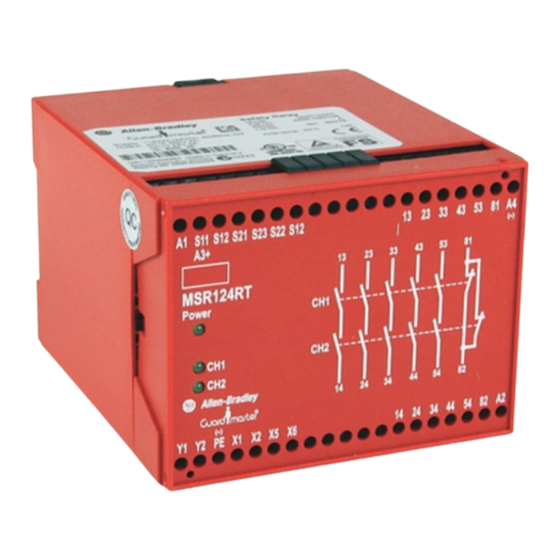
Minotaur MSR124RT Monitoring Safety Relay
Bulletin Number 440R
Summary of Changes
This publication contains the following new or updated information. This list
includes substantive updates only and is not intended to reflect all changes.
Topic
Updated Declaration of Conformity
Introduction
This device is intended to be part of the safety-related control system of a
machine.
Before installation, you must perform a risk assessment to determine whether the
specifications of this device are suitable for all foreseeable operational and
environmental characteristics of the machine to which it is fitted. At regular
intervals during the life of the machine, check whether the foreseen
characteristics remain valid.
WARNING: Danger of serious injury. Misuse can result in
malfunction.
• Only authorized and trained personnel can start, assemble, or
retrofit the device.
• Installation must be in accordance with the following steps.
WARNING: Danger of serious injuries. Incorrect installation or
manipulation can result in serious injuries.
• Do not defeat, tamper, remove, or bypass this unit.
Rockwell Automation does not accept responsibility for failure of this device if you
do not implement the procedures that are given in this publication, or if you use
the unit outside the recommended specifications that are listed in this publication.
IMPORTANT
The safety inputs of these products are described as
normally closed (N.C.), that is, with the guard closed, the
actuator in place (where relevant), and the machine able to
start. You must prevent exposure to shock and/or vibration
in excess of those specifications in IEC 60068 part: 2-6/7.
Adherence to the recommended inspection and
maintenance instructions forms part of the warranty.
IMPORTANT
All information complies with the state of this publication
and is subject to change without notice.
Repair
If any malfunction or damage is present, do not attempt to repair. Replaced the
unit before machine operation is allowed.
IMPORTANT
Do not dismantle the unit.
Functional Description
The safety-related function is the instant interruption of the safety-related contact
paths. MSR124 safety relay can be used as a safety guard monitor or as an
E-stop relay in single or dual-channel applications. The dual-channel operation
that is shown in
Page
E-stop circuits. Shorts between the two E-stop channels of MSR124 safety relay
3
de-energize the outputs. De-energization is achieved by an electronic protection
circuit in the safety relay. After elimination of the malfunction, the MSR124 safety
relay is ready for operation again. The application with monitored start checks the
start circuit (Y1-Y2) and only activates the MSR124 safety relays if there is a leading
edge in this circuit. The recovery time in this function must be at least 5 seconds.
If wired for the autostart function (X5 and X6 linked), the MSR124 safety relay
activates automatically once the E-stop circuits and the feedback loop (X1-X2)
closes. In autostart applications, where both E-stop circuits do not close
simultaneously (for example, safety gates), channel 2 must activate before channel
1. MSR124 safety relay can be supplied either with the rated AC voltage via terminals
A1-A2, or with 24V DC supply to be connected via terminals A3-A4.
Specifications
Table 1 - Technical Specifications
Attribute
Functional safety data
Power supply
Power consumption
Safety inputs
Input simultaneity
Allowable input resistance,
max
Outputs
Output rating
Fuses output (external)
Switched current/voltage, min 10 mA/10V
Thermic current/l
th
Contact material
Figure 4 on page 2
includes cross fault monitoring between both
Description
According to ISO 13849-1:
• PLe, Cat. 4
• MTTF
[a]: 416
d
• DC average: 99%
According to IEC 62061 and IEC 61508:
• SIL CL 3
• PFH [1/h]: 2.00E-09
• HFT: 1
• DC: 99%
• TM (PTI) [a]: 20
(1)
• dop [d]/hop [h]
: 365/24
(2)
• tcycle [h]/[s]
: 8/28,800
24V AC/DC, 115/230V AC, and 24V DC (A3-A4)
0.8...1.1 x rated voltage 50/60 Hz
(0.85...1.1 x 24V DC)
3 W
1 N.C. or 2 N.C., or light curtain
Infinite
50 Ω
5 N.O. safety, 1 N.C. auxiliary
• UL: B300
6 A/240V AC
• AC-15: 4 A/250V AC
• DC-13: 2 A/24V DC
6 A slow blow or 10 A quick blow
According to the derating diagram (maximum 10 A in one current path)
AgSnO
+ 0.5µAu
2
Advertisement

Related Manuals for Rockwell Automation Allen-Bradley Guardmaster MSR124RT


Summary of Contents for Rockwell Automation Allen-Bradley Guardmaster MSR124RT
- Page 1 Functional safety data • PFH [1/h]: 2.00E-09 • HFT: 1 Rockwell Automation does not accept responsibility for failure of this device if you • DC: 99% do not implement the procedures that are given in this publication, or if you use •...
- Page 2 Manual monitored reset Positive Edge: The unit is active once the safety input circuit closes and once the reset circuit closes after the waiting period has elapsed (see Declaration of Conformity on page Rockwell Automation Publication 440R-IN082B-EN-P - July 2022...
- Page 3 X5, X6 Automatic reset 13, 14, 23, 24, 33, 34, 43, Safety output N.O. Rockwell Automation declares that the products that are shown in this document 44, 53, 54 conform with the Essential Health and Safety Requirements (EHSRs) of the...
- Page 4 Rockwell Otomasyon Ticaret A.Ş. Kar Plaza İş Merkezi E Blok Kat:6 34752 İçerenköy, İstanbul, Tel: +90 (216) 5698400 EEE Yönetmeliğine Uygundur Allen-Bradley, expanding human possibility, Guardmaster, Minotaur, and Rockwell Automation are trademarks of Rockwell Automation, Inc. Trademarks not belonging to Rockwell Automation are property of their respective companies.
Need help?
Do you have a question about the Allen-Bradley Guardmaster MSR124RT and is the answer not in the manual?
Questions and answers