Table of Contents
Advertisement
Quick Links
User's and Programmer's Reference
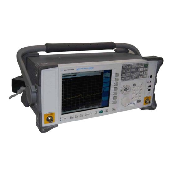
Agilent CSA Spectrum Analyzer
This manual provides documentation for the following instruments:
N1996A-503 (100 kHz to 3 GHz)
N1996A-506 (100 kHz to 6 GHz)
For firmware revision A.01.10 and above
Manufacturing Part Number: N1996-90002
Printed in USA
May 2006
© Copyright
2006 Agilent Technologies, Inc.
Advertisement
Chapters
Table of Contents

Related Manuals for Agilent Technologies N1996A-503


Summary of Contents for Agilent Technologies N1996A-503
- Page 1 User’s and Programmer’s Reference Agilent CSA Spectrum Analyzer This manual provides documentation for the following instruments: N1996A-503 (100 kHz to 3 GHz) N1996A-506 (100 kHz to 6 GHz) For firmware revision A.01.10 and above Manufacturing Part Number: N1996-90002 Printed in USA May 2006 ©...
- Page 2 The information contained in this document is subject to change without notice. Agilent Technologies makes no warranty of any kind with regard to this material, including but not limited to, the implied warranties of merchantability and fitness for a particular purpose. Agilent Technologies shall not be liable for errors contained herein or for incidental or consequential damages in connection with the furnishing, performance, or use of this material.
-
Page 3: Table Of Contents
Contents 1. Using This Document ..........19 About the User’s and Programmer’s Information . - Page 4 Contents Adjacent Channel Power—ACP (I&M) Measurement ......126 Adjacent Channel Power—ACP (I&M) Description ......126 AMPTD Y Scale .
- Page 5 Contents Meas Setup ............233 Trace/Detector .
- Page 6 Contents Generating a Service Request ..........330 Status Register System .
- Page 7 List of Commands *CLS ................344 *ESE .
- Page 8 List of Commands :CALCulate:LMASk[1]|2:SEGMent:CENTer:LEVel? ........63 :CALCulate:LMASk[1]|2:SEGMent:CENTer:SPAN <frequency>...
- Page 9 List of Commands :CALCulate:MASk[1]|2:FIRSt:SEGMent:RIGHt:LEVel? ....... . . 66 :CALCulate:OBWidth:LMASk[1]|2:FIRSt:SEGMent:LEFT:LEVel <ampl>....114 :CALCulate:OBWidth:LMASk[1]|2:FIRSt:SEGMent:LEFT:LEVel? .
- Page 10 List of Commands :CALCulate:OBWidth:MARKer[1]|2|3|4:TRACe? ........101 :CALCulate:OBWidth:MARKer[1]|2|3|4[:SET]:CENTer .
- Page 11 List of Commands :DISPlay:ANNotation:CLOCk:DATE:FORMat? ........276 :DISPlay:ANNotation:CLOCk[:STATe] OFF|ON|0|1.
- Page 12 List of Commands :INSTrument[:SELect] SA|SR|CHAN..........27 :INSTrument[:SELect]? .
- Page 13 List of Commands :STATus:QUEStionable:INTegrity:PTRansition? ........359 :STATus:QUEStionable:INTegrity[:EVENt]? .
- Page 14 List of Commands :TRACe[1]|2|3|4:UPDate[:STATe] ON|OFF|1|0 ........80 :TRACe[1]|2|3|4:UPDate[:STATe]?.
- Page 15 List of Commands [:SENSe]:BANDwidth|BWIDth[:RESolution]AUTO OFF|ON|0|1 ......38 [:SENSe]:BANDwidth|BWIDth[:RESolution]AUTO? ........38 [:SENSe]:CORRection:OFFSet[:MAGNitude] <rel_ampl>.
- Page 16 List of Commands [:SENSe]:OBWidth:AVERage:COUNt?..........108 [:SENSe]:OBWidth:AVERage:TCONtrol EXPonential|REPeat|RMAXhold.
- Page 17 List of Commands [:SENSe]:SWEep:TIME <time> ........... . . 252 [:SENSe]:SWEep:TIME? .
- Page 18 List of Commands...
-
Page 19: Using This Document
Using This Document The Agilent CSA is a portable radio frequency (RF) (3 or 6 GHz) spectrum analyzer. It has several different measurement Modes. Each mode offers a set of automatic measurements that pre-configure the analyzer settings for ease of use. The latest instrument software and documentation can be found at: http://www.agilent.com/find/csa... -
Page 20: About The User's And Programmer's Information
Using This Document About the User’s and Programmer’s Information About the User’s and Programmer’s Information This document provides user and programmer information for the spectrum analyzer functions. NOTE The front- and rear-panel features, along with the numeric keypad and alpha-numeric softkey fundamentals, are illustrated and described in the “Getting Started”... -
Page 21: Terms Used In This Book
Using This Document About the User’s and Programmer’s Information Terms Used in This Book There are many terms used throughout this book, for example “active function block,” that are explained in detail in the “Getting Started” chapter of the measurements guide. It is recommended that you read that section first. - Page 22 Using This Document About the User’s and Programmer’s Information Chapter 1...
-
Page 23: Meas
Meas This key displays a menu that lets you to make one-button measurements such as adjacent channel power and occupied bandwidth measurements. In the Spectrum Analysis mode (see the Mode key), the default status is measurement off. This default allows you to make your measurements specifying your unique setup requirements. -
Page 24: Current Measurement Data Query (Remote Command Only)
Meas Current Measurement Data Query (Remote Command Only) Current Measurement Data Query (Remote Command Only) This command returns data from the currently running measurement. A measurement Meas must be selected under the key. The response will be in a block format that consists of a block of data bytes. -
Page 25: Current Measurement Query (Remote Command Only)
Meas Current Measurement Query (Remote Command Only) Current Measurement Query (Remote Command Only) This command returns the name of the measurement that is currently running. Mode Remote Command :CONFigure? Example CONF? Remote Command Notes Returns current measurement name Chapter 2... - Page 26 Meas Current Measurement Query (Remote Command Only) Chapter 2...
-
Page 27: Mode
Mode Accesses menu keys enabling you to select the measurement mode of your analyzer. Spectrum Analysis mode is the default mode and is for general-purpose measurement use. Additional measurement modes can be added to your instrument. Example modes include the Stimulus / Response Measurement Suite (requires Option TG3 or TG6). Other modes, besides Spectrum Analysis and Stimulus / Response, must be Mode installed/licensed in your instrument before they will appear in the... -
Page 28: Spectrum Analyzer
Mode Spectrum Analyzer Spectrum Analyzer Selects the Spectrum Analysis measurement mode for your analyzer. This mode allows you to make all your measurements specifying your unique setup requirements. The Spectrum Meas Analysis mode defaults to measurement off status. In addition, you may use the to select one-button measurements such as, Occupied BW (Occupied Bandwidth). - Page 29 Mode Spectrum Analyzer Remote Command Notes This command stops the current measurement and sets up the instrument for the specified measurement using the factory default instrument settings. It does not initiate the taking of measurement data. This command will always set :INITiate:CONTinuous OFF (single sweep mode) and place the instrument in the idle state.
-
Page 30: Meas Off (Spectrum Analyzer) Measurement
Mode Meas Off (Spectrum Analyzer) Measurement Meas Off (Spectrum Analyzer) Measurement Meas Off Meas Setup To configure measurement settings, select and then press . Pressing Control/Sweep enables you to restart a measurement. Refer to the “Control/Sweep” on page Meas Off Measurement Description This key accesses the core spectrum analysis measurement functionality and turns off the current one-button measurement. - Page 31 Mode Meas Off (Spectrum Analyzer) Measurement AMPTD Y Scale, Autoscale Key Path Reference Level Sets the reference level value used for amplitude measurements. The reference level is the amplitude power or voltage represented by the top graticule line on the display. Changing the value of the reference level changes the absolute amplitude level of the top graticule line.
- Page 32 Mode Meas Off (Spectrum Analyzer) Measurement Dependencies / Couplings When the Auto Ranging is On, this value is automatically determined by the measurement. When the user sets a value manually, Auto Ranging automatically changes to Off. Preset 0 dB State Saved Saved in State Range 0 dB to 40 dB...
-
Page 33: Unit:power Dbm|Dbmv|Dbuv|V|W|A
Mode Meas Off (Spectrum Analyzer) Measurement Range Log | Lin AMPTD Y Scale, Scale Type Key Path Auto Range For the “Electronic Attenuation” parameter, when the “Auto Range” is ON the entire frequency range of the analyzer is scanned to determine the total power applied to the analyzer. - Page 34 Mode Meas Off (Spectrum Analyzer) Measurement AMPTD Y Scale, More (2 of 2), Y Axis Units Key Path dBm Sets the amplitude unit for the selected amplitude scale (log/lin) to dBm. Example UNIT:POW DBM AMPTD Y Scale, More (2 of 2), Y Axis Units, dBm Key Path dBmV Sets the amplitude unit for the selected amplitude scale (log/lin) to dBmV.
- Page 35 Mode Meas Off (Spectrum Analyzer) Measurement dBuV Sets the amplitude unit for the selected amplitude scale (log/lin) to dBµV. Example UNIT:POW DBUV AMPTD Y Scale, More (2 of 2), Y Axis Units, dBuV Key Path Watts Sets the amplitude unit for the selected amplitude scale (log/lin) to watts. Example UNIT:POW W AMPTD Y Scale, More (2 of 2), Y Axis Units, Watts...
-
Page 36: Auto Tune
Mode Meas Off (Spectrum Analyzer) Measurement Notes If the preamplifier option (Option P03 or P06) is not installed or is unlicensed, the key is grayed out and displays OFF as a state. Dependencies / Couplings When Auto Range is On, the state of this Preamp is automatically determined by the measurement. - Page 37 Mode Meas Off (Spectrum Analyzer) Measurement Auto Tune resolution at the new span. However, repeated use of the key will continue zooming in and centering the signal. Mode Key Path Front-panel key Undo Auto Tune Undo Auto Tune sets the center frequency back to the center frequency in effect prior to Auto Tune pressing the key.
-
Page 38: Demod
Mode Meas Off (Spectrum Analyzer) Measurement Remote Command [:SENSe]:BANDwidth|BWIDth[:RESolution] <freq> [:SENSe]:BANDwidth|BWIDth[:RESolution]? [:SENSe]:BANDwidth|BWIDth[:RESolution]AUTO OFF|ON|0|1 [:SENSe]:BANDwidth|BWIDth[:RESolution]AUTO? Example BAND:RES 3MHz BAND:RES:AUTO OFF Restrictions and Notes If an unavailable bandwidth is entered with the numeric keypad, the closest available bandwidth is selected. Dependencies / Sweep time in non-zero span is coupled to RBW. - Page 39 Mode Meas Off (Spectrum Analyzer) Measurement Center Frequency Sets the frequency that corresponds to the horizontal center of the graticule. The SCPI commands only change the Center Frequency for the current application. For example, in SA mode, the Center Frequency SCPI command only changes the Center Frequency for SA.
- Page 40 Mode Meas Off (Spectrum Analyzer) Measurement Units Freq Dependencies / Couplings Not displayed on front-panel when is set to The “Channel” parameter is coupled with the “Center Frequency” parameter and is dependent on the Channel Standard selected for the measurement. For instance, if the “Channel Standard”...
- Page 41 Mode Meas Off (Spectrum Analyzer) Measurement Default Unit Stop Freq Sets the frequency at the right side of the graticule. Stop Freq When reaches the lower frequency limit, the start frequency is set to the lowest available frequency and the stop frequency is changed to be more than the start frequency Center Freq by the minimum span (1 will be updated to the start frequency plus...
- Page 42 Mode Meas Off (Spectrum Analyzer) Measurement Dependencies / Couplings Span, RBW, Center Frequency When auto-coupled in a non-zero span, the center frequency step size is set to 10% of the span. When auto-coupled in zero span, the center frequency step size is set to the RBW value. Units Chan Not displayed on front-panel when...
- Page 43 Mode Meas Off (Spectrum Analyzer) Measurement Freq Channel, Units Key Path Chapter 3...
- Page 44 Mode Meas Off (Spectrum Analyzer) Measurement Chan STD “Chan STD” allows you to select a specific Radio Standard for the measurement. Depending on the Standard selected, the Channel parameters (Channel/Start Freq/Stop Freq) will be set to the appropriate values associated to the standard. Similarly, the Start Frequency, Center Frequency/Span, Stop Frequency values displayed on the X Axis of the graph will be updated accordingly.
-
Page 45: Marker
Mode Meas Off (Spectrum Analyzer) Measurement Notes This “Units” parameter is a Front Panel parameter only and is only visible/accessible if the “Units” parameter is set to “Chan”. Remote Command No SCPI command. Front Panel only. Notes Range None | North American Cellular CDMA | North American PCS CDMA | Japan CDMA | Korean PCS CDMA | Secondary 800 CDMA | IMT–2000 cdma2000 | GSM–850 | GSM–900 | EGSM–900 | GSM DCS–1800 | GSM PCS–1900 | North... - Page 46 Mode Meas Off (Spectrum Analyzer) Measurement Marker, Marker Key Path Normal Activates a single marker at the center of the display. Mode Example CALC:MARK2:POS POS selects marker 2 in the normal position type marker mode. Remote Command Notes See Marker Marker, Normal Key Path Delta...
-
Page 47: Calculate:marker[1]|2|3|4:Trace
Mode Meas Off (Spectrum Analyzer) Measurement Marker, Off Key Path Marker Trace Marker Trace Assigns a marker to a trace. If a marker is currently active, press until is highlighted. The active marker will be moved to the selected trace. Mode Remote Command :CALCulate:MARKer[1]|2|3|4:TRACe <integer>... - Page 48 Mode Meas Off (Spectrum Analyzer) Measurement Any trace have Use low est numbered both Update and trace w ith Update and Display on? Display on Any trace have Use low est numbered Display on? trace w ith Display on Any trace have Use low est numbered update on? trace w ith Update on...
-
Page 49: Calculate:marker[1]|2|3|4:X:readout Frequency|Time|Itime|Period
Mode Meas Off (Spectrum Analyzer) Measurement Remote Command :CALCulate:MARKer[1]|2|3|4:X:READout FREQuency|TIME|ITIMe|PERiod :CALCulate:MARKer[1]|2|3|4:X:READout? SCPI Example CALC:MARK3:X 1GHz activates the Marker3 and positions it on the trace at 1GHz. Remote Command Notes This feature is only available for the SA measurement in Spectrum Analyzer Mode. In Time Domain, only “Time”... - Page 50 Mode Meas Off (Spectrum Analyzer) Measurement Marker, Marker Readout, Period Key Path Dependencies / Couplings Only available when x axis scale is frequency. Mode Spectrum Analyzer with Meas OFF Remote Command See details in “Marker Readout (Marker X Axis Scale Type)” Table described above SCPI Example CALC:MARK2:X:READ FREQ sets marker 2 with a Marker...
-
Page 51: Calculate:marker:aoff
Mode Meas Off (Spectrum Analyzer) Measurement Inverse Time Sets the Marker Readout (Marker X Axis scale) to Inverse Time, displaying the reciprocal of the marker delta time. It is useful in a delta mode to show the reciprocal of (sweep) time between two markers. This function is only meaningful when on a time domain trace and in the Delta control mode. -
Page 52: Calculate:marker[1]|2|3|4:X
Mode Meas Off (Spectrum Analyzer) Measurement mode is Normal or Delta. Parameter Name Marker X Axis Value Parameter Type Float64 Mode Spectrum Analyzer SCPI Name Marker X Axis Value Remote Command :CALCulate:MARKer[1]|2|3|4:X <real> :CALCulate:MARKer[1]|2|3|4:X? SCPI Example CALC:MARK3:X 1GHz activates the Marker3 and positions it on the trace at 1 GHz. - Page 53 Mode Meas Off (Spectrum Analyzer) Measurement Determined by the min value used by the X Axis Scale. In Frequency Domain, per default, Start Frequency (starting point of the Frequency X axis scale) is 100 kHz, so the Marker X Axis Min value that can be entered is 100 kHz. The Marker X Axis Min Value that can be used is -35 MHz (it's the minimum value that the Start Freq can accept) In Time Domain, per default, the Marker X Axis Min value is 0...
-
Page 54: Calculate:marker[1]|2|3|4:X:position
Mode Meas Off (Spectrum Analyzer) Measurement SCPI Resolution Determined by the number of sweep points and type/start/stop of the X Axis scale. - With a Frequency X Axis scale, Resolution = (Stop Freq - Start Freq) / (Sweep points - 1) Example - With default settings after a preset (6 GHz Instrument): Resolution = (6 GHz - 100 kHz) / (401 -1) = 14999.75 kHz... -
Page 55: Calculate:marker[1]|2|3|4:Y
Mode Meas Off (Spectrum Analyzer) Measurement Preset/Default Center of screen - Number of sweep points per default is 401(X position scale goes from 0 to 400), so the default center position is 200 State Saved This Max value will clip to the value set for the number of sweep points. - Page 56 Mode Meas Off (Spectrum Analyzer) Measurement Remote Command Notes You must be in the SA mode to use this command. Use INSTrument:SELect to set the mode. The query returns the marker Y-axis result. If the marker is Off the response is not a number. Preset/Default Current Marker Y Axis value in the marker Y Axis unit State Saved...
-
Page 57: Marker
Mode Meas Off (Spectrum Analyzer) Measurement Marker -> Accesses the marker function menu keys that change value of center frequency or reference level to the current value of the selected marker. Mode Spectrum Analyzer Marker -> Key Path Mkr -> CF Sets the center frequency equal to the specified marker frequency, which moves the marker to the center of the screen. -
Page 58: [:Sense]:Average:tcontrol Exponential|Repeat|Rmaxhold
Mode Meas Off (Spectrum Analyzer) Measurement Mode: Key Path Front-panel key Avg Mode Sets the type of termination control used for the averaging function. This determines the Avg Number averaging action after the specified number of measurements (see ) has been reached. -
Page 59: [:Sense]:Average:count
Mode Meas Off (Spectrum Analyzer) Measurement running – the trace is not updated until the last average count has been reached. Example AVER:TCON REP Meas Setup, Avg Mode, Repeat Key Path Repeat Max Hold Sets Avg Mode to repeat with max hold function. Repeat with max hold captures and holds the highest magnitude data at the end of each sweep count. -
Page 60: [:Sense]:Average:type Rms|Log
Mode Meas Off (Spectrum Analyzer) Measurement the measurement to logarithmic (video) averaging, or power (RMS) averaging. Trace Trace/Detector Average averaging is turned on by pressing Mode Remote Command [:SENSe]:AVERage:TYPE RMS|LOG [:SENSe]:AVERage:TYPE? Example AVERage:TYPE RMS|LOG AVERage:TYPE? Preset Log-Pwr Avg (Video) State Saved Saved in instrument state. -
Page 61: Calculate:lmask[1]|2:Trace 1|2|3|4
Mode Meas Off (Spectrum Analyzer) Measurement Mode Spectrum Analyzer Dependencies / The Limit Mask 1 (Upper) menu link key accesses the keys to Couplings configure the upper limit mask for the Center, 1 , or 2 segments (dependent on selected segment). The Limit Mask 2 (Lower) menu link key accesses the keys to configure the lower limit mask for the Center, 1 , or 2... -
Page 62: Calculate:lmask[1]|2:Segment:center[:State] On|Off|1|0
Mode Meas Off (Spectrum Analyzer) Measurement Range 1 | 2 | 3 | 4 Meas Setup, Limit Masks, Limit Mask 1, Limit Trace Key Path Segment (Center, 1st or 2nd) Center Selects the segment for limit mask 1 or 2. With each segment setting, the Limits menu is updated to show the span and level settings available for the currently selected segment Mode Dependencies /... -
Page 63: Calculate:lmask[1]|2:Segment:center:level
Mode Meas Off (Spectrum Analyzer) Measurement Dependencies / If Off no limit mask will be displayed even if the 1 or 2 Couplings segments are turned On. If On the center segment is drawn on the display centered around the current center frequency. Preset State Saved Saved in instrument state. -
Page 64: Calculate:lmask[1]|2:Segment:first On|Off|1|0
Mode Meas Off (Spectrum Analyzer) Measurement Example :CALC:LMAS1:SEGM:CENT:SPAN 1.75 MHz Notes Key is only displayed when the selected segment is Center. Preset Not affected by a preset but set per default to 2 MHz after a power cycling. State Saved Saved in instrument state. -
Page 65: Calculate:lmask[1]|2:First:segment:left:level
Mode Meas Off (Spectrum Analyzer) Measurement Meas Setup, Limit Masks, Limit Mask 1, 1st Segment Key Path 1st Segment (Left or Right Limits) 1st Segment Sets to allow definition of the limits Left or Right of the center segment. The Left or Level Right amplitude limits can be changed with the key. -
Page 66: Calculate:lmask[1]|2:Segment:first:left:span
Mode Meas Off (Spectrum Analyzer) Measurement Preset Not affected by a preset but set per default to –30 dBm after a power cycling State Saved Saved in instrument state. Meas Setup, Limit Masks, Limit Mask 1, 1st Segment: Left, Level Key Path Default Unit Level: 1st Segment Right... -
Page 67: Calculate:lmask[1]|2:Segment:first:right:span
Mode Meas Off (Spectrum Analyzer) Measurement Notes Key is only displayed when the selected segment is 1 , and the selected segment side is Left. Dependencies / If the Center, 1 , and 2 segments are On, the left 2 segment Couplings span adjusts on a change in the left 1... -
Page 68: Calculate:lmask[1]|2:Segment:second On|Off|1|0
Mode Meas Off (Spectrum Analyzer) Measurement 2nd Segment Sets the state of the first segment to On or Off. This key is available only when 2 has been selected with the Segments key. Mode Remote Command :CALCulate:LMASk[1]|2:SEGMent:SECond ON|OFF|1|0 :CALCulate:LMASk[1]|2:SEGMent:SECond? Example :CALC:LMAS1:SEGM:SEC ON Notes Key is only displayed when the selected segment is 2... -
Page 69: Calculate:lmask[1]|2:Second:segment:left:level
Mode Meas Off (Spectrum Analyzer) Measurement Dependencies / The Left span is calculated as follows: Couplings (<maximum span>/2) – (<center segment span>/2) - <first segment left span> The Right span is calculated as follows: (<maximum span>/2) – (<center segment span>/2) - <first segment right span>... -
Page 70: Calculate:lmask[1]|2:Second:segment:right:level
Mode Meas Off (Spectrum Analyzer) Measurement Default Unit Level: 2nd Segment Right Sets the power level, for the 2 segment to the Right of the Center segment. This key is only Segments available when has been selected with the key. Mode Remote Command :CALCulate:LMASk[1]|2:SECond:SEGMent:RIGHt:LEVel... -
Page 71: Trigger[:Sequence]:Source Immediate|External|Rfburst|Video
Mode Meas Off (Spectrum Analyzer) Measurement Trigger Displays the trigger settings menu. The Trigger menu is only available in zero span. In non-zero span, the trigger type is always free run. When using a trigger source other than Free Run, the analyzer will begin a sweep only with the trigger conditions are met. -
Page 72: Trg
Mode Meas Off (Spectrum Analyzer) Measurement Remote Command Notes IMMediate – free run triggering EXTernal – triggers on an externally connected trigger source on the rear panel RFBurst – triggers on the bursted frame VIDeo – triggers on the video signal level Other trigger-related commands are found in the INITiate and ABORt subsystems. -
Page 73: Trigger[:Sequence]:Level:absolute
Mode Meas Off (Spectrum Analyzer) Measurement External Sets an external input signal as the trigger source. A new sweep/measurement will start when the external trigger condition is met by the signal applied at the External Trigger Input. Example TRIG:SOUR EXT This selects the external trigger input. Remote Command Notes See Trigger Dependencies / Couplings... -
Page 74: Trigger[:Sequence]:Delay
Mode Meas Off (Spectrum Analyzer) Measurement Dependencies / Couplings The range of the Video Trigger Level is dependent on the Reference Level. Trigger level selection is not available with free run or external triggering. Meas Setup, Trigger, Trigger Level Key Path Trig Slope Controls the trigger polarity. -
Page 75: Peak Search
Mode Meas Off (Spectrum Analyzer) Measurement Meas Setup, Trigger, Trig Delay Key Path Auto Trig Sets the time that the analyzer will wait for the trigger conditions to be met. If they are not met after that much time, then the analyzer is triggered anyway. Auto Trig defaults to off and is not accessible remotely. -
Page 76: Span/X Scale (Spectrum Analyzer Measurement)
Mode Meas Off (Spectrum Analyzer) Measurement Span/X Scale (Spectrum Analyzer Measurement) Activates the span functions menu. The menu selections are determined by the current measurement mode. Mode Preset Full span (depends on hardware present – options) State Saved Saved in State Key Path Front-panel key Span... - Page 77 Mode Meas Off (Spectrum Analyzer) Measurement Range 0 Hz, 1 kHz to 3.00 GHz (Option 503) 0 Hz, 1 kHz to 6.00 GHz (Option 506) Span/X Scale, Span Key Path Full Span Changes the displayed frequency span to show the full frequency range of the analyzer. Mode Remote Command [:SENSe]:FREQuency:SPAN:FULL...
-
Page 78: Trace/Detector
Mode Meas Off (Spectrum Analyzer) Measurement Trace/Detector Trace/Detector Accesses the menu keys that control the acquisition, display, storage, detection and manipulation of trace data. Mode Remote Command :TRACe[1]|2|3|4:TYPE WRITe|AVERage|MAXHold|MINHold :TRACe[1]|2|3|4:TYPE? Example TRAC:TYPE AVER Remote Command Notes 1|2|3|4 selects the trace. Preset Write. - Page 79 Mode Meas Off (Spectrum Analyzer) Measurement instrument begins a new sweep and the trace is updated. Example TRAC:TYPE WRIT Clear Write Dependencies / Couplings Whenever the user presses or sends the equivalent SCPI , Update Display Show command is set to is set to State Saved The type information for each trace is saved in Instrument State...
-
Page 80: Trace[1]|2|3|4:Update[:State] On|Off|1|0
Mode Meas Off (Spectrum Analyzer) Measurement State Saved The type information for each trace is saved in Instrument State Trace/Detector, Max Hold Key Path Min Hold Min Hold Pressing causes the trace to be cleared and a new minimum-hold measurement sequence to be started. - Page 81 Mode Meas Off (Spectrum Analyzer) Measurement Dependencies / Couplings Setting the trace type (even to the type it was already in) puts the Update = On trace in Loading a trace from a file makes that trace inactive regardless of the state it was in when it was saved.
- Page 82 Mode Meas Off (Spectrum Analyzer) Measurement Detector Accesses the detector selection menu. Manually selecting a detector turns off the automatic detector selection functionality. Mode Remote Command [:SENSe]:DETector:TRACe[1]|2|3|4[:FUNCtion] AVERage|POSitive|SAMPle|NEGative [:SENSe]:DETector:TRACe[1]|2|3|4[:FUNCtion]? [:SENSe]:DETector:TRACe[1]|2|3|4:AUTO OFF|ON|0|1 [:SENSe]:DETector:TRACe[1]|2|3|4:AUTO? Example TRAC2:TYPE WRIT DET:TRAC2 AVER This sets the selected trace to trace 2, sets its write mode and then sets the detector to average.
- Page 83 Mode Meas Off (Spectrum Analyzer) Measurement History The following Legacy Auto State command: [:SENSe]:DETector:AUTO ON | OFF | 1 | 0 [:SENSe]:DETector:AUTO? will be supported for Backwards Compatibility. The command [:SENSe]:DETector:AUTO will turn the AUTO state ON or OFF for ALL detectors. This implementation is required to preserve the classic functionality wherein all traces are affected when a detector is addressed Peak For each display point (interval) on the trace, Peak detection displays the highest...
- Page 84 Mode Meas Off (Spectrum Analyzer) Measurement Example DET:TRAC2 NEG sets trace 2 to negative peak detection. Trace/Detector, Detector, Negative Peak Key Path Average For each display point (interval) on the trace, Average detection displays the power average (RMS) of the amplitude within the frequency interval represented by that display point.
- Page 85 Mode Meas Off (Spectrum Analyzer) Measurement Clear All Traces Clears all traces. Does not affect the state of any function or variable in the box. Loads minimum trace value into all of the points all traces, except traces in Min Hold in which case it loads maximum trace value.
- Page 86 Mode Meas Off (Spectrum Analyzer) Measurement Remote Command :TRACe[:DATA] <trace_name>, <definite_length_block>| <comma_separated_ASCII_data> :TRACe[:DATA]? <trace_name> where <trace_name> = TRACE1|TRACE2|TRACE3|TRACE4 Dependencies / Couplings the FORMat:DATA command describes the different types of data formats that can be used with trace data. use the FORMat:BORDer command to set the byte order. Remote Command :TRACe[:DATA]? TRACE1 | TRACE2 | TRACE3 | TRACE4 Example...
-
Page 87: View/Display (Spectrum Analyzer Mode)
Mode Meas Off (Spectrum Analyzer) Measurement Example FORM:DATA ASCii With 4 points looks like: –5.87350E+01, –5.89110E+01, –5.87205E+01, –5.12345E+01<NL><END> FORM:DATA INT,32 With 4 bytes per point looks like: #216<16 bytes of data><NL><END> Where the 2 in the #216 means “2 digits of numeric data to follow”, and the 16 is the 2 digits and means “16 binary bytes to follow”... - Page 88 Mode Meas Off (Spectrum Analyzer) Measurement Key Path Front-panel key Spectrogram Accesses the spectrogram display menu. The spectrogram function is only available when Option 271 has been installed. View/Display, Spectrogram Key Path: Spectrogram On/Off Turns the spectrogram display mode on/off. Mode Preset State Saved...
- Page 89 Mode Meas Off (Spectrum Analyzer) Measurement Preset Max Speed (0 s.) State Saved Saved in State 400 nS (200*1024)/(2*RBW) View/Display, Spectrogram, Update Interval Key Path Frame Skip Enables you to set the number of frames you would like to skip when capturing data.
- Page 90 Mode Meas Off (Spectrum Analyzer) Measurement • For security purposes If you have turned off the display and you are in local operation, the display can be turned back on by sending the DISPlay:ENABle ON command (neither *RST nor SYSTem:PRESet enable the display.) Mode Remote Command :DISPlay:ENABle OFF|ON|0|1...
-
Page 91: Occupied Bandwidth Measurement
Mode Occupied Bandwidth Measurement Occupied Bandwidth Measurement Occupied BW Meas Setup To configure measurement settings, select and then press Control/Sweep Pressing enables you to pause or restart a measurement, or toggle between continuous and single measurement, refer to “Control/Sweep” on page Occupied BW—OBW Measurement Description Occupied Bandwidth integrates the power of the displayed spectrum and puts markers at the frequencies between which a selected percentage of the power is contained. -
Page 92: Calculate:data
Mode Occupied Bandwidth Measurement Time Stamp Time of measurement, instrument clock Nanoseconds in nanoseconds Occupied BW Start Index Zero-based index into the Trace field that is the beginning of the Occupied Bandwidth. If the measurement was not made it will contain the value 9.91E37 Occupied BW Stop Index Zero-based index into the Trace field that is the end of the Occupied Bandwidth. -
Page 93: Amptd Y Scale
Mode Occupied Bandwidth Measurement Example CONF:OBW selects the OBW measurement. INIT:IMM starts a measurement cycle. *OPC? holds off the return of data until the above commands have completed. CALCulate:DATA? returns the measurement data. Notes You must be in the Spectrum Analyzer mode and in the OBW measurement in order to get the OBW results using this CALCulate:DATA?query. - Page 94 Mode Occupied Bandwidth Measurement Remote Command :DISPlay:OBWidth:WINDow:TRACe:Y[:SCALe]:RLEVel <ampl> :DISPlay:OBWidth:WINDow:TRACe:Y[:SCALe]:RLEVel? Example :DISP:OBW:WIND:TRAC:Y:RLEV 10dBm Preset 0 dBm State Saved Saved in State –150 dBm 100 dBm AMPTD Y Scale, Reference Level Key Path Auto Range / Elec Atten / Internal preamp Auto Range, the electronic attenuator and the internal preamp functionality is shared across all the Modes.
-
Page 95: Unit:obwidth:power Dbm|Dbmv|Dbuv|V|W|A
Mode Occupied Bandwidth Measurement Scale Type (Lin) selected, the vertical divisions are scaled in logarithmic units. scales the vertical divisions linearly, and sets the default amplitude units to volts. Mode Remote Command :DISPlay:OBWidth:WINDow:TRACe:Y[:SCALe]:SPACing LINear|LOGarithmic :DISPlay:OBWidth:WINDow:TRACe:Y[:SCALe]:SPACing? Example DISP:OBW:WIND:TRAC:Y:PDIV LIN Preset State Saved Saved in State Range Log | Lin... -
Page 96: Auto Tune
Mode Occupied Bandwidth Measurement dBmV Sets the amplitude unit for the selected amplitude scale (log/lin) to dBmV. Example UNIT:OBW:POW DBMV AMPTD Y Scale, Y Axis Units, dBmV Key Path dBµV Sets the amplitude unit for the selected amplitude scale (log/lin) to dB µV. Example UNIT:OBW:POW DB micro V AMPTD Y Scale, Y Axis Units, dBµV... - Page 97 Mode Occupied Bandwidth Measurement about how Auto Tune operates, see “Auto Tune” on page Res BW Activates the resolution bandwidth function and displays the key. Key Path Front-panel key Res BW Selects the 3.01 dB resolution bandwidth (RBW) of the analyzer in 10% steps from 10 Hz to , plus bandwidths of 250 , 300 , and 1, 3, or 5...
-
Page 98: Control/Sweep
Mode Occupied Bandwidth Measurement Dependencies / Sweep time in non-zero span is coupled to RBW. As the RBW Couplings changes, the sweep time is changed to maintain amplitude calibration. When Res BW is set to Auto, resolution bandwidth is autocoupled to span. The factory default for the Span to RBW ratio is approximately 106:1 when auto coupled. -
Page 99: Freq Channel
Mode Occupied Bandwidth Measurement Preset The default value is auto-calculated. This default value will depend upon the span of the analyzer, which could be either 2.9999 GHz or 5.9999 GHz Key Path N/A - Remote Feature Only Restart, Single, Cont The sweep control functionality is shared across all the Modes. - Page 100 Mode Occupied Bandwidth Measurement Preset NORMal Marker, Marker Type Key Path Normal Activates a single marker at the center of the display. Mode Example CALC:OBW:MARK2:MODE NORM selects marker 2 in NORM mode Marker, Normal Key Path Delta Activates a pair of markers, one of which is fixed at the current marker location. The other marker can then be moved around on the trace.
-
Page 101: Calculate:obwidth:marker[1]|2|3|4:Trace
Mode Occupied Bandwidth Measurement Marker Trace are no markers turned on. If a marker is currently active, press until , or is underlined. The active marker will be moved to the selected trace. Mode Remote Command :CALCulate:OBWidth:MARKer[1]|2|3|4:TRACe <integer> :CALCulate:OBWidth:MARKer[1]|2|3|4:TRACe? :CALCulate:OBWidth:MARKer[1]|2|3|4:TRACe:AUTO OFF|ON|0|1 :CALCulate:OBWidth:MARKer[1]|2|3|4:TRACe:AUTO? Example CALC:OBW:MARK2:TRAC 4... - Page 102 Mode Occupied Bandwidth Measurement Any trace have Use low est numbered both Update and trace w ith Update and Display on? Display on Any trace have Use low est numbered Display on? trace w ith Display on Any trace have Use low est numbered update on? trace w ith Update on...
-
Page 103: Calculate:obwidth:marker:aoff
Mode Occupied Bandwidth Measurement Frequency Sets the marker readout to frequency. Mode Remote Command Notes Front panel capability only Marker, Marker Readout, Frequency Key Path Period Sets the marker readout to period. In non-zero span this is 1/frequency. Mode Remote Command Notes Front panel capability only Marker, Marker Readout, Period Key Path... -
Page 104: Marker
Mode Occupied Bandwidth Measurement Remote Command Notes CALC:OBW:MARK:AOFF Marker, Marker All Off Key Path Marker -> Accesses the marker function menu keys that change value of center frequency or reference level to the current value of the selected marker. Mode Key Path Front-panel key Mkr ->... -
Page 105: Meas
Mode Occupied Bandwidth Measurement Meas Meas key displays a menu that lets you make one-button measurements such as the occupied bandwidth measurement. In the Spectrum Analyzer mode (see “Spectrum Analyzer” on page 28), Measurements Off is the default measurement. You must select Occupied BW. - Page 106 Mode Occupied Bandwidth Measurement Preset EXPonential State Saved Saved in instrument state. Range Exponential | Repeat | Repeat Max Hold Meas Setup, Avg Mode Key Path Exponential Sets the Avg Mode function to exponential. With exponential averaging mode, each successive data acquisition is exponentially weighted and combined with the existing average.
- Page 107 Mode Occupied Bandwidth Measurement Example AVER:OBW:TCON RMAX Meas Setup, Avg Mode, Repeat Max Hold Key Path Chapter 3...
- Page 108 Mode Occupied Bandwidth Measurement Avg Number Sets the average count number (the number of sweeps) used with measurement averaging. Mode Remote Command [:SENSe]:OBWidth:AVERage:COUNt <integer> [:SENSe]:OBWidth:AVERage:COUNt? Example AVER:OBW:COUN 50 Preset 4096 Meas Setup, Avg Number Key Path Avg Type Accesses averaging settings that determine how the signal will be measured. You can set the measurement to logarithmic (video) scaling, or power (RMS) scaling.
- Page 109 Mode Occupied Bandwidth Measurement Meas Setup, Avg Type, Log-Pwr Avg (Video) Key Path Pwr Avg (RMS) Sets the signal power level (the square of the magnitude) as the scale for the filtering and averaging processes. This scale is sometimes called RMS because the resulting voltage is proportional to the square root of the mean of the square of the voltage.
-
Page 110: Calculate:obwidth:lmask[1]|2:Trace 1|2|3|4
Mode Occupied Bandwidth Measurement Mode Remote Command :CALCulate:OBWidth:LMASk[1]|2:TRACe 1|2|3|4 :CALCulate:OBWidth:LMASk[1]|2:TRACe? Example :CALC:OBW:LMAS1:TRAC 2 Dependencies / The limit mask is always displayed when the center segment is Couplings turned on; even if the trace to which it is being applied is blanked (‘Show’... -
Page 111: Calculate:obwidth:lmask[1]|2:Segment:center:level
Mode Occupied Bandwidth Measurement Center has been selected with the Segments key. Mode Remote Command :CALCulate:OBWidth:LMASk[1]|2:SEGMent:CENTer[:STATe] ON|OFF|1|0 :CALCulate:OBWidth:LMASk[1]|2:SEGMent:CENTer[:STATe] Example :CALC:OBW:LMAS1:SEGM:CENT ON Restrictions and Notes Key is only displayed when the selected segment is Center. Dependencies / If Off no limit mask will be displayed even if the 1 or 2 Couplings segments are turned On. -
Page 112: Calculate:obwidth:lmask[1]|2:Segment:center:span
Mode Occupied Bandwidth Measurement Span: Center Sets the frequency span for the center segment of the currently selected limit mask. This key is only available when Center has been selected with the Segment key. Mode Remote Command :CALCulate:OBWidth:LMASk[1]|2:SEGMent:CENTer:SPAN <frequency> :CALCulate:OBWidth:LMASk[1]|2:SEGMent:CENTer:SPAN? Example :CALC:OBW:LMAS1:SEGM:CENT:SPAN 1.75 MHz Notes... - Page 113 Mode Occupied Bandwidth Measurement Dependencies / If Off the 2 limit mask segment will not be displayed even if Couplings turned On. If On and the Center segment is On: The left hand side 1 segment is drawn to the left hand side of the center segment at the specified power level.
-
Page 114: Calculate:obwidth:lmask[1]|2:First:segment:left:level
Mode Occupied Bandwidth Measurement Level: 1st Segment Left Sets the power level, for the 1 segment to the Left of the Center segment. This key is only Segments available when has been selected with the key. Mode Remote Command :CALCulate:OBWidth:LMASk[1]|2:FIRSt:SEGMent:LEFT:LEV el <ampl>... -
Page 115: Calculate:obwidth:lmask[1]|2:Segment:first:left:span
Mode Occupied Bandwidth Measurement Preset Not affected by a preset but set per default to –10 dBm after a power cycling State Saved Saved in instrument state. Meas Setup, Limit Masks, Limit Mask 1, 1st Segment: Right Level Key Path Default Unit Span: 1st Segment Left Sets the frequency span for the 1... -
Page 116: Calculate:obwidth:lmask[1]|2:Segment:first:right:span
Mode Occupied Bandwidth Measurement Remote Command :CALCulate:OBWidth:LMASk[1]|2:SEGMent:FIRSt:RIGHt:SP AN <frequency> :CALCulate:OBWidth:LMASk[1]|2:SEGMent:FIRSt:RIGHt:SP Example :CALC:OBW:LMAS1:SEGM:FIRS:RIGH:SPAN 1.75 MHz Notes Key is only displayed when the selected segment is 2 , and the selected segment side is Right. Dependencies / If the Center, 1 , and 2 segments On, the right 2 segment Couplings... - Page 117 Mode Occupied Bandwidth Measurement Preset State Saved Saved in instrument state. Range On | Off Meas Setup, Limit Masks, Limit Mask 1, 2nd Segment Key Path 2nd Segment (Left or Right Limits) Sets the 2nd segment to allow definition of the limits Left or Right of the center segment for the 2 Level Segment.
-
Page 118: Calculate:obwidth:lmask[1]|2:Second:segment:right:level
Mode Occupied Bandwidth Measurement Sets the power level, for the 2 segment to the Left of the Center segment. This key is only Segments available when has been selected with the key. Mode Spectrum Analyzer Notes Key is only displayed when the selected segment is 2 , and the selected segment side is Left. -
Page 119: Peak Search
Mode Occupied Bandwidth Measurement The default setting is High, which optimizes dynamic range but may introduce distortion with large signal levels. Setting sensitivity to Low removes signal distortion, but may decrease dynamic range. Mode Remote Command [:SENSe]:OBWidth:POWer:SENSitivity LOW|HIGH [:SENSe]:OBWidth:POWer:SENSitivity? Preset High Range Low | High... -
Page 120: Span/X Scale
Mode Occupied Bandwidth Measurement Mode Remote Command :CALCulate:OBWidth:MARKer[1]|2|3|4:MAXimum Example :CALC:OBW:MARK2:MAX Key Path Front-panel key Next Peak Places the selected marker on the next highest signal peak from the current marked peak. Mode Remote Command :CALCulate:OBWidth:MARKer[1]|2|3|4:MAXimum:NEXT Example CALC:OBW:MARK2:MAX:NEXT Peak Search, Next Peak, Key Path Span/X Scale Activates the span functions menu. - Page 121 Mode Occupied Bandwidth Measurement Remote Command [:SENSe]:OBWidth:FREQuency:SPAN <frequency> [:SENSe]:OBWidth:FREQuency:SPAN? Example OBW:FREQ:SPAN 2MHz Remote Command Preset and Max values are dependent on Hardware (Options Notes 503 & 506) Preset 2.9999 GHz (Option 503) 5.9999 GHz (Option 506) State Saved Saved in State Range 1 kHz to 3.00 GHz (Option 503) 1 kHz to 6.00 GHz (Option 506)
-
Page 122: Trace/Detector
Mode Occupied Bandwidth Measurement Full Span Changes the displayed frequency span to show the full frequency range of the analyzer. Mode Remote Command [:SENSe]:OBWidth:FREQuency:SPAN:FULL Example OBW:FREQ:SPAN:FULL Preset Full Span Span/X Scale, Full Span Key Path Zero Span In the OBW measurement, this function is not available and the key is grayed out. The OBW measurement is a Frequency Domain measurement. - Page 123 Mode Occupied Bandwidth Measurement Mode Key Path Front-panel key Select Trace, Clear Write, Average, Max Hold, Min Hold, Update On/Off, Display Show/Blank, Clear Trace, Clear All Traces The trace features are shared across all the measurements in the Spectrum Analyzer Mode.
-
Page 124: View/Display
Mode Occupied Bandwidth Measurement Remote Command Notes The query returns a name that corresponds to the detector type as shown below, and indicates the setting for the specified trace. The RMS selection is identical to AVERage. If RMS has been selected, the query will return the “AVER”... -
Page 125: Channel Analyzer
Mode Channel Analyzer Channel Analyzer Selects the Channel Analyzer measurement mode for your analyzer. This mode enables Meas you to use the key to select one-button measurements such as, Adjacent Channel Power. The Channel Analyzer mode defaults to the Adjacent Channel Power measurement. - Page 126 Mode Adjacent Channel Power—ACP (I&M) Measurement Adjacent Channel Power ACP (I&M) Measurement — Adjacent Channel Power—ACP (I&M) Description Adjacent Channel Power (ACP (I&M)) is a measure of the power that leaks into adjacent transmit channels. The ACP measurements, as currently implemented, are suitable for quick checks in installation and maintenance (I&M) applications.
- Page 127 Mode Adjacent Channel Power—ACP (I&M) Measurement Primary Channel Frequency error (in Hz) for the Frequency Error requested primary channel. 3–7 Low Adjacent The powers (in dBc) for the “low” side Channel Powers adjacent channels. The first Adjacent Channel Count entries are used. Unused channels will contain the value 9.91E37.
- Page 128 Mode Adjacent Channel Power—ACP (I&M) Measurement Sensitivity Sensitivity of measurement. High sensitivity gives better dynamic range but may introduce some non-linear effects. 0 = Low 1 = High (Default) Note: You can not change these settings. Peak Power Mode Measure peak or average power. 0 = average, 1 = peak Note: You can not change these settings.
-
Page 129: Calculate:data
Mode Adjacent Channel Power—ACP (I&M) Measurement the size, i.e. 314. After this is the data in a comma separated list: –6.4232e+01: Primary Channel Power (in dBm) 7.130e+03: Primary Channel Frequency Error (in Hz) –1.5241e+01: Low Adjacent Channel Power (in dBc) . - Page 130 Mode Adjacent Channel Power—ACP (I&M) Measurement Reference Level Sets the reference level value used for amplitude measurements. The reference level is the amplitude power (expressed in current Y-axis units) represented by the top graticule line on the display. Changing the value of the reference level changes the absolute amplitude level of the top graticule line.
-
Page 131: [:Sense]:Acpower:sweep:time
Mode Adjacent Channel Power—ACP (I&M) Measurement Example :DISP:ACP:WIND:TRACe:Y:PDIV 10dB Preset 10.00 dB / Div State Saved Saved in State Range 1.0 to 20 AMPTD Y Scale, Scale/Div Key Path Control/Sweep Accesses the sweep and measurement control settings that can be changed when using the ACP measurement. - Page 132 Mode Adjacent Channel Power—ACP (I&M) Measurement FREQ Channel Accesses the frequency/channel settings that can be changed when using the ACP measurement. Mode: Key Path Front-panel key FREQ / Channel FREQ / Channel front-panel key displays the frequency or channel menu functions available with the adjacent channel power measurement.
- Page 133 Mode Adjacent Channel Power—ACP (I&M) Measurement Channel Step Sets the channel step size. Mode Channel Analyzer Preset State Saved Saved in instrument state. Range 1 to 100 FREQ/Channel, Channel Step Key Path Chan STD (Radio Std) Opens a table with a list of available channel standards such as North American Cellular CDMA, North American PCS CDMA, and Japan CDMA.
- Page 134 Mode Adjacent Channel Power—ACP (I&M) Measurement FREQ/Channel, Units Freq/Chan Key Path Center Frequency Sets the channel center frequency. Mode Channel Analyzer Remote Command [:SENSe]:FREQuency:CENTer <freq> [:SENSe]:FREQuency:CENTer? Example FREQ:CENT 1GHz FREQ:CENT? Preset 1.955 GHz The minimum value that can be set for this Center Frequency has to take into account the bandwidth of the Lower Adjacent Channels.
-
Page 135: [:Sense]:Acpower:average:tcontrol Exponential|Maxhold|Repeat|Rmaxhold
Mode Adjacent Channel Power—ACP (I&M) Measurement Default Unit Meas Meas This key displays a menu that lets you to make one-button measurements such as the adjacent channel power measurement. In the Channel Analyzer mode, Adjacent Channel Power is the default measurement. This default allows you to make immediate measurements using the current default setup. -
Page 136: [:Sense]:Acpower:average[:State] Off|On|0|1
Mode Adjacent Channel Power—ACP (I&M) Measurement Preset The averaging state default is OFF. If averaging was turned ON, the default averaging mode for the measurement would be EXPonential. State Saved Saved in State Range Exponential | Max Hold | Repeat | RMaxHold Meas Setup, Avg Mode Key Path Off Turns averaging functions off. -
Page 137: [:Sense]:Acpower:average:count
Mode Adjacent Channel Power—ACP (I&M) Measurement Meas setup, Avg Mode, Max Hold Key Path Repeat Sets the averaging function to the repeat function. Repeat averaging shows resulting data after the selected number of sweeps has been averaged, then clears the data before repeating the process. - Page 138 Mode Adjacent Channel Power—ACP (I&M) Measurement Preset 4096 Meas Setup, Avg Number Key Path Format/BW Accesses menu keys that enable you to set and define the measurement parameters for the ACP measurement. When performing an adjacent channel power measurement, you may specify the channel standard determined by the modulation type of the signal you are trying to measure (CDMA, GSM, etc.).
- Page 139 Mode Adjacent Channel Power—ACP (I&M) Measurement List: Select the ACP format from a list of values that are set automatically—independent of the channel standard. Cust (Custom): Manually set all parameters: the measurement bandwidth and measurement time for the center and adjacent channel(s), the offset from the center channel for the first adjacent channel, and the offset between adjacent channels.
- Page 140 Mode Adjacent Channel Power—ACP (I&M) Measurement Chapter 3...
- Page 141 Mode Adjacent Channel Power—ACP (I&M) Measurement Cancel Aborts the selected channel (radio) standard as the standard for the measurement. Mode Channel Analyzer Meas Setup, Format/BW, Chan Std (Radio Std), Cancel Key Path Format List Opens a table with a list of available channel formats such as CDMA Cellular, CDMA PCS, and W-CDMA (UMTS).
- Page 142 Mode Adjacent Channel Power—ACP (I&M) Measurement Channel BW/Time/Freq Err Opens a menu of channel bandwidth and time settings that Format Type Cust can be changed when the is set to Mode Channel Analyzer Dependencies / Format Type must be set to List Couplings State Saved Saved in State...
- Page 143 Mode Adjacent Channel Power—ACP (I&M) Measurement Adj Chan Meas BW Sets the adjacent channel measurement bandwidth. Mode Channel Analyzer Dependencies / Format Type must be set to Cust Couplings Preset 30 kHz State Saved Saved in instrument state. 10 kHz 5 MHz Meas Setup, Format/BW, Channel BW/Time/Freq Err, Adj Chan Meas Key Path...
- Page 144 Mode Adjacent Channel Power—ACP (I&M) Measurement Range On | Off Meas Setup, Format/BW, Channel BW/Time/Freq Err, Freq Error Limits Key Path On/Off Ctr to Adj Step Size Sets the frequency step size between the center and the adjacent channels. Mode Channel Analyzer Dependencies / Format Type must be set to Cust...
- Page 145 Mode Adjacent Channel Power—ACP (I&M) Measurement Preset State Saved Saved in instrument state. Meas Setup, Format/BW, Num Adj Chans Key Path Limits Accesses menu keys that enable you to create and define the power or the frequency error parameters for the ACP measurement. You can create and define high and low frequency limits, or high and low power limits for center and adjacent channels.
- Page 146 Mode Adjacent Channel Power—ACP (I&M) Measurement Center Chan High Limit Sets the high limit for center channel power. Mode Channel Analyzer −10 dBm Preset State Saved Saved in State –100 dBm +100 dBm Center Chan Low Limit Sets the low limit for center channel power. Mode Channel Analyzer Preset...
- Page 147 Mode Adjacent Channel Power—ACP (I&M) Measurement +100 dB Adj Chan 3 High Limit Sets the high limit for adjacent channel 3 power. Mode Channel Analyzer Preset –70 dB State Saved Saved in State –100 dB +100 dB Freq Error Limits Accesses the frequency error limits menu. Meas Setup, Limits, Freq Error Limits Key Path: Freq Error Limits On/Off Turns the frequency error limits for the adjacent channel power...
-
Page 148: [:Sense]:Acpower:detector[:Function] Average|Positive
Mode Adjacent Channel Power—ACP (I&M) Measurement State Saved Saved in State 0 Hz Maximum Span Frequency Low Limit Sets the negative frequency error limit for the adjacent channel power measurement. Mode Channel Analyzer Preset –100 kHz State Saved Saved in State Maximum Span 0 Hz Trace/Detector... - Page 149 Mode Adjacent Channel Power—ACP (I&M) Measurement Chapter 3...
- Page 150 Mode Stimulus / Response Stimulus / Response Selects the Stimulus/ Response measurement mode for your analyzer. The Stimulus Response mode includes several pre-configured measurements and enables you to use the Meas key to select one-button measurements such as, Two-Port Insertion Loss, One-Port Insertion Loss Return Loss, or Distance to Fault.
- Page 151 Mode Two Port Insertion Loss Measurement Two Port Insertion Loss Measurement Two Port Insertion Loss Measurement Description Two Port Insertion Loss This measurement characterizes the gain or loss of active devices such as amplifiers and passive devices such as filters, attenuators, and cables over a specified frequency range.
- Page 152 Mode Two Port Insertion Loss Measurement Result # Field Name Description 1–256 Insertion Loss Trace Insertion Loss trace (dB) Average Insertion Loss Average Insertion Loss of the trace (dB) Valid Calibration Indicates if there is a valid calibration (0 = false, 1 = true) Calibration/Measurement 8 = calibrate, Mode...
- Page 153 Mode Two Port Insertion Loss Measurement Time Stamp Time of measurement, instrument clock nanoseconds Nanoseconds Limit Packet Coming Reserved for future use. 272–527 Insertion Loss Insertion Loss Trace #2. In dB. Trace – 2 Meas Valid Measurement Validity. 0 = OK, 1 = Over range Update Trace 1 Update Trace #1.
- Page 154 Mode Two Port Insertion Loss Measurement 32e+00,6.313e+00,7.744e+00,7.512e+00,6.652e+00,5.490e+00,5.658e+00,5.820e+00,6.289e +00,6.975e+00,6.598e+00,7.377e+00,6.357e+00,6.922e+00,5.352e+00,5.438e+00,3.866e+00 ,4.584e+00,4.270e+00,5.828e+00,4.375e+00,4.646e+00,4.680e+00,5.844e+00,5.826e+00,5.8 05e+00,7.074e+00,8.563e+00,8.527e+00,7.666e+00,6.891e+00,6.555e+00,6.395e+00,4.980e +00,5.951e+00,6.164e+00,8.078e+00,7.215e+00,7.730e+00,6.775e+00,6.484e+00,5.098e+00 ,7.016e+00,8.188e+00,8.516e+00,5.238e+00,5.400e+00,5.945e+00,7.092e+00,8.875e+00,8.6 60e+00,9.172e+00,7.174e+00,7.197e+00,7.061e+00,6.445e+00,6.311e+00,7.014e+00,7.523e +00,7.764e+00,7.467e+00,7.363e+00,8.484e+00,6.717e+00,7.090e+00,5.986e+00,5.518e+00 ,5.090e+00,4.711e+00,5.686e+00,6.559e+00,7.484e+00,8.227e+00,7.273e+00,6.484e+00,6.4 28e+00,7.252e+00,7.453e+00,7.168e+00,8.086e+00,8.363e+00,8.074e+00,7.367e+00,8.047e +00,8.793e+00,7.926e+00,7.678e+00,7.270e+00,7.836e+00,7.885e+00,8.457e+00,8.316e+00 ,9.129e+00,8.750e+00,7.820e+00,6.645e+00,7.486e+00,8.242e+00,8.266e+00,6.828e+00,6.7 50e+00,6.234e+00,6.137e+00,6.721e+00,6.369e+00,6.547e+00,6.547e+00,6.559e+00,0,9,1.8 50000000e+09,1.990000000e+09,1,1.0000e+01,1,4,0,0,4,1132074961,74362000,0,2.14748e +06,2.14748e+06,2.14748e+06,2.14748e+06,2.14748e+06,2.14748e+06,2.14748e+06,2.1474 8e+06,2.14748e+06,2.14748e+06,2.14748e+06,2.14748e+06,2.14748e+06,2.14748e+06,2.14 748e+06,2.14748e+06,2.14748e+06,2.14748e+06,2.14748e+06,2.14748e+06,2.14748e+06,2. 14748e+06,2.14748e+06,2.14748e+06,2.14748e+06,2.14748e+06,2.14748e+06,2.14748e+06 ,2.14748e+06,2.14748e+06,2.14748e+06,2.14748e+06,2.14748e+06,2.14748e+06,2.14748e+ 06,2.14748e+06,2.14748e+06,2.14748e+06,2.14748e+06,2.14748e+06,2.14748e+06,2.14748 e+06,2.14748e+06,2.14748e+06,2.14748e+06,2.14748e+06,2.14748e+06,2.14748e+06,2.147 48e+06,2.14748e+06,2.14748e+06,2.14748e+06,2.14748e+06,2.14748e+06,2.14748e+06,2.1 4748e+06,2.14748e+06,2.14748e+06,2.14748e+06,2.14748e+06,2.14748e+06,2.14748e+06, 2.14748e+06,2.14748e+06,2.14748e+06,2.14748e+06,2.14748e+06,2.14748e+06,2.14748e+ 06,2.14748e+06,2.14748e+06,2.14748e+06,2.14748e+06,2.14748e+06,2.14748e+06,2.14748 e+06,2.14748e+06,2.14748e+06,2.14748e+06,2.14748e+06,2.14748e+06,2.14748e+06,2.147 48e+06,2.14748e+06,2.14748e+06,2.14748e+06,2.14748e+06,2.14748e+06,2.14748e+06,2.1 4748e+06,2.14748e+06,2.14748e+06,2.14748e+06,2.14748e+06,2.14748e+06,2.14748e+06, 2.14748e+06,2.14748e+06,2.14748e+06,2.14748e+06,2.14748e+06,2.14748e+06,2.14748e+ 06,2.14748e+06,2.14748e+06,2.14748e+06,2.14748e+06,2.14748e+06,2.14748e+06,2.14748 e+06,2.14748e+06,2.14748e+06,2.14748e+06,2.14748e+06,2.14748e+06,2.14748e+06,2.147 48e+06,2.14748e+06,2.14748e+06,2.14748e+06,2.14748e+06,2.14748e+06,2.14748e+06,2.1 4748e+06,2.14748e+06,2.14748e+06,2.14748e+06,2.14748e+06,2.14748e+06,2.14748e+06, 2.14748e+06,2.14748e+06,2.14748e+06,2.14748e+06,2.14748e+06,2.14748e+06,2.14748e+ 06,2.14748e+06,2.14748e+06,2.14748e+06,2.14748e+06,2.14748e+06,2.14748e+06,2.14748 e+06,2.14748e+06,2.14748e+06,2.14748e+06,2.14748e+06,2.14748e+06,2.14748e+06,2.147 48e+06,2.14748e+06,2.14748e+06,2.14748e+06,2.14748e+06,2.14748e+06,2.14748e+06,2.1...
-
Page 155: Calculate:data
Mode Two Port Insertion Loss Measurement 06,2.14748e+06,2.14748e+06,2.14748e+06,2.14748e+06,2.14748e+06,2.14748e+06,2.14748 e+06,2.14748e+06,2.14748e+06,2.14748e+06,2.14748e+06,2.14748e+06,2.14748e+06,2.147 48e+06,2.14748e+06,2.14748e+06,2.14748e+06,0,1,0,1,0 This response is in standard block format. The above example (#45732) shows that there are 5732 data bytes in the results string. Since this string is in ASCII, 1 data byte is actually 1 character in the string. - Page 156 Mode Two Port Insertion Loss Measurement Autoscale Reference Level Executes an automatic scaling of the setting. Autoscale is a GUI only function and has no SCPI command. Mode AMPTD Y Scale, Auto Scale Key Path Reference Level Sets the reference level value used for amplitude measurements. In the Two Port Insertion Loss measurement, this Reference Level represents insertion loss in dB.
- Page 157 Mode Two Port Insertion Loss Measurement Preset 10.00 dB State Saved Saved in State Range 1.0 to 20 AMPTD Y Scale, Scale/Div Key Path Control/Sweep Accesses the sweep and measurement control settings that can be changed when using the Two Port Insertion Loss measurement. Mode Key Path Front-panel key...
- Page 158 Mode Two Port Insertion Loss Measurement Example FREQ:STAR 200 MHz FREQ:STAR? Dependencies / You cannot set the Start frequency equal to the Stop frequency. Couplings The instrument will alter the value of the last setting to maintain a minimum value of 1 kHz difference between the Start and Stop frequencies.
- Page 159 Mode Two Port Insertion Loss Measurement Mode Stimulus / Response Remote Command :CALCulate:TPILoss:NORMalize[:IMMediate] Example CALC:TPIL:NORM Remote Command In Two Port Insertion Loss, pressing the Normalized button will Notes take a sweep, and after the user finished with the “Normalization screen”, the analyzer will do another sweep to complete the normalization process.
- Page 160 Mode Two Port Insertion Loss Measurement Remote Command :CALCulate:TPILoss:MARKer[1]|2|3|4:MODE OFF|POSition|DELTa :CALCulate:TPILoss:MARKer[1]|2|3|4:MODE? Example CALC:TPIL:MARK3:MODE DELT selects marker 3 in delta mode. Preset NORMal Marker, Marker Type Key Path Normal Activates a single marker at the center of the display. Mode Example CALC:TPIL:MARK2:MODE NORM selects marker 2 in NORM mode Marker, Normal...
- Page 161 Mode Two Port Insertion Loss Measurement Marker Trace Marker Trace Assigns a marker to a trace. Pressing will activate a marker on trace 1 if there are no markers turned on. In the Two Port Insertion Loss measurement, only 2 traces are available.
- Page 162 Mode Two Port Insertion Loss Measurement Any trace have Use low est numbered both Update and trace w ith Update and Display on? Display on Any trace have Use low est numbered Display on? trace w ith Display on Any trace have Use low est numbered update on? trace w ith Update on...
- Page 163 Mode Two Port Insertion Loss Measurement Marker -> Accesses the marker function menu keys that change value of center frequency or reference level to the current value of the selected marker. Mode Key Path Front-panel key Mkr -> RL Sets the reference level to the amplitude of the specified marker. In delta marker mode, the reference level is set to the amplitude difference between the markers.
- Page 164 Mode Two Port Insertion Loss Measurement Mode Stimulus / Response Range Averaging | Average | Clear Normalize | Limits | Optimize | Interference Rejection | Store As Key Path Front-panel key Avg Mode Averaging functions are the same as defined in the Spectrum Analyzer Mode, but the parameter values are measurement independent.
- Page 165 Mode Two Port Insertion Loss Measurement Off Turns averaging functions off. Example TPIL:AVER OFF Meas setup, Avg Mode, Off Key Path Exponential Sets the Averaging function to exponential. With exponential averaging mode, each successive data acquisition is exponentially weighted and combined with the existing average.
- Page 166 Mode Two Port Insertion Loss Measurement Example TPIL:AVER:TCON RMAX Meas setup, Avg Mode, Repeat Max Hold Key Path Avg Number Sets the number of measurement averages used when calculating the measurement result. Mode Stimulus / Response Remote Command [:SENSe]:TPILoss:AVERage:COUNt <integer> [:SENSe]:TPILoss:AVERage:COUNt? Example TPIL:AVER:COUN 50...
- Page 167 Mode Two Port Insertion Loss Measurement Limit Masks Sets the Limit Masks submenu keys, it is then possible to select to configure either Limit Mask 1 (Upper) or Limit Mask 2 (Lower). Mode Stimulus / Response Dependencies / The Limit Mask 1 (Upper) menu link key accesses the keys to Couplings configure the upper limit mask for the Center, 1 , or 2...
- Page 168 Mode Two Port Insertion Loss Measurement Segment (Center, 1st or 2nd) Selects the Center segment for limit mask 1 or 2. With each segment setting, the Limits menu is updated to show the span and level settings available for the currently selected segment Mode Stimulus / Response Dependencies /...
- Page 169 Mode Two Port Insertion Loss Measurement State Saved Saved in instrument state. –10 dB 150 dB Meas Setup, Limits, Limit Masks, Limit Mask 1, Center Segment Level Key Path Default Unit Span: Center Sets the frequency span for the center segment of the currently selected limit mask. This key is only available when Center has been selected with the Segment key.
- Page 170 Mode Two Port Insertion Loss Measurement Dependencies / If Off the 2 limit mask segment will not be displayed even if Couplings turned On. If On and the Center segment is On: The left hand side 1 segment is drawn to the left hand side of the center segment at the specified power level The right hand side 1 segment is drawn to the right hand side...
- Page 171 Mode Two Port Insertion Loss Measurement Mode Stimulus / Response Notes Key is only displayed when the selected segment is 1 , and the selected segment side is Left. Preset Not affected by a preset but set per default to 10 dB after a power cycling State Saved Saved in instrument state.
- Page 172 Mode Two Port Insertion Loss Measurement Mode Stimulus / Response Notes Key is only displayed when the selected segment is 1 , and the selected segment side is Left. Dependencies / If the Center, 1 , and 2 segments are On, the left 2 segment Couplings span adjusts on a change in the left 1...
- Page 173 Mode Two Port Insertion Loss Measurement Mode Stimulus / Response Notes Key is only displayed when the selected segment is 2 Dependencies / If Off the 2 limit mask segment will not be displayed even if Couplings turned On. If On, and the First and Center segments are On: The left hand side 2 segment is drawn to the left hand side of the left first segment at the specified power level...
- Page 174 Mode Two Port Insertion Loss Measurement Dependencies / The Left span is calculated as follows: Couplings (<maximum span>/2) – (<center segment span>/2) - <first segment left span> The Right span is calculated as follows: (<maximum span>/2) – (<center segment span>/2) - <first segment right span>...
- Page 175 Mode Two Port Insertion Loss Measurement Level: 2nd Segment Right Sets the power level, for the 2 segment to the Right of the Center segment. This key is only available when Segments has been selected with the key. Mode Stimulus / Response Notes Key is only displayed when the selected segment is 2 , and the...
- Page 176 Mode Two Port Insertion Loss Measurement Avg Limits On/Off Turns on/off the average limit values. Mode Stimulus / Response Preset Range On|Off Meas Setup, Avg Limits, Avg Limits On/Off Key Path Max Loss Limit Sets the maximum average limit value. If the average limits are turned on, then the measured average insertion loss will be compared with this value.
- Page 177 Mode Two Port Insertion Loss Measurement Range Accy | Range Meas Setup, Optimize Key Path Store As You can store External Gain/Loss values for use in later measurements. Mode Stimulus / Response Meas Setup, Store As Key Path Store as Ext Loss/Gain You can store External Gain/Loss values for use in later measurements.
- Page 178 Mode Two Port Insertion Loss Measurement Peak Search Accesses the marker peak functions and places a marker on the highest peak of the currently selected trace. Mode Remote Command :CALCulate:TPILoss:MARKer[1]|2:MAXimum Example :CALC:TPIL:MARK2:MAX Key Path Front-panel key Next Peak Places the selected marker on the next highest signal peak from the current marked peak. Mode Remote Command :CALCulate:TPILoss:MARKer[1]|2:MAXimum:NEXT...
- Page 179 Mode Two Port Insertion Loss Measurement Preset This actual achievable leveled of 10 dBm power depends on the frequency. State Saved Saved in instrument state. –30 dBm –15 dBm Key Path Front-panel key Trace/Detector Trace/Detector The following keys are for setting up a Two Port Insertion Loss measurement.
- Page 180 Mode Two Port Insertion Loss Measurement Update On/Off (View) This key lets you turn active trace updating. That is, make it an inactive trace (or a Display stored trace). This does not affect whether the trace is visible or not. Use the Show/Blank key to change its visibility.
- Page 181 Mode Two Port Insertion Loss Measurement Remote Command :TRACe[1]|2:TPILoss:DISPlay[:STATe] ON|OFF|1|0 :TRACe[1]|2:TPILoss:DISPlay[:STATe]? Example TRAC2:TPIL:DISP 1 Makes trace 2 visible TRAC2:TPIL:DISP 0 Blanks trace 2 Dependencies / Couplings • Setting the trace type (even to the type it was already in) Show puts the trace in Show •...
- Page 182 Mode One Port Insertion Loss Measurement One Port Insertion Loss Measurement One Port Insertion Loss measurement Description The one port insertion loss measurement allows you to quantify signal loss in a cable or other device without connecting both ends of the cable or device to the test set. This measurement can be especially useful in measuring the loss of a feedline connected to the antenna on a tower.
- Page 183 Mode One Port Insertion Loss Measurement Reference Level Sets the reference level value used for amplitude measurements. The reference level is the amplitude power or voltage represented by the top graticule line on the display. Changing the value of the reference level changes the absolute amplitude level of the top graticule line.
- Page 184 Mode One Port Insertion Loss Measurement State Saved Saved in State Range 10 MHz to 3.0 GHz (Option 503) / to 6.0 GHz (Option 506) Key Path Front-panel key Stop Freq Use this key to specify the Stop Frequency of your frequency range. Mode Stimulus / Response Preset...
- Page 185 Mode One Port Insertion Loss Measurement measuring over a narrower frequency range (for example, a few tens of kHz) will induce inaccuracies into your results. NOTE The Calibrate Start/Stop frequencies define the frequency range over which the CALIBRATION will take place, and do NOT define the frequency range over which the MEASUREMENT will be made.
- Page 186 Mode One Port Insertion Loss Measurement Continue Use this key after you have made any desired changes to the calibration start or stop frequencies, and you are ready to continue to the next step of the calibration. Mode Stimulus / Response State Saved Freq/Channel Calibrate...
- Page 187 Mode One Port Insertion Loss Measurement Mode Stimulus / Response State Saved Preset The same value as the Start Freq set for the measurement. Range 10 MHz to 3.0 GHz (Option 503) / to 6.0 GHz (Option 506) Dependencies / The Calibration Stop Freq must be set higher that the Couplings Calibration Start Freq.
- Page 188 Mode One Port Insertion Loss Measurement Meas Setup Meas Setup accesses a menu of keys to set up the Return Loss measurement. This section One Port Insertion Loss describes the menu keys available with measurement selected. To Meas, One Port Insertion Loss turn on the measurement, select Mode Stimulus / Response...
- Page 189 Mode One Port Insertion Loss Measurement Max Hold previous trace data. Pressing the key for the selected trace sets the trace type to Max Hold, Max Hold causes the trace to be cleared and causes the sequence to be restarted. Meas setup, Avg Mode, Max Hold Key Path: Repeat Sets averaging to the repeat function.
- Page 190 Mode One Port Insertion Loss Measurement Limits Access the limit mask keys. You can define a limit mask that matches your maximum or minimum measurement requirements. This mask can then be compared with the measured trace data to determine pass/fail conditions. Limit Masks Sets the Limit Masks submenu keys, it is then possible to select to configure either Limit Mask 1 (Upper) or Limit Mask 2 (Lower).
- Page 191 Mode One Port Insertion Loss Measurement State Saved Saved in instrument state. Range 1 | 2 Meas Setup, LImits, Limit Masks, Limit Mask 1, Limit Mask Trace Key Path Segment (Center, 1st or 2nd) Center Limits Selects the segment for limit mask 1 or 2. With each segment setting, the menu is updated to show the span and level settings available for the currently selected segment Mode...
- Page 192 Mode One Port Insertion Loss Measurement Mode Stimulus / Response Restrictions and Notes Key is only displayed when the selected segment is Center. Preset Not affected by a preset but set per default to 0 dB after a power cycling State Saved Saved in instrument state.
- Page 193 Mode One Port Insertion Loss Measurement Dependencies / If Off the 2 limit mask segment will not be displayed even if Couplings turned On. If On and the Center segment is On: The left hand side 1 segment is drawn to the left hand side of the center segment at the specified power level The right hand side 1 segment is drawn to the right hand side...
- Page 194 Mode One Port Insertion Loss Measurement Mode Stimulus / Response Notes Key is only displayed when the selected segment is 1 , and the selected segment side is Left. Preset Not affected by a preset but set per default to 10 dB after a power cycling State Saved Saved in instrument state.
- Page 195 Mode One Port Insertion Loss Measurement Mode Stimulus / Response Notes Key is only displayed when the selected segment is 1 , and the selected segment side is Left. Dependencies / If the Center, 1 , and 2 segments are On, the left 2 segment Couplings span adjusts on a change in the left 1...
- Page 196 Mode One Port Insertion Loss Measurement Mode Stimulus / Response Notes Key is only displayed when the selected segment is 2 Dependencies / If Off the 2 limit mask segment will not be displayed even if Couplings turned On. If On, and the First and Center segments are On: The left hand side 2 segment is drawn to the left hand side of the left first segment at the specified power level...
- Page 197 Mode One Port Insertion Loss Measurement Dependencies / The span for each of the left Couplings The Left span is calculated as follows: (<maximum span>/2) – (<center segment span>/2) - <first segment left span> The Right span is calculated as follows: (<maximum span>/2) –...
- Page 198 Mode One Port Insertion Loss Measurement Default Unit Level: 2nd Segment Right Sets the power level, for the 2 segment to the Right of the Center segment. This key is only available when Segments has been selected with the key. Mode Stimulus / Response Notes...
- Page 199 Mode One Port Insertion Loss Measurement Avg Limits On/Off Turns on/off the average limit values. Mode Stimulus / Response Preset Range On|Off Meas Setup, Avg Limits, Avg Limits On/Off Key Path Max Loss Limit Sets the maximum average limit value. If the average limits are turned on, then the measured average insertion loss will be compared with this value.
- Page 200 Mode One Port Insertion Loss Measurement Select Trace Select Trace Selects which trace the menu keys will affect. Press until the number of the desired trace is underlined. Preset Trace 1 State Saved The number of the selected trace is saved in Instrument State Range 1 | 2 Trace/Detector, Select Trace...
- Page 201 Mode One Port Insertion Loss Measurement Display Show/Blank Blank This key lets you make a trace visible or not. In , traces do not display nor appear on printouts but are otherwise unaffected. They may be queried and markers may be placed on them.
- Page 202 Mode Return Loss Return Loss Return Loss Description Return loss is a measure of reflection characteristics. The return loss measurement allows you to quantify how much of a signal is reflected back from a device instead of being absorbed by the device or passed through it. One way you can use the return loss measurement is to detect problems in the antenna feedline system and the antenna itself.
- Page 203 Mode Return Loss Autoscale Reference Level Executes an automatic scaling of the setting. Autoscale is a display-only function and has no SCPI command. Mode AMPTD Y Scale, Autoscale Key Path Ref Level Sets the reference level value used for amplitude measurements. The reference level is the amplitude power ratio represented by the top graticule line on the display.
- Page 204 Mode Return Loss FREQ/Channel FREQ/Channel The following keys are for setting up a Return Loss measurement. The Meas Return Loss measurement must already be running to access these keys. Press turn on the measurement. Mode: Key Path Front-panel key Start Freq Use this key to specify the Start Frequency of your frequency range.
- Page 205 Mode Return Loss Mode Stimulus / Response FREQ/Channel, Calibrate Key Path The Return Loss calibration is the same calibration as performed for the One Port Insertion Loss and Distance to Fault (when it is performed with Frequency Range set to manual) measurements.
- Page 206 Mode Return Loss • Change the stop frequency to a new value that lies above the stop frequency of your previous calibration • Change any of the cables that you used for the calibration • Change any of the attenuators that you used for the calibration •...
- Page 207 Mode Return Loss State Saved Preset The same value as the Start Freq set for the measurement. Range 10 MHz to 3.0 GHz (Option 503) / to 6.0 GHz (Option 506) Dependencies / The Calibration Start Freq must be set lower that the Couplings Calibration Stop Freq.
- Page 208 Mode Return Loss Meas Meas In the Stimulus Response mode, accesses a menu of keys associated with the Stimulus Response mode. The measurement runs using the current default setup. Or you can change settings for your unique measurement requirements. Settings can be changed Meas Setup using the functions available under the key.
- Page 209 Mode Return Loss Off Turns averaging functions off. Meas setup, Avg Mode, Off Key Path: Exponential Sets the averaging function to exponential. With exponential averaging mode, each successive data acquisition is exponentially weighted and combined with the existing average. This weights new data more than the old data, which facilitates tracking of slow changing signals.
- Page 210 Mode Return Loss Avg Number Sets the number of measurement averages used when calculating the measurement result. Mode Stimulus / Response Preset Meas Setup, Avg Number Key Path Clear Calibration Clear Calibration deletes the current normalization data, or to calibrate the analyzer for a new frequency range.
- Page 211 Mode Return Loss State Saved Saved in instrument state. Meas Setup, Limit Masks, Limit Masks Key Path Limit Mask 1 (upper) or Limit Mask 2 (Lower) Limit Mask 1 (upper) access the upper limit mask keys. Limit Mask 2 (Lower) access the lower limit mask keys. You can define a limit mask that matches your maximum or minimum measurement requirements.
- Page 212 Mode Return Loss Center Segment Segments (Center) Sets the state of the center segment to On or Off. This key is available only when Center has been selected with the Segments key. Notes Key is only displayed when the selected segment is Center Dependencies / If Off no limit mask will be displayed even if the 1 or 2...
- Page 213 Mode Return Loss Preset Not affected by a preset but set per default to 2 MHz after a power cycling State Saved Saved in instrument state. 0 Hz Frequency Span Setting Meas Setup, Limit Masks, Limit Mask 1, Center Segment Span Key Path Default Unit 1st Segment...
- Page 214 Mode Return Loss amplitude limits can be changed with the Level key. The Left or Right span limits can be changed with the Span Segments limits menu key. This key is only available when has been selected with the key. Mode Stimulus / Response Notes...
- Page 215 Mode Return Loss Dependencies / Value is displayed on the key in the currently selected Y Axis Couplings Unit. Preset Not affected by a preset but set per default to 30 dB after a power cycling State Saved Saved in instrument state. –10 dB 150 dB Meas Setup, Limit Masks, Limit Mask 1, 1st Segment: Right Level...
- Page 216 Mode Return Loss Dependencies / If the Center, 1 , and 2 segments On, the right 2 segment Couplings span adjusts on a change in the right 1 segment span. Preset Not affected by a preset but set per default to 2 MHz after a power cycling State Saved Saved in instrument state.
- Page 217 Mode Return Loss Segments key. Mode Stimulus / Response Notes Key is only displayed when the selected segment is 2 Dependencies / The span for each of the left Couplings The Left span is calculated as follows: (<maximum span>/2) – (<center segment span>/2) - <first segment left span>...
- Page 218 Mode Return Loss State Saved Saved in instrument state. –10 dB 150 dB Meas Setup, Limit Masks, Limit Mask 1, 2nd Segment: Left Level Key Path Default Unit Level: 2nd Segment Right Sets the power level, for the 2 segment to the Right of the Center segment. This key is only available when Segments has been selected with the key.
- Page 219 Mode Return Loss Select Trace Select Trace Selects which trace the menu keys will affect. Press until the number of the desired trace is underlined. Preset Trace 1 State Saved The number of the selected trace is saved in Instrument State Range 1 | 2 Trace/Detector, Select Trace...
- Page 220 Mode Return Loss Display Show/Blank Blank This key lets you make a trace visible or not. In , traces do not display nor appear on printouts but are otherwise unaffected. They may be queried and markers may be placed on them. Blank Note that the action of putting a trace in does not restart the sweep and does not...
- Page 221 Mode Distance To Fault Distance To Fault Distance to Fault Description A signal is transmitted from the RF OUTPUT connector of the spectrum analyzer to the cable-under-test. The signals reflected from faults in the cable are received by analyzer. In performing this measurement, the analyzer uses frequency domain reflectometry. The changing interference of the transmitted and reflected signals contains information about the distance to one or more faults.
- Page 222 Mode Distance To Fault Reference Level Sets the reference level value used for amplitude measurements. In the Distance to Fault measurement, this Reference Level represents return loss in dB. Example of conversion between a “VSWR” and a “Return Loss” VSWR = 1.01 => Return Loss = 46.1 dB VSWR = 6 =>...
- Page 223 Mode Distance To Fault Freq Range Sets the Frequency Range to be specified manually by you, or to be set automatically. If you select Auto, the Start and the Stop Frequencies will be determined by your Start Distance and Stop Distance settings. Mode Stimulus / Response Range...
- Page 224 Mode Distance To Fault menu. To help isolate faults over the length of interest, you can set a displayed distance less than Start Distance Stop the measured distance. The displayed distance is set using the and the Distance Freq/Dist/Calibrate menu keys on the menu.
- Page 225 Mode Distance To Fault Stop Freq Use this key to specify the Stop Frequency of your frequency range. Mode Stimulus / Response Dependencies / You cannot set the Start frequency equal to the Stop frequency. Couplings The instrument will alter the value of the last setting to maintain a minimum value of 1 kHz difference between the Start and Stop frequencies.
- Page 226 Mode Distance To Fault Measured Distance window at the top right, but must be greater than the start distance previously entered. If you need a larger distance, reduce the frequency span by adjusting the start and stop frequencies. Mode Stimulus / Response 0 m (if Unit is Meters) 0 ft.
- Page 227 Mode Distance To Fault Calibrate Use this key to start the process of calibrating your measurement. Follow the instructions on the screen to complete the calibration process. Mode Stimulus / Response FREQ/Channel, Calibrate Key Path The Distance to Fault calibration (when it is performed with Frequency Range set to manual) is the same calibration as performed for the Return Loss and One-Port Insertion Loss measurements.
- Page 228 Mode Distance To Fault • power off the spectrum analyzer • change the start frequency to a new value that lies below the start frequency of your previous calibration • change the stop frequency to a new value that lies above the stop frequency of your previous calibration •...
- Page 229 Mode Distance To Fault State Saved Preset The same value as the Start Freq set for the measurement. Range 10 MHz to 3.0 GHz (Option 503) / to 6.0 GHz (Option 506) Dependencies / The Calibration Start Freq must be set lower that the Couplings Calibration Stop Freq.
- Page 230 Mode Distance To Fault Units Use this key to specify whether all your measurement distances are given in meters or in feet. Mode Stimulus / Response Range Feet | Meters FREQ/Channel, Units Key Path Meas Meas In the Stimulus Response mode, accesses a menu of keys associated with the Distance to Stimulus Response mode.
- Page 231 Mode Distance To Fault In the following equations The Speed of Light (‘c’) in a vacuum is a constant value of 3e+8 m/s. Your test cable’s transmission speed (relative to light) is VRel. The Measured Distance (in meters) of the DTF measurement is determined by the following equation: Measured distance (in meters) = (1/4 * Number of points * c * VRel) / Freq.
- Page 232 Mode Distance To Fault NOTE Although you can set your number of points to 256, 512, or 1024, you will only ever be able to save 256 data points when you save trace data. This is because only 256 points are ever used to display the trace, regardless of how many points you have used to actually make the measurement.
- Page 233 Mode Distance To Fault distance to measured distance times the number of points you have specified. The higher the number of data points, the greater the measurement resolution. In most cases, the default resolution using 256 data points will be adequate to locate the faults, but if more resolution is needed you can increase the span between the start and stop frequencies (which will decrease the measured distance) or use the other approach, automatic frequency range.
- Page 234 Mode Distance To Fault Exponential Sets the Averaging function to exponential. With exponential averaging mode, each successive data acquisition is exponentially weighted and combined with the existing average. This weights new data more than the old data, which facilitates tracking of slow changing signals.
- Page 235 Mode Distance To Fault Preset Meas Setup, Avg Number Key Path Clear Calibration Clear Calibration deletes the current calibration data, enabling you to re-calibrate the instrument for the same frequency range. Mode Stimulus / Response Meas Setup, Clear Calibration Key Path Limit Masks Sets the Limit Masks submenu keys, it is then possible to select to configure either Limit Mask 1 (Upper) or Limit Mask 2 (Lower).
- Page 236 Mode Distance To Fault requirements. This mask can then be compared with the measured trace data to determine pass/fail conditions. Limit Trace Selects the trace to which the currently selected limit mask (1 or 2) will be applied. The limit masks can be applied to separate traces.
- Page 237 Mode Distance To Fault Dependencies / If Off no limit mask will be displayed even if the 1 or 2 Couplings segments are turned On. If On the center segment is drawn on the display centered round the current center frequency. Preset State Saved Saved in instrument state.
- Page 238 Mode Distance To Fault 0 m (if Unit is Meters) 0 ft. (if Unit is Feet) 304.8 m (if Unit is Meters) 1000 ft. (if Unit is Feet) Meas Setup, Limit Masks, Limit Mask 1, Center Segment Span Key Path Default Unit m (meters) if the “Unit”...
- Page 239 Mode Distance To Fault 1st Segment Sets to allow definition of the limits Left or Right of the center segment. The Left or Level Right amplitude limits can be changed with the key. The Left or Right span limits can be Span changed with the limits menu key.
- Page 240 Mode Distance To Fault Notes Key is only displayed when the selected segment is 1 , and the selected segment side is Right. Dependencies / Value is displayed on the key in the currently selected Y Axis Couplings Unit. Preset Not affected by a preset State Saved Saved in instrument state.
- Page 241 Mode Distance To Fault Notes Key is only displayed when the selected segment is 2 , and the selected segment side is Right. Dependencies / If the Center, 1 , and 2 segments On, the right 2 segment Couplings span adjusts on a change in the right 1 segment span.
- Page 242 Mode Distance To Fault Meas Setup, Limit Masks, Limit Mask 1, 2nd Segment Key Path 2nd Segment (Left or Right Limits) Sets to allow definition of the limits Left or Right of the center segment for the 2 Segment. The Level Left or Right amplitude limits can be changed with the key.
- Page 243 Mode Distance To Fault Mode Stimulus / Response Notes Key is only displayed when the selected segment is 2 , and the selected segment side is Left. Preset Not affected by a preset State Saved Saved in instrument state. –10 dB 150 dB Meas Setup, Limit Masks, Limit Mask 1, 2nd Segment: Left Level Key Path...
- Page 244 Mode Distance To Fault of your data. The results will still reflect the true number of data points that you specified. Mode Stimulus / Response Preset Range 256 | 512 | 1024 Meas Setup, FFT Size Key Path Measured Distance - the Effects of Frequency and Points It is not always obvious how frequency range affects measured distance and resolution, and it often appears to be the opposite of what you would expect.
- Page 245 Mode Distance To Fault Resolution Distance (in meters) = Measured distance (in meters) / (1/2 * Number of Points) Please be careful how you interpret this equation. Note that to increase the resolution, you need to reduce the Resolution Distance; to reduce the resolution, you need to increase the Resolution Distance.
- Page 246 Mode Distance To Fault Cust If the type of cable you are measuring is not listed, you need to select (Custom Cable). Mode Stimulus / Response Meas Setup, Cable Type, Select Cable Key Path Cable Atten Use this key to specify the attenuation per unit distance of the cable you are measuring.
- Page 247 Mode Distance To Fault Trace/Detector Trace/Detector Trace/Detector Accesses the menu keys. menu keys allow the user to control the acquisition, display, storage, detection and manipulation of trace data. The Trace/Detector keys are for setting up a Distance To Fault measurement. The measurement Meas Distance To Fault must already be running to access these keys.
- Page 248 Mode Distance To Fault placement does not change even if x axis settings subsequently are changed, although y-axis settings will affect the vertical placement of data. • In most cases, inactive traces are static and unchanging; however, there are cases when an inactive trace will update, specifically: —...
- Page 249 Mode Distance To Fault Mode Stimulus / Response Key Path Front-panel key Fault Indicators Sets the Fault Indicator setting to either On or Off. When measuring distance to fault, you can display the top four faults with markers on the trace.
- Page 250 Mode Distance To Fault Chapter 3...
- Page 251 Utility and Control/Sweep Functions The Utility and Control/Sweep front-panel key groupings have functionality that is shared across all the Modes...
- Page 252 Utility and Control/Sweep Functions Control/Sweep Functions Control/Sweep Functions Cont Sets the analyzer for continuous sweep measurements. Does not restart the current sweep. Mode Remote Command :INITiate:CONTinuous ON|OFF|1|0 :INITiate:CONTinuous? Example INIT:CONT ON Turns on continuous sweep Control/Sweep Accesses the sweep control menu keys. The sweep (measurement) can be restarted and the number of sweep points can be set.
- Page 253 Utility and Control/Sweep Functions Control/Sweep Functions State Saved Saved in State 2/RBW or 1 µs whichever is higher 102400/RBW or 10 s whichever is lower but will be never lower than 27.307 ms. Exact coupling equation controlling the Max Value of the Sweep Time is: 204800 / (2*RBW) seconds for RBW <= 1.25 MHz 204800 / 7.5e6 = 27.3067 ms for RBW >...
-
Page 254: Abort
Utility and Control/Sweep Functions Control/Sweep Functions Remote Command [:SENSe]:SWEep:POINts <integer> [:SENSe]:SWEep:POINts? Example SWE:POIN 1001 Preset Range 2 to 1001 Control/Sweep, Points Key Path Abort (Remote Command Only) Stops any sweep or measurement in progress and resets the sweep and trigger system. A measurement refers to any of the measurements found in the MEASURE menu. -
Page 255: Rst
Utility and Control/Sweep Functions Utility Functions Utility Functions Mode Preset Recalls the factory default for the active mode. Mode Remote Command :SYSTem:PRESet[:MODE] Example SYST:PRES Mode Remote Command *RST Remote Command Notes Performs a mode preset and puts the instrument in single sweep. - Page 256 Utility and Control/Sweep Functions Utility Functions Recall Accesses the menu keys used to restore saved states or trace data files from an external storage device or the internal analyzer memory. NOTE Recalling any state, including the user preset state, will affect the conditions of more parameters than are affected by a factory preset.
-
Page 257: Rcl
Utility and Control/Sweep Functions Utility Functions Recall Now Initiates the recall of a saved state or trace data file depending on the file type currently selected. When pressed a screen is displayed that shows a list of saved files. Using the up and down arrow navigation keys, you must highlight one of the file names and press either Select Select... - Page 258 Utility and Control/Sweep Functions Utility Functions Remote Command Notes For the MMEM:LOAD:TRAC <trace>,<‘file_name’> command, <‘file_name’> must include the following: • A file extension of TRC. The .trc extension is for files that include both trace and state data. • File names are case sensitive. •...
- Page 259 Utility and Control/Sweep Functions Utility Functions State Recalling a state restores most settings to the previously saved values. When you recall a State file into the analyzer, the file data restores most analyzer settings to the previously saved values. Some settings are not saved and restored in the State files, for example the save state options;...
- Page 260 Utility and Control/Sweep Functions Utility Functions By Name Sorts and displays the current file catalog. The files are sorted in alphabetical order according to filename. Mode Recall, Sort, By Name Key Path By Extension Sorts and displays the current file catalog, in alphabetical order, by the file extension of the file names (for example: .trc, .sta).
- Page 261 Utility and Control/Sweep Functions Utility Functions State Saved Destination is not saved in the instrument state Recall, Destination Key Path Trace 1 Selects trace 1 into which trace data is recalled. Mode Recall, Destination, Trace 1 Key Path Trace 2 Selects trace 2 into which trace data is recalled. Mode Recall, Destination, Trace 2 Key Path...
- Page 262 Utility and Control/Sweep Functions Utility Functions Recall, Device Key Path Catalog This displays the directory defined by the current device and type. For example, the device could be the internal or external drive. Only file types that can be recalled are cataloged. For example, the displayed file type might be trace or state.
- Page 263 Utility and Control/Sweep Functions Utility Functions Save Now Executes the save function. When the save is complete, the message XXXXXX file saved (where XXXXXX is the filename) will appear on your display. If you have previously used Save Save Now Save Now keys to setup and save a file, will perform an immediate save...
- Page 264 Utility and Control/Sweep Functions Utility Functions Remote Command Notes For the :MMEMory:STORe:TRACe <label>,<“file_name”> command: • Trace names are: TRACE1|TRACE2|TRACE3|TRACE4|ALL Measurements in the Stimulus/Response mode have only TRACE1|TRACE2 available • The file name must have a file extension of .trc. • The <‘file_name’> must include the complete path, for example ‘C:/MyTrace.trc’...
- Page 265 Utility and Control/Sweep Functions Utility Functions Save, Type Key Path Screen Defines the data to be saved as a file containing an exact representation of the analyzer display at the time it was saved. Screen files look exactly as the display looked when the file was saved.
- Page 266 Utility and Control/Sweep Functions Utility Functions including all the annotation on the screen, is restored as well. To preserve the trace data, the traces contained in the saved files are placed in View mode (see Trace/View) so that they are not immediately overwritten by new trace data. This means that you can save traces while making a measurement, and later recall them back into the analyzer.
- Page 267 Utility and Control/Sweep Functions Utility Functions can use Bitmap to enable the normal dark background format. Mode Range On | Off Save, Format, Bitmap Key Path Reverse Bitmap Enables you to select the format for your saved screen file. The default format for a screen file is Bit-Mapped Graphic.
- Page 268 Utility and Control/Sweep Functions Utility Functions Save, Source, Trace 1 Key Path Trace 2 Selects trace 2 to be saved. Mode Save, Source, Trace 2 Key Path Trace 3 Selects trace 3 to be saved. Mode Save, Source, Trace 3 Key Path Trace 4 Selects trace 4 to be saved.
- Page 269 Utility and Control/Sweep Functions Utility Functions Filename Enables you to select the method used to select the name for the file you are saving. You can toggle between the Auto, User, and Ask naming methods. Save Now • When Auto is selected and you press , the analyzer will pick a filename for you based on the table below.
- Page 270 Utility and Control/Sweep Functions Utility Functions Range Auto | User | Ask Save, Name, Filename Key Path User Filename Accesses the Alpha Editor and enables you to enter a filename. NOTE Uppercase (A-Z), lowercase letters (a-z), and digits (0–9) may appear in file names.
- Page 271 Utility and Control/Sweep Functions Utility Functions Mode Save, Name, If File Exists…, Append Key Path Prompt If the analyzer detects the file name already exists, a screen will be displayed asking you if you want to Overwrite the existing file or append the new data onto the existing file data. Mode Save, Name, If File Exists…, Prompt Key Path...
- Page 272 Utility and Control/Sweep Functions Utility Functions Catalog This displays the directory defined by the current device and type. For example, the device could be the internal or external drive. The type might be screen, trace, state. Mode Save/Recall, Catalog Key Path Delete Enables you to delete selected saved instrument states or traces.
- Page 273 Utility and Control/Sweep Functions Utility Functions SCPI Remarks <definite length block> data: • A definite length block of data starts with an ASCII header that begins with # and indicates how many additional data points are following in the block. Suppose the header is #512320.
- Page 274 Utility and Control/Sweep Functions Utility Functions Mode Remote Command [:SENSe]:ROSCillator:SOURce INTernal|EXTernal [:SENSe]:ROSCillator:SOURce? Example ROSC:SOUR EXT selects the external reference. Notes The only Frequency value available for the Internal Reference is 10 MHz. For the External Reference, the possible Frequency values are 0.5 Hz | 1 MHz | 2.1048 MHz | 4.95 MHz | 10 MHz | 13 MHz | 15 MHz | 19.6608 MHz.
- Page 275 Utility and Control/Sweep Functions Utility Functions 19.6608 MHz System, Freq/Time Ref Key Path Time/Date/Location Displays the Time/Date/Location function menu keys used to set and display the real-time clock. Mode System, Time/Date/Location Key Path Time/Date Displays the Time/Date function menu keys used to set and display the real-time clock.
- Page 276 Utility and Control/Sweep Functions Utility Functions Date Format Enables you to set the date display to month-day-year or day-month-year. It is set to a month-day-year format when the instrument System Defaults are restored. This key only effects display of date at the top of the screen, not in the file catalog. Mode Remote Command :DISPlay:ANNotation:CLOCk:DATE:FORMat MDY|DMY...
- Page 277 Utility and Control/Sweep Functions Utility Functions Set Date Enables you to set the date of the real-time clock. Enter the date in the YYYYMMDD format. Mode Remote Command :SYSTem:DATE <year>,<month>,<day> :SYSTem:DATE? Example SYST:DATE 2000,12,24 Sets the date to December 24, 2000 Preset Not affected by Preset.
- Page 278 Utility and Control/Sweep Functions Utility Functions Controls Displays the menu keys used to manage the analyzer IP information and setting power conservation screen save settings. Mode System, Controls Key Path IP Admin Displays the menu keys used to manage the analyzer IP information. The spectrum analyzer can operate as a device on any compatible network.
- Page 279 Utility and Control/Sweep Functions Utility Functions Mode Preset local host State Saved Survives Preset and power cycle, but not saved in Instrument State. System, Controls, IP Admin, Host Name Key Path IP Config Displays the menu keys that select the method used to assign the analyzer IP address. You can choose not to use a LAN IP address or to assign a static address with a specific number.
- Page 280 Utility and Control/Sweep Functions Utility Functions Static Lets you to select a static IP address. When you connect to a network, if the Host Name is recognized by the network, then the instrument will use the IP address that you choose. Mode Notes Static is the only selection that allows you to set values for IP...
- Page 281 Utility and Control/Sweep Functions Utility Functions Gateway Enables you to set the Gateway for your analyzer. If IP Config is set to DHCP, this key is unavailable and the Gateway is automatically assigned if the Host Name is recognized by the network.
- Page 282 Utility and Control/Sweep Functions Utility Functions 30 min., 45 min., or 60 min. Mode Preset Not affected by Preset. State Saved Survives Preset and power cycle, but not saved in Instrument State. Range 15 s., 30 s., 1 min., 2 min., 3 min., 4 min., 5 min., 10 min., 15 min., 30 min., 45 min., or 60 min., Disabled System, Control, Display Settings, Screen Save (Battery) Key Path...
- Page 283 Mode System, System Stats, Battery Key Path Copyrights Displays a table that lists the Agilent Technologies, Inc. firmware copyrights date and the copyrights for software components from other manufactures used in the analyzer. Mode...
-
Page 284: Idn
Remote Command *IDN? Example *IDN? Returns instrument identification information, such Agilent Technologies,N1996A,US45310109,A.01.02 Remote Command Notes There is no equivalent key. But this information can found on the instrument “Splash Screen” by pressing the Mode key. Parts of this information are also found by pressing System, System Stats, and System, Option Manager, Install Info. -
Page 285: Opt
Utility and Control/Sweep Functions Utility Functions show on this list. Mode Remote Command :SYSTem:OPTions? Example SYST:OPT? returns a comma-separated list with quotes, of the options that are installed. For example: “503,P03,271” System, Options Manager, Installed Options Key Path Mode Remote Command *OPT? Installable Options Displays a table that lists the options, available at the time of the installed firmware release, that you can install or have Agilent install on your analyzer. - Page 286 Utility and Control/Sweep Functions Utility Functions System, Options Manager, Install an Option, From List Key Path From File Displays a browser window for you to locate and select an option file from mass storage media for installation. Using the up and down navigation keys you can highlight and then select the option you want to install.
- Page 287 Utility and Control/Sweep Functions Utility Functions Remote Command :SYSTem:LKEY <“Option”>,<“LicenseKey”> :SYSTem:LKEY? <“option”> No equivalent key. Key Path SCPI Remarks The <“Option”> is a string that specifies the option or application that is to be installed. For example, 271 for Spectrogram or N8995A for Stimulus/Response Measurement Suite.
- Page 288 Utility and Control/Sweep Functions Utility Functions SCPI Remarks The <“Option”> is a string that specifies the option or application license to be deleted. For example, 271 for Spectrogram or N8995A for Stimulus/Response Measurement Suite. The option must be enclosed in quotes. The <LicenseKey>...
- Page 289 Utility and Control/Sweep Functions Utility Functions color if the display is working correctly. If the color does not match the expected color, the display has failed the test. Press Esc to return to the display test instruction screen. Mode System, Service, Verification, Display Test, Test #1 Key Path Test #2 Sets the display to the color you have selected using Set Test Color.
-
Page 290: Tst
Utility and Control/Sweep Functions Utility Functions Custom Full Brightness Sets the display to red, the same as that available under Set Test Color with the intensity of the full color hue. You can adjust the hue using the front-panel knob. When the screen appears black, you have reached the end of the hue adjustment. - Page 291 Utility and Control/Sweep Functions Utility Functions When you save a state to be used as the User Preset power-up state, you must name the state “Powerup”. If you want to use the Agilent-defined defaults at power-up, press Mode Preset to restore the Agilent-defined defaults and save that state as a new Powerup state file.
- Page 292 Utility and Control/Sweep Functions Utility Functions Chapter 4...
- Page 293 Programming Fundamentals The latest instrument software and documentation can be found at: http://www.agilent.com/find/csa • “SCPI Language Basics” on page 294 • “Improving Measurement Speed” on page 302 • “Using the LAN to Control the Instrument” on page 304...
- Page 294 Programming Fundamentals SCPI Language Basics SCPI Language Basics This section is not intended to teach you everything about the SCPI (Standard Commands for Programmable Instruments) programming language. The SCPI Consortium or IEEE can provide that level of detailed information. Topics covered in this chapter include: •...
- Page 295 Programming Fundamentals SCPI Language Basics ways of writing a particular command. These are examples of valid commands for a given command syntax: Command Syntax Sample Valid Commands The following sample commands are all [SENSe:]BANDwidth[:RESolution] <freq> identical. They will all cause the same result. •...
- Page 296 Programming Fundamentals SCPI Language Basics Special Meaning Example Character A vertical stroke between Command: keywords indicates SENSe:BANDwidth|BWIDth: identical effects exist for OFFSet both keywords. The Two identical commands are: command functions the Ex1: SENSE:BWIDTH:OFFSET same for either keyword. Ex2: SENSE:BAND:OFFSET Only one of these keywords is used at a time.
- Page 297 Programming Fundamentals SCPI Language Basics Parameters in Commands There are four basic types of parameters: booleans, keywords, variables and arbitrary block program data. OFF|ON|0|1 (Boolean) This is a two state boolean-type parameter. The numeric value 0 is equivalent to OFF. Any numeric value other than 0 is equivalent to ON.
- Page 298 Programming Fundamentals SCPI Language Basics <freq> <bandwidth> Is a positive rational number followed by optional units. The default unit is Hertz. Acceptable units include: Hz, kHz, MHz, GHz. <time> <seconds> Is a rational number followed by optional units. The default units are seconds. Acceptable units include: ks, s, ms, us, ns.
- Page 299 Programming Fundamentals SCPI Language Basics the decimal number 20. • Binary, #Bdddddddddddddddd or #bdddddddddddddddd where ‘d’ represents a 1 or 0. So #b10100 can be used instead of the decimal number 20. Block Program Data Some parameters consist of a block of data. There are a few standard types of block data.
- Page 300 Programming Fundamentals SCPI Language Basics executed. SCPI Termination and Separator Syntax A terminator must be provided when an instrument is controlled. Most interfaces automatically provide a terminator. A semicolon (;) is not a SCPI terminator, it is a separator. The purpose of the separator is to queue multiple commands or queries in order to obtain multiple actions and/or responses.
- Page 301 Programming Fundamentals SCPI Language Basics Bad Command Good Command FREQ:STAR 30MHz;POW:MIX RANG FREQ:STAR -20dBm 30MHz;POW:MIX:RANG -20dBm MIX and RANG require a colon to separate them. :POW:ATT 40dB;TRIG:FREQ:STAR :POW:ATT 40dB;:FREQ:STAR 2.3GHz 2.3GHz :FREQ:STAR is in the :SENSE subsystem, not the :TRIGGER subsystem. :POW:ATT?:FREQ:STAR? :POW:ATT?;:FREQ:STAR? :POW and FREQ are within the same :SENSE subsystem, but they are two...
- Page 302 Programming Fundamentals Improving Measurement Speed Improving Measurement Speed There are some basic things you can do in your programs to make them run faster: “Use binary data format instead of ASCII” on page 302 “Avoid unnecessary use of *RST.” on page 302 “Minimize DUT/instrument setup changes.”...
- Page 303 Programming Fundamentals Improving Measurement Speed This forces you to reset your analyzer’s measurement settings even if they use similar mode setup or measurement settings. See Minimize DUT/instrument setup changes. below. (Also note that *RST may put the instrument in single measurement/sweep for some modes.) Minimize DUT/instrument setup changes.
- Page 304 Programming Fundamentals Using the LAN to Control the Instrument Using the LAN to Control the Instrument Refer to the function description chapters for information about configuring the instrument input/output settings from the front panel. Use the SYSTem commands to change settings remotely. NOTE Remember that in any type programming using LAN you should avoid constantly opening and closing connections.
- Page 305 Programming Fundamentals Using the LAN to Control the Instrument On a PC (with telnet gui that has host/port setting menu): You would type at the dos prompt telnet NOTE Early versions of Windows XP Telnet will initially only send a LF, not a CRLF.
- Page 306 At the telnet prompt, type quit or close. The telnet connection closes and you see your regular prompt. Connection closed. The following example shows a terminal screen using the example commands above. Telnet Example: Welcome to at42 Agilent Technologies,N1996A,US45310095,A.01.04 20060921 10:52:07 SCPI>calc:mark:mode pos SCPI>calc:mark:max SCPI>calc:mark:x? +2.5000000000000000E+009 SCPI>...
- Page 307 Programming Fundamentals Using the LAN to Control the Instrument The Standard UNIX TELNET Command: Synopsis telnet [host [port]] Description The telnet command is used to communicate with another host using the TELNET protocol. When telnet is invoked with host or port arguments, a connection is opened to host, and input is sent from the user to host.
- Page 308 Programming Fundamentals Using the LAN to Control the Instrument Using Socket LAN to Send Commands Your instrument implements a sockets Applications Programming Interface (API) compatible with Berkeley sockets, Winsock, and other standard sockets APIs. You can write programs using sockets to control your instrument by sending SCPI commands to a socket connection you create in your program.
- Page 309 Programming Fundamentals Using the LAN to Control the Instrument Using SICL LAN to Control the Instrument SICL LAN is a LAN protocol using the Standard Instrument Control Library (SICL). It provides control of your instrument over the LAN, using a variety of computing platforms, I/O interfaces, and operating systems.
- Page 310 Programming Fundamentals Using the LAN to Control the Instrument to 8. This can’t be change. Numbers 0 through 30, excluding 21, are valid logical unit numbers for your instrument. Logical unit number 21 is used for the instrument’s internal emulation mode. (If you are using Agilent VEE and SICL LAN, the logical unit number is limited to the range of 0-8.) Emulated GPIB...
- Page 311 Programming Fundamentals Using the LAN to Control the Instrument 3. Select LAN Client from the available interface types. 4. Press Configure. 5. Enter an interface name, such as lan1. 6. Enter a logical unit number, such as 7. 7. Select Okay. 8.
- Page 312 Programming Fundamentals Using the LAN to Control the Instrument Figure 5-1 Adding Your Instrument as a VEE Device To send SCPI commands to the instrument, select I/O|Instrument Manager, and the GPIB device just added. Select Direct I/O. You can now type SCPI commands in the command window, and they are sent over the LAN to your instrument.
- Page 313 Programming Fundamentals Using the LAN to Control the Instrument logical unit number 7 timeout value (seconds) 30 LOAD statement (all on a single line) LOAD BIN “GPIBS;DEV lan[191.108.344.225]:inst0 TIME 30 ISC 7” Consult your BASIC documentation to learn how to load the SICL driver for BASIC.
- Page 314 Programming Fundamentals Using the LAN to Control the Instrument Using HP/Agilent VEE Over Socket LAN To control your instrument via socket LAN using VEE, click on the VEE menu titled “I/O.” Then select “To/From Socket” and position the I/O object box on the screen. Fill in the following fields: Connect Port: 5025 Host Name:...
- Page 315 Programming Fundamentals Using the LAN to Control the Instrument Figure 5-3 Sample VEE Screen Chapter 5...
- Page 316 Programming Fundamentals Using the LAN to Control the Instrument General LAN Troubleshooting • “Troubleshooting the Initial Connection” on page 316 • “Common Problems After a Connection is Made” on page 317 • “Pinging the Instrument from a Computer or Workstation” on page 319 •...
- Page 317 Programming Fundamentals Using the LAN to Control the Instrument — dependent network files If you know or suspect that something has changed on your network, consult with your network administrator. Timeout Errors Timeout errors such as “Device Timeout,” “File Timeout,” and “Operation Timeout,” are symptoms of one or both of the following problems: —...
- Page 318 Programming Fundamentals Using the LAN to Control the Instrument — Check the physical connection to the LAN. — Make sure the internet (IP) Address of the instrument is set up correctly in the LAN port setup menu. (Press System, Controls, IP Admin —...
- Page 319 Programming Fundamentals Using the LAN to Control the Instrument • Disable the use of proxy servers. You may have to specify this in a number of locations, depending on the operating system and software you are using. • Disable the use of cached copies of web pages to ensure that you always get a new copy of the instrument’s screen image.
- Page 320 Programming Fundamentals Using the LAN to Control the Instrument consulting your network administrator. If an unknown host error message appears, then check that the host name and IP address for your instrument are correctly entered from the front panel. Press System, Controls, IP Admin No Response No packets received indicates no response from a ping.
- Page 321 Programming Fundamentals Using the LAN to Control the Instrument requests and responses. The host name or IP address. host The size of each packet (8 bytes - 4096 bytes). packetsize The number of packets to send before ending ping (1-(2 -1)).
- Page 322 Some commercially-available cross-over cables do not implement the cross-over wiring required for your instrument. Please refer to Table 5-2, above, and verify all connections before using cables not made by Agilent Technologies. Figure 5-4 Cross-Over Patch Cable Wiring (cross-over end) Chapter 5...
- Page 323 Using The Status Monitoring Subsystem When you are programming the instrument you may need to monitor instrument status to check for error conditions or monitor changes. You can determine the state of certain instrument events/conditions by programming the status register system. IEEE common commands (those beginning with *) access the higher-level summary registers.
- Page 324 Using The Status Monitoring Subsystem What Are Status Registers What Are Status Registers The status system contains multiple registers that are arranged in a hierarchical order. The lower-level status registers propagate their data to the higher-level registers in the data structures by means of summary bits. The status byte register is at the top of the hierarchy and contains general status information for the instrument’s events and conditions.
- Page 325 Using The Status Monitoring Subsystem What Are Status Register SCPI Commands What Are Status Register SCPI Commands Most monitoring of the instrument conditions is done at the highest level using the IEEE common commands indicated below. Complete command descriptions are available in the IEEE commands section at the beginning of the language reference.
- Page 326 Using The Status Monitoring Subsystem How to Use the Status Registers How to Use the Status Registers A program often needs to be able to detect and manage error conditions or changes in instrument status. There are two methods you can use to programmatically access the information in status registers: •...
- Page 327 Using The Status Monitoring Subsystem How to Use the Status Registers • Monitor a particular condition (bit). You can enable a particular bit(s), using the event enable register. The instrument will then monitor that particular condition(s). If the bit becomes true (0 to 1 transition) in the event register, it will stay set until the event register is cleared.
- Page 328 Using The Status Monitoring Subsystem Using a Status Register Using a Status Register Each bit in a register is represented by a numerical value based on its location. See figure below. This number is sent with the command to enable a particular bit. If you want to enable more than one bit, you would send the sum of all the bits that you want to monitor.
- Page 329 Using The Status Monitoring Subsystem Using a Status Register 5. You can do a similar thing with this register to only look at bit 9 using, STAT:QUES:ENAB 512. 6. The Status Questionable register output goes to the “Status Questionable Summary” bit 3 of the Status Byte Register.
- Page 330 Using The Status Monitoring Subsystem Using the Service Request (SRQ) Method Using the Service Request (SRQ) Method Your language, bus and programming environment must be able to support SRQ interrupts. For example, BASIC used with VXI–11.3 (GPIB over LAN). When you monitor a condition with the SRQ method, you must: 1.
- Page 331 Using The Status Monitoring Subsystem Using the Service Request (SRQ) Method measurement is in continuous mode, then restarting a measurement (INIT command) can cause the measuring bit to pulse low. This causes an SRQ when you have not actually reached the “end-of-measurement” condition. To avoid this: •...
- Page 332 Using The Status Monitoring Subsystem Status Register System Status Register System The hardware status registers are combined to form the instrument status system. Specific status bits are assigned to monitor various aspects of the instrument operation and status. See the following diagram of the status system for information about the bit assignments and status register interconnections.
- Page 333 Using The Status Monitoring Subsystem Status Register System Figure 6-2 Agilent CSA Status Register System Preset Values For All Registers: (-) Transition Filter = 0's (+) Transion Filter = 1's For STAT:QUES, STAT:OPER, & all OPER:INST:ISUM registers: Event Enable = 0's For all Other Registers: Event Enable = 1's Unused: All unused bits = 0 Error/Event Queue Summary...
- Page 334 Using The Status Monitoring Subsystem The Status Byte Register The Status Byte Register The RQS bit is read and reset by a serial poll. The same bit position (MSS) is read, non-destructively by the *STB? command. If you serial poll bit 6 it is read as RQS, but if you send *STB it reads bit 6 as MSS.
- Page 335 Using The Status Monitoring Subsystem The Status Byte Register Description Description 0, 1 These bits are always set to 0. A 1 in this bit position indicates that the SCPI error queue is not empty which means that it contains at least one error message. A 1 in this bit position indicates that the data questionable summary bit has been set.
- Page 336 Using The Status Monitoring Subsystem The Status Byte Register To query the status byte register, send the command *STB? The response will be the decimal sum of the bits which are set to 1. For example, if bit number 7 and bit number 3 are set to 1, the decimal sum of the 2 bits is 128 plus 8.
- Page 337 Using The Status Monitoring Subsystem Standard Event Status Register Standard Event Status Register Chapter 6...
- Page 338 Using The Status Monitoring Subsystem Standard Event Status Register The standard event status register contains the following bits: Description Description A 1 in this bit position indicates that all pending operations were completed following execution of the *OPC command. This bit is for GPIB handshaking to request control. Currently it is set to 0 because there are no implementations where the spectrum analyzer controls another instrument.
- Page 339 Using The Status Monitoring Subsystem Standard Event Status Register plus 8. So the decimal value 136 is returned. In addition to the standard event status register, the standard event status group also contains a standard event status enable register. This register lets you choose which bits in the standard event status register will set the summary bit (bit 5 of the status byte register) to 1.
- Page 340 Using The Status Monitoring Subsystem Operation and Questionable Status Registers Operation and Questionable Status Registers The operation and questionable status registers are registers that monitor the overall instrument condition. They are accessed with the STATus:OPERation and STATus:QUEStionable commands in the STATus command subsystem. See the figure at the beginning of this document.
- Page 341 Using The Status Monitoring Subsystem Questionable Status Register Questionable Status Register The questionable status register monitors the instrument’s condition to see if anything questionable has happened to it. It is looking for anything that might cause an error or a bad measurement like a hardware problem, an out of calibration situation, or a unusual signal.
- Page 342 Using The Status Monitoring Subsystem Questionable Status Register Chapter 6...
- Page 343 IEEE and STATus Commands (Remote Commands Only) Numeric values for bit patterns can be entered using decimal or hexadecimal representations. (i.e. 0 to 32767 is equivalent to #H0 to #H7FFF). IEEE Standard Commands: *CLS, *ESE, *ESE?, *ESR?, *RCL, *SAV, *SRE, *SRE?, *STB?, *IDN?, *RST, *TRG, *TST?, *OPC, *OPC?, *OPT?, *WAI Some of the above commands are documented in other sections: *RCL, *SAV - Recall/Save...
-
Page 344: Cls
IEEE and STATus Commands (Remote Commands Only) Clear Status Clear Status Clears the status byte register. It does this by emptying the error queue and clearing all bits in all of the event registers. The status byte register summarizes the states of the other registers. -
Page 345: Ese
IEEE and STATus Commands (Remote Commands Only) Standard Event Status Enable Standard Event Status Enable Selects the desired bits from the standard event status enable register. This register monitors I/O errors and synchronization conditions such as operation complete, request control, query error, device dependent error, status execution error, command error and power on. -
Page 346: Esr
IEEE and STATus Commands (Remote Commands Only) Standard Event Status Register Query Standard Event Status Register Query Queries and clears the standard event status event register. (This is a destructive read.) The value returned is a hexadecimal number that reflects the current state (0/1) of all the bits in the register. -
Page 347: Idn? Returns Instrument Identification Information, Such As
The response is organized into four fields separated by commas. The field definitions are as follows: • Manufacturer • Model • Serial number • Software version Mode All modes Remote Command *IDN? Example *IDN? Returns instrument identification information, such as: Agilent Technologies,N1996A,US45310116,A.01.02 Restrictions and Notes See related key System, System Stats Chapter 7... -
Page 348: Opc
IEEE and STATus Commands (Remote Commands Only) Operation Complete Operation Complete The *OPC command sets bit 0 in the standard event status register (SER) to “1” when pending operations have finished, that is when all overlapped commands are complete. It does not hold off subsequent operations. -
Page 349: Sre
IEEE and STATus Commands (Remote Commands Only) Service Request Enable Service Request Enable This command enables the desired bits of the service request enable register. The query returns the value of the register, indicating which bits are currently enabled. Mode All modes Remote Command *SRE <integer>... -
Page 350: Stb
IEEE and STATus Commands (Remote Commands Only) Status Byte Query Status Byte Query Returns the value of the status byte register without erasing its contents. Mode All modes Remote Command *STB? Example *STB? Returns a decimal value for the bits in the status byte register. -
Page 351: Wai
IEEE and STATus Commands (Remote Commands Only) Wait-to-Continue Wait-to-Continue This command causes the instrument to wait until all overlapped commands are completed before executing any additional commands. There is no query form for the command. Mode All modes Remote Command *WAI Example INIT:CONT OFF;... - Page 352 IEEE and STATus Commands (Remote Commands Only) Agilent CSA STATus Register Model Agilent CSA STATus Register Model The hierarchy of the status registers is shown in Figure 6-2 on page 333. Preset the Status Byte Sets bits in most of the enable and transition registers to their default state. It presets all the Transition Filters, Enable Registers, and the Error/Event Queue Enable.
- Page 353 IEEE and STATus Commands (Remote Commands Only) Agilent CSA STATus Register Model Questionable Status Summary bit (bit3) in the Status Byte Register. The variable <integer> is the sum of the decimal values of the bits you want to enable. NOTE: The preset condition is all bits in this enable register set to 0. To have any Questionable Events reported to the Status Byte Register, one or more bits need to be set to 1.
- Page 354 IEEE and STATus Commands (Remote Commands Only) Agilent CSA STATus Register Model Questionable Negative Transition This command determines which bits in the Questionable Condition register will set the corresponding bit in the Questionable Event register when the condition register bit has a negative transition (1 to 0).
- Page 355 IEEE and STATus Commands (Remote Commands Only) Agilent CSA STATus Register Model Questionable Frequency Register Questionable Frequency Condition This query returns the decimal value of the sum of the bits in the Questionable Frequency Condition register. NOTE The data in this register is continuously updated and reflects the current conditions.
- Page 356 IEEE and STATus Commands (Remote Commands Only) Agilent CSA STATus Register Model Questionable Frequency Event Query This query returns the decimal value of the sum of the bits in the Questionable Frequency Event register. NOTE The register requires that the associated PTR or NTR filters be set before a condition register bit can set a bit in the event register.
- Page 357 IEEE and STATus Commands (Remote Commands Only) Agilent CSA STATus Register Model Questionable Frequency Positive Transition This command determines which bits in the Questionable Frequency Condition register will set the corresponding bit in the Questionable Frequency Event register when the condition register bit has a positive transition (0 to 1).
- Page 358 IEEE and STATus Commands (Remote Commands Only) Agilent CSA STATus Register Model Questionable Integrity Enable This command determines which bits in the Questionable Integrity Condition Register will set bits in the Questionable Integrity Event register, which also sets the Integrity Summary bit (bit 9) in the Questionable Register.
- Page 359 IEEE and STATus Commands (Remote Commands Only) Agilent CSA STATus Register Model Questionable Integrity Negative Transition This command determines which bits in the Questionable Integrity Condition register will set the corresponding bit in the Questionable Integrity Event register when the condition register bit has a negative transition (1 to 0).
- Page 360 IEEE and STATus Commands (Remote Commands Only) Agilent CSA STATus Register Model SCPI Status Bits/OPC Sequential command Dependencies Chapter 7...
- Page 361 Index Symbols cable, LAN dependencies Channel Analyzer key Dependencies/Couplings term *CLS Clear Calibration key destination *ESE clear status, IEEE command trace 1 *ESR? Clear Write key trace 2 *RST CLS command trace 3 *SRE command complete trace 4 *STB? commands display boolean parameter on/off...
- Page 362 Index file model number, query Format save Format USB sort IEEE command termination Freq/Time Ref type installable options From File file copying/moving errors viewing From List file formats installed options From Type file recall viewing Gateway file save installing an option Host Name rules from file...
- Page 363 Index file type Meas key power parameter (variables) state file type Meas Setup key preset static IP address measurement modes mode Stimulus / Response selecting user Stop Freq preset defaults System Stats measurement results file type Test #1 print Test #2 measurements screen Time/Date...
- Page 364 Index SICL LAN temperature condition register Single key save file socket LAN terms filename programming *RST naming method socket programming book rules sort definition user filename by date dependencies/couplings saved by extension example state by name factory preset saved states by size maximum value deleting...
- Page 365 Index copyright information installable options installed options memory information option install info system statistics VISA libraries voltage parameter (variables) wait, IEEE command Y Axis Units key Y Axis Units softkey...
- Page 366 Index...