Table of Contents
Advertisement
Quick Links
Advertisement
Table of Contents

Related Manuals for Agilent Technologies N6705


Summary of Contents for Agilent Technologies N6705
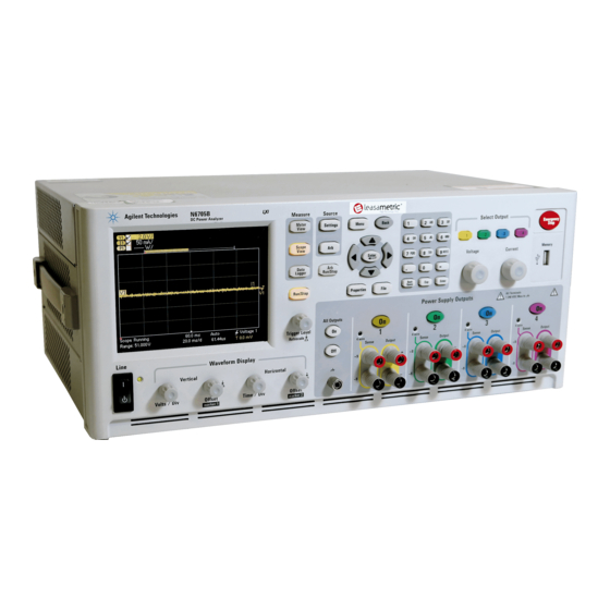
- Page 1 Agilent Technologies DC Power Analyzer Model N6705 User’s Guide ...
- Page 2 Legal Notices Waste Electrical and Assistance Electronic Equipment (WEEE) © Agilent Technologies, Inc. 2007 - 2012 This product comes with the standard Directive 2002/96/EC product warranty. Warranty options, No part of this document may be extended support contacts, product photocopied, reproduced, or translated to...
- Page 3 CAUTION electrical ground (safety ground) at the product. Return the product to an Agilent Denotes a hazard. It calls attention to an power outlet. Any interruption of the Sales and Service Office for service and...
-
Page 4: In This Book
In the United States: (800) 829-4444 In Europe: 31 20 547 2111 In Japan: 0120-421-345 Or use our Web link for information on contacting Agilent in your country or specific location: www.agilent.com/find/assist Or contact your Agilent Technologies Representative. - Page 5 Refer to “Updating the Firmware” in chapter 5 for information on how to update your mainframe with the latest firmware. Note that Agilent N675xA power modules must have Option LGA to support the latest firmware versions. Updated versions of this manual are also posted on the web. Go to www.agilent.com/find/N6705...
-
Page 6: Table Of Contents
Contents 1 - Quick Reference ........................11 The Agilent N6705 DC Power Analyzer – At a Glance ....... 12 Source Features ..................12 Measurement Features ................13 System Features ..................13 Power Module Features ................14 Agilent N678xA Power Module Features ..........15 The Front Panel - At a Glance ................. - Page 7 View Output Ratings ................. 59 Using the Power Supply ................... 60 Controlling the Outputs ................60 Additional Source Settings ..............62 Agilent N678xA SMU Emulation Settings ..........63 Configuring a Turn-On/Turn-Off Sequence .......... 67 Configuring Advanced Properties ............70 Configuring Protection Functions ............72 Configuring Advanced Protection ............
- Page 8 Instrument Calibration ................147 Securing the USB, LAN, and Web Server ........... 148 Restoring the Non-volatile Factory Settings ........148 Disk Management ................... 149 Updating the Firmware ................149 Installing Options ..................150 Changing the Password ................151 Model N6705 User’s Guide...
- Page 9 Dynamic Current Correction Control ............ 172 Measurement System Bandwidth ............173 Averaged Measurements ............... 174 Agilent N6781A and N6782A Current Histogram Measurements .. 175 Measurement Data Formats ..............178 Appendix A - Specifications .....................179 Agilent N6705A, N6705B DC Power Analyzer Mainframe....... 180 Supplemental Characteristics ..............
-
Page 11: Quick Reference
Agilent N6705 DC Power Analyzer. Unless otherwise noted, the Agilent N6705 DC Power Analyzer will also be NOTE referred to as “DC Power Analyzer” throughout this manual. -
Page 12: The Agilent N6705 Dc Power Analyzer - At A Glance
As a multiple-output DC source, the Agilent N6705 provides up to four configurable outputs. Available power modules have power levels of 20 W through 500 W, have various voltage and current combinations, and provide a variety of performance features as described under “Power Module Capabilities”. -
Page 13: Measurement Features
Fast digitizing Available on Agilent N678xA SMU power modules. 5.12 μs/sample for one parameter; 10.24 μs/sample for two parameters. Histogram measurement Available on Agilent N6781A and N6782A SMU power modules. Provides a statistical measurement for profiling the measured current. System Features Choice of three interfaces LAN, USB, and GPIB (IEEE-488) remote programming interfaces are built in Menus let you set up GPIB and LAN parameters from the front panel. -
Page 14: Power Module Features
Option 760 is not available on Models N6741B, N6751A, N6752A, N6761A, and N6762A. Option 2UA is only available on Models N6761A and N6762A. It includes Option 761. Option 055 deletes the Data Logger function on Model N6705. Only available when using the remote interfaces; not from the front panel. -
Page 15: Agilent N678Xa Power Module Features
Arbitrary waveform generation and List capability are not available on the negative current output on Model N6783A. Option 055 deletes the Data Logger function on Model N6705. Only available when using the remote interfaces; not the front panel. Model N6705 User’s Guide... -
Page 16: The Front Panel - At A Glance
Vertical knobs control the vertical size and position. Press Offset to set marker 1. controls Horizontal knobs control the horizontal size and position. Press Offset to set marker 2. The Trigger knob moves the trigger level up or down. Press this knob to autoscale. Model N6705 User’s Guide... -
Page 17: The Rear Panel - At A Glance
Agilent N6781A power modules. connector Wiring access ports Access for sense and output wire connections. Only available on Agilent N6705B mainframes. Used for output connections on power modules rated > 20 A. Also used for Agilent N678xA SMU power modules when extremely precise measurements or output guarding is required. -
Page 18: Meter View
Displays the maximum voltage and current ratings of the output. Also displays the present over-voltage protection setting and whether over-current protection is on or off. Protection Displays the actual voltage, current, and status of the other outputs. Other Outputs Model N6705 User’s Guide... -
Page 19: Scope View
Measurement Marker 2 enabled. Adjust using Marker 2 knob. Press knob to reset. Intersect Point Shows where the measurement markers intersect the waveform. Shows the calculations of the waveform data between Marker 1 and Marker 2. Measurements Model N6705 User’s Guide... -
Page 20: Data Logger
1 Quick Reference Data Logger NOTE Option 055 deletes the Data Logger function on Model N6705. Press Data Logger This key toggles between standard and marker views Standard View Marker View Trace Controls Identifies the voltage or current trace that will be displayed. Dashes (----) indicate that the specified trace is turned off. -
Page 21: Arb Preview
Indicates that the Arb on output 3 repeats three times. Time Indicates the time that the longest Arb will run. In this example, all Arbs run the same amount of time. Close Closes the Arb Preview and returns to the previous measurement view. Model N6705 User’s Guide... -
Page 22: Front Panel Menu Reference
Captures the screen that was active when the File key was pressed. File Management… Accesses additional file functions: New Folder, Delete, Rename, Copy, File Details. Reset/Recall/Power-On State… Resets the instrument to factory defaults; Saves/recalls instrument states; and specifies the power-on turn on state. Model N6705 User’s Guide... - Page 23 A brief overview. Quick Start ► How to quickly get started. Using the Agilent N6705 ► How to use the Agilent N6705. Using the Utilities ► How to use the utilities. Front Panel Controls ► How to use the front panel controls.
-
Page 25: Installation
Agilent N6705 DC Power Analyzer User’s Guide Installation General Information ..................26 Inspecting the Unit ................... 27 Installing the Unit ....................28 Connecting the Line Cord ................33 Connecting the Outputs ................... 33 Connecting the BNC Connectors ..............44 Connecting the Digital Port ................ -
Page 26: General Information
Mainframe Options Description English Manual Set. Contains User’s Guide and Service Guide. Also available as p/n N6705-90000. Japanese Manual Set. Contains User’s Guide and Service Guide. Also available as p/n N6705-90403. Korean Manual Set. Contains User’s Guide and Service Guide. Also available as p/n N6705-90406. -
Page 27: Items Supplied
Inspecting the Unit When you receive your DC Power Analyzer, inspect it for obvious damage that may have occurred during shipment. If there is damage, notify the shipping carrier and nearest Agilent Sales and Support Office immediately. Refer to www.agilent.com/find/assist. -
Page 28: Installing The Unit
Settings key, then press Properties. The power modules are listed under each output channel. Outputs that are not connected to a power module will not be displayed in the Meter view. Model N6705 User’s Guide... -
Page 29: Power Module Installation
Installation 2 Power Module Installation The information in this section applies if you have purchased an N6705 NOTE mainframe without the power modules installed, or if you are adding a power module to the mainframe. Turn the mainframe off and disconnect the power cord before installing or CAUTION removing power modules. - Page 30 Observe the output color code. Tighten all connector screws. An adapter “A” is required to install modules in Agilent N6705A mainframes. For model N6781A, install the auxiliary measurement (Aux Meas) cable.
-
Page 31: High Current Output Connections
High current (50 A) load connections are made using the rear panel access ports of the Agilent N6705B. These access ports have a thin rubber membrane which can be pierced using the load wires. -
Page 32: Bench Installation
Use Rack Mount kit (Option 908 or Option 909 with handles) to rack mount the CAUTION instrument. Installation instructions are provided with the rack mount kit. Agilent N6705 DC Power Analyzer mainframes can be mounted in a 19-inch EIA rack cabinet. They are designed to fit in four rack-units (4U) of space. -
Page 33: Connecting The Line Cord
Connect the power cord to the IEC 320 connector on the rear of the unit. If the wrong power cord was shipped with your unit, contact your nearest Agilent Sales and Support Office. The AC input on the back of your unit is a universal AC input. It accepts nominal line voltages in the range of 100 VAC to 240 VAC. -
Page 34: Wire Size And Length
(refer to the table below). To satisfy safety requirements, load wires must be heavy enough not to overheat while carrying the short- circuit output current of the unit. Agilent Model N678xA SMU wiring requirements are described on the following page. -
Page 35: Agilent N678Xa Smu Wiring Requirements
Because of the effect of wire inductance, the wire length information given in NOTE the previous table does not apply to Agilent Models N678xA SMU. To minimize the effect of wire inductance, the following table describes the allowable load lead and wire length for several common cable types. - Page 36 As shown below, cable guards are available at the internal connector of Agilent Models N678xA SMU. The guard is typically used to drive the shields of cables and test fixtures. It provides a buffered voltage that is at the same potential as the + output terminals of the module connector.
-
Page 37: Multiple Loads
Keep the load leads under 14.7 meters (50 feet) per lead because of inductance effects. Agilent Models N678xA SMU have additional wiring restrictions as discussed under “Agilent N678xA SMU Wiring Requirements”. If load considerations require the use of distribution terminals that... - Page 38 0.5Ω per lead (this requires 20 AWG or heavier for a 50 foot length). Agilent Models N678xA SMU require remote sensing when using any of the High output bandwidth modes discussed in Chapter 6. Also, these models have additional wiring restrictions as discussed under “Agilent N678xA SMU Wiring Requirements”.
- Page 39 OVP circuit could be higher than the voltage being regulated at the load. Note that for Agilent Models N678xA SMU only, the OVP circuit senses at the 4-wire sense terminals rather than at the output terminals.
-
Page 40: Parallel Connections
Parallel Connections Only connect outputs that have identical voltage and current ratings in parallel. CAUTION Agilent Models N678xA SMU cannot be connected in parallel. Connecting outputs in parallel provides a greater current capability than can be obtained from a single output. -
Page 41: Series Connections
Only connect outputs that have identical voltage and current ratings in series. CAUTION Agilent Models N678xA SMU and N6783A–x cannot be connected in series. To prevent reverse currents from damaging the DC Power Analyzer when the load is connected, always turn series-connected outputs on and off together. -
Page 42: Additional Load Considerations
Respo (Current Limit Setting)−(Load Current) Note that programming into an external output capacitor may cause the DC Power Analyzer to briefly enter constant current or constant power operating mode, which adds additional time to the estimation. Model N6705 User’s Guide... - Page 43 The instrument can be operated with any output terminal ± 240 VDC including output voltage from ground. Agilent Models N678xA SMU are optimized for grounding the negative output NOTE terminal. Grounding the positive terminal may result in increased current measurement noise and a reduction in current measurement accuracy.
-
Page 44: Connecting The Bnc Connectors
Step 1. Use the nut driver and remove the hex nut (1) from only one of the BNC connectors. Do not remove the lock washer located behind the hex nut. Step 2. Crimp the ring terminal (2) onto the end of the ground wire. Model N6705 User’s Guide... -
Page 45: Connecting The Digital Port
2. Tighten screws 3. Signal common 4. Digital I/O signals 5. FLT/INH signals 6. Output Couple controls Information on configuring the digital port is found in Appendix C. The electrical characteristics are described in Appendix A. Model N6705 User’s Guide... -
Page 46: Connecting The Auxiliary Voltage Measurement Input
This information applies to Agilent Model N6781A only. The auxiliary voltage measurement input is located on the rear panel of the Agilent N6705B. It is primarily used for battery voltage rundown measurements, but it is also suitable for general purpose DC measurements between ±25 VDC. -
Page 47: Connecting To The Interfaces
GPIB (General Purpose Interface Bus). The following figure illustrates a typical GPIB interface system. If you have not already done so, install the Agilent IO Libraries Suite from the Automation-Ready CD that is shipped with your product. - Page 48 USB-enabled instrument to the USB (Universal Serial Bus). The following figure illustrates a typical USB interface system. If you have not already done so, install the Agilent IO Libraries Suite from the Automation-Ready CD that is shipped with your product.
-
Page 49: Lan Interface
They are typically large, centrally-managed networks with services such as DHCP and DNS servers. If you have not already done so, install the Agilent IO Libraries Suite from the Automation-Ready CD that is shipped with your product. - Page 50 LAN. They are typically small, with no centrally-managed resources. If you have not already done so, install the Agilent IO Libraries Suite from the Automation-Ready CD that is shipped with your product.
-
Page 51: Viewing The Active Lan Status
Either the Restart LAN button must be selected, or the DC Power Analyzer must NOTE be rebooted for any LAN parameter modifications to take effect. You can configure the following items in the LAN Settings window: Model N6705 User’s Guide... - Page 52 Use the numeric/alpha keys to enter letters or numbers. Repeatedly pressing a key cycles through the list of choices. After a short delay the cursor automatically moves to the right. Model N6705 User’s Guide...
- Page 53 Allowed values: 720 - 99999 seconds. Default Resets the LAN settings to the factory-shipped state. These settings are listed at the end of chapter 1. Settings Restart LAN Restarts networking to use the modified configuration settings. Model N6705 User’s Guide...
-
Page 54: Communicating Over The Lan
Communicating Over the LAN Using the Web Server Your Agilent N6705 DC Power Analyzer has a built-in Web server that lets you control it directly from an internet browser on your computer. Up to two simultaneous connections are allowed. With additional connections, performance will be reduced. -
Page 55: Using Telnet
DC Power Analyzer as previously discussed. In an MS-DOS Command Prompt box type: telnet hostname 5024 where hostname is the N6705 hostname or IP address, and 5024 is the instrument’s telnet port. You should get a Telnet session box with a title indicating that you are connected to the DC Power Analyzer. -
Page 57: Using The Source Functions
Appendix B lists all of the SCPI commands that can be used to program the instrument. For complete details on using the SCPI commands, refer to the Programmer’s NOTE Reference Help file included on the Agilent N6705 Product Reference CD. This CD-ROM is shipped along with your instrument. ... -
Page 58: Turning The Unit On
If there are no errors, the instrument responds with +0,"No error". Except for self-test errors, all errors are cleared when you exit the Error Log menu or when power is cycled. Model N6705 User’s Guide... -
Page 59: View Output Ratings
N6705 Service Guide. The Service Guide is included as part of the optional Manual Set (Option 0L1). An electronic copy of the N6705 Service Guide is also included on the N6705 Product Reference CD-ROM. -
Page 60: Using The Power Supply
Using the Power Supply Controlling the Outputs NOTE The figures on the right apply to Agilent Models N678xA SMU. Step 1 – Select an output: Press one of the Select Output keys to select an output to control. The lit key identifies the selected output. All subsequent output-specific front panel commands are sent to the selected output. - Page 61 To set only output 1 to 10.02 V and 1 A: VOLT 10.02,(@1) CURR 1,(@1) To set the output current limit to 1 A for Agilent Models N678xA SMU and N6783A: CURR:LIM 1,(@1) To set the output voltage of all outputs to 10 V: VOLT 10.02,(@1:4)
-
Page 62: Additional Source Settings
To select a lower voltage or current range on output 1, program a value that falls within the range: VOLT:RANG 5,(@1) CURR:RANG 1,(@1) To set the Agilent N6761A turn on preference to current priority: OUTP:PMOD CURR,(@1) To reverse the relay polarity on units with Option 760: OUTP:REL:POL REV,(@1) -
Page 63: Agilent N678Xa Smu Emulation Settings
NOTE The Source Settings window lets you access the specialized operating modes of the Agilent Models N678xA SMU when these power modules are installed. The Emulating dropdown list lets you access the specialized operating modes of the Agilent Models N678xA SMU. Use the navigation keys to select one of the emulating modes. - Page 64 Current Priority mode. Note that the negative voltage limit is fixed at –10 mV. Resistance - This is only available on Agilent Model N6781A. Output resistance programming is primarily used in battery emulation applications, and only applies in Voltage Priority mode. Values are programmed in Ohms, from –40 mΩ...
- Page 65 Using the Source Functions 3 Resistance - This is only available on Agilent Model N6781A. Output resistance programming is primarily used in battery emulation applications, and only applies in Voltage Priority mode. Values are programmed in Ohms, from – 40 mΩ to + 1 Ω.
- Page 66 To set the positive current limit of output 1 to 1 A: CURR:LIM 1,(@1) To set the negative current limit, you must first turn limit coupling (tracking) off. Then set the negative current limit to 0.5 A: CURR:LIM:COUP OFF,(@1) CURR:LIM:NEG 0.5,(@1) Model N6705 User’s Guide...
-
Page 67: Configuring A Turn-On/Turn-Off Sequence
The minimum turn-on delays of the power modules are documented in the Agilent N6700 Modular Power System Family Specifications Guide. Model N6705 User’s Guide... - Page 68 On delay sequence. Use the All Outputs Off key to start the Off delay sequence. The All Outputs On/Off keys will turn ALL outputs on or off, whether they are NOTE configured to participate in an output on/off delay sequence or not. Model N6705 User’s Guide...
- Page 69 OUTP:COUP:CHAN 1,2 OUTP:COUP:DOFF:MODE MAN OUTP:COUP:DOFF .050 To query the delay offset of the slowest power module in the mainframe (the maximum delay offset) in seconds: OUTP:COUP:MAX:DOFF? To turn on two coupled outputs in a sequence: OUTP ON,(@1:2) Model N6705 User’s Guide...
-
Page 70: Configuring Advanced Properties
You can query the minimum voltage slew rate using the VOLT:SLEW? query. Current Slew – This is only available on Agilent Models N678xA SMU operating in Current priority mode. The current slew rate determines the rate at which the current changes to a new setting. - Page 71 Using the Source Functions 3 Output Voltage Bandwidth – This is only available on Agilent Models N678xA SMU. Output voltage bandwidth settings allow you to optimize output response time with capacitive loads. Refer to Chapter 6 under “Output Bandwidth” for more information.
-
Page 72: Configuring Protection Functions
+ field. Level For Agilent Models N678xA SMU, the OVP circuit senses at the 4-wire sense terminals rather than at the output terminals. This allows for more precise over-voltage monitoring directly at the load. Refer to “Over-Voltage Protection Considerations”... - Page 73 Using the Source Functions 3 An over-current protection An over-temperature protection. An oscillation protection. Only applies to Agilent N678xA SMU. A power-fail condition on the AC mains. A positive power limit condition. See chapter 6 for further information. A negative power limit condition. See chapter 6 for further information.
-
Page 74: Configuring Advanced Protection
Prot status. The delay is programmable from 1 to 3600 seconds in 1 second increments. Enable Oscillation Protection - This is only available on Agilent Models N678xA SMU. If open sense leads or capacitive loads outside the allowable range cause the output to oscillate, the oscillation protection function detects the oscillation and latches the output off. -
Page 75: Using The Arbitrary Waveform Generator
DC bias transient generator or an arbitrary waveform generator. The maximum bandwidth is based on the type of power module that is installed. This is documented in the Agilent N6700 Modular Power System Family Specifications Guide. See the note in the beginning of Appendix A. -
Page 76: Configuring Pulse Arbs
Arb value. Specify if the Arb should repeat, either continuously or only for a specified repeat count. A repeat count of 1 runs the Arb once. Select Edit Points to convert the parameters to a User-defined Arb. Model N6705 User’s Guide... - Page 77 1: ARB:FUNC:TYPE VOLT,(@1) ARB:FUNC:SHAP PULS,(@1) ARB:VOLT:PULS:STAR 0,(@1) ARB:VOLT:PULS:TOP 10,(@1) ARB:VOLT:PULS:STAR:TIM .25,(@1) ARB:VOLT:PULS:TOP:TIM .5,(@1) ARB:VOLT:PULS:END:TIM .25,(@1) ARB:TERM:LAST OFF,(@1) To set up the transient trigger system and trigger the Arb: VOLT:MODE ARB,(@1) TRIG:ARB:SOUR BUS OUTP ON,(@1) INIT:TRAN(@1) *TRG Model N6705 User’s Guide...
-
Page 78: Configuring User-Defined Arbs
Specify what happens when the waveform completes – select whether the output returns to the DC value that was in effect before the waveform started, or whether the output should remain at the last Arb value. Model N6705 User’s Guide... - Page 79 Internal:\ specifies the instrument’s internal memory. External:\ specifies the Memory port on the front panel. Select Import to import the file. Select Export to export the file. Model N6705 User’s Guide...
- Page 80 1: ARB:FUNC:TYPE VOLT,(@1) ARB:FUNC:SHAP UDEF,(@1) ARB:VOLT:UDEF:LEV 10,20,30,40,50,(@1) ARB:VOLT:UDEF:DWEL 1,2,3,2,1,(@1) ARB:VOLT:UDEF:BOST 0,0,1,0,0,(@1) ARB:TERM:LAST OFF,(@1) To set up the transient trigger system and trigger the Arb: VOLT:MODE ARB,(@1) TRIG:ARB:SOUR BUS OUTP ON,(@1) INIT:TRAN(@1) *TRG Model N6705 User’s Guide...
-
Page 81: Configuring Constant-Dwell Arbs
You can change the dwell per step of the Arb after it has been imported. When an Arb file is imported, the dwell time specified in the file will be entered in the Dwell per step field. Model N6705 User’s Guide... - Page 82 Arb Run/Stop key selects the front panel Arb Run/Stop key as the trigger source. BNC Trigger In selects the rear trigger input BNC connector as the trigger source. Remote command selects a remote interface command as the trigger source. Model N6705 User’s Guide...
- Page 83 Refer to “Measurement Data Formats” in chapter 6 for more information. To set up the transient trigger system and trigger the CD Arb: VOLT:MODE ARB,(@1) TRIG:ARB:SOUR BUS OUTP ON,(@1) INIT:TRAN(@1) *TRG Model N6705 User’s Guide...
-
Page 84: Configuring An Arb Sequence
The only additional step that you need to program is the Pacing. At the end of the step you must specify if the next step will start when the dwell time has elapsed or when an external trigger is received. Model N6705 User’s Guide... - Page 85 Save and Load buttons. Select the Sequence file type .seq. When loading a sequence, specify the output on which the Sequence will run. When saving a Sequence, specify the output from which you want to save the Sequence. Model N6705 User’s Guide...
- Page 86 The Arb function type (voltage or current) must match the Arb type specified in each sequence step. • Sequence steps must be specified sequentially. The last value in the parameter list is the sequence step number. Model N6705 User’s Guide...
- Page 87 To end the sequence at the last Arb value: ARB:SEQ:TERM:LAST ON,(@1) To make the entire sequence repeat twice: ARB:SEQ:COUN 3,(@1) To set up the transient trigger system and trigger the sequence: VOLT:MODE ARB,(@1) TRIG:ARB:SOUR BUS OUTP ON,(@1) INIT:TRAN(@1) *TRG Model N6705 User’s Guide...
-
Page 88: Arbitrary Waveform Parameters
The parameter setting remains at the last Arb value after the Arb completes. ARB:TERM:LAST ON,(@1) Create a user-defined current or voltage Arb from the present Arb property values: ARB:CURR:CONV (@1) ARB:VOLT:CONV (@1) Repeat the Arb continuously.: ARB:COUN INF,(@1) The number of times the Arb repeats. ARB:COUN 10,(@1) Model N6705 User’s Guide... - Page 89 From the remote interface: The setting before the step: ARB:CURR:STEP:STAR 0,(@1) ARB:VOLT:STEP:STAR 0,(@1) The setting after the step: ARB:CURR:STEP:END 1,(@1) ARB:VOLT:STEP:END 5,(@1) The delay after the trigger is received before the step occurs: ARB:CURR:STEP:STAR:TIM 0.01,(@1) ARB:VOLT:STEP:STAR:TIM 0.01,(@1) Model N6705 User’s Guide...
- Page 90 The delay after the trigger is received but before the ramp starts: ARB:CURR:RAMP:STAR:TIM 0.25,(@1) ARB:VOLT:RAMP:STAR:TIM 0.25,(@1) The time that the output ramps up: ARB:CURR:RAMP:RTIM 0.5,(@1) ARB:VOLT:RAMP:RTIM 0.5,(@1) The time the output remains at the end setting after the ramp: ARB:CURR:RAMP:END:TIM 0.01,(@1) ARB:VOLT:RAMP:END:TIM 0.01,(@1) Model N6705 User’s Guide...
- Page 91 The time to complete all staircase steps: ARB:CURR:TIM 0.2,(@1) ARB:VOLT:TIM 0.2,(@1) The time the output remains at the end setting after the staircase: ARB:CURR:STA:END:TIM 0.2,(@1) ARB:VOLT:STA:END:TIM 0.2,(@1) The total number of staircase steps: ARB:CURR:STA:NST 3,(@1) ARB:VOLT:STA:NST 3,(@1) Model N6705 User’s Guide...
- Page 92 The frequency of the sine wave. From the remote interface: The amplitude or peak value: ARB:CURR:SIN:AMPL 1,(@1) ARB:VOLT:SIN:AMPL 5,(@1) The offset from zero: ARB:CURR:SIN:OFFS 1,(@1) ARB:VOLT:SIN:OFFS 5,(@1) The frequency of the sine wave: ARB:CURR:SIN:FREQ 1,(@1) ARB:VOLT:SIN:FREQ 1,(@1) Model N6705 User’s Guide...
- Page 93 The delay after the trigger is received but before the pulse starts: ARB:CURR:PULS:STAR:TIM 0.25,(@1) ARB:VOLT:PULS:STAR:TIM 0.25,(@1) The width of the pulse: ARB:CURR:PULS:TOP:TIM 0.5,(@1) ARB:VOLT:PULS:TOP:TIM 0.5,(@1) The time the output remains at the end setting after the pulse: ARB:CURR:PULS:END:TIM 0.25,(@1) ARB:VOLT:PULS:END:TIM 0.25,(@1) Model N6705 User’s Guide...
- Page 94 The time that the trapezoid ramps up (RTIM) and down (FTIM): ARB:CURR:TRAP:RTIM 0.5,(@1) ARB:VOLT:TRAP:RTIM 0.5,(@1) ARB:CURR:TRAP:FTIM 0.5,(@1) ARB:VOLT:TRAP:FTIM 0.5,(@1) The width of the peak: ARB:CURR:TRAP:TOP:TIM 1.5,(@1) ARB:VOLT:TRAP:TOP:TIM 1.5,(@1) The time the output remains at the end setting after the trapezoid: ARB:CURR:PULS:END:TIM 0.25,(@1) ARB:VOLT:PULS:END:TIM 0.25,(@1) Model N6705 User’s Guide...
- Page 95 The delay after the trigger is received but before the waveform starts: ARB:CURR:EXP:STAR:TIM 0.25,(@1) ARB:VOLT:EXP:STAR:TIM 0.25,(@1) Time for the amplitude to go from the start setting to the end setting: ARB:CURR:EXP:TIM 0.75,(@1) ARB:VOLT:EXP:TIM 0.75,(@1) The time constant of the curve: ARB:CURR:EXP:TCON 0.1,(@1) ARB:VOLT:EXP:TCON 0.1,(@1) Model N6705 User’s Guide...
- Page 96 The time that the output stays at the steps: ARB:CURR:UDEF:DWEL 1,2,3,2,1,(@1) ARB:VOLT:UDEF:DWEL 1,2,3,2,1,(@1) Generate an external trigger signal at the start of the step (the trigger is generated at the start of step #3): ARB:CURR:UDEF:BOST 0,0,1,0,0,(@1) ARB:VOLT:UDEF:BOST 0,0,1,0,0,(@1) Model N6705 User’s Guide...
- Page 97 The maximum repeat count for CD Arbs is 256. From the remote interface: The dwell time for each step in seconds.: ARB:CURR:CDW:DWEL 0.01,(@1) ARB:VOLT:CDW:DWEL 0.01,(@1) The current or voltage value of ten steps: ARB:CURR:CDW 0.5,1,1.5,2,2.5,3,3.5,4,4.5,5,(@1) ARB:VOLT:CDW 1,2,3,4,5,6,7,8,9,10,(@1) Model N6705 User’s Guide...
- Page 98 16 points. Advanced Lets you edit the common properties that apply to the entire sequence. See “Configure the Common Properties”. Model N6705 User’s Guide...
-
Page 99: Arb Trigger Sources
Press the Arb key, then select the Trigger Source field. Trigger Source: Description: Arb Run/Stop key The front panel Run/Stop key BNC Trigger in The rear trigger input BNC connector Remote Command A remote interface command. Model N6705 User’s Guide... -
Page 100: Arb Triggers
All Arbs are triggered simultaneously. Once configured, the instrument will wait indefinitely for the trigger signal. If the trigger does not occur, and you wish to cancel the arbitrary waveform, press the Arb Run/Stop key to stop the Arb. Model N6705 User’s Guide... - Page 101 If a bit value of 64 is returned in the query, the TRAN_active bit is true, and the Arb has NOT completed. When the TRAN_active bit is false, the Arb has completed. Refer to the N6705 Programmer’s Reference Help file for more information.
-
Page 102: Importing/Exporting User-Defined And Constant-Dwell Arb Data
For constant-dwell Arbs, the data in the VALUE column must match the Arb type; either voltage or current values. Model N6705 User’s Guide... -
Page 103: Using The Measurement Functions
Appendix B lists all of the SCPI commands that can be used to program the instrument. For complete details on using the SCPI commands, refer to the Programmer’s NOTE Reference Help file included on the Agilent N6705 Product Reference CD. This CD-ROM is shipped along with your instrument. ... -
Page 104: Using The Meter Functions
The accuracy of the voltage and current measurements is based on the type of power modules that are documented in the Agilent N6700 Modular Power System installed, as Family Specifications Guide. -
Page 105: Meter Ranges
To specify a voltage or current measurement range: SENS:CURR:RANG <current>, (@1) SENS:VOLT:RANG <voltage>, (@1) The value that you send should be the maximum current that you expect to measure. The instrument selects the range with the best resolution for the value entered. Model N6705 User’s Guide... -
Page 106: Agilent N678Xa Smu Meter-Only Modes
4 Using the Measurement Functions Seamless voltage and current measurement autoranging is available on Agilent Models N6781A and N6782A. This enables a wide dynamic measurement range with no data lost across ranges. Autoranging does not include the 10 μA range, which must be selected manually. - Page 107 Meter View as shown below. Note that both voltage and current meter functions are active in either mode. From the remote interface: To specify voltage measure only: EMUL VMET,(@1) To measure the voltage: MEAS:VOLT?(@1) To specify current measure only: EMUL AMET,(@1) To measure the current: MEAS:CURR?(@1) Model N6705 User’s Guide...
-
Page 108: Agilent N6781A Auxiliary Voltage Measurements
4 Using the Measurement Functions Agilent N6781A Auxiliary Voltage Measurements The following information only applies to Agilent Model N6781A. NOTE The Agilent N6781A has an auxiliary voltage measurement input, whose primary use is for battery voltage rundown measurements. It may also be suitable for other applications including general purpose DC voltage measurements between +/-25 VDC. -
Page 109: Using The Scope Functions
You can configure the Scope View to display voltage or current waveforms for all outputs. Power waveforms can only be displayed on Agilent Models N676xA and N678xA SMU, as these have simultaneous voltage and current measurement capability (see chapter 1, “Power Module Features”). As explained under “Scope Horizontal”, the maximum sampling rate of the scope varies,... - Page 110 • In the Trigger Source dropdown list, select Output ON/Off Key. • In the Mode dropdown list, select Single. • Select the Horizontal button and make sure that the Horizontal Offset Reference is set to Left. Model N6705 User’s Guide...
- Page 111 3 and 4 are “DC Power” modules, which have a slower turn- on ramp. Refer to chapter 1 under “Power Module Features”. From the remote interface: You cannot program the scope from the remote interface. Model N6705 User’s Guide...
-
Page 112: Scope View
Shows the location of the voltage or current trigger level and output. In this example, the voltage trigger level of output 2 is shown. The trigger source and amplitude are shown at the bottom right of the display. Model N6705 User’s Guide... - Page 113 When the time/div. setting is less than 20 ms/division, the scope will sample at its fastest rate, depending on the number of traces selected: 1 trace (Model N678xA SMU only): 5.12 microseconds 1 to 2 traces (all modules): 10.24 microseconds 3 to 4 traces (all modules): 20.48 microseconds Model N6705 User’s Guide...
- Page 114 Calculates the rms value between the marker locations. To view the rms values, you must unselect one of the other measurements in the Scope Marker Properties window. Only 5 measurements may be displayed at a time. Model N6705 User’s Guide...
- Page 115 Scroll down and select Marker options to access the Scope Marker Properties window. Scroll down and select Jump to peak to move the marker to the peak measurement point of the trace. Model N6705 User’s Guide...
-
Page 116: Scope Properties
If no box is checked, no traces will be displayed for that output. Voltage, current, and power traces can be displayed simultaneously only on Agilent Models N676xA and N678xA SMU, as these models have simultaneous voltage and current measurement capability (see chapter 1, “Power Module Features”). -
Page 117: Scope Ranges
”. Dynamic Current Correction Seamless Measurements For Agilent Models N6781A and N6782A only, you can select seamless voltage and current measurements. The Auto selection provides seamless measurement ranging, which results in a wide dynamic range with no data being lost across ranges. Autoranging does not include the 10 μA range, which must be selected manually. -
Page 118: Scope Marker
Select the Preset button to return the Scope View to the power-on display settings. The vertical offset of each trace will be set to a different value. This is to prevent the traces from overlapping. The offset is referenced to the horizontal center line of the grid. Model N6705 User’s Guide... -
Page 119: Using The Data Logger Functions
• Step 0: 10 V; 1 s • Step 1: 20 V; 1 s • Step 2: 30 V; 1 s • Step 3: 40 V; 1 s • Step 4: 50 V; 1 s • Repeat Count: 5 Model N6705 User’s Guide... - Page 120 Press the Properties key to configure the data logger properties: • Leave the default Duration and Sample Period at 30 seconds and 100 milliseconds respectively. • Select the Trigger button and set the trigger source to Arb Run/Stop Key. Model N6705 User’s Guide...
- Page 121 Measurements between the markers are displayed on the bottom of the display. • You can also use the Vertical Volts/Div knob and the Horizontal Time/Div knob to zoom in on any portion of the logged data. Model N6705 User’s Guide...
- Page 122 10 seconds and at 15 seconds from the start trigger of the data log: SENS:DLOG:MARK1 10 SENS:DLOG:MARK2 15 The following commands return either the average, minimum, or maximum values between the marker positions: FETC:DLOG:VOLT? (@1) FETC:DLOG:VOLT:MIN? (@1) FETC:DLOG:VOLT:MAX? (@1) Model N6705 User’s Guide...
-
Page 123: Data Logger View
Ground Reference The ground reference of the trace. Ground references are offset so that they do not overlap. The ground reference offset value is referenced to the horizontal center line of the grid. Model N6705 User’s Guide... - Page 124 Offset Time. The yellow part of the bar represents the data that is visible on the display. The black part represents the offset time. Model N6705 User’s Guide...
- Page 125 Wh (if selected) Calculates the Watt-hours between the marker locations. To view the Watt hours, you must unselect one of the other measurements in the Datalogger Marker Properties window. Only 5 measurements may be displayed at a time. Model N6705 User’s Guide...
- Page 126 Scroll down and select Marker options to access the Datalogger Marker Properties window. Scroll down and select Jump to peak to move the marker to the peak measurement point of the trace. Model N6705 User’s Guide...
-
Page 127: Data Logger Properties
If the file size exceeds the available space on the drive to which it will be written, an error is generated and the Data Logger will not run. From the remote interface: To enable current or voltage data logging on outputs 1 and 2: SENS:DLOG:CURR ON,(@1,2) SENS:DLOG:VOLT ON,(@1,2) Model N6705 User’s Guide... -
Page 128: Data Logger Ranges
”. Dynamic Current Correction Seamless Measurements For Agilent Models N6781A and N6782A only, you can select seamless voltage and current measurements. The Auto selection provides seamless measurement ranging, which results in a wide dynamic range with no data being lost across ranges. Autoranging does not include the 10 μA range, which must be selected manually. -
Page 129: Data Logger Trigger
Trigger Position % of Duration - specifies a trigger offset. This allows the specified percent of pre-trigger data to be logged to the file. The trigger position is expressed as a percentage of the data log duration. Model N6705 User’s Guide... - Page 130 To specify a trigger offset at 25 percent of the duration of the datalog: SENS:DLOG:OFFS 25 To trigger the Data Logger measurement: TRIG:DLOG (@1) (If the trigger source is BUS, you can also program *TRG or <GET>.) Model N6705 User’s Guide...
-
Page 131: Data Logger Filename
Select the Markers button to configure the measurements that appear on the bottom of the display in Marker view. Measurements apply to the portion of the trace between the two markers. You can only select a maximum of five measurements to be displayed. Model N6705 User’s Guide... -
Page 132: Data Logger Preset
In the power-on settings, the vertical offset of each trace is set to a different value. This is to prevent the traces from overlapping. The offset is referenced to the horizontal center line of the grid. Model N6705 User’s Guide... -
Page 133: Data Logger Sampling Modes
Continuously-sampled continuously samples the voltage or current data at about 50 kHz. Both voltage and current can be continuously sampled on Agilent Models N676xA and N678xA SMU. Power is calculated from the instantaneous voltage and current values. Only voltage or current can be continuously sampled on all other power modules. - Page 134 Standard (interleaved) mode only applies when both voltage and current measurement traces are selected on power modules other than Agilent Models N676xA and N678xA SMU. These other power modules cannot measure voltage and current simultaneously; hence, the voltage and current measurements must be interleaved. Each measurement is sampled for about 5 milliseconds at the beginning of every sample period.
-
Page 135: Scope And Data Logger Display Differences
Left, center, or right Does not apply to strip chart trigger offset reference Trace save Press File, select Save Automatically saved to default.dlog file (A different file name can be specified prior to running the datalog.) Model N6705 User’s Guide... -
Page 137: Using The System Functions
Agilent N6705 DC Power Analyzer User’s Guide Using the System Functions Using the File Functions ................138 Configuring User Preferences ............... 145 Using the Administrative Tools ..............147 This chapter contains information about the following system utilities: File functions ... -
Page 138: Using The File Functions
After a brief pause, the cursor will accept the displayed character and move one position to the right. Use Backspace to back up and delete an entry. Use to enter a space. Press Enter when finished. Model N6705 User’s Guide... -
Page 139: Load Function
External:\ specifies the Memory port on the front panel. Enter a name in the text field. See “Enter the File Name” Browse Lets you browse another directory or USB memory device. Export Exports the data to the file name in .csv format. Model N6705 User’s Guide... -
Page 140: Import Function
Lets you browse another directory or USB memory device. Print Friendly Check this box to save Scope View and Data Logger screens with a white instead of a dark background. Create .gif Saves the image to the specified .gif file. Model N6705 User’s Guide... -
Page 141: Show Details
Specifies the file or directory to be deleted. Name Internal:\ specifies the instrument’s internal memory. External:\ specifies the Memory port on the front panel. Browse Lets you browse another directory or USB memory device. Delete Deletes the selected file. Model N6705 User’s Guide... -
Page 142: Rename Function
Specifies a destination directory. Path Internal:\ specifies the instrument’s internal memory. External:\ specifies the Memory port on the front panel. Browse Lets you browse another directory or USB memory device. Copy Copies the selected file to the specified destination. Model N6705 User’s Guide... -
Page 143: New Folder
These functions can also be accessed using the SCPI *SAV and *RCL commands. At Power-On lets you recall the Reset State (*RST), or recall the instrument state stored in location 0. Model N6705 User’s Guide... -
Page 144: Using An External Usb Memory Device
Data is saved in binary format. To export in .csv format you must Load the data NOTE from the USB memory device back into the instrument and Export the data in .csv format as described under “Exporting Data to a Spreadsheet”. Model N6705 User’s Guide... -
Page 145: Configuring User Preferences
Uncheck to enable the voltage and current knobs. Check Enable Front Panel Key Clicks to enable key clicks. Uncheck to disable key clicks. Under Default Meter View, you can specify if the instrument turns on with single-output view or all-outputs view. Model N6705 User’s Guide... -
Page 146: Front Panel Lockout
If the password is lost, the SYSTem:PASSword:FPANel:RESet command can NOTE reset the front panel lockout password. Refer to the Programmer’s Reference Help file on your Agilent N6705 Product Reference CD for more information. Clock Setup When shipped from the factory, the DC Power Analyzer’s clock is set to Greenwich mean time. -
Page 147: Using The Administrative Tools
For complete information about calibrating the instrument, refer to the calibration section in the N6705 Service Guide. The Service Guide is included with the optional Manual Set (Option 0L1). An electronic copy is included on the N6705 Product Reference CD. -
Page 148: Securing The Usb, Lan, And Web Server
To erase all files on the internal drive and restore the factory-shipped settings and the non-volatile settings, log into the Administrative Tools menu. Select Nonvolatile RAM Reset and press the Reset button. Refer to Appendix B for the non-volatile factory settings. Model N6705 User’s Guide... -
Page 149: Disk Management
Click the Browse button and navigate to the firmware file on the External USB memory Device. Press the Install Firmware button to update the firmware. A message will then appear instructing you to reboot the instrument and activate the firmware. Press Reboot or cycle AC power. Model N6705 User’s Guide... -
Page 150: Installing Options
This option is only available on instruments that have been purchased with Option 055 – Delete Data Logger. Agilent 14585A Control and Analysis Software To access the disk management utilities, log into the Administrative Tools menu, then select Install Options. From the dropdown menu, select the option you wish to install and enter the Access Key number from your software license documentation. -
Page 151: Changing The Password
0. If the message “Locked out by internal switch setting” or “Calibration is inhibited by switch setting” appears, the internal switch is set to prevent the password from being changed (Refer to the Service Guide). Model N6705 User’s Guide... -
Page 153: Advanced Source And Measurement Functions
Agilent N6705 DC Power Analyzer User’s Guide Advanced Source and Measurement Functions Source Operating Modes ................154 Advanced Measurements ................162 This chapter discusses the difference between constant voltage and constant current operating modes, multiple output quadrant operation, and other advanced source functions. It also discusses... -
Page 154: Source Operating Modes
All DC power modules, except for Agilent Models N678xA SMU, are designed as constant voltage sources. This means that the specifications and operating characteristics are optimized for constant voltage mode operation. -
Page 155: Autoranging
NOTE The following figure illustrates the autoranging output characteristic of the Agilent N675xA and N676xA power modules. Point 3 shows a situation in which the voltage and current settings are such that the operating locus is limited by the maximum output power boundary of the output. -
Page 156: Power Limit Operation
A status bit (PF) will indicate that a power fault protection event has occurred. For Agilent N678xA SMU, the power limit function does not apply because their maximum output power is rated at 20W. -
Page 157: Output Grouping
To specify a power limit, press the Settings key to access the Source Settings window. Navigate to and select the Advanced button. Output Grouping Output grouping does not apply to Agilent Models N678xA SMU. NOTE Up to four identical outputs can be configured or “grouped” to create a single output with higher current and power capability. -
Page 158: Agilent N678Xa Smu Multi-Quadrant Operation
SYST:REB Agilent N678xA SMU Multi-Quadrant Operation Agilent Models N678xA SMU can be operated in either voltage or current priority mode. They can source as well as sink output power. Note that Agilent Models N6781A and N6782A operate only in the + Voltage quadrants. - Page 159 In current priority mode, the output current should be programmed to the desired positive or negative value. A positive voltage limit value should also be set. The voltage limit should always be set higher than the actual output voltage requirement of the external load. With Model N6705 User’s Guide...
- Page 160 Once the current is exceeds 12% of the rated current of the range (1.12 A on the 1 A range; 3.36 A on the 3 A range), the output will shut down, the output relays will open, and the OC and PROT status bits will be set. Model N6705 User’s Guide...
-
Page 161: Output Bandwidth
50 to 200 mΩ High3 Remote only 6 inches (15 cm) See Chapter 2 under “Agilent N678xA SMU Wiring Requirements” for additional information on allowable load lead lengths. Connecting capacitive loads that fall outside the indicated ranges may result in NOTE output instability or oscillation, and cause the output to turn off, setting the OSC status bit. -
Page 162: Advanced Measurements
Seamless Measurements Seamless voltage and current measurement autoranging is available on Agilent Models N6781A and N6782A. This enables a wide dynamic measurement range with no data lost across ranges. Autoranging does not include the 10 μA range, which must be selected manually. - Page 163 RES20. Values above 20.48 microseconds are rounded to the nearest 40.96-microsecond increment when the resolution is set to RES40. You can change the time interval resolution as follows: SENS:SWE:TINT:RES RES20, (@1) SENS:SWE:POIN:RES RES40, (@1) Model N6705 User’s Guide...
- Page 164 AC line ripple, a Rectangular window can introduce errors when calculating average measurements. This can occur when a non- integral number of cycles of data has been acquired due to the last partial cycle of acquired data. Model N6705 User’s Guide...
- Page 165 LIST:TOUT:EOST 1, (@3) To select a voltage or current level of another output as the trigger for output 1: (Output 3 will generate the voltage or current level to trigger output 1.) TRIG:ACQ:SOUR VOLT3,(@1) TRIG:ACQ:SOUR CURR3,(@1) Model N6705 User’s Guide...
- Page 166 If a bit value of 8 is returned in the query, the WTG_meas bit is true, and the instrument is ready to receive the trigger signal. Refer to the N6705 Programmer’s Reference Help file for more information. It will be necessary to initiate the measurement trigger system each time a NOTE triggered measurement is desired.
- Page 167 If a bit value of 32 is returned in the query, the MEAS_active bit is true, and the measurement is NOT complete. When the MEAS_active bit is false, you can retrieve the measurement. Refer to the N6705 Programmer’s Reference Help file for more information. Use Array queries to return all data from the measurement buffer.
-
Page 168: External Data Logging
Programming the external data logger consists of: Selecting the measurement functions and ranges. Specifying the measurement integration period. Selecting the trigger source. Triggering the data logger. Retrieving the data log measurement. Model N6705 User’s Guide... - Page 169 Seamless Measurements Seamless voltage and current measurement autoranging is available on Agilent Models N6781A and N6782A. This enables a wide dynamic measurement range with no data lost across ranges. Autoranging does not include the 10 μA range, which must be selected manually.
- Page 170 PIN<n> Selects a pin on the digital port. <n> specifies the pin number. The pin must be configured as a Trigger Input to be used as a trigger source (see Appendix C). Model N6705 User’s Guide...
- Page 171 Binary data is returned as a comma-separated list of data for each channel requested. The data for each channel is a definite length binary block, with the byte order specified by the FORMat:BORDer command. Terminate the Measurement To abort the external data logger: ABOR:ELOG (@1) Model N6705 User’s Guide...
-
Page 172: Dynamic Current Correction Control
To turn dynamic current correction on or off, press Scope View or Data Logger , then press Properties . In the current range dropdown box, select the range labeled “CComp On” to turn current correction on. Un-select the “CComp On” range to turn current correction off. Model N6705 User’s Guide... -
Page 173: Measurement System Bandwidth
NOTE making static (or DC) measurements. This information does not apply to models N678xA SMU. For N678xA bandwidth information, refer to the Agilent N6700 Modular Power System Family Specifications Guide. The measurement bandwidth of the DC Power Analyzer is dependent on the following factors: Whether voltage or current is being measured. -
Page 174: Averaged Measurements
3.52 µF N6776A, N6777A 3.54 µF For example, if you are measuring the output current on an Agilent N6731B with a 10 ohm load connected to the output, and with dynamic current correction turned off, the largest frequency that can be measured without introducing measurement errors is 530 Hz. -
Page 175: Agilent N6781A And N6782A Current Histogram Measurements
Advanced Source and Measurement Functions 6 Agilent N6781A and N6782A Current Histogram Measurements The following information only applies to Agilent Models N6781A and N6782A. NOTE Histogram measurements are not available if option 055 (delete data logger) has been ordered. A current histogram measurement provides a statistical measurement for profiling the measured current. - Page 176 6 Advanced Source and Measurement Functions Seamless Measurements For Agilent Models N6781A and N6782A only, you can select seamless voltage and current measurements. The Auto selection provides seamless measurement ranging, which results in a wide dynamic range with no data being lost across ranges. Autoranging does not include the 10 μA range, which must be selected manually.
- Page 177 4096 counts returned by FETC:HIST:CURR? Because the current measurements can be positive or negative, bin 0 represents the most negative current, bin 2048 represents 0, and bin 4095 is the most positive current. Model N6705 User’s Guide...
-
Page 178: Measurement Data Formats
(little-endian). The following command specifies the byte order of the data: FORM:BORD NORM | SWAP Use swapped format if you are using a little-endian data processor. Model N6705 User’s Guide... -
Page 179: Appendix A Specifications
NOTE power modules are included in the Agilent N6700 Modular Power System Family Specifications Guide. This document is available on the Agilent N6705 Product Reference CD that is shipped along with your instrument as well as on the web at www.agilent.com/find/N6705. -
Page 180: Agilent N6705A, N6705B Dc Power Analyzer Mainframe
SCPI - 1993, IEEE 488.2 compliant interface LXI Compliance Class C USB 2.0 Requires Agilent IO Library version M.01.01 or 14.0 and up 10/100 LAN Requires Agilent IO Library version L.01.01 or 14.0 and up Built-in Web server Requires Internet Explorer 7+ or Firefox 2+... - Page 181 0.99 @ nominal input and rated power NOTE 1 Fuse Internal fuse - not customer accessible. Net Weight: N6705 with 4 modules (typical) 16 kg / 35 lbs Single power module (typical) 1.23 kg / 2.71 lbs Dimensions: Refer to the outline diagrams on the following page.
-
Page 182: Outline Diagram
Appendix A Specifications Outline Diagram 272.6 mm 10.733 in. = airflow 16.9 mm 0.663 in. 425.6 mm 16.756 in. 23.5 mm 0.923 in. 177.0 mm 17.7 mm 6.968 in. 0.697 in. Model N6705 User’s Guide... -
Page 183: Appendix B - Scpi Commands And Instrument Settings
Agilent N6705 DC Power Analyzer. For complete details on programming the instrument using SCPI commands, NOTE refer to the Programmer’s Reference Help file included on the Agilent N6705 Product Reference CD. This CD-ROM is shipped along with your instrument. ... -
Page 184: Scpi Command Summary
Returns the high level of a current pulse :LOW? (@chanlist) Returns the low level of a current pulse :MAXimum? (@chanlist) Returns the maximum current :MINimum? (@chanlist) Returns the minimum current :POWer [:DC]? (@chanlist) Returns the average output power Model N6705 User’s Guide... - Page 185 Takes a measurement; returns the high level of a current pulse :LOW? (@chanlist) Takes a measurement; returns the low level of a current pulse :MAXimum? (@chanlist) Takes a measurement; returns the maximum current :MINimum? (@chanlist) Takes a measurement; returns the minimum current Model N6705 User’s Guide...
- Page 186 :OSCillation[:STATe] <Bool>, (@chanlist) Enables/disables output oscillation protection (N678xA SMU) :WDOG [:STATe] <Bool> Enables/disables the I/O watchdog timer :DELay <NRf+> Sets watchdog timer delay :RELay :POLarity NORMal | REVerse, (@chanlist) Sets the output relay polarity (only on option 760) Model N6705 User’s Guide...
- Page 187 Queries the weight of the histogram (N6781A, N6782A) :RANGes? (@chanlist) Queries the values of the bin ranges (N6781A, N6782A) [:DC]:RANGe [:UPPer] <NRf+>, (@chanlist) Sets the measurement range of the histogram (N6781A, N6782A) :AUTO <Bool>, (@chanlist) Enables/disables measurement autoranging (N6781A, N6782A) Model N6705 User’s Guide...
- Page 188 Sets the length of the start time or delay :SINusoid :AMPLitude < NRf+>, (@chanlist) Sets the amplitude of the sine wave :FREQuency < NRf+>, (@chanlist) Sets the frequency of the sine wave :OFFSet < NRf+>, (@chanlist) Sets the DC offset of the sine wave Model N6705 User’s Guide...
- Page 189 Specifies the type of pacing for the step :VOLTage <ARB_function>, <step#>, (@chanlist) Programs the waveform steps within a voltage sequence :TERMinate :LAST <Bool>, (@chanlist) Sets the sequence termination mode :TERMinate:LAST <Bool>, (@chanlist) Sets the Arb termination mode Model N6705 User’s Guide...
- Page 190 Specifies how the list responds to triggers :TERMinate :LAST <Bool>, (@chanlist) Sets the list termination mode :TOUTput :BOSTep [:DATA] <Bool> {,<Bool>}, (@chanlist) Generate triggers at the Beginning Of STep :POINts? (@chanlist) Returns the number of BOST list points Model N6705 User’s Guide...
- Page 191 Returns the value of the operation condition register :ENABle <NRf>, (@chanlist) Enables specific bits in the event register :NTRansition <NRf>, (@chanlist) Sets the negative transition filter :PTRansition <NRf>, (@chanlist) Sets the positive transition filter :PRESet Presets all enable and transition registers to power-on Model N6705 User’s Guide...
- Page 192 Sets the internal data logger trigger source <source> = BUS, CURRent<n>, EXTernal, IMMediate, VOLTage<n>, ARSK, OOOK :VOLTage [:LEVel] <NRf>, (@chanlist) Sets the voltage trigger level of the data logger :SLOPe POSitive | NEGative, (@chanlist) Sets the voltage trigger slope of the data logger Model N6705 User’s Guide...
-
Page 193: Common Commands
Digital port polarity (all pins) Positive Screen saver Enabled Front panel lockout Disabled Screen saver delay 60 minutes Front panel meter view Single-channel USB interface Enabled GPIB Address Wake on I/O Enabled Key clicks Enabled Web server Enabled Model N6705 User’s Guide... -
Page 194: Power-On Settings
VOLT ARB:CURRent|VOLTage:STAircase:STAR:TIMe FORMat:DATA ASCII ARB:CURRent|VOLTage:STAircase:TIMe FORMat:BORDer NORM ARB:CURRent|VOLTage:STEP:END INITiate:CONTinuous:TRANsient ARB:CURRent|VOLTage:STEP:STARt LIST:COUNt ARB:CURRent|VOLTage:STEP:STARt:TIMe LIST:CURRent ARB:CURRent|VOLTage:TRAPezoid:END:TIMe LIST:DWELl 0.001 ARB:CURRent|VOLTage:TRAPezoid:FTIMe LIST:STEP AUTO ARB:CURRent|VOLTage:TRAPezoid:RTIMe LIST:TERMinate:LAST ARB:CURRent|VOLTage:TRAPezoid:STARt LIST:TOUTput:BOST ARB:CURRent|VOLTage:TRAPezoid:STARt:TIMe LIST:TOUTput:EOST ARB:CURRent|VOLTage:TRAPezoid:TOP LIST:VOLTage ARB:CURRent|VOLTage:TRAPezoid:TOP:TIMe OUTPut ARB:CURRent|VOLTage:UDEFined:BOSTep OUTPut:COUPle ARB:CURRent|VOLTage:UDEFined:DWELl 0.001 OUTPut:DELay:FALL ARB:CURRent|VOLTage:UDEFined:LEVel OUTPut:DELay:RISE Model N6705 User’s Guide... - Page 195 TRIGger:DLOG:VOLTage:SLOPe SENSe:DLOG:VOLTage:RANGe:AUTO TRIGger:ELOG:SOURce SENSe:ELOG:CURRent:RANGe:AUTO TRIGger:HISTogram:SOURce SENSe:ELOG:FUNCtion:CURRent TRIGger:TRANsient:SOURce SENSe:ELOG:FUNCtion:CURRent:MINMax VOLTage SENSe:ELOG:FUNCtion:VOLTage VOLTage:BWIDth SENSe:ELOG:FUNCtion:VOLTage: MINMax VOLTage:LIMit SENSe:ELOG:PERiod VOLTage:LIMit:COUPle SENSe:ELOG:VOLTage:RANGe:AUTO VOLTage:LIMit:NEGative SENSe:FUNCtion “VOLT” VOLTage:MODE SENSe:FUNCtion:CURRent VOLTage:PROTection:DELay SENSe:FUNCtion:VOLTage VOLTage:PROTection:REMote SENSe:FUNCtion:VOLTage:INPut MAIN VOLTage:PROTection:REMote:NEGative SENSe:HISTogram:CURRent:RANGe VOLTage:RANGe SENSe:HISTogram:CURRent:RANGe:AUTO VOLTage:SLEW 9.9E+37 SENSe:HISTogram:FUNCtion:CURRent VOLTage:SLEW:MAX VOLTage:TRIGger Model N6705 User’s Guide...
-
Page 196: Agilent N678Xa Smu Initial Emulation Mode Settings
Appendix B SCPI Commands Agilent N678xA SMU Initial Emulation Mode Settings The following tables document the emulation mode settings that are applied when the emulation mode is selected. Emulation mode settings are not saved. 4 Quadrant Power 2 Quadrant Power... -
Page 197: Appendix C Using The Digital Port
Agilent N6705 DC Power Analyzer User’s Guide Appendix C Using the Digital Port Configuring the Digital Port ................198 A Digital Control Port consisting of seven I/O pins is provided to access various control functions. Each pin is user-configurable. The... -
Page 198: Configuring The Digital Port
Digital Output Pins 1 - 7 TTL, AS, CMOS, HC Relay driver Pins 1 - 7 (contain internal clamp diodes for inductive flyback) Digital Input Pins 1 - 7 A) Relay Circuits B) Digital Interface Circuits Model N6705 User’s Guide... - Page 199 To configure the pin polarity to positive for pins 1 through 4: DIG:PIN1:POL POS DIG:PIN2:POL POS DIG:PIN3:POL POS DIG:PIN4:POL POS To send a binary weighted value to configure pins 1 through 7 as “0000111”: DIG:OUTP:DATA 7 Model N6705 User’s Guide...
-
Page 200: Digital Input
Pin 2’s selected function is ignored. The Fault output signal will remain latched until the fault condition is removed and the protection circuit is cleared (see chapter 3, “Configuring Protection Functions”). Model N6705 User’s Guide... -
Page 201: Inhibit Input
Select pin 3 from the Pin dropdown list. Select the Inhibit In function for the pin the from the Function dropdown list. Configure the polarity for the pin by selecting the Polarity dropdown menu. Select either Positive or Negative. Model N6705 User’s Guide... -
Page 202: Fault/Inhibit Operating Mode
The Inhibit input is ignored. From the remote interface: To latch the Inhibit signal, send: OUTP:INH:MODE LATC To set the Inhibit signal live, send: OUTP:INH:MODE LIVE To disable the Inhibit signal, send: OUTP:INH:MODE OFF Model N6705 User’s Guide... -
Page 203: Fault/Inhibit System Protection
To re-enable the chain, re-program the Inhibit input on each mainframe to Latched mode. Trigger Input Any of the Digital Control pins can be programmed to function as a trigger input. All pins are referenced to the Signal Common pin. Model N6705 User’s Guide... -
Page 204: Trigger Output
User-defined arbitrary waveform (see chapter 3), an output trigger signal will be generated on the configured digital pin as well as on the BNC trigger output connector at the start of the voltage or current step. Model N6705 User’s Guide... -
Page 205: Output Couple Controls
3. Connect and configure the digital connector pins of the synchronized mainframes as described in this section. All synchronized N6705 mainframes must have the same firmware revision. NOTE Only pins 4 through 7 can be configured as synchronization pins. You cannot configure more than one On Couple and one Off Couple pin per mainframe. - Page 206 SCPI commands. Turning the outputs on or off using the front panel All Outputs On and Off keys will cause all coupled outputs as well as non-coupled outputs on that mainframe to turn on or off. Model N6705 User’s Guide...
- Page 207 ............30, 46 initiate ................166 digital port ..............45 pre-trigger data ............164 external trigger ............17, 44 returning data .............. 167 guard ................36 sample interval ............163 high current ..............31 trigger source ............... 165 Model N6705 User’s Guide...
- Page 208 400 Hz .............. 32 settings ................51 front panel site ................... 49 controls ................16 sockets ................55 descriptions ..............16 status ................51 display ................18 telnet ................55 key lockout ..............146 latched ................202 Model N6705 User’s Guide...
- Page 209 RAM reset ..........148 power limit ..............70, 156 non-volatile settings ............193 power module normal sampling .............. 134 location ................28 notice power module installation ..........29 legal ................... 2 power receptacle ..............3 safety ................. 3 power-on Model N6705 User’s Guide...
- Page 210 ............74 screen capture ..............140 Web server sense connection ..............54 4-wire ................ 37, 70 Web URL’s ................4 local ................. 70 WEEE directive ..............2 open ................. 39 wire sizes ................34 Model N6705 User’s Guide...