Festo CAMC-G-S3 Manual
Safety module
Hide thumbs
Also See for CAMC-G-S3:
- Translation of the original instructions (24 pages) ,
- Instructions | safety function, advanced safety (4 pages) ,
- Translation of the original instructions (4 pages)

Subscribe to Our Youtube Channel
Related Manuals for Festo CAMC-G-S3


Summary of Contents for Festo CAMC-G-S3
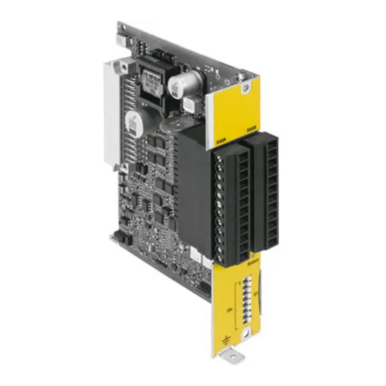
- Page 1 Safety module CAMC-G-S3 Description Safety functions – STO, – SS1, – SS2, – SOS, – SBC, – SLS, – SSR, – SSM in accordance with EN 61800-5-2 for motor controller CMMP-AS-...-M3 759296 1406NH...
- Page 2 Essential or useful accessories. Information on environmentally sound usage. Text designations: • Activities that may be carried out in any order. 1. Activities that should be carried out in the order stated. – General lists. Festo – GDCP-CAMC-G-S3-EN – 1406NH – English...
-
Page 3: Table Of Contents
......2.4.3 Single-channel (partially-safe) digital inputs DIN44 … DIN49 [X40] ..Festo – GDCP-CAMC-G-S3-EN – 1406NH – English... - Page 4 ............. Festo – GDCP-CAMC-G-S3-EN – 1406NH – English...
- Page 5 ..........Festo – GDCP-CAMC-G-S3-EN – 1406NH – English...
- Page 6 ..........Diagnostic messages with instructions for fault clearance ......Festo – GDCP-CAMC-G-S3-EN – 1406NH – English...
- Page 7 Status signals via fieldbus – protocol FHPP ......Festo – GDCP-CAMC-G-S3-EN – 1406NH – English...
- Page 8 Terms for the SafetyTool and for safe parameterisation ......Festo – GDCP-CAMC-G-S3-EN – 1406NH – English...
- Page 9 – SSM – Safe Speed Monitor – SBC – Safe Brake Control in accordance with EN 61800-5-2 through the usage of the safety module CAMC-G-S3 for the motor controller CMMP-AS-...-M3. • In addition, always observe the general safety regulations for the CMMP-AS-…-M3.
- Page 10 CAMC-G-S3 Service Please consult your regional Festo contact if you have any technical problems. Issue status of the specified standards Standard: Issue status EN 50178:1997 EN ISO 13849-1:2008 EN 61326-3-1:2008 EN ISO 13849-2:2012 EN 61800-3:2004 + A1:2012 EN 62061:2005 EN 61800-5-1:2007...
-
Page 11: Table Of Contents - Camc-G-S3
User interface and functions of the SafetyTools for paramet erisation of the safety module CAMC-G-S3. Tab. 3 Documentation on the motor controller CMMP-AS-...-M3 The documentation is available on the following media: – CD-ROM (scope of delivery) – Support Portal: è www.festo.com/sp Festo – GDCP-CAMC-G-S3-EN – 1406NH – English... - Page 12 SOS – Safe Operating Stop SSM – Safe Speed Monitor SBC – Safe Brake Control ALF – Advanced Logic Function, not a safety function (Advanced Logic Function) Tab. 4 Safety engineering systems symbols Festo – GDCP-CAMC-G-S3-EN – 1406NH – English...
-
Page 13: Safety And Requirements For Product Use
• Observe the specifications for handling electrostatically sensitive devices. 1.1.2 Intended use The safety module CAMC-G-S3 serves as an expansion of the motor controller CMMP-AS-...-M3 to im plement the safety function: – STO – Safe Torque Off – SS1 – Safe Stop 1 –... -
Page 14: Foreseeable Misuse
– within the product's limits as defined by the technical data è Appendix A.1, – in an industrial environment. The safety module CAMC-G-S3 can be operated in all motor controllers CMMP-AS-...-M3 that have an Ext3 slot for safety equipment. It cannot be plugged into one of the Ext1 or Ext2 slots for interfaces. -
Page 15: Achievable Safety Level
è Section 2.2.5, Tab. 2.7. You can find information on the characteristic safety values, which can be implemented with the corresponding peripherals, for the different safety functions in è Appendix A.2 Festo – GDCP-CAMC-G-S3-EN – 1406NH – English... -
Page 16: Requirements For Product Use
• For emergency stop applications, protection from automatic restart corresponding to the required category must be planned. This can be achieved, for example, with an external safety switching device or suitable parameterisation of the safety module CAMC-G-S3 è Section 2.7. 1.2.1... -
Page 17: Range Of Application And Certifications
“Technical data” è Appendix A.1. The product-relevant EC directives and stand ards can be found in the declaration of conformity. Certificates and declaration of conformity on this product can be found at è www.festo.com/sp. Festo – GDCP-CAMC-G-S3-EN – 1406NH – English... -
Page 18: Product Description Of Safety Module Camc-G-S3
In such situations, the machine operator must be protec ted by drive and internal control measures. The functional safety engineering integrated with the safety module CAMC-G-S3 in the motor controller CMMP-AS-...-M3 meets the requirements of the controller and drive for optimised implementation of protective functions. -
Page 19: Supported Devices
2.1.3 Supported devices The safety module CAMC-G-S3 can only be used in motor controllers in conformity with section 1.1.2. The motor controllers CMMP-AS-...-M3 are delivered without a safety or micro switch module in slot Ext3 for safety modules. -
Page 20: Operating Elements And Connections
Product description of safety module CAMC-G-S3 2.1.4 Operating elements and connections The safety module CAMC-G-S3 has the following control sections, connections and display components: Pin 1 Pin 13 Pin 12 Pin 24 Motor controller CMMP-AS-...-M3 with slot I/O interface [X40A] and [X40B] to control the... -
Page 21: Function And Application
– motor controller CMMP-AS-...-M3, – safety module CAMC-G-S3, – synchronous servo motor, e.g. from the series EMMS-AS or EMME-AS from Festo, – linear axle with second measuring system, e.g. EGC-...-M... from Festo, – reliable clamping unit. Motor... - Page 22 – The safety functions in the CAMC-G-S3 are requested or activated via the digital safe inputs on the safety module, by other safety functions or as an error response. Logic operations can be used to set which digital inputs in which signal combination request a safety function.
-
Page 23: Circuitry Of The Safety Module [X40]
– 3 digital, two-channel outputs (SIL3) with configurable allocation, optionally useable as clock output, – 1 acknowledgment contact (relay contact) for diagnostic purposes, – reference potential for all inputs and outputs, – a 24 V auxiliary current supply for connected sensors. Festo – GDCP-CAMC-G-S3-EN – 1406NH – English... - Page 24 (24 V DC logic supply of the motor controller). 1) Function in the delivery status or after resetting to factory settings (advance parameterisation) Tab. 2.3 Digital inputs and outputs, signal contact, reference potential and auxiliary supply [X40] Festo – GDCP-CAMC-G-S3-EN – 1406NH – English...
-
Page 25: Overview Of The Supported Safety Functions
Safe speed range è Section 2.5.9 SSM Safely monitored speed è Section 2.5.9 Safe brake control è Section 2.5.2 1) A slow movement within the monitored position window can be permissible Tab. 2.4 Equipment of the safety module Festo – GDCP-CAMC-G-S3-EN – 1406NH – English... -
Page 26: Functional Diagram Of The Safety Module
Product description of safety module CAMC-G-S3 2.2.4 Functional diagram of the safety module The functions of the safety module are explained using the following functional diagram: Fig. 2.3 Functional diagram, safety module (legendè Tab. 2.5) Festo – GDCP-CAMC-G-S3-EN – 1406NH – English... - Page 27 Between them is a structure with logic blocks and the safety functions. In the functional diagrams and other block diagrams, all the safe signals have a yellow background and potentially unsafe signals have a grey background. Festo – GDCP-CAMC-G-S3-EN – 1406NH – English...
- Page 28 The following example uses two of the 32 product terms to request the STO function: The product terms are managed automatically using the SafetyTool (a special software, integrated in the FCT PlugIn) and are scarcely visible to the user. Festo – GDCP-CAMC-G-S3-EN – 1406NH – English...
- Page 29 The most important VOUT signals are therefore guided back to logical inputs LIN and are available to logical operations. List of logical inputs è Section B.1.1, Tab. B.2. Festo – GDCP-CAMC-G-S3-EN – 1406NH – English...
-
Page 30: Overview Of Supported Position Encoders
For this reason, safe analysis of the absolute position of the encoders or safe homing is not intended. Each microcontroller on the safety module can analyse up to two position transmitters: Festo – GDCP-CAMC-G-S3-EN – 1406NH – English... - Page 31 2, with error triggering in the case of impermissible deviations. – In each configuration, the two microcontrollers, 1 and 2, use various position and speed values to monitor the axle. In addition, acceleration monitoring can also be configured for a plausibility check. Festo – GDCP-CAMC-G-S3-EN – 1406NH – English...
- Page 32 The manufacturers of SIL-certified shaft encoders publish instructions for the use of these shaft encoders in safety applications. The CAMC-G-S3 takes the following manufacturer specifications into account when evalu ating the encoder signals: – Specification of the E/E/PES safety requirements for EnDat-Master dated 19.10.2009 (D533095 - 04 - G - 01) è...
-
Page 33: Data Exchange And Control Of The Motor Controller
The power output stage of the motor controller can be switched off using two independent channels. One channel controls power connected to the top switch and the other the power connected to the bottom switch. The channels are controlled diversely by the safety module and are continuously Festo – GDCP-CAMC-G-S3-EN – 1406NH – English... - Page 34 The safety module is parameterised using the SafetyTool (è Sections 2.2.7 and 4.5). The SafetyTool is opened via the Festo Configuration Tool (FCT). Secure communication between the SafetyTool and the safety module is optionally ensured via one of the interfaces of the motor con...
- Page 35 – to analyse the status variables of the safety module via the oscilloscope function (Trace). For example, the monitored speed limits and the current speed can be recorded to test why the safety module has detected a violation of a safety condition. Festo – GDCP-CAMC-G-S3-EN – 1406NH – English...
-
Page 36: Configuration Of The Safety Functions With The Safetytool
As measures to ensure the required functional safety are required during the commis sioning phase of a system, note that: • The safety module must be fully configured and the application must be fully valid ated before it can provide any protection Festo – GDCP-CAMC-G-S3-EN – 1406NH – English... -
Page 37: Data Transfer From The Motor Controller
If previously-configured safe motion functions exist in the safety module, then the limit values set in the safety module are transferred to the SafetyTool as setpoints. They must be transmitted to the safety module again, so that the limit values remain un changed. Festo – GDCP-CAMC-G-S3-EN – 1406NH – English... -
Page 38: Basic Information
(without gear ratios). P06.41 Number of digits displayed after the Number of digits displayed after the decimal decimal point for positions. point for position values. Festo – GDCP-CAMC-G-S3-EN – 1406NH – English... - Page 39 Numerator, total gear ratio between motor and motor and axle. axle. P06.4B Denominator, total gear ratio between Denominator, total gear ratio between motor and motor and axle. axle. Tab. 2.8 Parameters for basic information Festo – GDCP-CAMC-G-S3-EN – 1406NH – English...
-
Page 40: Configuration Of The Encoders
1 and as position encoder 2. Gear units between motor and axle are mapped via the gear ratio. Via negative gear factors, a rotational direction reversal is taken into account. Festo – GDCP-CAMC-G-S3-EN – 1406NH – English... -
Page 41: Parameters For The Position Encoder
CMMP-AS-...-M3, run internally to the safety module and then analysed safely and via two channels there by both microcontrollers. Parameterised / data transfer from the basic unit is not required. Festo – GDCP-CAMC-G-S3-EN – 1406NH – English... - Page 42 Please note The use of encoders with purely digital data transmission in safety systems in only per missible in conjunction with a second encoder, e.g. at [X10]. Festo – GDCP-CAMC-G-S3-EN – 1406NH – English...
-
Page 43: Parameter For Encoder Monitoring And Rotational Speed Measuring
Speed 1 / 2 Comparator Sensor 2 POSITION + & SPEED VALID μC1-μC2 Position Comparator [56-9] Sensor μC1-μC2 Speed Comparator Speed + Position from 2nd μC Fig. 2.5 Calculation of the speed and acceleration Festo – GDCP-CAMC-G-S3-EN – 1406NH – English... - Page 44 They should only be changed when required, as they influence the reaction time of the safety module when dangerous movements are detected or during error detection. They are so-called “Expert parameters”. Festo – GDCP-CAMC-G-S3-EN – 1406NH – English...
- Page 45 Influence of the parameters for the encoder configuration on the runtime performance Some configuration parameters for detecting safe rotational speed influence the reaction time, with which changes in the movement are detected. The following parameters have an influence: Festo – GDCP-CAMC-G-S3-EN – 1406NH – English...
-
Page 46: List Of All Parameters For Encoder Configuration
Allowable time for faulty encoder com Allowable time for faulty encoder communication munication P06.18 Number of incr./rev. of the incremental Number of increments / revolution of the incre encoder at X10 mental encoder at X10 Festo – GDCP-CAMC-G-S3-EN – 1406NH – English... - Page 47 P06.15 Filter time, resolver analysis Filter time for the observer filter P06.1C SIN/COS signal amplitude - lower error Min. input voltage, sine or cosine signal limit Festo – GDCP-CAMC-G-S3-EN – 1406NH – English...
-
Page 48: Digital Inputs
A safe input consists of two control cables, which both switch HIGH or LOW signals against one another. At any time (with the exception of the discrepancy time) only one input is simultaneously HIGH or LOW (unequally-switching inputs). Tab. 2.12 Terms Festo – GDCP-CAMC-G-S3-EN – 1406NH – English... - Page 49 The emergency stop switching device is usually used to trigger an emergency stop. In most cases, the safety function STO or SS1 is activated. Door contact switch This monitors whether a safety door, a light curtain, or similar is opened / passed through. Festo – GDCP-CAMC-G-S3-EN – 1406NH – English...
- Page 50 – Now, Emergency Stop is cancelled and the door remains open. => When the Restart button is actuated, the system remains idling with the SS2 safety function active and can restart immediately when the safety door is closed. Festo – GDCP-CAMC-G-S3-EN – 1406NH – English...
- Page 51 Cross-circuits and shorts to +24 V and 0 V through the lack of the test pulses Approved sensor types Tab. 2.14 shows an overview of the approved sensor types at the digital inputs. Festo – GDCP-CAMC-G-S3-EN – 1406NH – English...
- Page 52 1) Factory setting (information on the factory setting and delivery status è Section 4.4.1 and 4.4.2) 2) On activating the logic function in the SafetyTool, the corresponding inputs must be configured accordingly. Tab. 2.14 Overview approved sensor types at the digital inputs Festo – GDCP-CAMC-G-S3-EN – 1406NH – English...
-
Page 53: Two-Channel Safe Inputs Din40
Tab. 2.15 Legend for Fig. 2.6 The signal levels at the inputs DIN40A and DIN40B are first dejammed in a preliminary EMC filter, (“Glitch Filter”). The filter time constant is 500 μs and cannot be parameterised. Festo – GDCP-CAMC-G-S3-EN – 1406NH – English... - Page 54 Status LIN_D40 / … /43 Tab. 2.17 Inputs switching antivalently Passive sensors, which trigger an emergency stop of the system (STO, SBC, SS1), must, according to EN 60204-1, have “forced opening” and be parameterised as equivalent inputs. Festo – GDCP-CAMC-G-S3-EN – 1406NH – English...
- Page 55 DIN40A P02.07 DIN40B P02.07 Ts < 2.5 ms Ts < 2.5 ms P02.04 LIN_D40 P02.08 = 1 P02.08 = 0 Fig. 2.7 Timing diagram of two-channel equivalent safe input – Start request (DIN40) Festo – GDCP-CAMC-G-S3-EN – 1406NH – English...
- Page 56 Timing diagram of two-channel equivalent safe input – Terminate request (DIN40) Term/abbreviation Explanation RSF: Request Safety Function Request safety function CSF: Release Safety Function request Terminate the safety function request Error Discrepancy Discrepancy error Tab. 2.18 Legend for Fig. 2.7 and Fig. 2.8 Festo – GDCP-CAMC-G-S3-EN – 1406NH – English...
- Page 57 Fig. 2.10 Timing diagram of two-channel antivalent safe input – Terminate request (DIN40) Term/abbreviation Explanation RSF: Request Safety Function Request safety function CSF: Release Safety Function request Terminate the safety function request Error Discrepancy Discrepancy error Tab. 2.19 Legend for Fig. 2.9 and Fig. 2.10 Festo – GDCP-CAMC-G-S3-EN – 1406NH – English...
- Page 58 Tab. 2.21 Parameters, two-channel digital inputs Tab. A.10 è in Appendix A.1 describes the technical data for the control ports within the specified operating range of the logic voltages in accordance with EN 61131-1. Festo – GDCP-CAMC-G-S3-EN – 1406NH – English...
-
Page 59: Single-Channel (Partially-Safe) Digital Inputs Din44
DIN44. The inputs DIN44 to DIN49 have an identical structure. DIN44 ... DIN49 GLITCH DIN44/45/... COMPA- FILTER LIN_D44/45/... RATOR [57-0] IO_ERR LOGIC P02.18/... P02.18/1A/... P02.19/1B... Fig. 2.11 Block diagram of the single-channel inputs Festo – GDCP-CAMC-G-S3-EN – 1406NH – English... - Page 60 If you wish to use the single-channel inputs or their combination to request safety func tions, the idle current principle should be observed: Then, use the inverted logic signal to request the safety function, e. g. Example: Festo – GDCP-CAMC-G-S3-EN – 1406NH – English...
- Page 61 Expert parameter P02.18 P02.1A P02.1C P02.1E P02.20 P02.22 Filter time con Filter time constant stant Tab. 2.24 Digital inputs Timing diagram Fig. 2.12 shows the corresponding timing diagram of a single-channel input: Festo – GDCP-CAMC-G-S3-EN – 1406NH – English...
- Page 62 Tab. 2.25 Time delays DIN44 … DIN49 Tab. A.10 è in Appendix A.1 describes the technical data for the control ports within the specified operating range of the logic voltages in accordance with EN 61131-1. Festo – GDCP-CAMC-G-S3-EN – 1406NH – English...
-
Page 63: Safety Functions
(LIN_x) are switched to the safety function for: – requesting the safety function, VIN_xxx_RSF signal (Request Safety Function) – terminating the request of the safety function, VIN_xxx_CSF signal (Clear Safety Function) – selecting additional feedback signals (e. g. for SBC) Festo – GDCP-CAMC-G-S3-EN – 1406NH – English... - Page 64 In addition, some safety functions provide additional control signals, e.g. – for direct activation of the hardware, e.g. the driver supply or holding brake output for the safe brake control, – for the request of downstream safety functions, e.g. STO_SBC_RSF. Festo – GDCP-CAMC-G-S3-EN – 1406NH – English...
- Page 65 The safety module supports the safe stop and movement functions described in the fol lowing sections, in accordance with è Section 2.2.3, Tab. 2.4. Festo – GDCP-CAMC-G-S3-EN – 1406NH – English...
-
Page 66: Sto – Safe Torque Off
The STO (Safe Torque Off ) function does not provide protection from electric shock, only from hazardous movements! The drive is not disconnected from the power supply as is required for electrical safety è hardware description, GDCP-CMMP-M3-HW-... Festo – GDCP-CAMC-G-S3-EN – 1406NH – English... - Page 67 This means: As long as one of the xxx_RSF (Request Safety Function) signals is pending, the safety function cannot be terminated by an xxx_CSF (Clear Safety Function) signal. The safety function controls the switch-off of the driver supply via the VOUT_PS_EN signal. Festo – GDCP-CAMC-G-S3-EN – 1406NH – English...
- Page 68 Safe State Reached P0A.02 Actual P0A.01 Fig. 2.15 Sequence diagram STO Term/abbreviation Explanation Safety Function Request SFR Safety function request Safe State Reached SSR Safe state reached Actual speed Tab. 2.28 Legend for Fig. 2.15 Festo – GDCP-CAMC-G-S3-EN – 1406NH – English...
-
Page 69: Sbc – Safe Brake Control
The clamping unit or holding brake can be activated via: – the safe brake output [X6] in the motor controller, – a safe output of the safety module and an external brake switching device. Festo – GDCP-CAMC-G-S3-EN – 1406NH – English... - Page 70 If the load capacity of the safe outputs of the safety module is sufficient, then cross-circuit detection with test pulses is possible. The logic to request the SBC safety function is shown in the following block diagram: Festo – GDCP-CAMC-G-S3-EN – 1406NH – English...
- Page 71 – by the user via any combination of input signals LIN_D... on the signal VIN_SBC_RSF. – as an error reaction, controlled via the error management system, signal ERR_SBC_RSF. – via the safety function STO, signal STO_SBC_RSF. – via the safety function SS1, signal SS1_SBC_RSF. Festo – GDCP-CAMC-G-S3-EN – 1406NH – English...
- Page 72 Quick Stop and switches the output stage off. On the microcontroller side, brake activation can also be switched on continuously (use of the parameters from the holding brake activation in the microcontroller), so that control only takes place via the safety module. Festo – GDCP-CAMC-G-S3-EN – 1406NH – English...
- Page 73 – VOUT_SBC_SFR, safety function SBC requested. – VOUT_SBC_SSR, safe state SSBC reached (delay settable using P17.01). SBC output signals Idle state Safety function requested / achieved VOUT_SBC_BRK_ON VOUT_SBC_SFR VOUT_SBC_SSR 1 (delayed P17.01) Tab. 2.32 SBC output signals Festo – GDCP-CAMC-G-S3-EN – 1406NH – English...
- Page 74 The safety module then generates the error 57-0. • In these cases, please disconnect the brake control lines from X6 and connect them to PE. Festo – GDCP-CAMC-G-S3-EN – 1406NH – English...
- Page 75 2.0 ms + P17.01 2.1 ms + P17.01 2.0 ms + P17.01 Error response time for missing feedback 2.0 ms + P17.00 2.1 ms + P17.00 2.0 ms + P17.00 VIN_BRK_ACK Tab. 2.34 SBC time delays Festo – GDCP-CAMC-G-S3-EN – 1406NH – English...
- Page 76 The safe brake output of the basic unit can be used as a “normal” DOUT with a high acceptable current load. Tab. 2.35 SBC: Safe Brake Control Festo – GDCP-CAMC-G-S3-EN – 1406NH – English...
-
Page 77: Ss1 – Safe Stop 1
For this reason, the SS1 can also trigger through SBC, meaning that an existing clamp ing unit or holding brake engages, avoiding dropping of an axle. SBC then triggers STO (linkage of the safety functions SS1 } SBC } STO). Festo – GDCP-CAMC-G-S3-EN – 1406NH – English... - Page 78 – by the user via a combination of different inputs, run on the signal VIN_SS1_CSF. – by setting the parameter “Automatic restart allowed” (P0C.08), an automatic restart is performed when the request is removed. Festo – GDCP-CAMC-G-S3-EN – 1406NH – English...
- Page 79 If the safety condition is violated, EN 61800-5-2 requires “STO” as an error response. However, in some applications, other error responses may be preferable, e. g. “STO + SBC” è Section 2.8.2. Festo – GDCP-CAMC-G-S3-EN – 1406NH – English...
- Page 80 – The length of the slowdown ramp is specified using “Time for slowdown ramp” (P0C.01). – If “Automatic activation SBC” (P0C.09) was activated, then the safety function SBC is triggered after the “Time for slowdown ramp” (P0C.01) has elapsed, otherwise STO is triggered. Festo – GDCP-CAMC-G-S3-EN – 1406NH – English...
- Page 81 The SafetyTool will indicate a possible conflict during parameterisation. After termination of the request of the SS1 function, the internal control signals for the quick stop and the speed limiting in the basic unit are reset. Festo – GDCP-CAMC-G-S3-EN – 1406NH – English...
- Page 82 If the “Time delay until monitoring starts” (P0C.00) is parameterised greater than the total slowdown ramp to STO (P0C.01 + P0C.0B + P0C.0C), then STO and thus the signal SS1_SSR are also only reached after 2.1 ms + P0C.00. Festo – GDCP-CAMC-G-S3-EN – 1406NH – English...
- Page 83 Offset for calculating the starting value of the rotational speed ramps. P0C.0A Speed offset for the limitation in the Offset for rotational speed limits to control the basic unit basic device. Tab. 2.41 SS1: Safe Stop 1 Festo – GDCP-CAMC-G-S3-EN – 1406NH – English...
-
Page 84: Ss2 – Safe Stop 2
When requesting the SS2 safety function, this checks that the drive is braked to idle within a defined time using a defined slowdown ramp. After the defined time has elapsed, SOS is triggered and thus a safe operating stop executed. Festo – GDCP-CAMC-G-S3-EN – 1406NH – English... - Page 85 – by the user via a combination of different inputs, run on the signal VIN_SS2_CSF. – by setting the parameter “Automatic restart allowed” (P0D.08), an automatic restart is performed when the request is cancelled. Festo – GDCP-CAMC-G-S3-EN – 1406NH – English...
- Page 86 (position monitoring). If the safety condition is violated, EN 61800-5-2 requires “STO” as an error response. However, in some applications, other error responses may be preferable, e. g. “STO + SBC” è Section 2.8.2. Festo – GDCP-CAMC-G-S3-EN – 1406NH – English...
- Page 87 Tab. 2.44 Legend for Fig. 2.21 The flow diagram and the following description apply for a positive speed n . For a neg ative speed, the chart mirrored on the time axle applies. Festo – GDCP-CAMC-G-S3-EN – 1406NH – English...
- Page 88 The SafetyTool will indicate a possible conflict during parameterisation. After termination of the request of the SS2 function, the internal control signals for quick stop and speed limiting in the basic unit are reset. Festo – GDCP-CAMC-G-S3-EN – 1406NH – English...
- Page 89 If the “Time delay until monitoring starts” (P0D.00) is parameterised greater than the total slowdown ramp to SOS (P0D.01 + P0D.0A), then SOS and thus the signal SS2_SSR are accordingly only reached after 2.1 ms + P0D.00. Festo – GDCP-CAMC-G-S3-EN – 1406NH – English...
- Page 90 Offset for calculating the starting value of the rotational speed ramps P0D.09 Speed offset for the limitation in the Offset for rotational speed limits to control the basic unit basic device. Tab. 2.47 SS2: Safe Stop 2 Festo – GDCP-CAMC-G-S3-EN – 1406NH – English...
-
Page 91: Sos – Safe Operating Stop
An axle movement is required in the meantime. If SOS is requested for > 24 hours, the error 54-7 is triggered. This means that the maximum idle time in the SOS function is limited to 24 hrs. Festo – GDCP-CAMC-G-S3-EN – 1406NH – English... - Page 92 Each request of the safety function has priority over termination of the request. This means: As long as one of the xxx_RSF signals is pending, the safety function cannot be terminated by an xxx_CSF signal. Festo – GDCP-CAMC-G-S3-EN – 1406NH – English...
- Page 93 The safety function can be executed independently of whether the axle is referenced or not. Process The sequence of the SOS safety function is shown in the following diagram: Safety Function Request Safe State Reached P0B.00 Actual P0B.01 P0B.01 P0B.02 Fig. 2.23 SOS flow diagram Festo – GDCP-CAMC-G-S3-EN – 1406NH – English...
- Page 94 If set: Cancellation of the request (restart) if an inactive request arrives Expert parameter P0B.02 Activate quick stop ramp in the basic Send brake command to the basic unit (Signal unit SS1) Yes / No Tab. 2.51 SOS: Safe Operating Stop Festo – GDCP-CAMC-G-S3-EN – 1406NH – English...
-
Page 95: Usf – Universal Safety Functions
In addition, speed limiting of the motor controller can be controlled in such a way that the safety condi tion is not violated. Festo – GDCP-CAMC-G-S3-EN – 1406NH – English... - Page 96 – by setting the parameter “Automatic restart allowed” (P0E.0B/...), an automatic restart is per formed when the request is cancelled. The SSF0 function provides the following control signals for activation of the basic unit: – Time-dependent limits for speed in the basic unit, SPEED_LIMIT. Festo – GDCP-CAMC-G-S3-EN – 1406NH – English...
- Page 97 If the safety condition is violated, an error is triggered, which results in an error response which can be parameterised. The error “Safety condition violated” is also generated when a position encoder fails and thus no reli able speed information is available. Festo – GDCP-CAMC-G-S3-EN – 1406NH – English...
- Page 98 The SSF safety functions are characterised as SLS, SSR or SSM mostly depending on how the final speed is parameterised: – “Safely Limited Speed” (SLS) è Section 2.5.8, – “Safe Speed Range” (SSR) è Section 2.5.9, – “Safe Speed Monitoring” (SSM) è Section 2.5.10. Festo – GDCP-CAMC-G-S3-EN – 1406NH – English...
- Page 99 – If the upper and lower speed limits for the basic unit overlap, due to a very narrow corridor and the offset P0E.0C/..., then both limits are set to the average value between the monitored min imum and maximum rotational speed. Festo – GDCP-CAMC-G-S3-EN – 1406NH – English...
- Page 100 VOUT_ZSF0_SFR (P0E.06 + P0E.0D)) (P0E.06 + P0E.0D)) (P0E.06 + P0E.0D)) Detection of a violation of the P0E.03 P0E.03 P0E.03 safety condition after P0E.01 or (P0E.06 + P0E.0D) within Tab. 2.55 SSF0 time delays Festo – GDCP-CAMC-G-S3-EN – 1406NH – English...
- Page 101 If set: The speed is transferred to basic unit the basic unit and is limited in the basic unit. P0E.0B P0E.1F P0E.33 P0E.47 Automatic restart permit If 1: Cancellation of the request (restart) if an inactive request ar rives Festo – GDCP-CAMC-G-S3-EN – 1406NH – English...
- Page 102 P0E.32 P0E.46 Activate quick stop ramp If set: When the safety function is in the basic unit requested, the quick stop com mand (pilot line) is applied to the basic unit Tab. 2.56 SSF: Safe speed Festo – GDCP-CAMC-G-S3-EN – 1406NH – English...
-
Page 103: Sls – Safely-Limited Speed
= 6 ms (smallest settable value) delay to start Error management P20.00 P20.01 P20.02 P20.03 [53-x] USFx: Safety Condi Corresponds to the necessary er tion Violated ror response of the application. Tab. 2.57 Parameterise SSF as SLS Festo – GDCP-CAMC-G-S3-EN – 1406NH – English... -
Page 104: Ssr – Safe Speed Range
= 6 ms (smallest settable value) delay to start Error management P20.00 P20.01 P20.02 P20.03 [53-x] USFx: Safety Condi Corresponds to the necessary er tion Violated ror response of the application. Tab. 2.58 Parameterise SSF as SSR Festo – GDCP-CAMC-G-S3-EN – 1406NH – English... -
Page 105: Ssm – Safe Speed Monitor
P20.00 P20.01 P20.02 P20.03 [53-x] USFx: Safety Condi Dependent upon application: tion Violated – none = [0], or – none, only diagnostic memory entry = [1] – warning + diagnostic memory entry = [2] Tab. 2.59 Parameterising SSF as SSM Festo – GDCP-CAMC-G-S3-EN – 1406NH – English... -
Page 106: Logic Functions
LIN_D46_SAFE = LIN_D46 LIN_D47_SAFE = LIN_D47 1) Status until a valid status is detected or if safe analysis of the mode selector switch is not active. Tab. 2.60 Logical inputs, mode selector switch Festo – GDCP-CAMC-G-S3-EN – 1406NH – English... - Page 107 2.1 ms 2.0 ms Error reaction time on violation of the 1/N condition 2.0 ms 2.1 ms 2.0 ms + P02.01 + P02.01 + P02.01 Tab. 2.62 Runtime performance of the mode selector switch Festo – GDCP-CAMC-G-S3-EN – 1406NH – English...
-
Page 108: Two-Handed Control Device
The result of the logic operation of the two inputs is transferred to the separate logical input LIN_2HAND_CTRL. LIN_2HAND_CTRL is an OR operation of LIN_D42 and LIN_D43, i.e. it only has the status “0”, when both logical inputs have the status “0”. LIN_2HAND_CTRL = LIN_DIN42 OR LIN_DIN43 Festo – GDCP-CAMC-G-S3-EN – 1406NH – English... - Page 109 2.1 ms 2.0 ms Error reaction time on violation of the two-handed condition 2.0 ms 2.1 ms 2.0 ms + P02.03 + P02.03 + P02.03 Tab. 2.65 Runtime performance of the two-handed control device Festo – GDCP-CAMC-G-S3-EN – 1406NH – English...
-
Page 110: Advanced Logic Functions – Alf
Virtual inputs VOUT_x_y Virtual outputs Tab. 2.67 Legend for Fig. 2.28 Time delays from VIN_ALFx_IN Minimum Maximum Typical VOUT_ALFx_OUT 2.0 ms 2.1 ms 2.0 ms Tab. 2.68 Runtime performance of the Advanced Logic Functions Festo – GDCP-CAMC-G-S3-EN – 1406NH – English... -
Page 111: Restart
A restart is only possible when the request for the safety function was first retracted. A request of a safety function always has a higher priority than the restart. Festo – GDCP-CAMC-G-S3-EN – 1406NH – English... -
Page 112: Examples And Special Notes On Implementation
VIN_STO_RSF. The request of the safety function STO causes the driver supply in the motor controller to switch off. To switch the drive back on again after a STO request, the request must have been termin ated, as described in è Section 2.7.1. Festo – GDCP-CAMC-G-S3-EN – 1406NH – English... - Page 113 – direct request of SBC, restart, for example, via LIN_D49_RISING_EDGE, – indirect request, for example via SS1, restart from SBC together with restart from SS1, as soon as its restart condition has been met (e.g. LIN_D40). Festo – GDCP-CAMC-G-S3-EN – 1406NH – English...
-
Page 114: Error Management And Error Acknowledgment
1 and 2. If a safety function is breached or an error is detected, the safety module switches to error state. In conjunction with the functional safety design and the safety module CAMC-G-S3, there are errors which are triggered by the basic unit and others which are triggered by the safety module. They are divided up into various classes, which can be differentiated using the error number displayed on the seven-segment display of the motor controller. - Page 115 The most recently triggered error of the highest priority (error number) is displayed. Later errors with a lower priority are entered in the diagnostic memory, but are not shown on the 7-segment display. An error status remains intact until it is acknowledged. Festo – GDCP-CAMC-G-S3-EN – 1406NH – English...
- Page 116 This can be useful if you wish to use safety functions for monitoring, e.g. “Safe Speed Monitor, SSM” and these are to be hidden from the operating status messages. Consult your regional Festo contact person as necessary. Festo – GDCP-CAMC-G-S3-EN – 1406NH – English...
-
Page 117: Parameterisation Of The Error Response Of The Safety Module
– A movement is braked via an external clamping unit with emergency braking properties. – External downstream electronic systems are switched off / switched to the safe status. Please check which fault reaction is required in your safety application; when in doubt, select the highest [8]. Festo – GDCP-CAMC-G-S3-EN – 1406NH – English... -
Page 118: Logic For Error Acknowledgment
VIN_ERR_QUIT up to the deletion of the errors in the basic 20 ms 500 ms 100 ms unit and ready status of the basic unit Tab. 2.72 Runtime performance of error acknowledgment Festo – GDCP-CAMC-G-S3-EN – 1406NH – English... - Page 119 –> Terminates the safety function SS1 –> axle/motor can restart Errors of the following safety functions can also be acknowledged when a safety function has been requested: STO, SS1, SBC, USF/SSF in all three versions SLS, SSR, SSM. Festo – GDCP-CAMC-G-S3-EN – 1406NH – English...
-
Page 120: Digital Outputs
– to indicate the safety status to downstream drives, – to request safety functions in downstream drives with safety module CAMC-G-S3, – to indicate the safety status to an external safety controller or a function controller, –... - Page 121 DOUT40A/41A/42A 24 V DOUT40B/41B/42B 24 V Tab. 2.74 Logic signals DOUT40/41/42 equivalent Output DOUT40/41/42 Antivalent Idle state Safe state requested LOUT_D40/41/42 DOUT40A/41A/42A 24 V DOUT40B/41B/42B 24 V Tab. 2.75 Logic signals DOUT40/41/42 antivalent Festo – GDCP-CAMC-G-S3-EN – 1406NH – English...
- Page 122 Fig. 2.31 shows an example of the runtime performance when the output DOUT40 is switched off and on again. The test pulses for High level are also shown. They are temporally offset for all the outputs. Festo – GDCP-CAMC-G-S3-EN – 1406NH – English...
- Page 123 Time delays from LOUT_D4x until level change at output Minimum Maximum Typical Time delay Ts 0.0 ms 2.5 ms 0.5 ms Length of the test pulses (P02.31, ...) 0.4 ms 10.0 ms 1.0 ms Tab. 2.77 Time delays DOUT40 … DOUT42 Festo – GDCP-CAMC-G-S3-EN – 1406NH – English...
-
Page 124: Internal Brake Control Of The Motor Controller [X6]
The holding brake is normally activated functionally via the motor controller. However, the circuit breakers can also be used in combination with the CAMC-G-S3, in order to control a clamping unit or holding brake via the SBC safety function. - Page 125 The following faults are recognised: – short from BR+ to 24 V. – short from BR- to 0 V. If there is an error, the error [57-0] IO_ERR is generated. Festo – GDCP-CAMC-G-S3-EN – 1406NH – English...
- Page 126 [X6] of the basic unit Time delay Ts 0.0 ms 4.0 ms 2.0 ms Length of the test pulses (P02.37) 0.4 ms 10.0 ms 1.0 ms Tab. 2.82 Time delays, internal brake Festo – GDCP-CAMC-G-S3-EN – 1406NH – English...
-
Page 127: Signal Contact C1, C2 [X40]
Fig. 2.34 Block diagram of the potential-free relay output Term/abbreviation Explanation LOUT_RELAY Logical output, feedback contact DRIVER Drivers Tab. 2.84 Legend for Fig. 2.34 Signal contact output Idle state Active LOUT_RELAY Contact C1/C2 Open Closed Tab. 2.85 Logic signals, signal contact Festo – GDCP-CAMC-G-S3-EN – 1406NH – English... - Page 128 The service life and switching cycle resistance of the relay is primarily dependent on the level and type of the load on the relay contact. Tab. A.12 in Appendix A.1.6 describes the electrical data of the signal contact. Festo – GDCP-CAMC-G-S3-EN – 1406NH – English...
-
Page 129: Auxiliary Supply +24 V [X40]
The safety module provides 24 V DC at the interface X40 with a maximum load capacity of 100 mA. The output for the 24 V is protected against overloading and short circuits by a PTC. Tab. A.13 Appendix A.1.7 describes the electrical data for the auxiliary supply. Festo – GDCP-CAMC-G-S3-EN – 1406NH – English... -
Page 130: Operating Status And Status Displays
RAM, processor, hardware defect Output stage blocked, if no safety condition violated System error Output stage blocked Outputs de-energised Output stage enabled Outputs de-energised Fig. 2.36 Statuses of the “complete system” Festo – GDCP-CAMC-G-S3-EN – 1406NH – English... - Page 131 – The status “Safe state reached” follows, monitoring is active and the drive is in the safe status. – The status “Safety condition violated” is assumed if there is an error. It can only be exited via error acknowledgment. Festo – GDCP-CAMC-G-S3-EN – 1406NH – English...
- Page 132 There is an identifier in the parameter set, using which the safety module can detect whether this is a delivery status (= standard parameter set). Festo – GDCP-CAMC-G-S3-EN – 1406NH – English...
- Page 133 The “Power stage enable” signal directly maps the status of the safe pulse block (STO safety function). It is “1” when the driver supply has been enabled by the safety module and “0” when the driver supply was switched off via the STO safety function. Festo – GDCP-CAMC-G-S3-EN – 1406NH – English...
-
Page 134: Status Display On The Safety Module
VOUT_READY = 0 “Initialisation Running” Initialisation 1: Load para c c c c c VOUT_PS_EN = 0 meter, Initialisation 2: Estab lish communication. Tab. 2.88 System statuses and messages Festo – GDCP-CAMC-G-S3-EN – 1406NH – English... -
Page 135: Segment Display Of The Motor Controller
– acknowledging errors – request of a safety function (can be activated) A factory setting stipulates that safety functions are not logged. However, safety func tions can be logged using the parameter P20.4A. Festo – GDCP-CAMC-G-S3-EN – 1406NH – English... - Page 136 You can read out the entire diagnostic memory of the device and export it to a CSV file. The file then contains the entire error history of the device and can be used for troubleshooting and Support enquiries. Festo – GDCP-CAMC-G-S3-EN – 1406NH – English...
-
Page 137: Runtime Performance
Safety Functions Logic Logic DOUT40A/B DIN40A/B INPUT Output Driver FILTER Safety Function LIN_D40 Test Pulse Unit VOUT_STO_SFR LOGIC VOUT_STO_SSR Fig. 2.38 Reaction times of the safety module (schematic diagram, excerpt from Fig. 2.3) Festo – GDCP-CAMC-G-S3-EN – 1406NH – English... - Page 138 VOUT_SOS_SSR output with P0B.00 = 2 ms 4.0 ms 4.1 ms 4.0 ms Specification for T via DOUT40 from Tab. 2.77, Section 2.9.1 Time delay T 0.0 ms 2.5 ms 0.5 ms Total: 7.5 ms 12.1 ms 9.0 ms Festo – GDCP-CAMC-G-S3-EN – 1406NH – English...
-
Page 139: Reaction Time On Violation Of A Safety Function
Total: 12.0 ms 14.1 ms 13.0 ms Detection of a dangerous movement: The time up to safe output of the status messages indicating that the safety function has been violated is calculated thus Festo – GDCP-CAMC-G-S3-EN – 1406NH – English... - Page 140 STO from Tab. 2.29 Section 2.5.1 Reaction time until switch-off of drive supply of basic unit 2.5 ms 4.5 ms 3.5 ms and output stage OFF Total: 12.5 ms 14.6 ms 13.5 ms Festo – GDCP-CAMC-G-S3-EN – 1406NH – English...
-
Page 141: Other Times For Error Detection And Communication
The fieldbus communication can be activated/deactivated and a participant address can be set, for example, via the DIL switches. You can find information on the DIL switch setting in the è Mounting and installation description, GDCP-CMMP-M3-HW-... Festo – GDCP-CAMC-G-S3-EN – 1406NH – English... -
Page 142: Mounting And Installation
Mounting and installation Mounting and installation Mounting / removing The safety module CAMC-G-S3 can only be integrated into the motor controller CMMP-AS-…-M3. It can not be operated apart from the motor controller. Warning Danger of electric shock if the safety module is not assembled. - Page 143 1. Unscrew the screws. 2. Loosen the safety module by gently prying the front cover or by pulling the counterplug just a few millimetres and pulling it out of the slot. Fig. 3.1 Mounting / removing Festo – GDCP-CAMC-G-S3-EN – 1406NH – English...
-
Page 144: Electrical Installation
At unassigned plug connectors, damage can occur to the device or to other system parts as a result of ESD (electrostatic discharge). Earth the system parts before installation and use appropriate ESD equipment (e. g. earthing straps etc.). Festo – GDCP-CAMC-G-S3-EN – 1406NH – English... -
Page 145: Functional Earth
(è Fig. 2.1 in Section 2.1.4, Connection 7 ). 3.2.3 Connection [X40] The safety module CAMC-G-S3 has a combined interface for control and acknowledgement via the plug connector [X40]. – Design on the device: PHOENIX MINICOMBICON MC 1.5/8-GF-3.81 BK – Plug (included in scope of delivery): PHOENIX MINICOMBICON MC 1.5/8-STF-3.81 BK The counterplug set, consisting of counterplugs for X40A and X40B can also be ordered separately: Assortment of plugs NEKM-C-9. - Page 146 1) Function when the device is delivered or after resetting to factory settings (advance parameterisation) Tab. 3.1 Pin allocation [X40] To ensure the safety functions, the control ports are to be connected in two channels with parallel wir ing. For an example, see Fig. 3.2. Festo – GDCP-CAMC-G-S3-EN – 1406NH – English...
-
Page 147: Minimum Wiring For Commissioning [X40]
If, during the commissioning phase, safety-orientated circuitry is not (yet) required, then the switch module CAMC-DS-M1 can be used. The CAMC-G-S3 can only be integrated into the motor controller after the functional commissioning of the axes. -
Page 148: Sample Circuits
Shorts between the input and output of the passive sensor are not detected or only detected on actuation (via discrepancy monitoring). For this reason, preventative meas ures are required in the system wiring to avoid this error (error exclusion). Festo – GDCP-CAMC-G-S3-EN – 1406NH – English... -
Page 149: Safety Request Via Devices With Switch Contacts
– Actuating the Start button S3 commences the restart. – If the safety module CAMC-G-S3 detects a violation of a safety condition or an error is pending, e. g. in the connection wiring, it will indicate a malfunction. The error is acknowledged via the acknow... -
Page 150: Safety Request Via Devices With Semi-Conductor Outputs
– Actuating the Start button S3 and the acknowledgement pushbutton S2 commences the restart. – If the safety module CAMC-G-S3 detects a violation of a safety condition or an error is pending, e. g. in the connection wiring, it will indicate a malfunction. The error is acknowledged via the acknow... -
Page 151: Safety Request Via A Safety Switching Device
Start button is required for the application, it is also connected to the safety switching device T2. For the acknowledgement pushbutton S2, the safety module CAMC-G-S3 detects cross circuits. – The safety functions in the CAMC-G-S3 are parameterised to “Automatic restart after cancellation of request” when an external safety switching device is used. - Page 152 Mounting and installation – If the safety module CAMC-G-S3 detects a violation of a safety condition or an error is pending, e. g. in the connection wiring, it will indicate a malfunction. The error is acknowledged via the acknow ledgement pushbutton S2.
-
Page 153: Linking Of Multiple Cmmp-As-...-M3 With Camc-G-S3
DIN41A DIN49 DIN48 DOUT42B DOUT42A DIN40B DIN40A -X40 T1/T2: Motor controller with safety module S1: Input device for safety request (only relevant connections shown) Fig. 3.5 Sample circuit for multiple CMMP-AS-…-M3 with CAMC-G-S3 Festo – GDCP-CAMC-G-S3-EN – 1406NH – English... - Page 154 SS1, the controller enable should be retracted). – If the safety module CAMC-G-S3 detects a violation of a safety condition or an error is pending, e. g. in the connection wiring, it will indicate a malfunction. The error is acknowledged via the acknow...
-
Page 155: Activating A Clamping Unit
– If the safety module CAMC-G-S3 detects a violation of a safety condition or an error is pending, e. g. in the connection wiring, it will indicate a malfunction. The error is acknowledged via the acknow... -
Page 156: Activating A 2-Channel Clamping Unit
V1/V2/Y1: Valves and two-channel clamping (only relevant connections shown) unit S1: Input device for safety request S4/S5: Pressure switch to monitor activation of the clamping unit Fig. 3.7 Sample circuit, 2-channel clamping unit Festo – GDCP-CAMC-G-S3-EN – 1406NH – English... -
Page 157: Connection Of Encoders For Dynamic Safety Functions
– Actuating the Start button S3 commences the restart. – If the safety module CAMC-G-S3 detects a violation of a safety condition or an error is pending, e. g. in the connection wiring, it will indicate a malfunction. The error is acknowledged via the acknow... -
Page 158: Activation Of A 2-Channel Valve Control Block With Safety Functions
Such encoders can also be used for idle-position monitoring with SS2 and SOS. – In the input circuit for the input devices for the safety request S1, the safety module CAMC-G-S3 detects cross-circuits for the acknowledgement pushbutton S2, for the Start button S3 and for the mode selection switch S6. - Page 159 -X40 T1: Motor controller with safety module S1: Input device for safety request (only relevant connections shown) Y1: Two-channel control block Fig. 3.9 Sample circuit of a 2-channel control block with safety functions Festo – GDCP-CAMC-G-S3-EN – 1406NH – English...
- Page 160 – Actuating the Start button S3 commences the restart. – If the safety module CAMC-G-S3 detects a violation of a safety condition or an error is pending, e. g. in the connection wiring, it will indicate a malfunction. The error is acknowledged via the acknow...
-
Page 161: Commissioning
• Carry out a risk analysis for your application and design the circuitry and components accordingly. • Note the examples è Section 3.3. Festo – GDCP-CAMC-G-S3-EN – 1406NH – English... -
Page 162: Prior To Commissioning
DIP switches is identical for all modules in the Ext3 slot and is dependent on the bus interface used. Set the DIP switches as described in the hardware description “Mounting and installa tion” GDCP-CMMP-M3-HW-... or the corresponding bus-specific documentation, è Tab. 3, page 11. Festo – GDCP-CAMC-G-S3-EN – 1406NH – English... -
Page 163: Notes On Parameterisation With The Fct Plug-In Cmmp-As
“Motor” page in the “Angle encoder” tab. Select the interface of the second encoder on the “Measuring systems” page, “General” tab under “Monitoring”. Then, you must configure the encoder in the appropriate tab of the selected interface. Festo – GDCP-CAMC-G-S3-EN – 1406NH – English... -
Page 164: Specifying The Units Of Measurement (Optional)
– when a module type is replaced with another type – error message 51-2 – the module replacement must always be confirmed. – when a module CAMC-G-S3 is replaced with CAMC-G-S3 – error message 51-6 – the module replacement must also always be confirmed. -
Page 165: Status Display
[Component] [Online] [Confirm module change]. The “Confirm module change” dialog displays the module type, overall revision (CAMC-G-S3) or revision and version (CAMC-G-S1, CAMC-DS-M1) as well as the serial number of the previous module and of the currently mounted module. - Page 166 “Copy” and “Export” can be used to transfer the contents in csv format with ';' delimiters to the Win dows clipboard or a file. The value of the operating hour counter of the motor control at the time of the log entry is displayed in the “Timestamp” column. Festo – GDCP-CAMC-G-S3-EN – 1406NH – English...
- Page 167 Commissioning Above the list, the current value of the operating hours counter of the motor controller is displayed as the “Current system time”. Festo – GDCP-CAMC-G-S3-EN – 1406NH – English...
-
Page 168: Basic Principles Of Parameterisation Of The Safety Module
Sensor type: Terminate safety function Rising edge: Termin ate STO, SS1 and Source for test pulse: None Safety functions Request: DIN40 – Automatic restart: Automatic activation of SBC: Terminate request: DIN49, rising edge Festo – GDCP-CAMC-G-S3-EN – 1406NH – English... - Page 169 Error management Error Safety condition SBC + STO Observe and check management violated: additional settings. Various other Other serious errors: SBC + STO + outputs = 0 Tab. 4.5 Factory setting Festo – GDCP-CAMC-G-S3-EN – 1406NH – English...
-
Page 170: Delivery Status
Please note Before starting the SafetyTool, you must load and back up the hardware configuration and any specified specified units of measurement è Section 4.3. This is necessary for data transfer in the SafetyTool. Festo – GDCP-CAMC-G-S3-EN – 1406NH – English... -
Page 171: Safe Parameterisation With The Safetytool
– Offline: Working on a local file. The SafetyTool does not communicate with the target system (the safety module). However, you can create and save a preliminary parameterisation for the safety module. Festo – GDCP-CAMC-G-S3-EN – 1406NH – English... -
Page 172: Online Parameterisation
When the SafetyTool starts, the SafetyTool compares its database with the data of the basic unit and with that of the safety module. Depending on the selected session variant, an upload of the parameters from the safety module is required for this. Festo – GDCP-CAMC-G-S3-EN – 1406NH – English... - Page 173 The SafetyTool ends the parameterisation session automatically when you exit the wizard. Then, all the parameters must have the status “validated”. Otherwise, all the changes are lost and the safety mod ule starts with the most recently saved and validated parameter set. Festo – GDCP-CAMC-G-S3-EN – 1406NH – English...
-
Page 174: Offline Parameterisation
Selection of a project file / a parameter set Selection of the offline session variant Exit Wizard. Information page on the appropriate session variant Fig. 4.4 Steps for the selection of the offline session variant Festo – GDCP-CAMC-G-S3-EN – 1406NH – English... -
Page 175: Basic Rules For Parameterisation With The Safetytool
The user ID and password both consist of ASCII characters (letters, numbers and umlauts, no special characters) and have a maximum length of 8 characters. In the delivery status or after a reset to the factory setting, the password is “SAFETY”. Festo – GDCP-CAMC-G-S3-EN – 1406NH – English... - Page 176 This is why the setpoint and actual value may differ in the context of this rounding. Such a value can be validated. Tab. 4.7 Display of deviation in setpoint and actual values Festo – GDCP-CAMC-G-S3-EN – 1406NH – English...
- Page 177 Status of the parameter groups Each page in the SafetyTool contains a so-called parameter group. During an online session, the status of this parameter group is displayed by the LED symbol in the navigation tree: Festo – GDCP-CAMC-G-S3-EN – 1406NH – English...
-
Page 178: Behaviour In Case Of Invalid Parameterisation
If the version of the parameter set is compatible, then, for example, parameters which the set does not have are set to values which ensure that the safety module behaves in the same way as with an older revision. The firmware can only be updated by the manufacturer. Festo – GDCP-CAMC-G-S3-EN – 1406NH – English... -
Page 179: Sequence Of Parameterisation With The Safetytool (Example)
– When the enabling button is actuated, there should be a switch from SS2 to SLS. You must determine the circuitry and parameterisation required for your application as part of your risk analysis. Festo – GDCP-CAMC-G-S3-EN – 1406NH – English... -
Page 180: Selection Of The Session Variant In The Wizard
After this, a note on the session variant is displayed which you should read and then confirm with “Next”. 4. To write parameters, it is necessary to enter a user ID and the password. In the delivery status or after a reset to the factory setting, this is “SAFETY”. Festo – GDCP-CAMC-G-S3-EN – 1406NH – English... -
Page 181: Data Transfer And Synchronisation
This is shown in a dialog, which you should confirm with “OK”. If this is not the case, you can continue with item 3.. 2. The deviating values are displayed in red on the Basic information page and must first be synchronised. Festo – GDCP-CAMC-G-S3-EN – 1406NH – English... - Page 182 This means that the parameters are, for now, invalid. Check the parameters by comparing the values under “Setpoint” and “Actual value”. Confirm the test by ticking the checkbox under “Checked”. Then you should validate them using the “Validate” button. Festo – GDCP-CAMC-G-S3-EN – 1406NH – English...
-
Page 183: Starting Parameterisation
Now, the session variant “Change existing parameterisation” is active and you can begin the actual parameterisation. • To do this, use the arrow buttons 1 to navigate through all the parameter pages and check or change the displayed parameters. Festo – GDCP-CAMC-G-S3-EN – 1406NH – English... -
Page 184: Checking The Data Transfer
• Check or edit each of the parameters of the encoder configuration. If you have transferred setpoints under Section 4.6.4, then they are already entered in the appropriate parameter. You can then transfer them using “Enable editing”, “Transmit” and then check and validate them. Festo – GDCP-CAMC-G-S3-EN – 1406NH – English... -
Page 185: Configuring Digital Inputs
• For the example, DOUT42A/B is set as the source of the test pulse. DIN41 • For the example, “Light curtain” is set as the sensor type and DOUT42A/B as the source of the test pulse. Festo – GDCP-CAMC-G-S3-EN – 1406NH – English... -
Page 186: Selection And Parameterisation Of The Safety Functions
The active functions are displayed on the “Safety functions” page. • For the example, you should also activate SS2, SOS and USF0. You can parameterise the SLS safety function using USF. No transmission and validation is required to activate safety functions. Festo – GDCP-CAMC-G-S3-EN – 1406NH – English... - Page 187 1. In the “Standard Parameter” tab, check the settings and adapt them to your application as neces sary è Section 2.5.3. 2. For the example, activate “Automatic Activation SBC” (P0C.09). For the example, create the following logic in the “Request” tab: Festo – GDCP-CAMC-G-S3-EN – 1406NH – English...
- Page 188 SS2: Safe Stop 2 1. In the “Standard Parameter” tab, check the settings and adapt them to your application as neces sary è Section 2.5.4. For the example, create the following logic in the “Request” tab: Festo – GDCP-CAMC-G-S3-EN – 1406NH – English...
- Page 189 3. For “Terminate request”, insert LIN_D49_RISING_EDGE (as for SS2). USF0: Universal Function 1. To request USF0 in the example, add LIN_DIN46_SAFE. 2. For the example, create the following logic in the “Terminate request” tab: Festo – GDCP-CAMC-G-S3-EN – 1406NH – English...
-
Page 190: Logic Functions
4. Depending on your application, logic for the brake feedback may be necessary in the “Feedback” tab. 4.6.9 Logic functions The Advanced Logic Functions ALFx are not used in the example and therefore do not need to be activ ated on the “Logic functions” page. Festo – GDCP-CAMC-G-S3-EN – 1406NH – English... -
Page 191: Logic Error Acknowledgment
“Validation code” display field. The current status of parameterisation is displayed beneath the “Validation code” field. To be able to complete validation successfully, the parameters must be backed up in the device. Festo – GDCP-CAMC-G-S3-EN – 1406NH – English... - Page 192 For this, or to replace the safety module, use “Create safe parameter set”. This saves the file. 6. To finish parameterisation, click “Perform restart”. This restarts the motor controller and the safety module. The parameterisation of the example is completed. Festo – GDCP-CAMC-G-S3-EN – 1406NH – English...
-
Page 193: Special Functions Of The Safetytool
6. Exit the SafetyTool. 4.7.3 Plausibility check The plausibility check can be carried out at any time during a parameterisation session. • Open the “Plausibility check” using the menu command [Tools] [Check parameters for plausibility]. Festo – GDCP-CAMC-G-S3-EN – 1406NH – English... -
Page 194: Overview Of Parameters
For rapid access for experts, the parameters can be displayed and edited in a separate window. • Open the “Parameter overview” using the menu command [Tools] [Parameter overview]. Fig. 4.7 Overview of parameters Festo – GDCP-CAMC-G-S3-EN – 1406NH – English... -
Page 195: Diagnostic Fault
Clicking one of the blue text links opens an additional window, in which the status of the appropriate signal group is displayed (in the example, this is the logical inputs represented by the physical inputs). Festo – GDCP-CAMC-G-S3-EN – 1406NH – English... - Page 196 Commissioning Fig. 4.10 Functional circuit diagram Festo – GDCP-CAMC-G-S3-EN – 1406NH – English...
-
Page 197: Performance Test, Validation
Yes 0 No 0 Can it be guaranteed that the implemented measures will not severely impair the machine's ability to perform its function? Tab. 4.11 Questions for validation in accordance with EN 12100 (example) Festo – GDCP-CAMC-G-S3-EN – 1406NH – English... - Page 198 The validation procedure must include the following inspec tions as a minimum: Yes 0 No 0 a) Inspection of components: Is the CMMP-AS-…-M3 used with the CAMC-G-S3 (inspection using the rating plates) Yes 0 No 0 b) Is the wiring correct (check the wiring diagram)? Yes 0 No 0 –...
- Page 199 “Restart”? Tab. 4.12 Questions for validation in accordance with EN ISO 13849-2 (example) Festo – GDCP-CAMC-G-S3-EN – 1406NH – English...
-
Page 200: Operation
Obligations of the operator The functionality of the safety module CAMC-G-S3 is to be checked at adequate intervals. It is the re sponsibility of the operator to choose the type of check and time intervals in the specified time period. -
Page 201: Fail-Safe Mode Power Supply
– Any cross circuits to other outputs – Voltage surge to 60 V During operation, the active outputs are monitored using test pulses. If there is an error, the outputs are switched off. Festo – GDCP-CAMC-G-S3-EN – 1406NH – English... -
Page 202: Protective Functions Of The Supply For Driver Activation
– Monitoring of the data integrity of the safe parameter sets – Monitoring of the operating statues and changeover – Monitoring of the parameterisation session (session, password, master control, etc.) – Monitoring of the error status Festo – GDCP-CAMC-G-S3-EN – 1406NH – English... -
Page 203: Monitoring Compliance With The Requested Safety Functions
– Monitoring of idling – Compliance with the requested time conditions – Monitoring of feedback signals (existence, runtime performance) – 24 hr monitoring (for Safe Operating Stop SOS and Safe Brake Control SBC) Festo – GDCP-CAMC-G-S3-EN – 1406NH – English... -
Page 204: Diagnostics And Fault Clearance
1) Component of the “virtual outputs” è Section B.1.3, Tab. B.6 Tab. 5.1 LED indicator of the safety module You can find the complete description of the statuses in è Section 2.10.1, Tab. 2.88. Festo – GDCP-CAMC-G-S3-EN – 1406NH – English... -
Page 205: Segment Display Of The Motor Controller
If a safety function has been requested, but the safe status has not yet been reached, then the name of the function flashes rapidly. The requested safety functions are displayed as described in the following table. Safety function Display S t O S S 1 S S 2 S O S Festo – GDCP-CAMC-G-S3-EN – 1406NH – English... - Page 206 1) The serial number of the basic unit is displayed in the FCT PlugIn on the “Controller” page and in the SafetyTool. In addition, you can find the serial number on a little sticker on the underside of the device (between [X6] and [X2A]). Tab. 5.3 Other displays Festo – GDCP-CAMC-G-S3-EN – 1406NH – English...
-
Page 207: Error Messages And Error Handling
After a restart of the motor controller (Reset button of the basic unit or switch-off/on of the power supply), the errors are also “acknowledged”, provided that the cause no longer exists. For additional information on error acknowledgement in the safety module è Section 2.8.3. Festo – GDCP-CAMC-G-S3-EN – 1406NH – English... -
Page 208: Diagnostic Messages
If an error message cannot be acknowledged, the cause must first be remedied in accordance with the recommended measures. Then reset the motor controller, and check whether the cause of the error, and the error message, have been eliminated. Festo – GDCP-CAMC-G-S3-EN – 1406NH – English... -
Page 209: Diagnostic Messages With Instructions For Fault Clearance
Information: è Diagnostic memory entry. Cause Action – 0-12 Module change: Current module Ignore Information: è Diagnostic memory entry. Cause Action – 0-13 Safety module: Error acknowledged Ignore Information: è Diagnostic memory entry. Cause Action – Festo – GDCP-CAMC-G-S3-EN – 1406NH – English... - Page 210 No safety module detected or unknown module type. Action • Install safety or microswitch module appropriate for the firm ware and hardware. • Load firmware appropriate for the safety or microswitch mod ule, see type designation on the module. Festo – GDCP-CAMC-G-S3-EN – 1406NH – English...
- Page 211 Fault in the internal communication connection between the basic unit and the safety module. Action • This error may occur if a CAMC-G-S3 was planned for the basic unit but a different module type was plugged in. • Load firmware appropriate for the safety or microswitch mod...
- Page 212 Cause Serial number of currently connected safety module is different from the stored serial number. Action Error only occurs after replacement of the CAMC-G-S3. • With module replacement: Module type not yet designed. Accept currently integrated CAMC-G-S3. Error group 52...
- Page 213 53-1 80A2h USF1: Safety condition violated configurable Cause – Violation of monitored speed limits of the SSF1 in operation / when USF1 / SSF1 requested. Action • See USF0, error 53-0. Festo – GDCP-CAMC-G-S3-EN – 1406NH – English...
- Page 214 – increase monitoring tolerance time if necessary. • With b) If the actual speed value is very noisy at rest. Check and if necessary adjust expert parameters for speed recording and detection of idling. Festo – GDCP-CAMC-G-S3-EN – 1406NH – English...
- Page 215 • With b) If the actual speed value is very noisy when at rest: Check and if necessary adjust expert parameters for speed recording and detection of standstill. Festo – GDCP-CAMC-G-S3-EN – 1406NH – English...
- Page 216 SOS: SOS requested > 24 hrs configurable Cause – If SOS is requested for more than 24 hours, the error is triggered. Action • Terminate SOS and move axle once during this time. Festo – GDCP-CAMC-G-S3-EN – 1406NH – English...
- Page 217 / screening). • Check for a failure of the primary radiator signal • Check the motor and encoder cable / screening on motor and drive side. EMC malfunctions can trigger the error. Festo – GDCP-CAMC-G-S3-EN – 1406NH – English...
- Page 218 / screening). • Check the supply voltage for the ENDAT encoder. • Check the motor cable / screening on motor and drive side – EMC malfunctions may trigger the error. Festo – GDCP-CAMC-G-S3-EN – 1406NH – English...
- Page 219 “rigidly coupled”. • Check for elasticity or looseness, improve mechanical system. • Adjust the expert parameters for the position comparison if this is acceptable from an application point of view. Festo – GDCP-CAMC-G-S3-EN – 1406NH – English...
- Page 220 X6. In this case: Disconnect the brake connection lines at X6. • If there is no error in the connection wiring, there may be an internal error in the module (check by swapping the module). Festo – GDCP-CAMC-G-S3-EN – 1406NH – English...
- Page 221 • If the motor controller is experiencing high thermal load (high control cabinet temperature, high power consumption / output to motor, large number of occupied slots), a motor controller of the next highest output level should be used. Festo – GDCP-CAMC-G-S3-EN – 1406NH – English...
- Page 222 – Checksum error during transmission μC1 <-è μC2. Action • Internal malfunction in the motor controller. • Check whether the firmware versions of the safety module and basic unit and the versions of the FCT PlugIn and SafetyTool are compatible. Festo – GDCP-CAMC-G-S3-EN – 1406NH – English...
- Page 223 Action • Module faulty, replace. 59-3 Error internal power supply 80F3h Fixed [8] Cause – Voltage (internal 3.3 V, 5 V, ADU reference) outside the permis sible range. Action • Module faulty, replace. Festo – GDCP-CAMC-G-S3-EN – 1406NH – English...
- Page 224 – Flash memory in safety module corrupted (e.g. by extreme malfunctions). Action Check whether the error recurs after a reset. If it does: • Parameterise the module again and validate the parameter set again. If error persists: • Module faulty, replace. Festo – GDCP-CAMC-G-S3-EN – 1406NH – English...
- Page 225 Fixed [8] Cause Triggering of internal programme sequence monitoring. Action • Check the firmware version of the basic unit and the version of the safety module – update available? • Safety module faulty; replace. Festo – GDCP-CAMC-G-S3-EN – 1406NH – English...
-
Page 226: Service, Repair, Replacement, Waste Management
– that the safety module is not replaced by another module type without safety function (micro switch module). – that the safety module is not replaced by another module type with fewer functions (CAMC-G-S3 for CAMC-G-S1). – that the revision status of the new safety module agrees with that of the old safety module or is compatible. -
Page 227: Disassembly And Installation
• Then open the SafetyTool project. • The basic information of the basic unit must agree. Otherwise, you must synchronise it. • Then, you can validate the individual parameter pages and load them to the safety module. Festo – GDCP-CAMC-G-S3-EN – 1406NH – English... -
Page 228: De-Commissioning And Disposal
Observe the information for dismantling the safety module in section 3.1. Disposal Observe the local regulations for environmentally appropriate disposal of electronic mod ules. The safety module is RoHS-compliant. The material used in the packaging has been specifically chosen for its recyclability. Festo – GDCP-CAMC-G-S3-EN – 1406NH – English... -
Page 229: A Technical Appendix
Values in accordance with EN 61508 SIL 3 Safety integrity level –9 9.5 x 10 Average frequency of dangerous failure 97.5 Diagnostic coverage Hardware failure tolerance 99.5 Safe failure fraction [Years] 20 Proof test interval Festo – GDCP-CAMC-G-S3-EN – 1406NH – English... -
Page 230: A.1.2 General
Slot Ext3 for safety module Note on materials RoHS-compliant Tab. A.3 Technical data: Mechanical Certifications (safety module CAMC-G-S3 for motor controller CMMP-AS-...-M3) CE marking (see declaration of According to EC Machinery Directive 2006/42/EC conformity) è www.festo.com To EU EMC Directive The device is intended for use in an industrial environment. -
Page 231: A.1.3 Operating And Ambient Conditions
1) The maximum permissible operating temperature is dependent on numerous parameters, including the number of switched inputs and the load of the outputs in the CAMC-G-S3, the equipment of additional modules in EXT1 and EXT2 in the CMMP-AS-M3, the load of the power output stage in the CMMP-AS-M3 as well as the airflow conditions in the control cabinet. - Page 232 EN 61800-3 (PDS of category C3) Requirements in accordance with EN 61326-3-1 Emitted interference Requirements for “first environment with restricted availab ility” in accordance with EN 61800-3 (PDS of category C2) Tab. A.9 Technical data: EMC operating conditions Festo – GDCP-CAMC-G-S3-EN – 1406NH – English...
-
Page 233: A.1.4 Digital Inputs Din40A/B To Din43A/B And Din44 To Din49 [X40]
IEC61131. Tab. A.10 Technical data: Digital inputs DIN40A/B to DIN43A/B and DIN44 to DIN49 [X40] The digital inputs DIN40A/B to DIN43A/B and DIN44 to DIN49 conform to the EMC requirements of EN 61326-3-1. Festo – GDCP-CAMC-G-S3-EN – 1406NH – English... -
Page 234: A.1.5 Digital Outputs Dout40A/B To Dout42A/B [X40]
2) Requires connection of the output to a Type 3 input and a test pulse length ≥ 400 μs. Longer test pulses may be required for other input types. Tab. A.11 Technical data: Digital outputs DOUT40A/B to DOUT42A/B [X40] The digital outputs DOUT40A/B to DOUT42A/B conform to the EMC requirements in accordance with EN 61326-3-1. Festo – GDCP-CAMC-G-S3-EN – 1406NH – English... -
Page 235: A.1.6 Signal Contact C1/C2 [X40]
Via series diode 100 V / 1 A Short circuit / overcurrent protection Protective PTC with tripping current, typ. 300 mA, overvoltage-resistant to 60 V Tab. A.13 Technical data: 24 V auxiliary voltage [X40] Festo – GDCP-CAMC-G-S3-EN – 1406NH – English... -
Page 236: A.1.8 Version Of The Connecting Cable [X40]
è Section 2.9.2) Tab. A.15 Technical data: Digital outputs for a holding brake [X6] The digital output of the basic unit for holding brake, BR+, BR-, complies with the EMC requirements of EN 61326-3-1. Festo – GDCP-CAMC-G-S3-EN – 1406NH – English... - Page 237 The safety module then generates the error 57-0. • In these cases, please disconnect the brake control lines from X6 and route them to PE. Festo – GDCP-CAMC-G-S3-EN – 1406NH – English...
-
Page 238: A.2 Safety Data
Tab. A.16 Classification of the safety functions and notes Some of the information on selected, prequalified encoder combinations is available separately. Please consult your regional Festo contact as necessary. For a “safe shaft connection”, fault exclusion is achieved using positive-locking and/or appropriately overdimensioned attachment elements. -
Page 239: A.2.2 Digital Inputs
Technical appendix The safe brake control of the CAMC-G-S3 is designed for SIL3 / EN 61800-5-2. Please check whether the clamping unit you are using achieves a PL r to meet SIL 3. The clamping unit itself usually has a lower classification, meaning that the safety function SBC, in combination with the clamping unit, only achieves the lower classification. - Page 240 (for multiple inputs/outputs). Plausibility check, e.g. use of normally Only when using antivalent Monitoring of open and normally closed contacts. signals. 2-channel sensors. Tab. A.18 Measures for digital inputs Festo – GDCP-CAMC-G-S3-EN – 1406NH – English...
-
Page 241: A.2.3 Encoder Systems
1) Other encoder (X2B) = [4]: – EnDat encoder without SIL certification – BISS encoder – Incremental encoder with A/B/N signals – Incremental encoder with SINCOS signals – Hiperface encoder without SIL Festo – GDCP-CAMC-G-S3-EN – 1406NH – English... - Page 242 The actually achievable safety level for the system, consisting of CAMC-G-S3, motor, axis and possibly a second position encoder, must be calculated using the safety refer ence data of the CAMC-G-S3 è Appendix A.1.1, and the safety reference data of the remaining components.
- Page 243 2) Position information is “static” if there is a fault => Fixed commutating position, motor at idle / voltage of a channel static => Commutating position changes by max +/-90° of a signal period of an encoder, motor only moves in this range Festo – GDCP-CAMC-G-S3-EN – 1406NH – English...
- Page 244 2) Position information is “static” if there is a fault => Fixed commutating position, motor at idle / voltage of a channel static => Commutating position changes by max +/-90° of a signal period of an encoder, motor only moves in this range Festo – GDCP-CAMC-G-S3-EN – 1406NH – English...
- Page 245 2) Position information is “static” if there is a fault => Fixed commutating position, motor at idle / voltage of a channel static => Commutating position changes by max +/-90° of a signal period of an encoder, motor only moves in this range Festo – GDCP-CAMC-G-S3-EN – 1406NH – English...
- Page 246 Classification in accordance with SIL2 / cat. 3 / PL d (safe positioning, incl. at rest) EN 61800-5-2 / EN ISO 13849-1: SIL3 / cat. 3 / PL e (safe speed and acceleration) Festo – GDCP-CAMC-G-S3-EN – 1406NH – English...
- Page 247 No light from transmitter diode None Not applicable for resolver – 1) DC = 60% applies to factory setting, DC = 90% for restricted tolerances of the vector length monitoring è Appendix A.3 Festo – GDCP-CAMC-G-S3-EN – 1406NH – English...
- Page 248 (DC of the monitoring safety module) 1) DC = 60% applies to factory setting, DC = 90% for restricted tolerances of the vector length monitoring è Appendix A.3 Festo – GDCP-CAMC-G-S3-EN – 1406NH – English...
- Page 249 DC > 90% Classification in accordance with SIL2 / cat. 3 / PL d (safe positioning, incl. at rest) EN 61800-5-2 / EN 13849-1: SIL3 / cat. 3 / PL e (safe speed and acceleration) Festo – GDCP-CAMC-G-S3-EN – 1406NH – English...
- Page 250 2) Position information is “static” if there is a fault => Fixed commutating position, motor at idle / voltage of a channel static => Commutating position changes by max +/-90° of a signal period of an encoder, motor only moves in this range Festo – GDCP-CAMC-G-S3-EN – 1406NH – English...
- Page 251 2) Position information is “static” if there is a fault => Fixed commutating position, motor at idle / voltage of a channel static => Commutating position changes by max +/-90° of a signal period of an encoder, motor only moves in this range Festo – GDCP-CAMC-G-S3-EN – 1406NH – English...
- Page 252 2) Position information is “static” if there is a fault => Fixed commutating position, motor at idle / voltage of a channel static => Commutating position changes by max +/-90° of a signal period of an encoder, motor only moves in this range Festo – GDCP-CAMC-G-S3-EN – 1406NH – English...
- Page 253 [X10] (without taking the actual encoder into account): Detection of encoder fault: DC > 95% Classification in accordance with SIL3 EN 61800-5-2: Classification in accordance with Cat. 4 / PL e EN ISO 13849: Festo – GDCP-CAMC-G-S3-EN – 1406NH – English...
- Page 254 (e.g. optical encoding disc) 1) Sensitivity and DC in accordance with the parameterised fault limits; specification applies to factory setting 2) Limitation through DCAV of the module through DC of the basic unit Festo – GDCP-CAMC-G-S3-EN – 1406NH – English...
- Page 255 Swapping of the sin and cos output signal 1) Sensitivity and DC in accordance with the parameterised fault limits; specification applies to factory setting 2) Limitation through DCAV of the module through DC of the basic unit Festo – GDCP-CAMC-G-S3-EN – 1406NH – English...
- Page 256 + 1 x “low” (basic unit) 1) Sensitivity and DC in accordance with the parameterised fault limits; specification applies to factory setting 2) Limitation through DCAV of the module through DC of the basic unit Festo – GDCP-CAMC-G-S3-EN – 1406NH – English...
- Page 257 2) Limitation through DCAV of the module through DC of the basic unit Tab. A.23 Combined encoder systems: Encoder 1: Resolver [X2A] or incremental encoder [X10], enco der 2: Other encoder [X2B] (analysis via basic unit) Festo – GDCP-CAMC-G-S3-EN – 1406NH – English...
-
Page 258: A.2.4 Digital Outputs
1 N/O contact Only as feedback for higher-level safety switch knowledgment contact ing device. (diagnostics) 1) To EN ISO 13849-1 2) To EN 61508, EN 61800-5-2, EN 62061 Tab. A.24 Safety reference data, digital outputs Festo – GDCP-CAMC-G-S3-EN – 1406NH – English... - Page 259 Plausibility check, e.g. use of Can only be used for Monitoring of 2-channel outputs switching antivalently. DOUT40 ... 42, in the “anti outputs. valent” switching configura tion. Tab. A.25 Measures for digital outputs Festo – GDCP-CAMC-G-S3-EN – 1406NH – English...
-
Page 260: A.3 System Precision And Reaction Time
Alternatively, check to see if the mechanical system can be changed (e.g. axle with reduced feed). Use the data transfer (è Section 2.3) to ensure that the safety module has the correct parameters for the feed constant and the gear ratios, before you parameterise safety functions. Festo – GDCP-CAMC-G-S3-EN – 1406NH – English... -
Page 261: A.3.1 Accuracy Of Position Monitoring (Sos) From The Point Of View Of The Application
Example: Specification of the relevant parameters for Safe Operation Stop (SOS) This sample data is converted from translational to rotational variables, based on the following as sumptions: – motor without gear unit, – axle EGC-80 with a feed of 90 mm/rev. Festo – GDCP-CAMC-G-S3-EN – 1406NH – English... -
Page 262: A.3.2 Accuracy Of Speed Monitoring (Sls, Ssr From The Point Of View Of The Application
Monitoring for n_typ_min should be possible with common shaft encoders, such as resolvers or SIN/COS encoders, if the speed filter is parameterised in the range of 20 ms (the axle moves just 0.08 mm at 4 mm/s for 20 ms). Tab. A.27 Typical values, SLS Festo – GDCP-CAMC-G-S3-EN – 1406NH – English... -
Page 263: A.3.3 Specification Of The Relevant Parameters For Safe Speed Function (With Sls, Ssr
The safety module is parameterised as follows for the requirements determined in Section A.3.2: Fig. A.2 Example: Specification of the relevant parameters for Safe Speed Function (SLS, SSR) Fig. A.3 Example: Specification of the Expert parameters for Safe Speed Function (SLS, SSR) Festo – GDCP-CAMC-G-S3-EN – 1406NH – English... -
Page 264: A.3.4 Requirements For Encoder Errors From The Point Of View Of The Application
The rotation angle / path corresponds to a pole pitch. Ex amples: – Rotary axle, synchronous machine, 8-pin è movement 45° at the motor shaft. – Linear motor, pole pitch 20 mm è movement 20 mm at the moving part. Festo – GDCP-CAMC-G-S3-EN – 1406NH – English... - Page 265 Due to the high reliability (PFH) of the circuit, the maximum allowable time for encoder monitoring can be set to 100 ms without any problems. As a result, the encoder configuration of the safety module is parameterised as follows: Festo – GDCP-CAMC-G-S3-EN – 1406NH – English...
- Page 266 Technical appendix Fig. A.4 Parameter setting for rotational speed detection Fig. A.5 Parameter settings for comparing encoders 1 - 2 Festo – GDCP-CAMC-G-S3-EN – 1406NH – English...
-
Page 267: A.3.5 Vector Length Monitoring Of Analogue Encoder Signals (Resolver, Sin/Cos Encoder
The diagnostic coverage of the vector length monitoring DC goes through the FMEA of possible en coder errors into the total diagnostic coverage DC for the encoder system. DC is mostly markedly higher than DC Festo – GDCP-CAMC-G-S3-EN – 1406NH – English... - Page 268 Parameter setting for analogue signal monitoring and error detection The following table summarises the additional data of the encoders in the Festo motor series. It spe cifies the nominal values of the vectors, the frequencies of the encoders, the values for e...
- Page 269 The diagnostic coverage of vector length monitoring DC is included in the overall dia gnostic coverage for operation of the CAMC-G-S3 with the appropriate encoder system. But many errors are reliably detected even with “relatively roughly” set vector length monitoring or are detected through other mechanisms for error detection. As a result, the...
-
Page 270: A.3.6 Impact Of An Angle Error Within The Error Limits Of Vector Length Monitoring On The Speed Signal
Only one encoder system with a high number of periods per revolution is used: Even at low speeds, there is a relatively high frequency, which is not compensated. The rotational speed fluctuation is detected by the safety module, and it switches to the safe status. Festo – GDCP-CAMC-G-S3-EN – 1406NH – English... - Page 271 • what are the requirements for speed monitoring? • is monitoring of the mean speed of a motor revolution sufficient? Take the limitations listed in this chapter into account when selecting your system. Festo – GDCP-CAMC-G-S3-EN – 1406NH – English...
-
Page 272: A.3.7 Basis For Observation Of System Accuracy
EN 10218-1:2012-01 Industrial robots – Safety requirements – Part 1: Robots Limited speed 250 mm/s Summary Value range “Limited speed” Minimum 4 mm/s Maximum 250 mm/s Typical filter time 8 ms filter, 2 ms sampling time. Tab. A.34 SLS speed limits Festo – GDCP-CAMC-G-S3-EN – 1406NH – English... - Page 273 20 mm…80 mm == 40 mm…160 mm feed Summary Value range “Feed” Z: 20 mm/rev. …. 300 mm/rev Tab. A.35 Typical Festo linear axes - feed constants to be observed gear ratio * increments revolution position factor feed constant...
-
Page 274: A.4 Status Messages, Diagnostics Via Fieldbus
Tab. A.36 Status signal of the safety module for output via DOUTx of the basic unit The status signals of the CAMC-G-S3 are compatible with those of the CAMC-G-S1 (safety module with “Safe Torque Off ” safety function). In applications with mixed use of the safety module, this achieves standardised feedback to the controller. -
Page 275: A.4.2 Status Signals Via Fieldbus – Protocol Cia 402
Sub-Index Description manufacturer_statuswords Data Type UINT8 Access PDO Mapping Units – Value Range – Default Value Sub-Index Description manufacturer_statusword_1 Data Type UINT32 Access PDO Mapping Units – Value Range – Default Value – Festo – GDCP-CAMC-G-S3-EN – 1406NH – English... - Page 276 Corresponds to VOUT_SFR (VOUT 45) of the safety module. The bit is set when at least one safety function is requested in the safety module. The bit remains set until all the requests have been reset. Festo – GDCP-CAMC-G-S3-EN – 1406NH – English...
- Page 277 Bits 0..31 = VOUT0..31 of the safety module Sub-Index Description FSM_vout_32_63 Data Type UINT32 Access PDO Mapping Units – Value Range – Default Value – Bits 0..31 = VOUT32..63 of the safety module Festo – GDCP-CAMC-G-S3-EN – 1406NH – English...
- Page 278 LOUT67 Status of the signal relay Bit 20 LOUT68 Brake control Bit 21 LOUT69 Status of the SS1 control signal Bit 22 ... 31 LOUT70 ... Not assigned Tab. A.38 Bit assignment FSM_dig_io Festo – GDCP-CAMC-G-S3-EN – 1406NH – English...
-
Page 279: Vout_Ps_En
– Status of the individual safety functions (Which have been requested? Which have been implemented?). – Status of the digital inputs and outputs. Below, the appropriate objects are listed for the FHPP communication protocol (Festo Handling and Positioning), which contain information on the safety module. - Page 280 CAMC-G-S3: Content of the status word VOUT (0 … 64). Subindex 01 Lower Bytes Bits 0 … 31 = VOUT_0 … 31 of the safety module CAMC-G-S3. Subindex 02 Upper Bytes Bits 0 … 31 = VOUT_32 … 63 of the safety module CAMC-G-S3.
- Page 281 Technical appendix PNU 282 FSM IO (FSM IO) Subindex 01 Class: Var Data type: uint32 from FW 4.0.1501.2.1 Access: ro CAMC-G-S3: Level at the inputs of the safety module. Signal Function LOUT48 Logical status DIN40A/B LOUT49 Logical status DIN41A/B LOUT50...
-
Page 282: A.5 Recording Trace Data - "Trace
The recorded data is specified as usual in the FCT PlugIn CMMP-AS on the “Configure trace data” page. For the safety module, the additional numerical and digital data contained in è Tab. A.42 is available. Festo – GDCP-CAMC-G-S3-EN – 1406NH – English... - Page 283 Fig. A.9 Freely selectable communication object 1. Firstly, activate the “CAMC-G-S3: Safety Module” tab for the measurement data of the safety module. 2. Under “Freely selectable CO”, enter the number as a hexadecimal value. The number corresponds to the parameter number without “P” and the period. In the example, “639” stands for P06.39 – actual value of the safe speed.
-
Page 284: A.5.3 Start Trace
Normally, the settings of the “Configure trace data” page are sent to the motor controller automatically when the trace is started. This is not possible, if a CAMC-G-S3 safety module is installed, as the trace data determined by the safety module only takes effect after a restart. - Page 285 Technical appendix As shown in Fig. A.11, the following data is set: – Trace channel 1 – Numeric data – CAMC-G-S3: Currently monitored speed upper limit – Trace channel 2 – Numeric data – CAMC-G-S3: CO: 0x639, Filter 0xFFFFFFFF (P06.39 – Actual value of the safe speed) –...
-
Page 286: B Reference List For Control Signals And Parameters
The current status of the bit vector LIN can be read via the communication objects: Bit 00 ... Bit 31: P04.20 Bit 32 ... Bit 63: P04.21 Bit 64 ... Bit 95: P04.22 Bit 66 ... Bit 127:P04.23 Festo – GDCP-CAMC-G-S3-EN – 1406NH – English... - Page 287 Logical status DIN49 LIN_2HAND_CTRL Logical status, two-handed control device (pair of 2 x DIN4x) LIN_BRAKE_X6_FB Feedback, holding brake LIN_PWSTG_ON Basic unit, output stage active LIN_D45_SAFE Logical status DIN45 after mode selector switch analysis Festo – GDCP-CAMC-G-S3-EN – 1406NH – English...
- Page 288 The safety module has detected an internal error LIN_SSR Global bit “Safe State Reached”, when at least one safety function is requested in the safety module. The bit remains set until all the requests have been reset. Festo – GDCP-CAMC-G-S3-EN – 1406NH – English...
-
Page 289: B.1.2 Virtual Inputs Vin
Request STO safety function VN_USF0_CSF Terminate USF0 request VIN_USF1_CSF Terminate USF1 request VIN_USF2_CSF Terminate USF2 request VIN_USF3_CSF Terminate USF3 request VIN_SBC_CSF Terminate SBC request VIN_SS2_CSF Terminate SS2 request VIN_SOS_CSF Terminate SOS request VIN_SS1_CSF Terminate SS1 request Festo – GDCP-CAMC-G-S3-EN – 1406NH – English... -
Page 290: B.1.3 Virtual Outputs Vout
Bit 00 ... Bit 31: P05.10 Bit 32 ... Bit 63: P05.11 VOUT Name Function VOUT_USF0_SFR USF0 safety function requested VOUT_USF1_SFR USF1 safety function requested VOUT_USF2_SFR USF2 safety function requested VOUT_USF3_SFR USF3 safety function requested Festo – GDCP-CAMC-G-S3-EN – 1406NH – English... -
Page 291: Vout_Sfr
The bit remains set until all the requests have been reset. VOUT_SERVICE “Service” status, no parameters present, parameter invalid or parameterisation session is running VOUT_READY “Ready for operation” status, no safety function requested Festo – GDCP-CAMC-G-S3-EN – 1406NH – English... -
Page 292: B.1.4 Logical Outputs Lout
Brake control LOUT_SS1_RQ SS1 control signal (fixed wiring) – Reserved, always zero – Tab. B.7 Logical outputs, mapping of the physical outputs The physical outputs are assigned to the logical outputs LOUT64 ... LOUT69. Festo – GDCP-CAMC-G-S3-EN – 1406NH – English... -
Page 293: B.1.5 Status Words For The Data Exchange / Diagnostics Via Fieldbuses
Status of the virtual outputs VOUT0…VOUT31 è Tab. B.6 0797 ioh_fsm_dat_ch3 P1D.03 P05.11 Status of the virtual outputs VOUT32…VOUT63 è Tab. B.6 1) Default setting Tab. B.8 List of the diagnostic information for the basic unit Festo – GDCP-CAMC-G-S3-EN – 1406NH – English... - Page 294 Upper speed monitoring limit -> see list B.2 CO 0797h { Value: 1D0Ah Lower speed monitoring limit -> see list B.2 The appropriate data is shown in the basic unit COs 0794h to 0797h (time resolution approx. 2 ms) Festo – GDCP-CAMC-G-S3-EN – 1406NH – English...
-
Page 295: B.2 List Of Additional Parameters
[54-7] SOS: SOS > 24 hr requested Error reaction of the error 54-7 P20.14 [55-0] No actual rotational speed / posi Error reaction of the error 55-0 tion value available or standstill > 24 hrs Festo – GDCP-CAMC-G-S3-EN – 1406NH – English... - Page 296 [58-1] General error, parameterisation Error reaction of the error 58-1 P20.36 [58-4] Buffer, internal communication Error response of the error 58-4 P20.37 [58-5] Communication module - Error response of the error 58-5 basic unit Festo – GDCP-CAMC-G-S3-EN – 1406NH – English...
- Page 297 Status of the digital outputs Status of the digital outputs P02.39 Status of the digital outputs B Status of the digital outputs P02.3A Status of the digital inputs B Status of the digital inputs Festo – GDCP-CAMC-G-S3-EN – 1406NH – English...
- Page 298 Mapping and allocation for product term 6 P04.07 Product term Mapping and allocation for product term 7 P04.08 Product term Mapping and allocation for product term 8 P04.09 Product term Mapping and allocation for product term 9 Festo – GDCP-CAMC-G-S3-EN – 1406NH – English...
- Page 299 Status VIN0..VIN31 Actual values of VIN0..VIN31 P04.25 Status VIN32..VIN63 Actual values of VIN32..VIN63 P05.04 Function selection, brake output of Output mapping for LOUT68 (holding brake of the basic unit basic unit) Tab. B.11 Mapping Festo – GDCP-CAMC-G-S3-EN – 1406NH – English...
- Page 300 P12.14 Switch-off delay Time delay in case of a switch-off delay P12.16 Switch-on delay Time delay in case of a switch-on delay P12.17 Switch-off delay Time delay in case of a switch-off delay Festo – GDCP-CAMC-G-S3-EN – 1406NH – English...
- Page 301 Identification “Delivery status” 1 = YES Identification “Delivery status” PFF.02 Identification “Complete validation” Identification “Complete validation” 1 = YES Expert parameter PFF.03 Validation code: Validation code of the parameterisation session Tab. B.12 Internal/hidden parameters Festo – GDCP-CAMC-G-S3-EN – 1406NH – English...
-
Page 302: B.3 List Of Important Communication Objects In The Basic Unit
Planned manufacturer-specific article number of the _mid safety module: Medium longword 076B ioh_fsm_proj_art UINT32 Planned manufacturer-specific article number of the safety module: Lower longword 076C ioh_fsm_proj_typ UINT32 Planned type of the connected safety module. Festo – GDCP-CAMC-G-S3-EN – 1406NH – English... - Page 303 USB buffer, Ethernet FIFO SYSTEM 0788 ioh_fsm_din UINT32 Reading of the digital inputs of the safety module _dout 0789 ioh_fsm_mov UINT32 Setting/reading of the state machine safety module _stat_arb 078B srvc_fsm_act UINT16 _gesamt_rev_idx Festo – GDCP-CAMC-G-S3-EN – 1406NH – English...
- Page 304 INT32 Limiting of torque setpoint, lower limit only < 0 _torque_lower permitted 079F ioh_fsm INT32 STOP ramp of the safety module _deccelramp Tab. B.13 List of important communication objects in the basic unit Festo – GDCP-CAMC-G-S3-EN – 1406NH – English...
-
Page 305: C Glossary
Emergency stop is used to stop a movement which could lead to a hazard. Festo Configuration Tool, software for configuration and commissioning. Hardware Fault Tolerance in accordance with IEC 61508. MTTFd... - Page 306 Safe Speed Range in accordance with EN 61800-5-2. Safe Torque Off in accordance with EN 61800-5-2. Duration of use in accordance with EN ISO 13849-1. “Universal Safety Function”, combined safety functions. Tab. C.1 Terms and abbreviations Festo – GDCP-CAMC-G-S3-EN – 1406NH – English...
-
Page 307: C.2 Terms For The Safetytool And For Safe Parameterisation
If the parameterisation is missing, invalid or not fully validated, the safety module switches to the safe basic status: – output stage switched off – clamping unit or holding brake closed – DOUT4x outputs switched off at safety module Festo – GDCP-CAMC-G-S3-EN – 1406NH – English... - Page 308 On the storage medium, it is protected against changes with a checksum. Safety module CAMC-G-S3 as a plug-in module in the basic device, which is responsible for the safety of the drive application. The parameterisation of this safety mod ule takes place with the SafetyTool.
- Page 310 Copyright: Festo AG & Co. KG Postfach 73726 Esslingen Germany Phone: +49 711 347-0 Fax: +49 711 347-2144 e-mail: service_international@festo.com Reproduction, distribution or sale of this document or communica tion of its contents to others without express authorization is Internet: prohibited.
Need help?
Do you have a question about the CAMC-G-S3 and is the answer not in the manual?
Questions and answers