Festo CAMC-G-S1 Translation Of The Original Instructions
Safety module
Hide thumbs
Also See for CAMC-G-S1:
- Translation of the original instructions (50 pages) ,
- Manual (24 pages)
Advertisement
Quick Links
Advertisement

Related Manuals for Festo CAMC-G-S1


Summary of Contents for Festo CAMC-G-S1
- Page 1 CAMC-G-S1 Safety module Manual | Safety function, STO 8179141 2022-07d [8179143]...
- Page 2 Translation of the original instructions CANopen , DEVICENET , EtherCAT , EtherNet/IP , PI PROFIBUS PROFINET are registered trade- ® ® ® ® ® marks of the respective trademark owners in certain countries.
- Page 3 Product description of safety module CAMC-G-S1 ........
- Page 4 Glossary..............48 Festo — CAMC-G-S1 — 2022-07d...
- Page 5 Notes regarding this documentation This documentation is intended to ensure that operators can work safely with the safety function STO – "Safe Torque Off" in accordance with EN 61800-5-2 by using the safety module CAMC-G-S1 for the motor controller CMMP-AS-...-M3.
- Page 6 The first 2 characters of the serial number on the rating plate indicate the manufacturing period in encrypted form è Tab. 1 Rating plate CAMC-G-S1. The letter specifies the manufacturing year and the character after it (number or letter) indicates the manufacturing month.
- Page 7 STO, SS1, SS2, SOS, SBC, SLS, SSR, SSM safety functions. Help for the FCT CMMP-AS plug-in User interface and functions of the CMMP-AS plug-in for the Festo Configuration Tool è www.festo.com/sp. Tab. 6: Documentation for the motor controller CMMP-AS-...-M3 Festo — CAMC-G-S1 — 2022-07d...
- Page 8 – within the limits of the product defined by the technical data è 8.1 Technical data, – in an industrial environment. The safety module CAMC-G-S1 can be operated in all motor controllers CMMP-AS-...-M3 that have the Ext3 slot for safety engineering. It cannot be plugged into one of the Ext1 or Ext2 slots for interfaces.
- Page 9 – Observe the notes and warnings in this documentation. 2.2.2 Qualification of the specialist technicians (requirements for staff ) The device may only be set into operation by a qualified electrical technician who is familiar with: Festo — CAMC-G-S1 — 2022-07d...
- Page 10 The motor controller with integrated safety module is a safety device. For details of the safety-oriented standards and test values that the product complies with and fulfils, see è 8.1 Technical data. The product-relevant directives are listed in the declaration of conformity è www.festo.com/sp. Product conformity...
- Page 11 3.1.2 Supported devices The safety module CAMC-G-S1 can be used in motor controllers exclusively in accordance with è 2.1.2 Intended use. The motor controllers CMMP-AS-…-M3 are supplied without a module in slot Ext3. The safety functions of the integrated functional safety for safety-related stops described in this documentation can be expanded with the use of the safety module CAMC-G-S1.
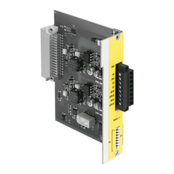
- Page 12 Italian/Chinese Tab. 9: Scope of delivery Function and application The safety module CAMC-G-S1 has the following performance characteristics: – Reaching the "Safe Torque Off" (STO) function, – Potential-free feedback contact for the operating status, – Design as a module that can be plugged in from the outside thus enabling retrofits, –...
- Page 13 Product description of safety module CAMC-G-S1 Fig. 2: “Safe torque off ” - functional principle for the CMMP-AS-…-M3 Safety circuit (switch, relay, safety relay Motor connection unit) LED (green/yellow), status indicator Safety module CAMC-G-S1 Feedback contact Power output stage in the CMMP-AS-…-M3...
- Page 14 Product description of safety module CAMC-G-S1 3.2.2 Overview of interface [X40] The safety module has an 8-pin connection [X40] on the front for control inputs, feedback contact and a 24 V auxiliary supply for external sensors è 4.2 Electrical installation.
- Page 15 The transition between a safe and an unsafe state is initiated by level changes at the STO-A and STO-B control inputs of the safety module CAMC-G-S1. According to the specification of the safety function, both levels must be identical, otherwise an error message is generated. The state machine in the motor controller internally monitors the driver supply voltages as a result of the control of the control inputs.
- Page 16 24 V, 0 V auxiliary power supply [X40] The motor controller CMMP-AS...-M3 with the safety module CAMC-G-S1 provides a 24 V auxiliary supply at [X40]. This can be employed when using the C1/C2 feedback contact or for power to external active sensors.
- Page 17 Product description of safety module CAMC-G-S1 The safety module CAMC-G-S1 exclusively controls the provision of the driver power supply for the motor controller CMMP-AS-...-M3. Although the levels of the input voltage are monitored section by section, the safety module does not have its own error evaluation mechanisms and also does not have the option of displaying an error.
- Page 18 Product description of safety module CAMC-G-S1 Function Reaction time Reaction Switching time from T_STO-A/B_OFF è 8.1.4 Electrical data, è Tab. 31 Technical high to low data: electrical data of the STO-A and STO-B inputs Switching time from T_STO-A/B_ON low to high £...
- Page 19 Product description of safety module CAMC-G-S1 Fig. 3: Basic time response when activating and deactivating the STO safety function Time Description Value T_STO-A/B_OFF STO-A/B – switching time from high to low è 8.1.4 Electrical data, è Tab. 31 Technical data: T_STO-A/B_ON STO-A/B –...
- Page 20 Product description of safety module CAMC-G-S1 Fig. 4: Time response when activating the STO safety function with restart Time Description Value T_STO-A/B_OFF STO-A/B – switching time from high to low è 8.1.4 Electrical data, è Tab. 31 Technical data: T_STO-A/B_ON STO-A/B –...
- Page 21 Product description of safety module CAMC-G-S1 3.4.3 Time response of activation of SS1 in operation with restart The time response in the following figure is based on the example circuit for SS1 in è 4.3.2 Decelera- tion and Safe Torque Off (SS1, "Safe Stop 1"), based on the control signal S1 for K1. The times can be found in the table below.
- Page 22 Product description of safety module CAMC-G-S1 Time Description Value >20 ms T_DIN5_SU Time that DIN5 must still be low after switching on STO-A/B again and changing the status of the STO module T_BRAKE_V_ON Switch-off delay of the holding brake Depending on the brake...
- Page 23 Assembly and installation Mounting/removal The safety module CAMC-G-S1 is suitable exclusively for integration into the motor controller CMMP- AS-…-M3. It cannot be operated outside the motor controller. The motor controller must be disconnected from any live cables before installing and removing the safety module.
- Page 24 (e. g. shoes, earthing straps etc.). 4.2.2 Connection [X40] The safety module CAMC-G-S1 has a combined interface for control and feedback via the plug con- nector [X40]. – Version on the device: PHOENIX MINICOMBICON MC 1.5/8-GF-3.81 BK – Plug (in scope of delivery): PHOENIX MINICOMBICON MC 1.5/8-STF-3.81 BK, connection corre- sponding to è...
- Page 25 If a switch module is not available or the motor controller is to be initially commissioned without safety engineering, the motor controller CMMP-AS-…-M3 can be wired to the safety module CAMC-G-S1 with minimum circuitry with an emergency stop switch è Fig. 7, [2]. NOTICE Safety functions must never be bypassed.
- Page 26 The direct wiring of light curtains means that detection of shorts across contacts is implemented by the light curtain, if it is designed for this purpose. – When using safety relay units, contact C1, C2 can be integrated into the feedback circuit of the safety relay unit. Festo — CAMC-G-S1 — 2022-07d...
- Page 27 After a time set in the safety relay unit, the output stage is switched off via 2 channels via STO-A/B. If the power stage has been switched off, it is output by the potential-free contact C1-C2. Festo — CAMC-G-S1 — 2022-07d...
- Page 28 The time delay must be designed in such a way that the drive is braked to zero even at the highest speed via the quick stop ramp in CMMP-AS...-M3 before STO-A/B are switched off. Festo — CAMC-G-S1 — 2022-07d...
- Page 29 – The sample circuit has a 2-channel structure that is suitable for categories 3 and 4 with additional measures. – The additional measures required depends on the area of application and the safety concept of the machine. Festo — CAMC-G-S1 — 2022-07d...
- Page 30 For the safety module project engineering, insert the safety module into the FCT on the ‘Configuration’ screen of the CMMP-AS plug-in with ‘Create new drive configuration’ or ‘Change drive configuration’, see the following figure. Festo — CAMC-G-S1 — 2022-07d...
- Page 31 The following rules apply to the module replacement: • It is always possible to replace a switch module with another switch module. • It is not necessary to confirm the replacement of a CAMC-G-S1 module with another CAMC-G-S1 module. Exception: the version check in the basic unit shows that the modules are incompatible - error message 51-3 - meaning that the module change must be confirmed.
- Page 32 The ‘Confirm module change’ dialogue displays the module type, overall revision (CAMC-G-S3) or revision and version (CAMC-G-S1, CAMC-DS-M1) and the serial numbers of the previous module and also of the currently installed module. – Selecting ‘Yes’ confirms the module replacement, the parameters are permanently saved in the basic unit and the system is restarted.
- Page 33 Time stamp Time of the diagnostic event in <hh>:<mm>:<ss> format (operating hour counter, duty cycle of the logic supply). Constant Additional information for Festo service personnel Free parameter Additional information for Festo service personnel Type Type of entry (error, warning, log entry).
- Page 34 Can it be guaranteed that the implemented protective meas- Yes 0 No 0 ures have not led to a deterioration in the working condi- tions of the operating personnel? Are the implemented protective measures mutually compat- Yes 0 No 0 ible? Festo — CAMC-G-S1 — 2022-07d...
- Page 35 The following must be inspected as a minimum as part of the validation: Check the components: is the CMMP-AS-…-M3 being Yes 0 No 0 used with the CAMC-G-S1 (check the rating plates). Is the wiring correct (check the circuit diagram)? Yes 0 No 0 Have any jumpers been removed?
- Page 36 Tab. 20: Questions for validation in accordance with EN ISO 13849-1 and -2 (example) Festo — CAMC-G-S1 — 2022-07d...
- Page 37 Yellow Safe = STO status active The power output stage in the motor con- troller for the power supply to the motor is safely switched off. Tab. 21: LED indicator on the safety module Festo — CAMC-G-S1 — 2022-07d...
- Page 38 – Load firmware appropriate for the safety or switch module, see order reference on the module. 51-2 8093h Safety module: different module type PSoff Cause Type or revision of the module does not match the project engi- neering. Festo — CAMC-G-S1 — 2022-07d...
- Page 39 Safety function: discrepancy time exceeded PSoff – Control inputs STO-A and STO-B are not actuated simultane- Cause ously. – Check discrepancy time. Action – Control inputs STO-A and STO-B are not wired in the same Cause direction. Festo — CAMC-G-S1 — 2022-07d...
- Page 40 It can occur when customer-specific device firmware is used. – The safe status was requested with power output stage ena- Action bled. Check integration into the safety-oriented interface. Tab. 24: Error group 52 Festo — CAMC-G-S1 — 2022-07d...
- Page 41 CMMP-AS-…-M3 The devices of the CMMP-AS-M3 series, in combination with the CAMC-G-S1, have the safety function STO "Safe Torque Off" in accordance with EN 61800-5-2 SIL3, or EN ISO 13849-1, Cat 4/PL e. The two switch-off paths are implemented via the control inputs STO-A [X40.1] and STO-B [X40.3].
- Page 42 If these values increase and the risk increases as a result, a new risk assessment of the machine must be carried out. NOTICE After replacing the motor controller, the safety function must be validated in accordance with the machine manufacturer's specifications. Festo — CAMC-G-S1 — 2022-07d...
- Page 43 The functional safety engineering of the product has been cer- tified by an independent body, see UK-type examination certifi- cate è www.festo.com/sp Certificate issuing authority TUV Rheinland UK Ltd, Approved Body for Machinery, No. 2571 Certificate no. 01/205U/5165.02/19 Tab. 25: Approval information, safety engineering Festo — CAMC-G-S1 — 2022-07d...
- Page 44 Tab. 26: Safety engineering 8.1.2 General General Certificates, declaration of conformity è www.festo.com/sp The device is intended for use in an industrial environment. Measures for interference suppression may be required in residential areas. Dimensions (L x W x H) [mm] Approx.
- Page 45 Overvoltage shutdown 31 (shutdown in case of fault) Nominal current [mA] 20 (typical; maximum 30) Starting current [mA] 450 (typical, duration approx. 2 ms; max. 600 at 28.8 V) Input voltage threshold Switching on approx. 18 Festo — CAMC-G-S1 — 2022-07d...
- Page 46 Service life (switching cycles) 10 x 10 (at 24 V and I = 10 mA; the service life is contact reduced at higher load currents) Tab. 33: Technical data: electrical data of the feedback contact C1/C2 Festo — CAMC-G-S1 — 2022-07d...
- Page 47 Conductor cross section (flexible conductors, wire end sleeve with insulating collar) one conductor 0.25 … 0.5 two conductors 2 x 0.25 (with twin wire end sleeves) Tightening torque M2 [Nm] 0.22 … 0.25 Tab. 36: Technical data: wiring at [X40] Festo — CAMC-G-S1 — 2022-07d...
- Page 48 DC avg Average Diagnostic Coverage, diagnostic coverage in accordance with IEC 61508 and EN 61800-5-2. Festo Configuration Tool, software for configuration and commissioning. Hardware Fault Tolerance in accordance with IEC 61508. Cat. Category in accordance with EN ISO 13849-1, steps 1-4.
- Page 50 Copyright: Festo SE & Co. KG 73734 Esslingen Ruiter Straße 82 Deutschland Phone: +49 711 347-0 Internet: © 2022 all rights reserved to Festo SE & Co. KG www.festo.com...
Need help?
Do you have a question about the CAMC-G-S1 and is the answer not in the manual?
Questions and answers