Sign In
Upload
Manuals
Brands
Festo Manuals
Control Unit
CAMC-G-S3
Festo CAMC-G-S3 Manuals
Manuals and User Guides for Festo CAMC-G-S3. We have
4
Festo CAMC-G-S3 manuals available for free PDF download: Manual, Translation Of The Original Instructions, Instructions | Safety Function, Advanced Safety
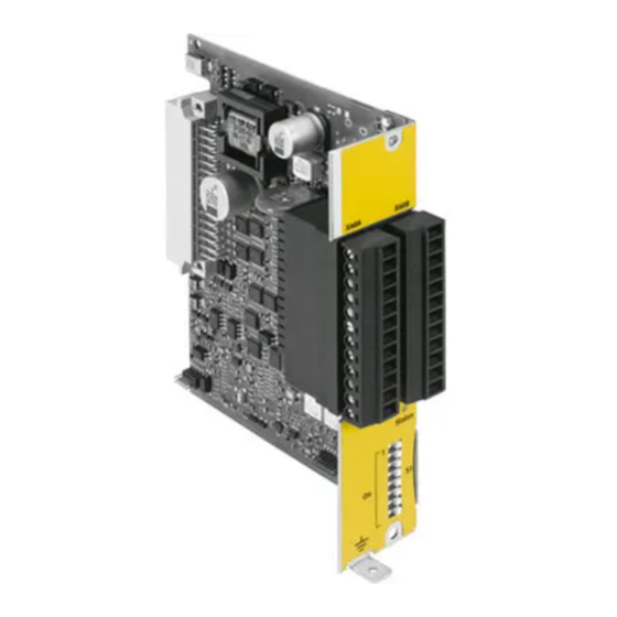
Festo CAMC-G-S3 Manual (310 pages)
Safety module
Brand:
Festo
| Category:
Control Unit
| Size: 2 MB
Table of Contents
- Camc-G-S
3
Table of Contents
3
Table of Contents - CAMC-G-S3
11
1 Safety and Requirements for Product Use
13
Safety
13
General Safety Information
13
Intended Use
13
Foreseeable Misuse
14
Achievable Safety Level
15
Safety Function in Accordance with en ISO 13849-1 / en 61800-5-2
15
Requirements for Product Use
16
Technical Prerequisites
16
Qualification of the Specialised Personnel (Personnel Requirements)
16
Diagnostic Coverage (DC)
16
Range of Application and Certifications
17
2 Product Description of Safety Module CAMC-G-S3
18
Product Overview
18
Purpose
18
Performance Characteristics
18
Supported Devices
19
Operating Elements and Connections
20
Scope of Delivery
20
Function and Application
21
System Overview
21
Circuitry of the Safety Module [X40]
23
Overview of the Supported Safety Functions
25
Functional Diagram of the Safety Module
26
Overview of Supported Position Encoders
30
Data Exchange and Control of the Motor Controller
33
Configuration of the Safety Functions with the Safetytool
36
Data Transfer from the Motor Controller
37
Basic Information
38
Configuration of the Encoders
40
Parameters for the Position Encoder
41
Parameter for Encoder Monitoring and Rotational Speed Measuring
43
List of All Parameters for Encoder Configuration
46
Digital Inputs
48
Overview
48
Two-Channel Safe Inputs DIN40
53
Single-Channel (Partially-Safe) Digital Inputs DIN44
59
Safety Functions
63
STO – Safe Torque off
66
SBC – Safe Brake Control
69
SS1 – Safe Stop 1
77
SS2 – Safe Stop 2
84
SOS – Safe Operating Stop
91
USF – Universal Safety Functions
95
SLS – Safely-Limited Speed
103
SSR – Safe Speed Range
104
SSM – Safe Speed Monitor
105
Logic Functions
106
Two-Handed Control Device
108
Advanced Logic Functions – ALF
110
Restart
111
Examples and Special Notes on Implementation
112
Error Management and Error Acknowledgment
114
Parameterisation of the Error Response of the Safety Module
117
Logic for Error Acknowledgment
118
Digital Outputs
120
Internal Brake Control of the Motor Controller [X6]
124
Signal Contact C1, C2 [X40]
127
Auxiliary Supply +24 V [X40]
129
Operating Status and Status Displays
130
Status Display on the Safety Module
134
Segment Display of the Motor Controller
135
Runtime Performance
137
Reaction Time on Violation of a Safety Function
139
Other Times for Error Detection and Communication
141
3 Mounting and Installation
142
Electrical Installation
144
Functional Earth
145
Minimum Wiring for Commissioning [X40]
147
Sample Circuits
148
Safety Request Via Devices with Switch Contacts
149
Safety Request Via Devices with Semi-Conductor Outputs
150
Safety Request Via a Safety Switching Device
151
Linking of Multiple CMMP-AS-...-M3 with CAMC-G-S3
153
Activating a Clamping Unit
155
Activating a 2-Channel Clamping Unit
156
Connection of Encoders for Dynamic Safety Functions
157
Activation of a 2-Channel Valve Control Block with Safety Functions
158
4 Commissioning
161
Prior to Commissioning
162
Notes on Parameterisation with the FCT Plug-In CMMP-AS
163
Specifying the Units of Measurement (Optional)
164
Status Display
165
Basic Principles of Parameterisation of the Safety Module
168
Delivery Status
170
Safe Parameterisation with the Safetytool
171
Online Parameterisation
172
Offline Parameterisation
174
Basic Rules for Parameterisation with the Safetytool
175
Behaviour in Case of Invalid Parameterisation
178
Sequence of Parameterisation with the Safetytool (Example)
179
Selection of the Session Variant in the Wizard
180
Data Transfer and Synchronisation
181
Starting Parameterisation
183
Checking the Data Transfer
184
Configuring Digital Inputs
185
Selection and Parameterisation of the Safety Functions
186
Logic Functions
190
Logic Error Acknowledgment
191
Special Functions of the Safetytool
193
Overview of Parameters
194
Diagnostic Fault
195
Performance Test, Validation
197
5 Operation
200
Fail-Safe Mode Power Supply
201
Protective Functions of the Supply for Driver Activation
202
Monitoring Compliance with the Requested Safety Functions
203
Diagnostics and Fault Clearance
204
Segment Display of the Motor Controller
205
Error Messages and Error Handling
207
Diagnostic Messages
208
Diagnostic Messages with Instructions for Fault Clearance
209
6 Service, Repair, Replacement, Waste Management
226
Disassembly and Installation
227
De-Commissioning and Disposal
228
A Technical Appendix
229
A.1.2 General
230
A.1.3 Operating and Ambient Conditions
231
A.1.4 Digital Inputs DIN40A/B to DIN43A/B and DIN44 to DIN49 [X40]
233
A.1.5 Digital Outputs DOUT40A/B to DOUT42A/B [X40]
234
A.1.6 Signal Contact C1/C2 [X40]
235
A.1.8 Version of the Connecting Cable [X40]
236
A.2 Safety Data
238
A.2.2 Digital Inputs
239
A.2.3 Encoder Systems
241
A.2.4 Digital Outputs
258
A.3 System Precision and Reaction Time
260
A.3.1 Accuracy of Position Monitoring (SOS) from the Point of View of the Application
261
A.3.2 Accuracy of Speed Monitoring (SLS, SSR from the Point of View of the Application
262
A.3.3 Specification of the Relevant Parameters for Safe Speed Function (with SLS, SSR
263
A.3.4 Requirements for Encoder Errors from the Point of View of the Application
264
A.3.5 Vector Length Monitoring of Analogue Encoder Signals (Resolver, SIN/COS Encoder
267
A.3.6 Impact of an Angle Error Within the Error Limits of Vector Length Monitoring on the Speed Signal
270
A.3.7 Basis for Observation of System Accuracy
272
A.4 Status Messages, Diagnostics Via Fieldbus
274
A.4.2 Status Signals Via Fieldbus – Protocol Cia 402
275
Output Stage
279
Vout_Error
279
Vout_Ps_En
279
Vout_Scv
279
Vout_Ssr
279
A.4.3 Status Signals Via Fieldbus – Protocol FHPP
279
A.5 Recording Trace Data - "Trace
282
A.5.3 Start Trace
284
B Reference List for Control Signals and Parameters
286
B.1.2 Virtual Inputs VIN
289
B.1.3 Virtual Outputs VOUT
290
Vout_Warn
279
At Least One Error with the Priority "Warning" Has Occurred
291
At Least One Safety Condition was Violated
291
Function
291
Service" Status, no Parameters Present, para
291
Status Bit Specifies Whether the Motor Control
291
The Safety Module Has Detected an Internal Error
291
B.1.4 Logical Outputs LOUT
292
B.1.5 Status Words for the Data Exchange / Diagnostics Via Fieldbuses
293
B.2 List of Additional Parameters
295
B.3 List of Important Communication Objects in the Basic Unit
302
C Glossary
305
C.2 Terms for the Safetytool and for Safe Parameterisation
307
Vout_Ready
291
Vout_Service
291
Vout_Sfr
291
Advertisement
FESTO CAMC-G-S3 Translation Of The Original Instructions (24 pages)
Safety module for the motor controller
Brand:
FESTO
| Category:
Control Unit
| Size: 1 MB
Table of Contents
Table of Contents
4
Sicherheitsmodul bei Bedarf auf Werkseinstellung Setzen
4
En Iso 13849-1
5
600 DC [%] 97,5 Diagnosedeckungsgrad nach en 61800-5-2, en 61508 und
16
EN 62061 und en 61508
16
MTTF [Jahre] 8700 Mittlere Zeit bis zum Gefahrbringendenausfallnach
16
1 ) Maximalerreichbare Einstufung, Einschränkungenabhängig von der Sicherheitsfunktionsowie der
16
Pfh -1
16
Hft
16
Sff [%]
16
T [Jahre]
16
T M [Jahre]
16
EN ISO 13849-1 und en 62061
16
Cmmp-As
16
C5-3A-M3
16
[V DC] 24
16
[V DC] 18
16
C5-11A-P3-M3 C10-11A-P3-M3
24
Festo CAMC-G-S3 Translation Of The Original Instructions (4 pages)
Safety module
Brand:
Festo
| Category:
Control Unit
| Size: 0 MB
Table of Contents
Applicable Documents
1
Safety
1
General Safety Instructions
1
Intended Use
1
Foreseeable Misuse
1
Achievable Safety Level, Safety Function in Accordance with en ISO 13849/EN 61800-5-2
1
Requirements for Product Use
1
Technical Prerequisites
1
Qualification of the Specialist Technicians (Requirements for Staff)
1
Diagnostic Coverage (DC)
1
Operating Elements and Connections
2
Function and Application
2
Mounting/Removal
2
Electrical Installation
2
Safety Instructions
2
Connection [X40]
2
Commissioning
2
Prior to Commissioning
2
DIL Switch Setting
2
Parameterisation with the Parameterisation Software for the CMMP-AS
3
Accepting the Safety Module
3
Parameterisation of the Safety Module with the Safetytool
3
Function Test, Validation
3
Diagnostics and Fault Clearance
3
Status Display
3
Malfunction Messages
3
Operation and Use
3
Maintenance and Care
3
Repair, Replacement of the Safety Module
3
Product Description
4
Decommissioning and Disposal
4
Technical Data
4
Approval Information, Safety Engineering
4
Safety Engineering
4
General
4
Operating and Environmental Conditions
4
Electrical Data
4
Advertisement
Festo CAMC-G-S3 Instructions | Safety Function, Advanced Safety (4 pages)
Safety module
Brand:
Festo
| Category:
Control Unit
| Size: 1 MB
Table of Contents
Applicable Documents
1
Safety
1
General Safety Instructions
1
Intended Use
1
Foreseeable Misuse
1
Achievable Safety Level, Safety Function in Accordance with en ISO 13849/EN 61800-5-2
1
Requirements for Product Use
1
Technical Prerequisites
1
Qualification of the Specialist Technicians (Requirements for Staff)
1
Diagnostic Coverage (DC)
1
Operating Elements and Connections
2
Function and Application
2
Mounting/Removal
2
Electrical Installation
2
Safety Instructions
2
ESD Protection
2
Connection [X40]
2
Commissioning
2
Prior to Commissioning
2
DIP Switch Setting
2
Diagnostics and Fault Clearance
3
Status Display
3
Parameterisation of the Safety Module with the Safetytool
3
Function Test, Validation
3
Malfunction Messages
3
Operation and Use
3
Obligations of the Operator
3
Maintenance and Care
3
Repair, Replacement of the Safety Module
3
Repair
3
Disposal
4
Technical Data
4
Advertisement
Related Products
Festo CAMC-G-S1
Festo CPX-FB6
Festo Smart cubic CPVSC1-VI
Festo CPX-M-4-M12x2-5POL
Festo CPV-D102
Festo CPV-DI02
Festo CDVI5.0
Festo CPV10-GE-DI02-8
Festo CPX-E Series
Festo CAMC-D-8E8A
Festo Categories
Industrial Equipment
Control Unit
Controller
Touch terminals
DC Drives
More Festo Manuals
Login
Sign In
OR
Sign in with Facebook
Sign in with Google
Upload manual
Upload from disk
Upload from URL