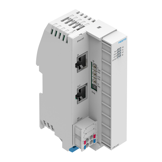
Festo CPX-E-PN Manual
System cpx-e, bus module
Hide thumbs
Also See for CPX-E-PN:
- Instructions for use (3 pages) ,
- Translation of the original instructions (20 pages) ,
- Instructions (4 pages)
Summary of Contents for Festo CPX-E-PN
- Page 1 System CPX-E Bus module CPX-E-PN Description Protocol PROFINET Function Parameterisation 8071139 2017-07 [8071141]...
- Page 2 CPX-E-PN-E N ® ® PI PROFIBUS PROFINET , PROFIenergy are registered trademarks of the respective trademark owners in certain countries. Symbols used: Note Material damage or loss of function Recommendations, tips, references to other documentation Festo – CPX-E-PN-EN – 2017-07 –...
-
Page 3: Table Of Contents
..................Festo – CPX-E-PN-EN – 2017-07 – English... -
Page 4: About This Document
Bus module CPX-E-PN as of Revision 1 Tab. 1.2 The product version can be identified from the product label or with the help of appropriate software from Festo. Appropriate software for identifying the product version can be found in the Festo Support Portal è... -
Page 5: Product Labelling
The product labelling is located on the left-hand side of the module. Scanning the printed Data Matrix Code with an appropriate device calls up the Festo Support Portal, with information appropriate for the product. Alternatively, the Product Key (11-digit alphanumeric code on the product labelling) can be entered in the search field of the Support Portal. -
Page 6: Function
A device description file (GSDML file) is used for configuring the bus module in the higher-order controller software. This file contains all the information required for parameterising the system CPX-E using controller software (such as Siemens STEP 7). The device description file is available on the Festo Support Portal (è www.festo.com/sp). 2.1.3 PROFIenergy The product supports the PROFIenergy profile for energy management. -
Page 7: Product Design
+24 V DC operating voltage supply U EL/SEN 0 V DC operating voltage supply U EL/SEN 1) The ports XD.0 and XD.1 and also XD.2 and XD.3 are interconnected in the terminal strip. Tab. 2.2 Festo – CPX-E-PN-EN – 2017-07 – English... -
Page 8: Address Assignment
The inputs and outputs of different module types are assigned separately from each other. Addressing is generally carried out by the higher-order controller (in cases where a Siemens higher-order controller is being used). 2.3.2 Addressing example 1 Bus module CPX-E-PN (with status bits) Module no.: – Status bits activated –... -
Page 9: Diagnostics Options
è 2.5 PROFINET IO Diagnostics as part of PROFINET IO functions via the network. Detailed module-related and channel-related error detection by means of control software. Tab. 2.4 Festo – CPX-E-PN-EN – 2017-07 – English... -
Page 10: Led Indicators
Network connection OK – Lights up Module positioning if both LEDs (XF1 and XF2) – flash synchronously, e.g. for troubleshooting Flashes purposes or during configuration No network connection • Check network connection. Tab. 2.7 Festo – CPX-E-PN-EN – 2017-07 – English... -
Page 11: Status Bits
The I/O diagnostic interface is shown in the process image if this has been specified by selecting the catalogue entry “E-PN [STI]” in the hardware configurator. You can find detailed information about the I/O diagnostic interface in the “Description of system CPX-E” è 1.1 Further applicable documents. Festo – CPX-E-PN-EN – 2017-07 – English... -
Page 12: Diagnostics Via Profinet Io
Parameterisation error (error in “safe parameterisation”) Over-temperature Electronics and sensors undervoltage Tab. 2.8 You can find a list of all CPX-E-specific error numbers in the “Description of system CPX-E” è 1.1 Further applicable documents. Festo – CPX-E-PN-EN – 2017-07 – English... -
Page 13: Parameterisation
Parameterisation Parameterisation The behaviour of the system CPX-E can be parameterised with the aid of suitable software from Festo or using a higher-order controller. Here, a distinction is made between the following variants: – System parameters – Module parameters (module-specific and channel-specific) –... -
Page 14: A Technical Data
Wire cross section [mm²] 0.14 … 0.75; 22 AWG 1) Based on the Ethernet protocol IEEE 802.3 2) Standards with reference to PROFINET 3) Required for maximum connection length between network participants Tab. A.3 Festo – CPX-E-PN-EN – 2017-07 – English... -
Page 15: B Terminology
Collective term for modules that can be integrated in a system CPX-E. Programmable logic controller Status bits Internal status information (common diagnostic messages) of the system CPX-E, provided as input signals via the network. System CPX-E Complete system consisting of modules CPX-E. Tab. B.1 Festo – CPX-E-PN-EN – 2017-07 – English... -
Page 16: Index
Technical data, 14 Terminology, 15 I/O diagnostic interface, 11 Identification & Maintenance, 6 UOUT monitoring, 13 LED indicators, 10 – Connection status, 10 Web server, 6 – Maintenance/PROFIenergy, 10 – Network errors, 10 Festo – CPX-E-PN-EN – 2017-07 – English... - Page 18 Copyright: Festo AG & Co. KG Ruiter Straße 82 73734 Esslingen Germany Phone: +49 711 347-0 Fax: +49 711 347-2144 e-mail: Reproduction, distribution or sale of this document or communication of service_international@festo.com its contents to others without express authorization is prohibited. Offend...


Need help?
Do you have a question about the CPX-E-PN and is the answer not in the manual?
Questions and answers