Festo CPX-FB40 Description
Terminal cpx, bus node, network protocol ethernet powerlink
Hide thumbs
Also See for CPX-FB40:

Related Manuals for Festo CPX-FB40


Summary of Contents for Festo CPX-FB40
- Page 1 Terminal CPX Bus node CPX-FB40 Description Electronics Network protocol Ethernet POWERLINK 8028651 1408NH [8028657]...
- Page 2 Essential or useful accessories. Information on environmentally sound usage. Text designations: • Activities that may be carried out in any order. 1. Activities that should be carried out in the order stated. – General lists. Festo – P.BE-CPX-FB40-EN – 1408NH –...
-
Page 3: Table Of Contents
Bus node CPX-FB40 Table of Contents – Bus node CPX-FB40 Safety and requirements for product use ........ - Page 4 ........3.7.3 Parameterisation via the Festo Maintenance Tool (CPX-FMT) software ..
- Page 5 ....Festo profile for CPX terminals (dynamic equipment configuration) ....
- Page 6 Information about additional CPX modules can be found in the description for the respective module. All documents can also be found in the Internet ( www.festo.com). Service Please consult your regional Festo contact if you have any technical problems. Festo – P.BE-CPX-FB40-EN – 1408NH – English...
-
Page 7: Safety And Requirements For Product Use
The module is intended exclusively for use in CPX terminals from Festo for installation in machines or automated systems and may be used only in the following ways: –... -
Page 8: Requirements For Product Use
(e.g. CPX system description P.BE-CPX-SYS-…). • Take into consideration the legal regulations applicable for the destination, as well as: – regulations and standards – regulations of the testing organizations and insurers – national specifications. Festo – P.BE-CPX-FB40-EN – 1408NH – English... -
Page 9: Technical Prerequisites
Standards and test values, which the product complies with and fulfils, can be found in the “Technical data” section ( Appendix A.1). The product-relevant EU directives can be found in the declaration of conformity. Certificates and declaration of conformity on this product can be found at www.festo.com. Festo – P.BE-CPX-FB40-EN – 1408NH – English... -
Page 10: Installation
Ensuring degree of protection IP65/IP67 • Use connection technology with degree of protection IP65/IP67 www.festo.com/catalogue, examples in Tab. 2.1). • Use cover caps to seal unused connections 2.3.3 Complying with degree of protection IP65/IP67). Festo – P.BE-CPX-FB40-EN – 1408NH – English... -
Page 11: Electrical Connections And Indicators
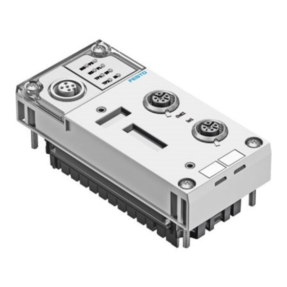
(CPX-MMI) or the adapter for the Festo Maintenance Tool (CPX-FMT) 1) M12 socket, D-coded, 4-pin 2) M12 socket, A-coded, 5-pin 3) Adapter NEFC-M12G5-0.3-U1G5 for parameterisation via a USB connection Fig. 2.1 Festo – P.BE-CPX-FB40-EN – 1408NH – English... -
Page 12: Mounting And Dismantling
4. Tighten the screws in diagonally opposite se- quence. Tightening torque: 0.9 … 1.1 Nm. Screws Module Interlinking block Fig. 2.2 2.3.2 Dismantling 1. Unscrew screws. 2. Pull the module without tilting out of the interlinking block. Festo – P.BE-CPX-FB40-EN – 1408NH – English... -
Page 13: Complying With Degree Of Protection Ip65/Ip67
• Use cover caps to seal unused connections. Port Connection technology Cover cap Network connection Plug NECU-M-S-D12G4-C2-ET ISK-M12 Service interface Connecting cable KV-M12-M12-… 1) Connecting cable for operator unit (CPX-MMI) 2) Included in the scope of delivery Tab. 2.1 Festo – P.BE-CPX-FB40-EN – 1408NH – English... -
Page 14: Settings Of The Dil Switches On The Bus Node
– diagnostics mode (Remote I/O) – I/O mode (Remote controller) DIL switch 3: – station number (1 … 239) 1) The function is dependent on the set operating mode ( DIL switch 1) Fig. 2.3 Festo – P.BE-CPX-FB40-EN – 1408NH – English... -
Page 15: Setting The Dil Switches
EHTERNET POWERLINK network. Tab. 2.2 Note Setting of the operating mode via DIL switch 1 has priority over all other settings. The switch element 1.2 of DIL switch 1 is reserved and without function. Festo – P.BE-CPX-FB40-EN – 1408NH – English... -
Page 16: Setting Of The Diagnostic Mode (Remote I/O)
Subsequent activation of the diagnostics mode requires a reconfiguration. • Observe that the CPX-internal I/O image can be displaced during subsequent activa- tion of the diagnostics mode. • In this case, repeat the Ethernet POWERLINK network configuration. Festo – P.BE-CPX-FB40-EN – 1408NH – English... -
Page 17: Setting Of The I/O Mode (Remote Controller)
Station 38 Station 55 Station 106 Station 239 – – – – – – – – – – – – – – – – – – – Address: Address: Address: Address: Address: Tab. 2.6 Festo – P.BE-CPX-FB40-EN – 1408NH – English... -
Page 18: Connecting To The Network
– faulty screened connection – branches – transmission over distances which are too long – unsuitable cables. Connection technology Network connectors 2 x M12-socket, D-coded, 4-pin, Plug NECU-M-S-D12G4-C2-ET corresponding to IEC 61076-2, SPEEDCON compatible Tab. 2.7 Festo – P.BE-CPX-FB40-EN – 1408NH – English... -
Page 19: Cable Specification
The screened connection of the two network connections is connected to the earth potential of the CPX terminal through an RC element. • Connect the earth connection on the left end plate of the CPX-terminal with the earth potential over a large surface. Festo – P.BE-CPX-FB40-EN – 1408NH – English... -
Page 20: Setting The Ip Address
Tab. 2.10 Subnet mask The subnet mask is always 255.255.255.0. Gateway address The gateway address is set at the factory to 192.168.100.240 and can be changed via CPX parameters or AS startup parameters. Festo – P.BE-CPX-FB40-EN – 1408NH – English... -
Page 21: Webserver Function
Installation 2.5.6 Webserver function A web server is integrated in the bus node CPX-FB40. It makes available read access to the most im- portant parameters and diagnostic functions of the CPX terminal. Procedure 1. Open an Internet browser of your choice on a PC that is connected to the network. -
Page 22: Commissioning
CPX terminal. The number of occupied inputs and outputs of the respective module can be found in the following tables: – bus node ( Tab. 3.1) – analogue modules ( Tab. 3.2) – technology modules ( Tab. 3.3) – digital modules ( Tab. 3.4). Festo – P.BE-CPX-FB40-EN – 1408NH – English... -
Page 23: Bus Node Cpx-Fb40
1) Module identifier in the operator unit or in the hardware configuration of the programming software 2) Depending on the configuration. Tab. 3.2 The address assignment within the individual CPX analogue I/O modules can be found in the description for the analogue I/O modules ( P.BE-CPX-AX-…). Festo – P.BE-CPX-FB40-EN – 1408NH – English... -
Page 24: Technology Modules
1) Module identifier in the operator unit or in the hardware configuration of the programming software 2) Maximum assigned address space is dependent on the string allocation Tab. 3.3 Details on the technology modules can be found in the corresponding descriptions P.BE-CPX-…). Festo – P.BE-CPX-FB40-EN – 1408NH – English... -
Page 25: Digital Modules
3) Electronic/electrical modules VMPA1 always occupy 8 outputs independent of the number of attached valves. 4) Electronic/electrical modules VMPA2 always occupy 8 outputs, although only 4 bits are used. 5) Setting via DIL switches of the pneumatic interface. Festo – P.BE-CPX-FB40-EN – 1408NH – English... - Page 26 – An overview of the “Descriptions of the CPX terminal” documentation can be found in the CPX system description ( P.BE-CPX-SYS-…). – From the technical point of view, the individual pneumatic modules each represent an electric module for controlling the attached valves. Festo – P.BE-CPX-FB40-EN – 1408NH – English...
-
Page 27: Determination Of The Address Assignment
2) Digital modules with 4 inputs or outputs (CPX-4DE, CPX-4DA) as well as electric modules and electronic modules VMPA2 always occupy 8 inputs or 8 outputs. 3) At the factory, 32 O (VABA, VMPAL) are configured. Tab. 3.5 Festo – P.BE-CPX-FB40-EN – 1408NH – English... -
Page 28: Addressing
– electrical interface CPX-CP-4-FB 4. Digital modules Modules with digital inputs/outputs 1) Status bits and I/O diagnostics interface can be activated via DIL switch 2 ( 2.4.5 Setting of the diagnostic mode (Remote I/O)). Tab. 3.6 Festo – P.BE-CPX-FB40-EN – 1408NH – English... -
Page 29: Example 1: Cpx Terminal With Electronic Modules Vmpa1 And Vmpa2
VMPA1 (8DO) – O8 … O15 VMPA1 (8DO) – O16 … O23 VMPA2 (4DO) – O24 … O31 VMPA2 (4DO) – O32 … O39 1) 8 bits occupied, 4 bits used Tab. 3.7 Festo – P.BE-CPX-FB40-EN – 1408NH – English... -
Page 30: Example 2: Cpx Terminal With Electrical Interface (Cp Interface)
I0 … I31 O0 … O127 CPX-8DE-8DA I40 … I47 O136 … O143 VMPA1 (8DO) – O144 … O151 VMPA1 (8DO) – O152 … O159 1) 8 bits occupied, 4 bits used Tab. 3.8 Festo – P.BE-CPX-FB40-EN – 1408NH – English... -
Page 31: Example 3: Cpx Terminal With Analogue Module And Pneumatic Interface
O0 … O31 VABA-… (1 … 8 solenoid coils) – O48 … O55 1) 16 bits occupied, 8 bits used 2) 8 bits occupied, 4 bits used 3) Set via·DIL switches. Tab. 3.9 Festo – P.BE-CPX-FB40-EN – 1408NH – English... -
Page 32: Address Assignment After Extension/Conversion
Moreover, it should be noted that the needed address space may increase due to modific- ation of the CPX terminal and thus the slave addresses of the following slaves in the net- work must be checked and adjusted if necessary. Festo – P.BE-CPX-FB40-EN – 1408NH – English... -
Page 33: Ethernet Powerlink
Besides the generic device profile, the bus node also supports a dynamic (manufacturer-specific) profile. As a result, I/O configuration can be executed by slot through the export function of the Festo Maintenance Tool (CPX-FMT) software. -
Page 34: Device Description
3.5.1 Dynamic device description (XDC file) With the help of the Festo Maintenance Tool (CPX-FMT) software, the device description file of a CPX terminal can be dynamically generated in the form of an XDC file (XML Device Configuration). The Festo Maintenance Tool (CPX-FMT) software is available for download in the Festo Support Portal ( www.festo.com/sp). -
Page 35: Exporting Xdc File With The Cpx-Fmt
3.5.2 Exporting XDC file with the CPX-FMT With the export function of the Festo Maintenance Tool (CPX-FMT) software, you can export a dynamic device description file (XDC file) of your CPX terminal and then import it into the Automation Studio software. -
Page 36: Generic Device Description (Xdd File)
The device description can be made generically with help of a device-specific XDD file (XML Device Description). The generic device description uses the device profile in accordance with DS 401 and is able to depict all CPX configurations. The corresponding file “0000001D_CPX_FB40.xdd” is available for download in the Festo Support Portal ( www.festo.com/sp). -
Page 37: Automation Studio" Controller Software
Configuration of a CPX terminal in an Ethernet POWERLINK network can be made dynamically or generically with the “Automation Studio” software: 3.6.2 Dynamic configuration (Manufacturer-specific device profile) 3.6.3 Generic configuration in accordance with DS 401. Festo – P.BE-CPX-FB40-EN – 1408NH – English... -
Page 38: Dynamic Configuration (Manufacturer-Specific Device Profile)
Requirements for execution of the subsequent steps: – A project with a completely configured controller has been created. – A dynamic device description file (XDC file) has been exported with the Festo Main- tenance Tool (CPX-FMT) software ( 3.5.2 Exporting XDC file with the CPX-FMT). - Page 39 Commissioning Adding a CPX terminal to a project After the dynamic device description file (XDC file) has been generated with the Festo Maintenance Tool (CPX-FMT) software and imported into Automation Studio, the CPX terminal is available in Automation Studio as an Ethernet POWERLINK device and can be added to a project.
- Page 40 2.4.7 Setting the station number). 7. Confirm the station number entry with “Next”. The CPX terminal is added to the AS project and appears as an entry in the Physical View in the “Project Explorer”. Festo – P.BE-CPX-FB40-EN – 1408NH – English...
- Page 41 1. In the Physical View in “Project Explorer”, click with the right mouse key on the CPX terminal. A function menu opens. 2. Select “Open I/O Configuration”. The “I/O Configuration” work book is displayed. Fig. 3.11 Festo – P.BE-CPX-FB40-EN – 1408NH – English...
- Page 42 All inputs and outputs are displayed in the “I/O Mapping” work book and can be assigned to the higher-order controller. Parameterisation performed with the Festo Maintenance Tool (CPX-FMT) software is auto- matically saved in the AS project and is transferred to the CPX terminal each time the controller is run up.
-
Page 43: Generic Configuration In Accordance With Ds 401
– fitting device description file (XDD file) for the bus node CPX-FB40 • Note that the generic device description file is dependent on the operating mode 3.5.3 Generic device description (XDD file)). The corresponding XDD-Datei for the bus node CPX-FB40 is available for download in the Festo Support Portal ( www.festo.com/sp). - Page 44 Fig. 3.14 2. In the menu, select “Insert” > “Module…”. 3. In the dialogue “Select controller module” under “POWERLINK Devices”, select the entry “CPX-FB40 basic”. Fig. 3.15 4. Confirm your selection with “Next”. Festo – P.BE-CPX-FB40-EN – 1408NH – English...
- Page 45 Specification of the station number must agree with the setting of DIL switch 3 on the bus node ( 2.4.7 Setting the station number). Fig. 3.16 6. Confirm your entry with “Next”. The entry for the CPX terminal appears in the Physical View in the “Project Explorer”. Festo – P.BE-CPX-FB40-EN – 1408NH – English...
- Page 46 2. In the Physical View in “Project Explorer”, click with the right mouse key on the CPX terminal. A function menu opens. 3. Select “Open I/O Configuration”. 4. Expand the “Channels” entry in the “I/O Configuration” work book. The entries of the various module types are displayed. Fig. 3.17 Festo – P.BE-CPX-FB40-EN – 1408NH – English...
- Page 47 Input_8Bit_I6000_Sxx” must be activated, for example. Fig. 3.19 7. Repeat the steps 5. and 6. for all modules of the CPX terminal correspondingly. 8. Save the project to take over the I/O configuration. Festo – P.BE-CPX-FB40-EN – 1408NH – English...
- Page 48 All inputs and outputs are displayed in the “I/O Mapping” work book and can be assigned to the higher-order controller. The depiction does not correspond to the actual arrangement of the CPX modules. Festo – P.BE-CPX-FB40-EN – 1408NH – English...
-
Page 49: Changing Parameters In "Automation Studio
A function menu opens. 2. Select “Open I/O Configuration”. The “I/O Configuration” work book is displayed. 3. Expand the entry “Device specific parameter”. 4. Change the initial value (“InitValue”) of the desired parameters. Fig. 3.20 Festo – P.BE-CPX-FB40-EN – 1408NH – English... -
Page 50: Parameterisation
• It is imperative that you observe the notes on “Force” and “Fail safe” in the CPX system description ( P.BE-CPX-SYS-…,) in the description of the CPX-MMI P.BE-CPX-MMI-1-…) and in the online help of the CPX-FMT. Festo – P.BE-CPX-FB40-EN – 1408NH – English... -
Page 51: Methods Of Parameterisation
Commissioning 3.7.2 Methods of parameterisation A CPX terminal with the bus node CPX-FB40 can be parameterised with various methods. Method Benefits Disadvantages Festo Maintenance Tool Easy parameter entry guided by Parameterisation is saved locally (CPX-FMT) menu in plain text. in the CPX terminal and is lost if... -
Page 52: Parameterisation Via Ethernet Powerlink
CPX expansion” is activated. • Set the “System start” system parameter correspondingly. Options – Configuration and parameterisation of a CPX terminal via the Festo Maintenance Tool (CPX-FMT) software. – Generate device description (XDC file) with the Festo Maintenance Tool (CPX-FMT) software 3.5.2 Exporting XDC file with the CPX-FMT). -
Page 53: Diagnostics And Error Handling
You can find additional information on general diagnostics of the CPX terminal in the CPX system description ( P.BE-CPX-SYS-…). Information on diagnostics of the pneumatics, of the pneumatic interface and of the I/O module are found in the corresponding descriptions. Festo – P.BE-CPX-FB40-EN – 1408NH – English... -
Page 54: Diagnostics Via Led Displays
LED displays for the diagnostics of the CPX terminal are available on the bus node as well as on the individual modules. The significance of the LED displays on the electric modules can be found in the descrip- tion for the relevant module. LED displays on the bus node CPX-FB40 L/A1 L/A2 L/A1... -
Page 55: Normal Operating Status
(factory setting). • Power OFF/ON necessary. Operating voltage/sensor • Check the operating voltage con- supply is not applied. nection of the electronics. LED is not illuminated Festo – P.BE-CPX-FB40-EN – 1408NH – English... - Page 56 1) The system fault LED flashes depending on the class of fault which has occurred. Error class 1 (slight error): 1× flash, pause time Error class 2 (error): 2× flashes, pause time Error class 3 (severe error): 3× flashes, pause time Festo – P.BE-CPX-FB40-EN – 1408NH – English...
- Page 57 CPX expansion; external parameterisation is possible (presetting). 1) The display of the Force function (LED flashes) has priority over the display of the setting for the system start (LED lights up). Festo – P.BE-CPX-FB40-EN – 1408NH – English...
-
Page 58: Ethernet-Powerlink-Specific Led Displays
L/A1 and L/A2 (link/activity port 1/2) – network activity LED (green) Process Status Significance/error handling The link to the remote sta- – lights up tion is established. flickers Operational Approx. 10 Hz No Ethernet connection – active. LED is not illuminated Festo – P.BE-CPX-FB40-EN – 1408NH – English... -
Page 59: Diagnostics Via Status Bits
Errors can be uniquely defined via the I/O diagnostics interface. Further notes on the function and content of the status bits are found in the CPX system description ( P.BE-CPX-SYS-…). Festo – P.BE-CPX-FB40-EN – 1408NH – English... -
Page 60: Diagnostics Via The I/O Diagnostics Interface
– Detailed diagnostics and relative time stamp per error event. Tab. 4.3 Further notes on the function and content of the I/O diagnostics interface can be found in the CPX system description ( P.BE-CPX-SYS-…). Festo – P.BE-CPX-FB40-EN – 1408NH – English... -
Page 61: Diagnostics Via Ethernet Powerlink
0 … 1 Type Standard entries 2 … 3 Error code 4 … 11 Time stamp CPX status bits CPX-specific entries CPX module number CPX error number 15 … 19 Reserved Tab. 4.4 Festo – P.BE-CPX-FB40-EN – 1408NH – English... -
Page 62: Error Handling
– Monostable valves move to the basic position. – Bistable valves remain in the current position. – Mid-position valves go into mid-position (pressurized, exhausted or closed, depend- ing on valve type). Festo – P.BE-CPX-FB40-EN – 1408NH – English... -
Page 63: A Technical Appendix
Intrinsic current consumption at 24 V typ. 100 mA (internal electronics) from operating voltage supply for electronics/ sensors (U EL/SEN Separation of network interfaces to U Galvanically separated EL/SEN Mains buffering time 10 ms Tab. A.2 Festo – P.BE-CPX-FB40-EN – 1408NH – English... - Page 64 Max. address capacity, inputs/outputs 64 byte/64 byte (operating-mode-independent) Crossover detection Auto-MDI/MDI-X Cycle time Min. 600 µs Answer delay time (PReq/PRes) Max. 10 µs Delay time of integrated hub < 1 µs 1) Poll-request-to-poll-response Tab. A.3 Festo – P.BE-CPX-FB40-EN – 1408NH – English...
-
Page 65: A.2 List Of Abbreviations
Control block CPX-CEC for configuration, commissioning and program- ming of various components and equipment from Festo. CPX modules Collective term for the various modules which can be integrated into a CPX terminal. -
Page 66: B Object Directory
Reference Communication profile in accordance with DS 301 1000 … 1FFF Device profile for generic I/O modules in accordance with DS 401 6000 … 9FFF Festo profile for CPX terminals (dynamic equipment configuration) 2000 … 5FFF Tab. B.1 Abbreviations Abbreviation... -
Page 67: B.3 Communication Profile In Accordance With Ds 301
Default value: 0x000000DE Revision number const Major number (MSB) Minor number (LSB) Serial number const Serial number 1) Supported are: isochronous, pres chaining, multiplexed access, SDO/UDP, SDO/ASnd, dynamic PDO mapping, SDO multiple read/write Festo – P.BE-CPX-FB40-EN – 1408NH – English... - Page 68 Number of entries Default value: 2 Node ID Default value: 0 Mapping version Default value: 0 1) Supported are: isochronous, pres chaining, multiplexed access, SDO/UDP, SDO/ASnd, dynamic PDO mapping, SDO multiple read/write Festo – P.BE-CPX-FB40-EN – 1408NH – English...
- Page 69 Default value: 3 Cumulative Cnt Default value: 0 Threshold Cnt Default value: 0 Threshold Default value: 15 1) Supported are: isochronous, pres chaining, multiplexed access, SDO/UDP, SDO/ASnd, dynamic PDO mapping, SDO multiple read/write Festo – P.BE-CPX-FB40-EN – 1408NH – English...
- Page 70 EPL version const Powerlink V2.0 Default value: 0x20 1F8C Current NMT state Default value: 0001 1100 b 1) Supported are: isochronous, pres chaining, multiplexed access, SDO/UDP, SDO/ASnd, dynamic PDO mapping, SDO multiple read/write Festo – P.BE-CPX-FB40-EN – 1408NH – English...
- Page 71 Number of entries Default value: 254 Cycle No Default value: 0 1F9E Reset Cmd Default value: 255 1) Supported are: isochronous, pres chaining, multiplexed access, SDO/UDP, SDO/ASnd, dynamic PDO mapping, SDO multiple read/write Tab. B.3 Festo – P.BE-CPX-FB40-EN – 1408NH – English...
-
Page 72: B.4 Device Profile For Generic I/O Modules In Accordance With Ds 401
Status of output bits 488 … 495 Status of output bits 496 … 503 Status of output bits 504 … 511 1) Assign digital input modules with 16 bits 2 indices (low byte/high byte) Tab. B.5 Festo – P.BE-CPX-FB40-EN – 1408NH – English... - Page 73 Status of input double word 1 Status of input double word 2 … … … … Status of input double word 13 Status of input double word 14 Status of input double word 15 Tab. B.6 Festo – P.BE-CPX-FB40-EN – 1408NH – English...
- Page 74 Status of output double word 1 Status of output double word 2 … … … … Status of output double word 13 Status of output double word 14 Status of output double word 15 Tab. B.7 Festo – P.BE-CPX-FB40-EN – 1408NH – English...
- Page 75 Status of analogue output word 2 … … … … Status of analogue output word 28 Status of analogue output word 29 Status of analogue output word 30 Status of analogue output word 31 Tab. B.9 Festo – P.BE-CPX-FB40-EN – 1408NH – English...
-
Page 76: B.5 Festo Profile For Cpx Terminals (Dynamic Equipment Configuration)
Object directory Festo profile for CPX terminals (dynamic equipment configuration) Objects for cyclical transmission Module name xx (module 0 … 47) Index Sub- Designation Type Attr. Explanation (hex) index 20xx Module name xx Specific module name xx Number of entries... - Page 77 Serial number Reserved Reserve Properties Parameter name Module-specific parameters Default value: 0 … 1) The specification xx corresponds to the module number 0 … 47. 2) Value 0 = module OK. Tab. B.14 Festo – P.BE-CPX-FB40-EN – 1408NH – English...
- Page 78 Module channel Trigger condition module/channel filter Default value: 0 Module number Module number (MN) Default value: 0 Channel number Channel number (CN) Default value: 0 Fault number Fault number (FN) Default value: 0 Festo – P.BE-CPX-FB40-EN – 1408NH – English...
- Page 79 Number of entries const Default value: 2 STI function Function number of the system table number RPDO Default value: 0 STI date TPDO Date addressed via function number (8 bit) Default value: 0 Tab. B.17 Festo – P.BE-CPX-FB40-EN – 1408NH – English...
- Page 80 ....... . . Festo – P.BE-CPX-FB40-EN – 1408NH – English...
- Page 81 XDD file ....... Festo – P.BE-CPX-FB40-EN – 1408NH – English...
- Page 82 Copyright: Festo AG & Co. KG Postfach 73726 Esslingen Germany Phone: +49 711 347-0 Fax: +49 711 347-2144 e-mail: service_international@festo.com Reproduction, distribution or sale of this document or communica- tion of its contents to others without express authorization is Internet: prohibited.
Need help?
Do you have a question about the CPX-FB40 and is the answer not in the manual?
Questions and answers