Festo CPX-F8DE-P Manual
Input module
Hide thumbs
Also See for CPX-F8DE-P:
- Manual (156 pages) ,
- Brief description (9 pages) ,
- Operating instructions manual (8 pages)
Table of Contents
Advertisement
Quick Links
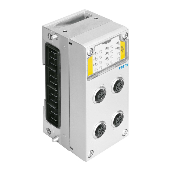
Input module CPX-F8DE-P
Brief description (Translation of the original instructions)
Original: de
. . . . . . . . . . . . . . . . . . . . . . . . . . . . . . . . . . . . . . . . . . . . . . . . . . . . . . . . . . . .
®
CAGE CLAMP
, PI PROFIBUS PROFINET
of the respective trademark owners in certain countries.
1
Safety instructions
Warning
Non-observance of safety regulations can result in death, serious injuries or major
material damage.
• Observe the safety instructions and warnings.
1.1 Intended use
The input module CPX-F8DE-P is intended for use to reliably acquire and evaluate
signals of connected sensors.
The input module provides up to eight secure inputs that can be used in a safety
function by a higher-level safety controller. The communication with the higher-
level safety controller is implemented by the safe protocol PROFIsafe via a fieldbus
connection PROFIBUS or PROFINET IO.
The inputs on the input module can be combined for multi-channel sensor applica-
tions. Every two inputs form a channel pair, which is set separately with one of 11
function modes. These function modes affect the evaluation of input signals, and
optionally on the generation of clock signals.
The characteristics of the inputs correspond to the standard IEC 611312 for type
2 digital inputs.
The input module CPX-F8DE-P is a product with safety-relevant functions. The input
module is intended for installation in machines or automation-technology systems
and may be used only as follows:
– in excellent technical condition
– in its original condition, without unauthorised modifications
– exclusively in the configurations named here (è Section 5.5)
– within the limits of the product defined by the technical data (è Section 7)
– in an industrial environment.
Note
Note that the safety limits of the input module are also its physical limits.
1.2 Rules for product configuration
Operation of the input module CPX-F8DE-P is permissible only in CPX terminals
from Festo.
• Comply with all technical operating limits (è Section 7). Otherwise, operative
malfunctions can occur.
Operation of the CPX-F8DE-P is permissible only in combination with the following
PROFIsafe-capable CPX bus nodes, recognisable on the product label of the bus
node (è Section 2).
Bus node
from revision
1)
CPX-FB13
30
2)
CPX-FB33
21
2)
CPX-M-FB34
21
2)
CPX-M-FB35
21
1) è Description P.BE-CPX-FB13...
2) è Description P.BE-CPX-PN IO...
Fig. 1 Permissible PROFIsafe-capable CPX bus nodes
Festo SE & Co. KG
Postfach
73726 Esslingen
Germany
+49 711 347-0
www.festo.com
8035520
1505NH
[8035522]
®
®
, SIEMENS
are registered trademarks
Network protocol
PROFIBUS
PROFINET IO
PROFINET IO
PROFINET IO
Operation of the CPX-F8DE-P is only permissible with the following connection
blocks:
Connection block
CPX-M-AB-4-M12X2-5POL-T
CPX-M-AB-4-M12X2-5POL
CPX-AB-8-KL-4POL
CPX-AB-ID-P
Fig. 2 Permissible connection blocks
Operation of the CPX-F8DE-P is only permissible with the following interlocking
blocks:
Interlinking block
CPX-M-GE-EV
CPX-M-GE-EV-S-7/8-CI P-4P
CPX-M-GE-EV-S-7/8-5POL
CPX-M-GE-EV-S-PP-5POL
CPX-M-GE-EV-Z-7/8-5POL
CPX-M-GE-EV-Z-PP-5POL
Fig. 3 Permissible interlinking blocks
English
Detailed information about the product, the supported product versions
and required software versions as well as the permissible components of
the CPX terminal can be found in the CPX system description
P.BE-CPX-SYS-... (è www.festo.com/sp).
Information about permissible configurations of the CPX terminal in com-
bination with the input module can also be found in the catalogue
(è www.festo.com/catalogue).
Foreseeable misuse
1.3
The following misuses are not intended use:
– use outdoors
– use in non-industrial areas
– use outside the limits of the product defined in the technical data
– use with inappropriate function modes
– unauthorised modifications.
Note
The use of connection and interlinking blocks that are not specified is not per
missible (è Section 1.2).
Note
In the following cases, the use of the input module CPX-F8DE-P for implementing
of safety circuits is not permissible:
– in a CPX terminal equipped with CPX-FEC or CPX-CEC
– in a CPX terminal of variant P
– in configuration other than those named (è Section 5.5).
Note
In the event of damage caused by unauthorised manipulation or unintended use,
the guarantee is invalidated and the manufacturer is not liable for damages.
1.4 Attainable safety rating
With the CPX-F8DE-P, safety functions can be implemented up to:
– Performance Level e, Cat. 4 in accordance with EN ISO 13849-1
– Safety integrity level SIL 3 in accordance with EN 61508
– Performance limit SIL CL3 in accordance with EN 62061.
The attainable safety level of the overall safety system depends on the set function
mode as well as other components used to implement the safety function.
• Make sure that the overall safety function of the system is analysed and valid-
ated.
It is the responsibility of the operator to determine and document the required
safety rating (safety integrity level, performance level and category) of the sys-
tem.
• Note the residual risks that remain in your system despite the measures to in-
tegrate safety in the design, despite safety precautions and despite the supple-
mentary safety measures.
These residual risks are determined, among other things, by your safety regula-
tions and the safety characteristics of your system.
Application examples
Connection of OSSD sensors with current consumption up to 0.7 A
– Power connection via contacts T0, T2, T4, T6.
Connection of sensors with mechanical switch contacts.
– Clock signals via contacts T0 ... T7.
Connection of OSSD sensors with current consumption up to 2 A.
Connection of sensors via the terminal strip.
Setting of a coded identifier via 8-off DIL switch.
– Connection of sensors is not possible.
Power supply connection
none
Power provided by system; connection: 7/8" (4-pin)
Power provided by system, connection: 7/8" (5-pin)
Power provided by system, connection: push-pull (5-pin)
With separate power supply, connection: 7/8" (5-pin)
With separate power supply, connection: push-pull (5-pin)
Advertisement
Table of Contents

Related Manuals for Festo CPX-F8DE-P


Summary of Contents for Festo CPX-F8DE-P
- Page 1 The following misuses are not intended use: – use outdoors 1.1 Intended use The input module CPX-F8DE-P is intended for use to reliably acquire and evaluate – use in non-industrial areas signals of connected sensors. – use outside the limits of the product defined in the technical data The input module provides up to eight secure inputs that can be used in a safety –...
- Page 2 Only then is operation of the product ensured in accordance with the relevant safety regulations. The product label of the electronics module CPX-F8DE-P (è Fig. 6) includes the • When connecting standard auxiliary components, also observe the specified following information: limit values for temperatures, electrical data and torques.
- Page 3 4.1 Set PROFIsafe address A 10-way DIL switch on the electronics module of the CPX-F8DE-P is used to set an address for PROFIsafe communication. To change this address, disconnect the CPX-F8DE-P.
- Page 4 5.3 I/O image CPX-AB-8-KL-4POL Due to the safety features of PROFIsafe, the input module CPX-F8DE-P occupies Pin allocation X1, X2, X3, X4 Pin allocation X5, X6, X7, X8 7 bytes for outputs and 6 bytes for inputs in the process map of the CPX terminal.
- Page 5 Function mode 3 – 1oo1 T (with clock signal monitoring) Note Circuit diagrams Channel pair ports Comments Malfunctions at unused inputs are possible. Signal evaluation of up to 2 independent • Make sure that function mode 0 is always set for unused channel pairs. single-channel switches/sensors per channel pair with individually clocked sensor supply via T0, T2, T4, T6 and with common clock...
- Page 6 Function mode 5 – 1oo2 (equivalent) Function mode 7 – 1oo2 D (two-hand control device EN 574 type IIIc) Circuit diagrams Channel pair ports Comments Circuit diagram Channel pair ports Comments Signal evaluation of a sensor (typically OSSD), Signal evaluation of 2 independent dual-chan- 24 V 24 V 24 V...
- Page 7 • Always replace the input module if there is an internal error. mode 9 for several channel pairs. • Send the unmodified defective input module, including a description of the error and the application, back to Festo for analysis. Channel pair “1 of 4” circuits...
- Page 8 – Resistance to interference and emitted interference (è www.festo.com/sp) Recommended sensors Function mode UL certification c UL us - Recognized (OL) 1) è Description P.BE-CPX-F8DE-P-..., “Technical data of the connection blocks” Sensors with mechanical switch contacts ² ® ® ®...
Need help?
Do you have a question about the CPX-F8DE-P and is the answer not in the manual?
Questions and answers