Festo CPX-E-EP Translation Of The Original Instructions
Bus module
Hide thumbs
Also See for CPX-E-EP:
- Instructions for use (3 pages) ,
- Manual (52 pages) ,
- Instructions & operating (4 pages)

Related Manuals for Festo CPX-E-EP


Summary of Contents for Festo CPX-E-EP
- Page 1 CPX-E-EP Bus module Description | Function, Parameterisation 8126559 8126559 2020-01a [8126561]...
- Page 2 Translation of the original instructions ® ® ® EtherNet/IP , IO-Link , MODBUS are registered trademarks of the respective trademark owners in certain countries. Festo — CPX-E-EP — 2020-01a...
-
Page 3: Table Of Contents
CPX-E-specific Objects for IO-Link................29 3.1.5 Objects for System Data and Diagnostics............... 31 3.1.6 Force Parameters....................40 3.1.7 Fail Safe and Idle Parameters..................42 Modbus TCP Objects....................45 3.2.1 Commands and Addresses..................45 3.2.2 Status Information (Group A).................. 46 Festo — CPX-E-EP — 2020-01a... - Page 4 3.2.3 Process Data (Group B and D)................47 3.2.4 Diagnostic Memory (Groups C and E)..............58 3.2.5 Modbus TCP Objects (Group F)................60 Technical Data......................60 General Technical Data....................60 Technical Data UL/CSA Certification................62 Festo — CPX-E-EP — 2020-01a...
-
Page 5: About This Document
This document describes the function and parameterisation of the product stated in the title. Safe use of the product is described in a separate document è 1.1 Applicable Documents. Applicable Documents All available documents for the product è www.festo.com/pk. Document Contents... -
Page 6: Product Labelling
About this Document Appropriate software for determining the product version can be found in the Festo Support Portal è www.festo.com/sp. Information on using the software can be found in the integrated Help function. There may be an updated version of this document for these or later product versions è www.festo.com/sp. - Page 7 An access password only protects against unintentional modification. NOTICE! Modules with Ethernet interfaces should only be operated in networks if all connected network com- ponents are supplied by PELV circuits or integrated circuits with equivalent protection. Festo — CPX-E-EP — 2020-01a...
-
Page 8: Function
The bus module is configured in the control software for the higher-order controller using a device description file (EDS file). This contains all the information required to parameterise the system CPX-E via control software (e.g. RSLogix 5000). The current device description file is available on the Festo Support Portal (è www.festo.com/sp). 2.1.3 Crossover Detection (Auto MDI/MDI-X) The product supports crossover detection (auto MDI/MDI-X), which means that there is the option of using patch cables or crossover cables. -
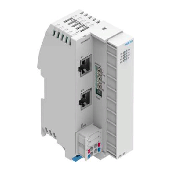
Page 9: Product Design
– Connection/data traffic [XF1]/[XF2] (green) 2 System-specific LED displays: – Operating voltage supply U [PS] (green) EL/SEN – Load voltage supply U [PL] (green) – System error [SF] (rot) – Force mode [M] (yellow) Fig. 3 LED displays Festo — CPX-E-EP — 2020-01a... -
Page 10: Control Elements
DIL switch Function DIL 1: No diagnostics DIL 2: DIL 1: Status bits activated DIL 2: DIL 1: I/O diagnostic interface activated DIL 2: Festo — CPX-E-EP — 2020-01a... -
Page 11: Connecting Elements
The CPX-E system is composed of a different number of inputs and outputs, depending on the number and type of modules CPX-E used and the parameterisation of the bus module. The inputs and outputs are assigned automatically within the system CPX-E. Festo — CPX-E-EP — 2020-01a... -
Page 12: Addressing
– Technology modules – Digital modules 2.3.2 Addressing Example 1 Bus module CPX-E-EP (with status bits) –Status bits activated –I/O diagnostic interface deactivated 2 Digital input module CPX-E-16DI 3 Digital output module CPX-E-8DO 4 Digital output module CPX-E-8DO 5 Analogue input module CPX-E-4AI-U-I 6 Analogue output module CPX-E-4AO-U-I Fig. -
Page 13: Diagnostics Options
Description of the è system CPX-E Network-specific The network status and errors Required link is broken! Target are displayed directly on the module via LED displays. ID_015979b2ed967b98904c43- 870774cdaf-3eb82ebfed967b9- 8904c43870df04bba-en-GB Instructions for è using CPX-E EC Festo — CPX-E-EP — 2020-01a... -
Page 14: Status Bits
1. If all status bits supply a logic 0, there is no error. If, on the other hand, a status bit supplies a logic 1, there is an error. In order to make use of the status bits function, the bus module of the system CPX-E must be configured accordingly. Festo — CPX-E-EP — 2020-01a... -
Page 15: I/O Diagnostics Interface
Number of entries in the diagnostic memory – Trace status 1) specifies whether diagnostic data are present Tab. 11 2.5.2 Diagnostic Steps The necessary steps for performing diagnostics on the system CPX-E are explained below. Festo — CPX-E-EP — 2020-01a... -
Page 16: Diagnostics Via Modbus Tcp
Diagnostic memory è 3.2.4 Diagnostic Memory (Groups C and E) Parameterisation The behaviour of the automation system CPX-E can be parameterised with the aid of suitable software from Festo or using a higher-order controller. Here, a distinction is made between the following vari- ants: –... - Page 17 QoS object Tab. 15 è QoS Object CPX-E-specific Objects for 1 48 IO-Link Port configuration Tab. 23 … è IO-Link object IO-Link Port Configura- tion Object ISDU access object Tab. 24 è ISDU Access Object Festo — CPX-E-EP — 2020-01a...
- Page 18 … 122 123 … 130 131 … CPX-E-specific objects for 1 48 Generic module parameter Tab. 32 … è parameterisation and dia- object Assignment gnostics of the Attributes for Word Parameters to the Function Numbers, Festo — CPX-E-EP — 2020-01a...
- Page 19 Discrete output fail safe 3.1.7 Fail è state object Safe and Idle Discrete output fail safe Parameters mode object Discrete output idle state object Discrete output idle mode object Analogue input force state 3.1.6 è object Force Festo — CPX-E-EP — 2020-01a...
- Page 20 Function output force state object Function output force mode object Function output fail safe 3.1.7 Fail è state object Safe and Idle Function output fail safe Parameters mode object Function output idle state object Festo — CPX-E-EP — 2020-01a...
-
Page 21: Objects For Network Settings
3 = Partial network fault 4 = Rapid fault/restore cycle Ring supervisor active status flag USINT 0 = Backup supervisor 1 = Active ring supervisor 2 = Normal ring node 3 = Non DLR topo Festo — CPX-E-EP — 2020-01a... - Page 22 Bit 6: Reserved, shall be 0 – Bit 7: Flush_table frame capable – Bit 8 31: Reserved, shall be 0 … 1) Bit 0 and bit 1 are mutually exclusive Tab. 14 Device Level Ring Object Festo — CPX-E-EP — 2020-01a...
- Page 23 Bit 2: DHCP client (true) – Bit 3: DHCP-DNS update (false) – Bit 4: Configuration settable (true) – Bit 5: Hardware configurable (true) – Bit 6: Interface configuration change – requires reset (false) – Bit 7: AcdCapable (true) Festo — CPX-E-EP — 2020-01a...
- Page 24 USINT[28] Set (NV) QuickConnect BOOL 0 = Disable 1 = Enable Set (NV) Encapsulation inactivity timeout UINT 0 = Disable 1 3600 = Timeout in seconds (default = 120) … Tab. 16 TCP-IP Interface Object Festo — CPX-E-EP — 2020-01a...
- Page 25 – In Ucast packets – In NUcast packets – In discards – In errors – In unknown protos – Out octets – Out Ucast packets – Out NUcast packets – Out discards – Out errors Festo — CPX-E-EP — 2020-01a...
- Page 26 0 = Unknown interface state 1 = The interface is enabled and ready to send/receive data 2 = The interface is disabled 3 = The interface is testing Set (NV) Admin state USINT 1 = Enable 2 = Disable Festo — CPX-E-EP — 2020-01a...
- Page 27 To set port X1 to 100 Mbps (full duplex) and deactivated auto-negotiation, the values [0002 [0064 ] must be written in attribute 6, instance 1. – To activate auto-negotiation, the values [0001 ] [0000 ] must be written in attribute 6, instance 1. Festo — CPX-E-EP — 2020-01a...
-
Page 28: Objects For I/O Connection
Instance 100 (Output Data) Within instance 100, all outputs of the automation system CPX-E are transmitted cyclically over the network. The following sequence applies during transmission: 1. I/O diagnostic interface or status bits, if activated (16-bit oriented) Festo — CPX-E-EP — 2020-01a... -
Page 29: Cpx-E-Specific Objects For Io-Link
Data type: BYTE – : BYTE – : WORD All data values ARRAY Tab. 22 Instance 102 – Attributes 3.1.4 CPX-E-specific Objects for IO-Link IO-Link Port Configuration Object – Object class: 140 – Instances: 1 … 48 Festo — CPX-E-EP — 2020-01a... - Page 30 Index Subindex Data to write 1) values: 1 = port 1; 2 = port 2; etc. Tab. 24 ISDU Access Object Read response data Write response data Data [0] Data [1 n] Data [0] … Festo — CPX-E-EP — 2020-01a...
-
Page 31: Objects For System Data And Diagnostics
Objects for System Data and Diagnostics Identity Object – Object class: 1 – Instances: 1 Identification and general information on the bus module CPX-E-EP. Service code 5 : Reset • Parameter 0 emulates a power cycle • Parameter 1 resets the device to the factory settings and then emulates a power cycle Attribute no. - Page 32 Bit 10: Major recoverable fault Bit 11: Major unrecoverable fault Bit 12 15: Reserved, shall be 0 … Serial number UDINT Product name (CPX-E-EP remote I/O) SHORT_STRIN- State USINT 0 = Nonexistent 1 = Device self testing 2 = standby...
- Page 33 1 = monitoring U active Bit 4: 0 = SCV monitoring inactive 1 = SCV monitoring Active Bit 5 7: Reserved … – Number of input bytes (Rx size) UINT – Number of output bytes (Tx size) USINT Festo — CPX-E-EP — 2020-01a...
- Page 34 0 = System start with standard paramet- ers (factory setting) and current expan- sion; external parameterisation possible (default) 1 = System start with saved parameters and saved expansion; parameters and expansion are saved to retentive memory; Festo — CPX-E-EP — 2020-01a...
- Page 35 1) Error source = bit 0 … 3; error type = bit 4 … 7 Tab. 29 Status and Diagnostics Object Diagnostics Trace Object – Object class: 134 – Instances: 1 … 40 An instance is created for each entry of a diagnostic message. Festo — CPX-E-EP — 2020-01a...
- Page 36 Tab. 30 Diagnostics Trace Object Diagnostics Trace Status Object – Object class: 135 – Instances: 1 Attribute no. Access Description Type Function number Number of trace entries in the diagnostic BYTE 3482 (bit memory 0 7) … Festo — CPX-E-EP — 2020-01a...
- Page 37 (end of error) Get/Set Error number filter (bit 4, 5) BYTE 3484 (bit 4, 0 = Filter inactive (default) 1 = Record only defined error numbers 2 = Do not record defined error numbers 3 = Reserved Festo — CPX-E-EP — 2020-01a...
- Page 38 Word parameters via the attributes 65 … 127 è Assignment of the Attributes for Word Parameters to the Function Numbers – Double-word parameters via the attributes 129 … 189 è Assignment of the Attributes for Double-Word Parameters to the Function Numbers Festo — CPX-E-EP — 2020-01a...
- Page 39 64 + 9 … × 4828 + m 64 + 10 … × 4828 + m 64 + 11 … × 4828 + m 64 + … × … Festo — CPX-E-EP — 2020-01a...
-
Page 40: Force Parameters
Force mode inputs, technology modules Force state outputs, technology modules Force mode outputs, technology modules Tab. 34 Overview of Force Parameters – Force Mode Objects – Object classes: 109 , 111 , 117 , 119 , 125 , 127 Festo — CPX-E-EP — 2020-01a... - Page 41 Number of channels BYTE All channels: values for Force state ARRAY Tab. 36 Force State Objects for Digital I/O Modules Force State Objects for Analogue I/O Modules – Object classes: 116 , 118 – Instances: 1 … 48 Festo — CPX-E-EP — 2020-01a...
-
Page 42: Fail Safe And Idle Parameters
3.1.7 Fail Safe and Idle Parameters Assigning the instance numbers for the relevant object: • The first word receives the lowest instance number. • The second word receives the second lowest instance number. … • Festo — CPX-E-EP — 2020-01a... - Page 43 BOOL 0 = Hold last state 1 = Fail safe/Idle state Number of channels BYTE All channels: values for Fail safe mode and Idle ARRAY mode Tab. 40 Fail Safe Mode and Idle Mode Objects Festo — CPX-E-EP — 2020-01a...
- Page 44 Tab. 42 Fail Safe State and Idle State Objects for Analogue Output Modules Fail Safe State and Idle State Objects of Technology Modules – Object classes: – Fail safe state: 128 – Idle state: 130 Festo — CPX-E-EP — 2020-01a...
-
Page 45: Modbus Tcp Objects
3.2.1 Commands and Addresses The following table shows the relationship between the Modbus address and the data / parameters of the automation system CPX-E. The data is assigned to different groups. Festo — CPX-E-EP — 2020-01a... -
Page 46: Status Information (Group A)
15 14 13 12 11 10 9 45367 Module 0 15 … 45368 Module 16 31 … 45369 Module 32 47 … 1) 0 = Module not present; 1 = Module present Tab. 46 Configuration of the Automation System CPX-E Festo — CPX-E-EP — 2020-01a... -
Page 47: Process Data (Group B And D)
Bus Module CPX-E-EP Modbus Process data address inputs (Group 15 14 13 12 11 10 9 Result of access to the I/O dia- gnostic inter- face n + 1 Data from the system table (read access) Waiting Festo — CPX-E-EP — 2020-01a... - Page 48 There is a mod- ule error Reserved 1) n = First Modbus address of the module Tab. 49 Process Data Inputs Bus Module CPX-E-EP Modbus Process data address outputs (Group 15 14 13 12 11 10 9...
- Page 49 1) n = First Modbus address of the module 2) Write access occurs with a positive edge (from 0 to 1). Tab. 50 Process Data for Outputs of Bus Module CPX-E-EP Digital Input Module CPX-E-16DI-… Modbus Process data...
- Page 50 Analogue inputs channel n + 3 Analogue inputs channel n + 4 Module dia- gnostic data 1) n = First Modbus address of the module Tab. 54 Process Data Inputs for Analogue Input Module CPX-E-4AI-UI Festo — CPX-E-EP — 2020-01a...
- Page 51 Tab. 56 Process Data Outputs for Analogue Output Module CPX-E-4AO-UI IO-Link Master Module CPX-E-4IOL-… The process image for the input and output data on the IO-Link master module CPX-E-4IOL-… is dependent on the available address space set on the module. Festo — CPX-E-EP — 2020-01a...
- Page 52 Tab. 58 Process Data Outputs for IO-Link Master Module CPX-E-1IOL Modbus Process data address inputs (Group 15 14 13 12 11 10 9 Inputs, channel n + 1 … … n + 7 n + 8 Inputs, channel … … n + 15 Festo — CPX-E-EP — 2020-01a...
- Page 53 Tab. 60 Process Data Outputs for IO-Link Master Module CPX-E-2IOL Modbus Process data address inputs (Group 15 14 13 12 11 10 9 Inputs, channel n + 1 Inputs, channel n + 2 Inputs, channel n + 3 Inputs, channel Festo — CPX-E-EP — 2020-01a...
- Page 54 Tab. 62 Process Data Outputs for IO-Link Master Module CPX-E-4IOL (8 Bytes) Modbus Process data address inputs (Group 15 14 13 12 11 10 9 Inputs, channel n + 1 n + 2 Inputs, channel n + 3 Festo — CPX-E-EP — 2020-01a...
- Page 55 2 n + 5 n + 6 Outputs, chan- nel 3 n + 7 1) n = First Modbus address of the module Tab. 64 Process Data Outputs for IO-Link Master Module CPX-E-4IOL (16 Bytes) Festo — CPX-E-EP — 2020-01a...
- Page 56 3 … … n + 31 n + 32 Module dia- gnostic data 1) n = First Modbus address of the module Tab. 65 Process Data Inputs for IO-Link Master Module CPX-E-4IOL (32 Bytes) Festo — CPX-E-EP — 2020-01a...
- Page 57 + 4 n + 5 Reserved n + 6 Echo outputs n + 7 Module dia- gnostic data 1) n = First Modbus address of the module Tab. 67 Process Data Inputs for Counter Module CPX-E-1CI Festo — CPX-E-EP — 2020-01a...
-
Page 58: Diagnostic Memory (Groups C And E)
Error num- ber filter Mod- ule/chan- nel filter 45653 Module 3485 number 45654 Channel 3486 number 45655 Error num- 3487 45650 Number of 3482 entries in the dia- gnostic memory 45651 Diagnostic 3483 memory overflow Festo — CPX-E-EP — 2020-01a... - Page 59 2 Error end filter Error num- ber filter Mod- ule/chan- nel filter 40262 Module 3485 number 40263 Channel 3486 number 40264 Error num- 3487 1) function number Tab. 70 Parameters and Data (Write Access) Festo — CPX-E-EP — 2020-01a...
-
Page 60: Modbus Tcp Objects (Group F)
+60 – … with vertical mounting position Ambient temperature [°C] 5 +50 – … with horizontal mount- ing position Storage temperature [°C] 20 +70 – … Humidity 0 95 … (non-condensing) Module code (CPX-E-specific) 222/36 Festo — CPX-E-EP — 2020-01a... - Page 61 Reverse polarity pro- tection 24 V U EL/SEN against 0 V U EL/SEN Mains buffering time [ms] Tab. 73 Power Supply Network-specific Data Protocol EtherNet/IP, Modbus TCP Specification EtherNet/IP Transmission rate [Mbps] 10/100 (full duplex/half duplex) Crossover detection Auto-MDI/MDI-X Festo — CPX-E-EP — 2020-01a...
-
Page 62: Technical Data Ul/Csa Certification
EL/SEN Ambient temperature, max. current rating of [°C] 5 +60 5 +50 – … – … terminal strip 4 8 A … > 1) see chapter 'Product design' or 'Connection elements' Tab. 76 Ambient temperature ranges Festo — CPX-E-EP — 2020-01a... - Page 64 Copyright: Festo SE & Co. KG Ruiter Straße 82 73734 Esslingen Germany Phone: +49 711 347-0 Internet: www.festo.com © 2020 all rights reserved to Festo SE & Co. KG...
Need help?
Do you have a question about the CPX-E-EP and is the answer not in the manual?
Questions and answers