
Related Manuals for Thermo Scientific Dionex ICS-5000


Summary of Contents for Thermo Scientific Dionex ICS-5000
- Page 1 Dionex ICS-5000 Ion Chromatography System Operator's Manual Document No. 065342 Revision 06 December 2011...
- Page 2 © 2011 Thermo Fisher Scientific. All rights reserved. AES, Atlas, Chromeleon, IonPac, OnGuard, and SRS are registered trademarks of Thermo Fisher Scientific, Inc. in the United States. Adobe, Acrobat, and Adobe Reader are registered trademarks of Adobe Systems, Incorporated in the United States and other countries. Windows is a registered trademark of Microsoft Corporation in the United states and other countries.
-
Page 3: Table Of Contents
Dionex ICS-5000 System Control ....11 Dionex ICS-5000 System Documentation ..... 14 The Dionex ICS-5000 System Operator’s Manual . - Page 4 Dionex ICS-5000 Operator’s Manual 2.2.6 Static Mixer (Analytical IC only) ..... 27 2.2.7 Pulse Damper (Capillary IC only) ....27 DP/SP Flow Schematics .
- Page 5 Contents 2.13.2 6-Port Valve ........67 2.13.3 10-Port Valve .
- Page 6 Dionex ICS-5000 Operator’s Manual 2.19.4 Waveforms ........105 2.19.5 Storing and Reprocessing Amperometry Data .
- Page 7 Contents 4.3.2 Pretreating Samples ......147 4.3.3 Diluting Samples ....... . . 148 4.3.4 Filling the Autosampler Vials and Loading the Sample Tray .
- Page 8 Dionex ICS-5000 Operator’s Manual 5 • Operation Controlling Modules Directly ......171 Analyzing Samples .
- Page 9 Contents TC Shutdown ..........189 Consumables Storage .
- Page 10 Dionex ICS-5000 Operator’s Manual 7.11 DC Periodic Maintenance ....... . 199 7.12 DC Annual Maintenance .
- Page 11 Contents DP/SP Troubleshooting ........227 8.12 Troubleshooting DP/SP Error Messages ..... 227 8.13 DP/SP Does Not Start .
- Page 12 Dionex ICS-5000 Operator’s Manual 8.28.5 Leak in pH-Ag/AgCl Reference Electrode Compartment . 274 8.28.6 Shift in Ag/AgCl Reference Potential ....274 TC Troubleshooting ........275 8.29 Troubleshooting TC Error Messages .
- Page 13 Contents 9.7.3 Removing the Main Piston Seal ..... 320 9.7.4 Removing the Piston Seal Wash Seal ....321 9.7.5 Installing the Piston Seals and O-Ring .
- Page 14 Dionex ICS-5000 Operator’s Manual 9.15.2 Installing and Flushing the New CR-TC ....350 9.15.3 Completing the New CR-TC Plumbing ....353 9.16 Replacing the RFIC Eluent Degasser .
- Page 15 Contents 9.28.1 Disconnecting the ED Cell ......385 9.28.2 Replacing an ED Cell Disposable Working Electrode Gasket .
- Page 16 Dionex ICS-5000 Operator’s Manual B • Reordering Information DP/SP Reordering Information ......435 EG Reordering Information .
-
Page 17: Introduction
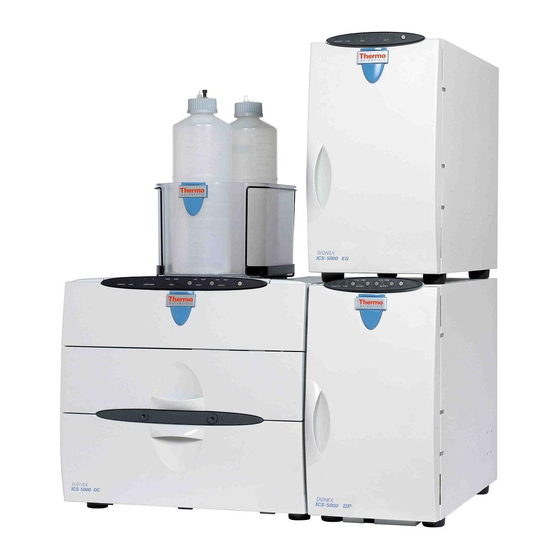
Dionex ICS-5000 Eluent Generator (EG) Dionex ICS-5000 Detector/Chromatography Module ™ Figure 1-1. Dual Dionex ICS-5000 System with RFIC-EG The Thermo Scientific Dionex ICS-5000 Ion Chromatography System offers ™ ™ a full range of Reagent-Free IC (RFIC ) components. RFIC-EG combines automated eluent generation and self-regenerating suppression to make IC easier and more powerful than ever before. -
Page 18: Dionex Ics-5000 System Components
Dionex ICS-5000 System Components The table below identifies modules in the Dionex ICS-5000 product line, as well as additional products that can be added to a Dionex ICS-5000 system. Refer to the page number indicated here for a brief product overview. - Page 19 Mass Spectrometer MSQ Plus page 10 Dionex ICS-5000 Dual Pump (DP) and Dionex ICS-5000 Single Pump (SP) Each Dionex ICS-5000 pump can be configured for either capillary IC applications or analytical (standard bore and microbore) IC applications. Capillary IC pumps are always isocratic (they deliver one eluent). Analytical IC pumps can be either isocratic or low pressure proportioned gradient.
- Page 20 Dionex ICS-5000 Operator’s Manual The second pump in the DP can be operated as a second-channel chromatography pump, an auxiliary dependent pump, or an auxiliary independent pump. Capillary IC pumps operate at flow rates ranging from 0.001 to 3.0 mL/min...
- Page 21 21 MPa (3000 psi) with RFIC. Both microbore and standard bore IC applications are supported. Dionex ICS-5000 Eluent Generator (EG) The EG generates high purity acid or base eluents online from deionized water. The EG can be configured for single- or dual-channel operation. Each channel includes: •...
- Page 22 ™ Reagent-Free IC with Eluent Regeneration (RFIC-ER RFIC-ER is available as an option for Dionex ICS-5000 systems without an EG. Eluent regeneration uses the suppressor to reconstitute the starting eluent, allowing use of a single 4-liter bottle of eluent for up to four weeks. Because the system is a closed loop, it can run continuously, eliminating the need for recalibration or re-equilibration during the 28 days of non-stop operation.
- Page 23 1 • Introduction Dionex ICS-5000 Detector/Chromatography Module (DC) The DC provides a temperature-controlled environment for Dionex ICS-5000 chromatography components. The DC can accommodate components for two channels, plumbed either serially or in parallel. The following components may be installed in the DC: •...
- Page 24 The AM is installed in the upper compartment of the DC, above the detector. Dionex ICS-5000 Thermal Compartment (TC) The TC provides a temperature-controlled environment for Dionex ICS-5000 chromatography components. The TC is intended for applications that do not require conductivity or electrochemical detection.
- Page 25 5.0 mL of sample (in 0.1 mL increments) to the sample loop or concentrator column in an ion chromatography system. The Dionex ICS-5000 holds 50 vials (either 0.5 mL or 5.0 mL, or a combination of the two sizes). Vials can be sampled in any order and multiple samples can be taken from each vial.
- Page 26 Dionex ICS-5000 Operator’s Manual chromatograms at individual wavelengths instead of from spectra offers two advantages: it eliminates the need to perform extractions for chromatograms that do not require spectral data and it conserves disk space. Dionex ICS Series Variable Wavelength Detector (VWD) The VWD is a dual-beam, variable wavelength photometer with one measurement and one internal reference beam.
-
Page 27: Dionex Ics-5000 System Control
1 • Introduction 1.1.2 Dionex ICS-5000 System Control The Dionex ICS-5000 system is controlled by a PC configured with Thermo ™ Scientific Dionex Chromeleon 7 Chromatography Data System (release 7.0 SR1 or later) or Thermo Scientific Dionex Chromeleon 6.8 Chromatography Data System (release 6.8 SR9a or later). - Page 28 Dionex ICS-5000 Operator’s Manual the Home panel in Chromeleon 7 and Figure 1-3 shows the Home panel in Chromeleon 6.8 Figure 1-2. Chromeleon 7 ePanel Set (Dionex ICS-5000 Home Panel Shown) Doc. 065342-06 12/11...
- Page 29 1 • Introduction Figure 1-3. Chromeleon 6.8 Panel Tabset (Dionex ICS-5000 Home Panel Shown) Doc. 065342-06 12/11...
-
Page 30: Dionex Ics-5000 System Documentation
Dionex ICS-5000 Operator’s Manual Dionex ICS-5000 System Documentation Every effort has been made to provide complete and accurate user documentation for the Dionex ICS-5000 system. The table below lists the primary sources of product information and the formats in which information is available. -
Page 31: The Dionex Ics-5000 System Operator's Manual
These manuals are provided on the Reference Library DVD. The Dionex ICS-5000 System Operator’s Manual The electronic version (i.e., PDF file) of the Dionex ICS-5000 system operator’s manual contains numerous links that you can click to go to other locations within the manual. -
Page 32: Safety And Regulatory Information
ICS-5000 system is designed for IC (ion chromatography) and HPLC (high- performance liquid chromatography) applications and should not be used for any other purpose. Operation of a Dionex ICS-5000 module in a manner not specified by Thermo Fisher Scientific may result in personal injury. - Page 33 1 • Introduction Indicates a potentially hazardous situation which, if not avoided, could result in death or serious injury. Indicates a potentially hazardous situation which, if not avoided, may result in minor or moderate injury. Also used to identify a situation or practice that may seriously damage the instrument, but will not cause injury.
-
Page 34: Safety Symbols
If a section is not flagged, the information in the section applies to both capillary IC and analytical IC systems. 1.4.2 Safety Symbols These symbols appear on the Dionex ICS-5000 modules or on labels affixed to the modules: Alternating current Primary protective conductor terminal... -
Page 35: Declaration Of Conformity
1 • Introduction 1.4.3 Declaration of Conformity The cETLus or cTUVus and CE marks on the model/data labels on each Dionex ICS-5000 module indicate that the modules are in compliance with the following standards. Doc. 065342-06 12/11... -
Page 36: Deionized Water Requirements For Ic
Dionex ICS-5000 Operator’s Manual Deionized Water Requirements for IC For eluent generation or when manually preparing eluent and regenerant, use ASTM Type I (18 megohm-cm) filtered and deionized water that meets the specifications listed in Table 1-1. Contaminant Specification Ions–Resistivity >18.0 (megohm-cm) -
Page 37: Description
DP/SP DP/SP Front Features A status bar on the front of the Dionex ICS-5000 Dual Pump (DP) and Dionex ICS-5000 Single Pump (SP) includes buttons for controlling certain pump functions, as well as LEDs (light emitting diodes) that indicate the status of... - Page 38 Dionex ICS-5000 Operator’s Manual Button/LED If the LED Is On If the LED Is Flashing Label CONNECTED The DP/SP is connected to Does not flash. a Chromeleon 7 instrument or Chromeleon 6.8 timebase. ALARM A DP/SP-related problem Does not flash.
-
Page 39: Dp/Sp Interior Components
2 • Description DP/SP Interior Components The pump’s mechanical components are located directly behind the front door of the module. Figure 2-3 shows the mechanical components of a DP that contains a gradient analytical pump (pump 1) and an isocratic capillary pump (pump 2). -
Page 40: Pump Heads
Dionex ICS-5000 Operator’s Manual Vacuum Degas Chambers (four channels) Proportioning Valve Fittings Proportioning Valve Outlet to Primary Pump Head Static Mixer Pump Outlet to EG or Injection Valve Figure 2-4. Analytical Gradient Pump Components NOTE For easier access to pump components when performing ser- vice procedures, the pump panel can be pulled forward to the front of the pump compartment. -
Page 41: Pressure Transducer
2 • Description the pulsation increases as the operating pressure increases, because part of the delivery stroke is required to compress eluent in the pump head. During the pre-compression phase, pulsation is minimized. A patented secondary control system (automatic compressibility compensation) ensures highly constant eluent delivery. -
Page 42: Piston Seal Wash System
Dionex ICS-5000 Operator’s Manual • The electronics required to operate the vacuum pump • Tubing, fittings, and other accessories The vacuum degassing module is automatically activated when the DP/SP power is turned on. Allow about 10 minutes for the module to equilibrate. -
Page 43: Static Mixer (Analytical Ic Only)
2 • Description necessary, connect the seal wash system to pump 2 (the top pump), instead. For instructions on how to replumb the system, refer to Section 4.7. NOTE For users who need to operate a piston seal wash system for both pumps in the DP, Thermo Fisher Scientific offers an External Seal Wash Kit (P/N 063518) or a second seal wash system (P/N 068661). -
Page 44: Dp/Sp Flow Schematics
Dionex ICS-5000 Operator’s Manual DP/SP Flow Schematics 2.3.1 Isocratic Pump Flow Schematic Figure 2-5 illustrates the liquid flow path through an isocratic pump. OUTLET CHECK VALVE DI WATER ELUENT SECONDARY PRIMARY PUMP PUMP HEAD HEAD INLET VACUUM CHECK VALVE DEGAS... -
Page 45: Gradient Pump Flow Schematic
2 • Description 2.3.2 Gradient Pump Flow Schematic Figure 2-6 illustrates the liquid flow path through a gradient pump. OUTLET ELUENT ELUENT ELUENT ELUENT CHECK VALVE SECONDARY PRIMARY PUMP PUMP HEAD HEAD INLET CHECK VALVE VACUUM DEGAS STATIC MIXER PROPORTIONING VALVE TO ELUENT GENERATOR OR INJECTION VALVE... -
Page 46: Dp/Sp Rear Panel
Dionex ICS-5000 Operator’s Manual DP/SP Rear Panel Figure 2-1 illustrates the rear panel of the DP/SP. Tubing Chase (2) Main Power Switch, Fuse Holder, and Power Receptacle Digital I/O Port Analog Pressure Output USB Receptacle (“B” Connectors) USB Ports (3) (“A”... - Page 47 2 • Description NOTE POWER For routine on/off control, use the button on the front of the DP/SP (see Figure 2-1 Figure 2-2). To turn off the POWER pump, press and hold the button for 2 seconds. The fuse cartridge contains two 2-amp IEC 60127-2 slow-blow fuses (P/N 954773).
- Page 48 Dionex ICS-5000 Operator’s Manual Pin Number Signal Name Signal Level Description Relay 2 Out Potential-free Common Ground Ground Ground Ground Ground Ground Ground Ground ----- ----- Not used Relay 4 Out Potential-free Normally open Relay 4 Out Potential-free Common Relay 4 Out...
- Page 49 PC on which Chromeleon is installed. • Three USB (Universal Serial Bus) ports (“A” type connectors) are provided for connections to other Dionex ICS-5000 modules. One 1.8 m (6 ft) USB cable (P/N 960777) is provided in the pump ship kit: Pump Ship Kit...
-
Page 50: Eluent Reservoirs
2.5.1 EO (Optional) The Dionex ICS-5000 Eluent Organizer (EO) holds eluent reservoirs in a liner that contains spills and leaks. Up to two EOs can be installed on top of the DC. Each EO accommodates up to four 1-liter or 2-liter reservoirs or up to two 4-liter reservoirs. - Page 51 If more reservoirs are required, order a second regulator (P/N 074423). For instructions on installing the regulator kits, refer to Thermo Scientific Dionex ICS-5000 Ion Chromatography System Installation Instructions (Document No. 065343). The manual is included on the Thermo Scientific Reference Library DVD (P/N 053891).
-
Page 52: Filtering Eluent
Dionex ICS-5000 Operator’s Manual 2.5.3 Filtering Eluent • Install an end-line filter (P/N 045987) on the end of each reservoir’s eluent line. End-line filters are provided in the pump ship kit. • A Dionex High-Pressure Inline Filter (P/N 044105) can be used to remove particulates down to 0.45 micron from eluent. -
Page 53: Eg Description
EG Description EG Front Features The status bar on the front of the Dionex ICS-5000 Eluent Generator (EG) includes buttons that provide control of certain EG functions, as well as LEDs that indicate the status of several EG functions (see Figure 2-8). -
Page 54: Eg Interior Components
Dionex ICS-5000 Operator’s Manual Button/LED If the LED Is On Comment Label POWER Use this POWER button for The main power switch is on routine on/off control of the the EG rear panel. EG. When the power is on, this LED is lighted. To turn off... - Page 55 2 • EG Description To access components for maintenance or service procedures, push down on the slide release latch and pull the tray forward until it reaches the stop. EGC (Capillary) Chase for Electrical Cables CR-TC (Capillary) Leak Sensor Drip Tray Slide Release Latch Note: For a capillary IC...
- Page 56 Dionex ICS-5000 Operator’s Manual EGC III (Analytical) RFIC Eluent Degasser (for Analytical IC only) Electrical Cables CR-TC (Analytical) Drip Tray Slide Release Latch Figure 2-10. Example EG Interior Components for an Analytical IC System (System 2 of a Dual-Channel EG Shown)
- Page 57 IC system cannot be used in an analytical IC system, and vice versa. Analytical IC systems require EGC III cartridges and (if used) the EPM III Electrolytic pH Modifier. Previous versions of EGC or EPM are not compatible with the Dionex ICS-5000 Eluent Generator. EGC Version Part Function...
- Page 58 Dionex ICS-5000 Operator’s Manual For more information, refer to the EGC manual. The manual is included on the Thermo Scientific Reference Library DVD (P/N 053891). Continuously Regenerated Trap Column (CR-TC) The CR-TC is a high pressure, electrolytically- regenerated trap column. The CR-TC is designed to...
- Page 59 KHCO eluent. For more information about these products, refer to the EGC manual. EGC manuals are included on the Thermo Scientific Reference Library DVD (P/N 053891). Leak Sensor If liquid collects in the drip tray in the bottom of the EG, a leak sensor reports the leak to Chromeleon, and an error message is displayed in the Audit Trail.
- Page 60 Dionex ICS-5000 Operator’s Manual Electrical Connections Electrical connectors provide a connection from the components installed in the EG to the EG power supplies. There are two sets of electrical connectors (one per channel). Connections for the following components are provided: •...
-
Page 61: Eg Rear Panel
2 • EG Description EG Rear Panel Figure 2-12 illustrates the rear panel of the Dionex ICS-5000 Eluent Generator (EG). Exhaust Fan Gas Vent Lines USB Receptacle (“B” Connector) USB Ports (2) (“A” Connectors) Fuse Holder, Main Power Switch, and Power... - Page 62 Dionex ICS-5000 Operator’s Manual One 1.8 m (6 ft) USB cable (P/N 960777) is provided in the EG Ship Kit (P/N 072047). Fuse Holder, Main Power Switch, and Power Receptacle The fuse cartridge contains two 2-amp slow-blow fuses (P/N 954773). For...
-
Page 63: Eg Flow Schematics
2 • EG Description • The drain port removes any liquid that collects in the drip tray in the bottom of the EG. A clear corrugated drain hose (P/N 055075) is connected to this port during installation. Place the free ends of the vent lines and drain hose into a waste container. To maintain a positive siphon, position the waste container below the level of the For correct drainage, make sure the vent lines and drain hose are not bent, pinched, or elevated at any point. - Page 64 Dionex ICS-5000 Operator’s Manual Vent (Capillary) TO PUMP/DAMPER WASTE, GAS SEPARATOR To CR-TC Regen Out Degas (blue label) Cartridge (inside DC) To CR-TC To CR-TC REGEN OUT Eluent Out Eluent In (yellow label) (red label) To EG Degas Regen Out...
- Page 65 Figure 2-14. EG Flow Schematic Example for Analytical IC NOTE Refer to the EGC-CO Mixer manual for a flow schematic showing the components required to generate a carbon- ate/bicarbonate mixture. The manual is included on the Thermo Scientific Reference Library DVD (P/N 053891). Doc. 065342-06 12/11...
- Page 66 Dionex ICS-5000 Operator’s Manual Doc. 065342-06 12/11...
-
Page 67: Dc Description
ICS-5000 DC Description 2.10 DC Front Features The status bar on the front of the Dionex ICS-5000 Detector/Chromatography Module (DC) (see Figure 2-15) includes buttons for controlling certain DC functions, as well as LEDs that indicate the status of several DC components and functions. - Page 68 Dionex ICS-5000 Operator’s Manual Button/LED If the LED Is On If the LED Is Flashing Label VALVE 1 LOAD Use the VALVE 1 and VALVE 2 Valve error. See VALVE 2 LOAD buttons to manually switch the Section 8.25 position of the DC injection troubleshooting.
-
Page 69: Dc Interior Components
2 • DC Description injection, the DC can be connected to an autosampler. For more information about sample injection, see Section 5.2. Sample Loading Ports Figure 2-16. DC Sample Loading Ports 2.11 DC Interior Components The interior of the DC consists of two temperature controlled compartments (upper and lower). -
Page 70: Dc Interior Components For Capillary Ic
2.11.2. The tray slides forward for easy access to components. • The lower section houses either one or two Dionex ICS-5000 Conductivity Detectors (CDs), one or two Dionex ICS-5000 Electrochemical Detectors (EDs), or one detector of each type. For details... -
Page 71: Ic Cube For Capillary Ic
Cube is installed in the upper compartment of the DC. For a dual-system, two IC Cubes can be installed. NOTE When an IC Cube is installed, a Dionex ICS-5000 Automa- tion Manager cannot be included in the DC. Each IC Cube includes an injection valve, a column heater, and four component cartridges that slide into the housing. - Page 72 Dionex ICS-5000 Operator’s Manual Cartridges for the following components are available: carbonate removal device (CRD); suppressor, guard and separator columns; and EG degasser. NOTE If the IC Cube does not include a CRD or suppressor, bypass cartridges must be installed. Bypass cartridges provide the internal plumbing connections required for eluent and regen- erant flow between IC Cube components.
- Page 73 When the cartridge is installed in the IC Cube, pins on the rear of the cartridge connect the suppressor to its power source. For details about the suppressors, refer to the suppressor manuals. The manuals are on the Thermo Scientific Reference Library DVD (P/N 053891).
- Page 74 Dionex ICS-5000 Operator’s Manual Column Heater and Column Cartridge Capillary The IC Cube column heater provides a temperature-controlled compartment for the capillary guard and separator columns. The heater temperature range is from 5 °C above the temperature of the upper DC compartment to 80 °C.
- Page 75 2 • DC Description IC Cube Eluent and Regenerant Flow Capillary The numbers on the schematic shown in Figure 2-19 indicate the flow path of eluent and regenerant through the plumbing connections on an IC Cube configured for conductivity detection. ELUENT IN ELUENT IN REGEN OUT...
- Page 76 Dionex ICS-5000 Operator’s Manual The numbers on the schematic shown in Figure 2-20 indicate the flow path of eluent and regenerant through the plumbing connections on an IC Cube configured for electrochemical detection. ELUENT IN REGEN OUT ELUENT OUT ELUENT OUT...
-
Page 77: Dc Interior Components For Analytical Ic
Section 2.18 for details about the AM. • The lower section houses either one or two Dionex ICS-5000 Conductivity Detectors (CDs), one or two Dionex ICS-5000 Electrochemical Detectors (EDs), or one detector of each type. For details about the CD, see Section 2.14. - Page 78 Dionex ICS-5000 Operator’s Manual Suppressors for conductivity detection are also installed in the upper compartment. The following types of suppressors can be used: ™ • Thermo Scientific Dionex SRS 300 Self-Regenerating Suppressor (2 and 4 mm) ™ ™ • Thermo Scientific Dionex AES...
-
Page 79: Dc Temperature Control Zones
2 • DC Description 2.12 DC Temperature Control Zones The following temperature control zones are possible with the DC, depending on the options installed: • DC upper compartment • DC lower compartment • Heated conductivity cell • IC Cube capillary column heater Capillary •... - Page 80 Dionex ICS-5000 Operator’s Manual Minimum temperatures are also affected by the ambient humidity. If the humidity is high, the minimum temperatures achieved for a temperature zone is not as low as those achieved in a low ambient humidity environment. NOTE A DC Temperature Calibration Kit (P/N 063782) is available.
-
Page 81: High-Pressure Valves
2 • DC Description 2.13 High-Pressure Valves Up to four high-pressure valves can be installed in the DC. The following valve models are available: 4-port (P/N 074525), 6-port (P/N 061961), and 10-port (P/N 061962). In a capillary IC system, one 4-port high-pressure valve is installed on each IC Capillary Cube. -
Page 82: 4-Port Valve
Dionex ICS-5000 Operator’s Manual 2.13.1 4-Port Valve The 4-port valve (P/N 074525 is the standard injection valve for capillary IC systems. It is installed in the IC Cube (see Figure 2-18). The valve has a L internal sample loop. -
Page 83: 6-Port Valve
2 • DC Description 2.13.2 6-Port Valve The 6-port valve (P/N 061961) is the standard injection valve for analytical IC systems. It is installed in the lower compartment of the DC (see Figure 2-21). Figure 2-25 shows flow schematics for the 6-port valve. LOAD POSITION INJECT POSITION Sample... -
Page 84: 10-Port Valve
Dionex ICS-5000 Operator’s Manual 2.13.3 10-Port Valve The 10-port valve (P/N 061962) is an optional valve, available for various applications. Figure 2-26 shows example flow schematics for the 10-port valve when it is connected for an application that uses a concentrator column. -
Page 85: Cd Conductivity Detector
2.14 CD Conductivity Detector Each Dionex ICS-5000 Conductivity Detector (CD) consists of a heated conductivity cell and the electronics required for collecting the conductivity data and sending it to the computer and the analog output (if installed). The... - Page 86 Dionex ICS-5000 Operator’s Manual cycling in the baseline. This, in turn, can affect the reproducibility of an analysis. The higher the conductivity, the more pronounced the effect. To reduce the effect of temperature variation, the DC provides temperature control of both the DC compartment and the cell. A heater inside the cell regulates the cell temperature.
-
Page 87: Suppressor
™ For details about any of the suppressors, including guidelines for selecting a suppressor for your application, refer to the suppressor manuals. The manuals are on the Thermo Scientific Reference Library DVD (P/N 053891). Capillary IC Suppressor Capillary The suppressor for a capillary IC system is installed inside an IC Cube capillary suppressor cartridge. -
Page 88: System Flow Schematics For Conductivity Detection
NOTE It is also possible to control an analytical suppressor with a Dionex ICS-5000 Electrochemical Detector (ED). Tabs for installing the suppressor are provided on the front of the DC (next to the ED). The cable connection is the same as for the... - Page 89 2 • DC Description COND CELL For anion suppression only (optional). REGEN SUPPRESSOR SEPARATOR COLUMN GUARD SAMPLE TEMP STABILIZER Eluent Flow Regenerant Flow For analytical IC only PUMP or WASTE VALVE ELUENT (Inject Position) ELUENT IN GENERATOR Figure 2-28. DC Flow Schematic for Conductivity Detection (Suppression in Recycle Mode) •...
- Page 90 Dionex ICS-5000 Operator’s Manual chamber. Flow is again routed through the CRD (if installed) and then to waste Figure 2-29 illustrates the flow path through an EG and a DC for a conductivity detection application using suppression in recycle mode.
-
Page 91: Ed Electrochemical Detector
2.15 ED Electrochemical Detector One or two Dionex ICS-5000 Electrochemical Detectors (EDs) can be installed in the DC. Each complete ED assembly consists of an amperometric detection cell and the detector electronics required to collect data and send it to the computer and the analog output (if installed). - Page 92 Dionex ICS-5000 Operator’s Manual The ED cell can be used in either capillary IC or analytical IC systems. When used in a capillary IC system, the inlet tubing is made of PEEK. When used in an analytical IC system, the inlet tubing is made of titanium (see Figure 2-30).
-
Page 93: Combination Ph-Ag/Agcl Reference Electrode
2 • DC Description the carbonate removal step during monosaccharide and disaccharide chromatography) at high hydroxide concentrations do not affect the electrode performance. If sustained highly alkaline eluent conditions are required, use a disposable gold electrode on a PTFE substrate or a conventional gold electrode. - Page 94 Dionex ICS-5000 Operator’s Manual applied to the working electrode must be raised approximately 0.3 V when switching from the “Ag” reference to the “pH” reference. In acidic eluents, the reference potential of the pH half-cell is positive with respect to the Ag/AgCl half-cell, and all applied potentials must be decreased by 0.059 V per pH unit when switching from the “Ag”...
-
Page 95: Palladium Hydrogen (Pdh) Reference Electrode
2 • DC Description 2.15.3 Palladium Hydrogen (PdH) Reference Electrode The PdH reference electrode consists of palladium and platinum electrodes immersed in an aqueous solution. With a potential applied between the two electrodes, palladium is connected as a cathode and platinum as an anode. As a consequence of the applied potential, hydrogen gas is generated at the palladium electrode and oxygen gas at the platinum electrode. -
Page 96: Dc Rear Panel
Dionex ICS-5000 Operator’s Manual reference electrode, it cannot indicate pH. In the same manner, a glass electrode alone cannot measure pH; it must be used with a suitable reference electrode. The pH readout of the ED cell is disabled when the PdH reference mode is selected. - Page 97 2 • DC Description Switched AC Sockets The two AC receptacles can be used to control the power to external devices. Use Chromeleon to switch the power on and off. TTL inputs can also be used to control the AC sockets (see Section 2.17.4).
- Page 98 Dionex ICS-5000 Operator’s Manual External Low Pressure Valve Outputs Six outputs allow connection to externally-installed low-pressure (solenoid) valves. Low-pressure valves can be used for on/off control of liquid flow (for example, to turn flow on and off from a reagent reservoir). You control the outputs with Chromeleon.
-
Page 99: I/O Option
2 • DC Description 2.17 I/O Option When the I/O option (P/N 062201) is installed, two 12-pin connector strips are on the DC rear panel. Figure 2-32 describes the functions assigned to each connector pin. Figure 2-32. Optional Rear Panel I/O Connector Strips Doc. -
Page 100: I/O Option Connections
Dionex ICS-5000 Operator’s Manual 2.17.1 I/O Option Connections 1. Locate the twisted pair of wires (P/N 043598) and 12- Position 1 position connector plugs Locking (P/N 923686) (see Screws Figure 2-33) provided with the I/O option board. Position 12 Figure 2-33. -
Page 101: Analog Outputs
2 • DC Description 2.17.2 Analog Outputs When the I/O option is installed, two analog outputs (one for each detector) are installed on the DC rear panel (see Figure 2-31). The analog outputs supply a voltage signal proportional to the current measured by the detector cell. - Page 102 Dionex ICS-5000 Operator’s Manual Analog Output Values Description Setting Recorder Zero, Full Scale, Use this setting to calibrate a calibration Normal recording device. Select Zero to set the output signal to zero volts. Select Full Scale to set the output signal to the selected full- scale voltage (0.01, 0.10, or...
-
Page 103: Power, Relay, And Ttl Outputs
2 • DC Description Figure 2-34. Conductivity Detector Control Panel (Chromeleon 7 Version Shown) 2.17.3 Power, Relay, and TTL Outputs The power, relays, and TTL outputs can be used to control functions in external devices such as an autosampler or another Dionex module. Depending on which pins are connected, the relay connection can be either normally open (N.O.) or normally closed (N.C.) (see Figure... - Page 104 Dionex ICS-5000 Operator’s Manual The relays can be programmed to switch any low-voltage device. Switched current must be no more than 2 A at 24 VDC. Refer to Section 2.17.1 and the documentation for the external device for connection instructions.
-
Page 105: Ttl Inputs
2 • DC Description You can control the power, relays, and TTL outputs from the DC ePanel in Chromeleon 7 (see Figure 2-36) or the DC Control panel in Chromeleon 6.8. Figure 2-36. Output Relays and TTL Control on DC ePanel in Chromeleon 7 NOTE It is possible to change the settings for the power, relays, and TTL outputs while a Chromeleon 7 instrument method or... - Page 106 Dionex ICS-5000 Operator’s Manual • ED detectors 1 and 2 (on/off) • CD/ED detectors 1 and 2 auto-offset • CD/ED detectors 1 and 2 mark • Suppressors 1 and 2 (on/off) • Reaction coil heater (on/off) • A/C relays 1 and 2 (open/closed)
- Page 107 2 • DC Description 3. Select the TTL Inputs tab (see Figure 2-37). Figure 2-37. DC Server Configuration Properties: TTL Inputs 4. Select the name of the input and press the F2 key (or double-click the name). Doc. 065342-06 12/11...
- Page 108 Dionex ICS-5000 Operator’s Manual The Device Configuration dialog box for the selected input appears. Figure 2-38. Assign TTL Input Control Functions 5. In the Control Functions list, select the check box of one or more functions to be controlled by this input. When connected to a controlling device, the device can send a signal to the input to trigger the selected functions.
- Page 109 2 • DC Description controlling device and the information below to determine the correct type. Select the input control type in the Device Configuration dialog box for each TTL input (see Figure 2-38). • Normal Edge: In normal edge Action Off or No Effect operation, the negative (falling) +5 V edge of a signal turns on the...
-
Page 110: Automation Manager
Dionex ICS-5000 Operator’s Manual 2.18 Automation Manager The Dionex ICS-5000 Automation Manager (AM) provides a mounting location for various components used for performing matrix elimination, large volume pre-concentration, post-column reagent addition, and other functions. Each AM consists of a tray on which valves and other components are... - Page 111 2 • DC Description Components Included Part Number One 6-port high-pressure valve 061740 One low-pressure 3-way valve AutoPrep configuration: 066343 10-port high-pressure valve AutoPrep sample loop AutoPrep standard loops AM tray with no valves 061734 Figure 2-40. AM Configurations (Continued) In addition to the configurations described above, you can order the following components separately for installation on an AM: AM Component...
-
Page 112: Am High-Pressure Switching Valves
Dionex ICS-5000 Operator’s Manual 2.18.1 AM High-Pressure Switching Valves Up to two high-pressure switching valves can be installed on an AM. Two models are available: 6-port (P/N 061961) and 10-port (P/N 061962). Both models are electrically-activated, two-position valves. Figure 2-42... -
Page 113: Am Low-Pressure Valves
2 • DC Description 2.18.2 AM Low-Pressure Valves Up to two low-pressure valves can be mounted on an AM. The valves are either two-way or three-way valves. The two-way valves provide on/off control of liquid flow in one direction, while the three-way valves provide on/off control in two directions (see Figure 2-44). -
Page 114: Am High- And Low-Pressure Valve Control
Dionex ICS-5000 Operator’s Manual 2.18.3 AM High- and Low-Pressure Valve Control Chromeleon is used to control the high- and low-pressure valves. For automated control, commands for valve control can be included in a Chromeleon 7 instrument method or a Chromeleon 6.8 program. To add AM... - Page 115 2 • DC Description To add AM valve control commands to a Chromeleon 6.8 program, use the Relay and State Devices Options page in the Program Wizard (see Figure 2-46). Figure 2-46. Chromeleon 6.8 Program Wizard Relay and State Devices Options Page Doc.
- Page 116 Dionex ICS-5000 Operator’s Manual For manual control of AM valves, execute commands from the DC ePanel in Chromeleon 7 (see Figure 2-47) or the DC Control panel in Chromeleon 6.8. Figure 2-47. Valve Control on DC ePanel in Chromeleon 7...
-
Page 117: Reaction Coil Heater
2 • DC Description 2.18.4 RCH-1 Reaction Coil Heater The RCH-1 Reaction Coil Heater (P/N 061746) can hold up to two reaction coils. The heater has an operating temperature range of from 5 °C above the temperature of the upper compartment up to 80 °C. For automated control of the heater, commands can be included in a Chromeleon 7 instrument method (see Figure... -
Page 118: Electrochemical Detection Modes
Dionex ICS-5000 Operator’s Manual 2.19 Electrochemical Detection Modes The Dionex ICS-5000 Electrochemical Detector can perform the following electrochemical detection modes: • DC amperometry (see Section 2.19.1) • Integrated amperometry—includes pulsed amperometric detection (PAD) and integrated pulsed amperometric detection (IPAD) (see Section 2.19.2) -
Page 119: Integrated And Pulsed Amperometric Detection
2 • DC Description capacity, which is determined by the length of the run and the data sampling rate. For direct control, enter the potentials on the DC ePanel in Chromeleon 7 or the Control panel in Chromeleon 6.8. 2.19.2 Integrated and Pulsed Amperometric Detection Integrated and pulsed amperometric detection are similar to DC amperometry (see Section... - Page 120 Dionex ICS-5000 Operator’s Manual measured by integrating the current for a fixed time. Current integrated for a fixed time is charge and the units are coulombs. At t2 and t3, positive and negative cleaning pulses are added to the waveform. This waveform period repeats until the end of data acquisition or until another waveform is specified.
-
Page 121: Cyclic Voltammetry
2 • DC Description 2.19.3 Cyclic Voltammetry The determination of the optimum potentials to use in amperometry begins with an electrochemical technique called voltammetry, in which the current that results from oxidation or reduction reactions is measured against the voltage applied to the system. The applied voltage is changed (scanned) within preset limits. - Page 122 Dionex ICS-5000 Operator’s Manual Figure 2-52 shows an example of a triangular waveform used in cyclic voltammetry. (14.0, 0.60) 0.60 0.40 0.20 0.00 Volts 0.00 5.00 10.00 15.00 20.00 25.00 30.00 -0.20 -0.40 -0.60 (0.00, -0.80 (28.0, -0.80) -0.80 Seconds Figure 2-52.
- Page 123 2 • DC Description Cyclic voltammetry waveforms are defined manually on the Chromeleon 6.8 electrochemical detector Control panel. Click the CV Mode button to display the following window. Figure 2-53. Cyclic Voltammetry Control Panel Integrated Amperometry Waveforms Integrated amperometry waveforms are included in an instrument method in Chromeleon 7 or a program in Chromeleon 6.8.
- Page 124 Dionex ICS-5000 Operator’s Manual Chromeleon provides several pre-programmed waveforms. You can use a pre-programmed waveform, without modification, or modify it for your application. You can also define a new waveform. Waveforms are defined and modified in the Waveform Editor (see Figure 2-54).
-
Page 125: Storing And Reprocessing Amperometry Data
2 • DC Description With scanning waveforms, integration occurs while the potential is being increased linearly over time (see the example scanning waveform in Figure 2-55). Although scanning waveforms are typically not as useful for quantitative analysis as analytical waveforms, when used to collect 3D amperometric data, scanning waveforms can be optimized to provide characteristic I-t plots (see Section... - Page 126 Dionex ICS-5000 Operator’s Manual time (in minutes) is on the x-axis and the detector response (in nanoCoulombs) is on the y-axis. Analytical Column: CarboPac PA10 (4 x 250 mm) and Guard Eluent: 18 mM NaOH Flow Rate: 1.5 mL/min Detection:...
- Page 127 2 • DC Description double-click the sample in the Browser to open the chromatogram. On the View menu, click 3D-Amperometry. Sample Chromatogram Injection Data Plot* I-t Plot 3D Amperometry (current vs. Data Plot waveform time) Waveform Plot Figure 2-57. 3D Amperometry View Window in Chromeleon 6.8 *The chromatogram plot shown in Figure 2-57 was obtained by plotting...
- Page 128 Dionex ICS-5000 Operator’s Manual In Chromeleon 6.8, the raw 3D amperometry data plot can be viewed as either an Iso or a 3D (wireframe) plot. For both plot types, colors are used to represent the ranges of response values. The Iso view is the default view for the 3D raw data. This is a top down view...
- Page 129 2 • DC Description (see Figure 2-59). For this view, imagine you are standing in front and slightly to the left of the plot. retention time (min) Figure 2-59. 3D Amperometry Data in Chromeleon 6.8: 3D View Baseline Correction Based on the peak recognition algorithm or by peaks obtained with a user drawn base line, Chromeleon can calculate a baseline I-t plot for each data point of a peak.
- Page 130 Dionex ICS-5000 Operator’s Manual Doc. 065342-06 12/11...
-
Page 131: Tc Description
ICS-5000 TC Description 2.20 TC Front Features A status bar on the front of the Dionex ICS-5000 Thermal Compartment (TC) includes LEDs (light emitting diodes) that indicate the status of several TC components and functions (see Figure 2-60). LOAD INJECT... - Page 132 Dionex ICS-5000 Operator’s Manual LED Label If the LED Is On If the LED Is Flashing OVEN The TC is at its set The TC is transitioning to temperature. the set temperature. The TC is not ready for operation. If the LED is flashing and...
-
Page 133: Tc Interior Components
2 • TC Description 2.21 TC Interior Components Figure 2-61 illustrates the interior of the TC. The components installed in your TC may vary, depending on your application. Slots for Column ID Chip Guard Column Cards (A, B, C, and D) Injection Valves Column Brackets Temperature Stabilizer... - Page 134 Dionex ICS-5000 Operator’s Manual Temperature Stabilizers (Optional) Installation of a temperature stabilizer (standard bore, P/N 064548; microbore, P/N 064650) ensures that (a) the temperature of the stationary phase remains constant over the total column length and (b) the column and the eluent have the same temperature during the analysis.
-
Page 135: Tc Rear Panel
2 • TC Description 2.22 TC Rear Panel Figure 2-62 illustrates the rear panel of the TC. Main Power Digital I/O USB Receptacle Drain Port Switch, Fuse Connectors (2) (“B” Connector) Holder, and Power Receptacle Figure 2-62. TC Rear Panel Main Power Switch, Fuse Holder, and Power Receptacle The rear panel power switch is the main power switch for the TC. - Page 136 Dionex ICS-5000 Operator’s Manual Le cordon d'alimentation principal est utilisé comme dispositif principal de débranchement. Veillez à ce que la prise de base soit située/installée près du module et facilement accessible. Das Netzkabel ist das wichtigste Mittel zur Stromunterbrechung. Stellen Sie sicher, daß...
- Page 137 2 • TC Description Use the 6-pin mini-DIN signal cable (P/N 6000.1004) provided in the TC Ship Kit (P/N 064789) to connect the TC to an external device. For details about the pin assignments, refer to Table 2-5. Signal Name Signal Level Core Core Label...
-
Page 138: Injection Valves
Dionex ICS-5000 Operator’s Manual 2.23 Injection Valves The TC is available in the following configurations: TC Description Part Number TC with no injection valves 074108 TC with one 2-position, 6-port high-pressure injection valve 074109 TC with two 2-position, 6-port high-pressure injection valves... - Page 139 2 • TC Description or autosampler line (if installed), through the valve, and into the sample loop. Excess sample flows out to waste. • In the Inject position, sample is swept to the column for analysis. Eluent flows from the pump, through the sample loop, and on to the column, carrying the contents of the sample loop with it.
-
Page 140: Injection Valve Plumbing
Dionex ICS-5000 Operator’s Manual • In the 1_2 position, carrier liquid flows through the sample loop and on to the concentrator column, carrying the contents of the sample loop with it. Excess flows out to waste. Eluent flows from the pump, through the valve, and to the separator column, bypassing the concentrator column. -
Page 141: Column Identification (Id) System
2 • TC Description 2.24 Column Identification (ID) System The electronic column ID system stores column-specific information on a column ID chip card (P/N 5710.1500) that is connected to a column for the column life cycle (see Figure 2-67). Column ID Chip Card Figure 2-67. -
Page 142: Gas And Humidity Sensors
Dionex ICS-5000 Operator’s Manual 2.25 Gas and Humidity Sensors The TC contains two sensors to detect any gas or humidity that may accumulate inside the TC. When a certain concentration of gas or humidity is reached (while the door is closed), the following events occur: •... -
Page 143: Tc Theory Of Operation
Before selecting the TC temperature, refer to the column manual for the recommended operating conditions. Column manuals are provided on the Thermo Scientific Reference Library DVD (P/N 053891). The thermo-optimized design of the TC reduces the time required to equilibrate the temperature between the column and the eluent. -
Page 144: Predictive Performance
Dionex ICS-5000 Operator’s Manual The temperature achieved may vary from the control range, depending on the ambient temperature (see the table below). Control Range Achieved Temperatures (Based on Ambient) 5 to 85 °C Minimum temperature 18 °C below ambient Maximum temperature 70 °C above ambient For example, if the ambient air temperature in the lab is 30 °C and you set the... -
Page 145: Configurations
3 • Configurations Overview This chapter provides example component and plumbing drawings for the following Dionex ICS-5000 system configurations: Dionex ICS-5000 IC System Configuration Capillary IC: Dual RFIC-EG System (CD/CD) page 130 Capillary IC: Dual RFIC-EG System (CD/ED) page 131... - Page 146 Dionex ICS-5000 Operator’s Manual Pump (front view) To pump #2 inlet via the pump rear chase To pump #1 inlet via the pump rear chase Seal Wash Pump System #2 (pump not to scale) To waste To EGC #2 In...
- Page 147 3 • Configurations Pump (front view) To pump #2 inlet via the pump rear chase To pump #1 inlet via the pump rear chase Seal Wash Pump System #2 To waste (pump not to scale) To EGC Piston #2 In Seal Wash System #1...
- Page 148 Dionex ICS-5000 Operator’s Manual Pump (front view) To pump #2 inlet via the pump rear chase To pump #1 inlet via the pump rear chase Seal Wash Pump System #2 To EGC #2 In (pump not to scale) To waste...
- Page 149 3 • Configurations To the pump inlet via the pump rear chase Eluent Pump (front view) DC (front view) Seal Wash Pump Cell In Cell Out Regen Out Eluent Out Eluent In Regen In Piston Seal Wash Separator Guard Temp. Stabilizer Mixer On/Off Valve...
- Page 150 Dionex ICS-5000 Operator’s Manual Pump (front view) To the pump inlet via the pump rear chase Seal Wash Pump (pump not to scale) Piston Seal Wash Deionized Water On/Off Mixer Valve To waste From the suppressor Regen Out via the DC rear chase...
- Page 151 3 • Configurations Pump (front view) To pump #2 inlet via the pump rear chase To pump #1 inlet via the pump rear chase Seal Wash Pump System #2 Mixer To waste (pump not to scale) Piston Seal Wash System #1 Deionized Deionized Water...
- Page 152 Dionex ICS-5000 Operator’s Manual Pump (front view) To pump #2 inlet via the pump rear chase To pump #1 inlet via the pump rear chase Seal Wash Pump System #2 Mixer Mixing Chamber To waste (pump not to scale) Piston...
- Page 153 3 • Configurations To pump #2 inlet via the pump rear chase Pump (front view) To pump #1 inlet (A) via the pump rear chase Seal Wash Pump Pump #2 On/Off Mixer Valve To waste (pump not to scale) Piston Seal Wash Pump #1...
- Page 154 Dionex ICS-5000 Operator’s Manual To pump #2 inlet via the pump rear chase Pump (front view) To pump #1 inlet (A) via the pump rear chase Injection Valve Connections Key Seal Wash Concentrator Pump To column Pump #2 Sample in...
- Page 155 3 • Configurations To pump #2 inlet via the pump rear chase To Regen In Pump (front view) via the DC To pump #1 inlet (A) via the pump rear chase rear chase To 3-way valve #1 COM Port Seal Wash via the DC rear chase Pump...
- Page 156 Dionex ICS-5000 Operator’s Manual Pump (front view) To the pump inlet via the pump rear chase Seal Wash Pump (pump not to scale) Piston Seal Wash Deionized Water Ballast Bottle To the Mixer To waste DC (front view) (left side view)
-
Page 157: Startup
Before beginning operation, be sure to perform any special startup procedures required for the columns, suppressors, etc. Startup procedures are described in the quick start guides and manuals provided on the Thermo Scientific Reference Library DVD (P/N 053891). Operating Precautions 4.1.1... - Page 158 Dionex ICS-5000 Operator’s Manual DO NOT CAP THE WASTE CONTAINER: The Dionex ICS-5000 Eluent Generator (EG), Atlas Electrolytic Suppressor, and Self-Regenerating Suppressor (SRS) use an electrolytic process that results in the production of small amounts of oxygen or hydrogen gas. To ensure that the gas is not trapped in a closed container and allowed to concentrate, install a 1.3 cm (0.52 in) ID black gas separator waste tube (P/N 045460)
-
Page 159: Ed Cell Operating Precautions
4 • Startup 4.1.2 ED Cell Operating Precautions To maintain good reproducibility of detection results: • Prepare all eluents with ASTM Type I (18 megohm-cm) filtered and deionized water that meets the specifications listed in Section 1.5. • Avoid contamination of the cell with incompatible eluents. •... - Page 160 Dionex ICS-5000 Operator’s Manual To monitor the pH-Ag/AgCl reference electrode pH: 1. At installation, calibrate the pH electrode (see Section 9.28.6). 2. When you run your first chromatographic instrument method or program, note the pH value displayed on the Chromeleon panel (see Figure 4-1).
- Page 161 4 • Startup To set ED cell pH limits: You can set upper and lower pH limits in the Chromeleon 7 Instrument Method Wizard (see Figure 4-2) or Chromeleon 6.8 Program Wizard. The Audit Trail displays an alarm if the limits are exceeded. Figure 4-2.
-
Page 162: System Startup Checklist
Dionex ICS-5000 Operator’s Manual System Startup Checklist Prepare the samples (see page 147) Fill the autosampler vials and load the sample tray (see page 149) Start Chromeleon (see page 149) Set up the eluent reservoirs (see... -
Page 163: Preparing Samples
4 • Startup Preparing Samples This section provides basic information about collecting, storing, and preparing samples for analysis. NOTE Sample preparation can be performed while the system is equilibrating. 4.3.1 Collecting and Storing Samples Collect samples in high density polyethylene, polystyrene, or polycarbonate containers that have been thoroughly cleaned with ASTM Type I (18 megohm-cm) filtered and deionized water that meets the specifications listed in... -
Page 164: Diluting Samples
Dionex ICS-5000 Operator’s Manual Before injection, pretreat samples that may contain high concentrations of interfering substances by putting them through Thermo Scientific Dionex ™ OnGuard cartridges. Refer to the installation and troubleshooting guide for the Dionex OnGuard cartridge for instructions. The guide is located on the Thermo Scientific Reference Library DVD (P/N 053891). -
Page 165: Filling The Autosampler Vials And Loading The Sample
Follow the instructions in the autosampler manual to fill the vials or well plates and load them into the sample tray or carousel. The autosampler manuals are included on the Thermo Scientific Reference Library DVD (P/N 053891). Starting Chromeleon 7 4.4.1... -
Page 166: Starting Chromeleon 6.8
Dionex ICS-5000 Operator’s Manual In addition, a limited number of device functions can be controlled directly from this panel. You can also access the Audit Trail from here Figure 4-3. Example Chromeleon 7 ePanel Set Starting Chromeleon 6.8 4.5.1 Starting the Chromeleon 6.8 Server To start the Chromeleon 6.8 Server, right-click the Chromeleon Server... -
Page 167: Starting The Chromeleon 6.8 Client
4 • Startup 4.5.2 Starting the Chromeleon 6.8 Client 1. To start the Chromeleon 6.8 client, click Start > All Programs > Chromeleon > Chromeleon. 2. To display the Chromeleon 6.8 panel tabset, click View > Default Panel Tabset or click the toolbar button . - Page 168 Dionex ICS-5000 Operator’s Manual Doc. 065342-06 12/11...
-
Page 169: Dp/Sp Startup
2. If an EG is not installed, prepare the eluent for the application. For instructions, refer to the manual for the column. Column manuals are provided on the Thermo Scientific Reference Library DVD (P/N 053891). 3. Fill the reservoirs with prepared eluent or deionized water (if an EG is installed). -
Page 170: Setting Up The Piston Seal Wash System
Dionex ICS-5000 Operator’s Manual NOTE A High-Pressure Inline Filter (P/N 044105) can be used to remove particulates down to 0.45 micron from eluent. Connect the inline filter between the pump out- let and the eluent inlet port on the injection valve. For details, see the instructions provided with the inline filter. - Page 171 4 • DP/SP Startup 1. Note the tubing connected from the peristaltic pump to the seal wash tube on the secondary pump head on pump 1 (see Figure 4-5, item Disconnect this tubing from the pump head and connect it to the seal wash tube on the secondary pump head on pump 2.
- Page 172 Dionex ICS-5000 Operator’s Manual Setting Up the Seal Wash System (All pumps) 1. Add ASTM Type I (18 megohm-cm) filtered and deionized water that meets the specifications listed in Section 1.5 to the seal wash reservoir (P/N 064155). The liquid level should be between the Min. and Max. markers on the reservoir label.
-
Page 173: Starting The Pump
4 • DP/SP Startup e. Select the RearSealWashSystem property and select the Interval option. For Chromeleon 6.8, click the Execute button. Starting the Pump POWER 1. Press the button on the front of the DP/SP. 2. If any of the following conditions applies, prime the pump (see Section 9.5) before proceeding: •... - Page 174 Dionex ICS-5000 Operator’s Manual 5. If the preferred flow rate is already selected, but the pump flow is off, click the switch to start the pump at the selected flow rate. NOTE After starting the pump or changing the flow rate, wait at least 5 minutes (longer for flow rates below 1.0 mL/min) before beginning an analysis.
- Page 175 4 • DP/SP Startup IMPORTANT Capillary Capillary IC pumps shipped before February 17, 2011 were rated for lower operating pressures than the pumps currently being shipped. The older pumps can be operated at pressures up to 35 MPa (5000 psi) (without RFIC) and up to 21 MPa (3000 psi) (with RFIC).
- Page 176 Dionex ICS-5000 Operator’s Manual Doc. 065342-06 12/11...
-
Page 177: Eg Startup
ICS-5000 EG Startup Entering the Eluent Concentration POWER 1. Press the button on the front of the EG. 2. On the Chromeleon 7 ePanel Set or the Chromeleon 6.8 panel tabset, click the EG tab to display the EG panel (see Figure 4-8). -
Page 178: Selecting An Eluent Concentration
EG contains two EGCs operating independently on separate systems (each cartridge is linked to a different DP/SP). For details, refer to the EGC manual. Cartridge manuals are included on the Thermo Scientific Reference Library DVD (P/N 053891). Eluent Concentration Range KOH (Capillary) 0.1 to 200 mM at 0.001 to 0.010 mL/min flow... - Page 179 Note that the allowable eluent concentration for a linked cartridge is less than when the cartridge is defined as independent. For details, refer to the EGC manual. EGC manuals are included on the Thermo Scientific Reference Library DVD (P/N 053891).
- Page 180 Dionex ICS-5000 Operator’s Manual Notes for Generating Carbonate/Bicarbonate Eluent If an EGC III K and an EPM III Electrolytic pH Modifier are installed (EGC_1 and EGC_2, respectively): 1. Set EGC_1 Target Concentration to the concentration of K required for your application 2.
-
Page 181: Dc Startup
ICS-5000 DC Startup 4.11 Starting the DC POWER 1. Press the button on the front of the DC. 2. On the Chromeleon 7 ePanel Set or the Chromeleon 6.8 panel tabset, click the DC tab to display the DC panel (see Figure 4-9). -
Page 182: Equilibrating The System And Verifying Operational Readiness
Chromeleon begins plotting the detector signal and pump pressure readings. 3. View the detector signal and monitor the background. Refer to the column manual for the appropriate background for your application. The column manuals are included on the Thermo Scientific Reference Library DVD (P/N 053891). Doc. 065342-06 12/11... - Page 183 4 • DC Startup 4. Offset the detector background and zero the reading by clicking the Autozero button. 5. Verify that the detector baseline is at the expected reading for your application and is stable. See Section 8.11 for troubleshooting information if the reading is too high.
- Page 184 Dionex ICS-5000 Operator’s Manual Doc. 065342-06 12/11...
-
Page 185: Tc Startup
ICS-5000 TC Startup 4.13 Starting the TC POWER 1. Press the button on the front of the TC. 2. On the Chromeleon 7 ePanel Set or the Chromeleon 6.8 panel tabset, click the TC tab to display the TC panel (see Figure 4-10). -
Page 186: Equilibrating The System And Verifying Operational Readiness
Dionex ICS-5000 Operator’s Manual 4.14 Equilibrating the System and Verifying Operational Readiness NOTE You can also use the Smart Startup feature in Chromeleon to automate system startup and equilibration. Refer to the Chromeleon Help for details. 1. On the Chromeleon 7 ePanel Set or Chromeleon 6.8 panel tabset, verify that the TC temperature is at its set point and is stable. -
Page 187: Operation
5 • Operation Controlling Modules Directly When the Thermo Scientific Dionex ICS-5000 Ion Chromatography System is not running automated analyses, you can directly control the system modules by issuing commands from the ePanel Set in Chromeleon 7 or the panel tabset in Chromeleon 6.8. For example, you can turn on the pump flow, set the eluent concentration, or set the compartment temperature. -
Page 188: Analyzing Samples
Dionex ICS-5000 Operator’s Manual Analyzing Samples Figure 5-1 shows the basic steps used to Load the sample analyze a sample in a chromatography system. To analyze a sample with a Dionex ICS- Autozero 5000 system, you add sample injections to a Chromeleon sequence. -
Page 189: Creating A New Sequence In Chromeleon 7
5 • Operation 5.2.1 Creating a New Sequence in Chromeleon 7 In Chromeleon 7, two methods are available for creating a new sequence: eWorkflows and the Sequence Wizard. • eWorkflows provide predefined templates and rules for creating new sequences. If they have been defined for your laboratory, eWorkflows are the preferred method for creating a new sequence. -
Page 190: Creating A New Sequence In Chromeleon 6.8
Dionex ICS-5000 Operator’s Manual 4. After you finish the eWorkflow Wizard, the sequence is displayed in the Console Data view (see Figure 5-3). Figure 5-3. New Sequence in Chromeleon 7 Using the Sequence Wizard 1. On the Console menu bar, click the Create button. - Page 191 5 • Operation Using the Sequence Wizard 1. On the Sequence Control panel in the Chromeleon 6.8 panel tabset, click Create Sequence (see Figure 5-4). Figure 5-4. Sequence Control Panel in Chromeleon 6.8 2. Complete the steps in the Sequence Wizard, specifying the number of samples and standards that you want and the program and quantitation method to use.
-
Page 192: Starting A Sequence
Dionex ICS-5000 Operator’s Manual Using the Application Wizard (Chromeleon 6.8 only) 1. Click Application Wizard on the Sequence Control panel (see Figure 5-4). 2. Select a suppressor type (if used) and then select an application template from the list. NOTE Instead of selecting an application template, you can use the Virtual Column Separation Simulator. - Page 193 5 • Operation 2. The sequence is appended to the instrument queue and a Ready Check is performed. If the Ready Check passes and the instrument is not currently running another sequence, the sequence is started. Figure 5-6. Running Sequence in Chromeleon 7 Starting a Sequence in Chromeleon 6.8 1.
-
Page 194: Loading Samples Into The Sample Loop Or Concentrator
2. Prepare and fill the sample vials and place them in the autosampler tray or carousel. Refer to the autosampler manual for detailed instructions. Autosampler manuals are provided on the Thermo Scientific Reference Library DVD (P/N 053891). 3. Create a sequence in Chromeleon that specifies the vials from which to take sample injections and the order in which the injections should be run. -
Page 195: Loading Samples With A Vacuum Syringe (Pull Method)
5 • Operation to the sample port on the injection valve. If not, refer to Section 9.20 connection instructions. 2. Fill a syringe with a calibration standard or sample. 3. Insert the syringe into the sample loading port on the front of the DC. 4. -
Page 196: Autosampler Commands For Loading And Injecting Samples
Dionex ICS-5000 Operator’s Manual 6. Switch the injection valve to the Inject position. Sample Port Guard Valve Sample Figure 5-8. Loading Sample with a Vacuum Syringe (Pull Method) Autosampler Commands for Loading and Injecting Samples Commands for loading and injecting a sample using an autosampler are included in a Chromeleon 7 instrument method or Chromeleon 6.8 program. - Page 197 5 • Operation Figure 5-9 shows the basic Chromeleon commands for controlling sample injection with a Dionex AS-AP Autosampler. Figure 5-9. Commands for Loading and Injecting a Sample with a Dionex AS-AP (Chromeleon 7 Script Editor Shown) Figure 5-10 shows the basic Chromeleon commands for controlling sample injection with a Dionex AS-DV Autosampler.
- Page 198 Figure 5-11. Commands for Loading and Injecting a Sample with a Dionex AS (Chromeleon 7 Script Editor Shown) For details about controlling an autosampler, refer to the operator’s manual for your autosampler. The manuals are provided on the Thermo Scientific Reference Library DVD (P/N 053891). Doc. 065342-06 12/11...
-
Page 199: Shutdown
6 • Shutdown ICS-5000 DP/SP Shutdown DP/SP If the Dionex ICS-5000 Dual Pump (DP) or Dionex ICS-5000 Single Pump (SP) will not be operated for a period of one week or more, follow the instructions below: • Fill the pump with methanol (or a similar alcohol, such as 2-propanol or ethanol). - Page 200 Dionex ICS-5000 Operator’s Manual Doc. 065342-06 12/11...
-
Page 201: Eg Shutdown
2. In an analytical IC system, if the EG has been shut down for more than 3 to 4 days, hydrate the suppressor as instructed in the product manual. Suppressor manuals are included on the Thermo Scientific Reference Library DVD (P/N 053891). - Page 202 “Installing and Flushing the New CR-TC” on page 350). 4. Hydrate the suppressor as instructed in the product manual. Suppressor manuals are included on the Thermo Scientific Reference Library DVD (P/N 053891). 5. Let the system equilibrate before collecting data. Before shipping the EG: 1.
-
Page 203: Dc Shutdown
The columns, suppressors, and other consumable items used with a Dionex ICS-5000 system have various short- and long-term storage requirements. Refer to the manuals for the individual products for instructions. These manuals are provided on the Thermo Scientific Reference Library DVD (P/N 053891). ED Cell Storage 6.4.1... - Page 204 Dionex ICS-5000 Operator’s Manual 5. Make sure there is no air bubble in the cap. Add more KCl solution if needed. Storage Figure 6-2. pH-Ag/AgCl Reference Electrode in Storage Cap Doc. 065342-06 12/11...
-
Page 205: Tc Shutdown
ICS-5000 TC Shutdown Consumables Storage The columns and other consumable items used with a Dionex ICS-5000 system have various short- and long-term storage requirements. Refer to the manuals for the individual products for instructions. These manuals are provided on the Thermo Scientific Reference Library DVD (P/N 053891). - Page 206 Dionex ICS-5000 Operator’s Manual Doc. 065342-06 12/11...
-
Page 207: Maintenance
Thermo Fisher Scientific personnel. For information about maintenance procedures for the EGC, CR-TC trap column, or suppressor, refer to the appropriate product manual. These manuals are included on the Thermo Scientific Reference Library DVD (P/N 053891). System Maintenance Checklists 7.1.1... -
Page 208: Periodic Maintenance
Dionex ICS-5000 Operator’s Manual buildup is evident, or if eluent flow is blocked. See Section 4.6 instructions. Check for plugged or blocked tubing connections. Check eluent reservoir levels and refill as needed. Capillary Check waste containers and empty as needed. - Page 209 7 • Maintenance • ICS-5000 Capillary Pump Preventive Maintenance Kit (P/N 075039) DC/TC Preventive Maintenance Kits • L Internal Loop High-Pressure Valve Preventive Maintenance Kit (P/N 075040) • 6-Port High-Pressure Valve Preventive Maintenance Kit (P/N 075041) • 10-Port High-Pressure Valve Preventive Maintenance Kit (P/N 075042) NOTE There is no Preventive Maintenance Kit for the EG.
- Page 210 Dionex ICS-5000 Operator’s Manual Doc. 065342-06 12/11...
-
Page 211: Dp/Sp Routine Maintenance
DP/SP Routine Maintenance DP/SP This section describes routine maintenance procedures that users may perform for the Dionex ICS-5000 Dual Pump (DP) or Dionex ICS-5000 Single Pump (SP). All other maintenance procedures must be performed by Thermo Fisher Scientific personnel. DP/SP Daily Maintenance •... -
Page 212: Dp/Sp Periodic Maintenance
Dionex ICS-5000 Operator’s Manual NOTE It is especially important to regularly replace end-line filters when using aqueous eluents. Aqueous eluents may contaminate the filters with bacteria or algae, causing cause flow restrictions to the pump. End-line filters are provided in the pump ship kit. -
Page 213: Eg Routine Maintenance
Thermo Fisher Scientific personnel. For information about maintenance procedures for the EGC, CR-TC trap column, or suppressor, refer to the appropriate product manual. These manuals are included on the Thermo Scientific Reference Library DVD (P/N 053891). EG Daily Maintenance •... - Page 214 Dionex ICS-5000 Operator’s Manual Doc. 065342-06 12/11...
-
Page 215: Dc Routine Maintenance
ICS-5000 DC Routine Maintenance This section describes routine maintenance procedures for the Dionex ICS- 5000 Detector/Chromatography Module (DC) that users may perform. All other maintenance procedures must be performed by Thermo Fisher Scientific personnel. DC Daily Maintenance • Check the DC components for leaks or spills. Wipe up spills. Isolate and repair leaks (see Section 8.26). -
Page 216: Dc Annual Maintenance
Dionex ICS-5000 Operator’s Manual 7.12 DC Annual Maintenance Thermo Fisher Scientific recommends performing preventive maintenance annually. The following kits are available: • L Internal Loop High-Pressure Valve Preventive Maintenance Kit (P/N 075040) • 6-Port High-Pressure Valve Preventive Maintenance Kit (P/N 075041) •... -
Page 217: Tc Routine Maintenance
ICS-5000 TC Routine Maintenance This section describes routine maintenance procedures for the Dionex ICS- 5000 Thermal Compartment (TC) that users may perform. All other maintenance procedures must be performed by Thermo Fisher Scientific personnel. 7.13 TC Daily Maintenance • Check the TC components for leaks or spills. Wipe up spills. Isolate and repair leaks (see Section 8.31). -
Page 218: Tc Annual Maintenance
Dionex ICS-5000 Operator’s Manual • Check for excess condensation inside the TC. Condensation may build up when the TC is operated in a highly humid environment and the majority of applications are run at cold temperatures. To remove condensation, run the TC at its maximum temperature for at least 72 hours. -
Page 219: Troubleshooting
8 • Troubleshooting This chapter is a guide to troubleshooting minor issues that may arise during operation of the Dionex ICS-5000 system. Turn to the section of this chapter that best describes the operating problem or symptom that has been observed. -
Page 220: Dp/Sp Error Messages
Dionex ICS-5000 Operator’s Manual 8.1.1 DP/SP Error Messages Table 8-1 lists the most frequently observed DP/SP-related error messages and their default severity levels. For troubleshooting assistance, refer to the page indicated in the table. DP/SP-Related Audit Trail Error Message Default... -
Page 221: Eg Error Messages
8 • Troubleshooting DP/SP-Related Audit Trail Error Message Default Severity Level The system pressure exceeded the safety limit. Abort page 233 This function cannot be adjusted by the user. Abort page 234 Upper pressure limit exceeded. Abort page 234 Table 8-1. DP/SP Error Messages (Continued) 8.1.2 EG Error Messages Table 8-2... - Page 222 Dionex ICS-5000 Operator’s Manual EG-Related Audit Trail Error Message Default Severity Level Current linked pump is analytical. Please install Abort page 244 an analytical EGC. EG1 cartridge disconnected. Abort page 244 EG2 cartridge disconnected. EG1 invalid activation date. Abort page 245 EG2 invalid activation date.
-
Page 223: Dc Error Messages
8 • Troubleshooting EG-Related Audit Trail Error Message Default Severity Level EG mode will be turned off for invalid flow. Flow Abort page 250 range for analytical EGC: 0.100 - 3.000 mL/min, capillary EGC: 0.001 - 0.100 mL/min. EGC-1 is not linked to a compatible pump. Warning page 250 EGC-2 is not linked to a compatible pump. - Page 224 Dionex ICS-5000 Operator’s Manual DC-Related Audit Trail Error Message Default Severity Level Compartment temperature open circuit. Abort page 261 Compartment over safe temperature. Abort page 261 Compartment temperature calibration error. Warning page 261 ED cell current exceeds limits error. Warning page 261 ED cell option disconnected.
-
Page 225: Tc Error Messages
8 • Troubleshooting 8.1.4 TC Error Messages Table 8-4 lists the TC-related error messages and their default severity levels. For troubleshooting assistance, refer to the page indicated in the table. TC-Related Audit Trail Error Message Default Severity Level AcqOff without previous AcqOn. Error page 275 Acquisition is still on at program end. - Page 226 Dionex ICS-5000 Operator’s Manual TC-Related Audit Trail Error Message Default Severity Level Can't use device “x” as a source of the column Error page 278 pressure. Please check the property “y” for a valid device name. The device must have the “Pressure”...
- Page 227 8 • Troubleshooting TC-Related Audit Trail Error Message Default Severity Level Error finishing download. Abort page 277 Error programming flash memory. Abort page 284 Executing this command will reset associated Warning page 284 counter values stored in the module. Firmware download failed. Abort page 285 Firmware download in progress.
- Page 228 Dionex ICS-5000 Operator’s Manual TC-Related Audit Trail Error Message Default Severity Level Operating columns above 70 °C could affect Warning page 289 column performance. Verify recommended column operating conditions before setting temperature above 70 °C. Parameter x value exceeded its allowed range.
- Page 229 8 • Troubleshooting TC-Related Audit Trail Error Message Default Severity Level The counter [name] (value: x) has exceeded its Warning page 293 limit (y). Module should no longer be used. Replace the [name]. The data format stored on the chip card is Error page 293 unsupported (format version x).
-
Page 230: Noisy Baseline
Dionex ICS-5000 Operator’s Manual TC-Related Audit Trail Error Message Default Severity Level Two AcqOn commands for the same channel. Error page 296 The second chromatogram will overwrite the first. Unknown error code. Warning page 297 Unknown format of the card data. - Page 231 8 • Troubleshooting 5. Prepare fresh eluent. To ensure eluent purity, prepare all eluents with spectro-grade eluents, reagent-grade chemicals, and ASTM Type I (18 megohm-cm) filtered and deionized water that meets the specifications listed in Section 1.5. • DP/SP not properly primed Prime the pump (see Section 9.5).
- Page 232 Noisy Baseline: CD Only • Incorrect suppressor operating conditions Refer to the suppressor manual for troubleshooting information. Suppressor manuals are included on the Thermo Scientific Reference Library DVD (P/N 053891). • Cell above or below temperature Contact Technical Support for Dionex products for assistance.
- Page 233 8 • Troubleshooting 3 seconds. Repeat two or three times. If the baseline does not improve, check the other causes of baseline instability described in this section. Do not block the end of the cell outlet tubing for longer than the recommended 2 to 3 seconds.
-
Page 234: Poor Retention Time Reproducibility
Dionex ICS-5000 Operator’s Manual Repeat two or three times. If the baseline does not improve, check the other causes of baseline instability described in this section. Do not block the end of the cell outlet tubing for longer than the recommended 2 to 3 seconds. - Page 235 2. The column may be the source of the problem. Refer to the column manual for troubleshooting assistance. Column manuals are provided on the Thermo Scientific Reference Library DVD (P/N 053891). 3. The injection valve may be the source of the problem. Rebuild the...
-
Page 236: Peak Retention Times Are Too Early
Dionex ICS-5000 Operator’s Manual Peak Retention Times Are Too Early • Eluent concentration setting is too high The correct eluent concentration setting depends on several factors (the flow rate, EGC type, etc.). Refer to Section 4.9 for a list of valid concentration ranges for the cartridges, and then edit the program as required. - Page 237 8 • Troubleshooting 3. Check that the main power cord is plugged into both the EG rear panel connector and the power source. Check that the wall outlet has power. • Injection valve is not actuating or the sample loop is plugged 1.
-
Page 238: Tailing Peaks
Dionex ICS-5000 Operator’s Manual Tailing Peaks • Excess tubing void volumes Check tubing connections for void volumes. • (CD) Long tubing lengths connecting Minimize all tubing lengths between the injection valve and the detector. • (DC Amperometry and Integrated Amperometry modes) Dirty or... -
Page 239: Low System Backpressure
If the EGC is the source of the high backpressure, replace the outlet frit as instructed in the EGC manual. The manual is on the Thermo Scientific Reference Library DVD (P/N 053891). 3. If the restriction has caused such high pressure that the system cannot... -
Page 240: Low Detector Output
Dionex ICS-5000 Operator’s Manual • TC temperature stabilizer is blocked Rinse the temperature stabilizer and the temperature stabilizer inlet line, using an appropriate solvent. If necessary, replace the temperature stabilizer (standard bore, P/N 064548; microbore, P/N 064650). 8.10 Low Detector Output •... -
Page 241: High Background
• CR-TC is contaminated Clean the trap column as instructed in the CR-TC manual. The manual is included on the Thermo Scientific Reference Library DVD (P/N 053891). • Wrong eluent Check that you are using the correct eluent for your application. For ED detectors, verify that the pH readout is correct for your eluent. - Page 242 Dionex ICS-5000 Operator’s Manual • (DC Amperometry and Integrated Amperometry modes) Amperometric detection cell working electrode shorted to counter electrode Clean the working electrode with water and dry with pressurized air or nitrogen. Remove any precipitate on the counter electrode by cleaning the spot directly opposite the working electrode with a lint-free tissue.
-
Page 243: Dp/Sp Troubleshooting
ICS-5000 DP/SP Troubleshooting DP/SP 8.12 Troubleshooting DP/SP Error Messages If any of the following alarm conditions occurs, a message is displayed in the Chromeleon Audit Trail. A program with this name already exists. This error occurs if you attempt to save a modified Chromeleon 7 instrument method or Chromeleon 6.8 program under the name of an existing instrument method or program. - Page 244 Dionex ICS-5000 Operator’s Manual Camshaft index too early. -or- Camshaft index too late. This error is caused by an internal error in the pump drive mechanism. To troubleshoot: Turn off the DP/SP power for 30 seconds and then turn it on again. If the error message appears again, contact Technical Support for Dionex products for assistance.
- Page 245 8 • DP/SP Troubleshooting Excessive drive current. Camshaft x.x. This error occurs if the drive current is above the allowed value. When this message appears, the DP/SP stops running. To troubleshoot: One or more tubing connections may be plugged, blocked, or crimped. Check all tubing connections and replace as needed (see Section 9.3).
- Page 246 Dionex ICS-5000 Operator’s Manual Left-hand pump block carryover pressure is too high. -or- Right-hand pump block carryover pressure is too high. This error occurs if the pressure in the primary pump head exceeds the maximum allowed. (“Right-hand” refers to the bottom pump; “left-hand”...
- Page 247 8 • DP/SP Troubleshooting Pressure fallen below lower limit. This error occurs if the DP/SP pressure falls below the low pressure limit specified in Chromeleon. To troubleshoot: 1. The eluent supply may be depleted. Check the Eluent Level Display on the Chromeleon 7 ePanel Set or Chromeleon 6.8 panel tabset to verify that eluent is present in the selected channel.
- Page 248 Dionex ICS-5000 Operator’s Manual Relay 4 is configured for inject synchronization. Please change pump configuration. This error occurs if you attempt to use relay 4 as a standard relay in a Chromeleon 7 instrument method or Chromeleon 6.8 program, but the relay has been set to synchronize the gradient with the autosampler sample injection.
- Page 249 If the column is the source of the high backpressure, clean the column. (Refer to the column manual provided on the Thermo Scientific Reference Library DVD (P/N 053891) for instructions.) If this does not eliminate the problem, replace the column.
- Page 250 Dionex ICS-5000 Operator’s Manual 4. Observe a run to see whether the high pressure limit is triggered when injection occurs; if it is, the injection valve may be the source of the blockage (i.e., the rotor seal or stator may need to be replaced). Contact Technical Support for Dionex products for assistance.
-
Page 251: Dp/Sp Does Not Start
If the column is the source of the high backpressure, clean the column. (Refer to the column manual provided on the Thermo Scientific Reference Library DVD (P/N 053891) for instructions.) If this does not eliminate the problem, replace the column. -
Page 252: Dp/Sp Stops
Electrical connections incorrectly installed The electrical cables may not be properly installed. Contact Technical Support for Dionex products for assistance. NOTE The Thermo Scientific Dionex ICS-5000 Ion Chroma- tography System electronics components cannot be serviced by the user. Doc. 065342-06 12/11... -
Page 253: Dp/Sp Liquid Leaks/Leak Alarm
8 • DP/SP Troubleshooting 8.15 DP/SP Liquid Leaks/Leak Alarm NOTE After eliminating the source of a leak, always dry the leak sensor thoroughly. If the leak sensor is not dry, it will remain activated and will continue to report a leak to the Audit Trail. •... -
Page 254: Vacuum Degassing Module Low Vacuum
There may be a problem with the connections from the vacuum degassing module to the CPU board. Contact Technical Support for Dionex products for assistance. NOTE The Thermo Scientific Dionex ICS-5000 Ion Chroma- tography System electronics components cannot be serviced by the user. Doc. 065342-06 12/11... -
Page 255: Dp/Sp Digital I/O Port Inoperative
8 • DP/SP Troubleshooting 8.18 DP/SP Digital I/O Port Inoperative • TTL input-related error 1. The TTL input mode must match the signal type output by the device connected to the pump. Check the user’s manual for the device to verify that the correct signal type is selected. - Page 256 Dionex ICS-5000 Operator’s Manual Doc. 065342-06 12/11...
-
Page 257: Eg Troubleshooting
ICS-5000 EG Troubleshooting 8.19 Troubleshooting EG Error Messages If any of the following alarm conditions occurs, a message is displayed in the Chromeleon Audit Trail. Concentration out of range! The maximum value is %1. -or- Concentration out of range! The maximum value at time %1 is %2. The allowable eluent concentration depends on the flow rate and the EGC type. - Page 258 3. If the error message appears again, contact Technical Support for Dionex products for assistance. The CR-TC control electronics may have malfunctioned. NOTE The Thermo Scientific Dionex ICS-5000 Ion Chromatogra- phy System electronics components cannot be serviced by the user. CR-TC1 stopped because EGC1 OFF.
- Page 259 8 • EG Troubleshooting CR-TC1 stopped due to zero flow. -or- CR-TC2 stopped due to zero flow. This error occurs if you turn off the pump flow while the EGC current (and CR-TC) are on. The CR-TC current is automatically turned off to prevent damage to the CR-TC.
- Page 260 2. If the error message appears again, contact Technical Support for Dionex products for assistance. The EGC control electronics may have malfunctioned. NOTE The Thermo Scientific Dionex ICS-5000 Ion Chromatogra- phy System electronics components cannot be serviced by the user. Doc. 065342-06 12/11...
- Page 261 EG. This may indicate corrupted memory or a problem in the EG instrument control firmware. To troubleshoot: Contact Technical Support for Dionex products for assistance. NOTE The Thermo Scientific Dionex ICS-5000 Ion Chromatogra- phy System electronics components and instrument control firmware cannot be serviced by the user. Doc. 065342-06 12/11...
- Page 262 Dionex ICS-5000 Operator’s Manual EG1 invalid flow. -or- EG2 invalid flow. This error occurs if the flow rate is set to a value the EG does not support. To troubleshoot: Set the flow rate to a value within the allowed range. Refer to Appendix A flow rate specifications.
- Page 263 3. If the error message appears again, contact Technical Support for Dionex products for assistance. The cartridge control electronics may have malfunctioned. NOTE The Thermo Scientific Dionex ICS-5000 Ion Chromatogra- phy System electronics components cannot be serviced by the user. Doc. 065342-06 12/11...
- Page 264 2. If the error message appears again, contact Technical Support for Dionex products for assistance. The EGC control electronics may have malfunctioned. NOTE The Thermo Scientific Dionex ICS-5000 Ion Chromatogra- phy System electronics components cannot be serviced by the user. Doc. 065342-06 12/11...
- Page 265 8 • EG Troubleshooting EG1 wrong cartridge error. -or- EG2 wrong cartridge error. This error occurs when an EGC is plugged into the EG that is not one of the supported types. To troubleshoot: Refer to Table 2-2 for a list of the supported EGC types for capillary and analytical IC systems.
- Page 266 Dionex ICS-5000 Operator’s Manual 2. Check the EGC configuration properties in the Chromeleon 7 Instrument Controller Service or the Chromeleon 6.8 Server Configuration program to verify that the pump and EGC are linked. EG mode will be turned off for invalid flow. Flow range for analytical EGC: 0.100 –...
- Page 267 8 • EG Troubleshooting EGC cannot be used due to invalid ion count. This error occurs if the ion count reported by the EGC is invalid. This may indicate a problem with the memory chip in the EGC. To troubleshoot: 1.
- Page 268 Dionex ICS-5000 Operator’s Manual EGC is either not installed or invalid cartridge number. Please install an EGC. This error occurs if no EGC cartridge is connected to the EG or the cartridge serial number is not valid for the type of IC system.
-
Page 269: Eg Alarm Led Is Lighted
8 • EG Troubleshooting Pump is disconnected. The EG mode and CR-TC modes are turned off. This error occurs if the pump linked to the EG is disconnected from Chromeleon. To prevent damage to the EGC and CR-TC, the modes are automatically turned off to ensure that the EG does not operate when there is no flow. -
Page 270: Eg Power Led Fails To Light
Electrical error The EG current and/or voltage may have become unstable. Contact Technical Support for Dionex products for assistance. NOTE The Thermo Scientific Dionex ICS-5000 Ion Chroma- tography System electronics components cannot be serviced by the user. 8.21 EG POWER LED Fails to Light •... -
Page 271: No Flow
8 • EG Troubleshooting 8.23 No Flow • DP/SP power is off Turning off the DP/SP automatically turns off the EG and the suppressor. Current to the CR-TC is automatically turned on and off when the EG power is turned on and off. Check that the power to the DP/SP is turned on. -
Page 272: Eg Stops Operation
To prevent damage to the EGCs, the DP/SP automatically turns off electrical power to the cartridge when excessive current or voltage is detected. Contact Technical Support for Dionex products for assistance. NOTE The Thermo Scientific Dionex ICS-5000 Ion Chroma- tography System electronics components cannot be serviced by the user. •... - Page 273 4. Check the USB connections. The EG should be connected to the DP/SP (or other Dionex ICS-5000 module) via a USB cable (P/N 960777). In addition, one module in the system must be connected to the PC on which Chromeleon is installed.
- Page 274 Dionex ICS-5000 Operator’s Manual Doc. 065342-06 12/11...
-
Page 275: Dc Troubleshooting
2. If the error persists, there may be a problem in the detector electronics. Contact Technical Support for Dionex products for assistance. NOTE The Thermo Scientific Dionex ICS-5000 Ion Chroma- tography System electronics components cannot be serviced by the user. - Page 276 CD cell over safe temperature. This error occurs when the temperature of the conductivity detector is higher than the maximum allowed. This error may occur if the Thermo Scientific Dionex ICS-5000 Ion Chromatography System is operating in an environment in which the temperature is greater than 40 °C (104 °F).
- Page 277 This error occurs when the temperature of the DC lower compartment is higher than the maximum allowed. This error may occur if the Thermo Scientific Dionex ICS-5000 Ion Chromatography System is operating in an environment in which the temperature is greater than 40 °C (104 °F).
- Page 278 Dionex ICS-5000 Operator’s Manual analytes, a damaged or incorrectly installed cell gasket, or an electrical short between two of the three electrodes). To troubleshoot: 1. Turn off the cell voltage. Excessive currents can change or even damage the working electrode.
- Page 279 2. If the error appears again, contact Technical Support for Dionex products for assistance. The detector electronics may have malfunctioned. NOTE The Thermo Scientific Dionex ICS-5000 Ion Chroma- tography System electronics components cannot be serviced by the user. ED cell working electrode disconnected.
- Page 280 Dionex ICS-5000 Operator’s Manual 1. Check the buffer selection. 2. Verify that the electrode is properly immersed in the calibration buffer. 3. Repeat the calibration procedure (see Section 9.28.6). If the error recurs, repeat the calibration at least one more time.
- Page 281 8 • DC Troubleshooting High pressure valve 1 error. -or- High pressure valve 2 error. -or- High pressure valve 3 error. -or- High pressure valve 4 error. This error occurs if a high-pressure valve fails to switch position within 1 second of being toggled. High-pressure valves 1 and 2 are the valves installed in the DC lower compartment (see Figure 8-5).
- Page 282 1. If a sequence is being executed, terminate the sequence by selecting Stop on the Chromeleon 7 ePanel or Chromeleon 6.8 Control panel. 2. Turn off the Thermo Scientific Dionex ICS-5000 Ion Chromatography POWER System power briefly by pressing the button on the front of each module.
- Page 283 8 • DC Troubleshooting Lower door opened. This message occurs when the door to the lower compartment is opened during a run. To troubleshoot: 1. Verify that the door is fully closed. 2. Check for—and remove—any obstruction. 3. If the door is fully closed and the error persists, contact Technical Support for Dionex products for assistance.
- Page 284 This error occurs when the temperature of the DC upper compartment is higher than the maximum allowed. This error may occur if the Thermo Scientific Dionex ICS-5000 Ion Chromatography System is operating in an environment in which the temperature is greater than 40 °C (104 °F).
- Page 285 8 • DC Troubleshooting 2. Rehydrate the suppressor. Refer to the suppressor manual for instructions. Suppressor manuals are included on the Thermo Scientific Reference Library DVD (P/N 053891). 3. If the error persists, replace the suppressor (see Section 9.27.2). Suppressor over-voltage.
-
Page 286: Liquid Leaks From Dc Components
If the problem continues, Contact Technical Support for Dionex products for assistance. Leaking suppressor Refer to the suppressor manual for troubleshooting procedures. Suppressor manuals are included on the Thermo Scientific Reference Library DVD (P/N 053891). Doc. 065342-06 12/11... -
Page 287: Valve Button Not Working
8 • DC Troubleshooting 8.27 VALVE Button Not Working VALVE 1 VALVE 2 buttons on the front of the DC must be enabled in Chromeleon 6.8 or Chromeleon 7 in order to use them to manually switch the inject valves. To enable a button, open the Commands dialog box and select the Valve1Button (or Valve2Button) command in the list of commands for the DC. -
Page 288: Cannot Set Ed Cell Ph Readout To 7.0
Dionex ICS-5000 Operator’s Manual 8.28.2 Cannot Set ED Cell pH Readout to 7.0 The pH reading of the pH-Ag/AgCl reference electrode is displayed on the ED ePanel in Chromeleon 7 or the EC Detector Control panel in Chromeleon 6.8. •... -
Page 289: No Ed Cell Ph Readout Or Intermittent Readout
8 • DC Troubleshooting 3. If soaking does not fix the problem, replace the electrode (see Section 9.28.5). 8.28.4 No ED Cell pH Readout or Intermittent Readout The pH reading is displayed on the ED ePanel in Chromeleon 7 or the EC Detector Control panel in Chromeleon 6.8. -
Page 290: Leak In Ph-Ag/Agcl Reference Electrode Compartment
To identify the cable connector pins, refer to Product Information Update for the Electrochemical Detector (PIU_ED_1). The document is included on the Thermo Scientific Reference Library DVD (P/N 053891). 2. Immerse both electrodes in a solution of 0.1 M KCl. -
Page 291: Tc Troubleshooting
ICS-5000 TC Troubleshooting 8.29 Troubleshooting TC Error Messages If any of the following alarm conditions occurs, a message is displayed in the Chromeleon Audit Trail. AcqOff without previous AcqOn. This error occurs if the Chromeleon 7 instrument method or Chromeleon 6.8 program contains an AcqOff command, but no AcqOn command. - Page 292 Dionex ICS-5000 Operator’s Manual All samples scheduled for run on timebases x need to specify the same value for property y. When a TC is shared by two timebases, the same values must be selected for certain parameters. If the Chromeleon Ready Check detects a discrepancy, this error occurs and batch processing cannot be started.
- Page 293 8 • TC Troubleshooting Can't start acquisition at negative retention times. This error occurs if you attempt to execute the AcqOn command while retention times are negative. To troubleshoot: Wait until the retention time value is positive. Can’t start acquisition: The server configuration does not fulfill the license conditions.
- Page 294 Dionex ICS-5000 Operator’s Manual b. Start the Chromeleon 7 Instrument Configuration Manager or the Chromeleon 6.8 Server Configuration program. c. In the instrument or timebase, right-click the TC for which you want to update the firmware and select Properties on the context menu.
- Page 295 8 • TC Troubleshooting Card data checksum error. This error indicates that the column ID chip card memory is corrupted. To troubleshoot: Replace the column ID chip card (see Section 9.30). Command is not available in demo mode. This error occurs if you attempt to issue a command that is not available when the TC is in demo (or simulation) mode.
- Page 296 Dionex ICS-5000 Operator’s Manual Communication time-out. This error occurs if a TC firmware command is not executed within the time allotted for its completion. To troubleshoot: 1. Check the USB connections. 2. Check the connection from the TC to the power supply.
- Page 297 8 • TC Troubleshooting Current pressure is out of limits defined for the column. This error occurs if the current pressure reading is outside the range specified by the Column_x.Pressure_UpperLimit and Column_x.Pressure_ LowerLimit commands. To troubleshoot: • Find and eliminate any liquid leaks or blockages in tubing connections (see Section 8.31).
- Page 298 Dionex ICS-5000 Operator’s Manual Device control feature is not available! Please check key code and CM Features (see “About Chromeleon...” on the client's Help menu). This error occurs if you attempt to select or define a feature that is not available for your TC.
- Page 299 8 • TC Troubleshooting Device not found on the USB. -or- USB/LAN communication error. Please check communication cable and instrument’s power. This error occurs if there is a problem with the connection between the TC and the Chromeleon server or with the power supply. To troubleshoot: 1.
- Page 300 Dionex ICS-5000 Operator’s Manual Error during storing of the card data to the chip card. This error occurs if the column ID chip card is installed incorrectly, or is defective. To troubleshoot: When the chip card is properly installed, the Dionex logo on the card faces up and the LED on the memory slot is green.
- Page 301 8 • TC Troubleshooting Firmware download in progress. Please wait. This error occurs if you attempt to issue a command while firmware is being downloaded to the TC. To troubleshoot: Wait until the firmware download is complete. Audit Trail messages will inform you of the status of the download.
- Page 302 Dionex ICS-5000 Operator’s Manual 3. If you are using Chromeleon 6.8: On the TC Control panel, click the Clear Alarm button. 4. Ventilate the interior of the TC thoroughly before closing the door and resuming operation. Illegal parameter. This error occurs if you enter a parameter that is not valid for the TC.
- Page 303 8 • TC Troubleshooting Next qualification of this module is overdue (due date was [date]). -or- Next qualification of this module was due on [date]. Allowing x more grace day(s). -or- Next qualification of this module is overdue (due date was [date]). Module may no longer be used.
- Page 304 Dionex ICS-5000 Operator’s Manual No chip card in the reader for the column x. This error occurs if a column ID chip card is not installed for the column identified in the message. To troubleshoot: Install a column ID chip card for the column (see Section 9.30).
- Page 305 This error occurs if you select a TC temperature setting above 70 °C (158 °F). To troubleshoot: Refer to the column manual for the recommended operating conditions. Column manuals are provided on the Thermo Scientific Reference Library DVD (P/N 053891). Parameter x value exceeded its allowed range. Set to closest valid value x.
- Page 306 Dionex ICS-5000 Operator’s Manual Primary property “x” is already assigned and cannot be changed. This error occurs if you attempt to change one of the primary column properties (batch or lot number, date of manufacture, etc.) used for column identification.
- Page 307 8 • TC Troubleshooting 3. If the door is fully closed but the error persists, contact Technical Support for Dionex products for assistance. Properties cannot be changed—there is no card in the card reader. This error occurs if you attempt to change column ID properties for a column for which no chip card is installed.
- Page 308 Dionex ICS-5000 Operator’s Manual Starting data acquisition manually will overwrite any data which has been acquired so far. This error occurs if you attempt to start data acquisition manually while a batch is already running. To troubleshoot: To retain the data already acquired, cancel manual data acquisition; otherwise, go ahead and start data acquisition.
- Page 309 8 • TC Troubleshooting The compartment door is open; a batch or a program may need to wait until the door has been closed. Please close the door. This error occurs if you attempt to operate the TC when the door is open (or not fully closed).
- Page 310 Dionex ICS-5000 Operator’s Manual The injections limit for the column has been exceeded. -or- The injections limit will be exceeded for the column x. Chromeleon monitors the number of injections done with each column and display an appropriate message (shown above) at the following times: when the injections limit is about to be exceeded or has been exceeded.
- Page 311 8 • TC Troubleshooting To troubleshoot: 1. Open the Chromeleon 7 ePanel Set or the Chromeleon 6.8 panel tabset. 2. Press the F8 key to open the Commands dialog box. 3. Check the status of each property listed in the error message. The table below indicates the status required for operation.
- Page 312 Dionex ICS-5000 Operator’s Manual The Warning threshold must be higher than the Limit threshold. This error occurs if the Warning value selected for a Predictive Performance command (for example, LeftRotorSealSwitches) is lower than the Limit value. Chromeleon issues a warning message in the Audit Trail when the Warning value is reached and an error message when the Limit value is reached.
- Page 313 8 • TC Troubleshooting This function cannot be adjusted by the user. This error occurs if you attempt to change the setting for a read-only parameter. To troubleshoot: Do not attempt to reset read-only parameters. This operation may affect the oven's operation on timebase x, which is currently running a batch.
- Page 314 Dionex ICS-5000 Operator’s Manual 3. Under TC, select the column name and select the FormatChipCard command. 4. For Chromeleon 6.8, click Execute. 5. If the error occurs again, insert a new column ID chip card (see Section 9.30). X position error.
-
Page 315: Tc Alarm Led Is Lighted
8 • TC Troubleshooting To troubleshoot: The Chromeleon 6.8 administrator assigns various privileges to individual users or to user groups. Contact the administrator if you need one or more of the above privileges assigned to you. 8.30 TC ALARM LED Is Lighted ALARM If the LED lights (red), check the Chromeleon Audit Trail for the... -
Page 316: Liquid Leaks From Tc Components
Dionex ICS-5000 Operator’s Manual ClearAlarmLED button. If you are using Chromeleon 6.8: On the TC Control panel, click the Clear Alarm button. OVEN If the LED is flashing, a mechanical component in the TC has failed. These parts are not user-serviceable. Contact Technical Support for Dionex products for assistance. -
Page 317: Tc Temperature Does Not Increase
Remove the temperature stabilizer and install it correctly. Make sure there is good thermal contact between the temperature stabilizer and the thermal element. For detailed instructions, refer to Thermo Scientific Dionex ICS-5000 Ion Chromatography System Installation Instructions (Document No. 065343). - Page 318 Dionex ICS-5000 Operator’s Manual Doc. 065342-06 12/11...
-
Page 319: Service
9 • Service This chapter describes Thermo Scientific Dionex ICS-5000 Ion Chromatography System service and repair procedures that users may perform. All procedures not included here, including electronics-related repair procedures, must be performed by Thermo Fisher Scientific personnel. For assistance, contact Technical Support for Dionex products. In the U.S. and Canada, call 1-800-346-6390. - Page 320 Dionex ICS-5000 Operator’s Manual Figure 9-1 illustrates the correct and incorrect placement of the ferrule and fitting bolt on the tubing. Correct Incorrect 2 mm Figure 9-1. Correct and Incorrect Ferrule and Fitting Bolt Placement for Capillary Tubing Connections (High-Pressure Fitting and Ferrule Shown) Follow the steps below to install capillary tube fittings: 1.
-
Page 321: Tightening Guidelines For High-Pressure Fittings
Tightening Guidelines for High-Pressure Fittings Capillary Follow these guidelines when tightening a high-pressure fitting bolt and high-pressure ferrul (P/N 074449) e (P/N 074373): 1. First, use your fingers to tighten the fitting bolt as tight as you can. Then, use a wrench to tighten the fitting an additional 3/4 turn (270 degrees). 2. -
Page 322: Dp/Sp Service
Dionex ICS-5000 Operator’s Manual ICS-5000 DP/SP Service DP/SP Replacing Tubing and Fittings The DP/SP is plumbed with the tubing and fittings listed below. Tubing Size and Type Color Used to connect… Pump outlet tubing Black 068658 Pulse damper outlet assembly: 0.25 mm (capillary pumps) or static (0.010 in) ID PEEK,... - Page 323 • For tightening requirements for the 10-32 fitting bolt (P/N 043275) and ferrule (P/N 043276), refer to Installation of Dionex Liquid Line Fittings (Document No. 031432). The manual is on the Thermo Scientific Reference Library DVD (P/N 053891). • For tightening requirements for the high-pressure fitting bolt...
-
Page 324: Cleaning Eluent Reservoirs
Dionex ICS-5000 Operator’s Manual Cleaning Eluent Reservoirs Before preparing new eluent, all eluent reservoirs should be rinsed thoroughly (inside and out) with ASTM Type I (18 megohm-cm) filtered and deionized water that meets the specifications listed in Section 1.5. If a reservoir still appears dirty, or has a slimy film on the inside, clean it as instructed below. -
Page 325: Priming With The Pump Prime Button
9 • DP/SP Service 9.5.1 Priming with the PUMP PRIME Button 1. On the Chromeleon 7 ePanel Set or the Chromeleon 6.8 panel tabset, click the Pump tab. 2. Gradient pump only: Enter 100% for the channel (A, B, C, or D) to be primed. -
Page 326: Priming From The Chromeleon Panel
Dionex ICS-5000 Operator’s Manual PUMP PRIME 1 PUMP PRIME 2 6. Press ) on the front of the DP/SP. The pump will begin pumping at the priming flow rate selected on the Chromeleon panel. 7. Prime the pump until all air is purged and no air bubbles can be seen exiting the waste line. - Page 327 9 • DP/SP Service 6. Prime the pump until all air is purged and no air bubbles can be seen exiting the waste line. Click the Prime button to stop priming. NOTE Priming will stop automatically after the number of seconds specified in the Duration box have elapsed.
-
Page 328: Replacing The Check Valves
Dionex ICS-5000 Operator’s Manual Replacing the Check Valves A dirty check valve causes erratic flow rates and pressures; in addition, it may cause the pump to lose prime and/or be difficult to reprime. If a check valve leaks or is dirty, it should be replaced. -
Page 329: Removing The Check Valves
9 • DP/SP Service 9.6.1 Removing the Check Valves 1. Turn off the pump flow. 2. Begin monitoring the Current Pressure reading on the Pump panel on the Chromeleon 7 ePanel Set or Chromeleon 6.8 panel tabset. When the system pressure reaches zero, do the following: •... -
Page 330: Installing The New Check Valves
Dionex ICS-5000 Operator’s Manual 8. Disconnect the tubing connections from the inlet and outlet check valves. 9. Loosen both check valve assemblies using the 1/2-inch wrench (P/N 062336). 10. Remove both check valve assemblies from the pump head. 9.6.2 Installing the New Check Valves 1. - Page 331 9 • DP/SP Service NOTE The pump cannot operate properly unless the car- tridges are installed in their respective housings in the correct orientation. Liquid enters through the check valve in the large single hole and exits through the small double holes. Before installing the inlet and outlet check valves, rinse the bottom of the check valve ports in the pump head with isopropyl alcohol and blow them clean using a 0.2 micron filtered, canned air duster.
-
Page 332: Replacing Piston Seals
Dionex ICS-5000 Operator’s Manual Replacing Piston Seals A defective piston seal allows leakage past the piston. This may cause unstable flow rates and baseline noise; in addition, it may make it difficult to prime the pump. The piston seal replacement procedure consists of: •... -
Page 333: Removing The Pump Head And Piston
9 • DP/SP Service Additional items: • Cleanroom gloves (lint-free, particle-free, and oil-free) • Small beaker • ASTM Type I (18 megohm-cm) filtered and deionized water that meets the specifications listed in Section 1.5 • Methanol (optional) • 0.2 micron filtered, Class 10, isopropyl alcohol (IPA) ®... - Page 334 Dionex ICS-5000 Operator’s Manual 6. To prevent contamination of pump parts, wear cleanroom gloves while disassembling and reassembling the pump head. Never disassemble the pump head with bare hands. Even minute particles of dust, dirt, etc., on the check valves or piston can contaminate the inside of the pump head and result in poor pump performance.
- Page 335 9 • DP/SP Service Secondary Pump Head P/N 074240 (Capillary) P/N 062079 (Analytical) Priming Valve Seal Wash Body P/N 063968 P/N 074446 (Capillary) (Capillary and Analytical) P/N 062064 (Analytical) Priming Valve Seal Piston P/N 063382 P/N 068646 (Capillary) (Capillary and Analytical) P/N 062082 (Analytical) Membrane Backup Ring...
-
Page 336: Cleaning The Piston
Dionex ICS-5000 Operator’s Manual 9.7.2 Cleaning the Piston 1. Place the piston in a beaker containing either ASTM Type I (18 megohm-cm) filtered and deionized water or methanol. Sonicate for several minutes. 2. After cleaning, rinse the piston thoroughly with ASTM Type I (18 megohm-cm) filtered and deionized water. -
Page 337: Removing The Piston Seal Wash Seal
9 • DP/SP Service 9.7.4 Removing the Piston Seal Wash Seal 1. Remove the O-ring (P/N 040695) from the seal wash body. If this is a capillary pump, also remove the backup ring. 2. Follow these steps to remove the piston seal wash seal from the seal wash body: a. - Page 338 Dionex ICS-5000 Operator’s Manual e. The seal wash seal is now partially installed. To complete the seal installation, place the retainer in the seal wash body and use the large flat-blade screwdriver to tighten the retainer. Place the new O-ring (P/N 040695) on the seal wash body.
-
Page 339: Reinstalling The Piston And Pump Head
9 • DP/SP Service 9.7.6 Reinstalling the Piston and Pump Head 1. Slide the piston partway into the pump head; approximately 6 mm (1/4 in) of the sapphire part of the piston should extend from the head. 2. Place the pump head back on the pump. 3. -
Page 340: Removing The Pump Head And Piston
Dionex ICS-5000 Operator’s Manual Before beginning, locate the 3.0 mm hex key (P/N 062338) in your pump ship kit: Pump Ship Kit Part Number DP Ship Kit Dual Capillary 072112 DP Ship Kit Dual Analytical 062463 DP Ship Kit Capillary and Analytical... -
Page 341: Reinstalling The New Piston
9 • DP/SP Service 6. To prevent contamination of pump parts, wear cleanroom gloves while disassembling the pump head. Never disassemble the pump head with bare hands. Even minute particles of dust, dirt, etc., on the check valves or piston can contaminate the inside of the pump head and result in poor pump performance. -
Page 342: Replacing The Piston Seal Wash Tubing
Dionex ICS-5000 Operator’s Manual 3. Reconnect all tubing connections to the pump head. Tighten connections fingertight, and then tighten an additional one-quarter turn only. 4. Push the component mounting panel back into the enclosure, using the handle in the center of the panel. Close the DP/SP door. - Page 343 9 • DP/SP Service d. Pull on the fitting slightly to remove the PharMed tubing from the upper notch on the pump mounting plate. PharMed Tubing (P/N 063268) Rotor Lever Mounting Plate Tygon 2075 Tubing (P/N 064079) Fitting Figure 9-9. Peristaltic Pump for Seal Wash System 5.
- Page 344 Dionex ICS-5000 Operator’s Manual 8. Connect the new tubing pieces to the seal wash reservoir and pump heads (see Figure 9-10). PharMed 9. Push the tubing onto the fitting Tubing that was removed in Step 10. Connect the PharMed tubing to...
-
Page 345: Replacing The Dp/Sp Priming Valve Knob Seal
9 • DP/SP Service 9.10 Replacing the DP/SP Priming Valve Knob Seal Replace the seal in the priming valve knob if there is leakage around the valve threads when the valve is open or if the waste port leaks when the valve is closed. -
Page 346: Changing The Dp/Sp Main Power Fuses
Dionex ICS-5000 Operator’s Manual 7. Pull the old seal off the end of the priming valve knob. 8. Hold the new seal (P/N 063382) with the groove in the priming valve seal facing away from the knob (see Figure 9-12). Carefully slide the seal onto the knob;... - Page 347 9 • DP/SP Service • POWER Press the button on the front of the DP/SP for 2 seconds to turn off the pump. 3. Turn off the main power switch on the rear panel of the pump (see Figure 2-7). 4.
- Page 348 Dionex ICS-5000 Operator’s Manual Doc. 065342-06 12/11...
-
Page 349: Eg Service
ICS-5000 EG Service 9.12 Replacing Tubing and Fittings 9.12.1 Tubing and Fittings for Capillary IC EG Channels Capillary Table 9-4 lists the tubing and fittings used to plumb an EG channel for capillary IC. Tubing/Fitting Size Color Use to connect… and Type Tubing assembly, Blue... - Page 350 For tightening requirements for the 10-32 fitting bolt (P/N 043275) and ferrule (P/N 043276), refer to Installation of Dionex Liquid Line Fittings (Document No. 031432). The manual is on the Thermo Scientific Reference Library DVD (P/N 053891). Doc. 065342-06 12/11...
-
Page 351: Tubing And Fittings For Analytical Ic Eg Channels
For ferrule fitting tightening requirements, refer to Installation of Dionex Liquid Line Fittings (Document No. 031432). The manual is on the Thermo Scientific Reference Library DVD (P/N 053891). • For an analytical IC channel, use a tubing cutter to cut tubing to the required length. -
Page 352: Isolating A Restriction In The Liquid Lines
EGC models that can be used with the Dionex ICS- 5000 Eluent Generator. Analytical IC systems require EGC III cartridges. Previous versions of EGC are not compatible with the Dionex ICS-5000 Eluent Generator. The EGC replacement procedure consists of: •... -
Page 353: Removing The Old Egc
9 • EG Service La cartouche d'EGC contient un de ce qui suit: une base corrosive (KOH, LiOH, ou NaOH), un acide corrosif (MSA), ou une solution concentrée de K . Porter des lunettes et des gants protectives en manipulant la cartouche. Die EGC-Kartusche enthält eine korrodierende Base (KOH, LiOH oder NaOH), eine korrodierende Säure (MSA) oder eine konzentrierte K Lösung. - Page 354 Dionex ICS-5000 Operator’s Manual If you are removing an analytical EGC: VENT a. Remove the line from the EGC by Vent Line unscrewing the 10-32 luer Luer Adapter adapter (see Figure 9-16). NOTE If necessary, use a wrench to hold the...
-
Page 355: Disposing Of The Old Egc
9 • EG Service 9.14.2 Disposing of the Old EGC If the EGC is expended, follow these steps to dispose of it: 1. Hold the cartridge with the eluent generation chamber on top. Unscrew the eluent generation chamber from the electrolyte reservoir and pour the remaining electrolyte solution into an appropriate hazardous waste container. -
Page 356: Installing And Conditioning A New Capillary Egc
Dionex ICS-5000 Operator’s Manual 9.14.4 Installing and Conditioning a New Capillary EGC Capillary Figure 9-18 shows the EG flow schematic for a capillary IC system Refer to this figure when performing EGC and CR-TC service procedures in a capillary IC system. - Page 357 9 • EG Service 2. Verify that the vent fitting on top of the EGC is tightened. 3. Turn the cartridge upside down and place it on the EG drip tray. INLET OUTLET 4. Remove the plugs from the fittings on the eluent generation chamber.
- Page 358 Dionex ICS-5000 Operator’s Manual 8. Slide the EGC (with the electrolyte reservoir on top) into the cartridge holder (see Figure 9-20). Figure 9-20. Capillary EGC Installed on Holder EGC 1 EGC 2 9. Push the EGC electrical cable firmly into the...
- Page 359 9 • EG Service Conditioning the Capillary EGC Capillary EGC OUT 1. Use a high-pressure (blue) fitting bolt and ferrule to connect the ELUENT IN OUTLET line from the port of the CR-TC to the EGC port (see Figure 9-21) ELUENT OUT REGEN IN 2.
- Page 360 Dionex ICS-5000 Operator’s Manual 5. Set the pump flow rate to 0.02 mL/min. To avoid damaging the suppressor, always turn it off before conditioning the EGC. The pump flow is on during conditioning; however, no flow reaches the suppressor. 6. Set the EGC concentration to 50 mM and turn on the EGC and CR-TC power.
-
Page 361: Installing And Conditioning A New Analytical Egc
9 • EG Service 9.14.5 Installing and Conditioning a New Analytical EGC Figure 9-22 shows the EG flow schematic for an analytical IC system. Refer to this figure when performing EGC and CR-TC service procedures in an analytical IC system. EGC VENT RFIC Eluent... - Page 362 Dionex ICS-5000 Operator’s Manual 2. Verify that a plug is installed in the vent port. This will prevent leakage from the vent opening when you turn over the cartridge. 3. Turn the cartridge upside down and place it on the EG drip tray in the...
- Page 363 9 • EG Service 9. Slide the EGC (with the electrolyte reservoir on top) into the holder in the EG (see Figure 9-24). Figure 9-24. Analytical EGC Installed on Holder EGC 1 EGC 2 10. Push the EGC electrical cable firmly into the ) bulkhead connector (see Figure...
- Page 364 Dionex ICS-5000 Operator’s Manual Conditioning the Analytical EGC Analytical EGC Conditioning: EGC VENT Pump at 1.0 mL/min for 30 min EGC concentration at 50 mM 0.5 mL/min, 7 MPa (1000 psi) To Waste backpressure coil Inlet Outlet (P/N 053765) (Temporary connection)
-
Page 365: Replacing The Cr-Tc
9 • EG Service d. EG panel: Enter 50 mM in the Target Concentration field. This turns on the power to the EGC, also. e. Condition the analytical EGC for 30 minutes. 3. Turn off the EGC and CR-TC power. 4. -
Page 366: Removing The Old Cr-Tc
Dionex ICS-5000 Operator’s Manual Refer to Figure 9-18 for a flow schematic of the EG and CR-TC for capillary IC and to Figure 9-22 for analytical IC. 9.15.1 Removing the Old CR-TC 1. Turn off the pump flow. (This turns off the power to the EGC and the suppressor, also.) - Page 367 9 • EG Service EGC OUT ELUENT IN d. Connect the line to the CR-TC port and connect REGEN OUT the waste line to the CR-TC port. Capillary CR-TC Flushing: Pump at 0.02 mL/min for 15 min (Capillary) 0.062 mm (0.0025 in) ID PEEK Tubing Assembly...
- Page 368 Dionex ICS-5000 Operator’s Manual b. Refer to Figure 9-27 to plumb the four ports on the CR-TC. To RFIC Eluent Degasser Analytical CR-TC Flushing: Regen In Port From EGC Out Port Pump at application flow rate for 10 min TO CR...
-
Page 369: Completing The New Cr-Tc Plumbing
9 • EG Service 5. Turn off the pump flow. ELUENT OUT REGEN IN 6. Disconnect the temporary tubing from the ports on the CR-TC. 7. If you are installing a CR-TC in an analytical IC system, remove the Capillary EGC IN backpressure tubing from the line and use a high-pressure (blue) - Page 370 Dionex ICS-5000 Operator’s Manual To RFIC Eluent To RFIC Eluent Degasser Degasser OUTLET Port REGEN OUT Port ELUENT IN Port To CR-TC To Gas Separator Regen In Waste Tube (orange label) TO CR WASTE REGEN OUT To CR-TC SEPARATOR (blue label)
-
Page 371: Replacing The Rfic Eluent Degasser
9 • EG Service 9.16 Replacing the RFIC Eluent Degasser 1. Turn off the pump flow. 2. Open the front door of the EG. 3. Push down on the slide release latch and pull the tray forward until it reaches the stop. 4. - Page 372 Dionex ICS-5000 Operator’s Manual The EG Ship Kit (P/N 072047) includes four backpressure coils (see Table 9-5). Part Backpressure Flow Rate Approximate Number Coil Description Backpressure Added 053762 4 mm ID 2.0 mL/min 3.5 MPa (500 psi) 1.0 mL/min 1.75 MPa (250 psi)
-
Page 373: Changing The Eg Main Power Fuses
9 • EG Service 9.18 Changing the EG Main Power Fuses POWER 1. Press the button on the front of the EG for 2 seconds to turn off the power. 2. Turn off the main power switch on the EG rear panel (see Figure 2-12). - Page 374 Dionex ICS-5000 Operator’s Manual Doc. 065342-06 12/11...
-
Page 375: Dc Service
ICS-5000 DC Service 9.19 Replacing Tubing and Fittings 9.19.1 Tubing and Fittings for Capillary IC Systems Capillary Table 9-6 lists tubing and fittings used to plumb a DC system for capillary IC. Tubing Size and Type Color Used to connect… IC Cube Tubing Kit 072186 Table 9-7... - Page 376 Dionex ICS-5000 Operator’s Manual Table 9-7 lists the tubing and fittings in the IC Cube Tubing Kit (P/N 072186) Capillary Part Length/ Part Used To Connect… Quantity Number Precision cut 0.062 mm 65 mm 072188 50 mm guard column (0.0025 in) ID PEEK (2.56 in)
- Page 377 For tightening requirements for the 10-32 fitting bolt (P/N 043275) and ferrule (P/N 043276), refer to Installation of Dionex Liquid Line Fittings (Document No. 031432). The manual is on the Thermo Scientific Reference Library DVD (P/N 053891). Doc. 065342-06 12/11...
-
Page 378: Tubing And Fittings For Analytical Ic Systems
Dionex ICS-5000 Operator’s Manual 9.19.2 Tubing and Fittings for Analytical IC Systems Table 9-8 lists the tubing and fittings used to plumb a DC system for analytical IC. Tubing Size and Type Color Used to connect… 0.75 mm (0.030 in) ID... -
Page 379: Connecting A Sample Loading Port To The Injection Valve
072011). Refer to the instructions provided with the cutter. • For tightening requirements, refer to Installation of Dionex Liquid Line Fittings (Document No. 031432). The manual is on the Thermo Scientific Reference Library DVD (P/N 053891). 9.20 Connecting a Sample Loading Port to the Injection Valve 1. -
Page 380: Replacing The Leak Sensor
Dionex ICS-5000 Operator’s Manual 4. Attach the luer adapter fitting to the front of the port (see Figure 9-32). Luer Adapter Fitting Sample Loading Port 1/4-28 Fitting and Ferrule Green, 0.75 mm (0.030 in) ID PEEK Tubing Figure 9-32. Sample Loading Port Connection 5. - Page 381 9 • DC Service Um Verletzungen zu vermeiden, warten Sie bitte, bis der DC abgekühlt ist, ehe Sie die Tür öffnen bzw. Wartungs oder Servicearbeiten durchführen. 3. Open the DC lower door. 4. Loosen the screw on the front of the leak sensor (P/N 062437) (see Figure 9-33).
-
Page 382: Rebuilding A High-Pressure (Injection) Valve
Dionex ICS-5000 Operator’s Manual 9.22 Rebuilding a High-Pressure (Injection) Valve Thermo Fisher Scientific recommends rebuilding the injection valve annually. The Injection Valve Rebuild Kit (P/N 074698; 4-port valve; P/N 057896, 6- port valve; P/N 061759, 10-port valve) contains all required replacement parts. -
Page 383: Replacing A High-Pressure (Injection) Valve Pod
8. Turn on the pump flow. Check for leaks from the valve. Tighten fittings as required. For tightening requirements, refer to Installation of Dionex Liquid Line Fittings (Document No. 031432). The manual is on the Thermo Scientific Reference Library DVD (P/N 053891). 9. Close the door. 9.23 Replacing a High-Pressure (Injection) Valve Pod This procedure describes how to replace the mechanical parts (the “pod”) of a... - Page 384 Dionex ICS-5000 Operator’s Manual 4. Disconnect each liquid line connected to the valve. 5. Unscrew the locking ring on the outside of the valve (see Figure 9-35) and remove the ring. Locking Ring Figure 9-35. Unscrew the Locking Ring (Valve in IC Cube Shown) 6.
-
Page 385: Installing Or Replacing An I/O Option Board
11. Turn on the pump flow. Check for leaks from the valve. Tighten fittings as required. For tightening requirements, refer to Installation of Dionex Liquid Line Fittings (Document No. 031432). The manual is on the Thermo Scientific Reference Library DVD (P/N 053891). 12. Close the door. 9.24... - Page 386 Dionex ICS-5000 Operator’s Manual 3. Disconnect the main power cord from both its source and from the DC rear panel. HIGH VOLTAGE—Disconnect the main power cord from its source and also from the rear panel of the DC. HAUTE TENSION—Débranchez le cordon d'alimentation principal de sa source et du panneau arrière du DC.
-
Page 387: Changing The Dc Main Power Fuses
9 • DC Service Figure 9-38 shows the I/O option installed. Option Figure 9-38. DC Rear Panel: I/O Option Installed 7. Reconnect the main power cord and turn on the power. 9.25 Changing the DC Main Power Fuses POWER 1. Press the button on the front of the DC for 2 seconds to turn off the power. -
Page 388: Ic Cube Service Procedures
Dionex ICS-5000 Operator’s Manual 4. The fuse drawer is located above the Fuse main power switch (see Figure 9-39). Drawer A small tab locks the fuse drawer in place. Using a small screwdriver, press the tab in and then up to release the fuse drawer. - Page 389 7. If you are installing a suppressor or CRD cartridge, hydrate them before use. Refer to the instructions in the suppressor or CRD manual. The manuals are included on the Thermo Scientific Reference Library DVD (P/N 053891) 8. Reconnect the liquid lines that were disconnected in Step Doc.
-
Page 390: Replacing Capillary Columns
Dionex ICS-5000 Operator’s Manual 9.26.2 Replacing Capillary Columns 1. Turn off the pump flow. 2. Open the DC upper door. ELUENT OUT 3. Disconnect the line from the port of the injection valve and ELUENT OUT the line from the... - Page 391 9 • DC Service 5. Lift the lid of the column cartridge to open it. Figure 9-42 shows the column cartridge when a capillary guard column and a capillary separator column are installed. Separator Column Outlet Separator Column Separator Column Inlet Precision Cut Tubing Guard Column...
- Page 392 Dionex ICS-5000 Operator’s Manual 6. Remove the guard column (if present) and separator column from the column clips. Lift up the separator column outlet fitting (see Figure 9-44) slightly to free it from the clips and then slide it out of the cartridge.
- Page 393 9 • DC Service If you are changing the column configuration, refer to the following figures for the precision cut tubing required for your configuration: 250 mm Separator Column 65 mm (2.5 in) Precision Cut Tubing (P/N 072188) 50 mm Guard Column 115 mm (4.5 in) Precision Cut Tubing...
- Page 394 Dionex ICS-5000 Operator’s Manual 11. Remove the fitting plug from the outlet fitting on the separator column. Orient the fitting with a flat side up and push the fitting into the opening at the front of the column cartridge until it stops (see Figure 9-44).
-
Page 395: Cd Service Procedures
9 • DC Service Eluent In 19. Connect the tubing from the port of the column cartridge to the Eluent Out port (3) of the injection valve. Eluent Out 20. Wait until liquid is flowing out of the port of the column cartridge. - Page 396 2. Under Detector Settings, click Calibration. The Wellness panel opens (see Figure 9-49). Figure 9-49. Wellness Panel: Dionex ICS-5000 Conductivity Detector (Chromeleon 6.8 Version Shown) 3. On the Wellness panel under External Conductivity Cell Calibration, click Instructions for a summary of the procedure (described in detail in this section).
-
Page 397: Replacing An Analytical Suppressor
Refer to the suppressor manual for guidance about when to replace a suppressor and for instructions on preparing a new suppressor before initial use. Suppressor manuals are included on the Thermo Scientific Reference Library DVD (P/N 053891). 1. Stop the pump flow. -
Page 398: Replacing A Cd
Dionex ICS-5000 Operator’s Manual 5. Unplug the suppressor cable from the detector. Unplug cable Disconnect lines Figure 9-50. Disconnecting the Suppressor Liquid Lines and Cable 6. Remove the suppressor from the detector by sliding it to the left a few millimeters to detach it from the mounting tabs on the detector. -
Page 399: Removing Trapped Air From The Conductivity Cell
9 • DC Service CELL IN 3. Open the DC upper door and disconnect the tubing from the CD CELL OUT ports (see Figure 9-51). Disconnect tubing Release Lever Figure 9-51. Disconnecting the CD Liquid Lines (Capillary CD shown) 4. For an analytical CD, remove the suppressor from the detector. For instructions, refer to Section 9.27.2. - Page 400 Suppressors (Document No. 031759), the flier shipped with the suppressor. The instructions are also in the suppressor manual on the Thermo Scientific Reference Library DVD (P/N 053891). 3. If a bubble is still trapped in the cell, try these techniques to remove it: •...
-
Page 401: Ed Service Procedures
9 • DC Service 9.28 ED Service Procedures 9.28.1 Disconnecting the ED Cell Before performing an ED cell service procedure, follow these instructions to disconnect the cell. 1. Turn off the cell voltage from the Chromeleon 7 ePanel Set or Chromeleon 6.8 panel tabset. -
Page 402: Replacing An Ed Cell Disposable Working Electrode
For installation instructions for disposable working electrodes, refer to the installation guide shipped with the electrodes (see below) or to Product Manual for Disposable Electrodes (Document No. 065040), which is included on the Thermo Scientific Reference Library DVD (P/N 053891). • Disposable Silver Electrode Installation Guide for ED (Document No. - Page 403 9 • DC Service ED Cell Gasket Replacement Procedure NOTE Always wear gloves when handling the ED cell. Never touch the electrode surface. 1. Follow the instructions in Section 9.28.1, to turn off the cell voltage, stop the pump flow, and disconnect the cell from the detector. 2.
- Page 404 Dionex ICS-5000 Operator’s Manual 4. Carefully separate the parts (see Figure 9-54). Conventional Working Electrode Block Yoke Block Cell Body Cell Gasket Figure 9-54. ED Cell Components 5. Use tweezers to remove the old cell gasket from the cell body (see Figure 9-55).
-
Page 405: Polishing An Ed Cell Conventional Working Electrode
9 • DC Service 10. Reinstall the working electrode block and the yoke knob and block. Fingertighten the yoke knob by turning it a full 360 degrees. NOTE It is not possible to overtighten the yoke knob. Once the knob clicks into place, it does not tighten any fur- ther. - Page 406 Dionex ICS-5000 Operator’s Manual • Gloves • Tweezers Working Electrode Polishing Procedure NOTE To avoid electrode fouling, always wear gloves when han- dling electrodes. 1. Follow the instructions in Section 9.28.3, Step 1 through Step 4, to remove the working electrode from the cell.
- Page 407 9 • DC Service b. Using the working electrode block, spread the paste evenly over the pad. Then, applying firm pressure in a figure eight motion, polish the surface of the electrode block for about one minute. If the pad dries out while polishing, add water sparingly.
-
Page 408: Replacing A Ph-Ag/Agcl Reference Electrode
Dionex ICS-5000 Operator’s Manual 12. Wait until the pump pressure has stabilized (30 to 60 seconds) and then turn on the cell voltage. 13. Reapply the electrode potential. The baseline will drift for more than 1 hour as the cell re-equilibrates. Peak area values may require up to 12 hours to stabilize. - Page 409 9 • DC Service 2. Unscrew the pH-Ag/AgCl reference electrode and remove it from the cell body (see Figure 9-56). Unscrew the pH-Ag/AgCl reference electrode Figure 9-56. Removing the pH-Ag/AgCl Reference Electrode (Cell Configured for Analytical IC Shown) 3. Unscrew the storage cap from the new pH-Ag/AgCl reference electrode (see Figure 9-57).
-
Page 410: Calibrating The Ph-Ag/Agcl Reference Electrode
Dionex ICS-5000 Operator’s Manual 9.28.6 Calibrating the pH-Ag/AgCl Reference Electrode When to Calibrate • Calibrate after installing a new pH-Ag/AgCl reference electrode. Items Needed • A buffer solution with a pH of 7.00 • A second buffer solution with a different pH (typically one that matches the pH of the eluent used in your application;... - Page 411 9 • DC Service 4. Click the Calibration button. The Wellness panel opens, see Figure 9-58. Figure 9-58. Wellness Panel: Dionex ICS-5000 Electrochemical Detector (Chromeleon 7 Version Shown) 5. Follow the instructions on the panel to calibrate the electrode. 6. Disconnect the pH-Ag/AgCl reference electrode cable and the cell cable.
- Page 412 Dionex ICS-5000 Operator’s Manual Installing the pH-Ag/AgCl Reference Electrode in the Cell for a Capillary Capillary IC System 1. To avoid any hydraulic pressure buildup when inserting the pH-Ag/AgCl reference electrode into the cell, make sure that fitting plugs are not installed on the cell inlet and outlet fittings.
- Page 413 9 • DC Service 4. Make sure the gasket is centered in the bottom of the well and that it does not block the inlet and outlet of the well. The inlet and outlet are small round openings in the bottom of the well (see Figure 9-61).
- Page 414 Dionex ICS-5000 Operator’s Manual 10. Start the pump flow. 11. Turn on the DC power. 12. Wait until the pump pressure has stabilized (30 to 60 seconds) and then turn on the cell voltage. Installing the pH-Ag/AgCl Reference Electrode in the Cell for an Analytical IC System 1.
-
Page 415: Replacing The Ph-Ag/Agcl Reference Electrode O-Ring
9 • DC Service 9.28.7 Replacing the pH-Ag/AgCl Reference Electrode O-Ring 1. Follow the instructions in Section 9.28.1, to turn off the cell voltage, stop the pump flow, and disconnect the cell from the detector. 2. Unscrew the pH-Ag/AgCl reference electrode and remove it from the cell body (see Figure 9-64). -
Page 416: Replacing A Pdh Reference Electrode
Dionex ICS-5000 Operator’s Manual 6. To avoid any hydraulic pressure buildup when inserting the pH-Ag/AgCl reference electrode, make sure that fitting plugs are not installed on the cell inlet and outlet fittings. 7. Screw the pH-Ag/AgCl reference electrode into the cell body and tighten fingertight. - Page 417 9 • DC Service 2. Use a wrench to unscrew the PdH reference electrode nut and then remove the nut from the reference electrode well (see Figure 9-66). Figure 9-66. Unscrewing the PdH Reference Electrode Nut 3. Pull the reference electrode out of the well (see Figure 9-67).
- Page 418 Dionex ICS-5000 Operator’s Manual 4. Using tweezers, remove the PdH reference electrode gasket from the well (see Figure 9-68). Notch in well PdH Reference Electrode Gasket Figure 9-68. Removing the PdH Reference Electrode Gasket 5. Using tweezers, grasp the new PdH reference electrode gasket...
- Page 419 9 • DC Service 7. To avoid any hydraulic pressure buildup when inserting the reference electrode into the cell, make sure that fitting plugs are not installed on the cell inlet and outlet fittings. 8. Align the fitting on the end of the PdH reference electrode so that the knobs on the fitting align with the grooves in the reference electrode well (see Figure...
-
Page 420: Replacing An Ed Detector
Dionex ICS-5000 Operator’s Manual 11. Orient the cell assembly with the yoke knob on the left and then push the cell onto its mounting location on the ED. 12. Connect the reference electrode cable and the cell cable. 13. Reconnect the cell inlet and outlet fittings. - Page 421 9 • DC Service 6. Press the release lever located below the detector. The detector pops out slightly from the DC compartment. Grasp the detector and pull outward to remove the detector from the compartment. 7. Note the electrical plug on the back of the detector and the receptacle on the inside of the DC.
- Page 422 Dionex ICS-5000 Operator’s Manual Doc. 065342-06 12/11...
-
Page 423: Tc Service
(P/N 043275) for all tubing connections. For tightening requirements, refer to Installation of Dionex Liquid Line Fittings (Document No. 031432). The manual is on the Thermo Scientific Reference Library DVD (P/N 053891). Use a tubing cutter to cut tubing to the required length. Make sure the cut is at a right angle to the length of the tubing and there are no nicks or burrs on the end. -
Page 424: Setting Up The Column Id System
Dionex ICS-5000 Operator’s Manual 9.30 Setting Up the Column ID System The TC Ship Kit (P/N 064789) includes two column ID chip cards (P/N 5710. 1500). The optional Column ID Kit (P/N 066353) includes five chip cards. These are the main steps required to implement the column ID system: •... - Page 425 9 • TC Service 4. Select the check box for the column to be monitored (A, B, C, or D) and click OK. To install a column ID chip card: 1. To attach a column ID chip card to the column, wrap the strap around the column, insert the rivet into one of the holes on the strap, and press to secure the strap to the column (see...
-
Page 426: Rebuilding An Injection Valve
Dionex ICS-5000 Operator’s Manual 9.31 Rebuilding an Injection Valve Thermo Fisher Scientific recommends rebuilding the TC injection valve annually. The Injection Valve Rebuild Kit (P/N 057896, 6-port valve; P/N 061759, 10-port valve) contains all required replacement parts. NOTE Substitution of non-Dionex/Thermo Fisher Scientific parts may impair valve performance and void the product war- ranty. -
Page 427: Replacing An Injection Valve Pod
9 • TC Service 6. Reconnect all liquid lines to the injection valve (see Figure 9-75). (Green) SAMPLE IN TO INJECT VALVE -W (from door inject port or autosampler) W (6) S (5) μL SAMPLE LOOP (Orange) L (4) TO INJECT (Red - microbore) VALVE -P TO INJ... - Page 428 Dionex ICS-5000 Operator’s Manual 1. Turn off the pump flow from the Control panel in Chromeleon 6.8 or PUMP FLOW Chromeleon 7 or press on the front of the pump. To avoid injury, wait for the TC to cool down before opening the door or performing any maintenance or service procedures.
-
Page 429: Changing The Main Power Fuses
9 • TC Service 8. Also verify that the two splines on the pod align with the matching splines inside the valve holder (see Figure 9-77). If necessary, twist the end of the pod to adjust the position of the splines. Valve Pod Valve Holder Slot (larger) - Page 430 Dionex ICS-5000 Operator’s Manual HAUTE TENSION—Débranchez le cordon d'alimentation principal de sa source et du panneau arrière du TC. HOCHSPANNUNG—Ziehen Sie das Netzkabel aus der Steckdose und der Netzbuchse auf der Rückseite des TC. 3. The fuse cartridge is located next to the main power switch (see Figure 9-78).
-
Page 431: A • Specifications
A • Specifications ICS-5000 DP/SP Specifications DP/SP ICS-5000 SP Single Pump and DP Dual Pump Specifications Type Dual-piston (in series), microprocessor controlled, constant stroke, variable speed, patented Isokinetic Eluent Precompression Construction Chemically inert, metal-free PEEK pump heads and flow path; compatible with aqueous eluents from pH 0–14 and reversed-phase solvents Pressure Range 0–35 MPa (0–5000 psi) (Analytical) - Page 432 Dionex ICS-5000 Operator’s Manual ICS-5000 SP Single Pump and DP Dual Pump Specifications (Continued) Gradient Profiles Any combination of an unlimited number of linear, convex, and concave positive and negative gradient profiles Gradient Proportioning ±0.5% at 2 mL/min Accuracy and Precision...
- Page 433 A • Specifications ICS-5000 SP Single Pump and DP Dual Pump Specifications (Continued) System Trigger Yes, standard feature Commands and Conditionals Daily Audit Trail Yes, standard feature Sample Audit Trail Yes, standard feature System Calibration Yes, factory, present, and previous. Completely Storage user selectable Customized Reporting...
- Page 434 Dionex ICS-5000 Operator’s Manual Doc. 065342-06 12/11...
-
Page 435: Eg Specifications
ICS-5000 EG Specifications ICS-5000 EG Eluent Generator Specifications Minimum and Maximum 0.1–100 mM (Analytical) Eluent Concentrations 0.1–200 mM (Capillary) Flow Rates 0.100–3.000 mL/min (Analytical) 0.001–0.030 mL/min (Capillary) Eluent Types KOH, LiOH, NaOH (Analytical) Carbonate Carbonate/Bicarbonate Carbonate with pH modifier Eluent Types (Capillary) Maximum Operating 21 MPa (3000 psi) (Analytical) - Page 436 Dionex ICS-5000 Operator’s Manual ICS-5000 EG Eluent Generator Specifications (Continued) Application Templates Yes, standard feature Automation Support of Yes, fully controls over 300 different instruments Third-Party Instruments including GC, HPLC, and MS from more than 30 manufacturers. Customizable System Yes, standard feature...
- Page 437 A • EG Specifications ICS-5000 EG Eluent Generator Specifications (Continued) Physical Dimensions (h × w × d) 41 × 23 × 56 cm (16 × 8.75 × 21.5 in.) Weight 25 kg (40 lb) (without optional items) Flow Path All polymeric (PEEK), anion or cation configurations Environmental Operating Temperature...
- Page 438 Dionex ICS-5000 Operator’s Manual Doc. 065342-06 12/11...
-
Page 439: Dc Specifications
ICS-5000 DC Specifications Dionex ICS-5000 DC Detector/Chromatography Compartment Specifications Dual Temperature Zone Upper Zone Temperature Range: 10–40 °C Model: Independent (minimum temperature: ambient -20 °C) Temperature Control of (maximum temperature: ambient +20 °C) Each Zone Lower Zone Temperature Range: 10–70 °C (minimum temperature: ambient -15 °C) - Page 440 Dionex ICS-5000 Operator’s Manual Dionex ICS-5000 DC Detector/Chromatography Compartment Specifications Flow Path Plumbing configurations for 4 mm, 2 mm, and 0.4 mm columns, fully inert, PEEK Detectors Any combination of two conductivity or electrochemical detectors, upgradeable and field installable. Dual detectors can be operated simultaneously or independently.
- Page 441 A • DC Specifications Dionex ICS-5000 DC Detector/Chromatography Compartment Specifications Carbonic Acid Removal ASRS and AMMS plus CRD 300 for 2 mm and for Anions 4 mm versions, CRD (0.4 mm) for capillary suppressors Suppression Capacities Anion SRS 300 (4 mm): 200 μeq/min Cation SRS 300 (4 mm): 110 μeq/min...
- Page 442 Dionex ICS-5000 Operator’s Manual Dionex ICS-5000 DC Detector/Chromatography Compartment Specifications Automation Support of Yes, fully controls over 300 different instruments Third-Party Instruments from more than 30 manufacturers, including GC, HPLC, and MS. Customizable System Yes, standard feature Control Panels Signal Channels...
- Page 443 A • DC Specifications Dionex ICS-5000 DC Detector/Chromatography Compartment Specifications Physical Specifications Dimensions 44.5 × 42 × 57 cm (17.5 × 16.5 × 22.5 in) (h × w × d): Weight 38 kg (84 lb) Flow Path All polymeric (PEEK), anion or cation...
- Page 444 Dionex ICS-5000 Operator’s Manual Dionex ICS-5000 Conductivity Detector Specifications (Continued) Cell Electrodes Passivated 316 stainless steel. Compatible with Cell Body Chemically inert polymeric material Heat Exchanger Inert, tortuous-path for low axial dispersion System Software Software Chromeleon Chromatography Data System, requires Microsoft Windows XP or Vista...
- Page 445 A • DC Specifications Dionex ICS-5000 Conductivity Detector Specifications (Continued) GLP Compliance Yes, optional Physical Dimensions 6.9 × 16.7 × 9.9 cm (2.7 × 6.5 × 3.9 in) (h x w x d) Weight 400 g (1.6 lb.) ICS-5000 ED Electrochemical Detector Specifications...
- Page 446 Dionex ICS-5000 Operator’s Manual ICS-5000 ED Electrochemical Detector Specifications (Continued) Maximum Cell Operating 0.7 MPa (100 psi) Pressure System Software Software Chromeleon Chromatography Data System, requires Microsoft Windows XP or Vista Detection Modes DC amperometry, pulsed amperometry, and integrated amperometry...
- Page 447 A • DC Specifications ICS-5000 ED Electrochemical Detector Specifications (Continued) System Status Virtual Yes, standard feature Channels Power Failure Protection Yes, standard feature System Trigger Yes, standard feature Commands and Conditionals Daily Audit Trail Yes, standard feature Sample Audit Trail Yes, standard feature System Calibration Yes, factory, present, and previous.
- Page 448 Dionex ICS-5000 Operator’s Manual Doc. 065342-06 12/11...
-
Page 449: Tc Specifications
ICS-5000 TC Specifications ICS-5000 TC Thermal Compartment Specifications Temperature Range 5–85 °C (max. 18 °C below ambient) in 0.1 °C increments Temperature Accuracy: ±0.5 °C Performance Stability: ±0.1 °C Precision: ±0.1 °C Heat-up/Cool-down Time Typically 15 min 20 °C to 50 °C and 50 °C to 20 °C High-Pressure Valve 6-port, 2-position Rheodyne PEEK (injection) valve Types... - Page 450 Dionex ICS-5000 Operator’s Manual ICS-5000 TC Thermal Compartment Specifications (Continued) Environmental Operating Temperature 10–35 °C (50–95 °F) Operating Humidity 5–80% relative (noncondensing) Doc. 065342-06 12/11...
-
Page 451: B • Reordering Information
B • Reordering Information ICS-5000 DP/SP Reordering Information DP/SP Part Number Item Pump Head Components 074447 (capillary) Primary pump head 062083 (analytical) 074240 (capillary) Secondary pump head 062079 (analytical) 044541 (capillary) Inlet check valve assembly (for primary pump head) 045722 (analytical) (includes inlet nut and 1/8 in cartridge) 044520 (capillary) Outlet check valve assembly (for primary pump head) - Page 452 063518 External Seal Wash Kit Eluent Storage and Delivery 072059 EO without reservoirs 072057 Dionex ICS-5000 Eluent Organizer with 2 2-liter reservoirs 072058 Dionex ICS-5000 Eluent Organizer with 4 2-liter reservoirs 063291 Eluent reservoir (plastic), 1-liter 062510...
- Page 453 B • Reordering Information Part Number Item 054578 Syringe, 10 cc 954773 Fuse, IEC 60127-2 slow-blow; rated at 2 A, 250 V 063246 USB cable, 1 m (3 ft) long 005.9001A Cinch connector, 2-pin Maintenance Kits 075038 ICS-5000 Analytical Pump Preventive Maintenance Kit 075039 ICS-5000 Capillary Pump Preventive Maintenance Kit Doc.
- Page 454 Dionex ICS-5000 Operator’s Manual Doc. 065342-06 12/11...
-
Page 455: Eg Reordering Information
ICS-5000 EG Reordering Information Part Number Item Consumables for Capillary EG 072076 EGC KOH (Capillary) 072077 EGC MSA (Capillary) 072078 CR-ATC (Capillary) 072079 CR-CTC (Capillary) Consumables for Analytical EG 074536 EGC III K 074532 EGC III KOH 074534 EGC III LiOH 074535 EGC III MSA 074533... - Page 456 Dionex ICS-5000 Operator’s Manual Part Number Item Miscellaneous 074459 EG degas cartridge (for capillary IC systems). Can be used with system pressures up to 35 MPa (5000 psi). 074218 RFIC Eluent Degasser (f5or analytical IC systems) 954773 Fuse, IEC 60127-2 slow-blow; rated at 2 A, 250 V...
-
Page 457: Dc Reordering Information
ICS-5000 DC Reordering Information Part Number Item Valves and Accessories 074525 High-pressure (injection), 4-port 061961 High-pressure (injection or switching valve), 6-port 061962 High-pressure (injection or switching valve), 10-port 061971 Low-pressure valve, 3-way 061745 Low-pressure valve, 2-way 042949 Sample loop, 10 Sample loop, 25 L 042857 044105... - Page 458 Suppressor gas separator waste tube 045877 Backpressure coil for 4 mm suppressor 045878 Backpressure coil for 2 mm suppressor Electrochemical Detector and Accessories for Capillary and Analytical IC 072042 Dionex ICS-5000 Electrochemical Detector (ED) (without cell) 072044 ED cell 061879 pH-Ag/AgCl reference electrode 014067...
- Page 459 036318 Fine polishing compound 036321 Polishing pads Automation Manager 061738 Dionex ICS-5000 Automation Manager, two 10-port high- pressure valves, two low-pressure 3-way valves 061736 Dionex ICS-5000 Automation Manager, one 10-port high- pressure valve, one low-pressure 3-way valve 061740 Dionex ICS-5000 Automation Manager, one 6-port high- pressure valve, one low-pressure 3-way valve Doc.
- Page 460 Dionex ICS-5000 Operator’s Manual Part Number Item 061734 Dionex ICS-5000 Automation Manager, tray with no valves 061746 RCH-1 Reaction Coil Heater 062561 Temperature stabilizer, standard bore, 0.25 mm (0.010 in) 062562 Temperature stabilizer, microbore, 0.125 mm (0.005 in) ID Analog Output/Relay/TTL...
-
Page 461: Tc Reordering Information
ICS-5000 TC Reordering Information Part Number Item Valves and Accessories 057896 Injection Valve Rebuild Kit for 6-port valve (includes valve seal, hexagon wrench, and instructions) 061759 Injection Valve Rebuild Kit for 10-port valve (includes valve seal, hexagon wrench, and instructions) 061961 Injection valve head (including seal) for 2-position, 6-port valve... - Page 462 Dionex ICS-5000 Operator’s Manual Doc. 065342-06 12/11...
- Page 463 Index Symbols Ag/AgCl half-cell, 77 Air bubbles (conductivity cell), 383 % Offset (analog out), 86 Air particulate samples, 147 +5V output (DC), 83, 87 Air pressure requirements, 146, 154 Alarm conditions See Error messages Numerics Alarm LED (DC), 51 Alarm LED (DP/SP), 22 10-port valve Alarm LED (EG), 256 AM, 96...
- Page 464 Dionex ICS-5000 Operator’s Manual Offset level, 86 Autorecycle mode, 73 – 74 Polarity, 86 Autosampler Range, 85 Controlling with relays/TTLs, 87 Recorder calibration, 86 Filling vials, 146, 149 Selecting settings, 85 Injecting samples, 178 Analog pressure output, 32 Loading the tray, 146, 149...
- Page 465 Index Button descriptions Pulsed amperometry example, 109 DC, 51 Water dip in, 148 DP/SP, 21 – 22 Chromeleon, 11 EG, 37 Alarm conditions, 259, 275 Application Wizard, 174, 176 TC, 115 Audit Trail, 22, 37, 203 Audit Trail error messages, 203 Commands dialog box, 26, 126, 156 Connected LED, 51 Cables...
- Page 466 Dionex ICS-5000 Operator’s Manual CMMS, 71 Connected LED (DC) Column clips LED is lighted, 51 Reordering, 445 Connected LED (DP/SP) Column ID chip card, 118, 125 LED is lighted, 22 Reordering, 445 Connected LED (EG) Slots for installation, 118 LED is lighted, 37, 115...
- Page 467 Index Declaration of Conformity, 19 Pressure limit tripped, 223, 255 – 256 Degassing eluents, 25 Pressure limits for EG, 158 Deionized water requirements, 20 Priming procedures, 308 – 311 Detector Priming valve knob seal replacement, 329 Product warranty, 303 See Conductivity Detector (CD) See Electrochemical Detector (ED) Pulse damper (for capillary pump), 27 Detector output...
- Page 468 Dionex ICS-5000 Operator’s Manual Shutdown procedure, 187 Waste lines, 46 – 47 Working electrodes, 75 Eluent generator cartridges, 41 See also Amperometry cell Backpressure requirement, 43, 141 – 142, Electrodes, 76 255 – 256 Reference, 75 Conditioning procedure, 186 Working, 75...
- Page 469 Index Compartment open circuit, 261 EG invalid flow, 246 Compartment over safe temperature, 261 EG invalid flow rate-concentration, 246 ED cell disconnected, 261 – 264 EG over current, 247 High-pressure valve error, 265 EG over power, 248 EG over voltage, 248 – 249 Lower leak sensor wet, 267 Reaction coil open circuit, 267 Leak sensor wet, 252...
- Page 470 Dionex ICS-5000 Operator’s Manual Gas leak detected, 285 Warning threshold must be lower . . ., 296 Humidity leak detected, 285 X position error, 298 Illegal parameter, 286 You do not have the privilege . . ., 298 Injections limit has been exceeded, 294...
- Page 471 Index Fuses (EG), 46 For analytical IC system, 65 Replacement procedure, 357 For capillary IC system, 65 Fuses (TC), 119 High-pressure valves (TC), 117, 122 Replacement procedure, 413 Reordering, 445 Humidity leak in TC, 115, 126, 285 Humidity sensor, 126, 285 Hybrid system configuration, 129, 132 Gas leak in TC, 115, 126, 285 Gas sensor, 126, 285...
- Page 472 Dionex ICS-5000 Operator’s Manual See Electrochemical Detector (ED) Interior components (DC), 53 ICS-5000 Eluent Generator (EG) Analytical IC components, 61 See Eluent Generator (EG) Conductivity Detector (CD), 54, 61 ICS-5000 Eluent Organizer (EO) Electrochemical Detector (ED), 54, 61 See Eluent Organizer (EO)
- Page 473 Index LED descriptions (EG), 37 DC, 199, 201 LED descriptions (TC), 115 DP/SP, 195 Lithium hydroxide eluent, 41 EG, 197 Loading samples, 178 TC, 201 Maintenance, periodic With a syringe, 178 With a vacuum syringe, 179 DP/SP, 196 With an autosampler, 178 TC, 201 Loading the autosampler tray, 146, 149 Maintenance, weekly...
- Page 474 Dionex ICS-5000 Operator’s Manual Operation pH half-cell, 77 Analyzing samples, 172 pH limits, 145 Creating a sequence, 173 – 174 pH modifier, 43 Direct control of modules, 171 pH reading Filling vials, 146, 149 Adjusting potentials for, 77 Loading samples, 178 Always 7.0, 271...
- Page 475 Index Potential shifting, 77, 274 Leaks, 237 Power cord, 357, 370 – 371, 413 Malfunction, 218, 220 Power LED (DC), 52 Pulse damper (for capillary pump), 27 Power LED (DP/SP), 22 Pulsed amperometry, 103 3D data, 109 Power LED (EG), 38 Power LED (TC), 116 Chromatogram example, 110 Power output (DC)
- Page 476 Dionex ICS-5000 Operator’s Manual Power switch, 30 Reprocessing amperometry data, 109 USB connections, 33 Reproducibility Waste lines, 33 Affected by amperometry cell pH, 78 Rear panel (EG), 45 Affected by temperature changes, 70 Exhaust fan, 45 Reproducibility is poor, 218...
- Page 477 Index Sample tray Check valve cartridge replacement, 312 Loading, 146, 149 Eluent reservoir cleaning, 308 See Tray Fuse replacement, 330 Samples Piston replacement, 323 Piston seal replacement, 316 – 321, 323 – Collecting and storing, 147 Diluting, 148 Filtering, 147 Piston seal wash tubing replacement, 326 Loading, 178 –...
- Page 478 Dionex ICS-5000 Operator’s Manual Piston seal replacement procedure, 316 – Static mixer, 219 321, 323 – 324 See also GM-3 Gradient Mixer Piston seal wash tubing replacement Status bar (DC), 51 procedure, 326 LEDs described, 51, 115 Pressure limit tripped, 223, 255 – 256...
- Page 479 Index Capillary IC RFIC-EG dual CD and EG Triangle waveform, 106 system, 131 Troubleshooting (DC) Capillary IC RFIC-EG dual CD system, Alarm conditions (DC), 259 Amperometry cell, 271 Error messages (DC), 259 Hybrid RFIC-EG dual CD analytical and CD capillary system, 132 Liquid leaks (DC), 270 Matrix elimination, 137 –...
- Page 480 Dionex ICS-5000 Operator’s Manual TTL and relay connectors (DC), 82 – 83 Vacuum is low, 238 Installation instructions, 84 VALVE buttons (DC), 52 TTL inputs (DC), 82 Enabling/disabling, 52 Control types, 92 Troubleshooting, 271 Functions available, 89 Valve LEDs (DC)
- Page 481 Index Waveforms, 105 Cyclic voltammetry, 105 Defining, 108 Integrated amperometry, 107 Integrated amperometry example, 104 Maximum length, 107 Pre-programmed, 108 Pulsed amperometry example, 103 Weekly maintenance DC, 199 DP/SP, 195 EG, 197 TC, 201 Wellness, 128 Wireframe plot, 112 Working electrodes, 75 Maintenance, 143 Materials, 75 Polishing, 389...
- Page 482 Dionex ICS-5000 Operator’s Manual Index-20 Doc. 065342-06 12/11...
Need help?
Do you have a question about the Dionex ICS-5000 and is the answer not in the manual?
Questions and answers