
Related Manuals for Thermo Scientific Dionex ICS-4000


Summary of Contents for Thermo Scientific Dionex ICS-4000
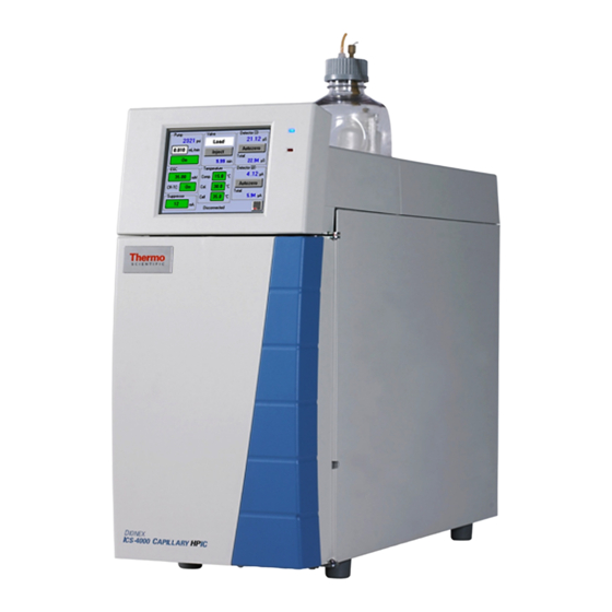
- Page 1 Thermo Scientific Dionex ICS-4000 Capillary HPIC System Installation Instructions 065469 Revision 02 September 2014...
- Page 2 © 2014 Thermo Fisher Scientific Inc. All rights reserved. Chromeleon is a registered trademark of Thermo Fisher Scientific Inc. in the United States. Microsoft and Windows are registered trademarks of Microsoft Corporation in the United States and other countries. PharMed is a registered trademark of Saint-Gobain Performance Plastics Corporation in the United States and possibly other countries.
- Page 3 Thermo Fisher Scientific or one of its authorized representatives. The cETLus or cTUVus and CE marks on the model/data labels on the Dionex ICS-4000 module indicate that the module is in compliance with the following standards.
- Page 4 Notice on Lifting and Handling of Thermo Scientific Instruments For your safety, and in compliance with international regulations, the physical handling of this Thermo Fisher Scientific instrument requires a team effort to lift and/or move the instrument. This instrument is too heavy and/or bulky for one person alone to handle safely.
- Page 5 WEEE Compliance This product is required to comply with the European Union’s Waste Electrical & Electronic Equipment (WEEE) Directive 2002/96/EC. It is marked with the following symbol: Thermo Fisher Scientific has contracted with one or more recycling or disposal companies in each European Union (EU) Member State, and these companies should dispose of or recycle this product.
- Page 6 Conformité DEEE Ce produit doit être conforme à la directive européenne (2002/96/EC) des Déchets d'Equipements Electriques et Electroniques (DEEE). Il est marqué par le symbole suivant: Thermo Fisher Scientific s'est associé avec une ou plusieurs compagnies de recyclage dans chaque état membre de l’union européenne et ce produit devrait être collecté...
- Page 7 CAUTION Symbol CAUTION VORSICHT ATTENTION PRECAUCION AVVERTENZA Electric Shock: This instrument uses Elektroschock: In diesem Gerät werden Choc électrique: L’instrument utilise des Descarga eléctrica: Este instrumento Shock da folgorazione. L’apparecchio è high voltages that can cause personal Hochspannungen verwendet, die tensions capables d’infliger des blessures utiliza altas tensiones, capaces de alimentato da corrente ad alta tensione...
- Page 8 CAUTION Symbol CAUTION Electric Shock: This instrument uses high voltages that can cause personal injury. Before servicing, shut down the instrument and disconnect the instrument from line power. Keep the top cover on while operating the instrument. Do not remove protective covers from PCBs. Chemical: This instrument might contain hazardous chemicals.
-
Page 9: Table Of Contents
Unpacking the Dionex ICS-4000 ........ - Page 10 Appendix D Setting Up the Piston Seal Wash System ....... . .77 Dionex ICS-4000 Installation Instructions...
-
Page 11: Preface
Preface This manual provides instructions for the initial installation of the Thermo Scientific™ Dionex™ ICS-4000 Capillary HPIC™ System. Follow the installation instructions in this manual, in the order presented. These instructions have been carefully developed to ensure that installation of the Dionex ICS-4000 Capillary HPIC System is successful. -
Page 12: Safety And Special Notices
Table Table 1. ASTM filtered, Type I deionized water specifications for ion chromatography Contaminant Specification Ions–Resistivity >18.0 (megohm-cm) Organics–TOC <10 ppb Iron/Transition Metals* <1 ppb Pyrogens <0.03 (Eu/mL) Particulates > 0.2 μm <1 (units/mL) Dionex ICS-4000 Installation Instructions Thermo Scientific... -
Page 13: Fitting And Tube Connection Guidelines
* Iron/transition metal content not specified for ASTM Type I water Fitting and Tube Connection Guidelines Follow these guidelines when connecting tube fittings in the Dionex ICS-4000: • Use high-pressure 10-32 fitting bolts (P/N 074449) and high-pressure 10-32 double-cone ferrules (P/N 074373) for all connections. Fitting bolts and ferrules are included in the Dionex ICS-4000 Ship Kit (P/N 075161). -
Page 14: Tightening Ferrule Fittings
Make sure the cut is at a right angle to the length of the tubing and there are no nicks or burrs on the end. A tubing cutter (P/N 049584) is included in the Dionex ICS-4000 Ship Kit (P/N 075161). Refer to the instructions provided with the cutter. -
Page 15: Using The Touch Screen
• To change a numerical value (for example, the column temperature), touch the box showing the current value (for example, ). A keypad opens (see Figure Touch the numbers on the keypad and then touch ENTER Thermo Scientific Dionex ICS-4000 Installation Instructions... -
Page 16: Using The Touch Screen With Chromeleon
Home screen. In this mode, most of the controls on the touch screens are disabled. This prevents touch screen commands from conflicting with Chromeleon commands. In general, when the Dionex ICS-4000 is connected to Chromeleon, you can: • View all operational status information (pressure, flow rate, conductivity readings, etc.) •... -
Page 17: Configurations
Preface Configurations Configurations The table below describes some of the common Dionex ICS-4000 system configurations. System configuration Typical components included Dionex ICS-4000 • Thermo Scientific Dionex ICS-4000 Conductivity Detector with conductivity (CD) detection • Thermo Scientific Dionex CES™ 300 Capillary Electrolytic Suppressor (ACES™... - Page 18 Preface Configurations xviii Dionex ICS-4000 Installation Instructions Thermo Scientific...
-
Page 19: Unpacking Instructions
MISE EN GARDE Au moins deux personnes peuvent soulever l'Dionex ICS-4000, qui pèse plus de 23 kg (50 lb). Ne soulevez l'Dionex ICS-4000 que par chaque côté du fond de l'armoire. Son soulèvement par la porte du panneau avant endommagera les charnières de la porte. - Page 20 Unpacking Instructions Unpacking the Dionex ICS-4000 Note Check the shipping container for any external signs of damage. If the container shows signs of damage, contact Thermo Fisher Scientific immediately. 1. Follow the instructions printed on the shipping container to turn the...
-
Page 21: Unpacking The Autosampler
1. If you are installing an autosampler, follow the instructions in the autosampler manual to unpack the autosampler now. 2. Place the autosampler to the left of the Dionex ICS-4000 on the workbench. Unpacking the Computer 1. Remove the computer and all documentation from the computer box and place them on a workbench. -
Page 22: Unpacking The Consumable Devices
(KOH), ou un acide corrosif (MSA). Porter des lunettes et des gants protectives en manipulant la cartouche. VORSICHT Die EGC-Kartusche enthält eine korrosive Base (KOH) oder eine korrosive Säure (MSA). Tragen Sie daher beim Umgang mit der Kartusche eine Schutzbrille und Handschuhe. Dionex ICS-4000 Installation Instructions Thermo Scientific... -
Page 23: System Setup
To connect the power cord 1. Verify that the power switch on the rear panel of the Dionex ICS-4000 is turned off. The power switch may be turned on accidentally when the module is unpacked. 2. Connect the power cord (IEC 320 C13) (ordered separately) from the main power receptacle on the rear panel to a grounded power source. - Page 24 System Setup Connecting the Dionex ICS-4000 Power Cord WARNING SHOCK HAZARD—To avoid electrical shock, use a grounded receptacle. Do not operate the IC system or connect it to AC power mains without an earthed ground connection. CAUTION The power supply cord is used as the main disconnect device. Make sure the socket-outlet is located near the IC system and is easily accessible.
-
Page 25: Plugging In The Egc And Cr-Tc
6. Hold the EGC with the ports on the bottom and slide it into the EGC holder on the left side of the tray. The pre-assembled tubing chain (see Figure 9) may prevent the EGC from sliding all the way into the holder. Do not connect the tubing yet. Thermo Scientific Dionex ICS-4000 Installation Instructions... - Page 26 Push the cable connector firmly onto the connector and twist the locking ring fingertight to secure it. Figure 11. Front tray with EGC and CR-TC connected EGC cable and connector 4-pin EGC cable connector CR-TC cable CR-TC and connector 3-pin CR-TC cable connector Dionex ICS-4000 Installation Instructions Thermo Scientific...
-
Page 27: Installing Cartridges In The Dionex Ic Cube
(see Figure 12). The required cartridges depend on the detection type (see Table Figure 12. Dionex ICS-4000 with front door open Dionex IC Cube Table 2. Dionex IC Cube cartridge requirements Detection Type Required Cartridges Conductivity •... -
Page 28: Installing The Detector
IMPORTANT Install the saved regenerant port caps onto the CRD and CES bypass cartridge ports. Save the bypass cartridges. The bypass cartridges must be reinstalled if the Dionex ICS-4000 is used for an application that does not require a CRD or suppressor. Installing the Detector IMPORTANT Always turn off the Dionex ICS-4000 system power before installing or un-installing an ED, CD, or QD. - Page 29 1. If the system power is on, flip the power switch on the rear panel to turn off the power. 2. Locate the cover plate for the QD installation location on the right of the CD (see Figure 14). Thermo Scientific Dionex ICS-4000 Installation Instructions...
-
Page 30: Connecting An Autosampler
To connect the autosampler sample transfer line 1. Place the autosampler to the left of the Dionex ICS-4000 on the lab bench. 2. Route the sample transfer line from the autosampler through the side slot on the lower left side of the Dionex ICS-4000 to the Dionex IC Cube. - Page 31 System Setup Connecting an Autosampler 4. For a Thermo Scientific Dionex AS-AP Autosampler: a. Route the line to the Dionex AS-AP waste port and insert the line into one of the round openings in the waste port (see Figure 17).
-
Page 32: Connecting To The Computer
15 for software installation information. • Do not turn on the power to the Dionex ICS-4000 or other USB device until after you connect the USB cable. You can connect the system directly to a USB port on the Chromeleon computer or to a USB 2.0 external hub that is connected to the computer. -
Page 33: Setting Up The Chromatography Software
Setting Up the Chromatography Software Note You can set up the software now or wait until later in the installation procedure. The hardware installation procedure can be completed using the Dionex ICS-4000 front panel touch screen only. Software setup consists of installing Chromeleon software and the software license on the computer (if they are not already installed) and starting the Chromeleon 7 Instrument Controller Service or Chromeleon 6.8 Server Configuration Program. -
Page 34: Starting The Chromeleon 7 Instrument Controller Service Or Chromeleon 6.8 Server
Chromeleon recognizes the installed devices at power-up and includes them in the configuration. 2. Turn on the power switch on the rear panel of the Dionex ICS-4000. 3. If you are installing an autosampler, turn on the autosampler power now. -
Page 35: Configuring The Dionex Ics-4000 In Chromeleon
The Chromeleon USB Auto Configuration Wizard appears automatically when a USB device that is not assigned to a Chromeleon 7 instrument or Chromeleon 6.8 timebase is powered up. You can use the wizard to create a new instrument or timebase for your Dionex ICS-4000. If you prefer, click... -
Page 36: Connecting The Drain, Waste, And Vent Lines
CD, direct the EG degas vent line to a waste container. To connect the leak and condensation drain line 1. Locate the corrugated drain line (P/N 055075) in the Dionex ICS-4000 Ship Kit (P/N 075161). Dionex ICS-4000 Installation Instructions... - Page 37 To connect the waste lines 1. Locate the gas separator waste tube assembly (P/N 045460) in the Dionex ICS-4000 Ship Kit. 2. Untape the coiled waste lines from the rear panel and connect the ends to the unions on the 3 mm (1/8 in) ID white PTFE tubing extending out of the gas separator waste tube assembly.
-
Page 38: Degassing The Water
Degas the deionized water that will be used to fill the eluent reservoir. See “Deionized Water Requirements for IC” page xii. Note If you have not set up the computer and software, you can do this while waiting for water degassing to finish. Dionex ICS-4000 Installation Instructions Thermo Scientific... -
Page 39: Setting Up The Reservoir
• Condition and hydrate consumable devices (EGC, CR-TC, CES, CRD) • Generate eluent 2. Place the reservoir in the reservoir organizer on top of the Dionex ICS-4000. 3. If an end-line filter is not installed, locate the filter (P/N 045987) in the Dionex ICS-4000 Ship Kit (P/N 075161) and install it on the end of the reservoir’s eluent line. - Page 40 Deionized water or eluent from the eluent reservoir passes through the degasser before it enters the pump. Optional: If a Dionex AS-AP will be used with the Dionex ICS-4000, a separate vacuum degasser can be installed for degassing the flush fluid used with the autosampler. A Dionex...
-
Page 41: Priming The Pump
For instructions, see “Pressurizing Eluent Reservoirs” page Setting Up the Pump Seal Wash System If the Dionex ICS-4000 will be equipped with a pump seal wash system, install the system now. For instructions, see “Setting Up the Piston Seal Wash System” page... -
Page 42: Checking The Conductivity Of The Water
3. Verify that the conductivity is 1 μS or below. 4. If the conductivity is greater than 1 μS, refill the syringe with fresh water (or use water from a different source) and then recheck the conductivity. Dionex ICS-4000 Installation Instructions Thermo Scientific... -
Page 43: System Plumbing
Filling and Flushing the ED Liquid Path Flushing and Conditioning the Electrolytic Devices Flushing and Installing the Columns Completing the Plumbing for Conductivity Detection Completing the Plumbing for Electrochemical Detection Equilibrating the System Installing a Dionex QDC 300 (Capillary) Thermo Scientific Dionex ICS-4000 Installation Instructions... -
Page 44: Pre-Assembled Tubing
18 cm (7 in) (0.062 in) ID clear ETFE, 2 m (7 ft) (P/N 078432) TO CR-TC EL OUT / EG DEGAS IN 0.062 mm (0.0025 in) ID blue PEEK, 33.65 cm (13.25 in) Dionex ICS-4000 Installation Instructions Thermo Scientific... -
Page 45: System Plumbing Checklists
The trap column, as well as a tubing assembly (P/N 078497) for installing the trap column, are provided in the Dionex ICS-4000 Ship Kit. The trap column installs between the pressure transducer and the EGC inlet. -
Page 46: Filling And Flushing The Cd Regenerant Path
CRD regenerant pathways, including the connecting path in the interior of the Dionex IC Cube. To fill and flush the CD regenerant path 1. If you have not already done so, install the CES cartridge and CRD cartridge (if used) in the Dionex IC Cube. Dionex ICS-4000 Installation Instructions Thermo Scientific... - Page 47 REGEN IN note the difference in the pump pressure. c. If the difference is less than 0.7 MPa (100 psi), the low-pressure flow path is ready and you can proceed to the next step. Thermo Scientific Dionex ICS-4000 Installation Instructions...
-
Page 48: Checking The Background Conductivity
Completing the IQ and System Function Test Complete the appropriate Installation Qualification (IQ) checklist and the system function test to confirm that the Dionex ICS-4000 is correctly installed and the basic system components (injection valve, pump, and detector) are functioning correctly. -
Page 49: Filling And Flushing The Ed Liquid Path
4. Connect the EG degas line to the injection valve port. ELUENT OUT ELUENT IN 5. On the Pump screen, under Prime/Flush, select and touch . Run the 0.1 mL/min Flush pump for 30 min. Thermo Scientific Dionex ICS-4000 Installation Instructions... -
Page 50: Flushing And Conditioning The Electrolytic Devices
IMPORTANT To ensure proper ventilation, always install the luer fitting on the top of the EGC before operation. If you need to remove the EGC from the system, reinstall the vent fitting to prevent leaks. Dionex ICS-4000 Installation Instructions Thermo Scientific... - Page 51 (P/N 072204) From pump pulse damper To waste 1. Connect the backpressure tubing (P/N 074582) between the line and the EGC EGC OUT port. 2. Set the pump flow rate to and touch 0.03 mL/min Thermo Scientific Dionex ICS-4000 Installation Instructions...
- Page 52 3. Verify that the EGC current is off and the CR-TC voltage is off. 4. Set the pump flow rate to and touch . Flush the CR-TC for 10 minutes. 0.03 mL/min Verify that liquid is flowing steadily from the CR-TC line. REGEN OUT Dionex ICS-4000 Installation Instructions Thermo Scientific...
- Page 53 ELUENT IN DEGAS ELUENT IN ELUENT OUT ELUENT OUT ELUENT OUT ELUENT IN Through VENT REGEN IN REGEN IN ELUENT OUT tubing chase SAMPLE IN 5000 psi to rear panel SAMPLE OUT To waste Thermo Scientific Dionex ICS-4000 Installation Instructions...
-
Page 54: Flushing And Installing The Columns
Thermo Scientific Reference Library DVD (P/N 053891). To flush the columns 1. Locate the Dionex IC Cube Tubing Kit (P/N 072186) in the Dionex ICS-4000 Ship Kit (P/N 075161). The kit contains precision-cut tubing and the fittings required for installing various column configurations. - Page 55 (see Figure 36). To indicate the placement of columns in the tray, labels and column guides are molded into the tray. Figure 36. Empty column tray Column guide Label Tubing clip Fitting clip Thermo Scientific Dionex ICS-4000 Installation Instructions...
- Page 56 Figure 38. 250 mm analytical column and 50 mm guard column installed in column tray 65 mm (2.56 in) precision-cut tubing Analytical column inlet Analytical column outlet Guard column outlet 125 mm (4.92 in) Guard column precision-cut tubing inlet (inlet line) Dionex ICS-4000 Installation Instructions Thermo Scientific...
- Page 57 Figure 40. 150 mm analytical column and 35 mm guard column installed in column tray 65 mm (2.56 in) precision-cut Analytical tubing column inlet Analytical column outlet Guard column outlet 125 mm (4.92 in) Guard column precision-cut tubing inlet (inlet line) Thermo Scientific Dionex ICS-4000 Installation Instructions...
- Page 58 7. Slide the column tray into the Dionex IC Cube column heater and tighten the two thumbscrews. 8. Reconnect the column inlet tubing to the injection valve. Dionex ICS-4000 Installation Instructions Thermo Scientific...
-
Page 59: Completing The Plumbing For Conductivity Detection
CRD line to the CD port. ELUENT OUT 3. If a CRD is not installed, connect the CES line to the CD port. ELUENT OUT The flow path is ready for equilibration and operation. Thermo Scientific Dionex ICS-4000 Installation Instructions... -
Page 60: Completing The Plumbing For Electrochemical Detection
SAMPLE IN 5000 psi panel SAMPLE OUT From To waste autosampler To complete the plumbing for an ED 1. Connect the cell inlet line (P/N 082618) to the column port. ELUENT OUT Dionex ICS-4000 Installation Instructions Thermo Scientific... -
Page 61: Equilibrating The System
15 °C. Set the temperature of the column heater as required for the installed column type. 4. Verify that the setting (flow rate, eluent concentration, temperature, and so on) for each device installed in your system is correct for your application. Thermo Scientific Dionex ICS-4000 Installation Instructions... - Page 62 IC system on at all times, allowing it to remain equilibrated and always ready to run the next sample. This completes the Dionex ICS-4000 installation procedure for CD and ED systems. If you are installing a charge detector, go on to “Installing a Dionex QDC 300 (Capillary)”...
-
Page 63: Installing A Dionex Qdc 300 (Capillary)
Front view Back view Electrical ELUENT IN port Ball stud connector Figure 45. CD and QD before installation of the QDC Electrical receptacle for the QDC Opening for the ball stud on the QDC Thermo Scientific Dionex ICS-4000 Installation Instructions... - Page 64 8. Remove the waste line from the QDC port. REGEN OUT To complete the plumbing For reference, Figure 47 shows the Dionex IC Cube and detector plumbing after all connections for conductivity detection with charge detection are completed. Dionex ICS-4000 Installation Instructions Thermo Scientific...
- Page 65 REGEN OUT 2. Turn on the CES current. The QDC is now ready for use. This completes the Dionex ICS-4000 installation procedure for a CD with QD. For operating instructions, refer to Dionex ICS-4000 Capillary HPIC System Operator’s Manual (Document No. 065468). The manual is provided on the Thermo Scientific Reference Library DVD (P/N 053891).
- Page 66 System Plumbing Installing a Dionex QDC 300 (Capillary) Dionex ICS-4000 Installation Instructions Thermo Scientific...
-
Page 67: Installing The Ed Amperometry Cell
Figure 48. ED cell components Cell outlet Yoke knob (with fitting plug) and block Cell inlet Spacer block Titanium cell inlet tubing Cell body (remove for use with the Dionex ICS-4000) Cell cable Thermo Scientific Dionex ICS-4000 Installation Instructions... -
Page 68: Chapter A Installing The Ed Amperometry Cell
Figure 49. ED cell disassembled Cell body Spacer block 5. Remove the protective film from the alignment pins on the cell body (see Figure 50). Figure 50. ED cell body with protective film Protective film (remove) Dionex ICS-4000 Installation Instructions Thermo Scientific... -
Page 69: Installing The Working Electrode
For installation instructions for disposable working electrodes, refer to the installation guide shipped with the electrodes (see below) or to the Product Manual for Disposable Electrodes (Document No. 065040), which is included on the Thermo Scientific Reference Library DVD (P/N 053891). -
Page 70: Installing A Conventional Working Electrode
When correctly installed, one end of the gasket extends beyond the cell body, to facilitate gasket installation and removal. Figure 52. ED cell gasket for conventional working electrode Cell gasket for conventional working electrodes Alignment pins Dionex ICS-4000 Installation Instructions Thermo Scientific... - Page 71 5. Install the reference electrode: • If you are installing a pH-Ag/AgCl reference electrode, go on to page • If you are installing a PdH reference electrode, go on to page Thermo Scientific Dionex ICS-4000 Installation Instructions...
-
Page 72: Installing The Ph-Ag/Agcl Reference Electrode
KCl solution when the cell is not in use. This prevents the pH-Ag/AgCl reference electrode membrane from drying out and damaging the electrode. 3. Rinse the pH-Ag/AgCl reference electrode thoroughly in ASTM Type I (18 megohm-cm) filtered and deionized water to remove any precipitated salt. Dionex ICS-4000 Installation Instructions Thermo Scientific... - Page 73 Attach the cup holder below the detector (see Figure 56). 4. Connect the cell electrical cable and the pH-Ag/AgCl reference electrode electrical cable to the ED. Place the electrode in the cup; do not install the electrode in the cell yet. Thermo Scientific Dionex ICS-4000 Installation Instructions...
- Page 74 To install the pH-Ag/AgCl reference electrode in the cell 1. To avoid any hydraulic pressure buildup when inserting the reference electrode into the cell, make sure that fitting plugs are not installed on the cell inlet and outlet fittings. Dionex ICS-4000 Installation Instructions Thermo Scientific...
- Page 75 Figure 59. Reference electrode well with gasket for capillary IC installed Reference electrode well inlet Reference electrode well outlet 4. Verify that the reference electrode O-ring has been removed and the reference electrode gasket is correctly installed in the bottom of the well. Thermo Scientific Dionex ICS-4000 Installation Instructions...
-
Page 76: Installing The Pdh Reference Electrode
2. Using tweezers, grasp the PdH reference electrode gasket (P/N 072214) on its edge (see Figure 61). To avoid deforming the gasket cutout, do not place the tweezer tips on the cutout. Figure 61. PdH reference electrode gasket PdH reference electrode gasket Cutout Dionex ICS-4000 Installation Instructions Thermo Scientific... - Page 77 6. Screw the nut on the PdH reference electrode into the reference electrode well and tighten it fingertight. After tightening with your fingers, use a wrench to tighten the nut an additional 20 to 30 degrees (see Figure 64). Thermo Scientific Dionex ICS-4000 Installation Instructions...
- Page 78 7. Orient the cell assembly with the yoke knob on the left and then push the cell onto its mounting location on the ED. 8. To continue the system installation, go to “Filling and Flushing the ED Liquid Path” page Dionex ICS-4000 Installation Instructions Thermo Scientific...
-
Page 79: Appendix B Pressurizing Eluent Reservoirs
Pressurizable reservoirs allow eluents to be stored under a specific atmosphere. All eluent reservoirs available for use with the Dionex ICS-4000 can be pressurized. To pressurize the eluent reservoirs, a Dionex ICS-4000 Regulator Kit (P/N 078520) is required. The kit includes the following parts: •... - Page 80 Pressurizing Eluent Reservoirs To mount the assembly on the Dionex ICS-4000 rear panel 1. Position the mounting bracket over the three screw holes on the upper left side of the rear panel. 2. Use the screws and 3 mm Allen wrench provided in the Regulator Kit to attach the...
- Page 81 Figure 68. Gas connections to the regulator and reservoir Gas shutoff valve for reservoir 4. Push the luer/valve fitting onto the luer fitting on the reservoir cap. This is the gas shutoff valve for the reservoir. Thermo Scientific Dionex ICS-4000 Installation Instructions...
- Page 82 VORSICHT Setzen Sie den Eluentbehälter auf keinen Fall einem Druck über 0,07 MPa aus. 5. If the liquid line from the pump is connected, you may open the gas shutoff valve on the reservoir cap. Dionex ICS-4000 Installation Instructions Thermo Scientific...
-
Page 83: Appendix C Installing The Low-Pressure Valves And Peristaltic Pump
Installing the Low-Pressure Valves and Peristaltic Pump This appendix describes how to install the following options in the Dionex ICS-4000: • Low-pressure valves (two-way valves, P/N 079848; three-way valves, P/N 061971). Two-way valves provide on/off control of liquid flow in one direction. Three-way valves provide control of liquid flow in two directions. - Page 84 0 is open (N.O.) and N.C. = normally closed port 1 is closed (N.C.). Conversely, when the valve is on, port 1 is open N.O. = normally open and port 0 is closed. COM = common flow Dionex ICS-4000 Installation Instructions Thermo Scientific...
- Page 85 1. Configure the valve in Chromeleon: a. Open the Chromeleon 7 Instrument Configuration Manager or Chromeleon 6.8 Server Configuration program. b. Under the instrument or timebase, right-click the Dionex ICS-4000 System and click Properties c. Click the tab and select the check box for the installed valve.
- Page 86 Figure 73. Low-pressure valve control on the ICS-4000 ePanel in Chromeleon 7 To control a low-pressure valve from the touch screen Touch on the Menu screen to go to the Valve screen (see Figure 75). Valve Figure 74. Valve screen Dionex ICS-4000 Installation Instructions Thermo Scientific...
-
Page 87: Installing And Operating A Peristaltic Pump
To install a peristaltic pump 1. The peristaltic pump is shipped with a mounting stand (see Figure 75) that is designed to sit on the workbench next to the Dionex ICS-4000. Figure 75. Peristaltic pump and mounting stand Peristaltic pump Mounting stand... - Page 88 Note The upper keyhole openings can be used for a second peristaltic pump or an auxiliary high-pressure valve. Figure 76. Peristaltic pump mounted on stand (for left-side installation) 3. To attach the mounting stand to the Dionex ICS-4000 as shown in Figure 77, raise the front of the system and slide the base of the mounting stand under the system.
- Page 89 PharMed tubing d. Slide the cap over the retainer sleeve and tighten the cap onto the body. e. Follow the same procedure to install a peristaltic tubing adapter on the other end of the tubing. Thermo Scientific Dionex ICS-4000 Installation Instructions...
- Page 90 (see Figure 82). Close the tubing clamp by pushing it to the left until the tabs lock into place. Figure 82. Peristaltic tubing installation completed Push here to close the clamp Dionex ICS-4000 Installation Instructions Thermo Scientific...
- Page 91 1. Configure the pump in Chromeleon: a. Open the Chromeleon 7 Instrument Configuration Manager or Chromeleon 6.8 Server Configuration program. b. Under the instrument or timebase, right-click the Dionex ICS-4000 System and click Properties Thermo Scientific Dionex ICS-4000 Installation Instructions...
- Page 92 • Select commands in the Chromeleon 7 Command window (see Figure 85) or the Chromeleon 6.8 Commands dialog box. Figure 85. Chromeleon 7 Command window For a description of the commands, see “Control Commands for the PWM Drive” page Dionex ICS-4000 Installation Instructions Thermo Scientific...
- Page 93 59 minutes off ). To specify the interval, enter times in the On and Off boxes under Interval Duration. • turns off the pump. Speed 0% is off and 100% is full speed. The flow rate at 100% is about 7 mL/min. Thermo Scientific Dionex ICS-4000 Installation Instructions...
- Page 94 Installing the Low-Pressure Valves and Peristaltic Pump Installing and Operating a Peristaltic Pump Dionex ICS-4000 Installation Instructions Thermo Scientific...
-
Page 95: Appendix D Setting Up The Piston Seal Wash System
Thermo Fisher Scientific offers a Seal Wash Kit (P/N 078434) for connecting a piston seal washing system to the Dionex ICS-4000 pump. When seal washing is installed, the back of the main piston seal is rinsed with wash solution (usually deionized water); this prolongs seal lifetime by preventing eluent crystallization on the piston surfaces. - Page 96 6. Slide the seal wash pump module into the opening and secure it with the screws that were removed with the cover plate. 7. Reinstall the waste line fitting and waste line onto the pressure transducer and reconnect the quick-disconnect fitting on the waste line. Dionex ICS-4000 Installation Instructions Thermo Scientific...
- Page 97 OUTPUT module (see Figure 91). Figure 91. Seal wash pump module tubing connections Tubing clips INPUT 81 cm (32 in) Secondary tubing pump head OUTPUT 30 cm (12 in) tubing Thermo Scientific Dionex ICS-4000 Installation Instructions...
- Page 98 Tubing clips 8. Connect the 1/4-28 fitting to the fitting on the seal wash reservoir cap (see Figure 93). Figure 93. Seal wash reservoir in reservoir organizer Tubing chase 1/4-28 fitting on input tubing Dionex ICS-4000 Installation Instructions Thermo Scientific...
- Page 99 3. On the touch screen Menu screen, select . Under Seal Wash Pump, touch the Accessory box and touch . Run the pump until the input and output lines are filled and Mode liquid enters the waste tubing. Touch Thermo Scientific Dionex ICS-4000 Installation Instructions...
- Page 100 To select seal wash operating settings from Chromeleon 1. Open the Chromeleon 7 ePanel Set or Chromeleon 6.8 panel tabset. 2. Press the key. 3. Under Pump_TC, select and enter the preferred values for the seal wash Seal_Wash properties. Dionex ICS-4000 Installation Instructions Thermo Scientific...
Need help?
Do you have a question about the Dionex ICS-4000 and is the answer not in the manual?
Questions and answers