Table of Contents
Advertisement
Quick Links
Directions for Use
FU
RATE (mL/h)
CHANNEL
SELECT
PAUSE
CHANNEL
OFF
RESTART
Alaris
SILENCE
SYSTEM
OPTIONS
ON
1
2
3
4
5
6
7
8
9
ENTER
.
0
CLEAR
CANCEL
System
®
Supports Guardrails
FU
RATE (mL/h)
PULSE (BPM)
CHANNEL
SELECT
PAUSE
CHANNEL
OFF
RESTART
Suite MX (v8)
®
August 2005
ONI
% SpO 2
CHANNEL
SELECT
MONITOR
CHANNEL
OFF
Alaris
Products
®
Advertisement
Chapters
Table of Contents
Troubleshooting

Related Manuals for Cardinal Health Alaris 8000 Series


Summary of Contents for Cardinal Health Alaris 8000 Series
- Page 1 Directions for Use Alaris System ® Supports Guardrails Suite MX (v8) ® August 2005 % SpO 2 RATE (mL/h) RATE (mL/h) PULSE (BPM) CHANNEL SELECT CHANNEL SELECT CHANNEL PAUSE SELECT SILENCE PAUSE SYSTEM MONITOR OPTIONS CHANNEL CHANNEL CHANNEL RESTART RESTART ENTER CLEAR CANCEL...
-
Page 2: Table Of Contents
..................Order Numbers: Electronic Copy: 10012555 Printed Copy: 10012398 ©2005 Cardinal Health, Inc. or one of its subsidiaries. All rights reserved. Alaris System Directions for Use ®... -
Page 3: General Contact Information
General Contact Information Cardinal Health http://www.cardinal.com/alaris Alaris Products ® 10221 Wateridge Circle San Diego, California 92121 Customer Advocacy - North America Clinical and technical feedback. Phone: 800.854.7128, Ext. 7812 E-Mail: CustomerFeedback@cardinal.com Technical Support - North America Maintenance and service information support; troubleshooting. -
Page 4: Introduction
Introduction The Alaris PC Point-of-Care Unit ("PC Unit") Section of this ® WARNING Directions for Use (" ") provides procedures and Read all instructions before using information applicable to the Alaris System and the PC Unit. ® the Alaris System. ®... - Page 5 Cardinal Health, Inc., was formerly known as Medical Systems, Inc. Alaris product labeling will ALARIS ® transition to the Cardinal Health name over time. During this transition, product labeling may reflect the Medical ALARIS Systems name and/or Cardinal Health name.
- Page 6 Installation Instruments are tested and calibrated before they are packaged for shipment. To ensure proper operation after shipment, it is recommended that an incoming inspection be performed before placing the instrument in use. Prior to placing the Alaris System in use: ®...
- Page 7 Alaris PC Point-of-Care Unit ® 8000 Series SILENCE SYSTEM OPTIONS ENTER CLEAR CANCEL Alaris System DFU, Section ®...
- Page 9 Table of Contents GETTING STARTED INTRODUCTION ....................GENERAL SETUP AND OPERATION ATTACHING AND DETACHING MODULES .
- Page 10 TROUBLESHOOTING AND MAINTENANCE (Continued) BATTERY CARE AND MAINTENANCE 1-40 ................Battery Type and Charging 1-40 .
-
Page 11: Introduction
Getting Started Introduction This Section of the Directions for Use ( ) provides Alaris ® WARNING PC Point-of-Care Unit ("PC Unit") and Alaris System ® Read all instructions, including instructions and information. It is used in conjunction with the those for the attached module(s) following: and applicable accessories, before using the Alaris... - Page 12 T H I S PA G E I N T E N T I O N A L LY L E F T B L A N K Alaris System Directions for Use Getting Started ® PC Unit Section...
-
Page 13: Attaching And Detaching Modules
General Setup and Operation Attaching and Detaching Module(s) Modules can be attached to either side of the PC Unit or to either side of another module. The process to attach or detach is the same for either side, whether attaching/ detaching to/from a PC Unit or another module. -
Page 14: Detaching Modules(S)
Attaching and Detaching Modules (Continued) Detaching Module(s) Ensure module(s) is powered off before detaching. Push module release latch and then rotate module(s) up and away from PC Unit or attached module (opposite to motion shown above) to disengage connectors. • Alaris System reidentifies and shows appropriate ®... -
Page 15: Start-Up
Start-Up Powering On System Connect PC Unit to an external power source. Press SYSTEM ON System self test begins: • Diagnostics test causes all display segments and Status Indicator lights of attached module(s) to illuminate briefly. • Power Indicator illuminates. •... -
Page 16: Responding To Maintenance Reminder
Start-Up (Continued) Responding to Maintenance Reminder If the Preventive Maintenance ( ) Reminder option is MAINTENANCE REMINDER enabled and the PC Unit or an attached module is due for Module(s) due for routine preventive maintenance: preventive maintenance, a MAINTENANCE REMINDER Module A: YYYY-MM-DD message appears at power up. -
Page 17: Selecting New Patient And Profile Options
CONFIRM Darker ©2001-2005 Cardinal Health, inc. or one of its subsidiaries. All rights reserved. Guardrails® is a registered trademark of Cardinal Health, inc. or one of its subsidiaries. >Adjust Display to Desired Contrast CONFIRM Selecting New Patient and Profile Options The following procedures assume the Profiles feature is enabled. - Page 18 Start-Up (Continued) Selecting New Patient and Profile Options (Continued) To select a profile, press corresponding left soft key. Midtown Hospital 1 of 2 Profiles Adult ICU To confirm profile selection, press soft key. CONFIRM Adult General Care • Main screen appears. Neonatal Peds ICU Neonatal ICU...
-
Page 19: Adjusting Audio Volume
Start-Up (Continued) Selecting New Patient and Profile Options (Continued) Patient ID Entry Feature (Continued) NOTES: An alphanumeric identifier, of up to characters, can be entered. Press the soft key next to a letter group to list letters in that group. Press the soft key next to an individual letter to enter that letter. -
Page 20: Locking/Unlocking Tamper Resist
Start-Up (Continued) Locking/Unlocking Tamper Resist Initiate operation of applicable module(s). Press and hold Tamper Resist Switch, on back of PC Midtown Hospital Adult ICU Unit, for seconds (reference "General Information", VTBI = 250.0 mL "Features and Displays", "Operating Features, Controls, Indicators"). -
Page 21: Power Off System
Power Off System Press and hold key until a beep is heard CHANNEL OFF (approximately seconds) and then release to initiate power down. • During power off sequence, Main Display flashes Powering Down. Powering Down • Once all attached modules are powered off, PC Unit automatically powers down. -
Page 22: Patient Id
System Options (Continued) Patient ID Entering Press key. OPTIONS Press Patient ID soft key. System Options 1 of 2 Display Contrast Patient ID Time of Day Power Down All Channels Anesthesia Mode >Select an Option or EXIT PAGE EXIT DOWN Scan or manually enter patient identifier: •... - Page 23 System Options (Continued) Patient ID (Continued) Modifying Press key. OPTIONS Press Patient ID soft key. To clear entire entry, press key. CLEAR SILENCE SYSTEM OPTIONS To back up a single character at a time, press CANCEL key. ENTER CLEAR CANCEL To enter modified patient identifier, use numeric data entry keys and/or alpha speed keys.
- Page 24 System Options (Continued) Patient ID (Continued) Modifying (Continued) To accept modified Patient ID, press Yes soft key. Patient ID Entry Patient ID • Main screen appears with new Patient ID. 123456789CD will be changed to 234567891EF Is this correct? To retain original (old) Patient ID, press No soft key. •...
- Page 25 System Options (Continued) Time of Day (Continued) If time is correct, press soft key. CONFIRM System Options Time of Day Current time: Change Time 09:00 To change time, press Change Time soft key. >CONFIRM Time-of-Day EXIT CONFIRM Enter current Time of Day. System Options Time of Day Current time:...
-
Page 26: Power Down All Channels
System Options (Continued) Power Down All Channels Press key. OPTIONS Press Power Down All Channels soft key. System Options 1 of 2 Display Contrast Patient ID Time of Day Power Down All Channels Anesthesia Mode >Select an Option or EXIT PAGE EXIT DOWN... - Page 27 System Options (Continued) Anesthesia Mode (Continued) • Bolus dose is automatically available for: Guardrails Drugs that have bolus dose limits defined ® ♦ generic drug calculation setup ♦ • Anesthesia Mode, alternating with other required prompts, displays in prompt bar of Main Display. •...
- Page 28 System Options (Continued) Anesthesia Mode (Continued) Disabling The Anesthesia Mode can be disabled, and normal operation resumed, using either of the following three methods: • System Options menu. • Disconnecting from power. • Connecting to power. From System Options Menu Press key.
-
Page 29: Battery Runtime
System Options (Continued) Anesthesia Mode (Continued) Disabling (Continued) Disconnecting from AC Power (Continued) Press soft key. CONFIRM Anesthesia mode was discontinued when AC power cord was disconnected. Press CONFIRM to continue normal operation. >Press CONFIRM CONFIRM Battery Runtime Press key. OPTIONS Press soft key. -
Page 30: System Configuration
System Options (Continued) System Configuration Press key. OPTIONS Press soft key. PAGE DOWN Press System Configuration soft key. System Options 2 of 2 Battery Runtime System Configuration Serial Numbers Software Versions >Select an Option or EXIT PAGE PAGE EXIT DOWN Press PC Unit soft key. -
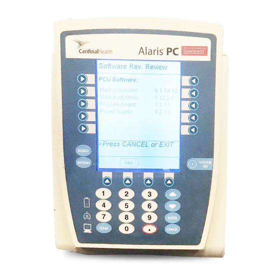
Page 31: Software Versions
System Options (Continued) System Configuration (Continued) System Config - PCU 2 of 3 Key click audio: Enabled Max Pt. BSA: Max Pt. weight: 500 kg Patient ID Entry: Disabled Pending IV Orders: Enabled >Press CANCEL or EXIT PAGE PAGE EXIT DOWN To return to main screen, press key or... - Page 32 System Options (Continued) Software Versions (Continued) To review software version information, press View soft Software Rev. Review key next to applicable module. PC Unit: View View Module A: Module B: View To return to main screen, press soft key. EXIT Module C: View Module D:...
-
Page 33: Warnings And Cautions
General Information Warnings and Cautions DANGER Explosion risk if used in the presence of flammable anesthetic agents or gasses. General WARNINGS • If an alarm condition occurs while the audio alarm is silenced, the only alarm indications will be visual displays and symbols related to the alarm condition. -
Page 34: Electromagnetic Compatibility
Warnings and Cautions (Continued) Electromagnetic Compatibility WARNINGS • Do not use the Alaris System near Magnetic Resonance ® Imaging ( • Use of any accessory, transducer or cable other than those specified may result in increased emissions or decreased Alaris System immunity. -
Page 35: Features And Displays
Features and Displays Features and Definitions Reference the product-specific Section of this that applies to the attached module(s) for features and definitions specific to that module. Data Set Created using Editor Software authoring tool and then transferred to PC Unit. A data set reflects facility’s best-practice guidelines for Drug administration and includes: Profile Drug Libraries, Clinical Advisories, instrument configurations, and Channel Label Libraries. - Page 36 Features and Displays (Continued) Features and Definitions (Continued) System Configuration Allow system settings to be customized. If Profiles feature is enabled, system settings defined for selected profile are automatically activated. Tamper Resist Provides a quick one-touch lockout of front panel keypad. 1-26 Alaris System Directions for Use...
-
Page 37: Operating Features, Controls, Indicators
Features and Displays (Continued) Operating Features, Controls, Indicators IUI Connector, Left IUI Connector, Right not visible Main Display Soft Keys: When pressed, allows selection of options or infusion parameters appearing on Main Display adjacent to soft key. Silence Key: When pressed System On Key: during an alarm, silences audio When... - Page 38 Features and Displays (Continued) Operating Features, Controls, Indicators (Continued) Connector, Right Connector, Left Power Cord Strap Use this bolt to reorient Pole Clamp 90 ° for attachment to a bed rail instead of a pole. Primary Audio Speaker Connector Plug over RJ45 Communication Data Port Tamper Resist Switch Option Upgrade Panel...
-
Page 39: Displays
Features and Displays (Continued) Displays The displays illustrated throughout this document are for illustration purposes only. The display content will vary, depending on configuration settings, hospital-defined data set uploaded using the Guardrails Suite MX, and many other ® variables. Main Display Title Bar Midtown Hospital Adult ICU... -
Page 40: System Configurable Settings
System Configurable Settings If the configuration settings need to be changed from the "Factory Default" settings, reference the applicable Technical Service Manual or contact Cardinal Health Technical Support, for technical, troubleshooting, and preventive maintenance information. With the Profiles feature enabled, the settings are configured independently for each profile. -
Page 41: Pca Module
Specifications and Symbols Specifications Battery Operation: Battery run time is a function of the number of modules attached and module activity. With a new, fully charged battery, the system will operate as follows before a " " message occurs: BATTERY DISCHARGED •... -
Page 42: Symbols
Specifications and Symbols (Continued) Specifications (Continued) NOTES: Reference the product-specific Section of this DFU for shock protection type and defibrillation-proof rating information. Power Cords: North America: To ensure correct polarity and grounding reliability, use power cords that incorporate a ) or ) plug only. - Page 43 Specifications and Symbols (Continued) Symbols (Continued) Fuse Replacement: Replace fuse only with same type and rating. IPX1 Protection against fluid ingress: Drip Proof Connector: Inter-Unit Interface connector used to establish power and communications between PC Unit and attached modules. Main Power: Connected to alternating current, 240 VAC Manufacturing Date: Number adjacent to symbol indicates month and year of manufacture.
- Page 44 T H I S PA G E I N T E N T I O N A L LY L E F T B L A N K 1-34 Alaris System Directions for Use General Information ® PC Unit Section...
-
Page 45: General
General The Alaris System Technical Service Manual is available from ® Cardinal Health. It includes routine service schedules, interconnect diagrams, component parts lists and descriptions, test procedures, and other technical information, to assist qualified service personnel in repair and maintenance of the instrument’s repairable components. -
Page 46: Maintenance
Alarms, Errors, Messages (Continued) Definitions (Continued) Error An audio and/or visual signal that a failure has been detected. Immediate action is required. Maintenance Reminder A visual message that, when enabled, appears at module startup when scheduled preventive maintenance is due/overdue for any part of Alaris System (PC Unit or attached module). -
Page 47: Alarms
Alarms, Errors, Messages (Continued) Alarms Alarm Meaning Response Battery Discharged Operation of all modules stopped Connect AC power cord to power due to insufficient battery charge. source; alarm will be silenced. Press key on affected RESTART module to continue operation of paused modules. - Page 48 Alarms, Errors, Messages (Continued) Errors (Continued) Error Meaning Response Defective Battery Defective battery. To power down system, press soft key; or to SYSTEM OFF continue temporary operation while an operational PC Unit can be located, press key. SILENCE Service by qualified personnel is required.
-
Page 49: Messages
Alarms, Errors, Messages (Continued) Messages Message Meaning Response Battery Run Time = X.X hours power cord is disconnected None. Connect power cord to from power source. Approximate power source as soon as possible. remaining battery run time under current power consumption rate is displayed. -
Page 50: Battery Care And Maintenance
Battery Care and Maintenance Battery Type and Charging The PC Unit is equipped with a volt, mAh nickel metal 4000 hydride battery. The battery is charging whenever the instrument is plugged into an receptacle. The life expectancy of the battery is dependent on the amount of use, the depth of discharge, and the state of the charge that is maintained. -
Page 51: Battery Cautions And Disposal
Battery Care and Maintenance (Continued) Battery Care (Continued) If the batteries are to be stored for more than year, they should be charged at least once per year to prevent leakage and deterioration in performance due to self-discharge. When the battery is first being put into use, or has been out of use for or more months, it will not have full capacity due to deactivation of reactants. - Page 53 Alaris Pump Module, 8100 Series ® Alaris Syringe Module, 8110 Series ® RATE (mL/h) CHANNEL SELECT CHANNEL SELECT PAUSE PAUSE CHANNEL CHANNEL RESTART RESTART Alaris System DFU, Section ®...
- Page 55 Table of Contents GETTING STARTED INTRODUCTION ....................PREPARING ADMINISTRATION SET (PUMP MODULE) .
- Page 56 GENERAL INFORMATION WARNINGS AND CAUTIONS 2-73 ..................General 2-73 .
- Page 57 Getting Started Introduction This Section of the Directions for Use ( ) provides Alaris ® WARNING Pump Module, Series ("Pump Module"), and Alaris 8100 ® Read all instructions, for both the Syringe Module, Series ("Syringe Module") instructions 8110 infusion modules and PC Unit, and information.
- Page 58 Introduction (Continued) Administration Sets / Syringes: Reference "General Information" for specific "Administration Set / Syringe Information". Alarms, Errors, Messages: Reference "Troubleshooting and Maintenance" for module-specific alarms, errors and messages. Contraindications: None known. Electromagnetic Environment: Reference "Appendix" Section of this ("Regulations and Standards", Compliance").
-
Page 59: Preparing Administration Set (Pump Module)
Preparing Administration Set ( Pump Module CHANNEL SELECT PAUSE CHANNEL RESTART For instructions on how to go from checking in a Pump WARNINGS Module to preparing it for an infusion setup, reference • To prevent a potential free-flow "General Setup and Operation". condition, ensure no extraneous object (for example, bedding, tubing, glove) is enclosed or... - Page 60 Preparing Administration Set ( ) (Continued) Pump Module CHANNEL SELECT PAUSE CHANNEL RESTART Loading (Continued) c. Press safety clamp fitment into recess below CAUTION mechanism. To reduce the potential for nuisance d. Using a finger tip, firmly push tubing toward back of alarms, ensure tubing is fully Air-in-Line ( ) Detector.
-
Page 61: Removing
Preparing Administration Set ( ) (Continued) Pump Module CHANNEL SELECT PAUSE CHANNEL RESTART Removing Close roller clamp. Open Pump Module door. • Set’s safety clamp fitment automatically closes to prevent accidental free-flow. White Slide Clamp (shown in closed position) Remove set, as follows: a. - Page 62 Preparing Administration Set ( ) (Continued) Pump Module CHANNEL SELECT PAUSE CHANNEL RESTART Priming (Continued) To prime tubing and clear air from injection sites and tubing fitments, slowly open roller clamp. When priming is complete, close roller clamp. Verify no fluid flow. RATE (mL/h) Preparing Syringe and Administration Set ( Syringe Module...
-
Page 63: Preparing Syringe And Administration Set (Syringe Module)
RATE (mL/h) Preparing Syringe and Administration Set ( Syringe Module (Continued) CHANNEL SELECT PAUSE CHANNEL RESTART Loading WARNINGS • Before loading the syringe, check it for damage or defects. • Ensure syringe barrel, flange, and plunger are installed and secured correctly. Failure to install syringe correctly can result in uncontrolled fluid flow to the patient, and may cause... - Page 64 RATE (mL/h) Preparing Syringe and Administration Set ( Syringe Module (Continued) CHANNEL SELECT PAUSE CHANNEL RESTART Loading (Continued) Raise drive head to its fully extended position. Drive Head Fully Extended a. Twist gripper control clockwise and hold in position. Gripper Control / Drive Head Release in Open b.
- Page 65 Preparing Syringe and Administration Set ( Syringe Module (Continued) RATE (mL/h) CHANNEL SELECT PAUSE CHANNEL RESTART Loading (Continued) Lower drive head and lock plunger in place with plunger Gripper Control in Closed Position grippers. a. Twist gripper control clockwise and hold in position. Drive Head Flush with Plunger Flange b.
- Page 66 RATE (mL/h) Preparing Syringe and Administration Set ( Syringe Module (Continued) CHANNEL SELECT PAUSE CHANNEL RESTART Loading (Continued) Syringe Module a. Orient pressure sensing disc, as follows: • fluid side up (patient side down) • cavity forward (membrane toward instrument) b.
-
Page 67: Priming
RATE (mL/h) Preparing Syringe and Administration Set ( Syringe Module (Continued) CHANNEL SELECT PAUSE CHANNEL RESTART Priming WARNING When priming: The Priming option can be enabled at the time the Alaris ® System is configured for use. The Priming selection ( •... - Page 68 RATE (mL/h) Preparing Syringe and Administration Set ( Syringe Module (Continued) CHANNEL SELECT PAUSE CHANNEL RESTART Priming (continued) Pressure Sensing Disc Installed (Continued) Press key. OPTIONS SILENCE SYSTEM OPTIONS ENTER CLEAR CANCEL Press Prime Set with Syringe soft key. Channel Options 1 of 2 Guardrails Drugs Guardrails IV Fluids Multidose...
- Page 69 RATE (mL/h) Preparing Syringe and Administration Set ( Syringe Module (Continued) CHANNEL SELECT PAUSE CHANNEL RESTART Priming (continued) Pressure Sensing Disc Installed (Continued) Prime, as follows: Patient Side a. Orient pressure sensing disc with patient side up. b. Depress and hold pressure sensing disc between fingers.
- Page 70 RATE (mL/h) Preparing Syringe and Administration Set ( Syringe Module (Continued) CHANNEL SELECT PAUSE CHANNEL RESTART Priming (continued) Pressure Sensing Disc Installed (Continued) Syringe Module Reinstall pressure sensing disc, as follows: a. Orient pressure sensing disc, as follows: • fluid side up (patient side down) •...
- Page 71 RATE (mL/h) Preparing Syringe and Administration Set ( Syringe Module (Continued) CHANNEL SELECT PAUSE CHANNEL RESTART Priming (continued) Pressure Sensing Disc Installed Press key. OPTIONS Press Prime Set with Syringe soft key. Channel Options 1 of 2 Guardrails Drugs Guardrails IV Fluids Multidose Pressure Limit - High Prime Set with Syringe...
- Page 72 T H I S PA G E I N T E N T I O N A L LY L E F T B L A N K 2-16 Alaris System Directions for Use Getting Started ® Pump and Syringe Modules Section...
-
Page 73: Programming
Programming References throughout this procedure to specific drugs and drug doses are for illustration purposes only. Refer to specific drug product labeling for information concerning appropriate administration techniques and dosages. Reference "General Information", "Features and Displays" and the PC Unit Section of this for information on the following: •... - Page 74 RATE (mL/h) Primary Infusion - With Guardrails Suite MX Protection (Continued) ® CHANNEL SELECT CHANNEL SELECT PAUSE PAUSE CHANNEL CHANNEL RESTART RESTART Press key. CHANNEL SELECT CHANNEL SELECT CHANNEL SELECT PAUSE PAUSE CHANNEL CHANNEL RESTART RESTART If a Syringe Module is being programmed, select WARNING syringe type and size, as follows;...
-
Page 75: Continuous Infusion
RATE (mL/h) Primary Infusion - With Guardrails Suite MX Protection (Continued) ® CHANNEL SELECT CHANNEL SELECT PAUSE PAUSE CHANNEL CHANNEL RESTART RESTART b. To accept, press soft key. CONFIRM Syringe Selection BD 30 mL Monoject 30 mL >Confirm Syringe Size CONFIRM SYRINGES Start applicable infusion, as described in following... - Page 76 RATE (mL/h) Primary Infusion - With Guardrails Suite MX Protection (Continued) ® CHANNEL SELECT CHANNEL SELECT PAUSE PAUSE CHANNEL CHANNEL RESTART RESTART Continuous Infusion (Continued) Press Guardrails Drugs soft key. Infusion Menu Guardrails Drugs Guardrails IV Fluids Basic infusion >Select an Option or EXIT EXIT RESTORE Press soft key next to desired drug.
- Page 77 RATE (mL/h) Primary Infusion - With Guardrails Suite MX Protection (Continued) ® CHANNEL SELECT CHANNEL SELECT PAUSE PAUSE CHANNEL CHANNEL RESTART RESTART Continuous Infusion (Continued) • If applicable, a weight-based, nonweight-based, or Guardrails Drugs ® Adult ICU -based option for delivery of this infusion may Heparin appear (as in illustrated example, which reflects use of Non-Weight based dosing...
- Page 78 RATE (mL/h) Primary Infusion - With Guardrails Suite MX Protection (Continued) ® CHANNEL SELECT CHANNEL SELECT PAUSE PAUSE CHANNEL CHANNEL RESTART RESTART Continuous Infusion (Continued) • If Yes was selected and facility has defined a Guardrails Drug Setup Alteplase Guardrails Clinical Advisory ("Clinical Advisory") for ®...
- Page 79 RATE (mL/h) Primary Infusion - With Guardrails Suite MX Protection (Continued) ® CHANNEL SELECT CHANNEL SELECT PAUSE PAUSE CHANNEL CHANNEL RESTART RESTART Continuous Infusion (Continued) An optional hospital-defined and editable starting value for continuous infusion dose may already be entered. To make a rate or dose entry, press applicable soft key, Guardrails Drug Setup A A A...
- Page 80 RATE (mL/h) Primary Infusion - With Guardrails Suite MX Protection (Continued) ® CHANNEL SELECT CHANNEL SELECT PAUSE PAUSE CHANNEL CHANNEL RESTART RESTART Continuous Infusion (Continued) Guardrails Drug Setup • If programmed continuous dose infusion is outside Alteplase Guardrails Soft Limit ("Soft Limit") for that care area, a ®...
- Page 81 RATE (mL/h) Primary Infusion - With Guardrails Suite MX Protection (Continued) ® CHANNEL SELECT CHANNEL SELECT PAUSE PAUSE CHANNEL CHANNEL RESTART RESTART Continuous Infusion (Continued) Pausing and Restarting Infusion (Continued) To reinitiate infusion: • Press key. RESTART • Press key and then press CHANNEL SELECT START CHANNEL...
- Page 82 RATE (mL/h) Primary Infusion - With Guardrails Suite MX Protection (Continued) ® CHANNEL SELECT CHANNEL SELECT PAUSE PAUSE CHANNEL CHANNEL RESTART RESTART Continuous Infusion (Continued) Changing Rate or VTBI During Infusion Press key. CHANNEL SELECT Press either soft key. RATE VTBI To enter desired parameter, use up/down arrows for rate titration, or numeric data entry keys.
-
Page 83: Setup
RATE (mL/h) Primary Infusion - With Guardrails Suite MX Protection (Continued) ® CHANNEL SELECT CHANNEL SELECT PAUSE PAUSE CHANNEL CHANNEL RESTART RESTART Bolus Dose (Continued) An optional hospital-defined and editable starting value for bolus dose and/or bolus rate duration may already be entered. - Page 84 RATE (mL/h) Primary Infusion - With Guardrails Suite MX Protection (Continued) ® CHANNEL SELECT CHANNEL SELECT PAUSE PAUSE CHANNEL CHANNEL RESTART RESTART Bolus Dose (Continued) • When continuous dose is weight-based: (Continued) d. Press soft key. NEXT • If a continuous infusion is running, a prompt to Guardrails Drug Setup A A A Drug Calculation...
- Page 85 RATE (mL/h) Primary Infusion - With Guardrails Suite MX Protection (Continued) ® CHANNEL SELECT CHANNEL SELECT PAUSE PAUSE CHANNEL CHANNEL RESTART RESTART Bolus Dose (Continued) Guardrails Drug Library Guardrails Drug Setup A A A A A A Verify parameters are correct and press soft key.
- Page 86 RATE (mL/h) Primary Infusion - With Guardrails Suite MX Protection (Continued) ® CHANNEL SELECT CHANNEL SELECT PAUSE PAUSE CHANNEL CHANNEL RESTART RESTART Bolus Dose (Continued) Stopping Bolus Dose (Continued) Guardrails Drug Setup To stop bolus and start continuous infusion, press Yes Alteplase soft key.
- Page 87 RATE (mL/h) Primary Infusion - With Guardrails Suite MX Protection (Continued) ® CHANNEL SELECT CHANNEL SELECT PAUSE PAUSE CHANNEL CHANNEL RESTART RESTART Bolus Dose (Continued) Restoring Bolus Dose (Continued) c. Press soft key. RESTORE d. Verify dosing parameters and press soft key.
- Page 88 RATE (mL/h) Primary Infusion - With Guardrails Suite MX Protection (Continued) ® CHANNEL SELECT CHANNEL SELECT PAUSE PAUSE CHANNEL CHANNEL RESTART RESTART Intermittent Infusion When using a drug listed in the Guardrails Drug Library, the ® drug parameters are automatically delivered, based on: •...
- Page 89 RATE (mL/h) Primary Infusion - With Guardrails Suite MX Protection (Continued) ® CHANNEL SELECT CHANNEL SELECT PAUSE PAUSE CHANNEL CHANNEL RESTART RESTART Intermittent Infusion (Continued) • If hospital/facility practice guidelines identify selected Guardrails Drug Setup Methotrexate drug as weight-based, prompt for a patient weight in DRUG 6840 AMOUNT...
- Page 90 RATE (mL/h) Primary Infusion - With Guardrails Suite MX Protection (Continued) ® CHANNEL SELECT CHANNEL SELECT PAUSE PAUSE CHANNEL CHANNEL RESTART RESTART Intermittent Infusion (Continued) If an optional hospital-defined and editable starting value for intermittent duration is not already entered, enter duration or rate, as follows: To enter duration, press soft key and use...
- Page 91 RATE (mL/h) Primary Infusion - With Guardrails Suite MX Protection (Continued) ® CHANNEL SELECT CHANNEL SELECT PAUSE PAUSE CHANNEL CHANNEL RESTART RESTART Intermittent Infusion (Continued) NOTES: To view additional drugs, press a soft key next to a letter group to navigate through alphabet, and/or PAGE UP soft keys.
- Page 92 RATE (mL/h) Primary Infusion - With Guardrails Suite MX Protection (Continued) ® CHANNEL SELECT CHANNEL SELECT PAUSE PAUSE CHANNEL CHANNEL RESTART RESTART IV Fluid Infusion (Continued) Start applicable infusion, as described in following procedures: Rate/Volume Infusion Volume/Duration Infusion Rate/Volume Infusion To enter flow rate, press soft key and use numeric RATE...
- Page 93 RATE (mL/h) Primary Infusion - With Guardrails Suite MX Protection (Continued) ® CHANNEL SELECT CHANNEL SELECT PAUSE PAUSE CHANNEL CHANNEL RESTART RESTART IV Fluid Infusion (Continued) Volume/Duration Infusion Press soft key. VOLUME DURATION To enter (Syringe Module: instead of infusing VTBI press soft key and use numeric data entry keys.
- Page 94 RATE (mL/h) Primary Infusion - With Guardrails Suite MX Protection (Continued) ® CHANNEL SELECT CHANNEL SELECT PAUSE PAUSE CHANNEL CHANNEL RESTART RESTART IV Fluid Infusion (Continued) Pausing, Restarting, Restoring Infusion Reference "Continuous Infusion" procedure. Changing Rate or VTBI During Infusion Reference "Continuous Infusion"...
- Page 95 Secondary Infusion - With Guardrails Suite MX Protection ® CHANNEL SELECT Pump Module PAUSE CHANNEL RESTART Introduction WARNINGS • Secondary applications require This mode is designed to support automatic secondary the use of a check valve set on infusions ("piggybacking") in the same instrument. A the primary line.
-
Page 96: Infusion
Secondary Infusion - With Guardrails Suite MX Protection ® CHANNEL SELECT ) (Continued) Pump Module PAUSE CHANNEL RESTART Setup (Continued) Using hanger provided with secondary administration set, lower primary fluid container until bottom of secondary container is at least " above fluid level in primary 9½... - Page 97 Secondary Infusion - With Guardrails Suite MX Protection ® CHANNEL SELECT ) (Continued) Pump Module PAUSE CHANNEL RESTART Infusion (Continued) Press soft key. Guardrails Fluid Setup SECONDARY 0.9% NaCI PRIMARY INFUSION mL/h RATE 1000 VTBI >Press START DELAY VOLUME SECOND- START OPTIONS DURATION...
- Page 98 Secondary Infusion - With Guardrails Suite MX Protection ® CHANNEL SELECT ) (Continued) Pump Module PAUSE CHANNEL RESTART Infusion (Continued) • If selected drug is not weight-based, Not Used displays in field. PATIENT WEIGHT • If hospital/facility practice guidelines identify selected Guardrails Drug Setup Methotrexate drug as weight-based, prompt for a patient weight in...
- Page 99 Secondary Infusion - With Guardrails Suite MX Protection ® CHANNEL SELECT ) (Continued) Pump Module PAUSE CHANNEL RESTART Infusion (Continued) If an optional hospital-defined and editable starting value for intermittent duration is not already entered, enter duration or rate, as follows: To enter duration, press soft key and use •...
- Page 100 Secondary Infusion - With Guardrails Suite MX Protection ® CHANNEL SELECT ) (Continued) Pump Module PAUSE CHANNEL RESTART Infusion (Continued) Stopping Secondary and Returning to Primary Press key. CHANNEL SELECT Press soft key. SETUP Press soft key. PRIMARY Close clamp on secondary administration set. Disconnect secondary administration set from upper injection port.
-
Page 101: Basic Infusion
RATE (mL/h) Infusion - NO Guardrails Suite MX Protection ® CHANNEL SELECT CHANNEL SELECT PAUSE PAUSE CHANNEL CHANNEL RESTART RESTART The following procedures should be used only when the drug to be infused is not listed in the Drug Library. When programming a drug not listed in the Drug Library, the drug calculation must be programmed using the soft... - Page 102 RATE (mL/h) Infusion - NO Guardrails Suite MX Protection (Continued) ® CHANNEL SELECT CHANNEL SELECT PAUSE PAUSE CHANNEL CHANNEL RESTART RESTART Basic Infusion (Continued) Press Basic Infusion soft key. • Infusion Setup screen appears. Start applicable infusion, as described in following procedures.
- Page 103 RATE (mL/h) Infusion - NO Guardrails Suite MX Protection (Continued) ® CHANNEL SELECT CHANNEL SELECT PAUSE PAUSE CHANNEL CHANNEL RESTART RESTART Promoting Basic Infusion to Guardrails Suite MX Protection Infusion ® Press key on module running infusion CHANNEL SELECT to be promoted. Press key.
-
Page 104: Infusion - No Guardrails Suite Mx Protection
RATE (mL/h) Infusion - NO Guardrails Suite MX Protection (Continued) ® CHANNEL SELECT CHANNEL SELECT PAUSE PAUSE CHANNEL CHANNEL RESTART RESTART Continuous Infusion - Drug Calculation (Continued) To enter diluent volume, use numeric data entry keys. Press soft key. PATIENT WEIGHT To indicate whether or not patient weight is to be used in Drug Calculation, press either Yes or No soft key. - Page 105 RATE (mL/h) Infusion - NO Guardrails Suite MX Protection (Continued) ® CHANNEL SELECT CHANNEL SELECT PAUSE PAUSE CHANNEL CHANNEL RESTART RESTART Continuous Infusion - Drug Calculation (Continued) 15. Verify parameters are correct and press soft key. A A A START Drug Calculation CONTINUOUS INFUSION RATE...
- Page 106 RATE (mL/h) Infusion - NO Guardrails Suite MX Protection (Continued) ® CHANNEL SELECT CHANNEL SELECT PAUSE PAUSE CHANNEL CHANNEL RESTART RESTART Bolus Dose Set up infusion as described in "Continuous Infusion - Drug Calculation" procedure, but do not start infusion. Press soft key.
-
Page 107: Suite Mx Protection (Pump Module )
Secondary Infusion - NO Guardrails Suite MX Protection ® CHANNEL SELECT Pump Module PAUSE CHANNEL RESTART Introduction and Setup Reference "Secondary Infusion - With Guardrails Suite MX ® Protection". Infusion The following procedure should be used only when: • drug to be infused is not listed in Drug Library, •... - Page 108 Secondary Infusion - NO Guardrails Suite MX Protection ® CHANNEL SELECT Pump Module PAUSE CHANNEL RESTART Infusion (Continued) Changing Primary Infusion Parameter (Continued) Verify correct primary infusion parameters and press soft key. SECONDARY • Secondary setup screen displays. To resume secondary infusion, press soft key.
-
Page 109: Viewing And Clearing Volume Infused
RATE (mL/h) Viewing and Clearing Volume Infused CHANNEL SELECT CHANNEL SELECT PAUSE PAUSE CHANNEL CHANNEL RESTART RESTART To view volume infused, press soft key. VOLUME INFUSED Midtown Hospital Adult ICU PAUSED • Total volume infused (primary + secondary), and time VTBI = 497.0 mL and date volume infused was last cleared, display for VTBI = 57.0 mL... -
Page 110: Channel Labels
RATE (mL/h) Viewing and Clearing Volume Infused (Continued) CHANNEL SELECT CHANNEL SELECT PAUSE PAUSE CHANNEL CHANNEL RESTART RESTART • To return to main screen, press soft key. MAIN SCREEN Volume Infused Volume Infused PRI (mL) PRI (mL) SEC (mL) SEC (mL) >Select Channels to Clear >Select Channels to Clear or Press CLEAR ALL... - Page 111 RATE (mL/h) Channel Labels (Continued) CHANNEL SELECT CHANNEL SELECT PAUSE PAUSE CHANNEL CHANNEL RESTART RESTART Selecting (Continued) Press Channel Labels soft key. Channel Options CHANNEL SELECT Guardrails Drugs PAUSE CHANNEL RESTART Guardrails IV Fluids Multidose Pressure Limit - P Channel Labels >Select an Option or EXIT EXIT Channel Options 2 of 2...
-
Page 112: Removing
RATE (mL/h) Channel Labels (Continued) CHANNEL SELECT CHANNEL SELECT PAUSE PAUSE CHANNEL CHANNEL RESTART RESTART Selecting (Continued) NOTES: The Channel Labels option is not available if a Guardrails IV Fluids or Guardrails Drugs infusion is running on the module. To view additional labels, press a soft key next to a letter group to navigate through alphabet, and/or PAGE UP soft keys. -
Page 113: Anesthesia Mode
RATE (mL/h) Anesthesia Mode CHANNEL SELECT CHANNEL SELECT PAUSE PAUSE CHANNEL CHANNEL RESTART RESTART Reference the PC Unit Section of this RATE (mL/h) Delay Options CHANNEL SELECT CHANNEL SELECT PAUSE PAUSE CHANNEL CHANNEL RESTART RESTART Delay Options can be enabled at the time the Alaris System ®... - Page 114 RATE (mL/h) Delay Options (Continued) CHANNEL SELECT CHANNEL SELECT PAUSE PAUSE CHANNEL CHANNEL RESTART RESTART Delaying Infusion (Continued) Specifying by Minutes (Continued) IVAC 50 mL RATE mL/h VTBI RATE (mL/h) CHANNEL SELECT PAUSE CHANNEL RESTART >Press START DELAY VOLUME START DURATION OPTIONS Press Delay for soft key.
- Page 115 RATE (mL/h) Delay Options (Continued) CHANNEL SELECT CHANNEL SELECT PAUSE PAUSE CHANNEL CHANNEL RESTART RESTART Delaying Infusion (Continued) Specifying by Time of Day The Delay until option is used to program an infusion delay for a minimum of minute and up to hours minutes.
-
Page 116: Scheduling A Callback
RATE (mL/h) Delay Options (Continued) CHANNEL SELECT CHANNEL SELECT PAUSE PAUSE CHANNEL CHANNEL RESTART RESTART Scheduling a Callback When programming a Delay for or Delay until infusion, a callback can be scheduled for that infusion. There are three types of callback: •... -
Page 117: Pausing Infusion
RATE (mL/h) Delay Options (Continued) CHANNEL SELECT CHANNEL SELECT PAUSE PAUSE CHANNEL CHANNEL RESTART RESTART Scheduling a Callback (Continued) • If After option was selected: An audio prompt sounds when delayed infusion ♦ completes, and continues to sound until responded Yellow Standby Status Indicator flashes until audio ♦... -
Page 118: Multidose Mode
RATE (mL/h) Delay Options (Continued) CHANNEL SELECT CHANNEL SELECT PAUSE PAUSE CHANNEL CHANNEL RESTART RESTART Pausing Infusion (Continued) Press soft key. CONFIRM • scrolls in Message Display. PAUSE • appears on Main Display. PAUSED • Yellow Standby Status Indicator illuminates. •... -
Page 119: Volume/Duration Enabled
RATE (mL/h) Multidose Mode (Continued) CHANNEL SELECT CHANNEL SELECT PAUSE PAUSE CHANNEL CHANNEL RESTART RESTART The Delay Options function for multidose infusions is similar to Delay Options for continuous drug infusions, with the following differences: • Delay for option (when scheduling a callback) is not available in Multidose Mode. - Page 120 RATE (mL/h) Multidose Mode (Continued) CHANNEL SELECT CHANNEL SELECT PAUSE PAUSE CHANNEL CHANNEL RESTART RESTART Volume/Duration Enabled If Current time displayed is correct, press soft CONFIRM Multidose key; otherwise, press Change Time and enter correct Time of Day time. (Reference "System Options", "Time of Day" in PC Current time: Change Time...
- Page 121 RATE (mL/h) Multidose Mode (Continued) CHANNEL SELECT CHANNEL SELECT PAUSE PAUSE CHANNEL CHANNEL RESTART RESTART Volume/Duration Enabled (Continued) To see detail screen during or between infusions, press key. CHANNEL SELECT • During infusion, Volume Remaining displays. • Between infusions: Number of doses completed and when next dose ♦...
-
Page 122: Selecting Pressure Limit
RATE (mL/h) Multidose Mode (Continued) CHANNEL SELECT CHANNEL SELECT PAUSE PAUSE CHANNEL CHANNEL RESTART RESTART Volume/Duration Disabled (Continued) To begin multidose infusion, press soft key. START • Main Display shows remaining for that dose. VTBI • At completion of a multidose program, MULTIDOSE appears on Main Display. - Page 123 Selecting Pressure Limit (Continued) Pump Module (Continued) Press Pressure Limit soft key. Channel Options Guardrails Drugs Guardrails IV Fluids Multidose Pressure Limit - P Channel Labels >Select an Option or EXIT EXIT Press either Pump or Selectable pressure soft key. If Selectable is pressed, continue with next step;...
-
Page 124: Syringe Module
Selecting Pressure Limit (Continued) RATE (mL/h) Syringe Module CHANNEL SELECT PAUSE CHANNEL RESTART Pressure Sensing Disc Installed WARNING Ensure pressure sensing disc is installed correctly. Installing a pressure sensing disc Press key. CHANNEL SELECT after an infusion has started can result in a bolus to the patient. - Page 125 Selecting Pressure Limit (Continued) RATE (mL/h) Syringe Module (Continued) CHANNEL SELECT PAUSE CHANNEL RESTART Pressure Sensing Disc Installed (Continued) Verify correct pressure limit input and press soft CONFIRM key. Pressure Sensing Disc NOT Installed Press key. CHANNEL SELECT Press key. OPTIONS Press Pressure Limit soft key.
- Page 126 T H I S PA G E I N T E N T I O N A L LY L E F T B L A N K 2-70 Alaris System Directions for Use Programming ® Pump and Syringe Modules Section...
-
Page 127: General Setup And Operation
General Setup and Operation System Start-Up / Setup Reference the PC Unit Section of this “General Setup DFU, and Operation”, for various "system" start-up and setup procedures. Setting Up for Gravity Infusion ( Pump Module CHANNEL SELECT PAUSE CHANNEL RESTART Prime administration set (reference "Getting Started", "Priming"... -
Page 128: Changing Syringe During Infusion (Syringe Module)
System Start-Up / Setup (Continued) RATE (mL/h) Changing Syringe During Infusion ( Syringe Module CHANNEL SELECT PAUSE CHANNEL RESTART To stop infusion, press key. PAUSE Open plunger grippers and syringe barrel clamp. • An audio prompt sounds (to silence, press SILENCE SILENCE key). -
Page 129: General Information
General Information RATE (mL/h) Warnings and Cautions CHANNEL SELECT CHANNEL SELECT PAUSE PAUSE CHANNEL CHANNEL RESTART RESTART General WARNINGS • The Pump and Syringe Modules are designed to stop fluid flow under alarm conditions. Periodic patient monitoring must be performed to ensure the infusion is proceeding as expected. -
Page 130: Administration Sets
RATE (mL/h) Warnings and Cautions (Continued) CHANNEL SELECT CHANNEL SELECT PAUSE PAUSE CHANNEL CHANNEL RESTART RESTART Administration Sets WARNINGS • When priming: Ensure patient is not connected. ♦ Ensure air is expelled from line prior to beginning ♦ infusion (unexpelled air in line could have serious consequences). -
Page 131: Epidural Administration
RATE (mL/h) Warnings and Cautions (Continued) CHANNEL SELECT CHANNEL SELECT PAUSE PAUSE CHANNEL CHANNEL RESTART RESTART Administration Sets (Continued) WARNINGS • When the pressure sensing disc is not being used and an occlusion occurs, there is a risk of infusing pressurized buildup of infusates upon correction of the RATE (mL/h) CHANNEL... -
Page 132: Guardrails Suite Mx
RATE (mL/h) Warnings and Cautions (Continued) CHANNEL SELECT CHANNEL SELECT PAUSE PAUSE CHANNEL CHANNEL RESTART RESTART Epidural Administration (Continued) WARNINGS • The Alaris System can be used for epidural administration ® of anesthetic and analgesic drugs. This application is only appropriate when using anesthetics and analgesics labeled for continuous epidural administration and catheters intended specifically for epidural use. -
Page 133: Administration Set / Syringe Information
Administration Set / Syringe Information Infusion Modules: • For specific administration set instructions, reference directions for use provided with set. RATE (mL/h) CHANNEL SELECT CHANNEL SELECT PAUSE PAUSE CHANNEL • For a list of compatible administration sets, CHANNEL RESTART RESTART reference Set Compatibility Card (provided separately). -
Page 134: Smartsite Infusion Set (Pump Module)
Administration Set / Syringe Information (Continued) SmartSite Infusion Set ( ® Pump Module CHANNEL SELECT PAUSE CHANNEL RESTART Prior to every access, swab top of SmartSite Needle- ® CAUTIONS Free Valve (“Needle-Free Valve”) port with isopropyl • If the Needle-Free Valve is alcohol ( seconds) and allow to dry (approximately accessed by a needle in an... -
Page 135: Compatible Syringes (Syringe Module)
When using a cc or smaller the syringe size and type specified on the Main Display. The syringe, Cardinal Health strongly full list of permitted syringe models is dependent on the recommends using an extension set Syringe Module’s software version. -
Page 136: Features And Displays
Features and Displays Features and Definitions Reference the PC Unit Section of this for system features and definitions. RATE (mL/h) Pump and Syringe Modules CHANNEL SELECT CHANNEL SELECT PAUSE PAUSE CHANNEL CHANNEL RESTART RESTART Anesthesia Mode When operating in Anesthesia Mode, a module can be paused indefinitely without an alarm. - Page 137 Features and Displays (Continued) Features and Definitions (Continued) RATE (mL/h) Pump and Syringe Modules (Continued) CHANNEL SELECT CHANNEL SELECT PAUSE PAUSE CHANNEL CHANNEL RESTART RESTART Drug Calculation Allows: • entry of drug dose for a continuous infusion ( System Alaris ®...
- Page 138 Features and Displays (Continued) Features and Definitions (Continued) RATE (mL/h) Pump and Syringe Modules (Continued) CHANNEL SELECT CHANNEL SELECT PAUSE PAUSE CHANNEL CHANNEL RESTART RESTART Initial Value An optional and editable starting value for continuous infusion dose, duration, bolus dose, bolus rate of administration or bolus dose duration.
- Page 139 Features and Displays (Continued) Features and Definitions (Continued) Pump Module CHANNEL SELECT PAUSE CHANNEL RESTART Auto-Restart Part of Alaris System’s Downstream Occlusion Detection system ® designed to minimize nuisance, patient-side occlusion alarms. Allows system to automatically continue an infusion following detection of a patient-side occlusion if downstream pressure falls to an acceptable level within a -second "Checking Line"...
- Page 140 Features and Displays (Continued) Features and Definitions (Continued) Pump Module (Continued) CHANNEL SELECT PAUSE CHANNEL RESTART Occlusion Pressure A complete range of downstream occlusion detection options is provided. • Pump mode: Downstream occlusion alarm threshold is mmHg at flow rates of mL/h or greater.
- Page 141 Features and Displays (Continued) Features and Definitions (Continued) RATE (mL/h) Syringe Module (Continued) CHANNEL SELECT PAUSE CHANNEL RESTART Auto Syringe Size Identification System automatically detects syringe size and narrows down syringe selection list. Back Off This feature is only available when administration set in use has a pressure sensing disc.
- Page 142 Features and Displays (Continued) Features and Definitions (Continued) RATE (mL/h) Syringe Module (Continued) CHANNEL SELECT PAUSE CHANNEL RESTART Pressure Tracking Dynamic current pressure display is only available when pressure sensing disc is inserted. Priming Allows a limited volume of fluid to be delivered in order to prime administration set prior to being connected to a patient or after changing a syringe.
-
Page 143: Operating Features, Controls, Indicators
Features and Displays (Continued) Operating Features, Controls, Indicators CHANNEL SELECT PAUSE CHANNEL RESTART IUI Connector, Right Status Indicators (not visible) Alarm Infusing Standby (red) (green) (yellow) IUI Connector, Left Rate Display Channel (module) Message Display Channel (module) Identification Channel (module) Select Key: When pressed, selects corresponding module for infusion parameter entry and infusion... - Page 144 Features and Displays (Continued) Operating Features, Controls, Indicators (Continued) CHANNEL SELECT PAUSE CHANNEL RESTART IUI Connector, Left not visible Upper Tubing Fitment Retainer Platen IUI Connector, Right Upper Pressure Sensor Upper Occluder Upper Pumping Finger Door Latch Cam/Slide Lower Occluder Lower Pumping Finger Lower Pressure Sensor Safety Clamp...
- Page 145 Features and Displays (Continued) RATE (mL/h) Operating Features, Controls, Indicators (Continued) CHANNEL SELECT PAUSE CHANNEL RESTART Gripper Control / Drive Head Release shown in closed position Status Indicators Plunger Grippers Alarm Infusing Standby shown in closed position (red) (green) (yellow) IUI Connector, Left Barrel Flange Grippers Rate Display...
-
Page 146: Displays
Features and Displays (Continued) RATE (mL/h) Displays CHANNEL SELECT CHANNEL SELECT PAUSE PAUSE CHANNEL CHANNEL RESTART RESTART The displays illustrated throughout this document are for illustration purposes only. The display content will vary, depending on configuration settings, type of administration set in use, hospital-defined data set uploaded using the Guardrails Suite MX, programmed drug calculation... -
Page 147: Drug Calculation Definitions And Formulas
RATE (mL/h) Drug Calculation Definitions and Formulas CHANNEL SELECT CHANNEL SELECT PAUSE PAUSE CHANNEL CHANNEL RESTART RESTART The Pump and Syringe Modules use the following parameters, WARNING entered during the drug calculation setup procedure: The Drug Calculation feature is to •... -
Page 148: Configurable Settings
If the configuration settings need to be changed from the "Factory Default" settings, reference the applicable Technical Service Manual or contact Cardinal Health Technical Support, for technical, troubleshooting, and preventive maintenance information. With the Profiles feature enabled, the settings are configured independently for each profile. -
Page 149: Pump Module
Configurable Settings (Continued) Pump Module CHANNEL SELECT PAUSE CHANNEL RESTART Feature Default Setting Options Accumulated Air Enabled Enabled - Disabled Air-in-Line Settings microliters microliters Anesthesia Mode only: microliters single bolus Auto-Restart Attempts attempts Anesthesia Mode only: attempts mL/h Rate Adjust mL/h Keep Vein Open Max Rate... -
Page 150: Syringe Module
Configurable Settings (Continued) RATE (mL/h) Syringe Module CHANNEL SELECT PAUSE CHANNEL RESTART Feature Default Setting Options ALL Mode Disabled Enabled - Disabled Auto Pressure Disabled Enabled - Disabled Back Off ( Enabled Enabled - Disabled after occlusion Fast Start Enabled Enabled - Disabled KVO ( Disabled... -
Page 151: Specifications
Specifications Pump Module CHANNEL SELECT PAUSE CHANNEL RESTART Accumulated Air Window: Single Bolus Volume Window % Air that Causes Setting (mL) Alarm *500 12.0 * In Anesthesia Mode only. Bolus Volume following Pressure Limit (mmHg) Occlusion, Maximum: Rate (mL/h) ≤0.3 mL ≤0.6 mL Critical Volume: The maximum over-infusion which can occur in the event of a single fault... - Page 152 Specifications (Continued) Pump Module (Continued) CHANNEL SELECT PAUSE CHANNEL RESTART Infusion of Air, Means to Protect Patient from: Ultrasonic Air-in-Line Detection Maximum single bolus size = selectable microliters nominal ( microliters in Anesthesia Mode) Infusion Pressure, Maximum: mmHg (Maximum Occlusion Alarm Threshold plus tolerance) KVO (Keep Vein Open) Rate: Factory Default Setting is...
-
Page 153: Syringe Module
Specifications (Continued) Pump Module (Continued) CHANNEL SELECT PAUSE CHANNEL RESTART Time to Alarm, Maximum: Pressure Limit (mmHg) Rate (mL/h) ≤5 minutes ≤45 minutes ≤15 seconds ≤2 minutes Volume to be Infused Range Increments Programming Increments: (mL) (mL) 0.1 - 9.99 0.01 10 - 999.9 1000 - 9999... - Page 154 Specifications (Continued) RATE (mL/h) Syringe Module (Continued) CHANNEL SELECT PAUSE CHANNEL RESTART Critical Volume: Maximum over-infusion which can occur in the event of a single-fault condition will not exceed of nominal syringe fill volume during loading of maximum syringe travel after syringe loading. Dimensions: 4.5"W 15.0"H...
- Page 155 Specifications (Continued) RATE (mL/h) Syringe Module (Continued) CHANNEL SELECT PAUSE CHANNEL RESTART Infusion Pressure, Maximum: Without Pressure Sensing Disc: Approximately mmHg With Pressure Sensing Disc: mmHg 1060 KVO (Keep Vein Open) Rate: Factory default setting is mL/h if set rate is mL/h or above;...
- Page 156 For larger syringes, lower 0.01 limit adjusts to mL/h. The Maximum Time to Alarm specifications are based on Cardinal Health’s standard operating conditions: Atmospheric Pressure: mmHg Back Pressure: mmHg before producing occlusion Humidity: Temperature: 68 ±4°F...
-
Page 157: Symbols
Symbols Reference the PC Unit Section of this for system symbols. RATE (mL/h) Pump and Syringe Modules CHANNEL SELECT CHANNEL SELECT PAUSE PAUSE CHANNEL CHANNEL RESTART RESTART Type defibrillation-proof equipment. Single-Use Single-Use. Do not reuse. Product contains micron filter, where represents filter size. -
Page 158: Trumpet And Start-Up Curves
Trumpet and Start-Up Curves Introduction RATE (mL/h) Pump and Syringe Modules CHANNEL SELECT CHANNEL SELECT PAUSE PAUSE CHANNEL CHANNEL RESTART RESTART In this instrument, as with all infusion systems, the action of the pumping mechanism and variations in individual administration sets cause short-term fluctuations in rate accuracy. - Page 159 Trumpet and Start-Up Curves (Continued) Introduction (Continued) Pump Module CHANNEL SELECT PAUSE CHANNEL RESTART Effects of Pressure Variations Under conditions of mmHg pressure, the Pump Module +100 typically exhibits a long-term accuracy offset of approximately from mean values. -0.7% Under conditions of mmHg pressure, the Pump Module +300 typically exhibits a long-term accuracy offset of approximately...
- Page 160 Trumpet and Start-Up Curves (Continued) Introduction (Continued) RATE (mL/h) Syringe Module (Continued) CHANNEL SELECT PAUSE CHANNEL RESTART Measurements for trumpet curve rates above mL/h are also not provided, as the volume of the syringe will be displaced in a very short time with a rate of up mL/h.
-
Page 161: Graphs
Trumpet and Start-Up Curves (Continued) Graphs Pump Module CHANNEL SELECT PAUSE CHANNEL RESTART Start-Up at 0.1 mL/h (initial) Start-Up at 1 mL/h (initial) Time (min) Time (min) Trumpet Curve at 0.1 mL/h (initial) Trumpet Curve at 0.1 mL/h (initial) Trumpet Curve at 1 mL/h (initial) Observation Interval (min) Observation Interval (min) Trumpet Curve at 0.1 mL/h (72 hrs) - Page 162 Trumpet and Start-Up Curves (Continued) Graphs (Continued) Pump Module (Continued) CHANNEL SELECT PAUSE CHANNEL RESTART Start-Up at 25 mL/h (initial) Start-Up at 999 mL/h (initial) Time (min) Time (min) Trumpet Curve at 999 mL/h (initial) Trumpet Curve at 25 mL/h (initial) Observation Interval (min) Observation Interval (min) Trumpet Curve at 999 mL/h (24 hrs)
- Page 163 Trumpet and Start-Up Curves (Continued) Graphs (Continued) RATE (mL/h) Syringe Module CHANNEL SELECT PAUSE CHANNEL RESTART Start-Up Curve at 5 mL/h (initial) 1 g/mL Start-Up Curve at 1 mL/h (initial) 1 g/mL Time (min) Time (min) Trumpet Curve at 5 mL/h (initial) Trumpet Curve at 1 mL/h (initial) -0.7 -1.4...
- Page 164 T H I S PA G E I N T E N T I O N A L LY L E F T B L A N K 2-108 Alaris System Directions for Use General Information ® Pump and Syringe Modules Section...
-
Page 165: Troubleshooting And Maintenance
Troubleshooting and Maintenance General The Pump Module and Syringe Module Technical Service Manuals are available from Cardinal Health. They include routine service schedules, interconnect diagrams, component parts lists and descriptions, test procedures, and other technical information, to assist qualified service personnel in repair and maintenance of the instrument’s repairable... -
Page 166: Alarms
Alarms, Errors, Messages (Continued) RATE (mL/h) Definitions CHANNEL SELECT CHANNEL SELECT PAUSE PAUSE CHANNEL CHANNEL RESTART RESTART Alert A visual message to help reduce programming errors by indicating a Limit ("Soft" or "Hard") has been exceeded. A response is required before programming can continue. - Page 167 Alarms, Errors, Messages (Continued) Alarms (Continued) Pump Module CHANNEL SELECT PAUSE CHANNEL RESTART Alarm Meaning Response Accumulated Air-in-Line A large number of air bubbles Clear air from line. To continue smaller than current air-in-line limit infusion, press soft key and RESET has recently passed detector.
- Page 168 Alarms, Errors, Messages (Continued) Alarms (Continued) Pump Module (Continued) CHANNEL SELECT PAUSE CHANNEL RESTART Alarm Meaning Response Pump Chamber Blocked Blocked pump chamber detected. Open door and inspect pump chamber. To open blockage, as required, massage tubing. To continue infusion, press soft RESET key and then...
- Page 169 Alarms, Errors, Messages (Continued) Alarms (Continued) RATE (mL/h) Syringe Module (Continued) CHANNEL SELECT PAUSE CHANNEL RESTART Alarm Meaning Response Syringe Empty Syringe is empty. Set up new infusion or press key. CHANNEL OFF If syringe is not empty, other possibilities are: •...
- Page 170 Alarms, Errors, Messages (Continued) Alarms (Continued) RATE (mL/h) Syringe Adjustment Alarms (Continued) CHANNEL SELECT PAUSE CHANNEL RESTART • When problem is corrected, press soft key. A A A Drug Calculation CONFIRM Heparin CONTINUOUS INFUSION Syringe Installation lever plunger flange clamp >Press CONFIRM CONFIRM Alarm...
-
Page 171: Errors
Alarms, Errors, Messages (Continued) Errors RATE (mL/h) Pump and Syringe Modules CHANNEL SELECT CHANNEL SELECT PAUSE PAUSE CHANNEL CHANNEL RESTART RESTART Error Meaning Response Channel Error Error detected. Operation stops on To silence alarm and continue affected module. operation of unaffected module(s), press soft key. -
Page 172: Messages
Alarms, Errors, Messages (Continued) Messages RATE (mL/h) Pump and Syringe Modules CHANNEL SELECT CHANNEL SELECT PAUSE PAUSE CHANNEL CHANNEL RESTART RESTART Message Meaning Response Anesthesia Mode Anesthesia Mode discontinued Press soft key. CONFIRM when disconnected from Bolus Dose Complete Module running in continuous None infusion mode if programmed. - Page 173 Alarms, Errors, Messages (Continued) Messages (Continued) Pump Module CHANNEL SELECT PAUSE CHANNEL RESTART Message Meaning Response Checking Line Patient-side occlusion occurred; None Auto-Restart feature monitoring downstream pressure to determine if infusion can continue. Secondary Secondary infusion in progress on None. When secondary "...
-
Page 174: Possible End Of Infusion Messages And Alerts
Alarms, Errors, Messages (Continued) Possible End of Infusion Messages and Alerts RATE (mL/h) CHANNEL SELECT PAUSE CHANNEL Syringe Module RESTART VTBI Delayed PC Unit Display Module Display Audio / Visual Alert Syringe Empty Syringe Empty Yes / Yes Syringe Empty Syringe Empty Yes / Yes Syringe Empty... - Page 175 Alaris Patient Controlled Analgesia (PCA) Module ® 8120 Series RATE (mL/h) CHANNEL SELECT PAUSE CHANNEL RESTART Alaris System DFU, Section ®...
- Page 177 Table of Contents GETTING STARTED INTRODUCTION ....................ATTACHING AND DETACHING DOSE REQUEST CORD .
- Page 178 GENERAL INFORMATION (Continued) FEATURES AND DISPLAYS 3-43 ..................Features and Definitions 3-43 .
-
Page 179: Getting Started
Getting Started Introduction This Section of the Directions for Use ( ) provides Alaris ® WARNING Patient Controlled Analgesia Module, Series ("PCA 8120 Read all instructions, for both the Module") instructions and information. It is used in PCA Module and PC Unit, before conjunction with the following: using the Alaris System. -
Page 180: Attaching And Detaching Dose Request Cord
Attaching and Detaching Dose Request Cord The Dose Request Cord must be attached to the PCA Module when delivering a dose or + continuous dose infusion. To attach Dose Request Cord: Red alignment marks • Insert latching connector into Dose Request Cord attachment. -
Page 181: Preparing And Loading Syringe And Administration Set
Preparing and Loading Syringe and Administration Set For instructions on how to go from checking in a PCA Module to preparing it for an infusion setup, reference “General Setup and Operation”. Preparing Syringe and Administration Set WARNING Use only standard, single-use, Prepare syringe (reference “General Information”, disposable syringes (with luer-lock “Compatible Syringes”) in accordance with... -
Page 182: Loading Syringe And Administration Set
Preparing and Loading Syringe and Administration Set (Continued) Loading Syringe and Administration Set WARNINGS • Before loading the syringe, check it for damage or defects. • Ensure syringe barrel, flange, and plunger are installed and secured correctly. Failure to install syringe correctly can result in uncontrolled fluid flow to the patient, and may cause serious injury or death. - Page 183 Preparing and Loading Syringe and Administration Set (Continued) Loading Syringe and Administration Set (Continued) Raise drive head to its fully extended position. Drive Head Fully Extended a. Twist gripper control clockwise and hold in position. Gripper Control / Drive Head Release in Open b.
-
Page 184: Security Lock Key Positions
Preparing and Loading Syringe and Administration Set (Continued) Loading Syringe and Administration Set (Continued) Lower drive head and lock plunger in place with plunger Gripper Control in Closed Position grippers. a. Twist gripper control clockwise and hold in position. Drive Head Flush with Plunger Flange b. -
Page 185: Preparing Infusion
Programming References throughout this procedure to specific drugs and drug doses are for illustration purposes only. Refer to specific drug product labeling for information concerning appropriate administration techniques and dosages. Reference “General Information”, “Features and Displays” and the PC Unit Section of this for information on the following: •... -
Page 186: Priming
Preparing Infusion (Continued) Selecting Syringe Type and Size (Continued) Press soft key next to installed syringe type and size. Syringe Selection • Selection is highlighted. IMS Pre-fill 30 mL • If installed syringe is not listed, press ALL SYRINGES soft key and select syringe from list. To accept, press soft key. - Page 187 Selecting Syringe Type and Size (Continued) Priming (Continued) Press key. OPTIONS SILENCE SYSTEM OPTIONS ENTER CLEAR CANCEL Press Prime Set with Syringe soft key. Channel Options 2 of 2 Pressure Limit - High Prime Set with Syringe >Select an Option or EXIT PAGE EXIT...
-
Page 188: Programming An Infusion
Preparing Infusion (Continued) Priming (Continued) When priming is complete, release soft key. PRIME To return to main screen, press soft key. EXIT • Guardrails Drug Setup screen displays. Select infusion mode NOTE: Fluid is delivered during priming only while the PRIME soft key is pressed. - Page 189 Preparing Infusion (Continued) Programming an Infusion (Continued) Perform following steps: a. Load syringe and administration set (reference “Getting Started”, “Loading Syringe and Administration Set”). b. Select and confirm syringe type and size (reference “Selecting Syringe Type and Size”). Press soft key next to desired drug. Guardrails Drugs Med Surg •...
-
Page 190: Infusion Modes
Preparing Infusion (Continued) Programming an Infusion (Continued) NOTES: If the programmed “_ _ / _ _ mL” concentration is outside the soft limit, a prompt appears before programming can continue. If the Yes soft key is pressed, programming continues; if the No soft key is pressed, the infusion must be reprogrammed. -
Page 191: Setting Up Pca Dose Only
Infusion Modes (Continued) Setting Up PCA Dose Only Perform steps in “Preparing Infusion”. Press PCA Dose Only soft key from Infusion Mode Guardrails Drug Setup Morphine screen. INFUSION MODES PCA Dose only Continuous Infusion Dose + Continuous Loading Dose Only >Select an Option DRUG SETUP... - Page 192 Infusion Modes (Continued) Setting Up PCA Dose Only (Continued) Enter maximum limit using numeric data entry keys. To enter loading dose, press soft key, press LOAD DOSE Yes soft key and use numeric data entry keys. Verify parameters are correct and press soft CONFIRM PCA Only...
-
Page 193: Setting Up Continuous Infusion Only
Infusion Modes (Continued) Setting Up Continuous Infusion Only Perform steps in “Preparing Infusion”. Press soft key from Infusion CONTINUOUS INFUSION Guardrails Drug Setup Morphine Mode screen. INFUSION MODES PCA Dose only Continuous Infusion PCA Dose + Continuous Loading Dose Only >Select an Option DRUG SETUP... - Page 194 Infusion Modes (Continued) Setting Up Continuous Infusion Only (Continued) To enter loading dose, press soft key, press LOAD DOSE Yes soft key and use numeric data entry keys. Verify parameters are correct and press soft CONFIRM Continuous Morphine key. • If programmed parameters are outside soft limit for that CONT mg/h DOSE...
-
Page 195: Setting Up Pca Dose + Continuous Infusion
Infusion Modes (Continued) Setting Up PCA Dose + Continuous Infusion Perform steps in “Preparing Infusion”. Press soft key from Infusion PCA DOSE + CONTINUOUS Guardrails Drug Setup Morphine Mode screen. INFUSION MODES PCA Dose only Continuous Infusion PCA Dose + Continuous Loading Dose Only >Select an Option DRUG... - Page 196 Infusion Modes (Continued) Setting Up PCA Dose + Continuous Infusion (Continued) To enter loading dose, press soft key, press LOAD DOSE Yes soft key and use numeric data entry keys. Verify parameters are correct and press soft CONFIRM Guardrails Drug Setup IMS Pre-fill 30mL key.
-
Page 197: Setting Loading Dose Only
Infusion Modes (Continued) Setting Loading Dose Only The following procedures should be used when setting a using the Drug Library. LOADING DOSE ONLY Setting Loading Dose from Infusion Mode Screen Perform steps in “Preparing Infusion”. Press soft key from Infusion Mode LOADING DOSE ONLY screen. -
Page 198: Setting Bolus Dose
Infusion Modes (Continued) Setting Loading Dose Only (Continued) Setting Loading Dose from Infusion Mode Screen (Continued) Press soft key. CONFIRM The loading dose has • Upon pressing Channel Select on PCA Module, completed. Infusion Mode screen becomes available for selection of infusion mode. - Page 199 Infusion Modes (Continued) Setting Bolus Dose (Continued) Set key to position or enter -digit PROGRAM authorization code and press soft key. CONFIRM To enter dose value, use numeric data entry keys. Press soft key. CONFIRM • If programmed bolus dose is outside soft limit for that care area, a prompt appears before programming can continue.
-
Page 200: Stopping A Loading, Pca Or Bolus Dose
Infusion Modes (Continued) Stopping a Loading, PCA or Bolus Dose Press key. CHANNEL SELECT Press soft key as STOP LOAD, STOP PCA STOP BOLUS Summary Morphine applicable. Loading Dose: [Conc]: 1 mg/mL >Press START to Close Summary STOP START LOAD To stop dose and resume current program, press Yes soft key. -
Page 201: Viewing Patient History
Infusion Modes (Continued) Changing Programming Parameters During an Infusion (Continued) Select desired infusion mode. Continue programming. Reference applicable procedure: Setting Up PCA Dose Only Setting Up Continuous Infusion Only Setting Up PCA + Continuous Infusion Verify or change program settings and press CONFIRM soft key. -
Page 202: Clearing Patient History
Infusion Modes (Continued) Viewing Patient History (Continued) To select desired time period, press soft key. ZOOM Patient History 09:01 History from 07:01 - 09:01 LAST 07:00 2003-6-10 CLEARED SHIFT TOTALS Total Drug: 22 mg Total Demands: Delivered: ZOOM: 24 1 hours >Press ZOOM to Change Time Scale CLEAR... -
Page 203: Viewing Drug Event History
Infusion Modes (Continued) Clearing Patient History (Continued) To continue and clear patient history, press Yes soft key. To cancel and return to patient history, press No soft key. Once patient history is cleared, last hours of patient Morphine 1mg/mL history data may be retrieved and viewed. To retrieve last History from 07:01 - 09:01 LAST 09:01... -
Page 204: Configuring Dose Request Cord
Infusion Modes (Continued) Viewing Drug Event History (Continued) To scroll through history, press soft key. PAGE DOWN Drug Event History 2003-06-10 DRUG EVENT TIME Morphine To return to Main Display, press soft key. EXIT PCA Dose, 1 mg 09:01 Unmet demands - 500 08:38 Continuous, 2 mg/h 07:08... -
Page 205: Security Access Levels
Infusion Modes (Continued) Configuring Dose Request Cord (Continued) Review and select Profile soft key for desired operation Dose Request Setup of Dose Request Cord. Select the desired Profile 1 functional profile for the operation of the Profile 2 Dose Request Cord. Profile 3 Profile 1 - Audio: good demands... -
Page 206: Disabling Security Access Code
Infusion Modes (Continued) Disabling Security Access Code The security code may be disabled for a specific infusion by using the following procedure: Press key. CHANNEL SELECT From Main Display, press key. OPTIONS Press Security Code Access soft key. Channel Options 2 of 2 Pressure Limit - High... -
Page 207: Changing Syringe And Restoring Infusion
Infusion Modes (Continued) Pausing Infusion (Continued) From Second Nurse Summary screen, press soft PAUSE Second Nurse Summary Morphine key. PCA Dose: Lock • scrolls in Channel Message Display. minutes PAUSE Interval: • appears on Main Display. PAUSED Limit: mg/4 h •... - Page 208 Infusion Modes (Continued) Changing Syringe and Restoring Infusion (Continued) To restart infusion using restored parameters, press Guardrails Drug Setup Med Surg soft key and continue with next step. RESTORE Morphine Meperidine To start a new infusion, select drug from Drug Library and follow steps for ”Infusion Modes”.
-
Page 209: Stopping Infusion
Infusion Modes (Continued) Stopping Infusion Press and hold key until a beep is heard, CHANNEL OFF approximately seconds. CHANNEL SELECT NOTE: PAUSE If no other channel is active, the system powers down when CHANNEL key is released. CHANNEL OFF RESTART Selecting Pressure Limit Press key. -
Page 210: Viewing And Clearing Volume Infused
Infusion Modes (Continued) Viewing and Clearing Volume Infused To view volume infused, press soft key VOLUME INFUSED from Main Display. • Total volume infused, and time and date volume infused was last cleared, is displayed for each channel. To clear volume infused: •... -
Page 211: Programming An Infusion With Pca Pause Protocol Enabled
Programming an Infusion with PCA Pause Protocol Enabled Perform steps in “Preparing Infusion”, “Programming an Infusion”. Confirm drug and concentration selections and press Yes soft key. If facility has chosen to enable optional PCA Pause Protocol, review Clinical Advisory. To continue, press Clinical Advisory: Attach an SpO2 or EtCO2 soft key. -
Page 212: Reviewing Or Changing Pca Pause Alarm Limits
Programming an Infusion with PCA Pause Protocol Enabled (Continued) NOTES: If a monitoring module(s) is not attached or started, the PCA Pause Protocol will not activate. To review pause limits, reference “Reviewing or Changing PCA Pause Alarm Limits”. Once the soft key is pressed, the Main Display screen START alternates between volume remaining (... - Page 213 Reviewing or Changing PCA Pause Alarm Limits (Continued) Verify pause limits as per facility protocol or PCA Pause Limits physician order. SPO2/ETCO2 PAUSE LIMITS ALARM LIMITS %SPO2 >Press CONFIRM to Apply Changes DISABLE DISABLE CONFIRM SPO2 ETCO2 To change pause limits, press soft key that PCA Pause Limits corresponds to alarm limit and enter a value within SPO2/ETCO2...
-
Page 214: Disabling Pca Pause Alarm
Disabling PCA Pause Alarm From Main Display press CHANNEL SELECT Press key. OPTIONS Select PCA Pause Limits. Channel Options 1 of 2 PCA Pause Limits Infusion Modes Patient History Dose Request Setup Drug Event History >Select an Option or EXIT PAGE EXIT DOWN... -
Page 215: General Setup And Operation
General Setup and Operation System Start-Up / Setup Reference the PC Unit Section of this “General Setup DFU, and Operation”, for various "system" start-up and setup procedures. Alaris System Directions for Use 3-37 General Setup and Operation ® Patient Controlled Analgesia Module Section... - Page 216 T H I S PA G E I N T E N T I O N A L LY L E F T B L A N K 3-38 Alaris System Directions for Use General Setup and Operation ® Patient Controlled Analgesia Module Section...
-
Page 217: General Information
General Information Warnings and Cautions General WARNINGS • The PCA Module is designed to stop fluid flow under alarm conditions. Periodic patient monitoring must be performed to ensure the infusion is proceeding as expected. It is a positive displacement delivery system, capable of developing positive fluid pressures to overcome widely varying resistances to flow encountered in practice, including resistances to flow imposed by small gauge... -
Page 218: Administration Sets
Warnings and Cautions (Continued) Administration Sets WARNINGS • Use only standard, single-use, disposable syringes (with luer-lock connectors) and non-dedicated administration sets with integrated anti-siphon valves, designed for use on syringe-type pumps. The use of any other syringe or administration set may cause improper instrument operation, resulting in an inaccurate fluid delivery or pressure sensing, or other potential hazards. -
Page 219: Epidural Administration
Warnings and Cautions (Continued) Administration Sets (Continued) CAUTION Before operating instrument, verify that administration set is free from kinks and installed correctly in instrument. Epidural Administration WARNINGS • Epidural administration of drugs other than those indicated for epidural use could result in serious injury to the patient. -
Page 220: Guardrails Suite Mx
Warnings and Cautions (Continued) Guardrails Suite MX ® WARNINGS • The Guardrails Suite MX incorporates dosing limits and ® instrument configuration parameters based on hospital/facility protocol. The software adds a test of reasonableness to drug programming based on the limits defined by the hospital/facility. -
Page 221: Compatible Syringes
Compatible Syringes The PCA Module is calibrated and labeled for use with the following single-use disposable luer-lock syringes. Use only the syringe size and type specified on the Main Display. The full list of permitted syringe models is dependent on the PCA Module’s software version. - Page 222 Features and Displays (Continued) Features and Definitions (Continued) Dose Request Cord When attached, Dose Request Cord allows a patient to self- administer a dose to be delivered according to programmed parameters. Dose Request Cord features an indicator light which can be configured to provide feedback to patient on requested doses.
- Page 223 Features and Displays (Continued) Features and Definitions (Continued) Max Dose Limit Optional configuration that limits total amount of drug allowed to be delivered to patient in a defined period ( hours). • This setting should be configured in data set before Drug Library is developed.
- Page 224 Features and Displays (Continued) Features and Definitions (Continued) Patient History The PCA Module records and displays patient history for up to hours, and may be trended to following intervals: hr. Patient history includes the following trending information: • total demands •...
- Page 225 Features and Displays (Continued) Features and Definitions (Continued) Security Access Level Profile-specific security access level can be configured to provide varying levels of access to device. Security access is accomplished either through use of key or a 4-digit authorization code. For security level information, reference "Programming”, "Infusion Modes", “Security Access Levels”.
-
Page 226: Operating Features, Controls, Indicators
Features and Displays (Continued) Operating Features, Controls, Indicators Security Lock Gripper Control / Drive Head Release Status Indicators (shown in closed position) Alarm Infusing Standby green yellow Plunger Grippers (shown in closed position) IUI Connector, Left Barrel Flange Gripper Rate Display Message Display Syringe Barrel RATE (mL/h) -
Page 227: Displays
If the configuration settings need to be changed from the "Factory Default" settings, reference the applicable Technical Service Manual or contact Cardinal Health Technical Support, for technical, troubleshooting, and preventive maintenance information. With the Profiles feature enabled, the settings are configured independently for each profile. - Page 228 Configurable Settings (Continued) Feature Default Setting Options Authorization Code None 4 digits (0 - 9) One code applies to all profiles Bolus Delivery Rate 150 mL/hr 75 - 500 mL/hr (limited by syringe size) Bolus Dose Enabled Enabled - Disabled Bolus Dose include in Max.
-
Page 229: Specifications And Symbols
Configurable Settings (Continued) NOTES: This configuration setting is a shared setting between the PCA Module and the Alaris Syringe Module. ® These values are configured in the Module settings within the Guardrails Editor and can be changed by the ® clinician by accessing Channel Options on the PCA Module. - Page 230 Specifications and Symbols (Continued) Specifications (Continued) Flow Rate Programming: The flow rate range is from 0.1 to 999 mL/h as follows: Flow Rates (mL) Selectable Increments (mL/h) 0.10 9.99 0.01 99.9 Syringe Size (mL) Flow Rate Range (mL/h) Rate Restriction by Syringe Size: Fluid Ingress Protection: IPX1, Drip Proof Loading Dose Range:...
-
Page 231: Symbols
Specifications and Symbols (Continued) Specifications (Continued) Time to Alarm, Maximum: Rate (mL/h) High minutes minutes minutes minutes Alaris Maximum Time to Alarm specifications are based on ® Medical Systems ’ standard operating conditions: Atmospheric Pressure: mmHg Back Pressure: mmHg before producing occlusion Humidity: Temperature: 68 ±4°... - Page 232 Specifications and Symbols (Continued) Symbols (Continued) Expiration date for product will be identified near hour glass symbol. Do not use if package is damaged. Product contains micron filter, where xx represents filter size. µm Authorized representative in European Community. EC REP 3-54 Alaris System Directions for Use...
-
Page 233: Trumpet And Start-Up Curves
Trumpet and Start-Up Curves In this instrument, as with all infusion systems, The start-up curves represent continuous flow the action of the pumping mechanism and rate versus operating time for two hours from variations in individual syringes and the start of the infusion. They exhibit the delay administration sets cause short-term in onset of delivery due to mechanical fluctuations in rate accuracy. - Page 234 Trumpet and Start-Up Curves (Continued) mode Start-up at 0.1 mL/h ( initial ) mode Trumpet Curve at 0.1 mL/h ( initial ) 0.20 0.18 0.16 0.14 19.8 0.12 -4.1 -0.3 -2.5 0.10 -5.6 0.08 -9.0 -11.4 -7.6 -17.5 0.06 -28.8 0.04 0.02 0.00...
-
Page 235: Troubleshooting And Maintenance
Troubleshooting and Maintenance General The PCA Module Technical Service Manual is available from Cardinal Health. It includes routine service schedules, interconnect diagrams, component parts lists and descriptions, test procedures, and other technical information, to assist qualified service personnel in repair and maintenance of the instrument’s repairable components. -
Page 236: Definitions
Alarms, Errors, Messages (Continued) Definitions Alert A visual message to help reduce programming errors by indicating a Limit (“Soft” or “Hard”) has been exceeded. A response is required before programming can continue. Clinical Advisory A visual message when a designated drug is selected, to remind clinician of specific hospital/facility standards of practice when programming an medication. - Page 237 Alarms, Errors, Messages (Continued) Alarms (Continued) Alarm Meaning Response Syringe Empty Syringe is empty. Set up new infusion or press key. CHANNEL OFF If syringe is not empty, other possibility is: Syringe plunger travel impeded. Verify syringe plunger movement is unimpeded.
-
Page 238: Errors
Alarms, Errors, Messages (Continued) Errors Error Meaning Response Channel Error Error detected. Operation stops on To silence alarm and continue affected module. operation of unaffected modules, press soft key. Replace CONFIRM module with an operational instrument, as required. Service by qualified personnel is required. - Page 239 Alarms, Errors, Messages (Continued) Messages (Continued) Message Meaning Response NEOI (Near End of Infusion) Syringe almost empty. None. This is a timed event that can be set. To set or change this option, reference “General Information”, “Configurable Settings”. Panel Locked Tamper Resist feature is active and If appropriate, deactivate Tamper a key was pressed.
- Page 240 Inspection Requirements To ensure the system remains in good operating condition, WARNING both regular and preventive maintenance inspections are Failure to perform these required. Reference the Maintenance Software and Software inspections may result in improper User Manual (v or later) for detailed instructions. instrument operation.
- Page 241 Alaris Modules ® 8210 and 8220 Series % SpO 2 PULSE (BPM) CHANNEL SELECT MONITOR CHANNEL Alaris System DFU, Section ®...
- Page 243 Table of Contents GETTING STARTED INTRODUCTION ....................ATTACHING CABLE AND SENSOR .
- Page 244 T H I S PA G E I N T E N T I O N A L LY L E F T B L A N K Alaris System Directions for Use Table of Contents ® Modules Section...
-
Page 245: Getting Started
Getting Started Introduction This Section of the Directions for Use ( ) provides Alaris ® WARNING Module, Series (" Module"), 8210 8220 Read all instructions, for the instructions and information. It is used in conjunction with the Modules and PC Unit, before using following: the Alaris System. - Page 246 Introduction (Continued) Alarms and Messages: Reference "Troubleshooting and Maintenance" for module-specific "Alarms and Messages". Contraindications: The Modules are contraindicated for use as apnea monitors. Electromagnetic Environment: Reference "Appendix" Section of this ("Regulations and Standards", Compliance"). Alaris System Directions for Use Getting Started ®...
-
Page 247: Attaching Cable And Sensor
Attaching Cable and Sensor WARNING 8210 Series: Use only approved O ® sensors, and DOC–10 OC–3 pulse oximetry cables. 8220 Series: Use only approved Masimo ® sensors and patient cables. Use of sensors, transducers, cables and accessories other than those specified may cause improper Module performance resulting in inaccurate readings, increased... - Page 248 T H I S PA G E I N T E N T I O N A L LY L E F T B L A N K Alaris System Directions for Use Getting Started ® Modules Section...
-
Page 249: Monitoring Mode
Programming Display references throughout this procedure are for illustration purposes only. Reference "General Information", "Features and Displays" and the PC Unit Section of this for information on the following: • Displays • Operating Features, Controls, Indicators The majority of user interface programming is identical for both Modules. -
Page 250: Setting Alarm Limits
Monitoring Mode (Continued) To change alarm limits, reference "Setting Alarm Limits" Adult SPO2 Main Mode procedure. (8210) % SPO2 PULSE RATE SatSeconds (% to Alarm) >Press ENTER to Retain Current View MAIN TREND LIMITS SCREEN Adult SPO2 Main Mode % SPO2 (8220) PULSE RATE... -
Page 251: Navigating Trend Data
Monitoring Mode (Continued) Setting Alarm Limits (Continued) To change a limit setting, press soft key next to applicable parameter. Adult Alarm Limits %SPO2 HIGH %SPO2 PULSE HIGH PULSE >Select Parameter Limit CONFIRM Enter a numeric value for selected alarm limit. Adult Alarm Limits •... - Page 252 Monitoring Mode (Continued) Navigating Trend Data (Continued) To scroll data row at a time, press key. SILENCE SYSTEM OPTIONS ENTER CLEAR CANCEL To change increments for data review, move cursor TIME Trend Data 09:00 Adult Mode to desired time period and press soft key.
-
Page 253: Navigating Pca/Spo Trend Data
Monitoring Mode (Continued) Navigating PCA / SpO Trend Data To access and view shared trend data when an Alaris ® Module is present, perform the following steps: To access option to view trend data, press OPTIONS while in Main display. SPO2 To view Trend Data, press SpO2 Trend data soft... -
Page 254: Presilencing Alarm
Monitoring Mode (Continued) Presilencing Alarm To presilence alarm, press key. SILENCE SILENCE • All monitoring alarms are silenced for seconds. SYSTEM OPTIONS Infusion alarms are not silenced. ENTER CLEAR CANCEL To cancel presilence alarm and return to alarmable mode: • Press key. -
Page 255: Changing Pulse Beep Volume
Channel Options (Continued) Changing Limit Mode (Continued) To change Limit Mode Setup, press applicable soft key. Limit Mode Setup Adult To leave Limit Mode Setup unchanged and return to Neonatal Main display, press soft key. SPO2 EXIT >Select an Option or EXIT EXIT Changing Pulse Beep Volume... -
Page 256: Changing Satseconds Limit (8210 Series)
Channel Options (Continued) Changing SatSeconds Limit (8210) Press SatSeconds Limits soft key. Channel Options Limit Mode: Adult Pulse Beep Volume: Off SatSeconds Limits: >Select an Option or EXIT EXIT To change SatSeconds, press applicable soft key. Selectable Increase and Decrease options are SatSeconds Setup seconds. -
Page 257: Changing Sensitivity Mode (8220 Series)
Channel Options (Continued) Changing Saturation Averaging Time (Continued) (8220) To change Saturation Averaging Time, press applicable soft key. Selectable options are Saturation Averaging Time seconds. Increase 4 Seconds Decrease • is enabled when seconds is selected. FAST SAT with Fast SAT To return Main display, press soft key. - Page 258 T H I S PA G E I N T E N T I O N A L LY L E F T B L A N K 4-14 Alaris System Directions for Use Programming ® Modules Section...
-
Page 259: General Setup And Operation
General Setup and Operation System Start-Up / Setup Reference the PC Unit Section of this , “General Setup and Operation”, for various "system" start-up and setup procedures. Alaris System Directions for Use 4-15 ® General Setup and Operation Modules Section... - Page 260 T H I S PA G E I N T E N T I O N A L LY L E F T B L A N K 4-16 Alaris System Directions for Use General Setup and Operation ® Modules Section...
-
Page 261: General Information
General Information Warnings and Cautions General WARNINGS • The Module is not to be used as an apnea monitor. • Pulse oximetry readings and pulse signal can be affected by certain ambient conditions, sensor application errors and certain patient conditions. •... -
Page 262: Sensors And Cables
Warnings and Cautions (Continued) Sensors and Cables WARNINGS • Inspect the sensor site regularly to ensure correct sensor positioning, application and site integrity. Tissue damage could occur over prolonged time periods, depending on the patient profile (such as, neonates) and method of application. -
Page 263: Cables And Sensors
Cables and Sensors Nellcor Patient Cables and O Sensors ® ® (8210) The Nellcor patient cables interface the ® DOC-10 OC-3 Module with the patient sensors. When selecting a sensor, consider the patient’s weight, the adequacy of perfusion, the available sensor sites and the duration of monitoring. -
Page 264: Features And Displays
Features and Displays Features and Definitions Reference the PC Unit Section of this for system features and definitions. 8210 and 8220 Series % SpO Alarm Limits Upper and lower saturation limits for alarm may be adjusted by clinician. % SpO Display Functional arterial hemoglobin oxygen saturation is displayed in units of percentage... - Page 265 Features and Displays (Continued) Features and Definitions (Continued) 8210 Series (8210) SatSeconds SatSeconds limits controls time level may fall outside alarm limits before an audible alarm sounds. Method of calculation is as follows: Number of percentage points falls outside of alarm limit is multiplied by number of seconds level remains outside that limit.
- Page 266 Features and Displays (Continued) Features and Definitions (Continued) 8220 Series (8220) Fast SAT When Fast is enabled and there is data point that is significantly different from a previous data point, averaging is disregarded and most recent data point is displayed. For example, if readings were , displayed saturation level would be...
-
Page 267: Operating Features, Controls, Indicators
Features and Displays (Continued) Operating Features, Controls, Indicators Status Indicators Alarm Infusing Standby (red) (green) (yellow) IUI Connector, Right IUI Connector, Left (not visible) Display Pulse Bar Display Pulse Rate Display Channel (module) Identification Channel (module) Message Display Channel (module) Select Key: When pressed, selects corresponding module for patient monitoring and setup. -
Page 268: Displays
Features and Displays (Continued) Displays The displays illustrated throughout this document are for illustration purposes only. The display content will vary, depending on configuration settings, hospital-defined data set uploaded using the Guardrails Suite MX, programmed ® parameters, and many other variables. Main Display Reference the PC Unit Section of this SPO2 Main Display... -
Page 269: Configurable Settings
If the configuration settings need to be changed from the "Factory Default" settings, reference the applicable Technical Service Manual or contact Cardinal Health Technical Support, for technical, troubleshooting, and preventive maintenance information. With the Profiles feature enabled, the settings are configured independently for each profile. -
Page 270: 8220 Series
Configurable Settings (Continued) 8220 Series (8220) Feature Default Setting Options Saturation Averaging Time seconds seconds display update period Sensitivity Mode Normal Normal, Maximum Specifications and Symbols Specifications 8210 and 8220 Series Alarms: Audible and visual alarms for high and low saturation and pulse rate, sensor condition, system failure and low battery conditions. - Page 271 Specifications and Symbols (Continued) Specifications (Continued) 8210 Series (8210) Accuracy and Motion Tolerance: Low Perfusion Motion No Motion Pulse Rate: normal physiologic range digits bpm) digits digits ±3 ±5 ±3 Functional Saturation: 100% 100% 100% digits Adults, Neonates Adults, digits ±2 ±2 digits...
- Page 272 Specifications and Symbols (Continued) Specifications (Continued) 8220 Series (Continued) (8220) Measurement Range: Perfusion 0.02 Pulse Rate 100% Pulse Amplitude Display: Proportional to height of signal. I.Q. Sensor: Emitted light wavelength range is within nm. Output power does not 1000 exceed NOTES: Specification applies to Nellcor Board performance and was validated with...
-
Page 273: Symbols
Specifications and Symbols (Continued) Symbols Reference the PC Unit Section of this for system symbols. Silenced alarm. Type BF equipment. Measurement Accuracy If the accuracy of any measurement does not seem reasonable, first check the patient’s vital signs by alternate means and then check the Module to ensure it is functioning properly. -
Page 274: Principle Of Operation
Measurement Accuracy (Continued) The loss of a pulse signal can occur in any of the following situations: • Sensor is too tight. • Exposure to excessive illumination; such as, a surgical lamp (especially one with a xenon light source), bilirubin lamp, fluorescent light, infrared heating lamp or direct sunlight. - Page 275 Principle of Operation (Continued) 8210 Series (Continued) (8210) blood is related to hemoglobin oxygen saturation to identify the oxygen saturation of arterial hemoglobin, the monitor uses the pulsatile nature of arterial flow. During systole, a new pulse of arterial blood enters the vascular bed, and blood volume and light absorption increase.
- Page 276 Principle of Operation (Continued) 8210 Series (Continued) (8210) When saturation is calculated from a blood gas partial pressure of oxygen ( ), the calculated value may differ from measurement of the Module, this usually occurs because the calculated saturation was not appropriately corrected for the effects of variables that shift the relationship between and p...
-
Page 277: 8220 Series
Principle of Operation (Continued) 8220 Series (8220) The operation of the Module ( Series) is based on 8220 the principles of pulse oximetry. Oxyhemoglobin and deoxyhemoglobin differ in their absorption of red and infrared light (spectrophotometry). The volume of arterial blood in tissue and the light absorbed by the blood changes during the pulse (plethysmography). - Page 278 T H I S PA G E I N T E N T I O N A L LY L E F T B L A N K 4-34 Alaris System Directions for Use General Information ® Modules Section...
-
Page 279: Troubleshooting And Maintenance
Troubleshooting and Maintenance General Module Technical Service Manual is available from Cardinal Health. It includes routine service schedules, interconnect diagrams, component parts lists and descriptions, test procedures, and other technical information, to assist qualified service personnel in repair and maintenance of the instrument’s repairable components. - Page 280 Alarms and Messages (Continued) Alarms (Continued) 8210 and 8220 Series (Continued) Alarm Meaning Response Low Pulse Rate Alarm Low pulse rate alarm limit has been Assess patient’s condition. exceeded. Confirm correct alarm limit values are selected. Alarm alarm limit has been Assess patient’s condition.
-
Page 281: Messages
Alarms and Messages (Continued) Alarms (Continued) 8210 Series (Continued) (8210) Alarm Meaning Response Check Sensor - Weak Pulse Patient’s low perfusion has Check sensor. Move sensor to a inhibited monitoring. better perfused site. Check Sensor - Weak Signal Low quality of signal being Check sensor. -
Page 282: Inspection Requirements
Alarms and Messages (Continued) Messages (Continued) 8210 Series (Continued) (8210) Message Meaning Response Check Sensor - Motion Patient’s motion has inhibited Check sensor. Move sensor to a Interference monitoring. site with less motion. Check Sensor - Weak Pulse Patient’s low perfusion has Check sensor. - Page 283 Alaris EtCO Module ® 8300 Series EtCO (mm Hg) RR (breaths/min) CHANNEL SELECT MONITOR CHANNEL Alaris System DFU, Section ®...
- Page 285 Table of Contents GETTING STARTED INTRODUCTION ....................CONNECTING MICROSTREAM DISPOSABLE ®...
- Page 286 T H I S PA G E I N T E N T I O N A L LY L E F T B L A N K Alaris System Directions for Use Table of Contents ® EtCO Module Section...
-
Page 287: Getting Started
Getting Started Introduction This Section of the Directions for Use ( ) provides Alaris ® WARNING Module, Series (" Module"), instructions and 8300 Read all instructions, for both the information. It is used in conjunction with the following: Module and PC Unit, before using the Alaris System. - Page 288 Connecting Microstream Disposable ® Open gas inlet/outlet door by turning door counterclockwise until gas inlet is clearly visible. Hold in open position. Closed Position Open Position Connect Microstream Disposable: WARNING ® a. Press brightly colored end of disposable into gas inlet. Use only Microstream ®...
-
Page 289: Connecting Microstream Disposable
Connecting Microstream Disposable (Continued) ® Release door. Connect Microstream Disposable to patient. Connection ® site and manner are dependent on patient intubation status and type of Microstream Disposable being used ® (reference disposable's directions for use). NOTE: The gas inlet is located on the lower left corner of the instrument and is marked with a gas inlet symbol ( Attaching Gas Scavenging System In the presence of high oxygen or anesthesia concentrations,... - Page 290 T H I S PA G E I N T E N T I O N A L LY L E F T B L A N K Alaris System Directions for Use Getting Started ® EtCO Module Section...
-
Page 291: Monitoring Mode
Programming Display references throughout this procedure are for illustration purposes only. Reference "General Information", "Features and Displays" and PC Unit Section of this for information on the following: • Displays • Operating Features, Controls, Indicators Monitoring Mode Perform following steps (reference PC Unit Section of this , "General Setup and Operation", "Start-Up"): a. -
Page 292: Setting Alarm Limits
Monitoring Mode (Continued) To accept settings and begin monitoring, press key. ENTER • Main screen displays following information: ETCO2 Adult ETCO2 Main Mode ETCO2 Capnography waveform (scale adjustable). mmHg breaths/min value, as well as minimum and maximum mmHg alarm limits. Limit Mode (Adult or Neonatal). -
Page 293: Navigating Trend Data
Monitoring Mode (Continued) Navigating Trend Data To view Trend Data, press soft key. Trend Data TREND 09:00 Adult Mode ETCO2 2001-07-06 TIME Following information displays: 22:58 22:28 • period for data review. TIME 21:58 21:28 • Average with high and low values. ETCO2 20:58 •... -
Page 294: Navigating Pca/Etco 2 Trend Data
Monitoring Mode (Continued) Navigating Trend Data (Continued) NOTES: Tabular information is not updated while the Trend Data view is displayed. The tabular data is updated, using the new trend data stored in the Module, after leaving the Trend Data view. To view the latest data, return to the Trend Data view. If no or respiratory rate values are available for the time period displayed, dashes (---) are displayed. -
Page 295: Presilencing Alarm
Monitoring Mode (Continued) Presilencing Alarm To presilence alarm, press key. SILENCE SILENCE • All monitoring alarms are silenced for seconds. SYSTEM OPTIONS Infusion alarms are not silenced. ENTER CLEAR CANCEL To cancel presilence alarm and return to alarmable mode: Adult ETCO2 Main Mode ETCO2... -
Page 296: Changing Waveform Height
Channel Options (Continued) Changing Limit Mode (Continued) To change Limit Mode Setup, press applicable soft key. Limit Mode Setup Adult To leave Limit Mode Setup unchanged and return to Neonatal Main display, press soft key. ETCO2 EXIT >Select an Option or EXIT EXIT Changing Waveform Height... -
Page 297: Changing Waveform Time Scale
Channel Options (Continued) Changing Waveform Time Scale Press Waveform time scale soft key. Channel Options Limit Mode: Adult Waveform height: 80 mmHg Waveform time scale: 5 sec >Select an Option or EXIT EXIT To change Waveform Time Scale, select applicable time scale. - Page 298 T H I S PA G E I N T E N T I O N A L LY L E F T B L A N K 5-12 Alaris System Directions for Use Programming ® EtCO Module Section...
-
Page 299: General Setup And Operation
General Setup and Operation System Start-Up / Setup Reference the PC Unit Section of this , “General Setup and Operation”, for various "system" start-up and setup procedures. Alaris System Directions for Use 5-13 General Setup and Operation ® EtCO Module Section... - Page 300 T H I S PA G E I N T E N T I O N A L LY L E F T B L A N K 5-14 Alaris System Directions for Use General Setup and Operation ® EtCO Module Section...
-
Page 301: General Information
General Information Warnings and Cautions General WARNINGS • and respiratory rate readings can be affected by certain ambient environmental and patient conditions. • The Module is not to be used as an apnea monitor. • The Module is intended only as an adjunct in patient assessment. -
Page 302: Microstream ® Disposable
Warnings and Cautions (Continued) Microstream Disposable ® WARNINGS • Do not use a connector or Microstream Disposable that ® appears damaged. • The Microstream Disposable disconnect error message ® and associated alarm indicate the Microstream Disposable ® is disconnected. Check the Microstream Disposable ®... -
Page 303: Features And Displays
Features and Displays Features and Definitions Reference the PC Unit Section of this for system features and definitions. Breaths per minute. Capnography Waveform Real-time graphical display of concentration throughout respiration. Data Display Waveforms, trended data, and numerical values are displayed. EtCO concentration in mmHg at end of exhalation. -
Page 304: Operating Features, Controls, Indicators
Features and Displays (Continued) Operating Features, Controls, Indicators Status Indicators Alarm Monitor Standby green yellow IUI Connector, Left IUI Connector, Right (not visible) EtCO mmHg Display Respiratory Rate Display Channel (module) Message Display Channel (module) Identification Channel (module) Select Key: When pressed, selects corresponding module for patient monitoring and setup. -
Page 305: Displays
If the configuration settings need to be changed from the "Factory Default" settings, reference the applicable Technical Service Manual or contact Cardinal Health Technical Support, for technical, troubleshooting, and preventive maintenance information. With the Profiles feature enabled, the settings are configured independently for each profile. -
Page 306: Specifications And Symbols
Specifications and Symbols Specifications Accuracy: Readings: Partial Pressure (at sea level) Accuracy 0 - 38 mmHg ±2 mmHg 39 - 99 mmHg ± (5% of reading + 0.08% for every 1 mmHg above 38 mmHg) Above module temperature, mmHg or (whichever is greater), has to 55°C ±1... - Page 307 Specifications and Symbols (Continued) Specifications (Continued) Environmental Conditions: Operating Storage/Transport Altitude: -380 4570 -380 4570 -1250 15,000 -1250 15,000 Atmospheric Pressure: mmHg mmHg hPa) hPa) 1060 1013 Relative Humidity: Noncondensing Noncondensing Sound Pressure: 34.9 Temperature Range: 104°F 140°F 40°C 60°C Flow Rate: Nominally mL/min -...
-
Page 308: Symbols
Specifications and Symbols (Continued) Specifications (Continued) Warm-Up Time: seconds typical Weight: lbs ( 0.91 Symbols Reference the PC Unit Section of this for system symbols. Type BF defibrillation-proof equipment. Gas inlet. Gas outlet. Silenced alarm. Measurement Accuracy Module has been designed and manufactured to WARNINGS exacting standards and should perform well within given •... -
Page 309: Waveform Analysis
Measurement Accuracy (Continued) Loss of a respiratory rate signal can occur in any of the following situations: • Incorrect disposable application or use. • Microstream Disposable disconnected or not securely ® connected to Module. • Airway connection clogged, twisted, or leaking. •... -
Page 310: Principle Of Operation
Waveform Analysis (Continued) Waveform Possible Causes Partial Airway Obstruction • relaxation of upper airway • head position Hypoventilation with Shallow Breathing • medication effect • low tidal volume No Breath Detected • apnea • very shallow breathing • overmedication • displaced cannula NOTE: In the event the value is above the waveform display... - Page 311 Principle of Operation (Continued) mL/min sampling flow rate reduces liquid and secretion accumulation, decreasing the risk of obstruction in the sample pathway in humid environments. The small sample size eliminates the need for water traps and prevents excess fluid accumulation. Module draws a gas sample through a microsample cell ( microliters).
- Page 312 Principle of Operation (Continued) Microstream Disposables are single-use, disposables which ® must be changed with each use. The manufacturer’s sample flow, ml/min, does not affect the disposable’s life; however, humidity and specific patient conditions may shorten the effective life of the disposables. Microstream Disposables ®...
-
Page 313: Troubleshooting And Maintenance
Troubleshooting and Maintenance General Module Technical Service Manual is available from Cardinal Health. It includes routine service schedules, interconnect diagrams, component parts lists and descriptions, test procedures, and other technical information, to assist qualified service personnel in repair and maintenance of the instrument’s repairable components. -
Page 314: Audio Characteristics
Alarms and Messages (Continued) Audio Characteristics Type Sound Notes Alarm ( A sequence of beeps Variable volume; can be silenced HIGH PRIORITY minutes. Alarm ( One long beep approximately Variable volume; can be silenced LOW PRIORITY every seconds minutes. Error (Hardware Detected) Fixed maximum decibel volume;... -
Page 315: Messages
Alarms and Messages (Continued) Alarms (Continued) High Priority Alarm Meaning Response Respiratory rate is below specified Assess patient condition. Confirm LOW RR limit. correct alarm limit values are selected. No breath detected for a specified Assess patient condition. Check NO BREATH DETECTED period of time. -
Page 316: Inspection Requirements
Inspection Requirements WARNING To ensure the system remains in good operating condition, both regular and preventive maintenance inspections are Failure to perform these required. Reference the Maintenance Software and Software inspections may result in improper User Manual (v or later) for detailed instructions. instrument operation. - Page 317 Alaris Auto-ID Module ® 8600 Series R E A D Y S C A N CA NC EL Alaris System DFU, Section ®...
- Page 319 Table of Contents GETTING STARTED INTRODUCTION ....................PROGRAMMING PATIENT IDENTIFICATION .
- Page 320 T H I S PA G E I N T E N T I O N A L LY L E F T B L A N K Alaris System Directions for Use Table of Contents ® Auto-ID Module Section...
-
Page 321: Getting Started
The Auto-ID Module contains an internal bar code image scanner and supports the external scanner supplied by Cardinal Health. Using the scanner allows an solution drug and concentration to be automatically selected. In addition to drug and concentration, the Auto-ID Module allows for patient association with the PC Unit. - Page 322 T H I S PA G E I N T E N T I O N A L LY L E F T B L A N K Alaris System Directions for Use Getting Started ® Auto-ID Module Section...
-
Page 323: Patient Identification
Programming Patient Identification Associating the PC Unit with a patient provides a means of identifying the device(s) that will deliver medications to that particular patient. New Patient To associate the PC Unit with a new patient Attach hand-held scanner to connection port on Auto-ID WARNING Module. -
Page 324: While Infusion Is In Progress
Patient Identification (Continued) New Patient (Continued) To scan bar code on patient identification band, press scan trigger on hand-held scanner. • If scan is successful, an audible tone sounds and patient displays on Main Display. Scan Trigger To unlock panel, clinician's must be scanned. -
Page 325: Authorized User Mode
Patient Identification (Continued) While Infusion is in Progress (Continued) Press Patient ID soft key. • Patient ID Entry screen appears. • Green illuminates, indicating system is READY LED ready to scan. To scan bar code on patient identification band, press CAUTIONS scan trigger on hand-held scanner. -
Page 326: Primary Infusion
Authorized User Mode (Continued) Program infusion. • When no keys have been pressed on PC Unit for a five-minute period, tamper resist mode is automatically enabled. NOTES: The Authorized User Mode is only enabled if the feature is enabled in the selected profile and if there is an Auto-ID Module attached to the PC Unit. -
Page 327: Secondary Infusion
Primary Infusion (Continued) Press key on appropriate module. CHANNEL SELECT Program infusion (reference applicable module-specific Section of this NOTES: The Alaris System determines if the module selected is ® appropriate for the scanned medication type. If the selection is not appropriate (for example, a bag was scanned but a Module channel was selected), a pop-up warning displays with a request to the message, and the scan is... - Page 328 T H I S PA G E I N T E N T I O N A L LY L E F T B L A N K Alaris System Directions for Use Programming ® Auto-ID Module Section...
-
Page 329: General Setup And Operation
General Setup and Operation System Start-Up / Setup Reference the PC Unit Section of this , “General Setup and Operation”, for various "system" start-up and setup procedures. Alaris System Directions for Use General Setup and Operation ® Auto-ID Module Section... - Page 330 T H I S PA G E I N T E N T I O N A L LY L E F T B L A N K 6-10 Alaris System Directions for Use General Setup and Operation ® Auto-ID Module Section...
-
Page 331: General Information
• Carefully locate the hand-held scanner to reduce the possibility of patient entanglement or strangulation. • Use only the hand-held external scanner supplied by Cardinal Health. Using other accessories may result in increased emissions or decreased immunity of the Alaris System. -
Page 332: Hand-Held Scanner
Hand-Held Scanner The hand-held external scanner supplied by Cardinal Health is WARNINGS the only hand-held scanner approved for use with the Auto-ID • Do not open the hand-held Module. scanner case. If the case is opened, an electrical shock hazard and possible exposure to... -
Page 333: Operating Features, Controls, Indicators
Features (Continued) Features and Definitions (Continued) Hand-Held Scanner with Optical Scan Engine Allows scanning of patient , and of containers that have already been hung on pole. Light Emitting Diode (LED) Bar code scanner uses an array of high intensity s to illuminate bar code image. -
Page 334: Configurable Settings
If the configuration settings need to be changed from the "Factory Default" settings, reference the applicable Technical Service Manual or contact Cardinal Health Technical Support, for technical, troubleshooting, and preventive maintenance information. With the Profiles feature enabled, the settings are configured independently for each profile. -
Page 335: Symbology
Specifications and Symbols (Continued) Specifications (Continued) Auto-ID Module Dimensions: 2.0"W 7.25"H 5.0"D 19.8 12.7 Electrical Classification: Class , internally powered equipment Electronic Memory: System configuration parameters stored in volatile memory are retained for at least months by PC Unit internal backup lithium battery. Module-specific Auto- ID parameters are stored for hours by PC Unit when system is turned off. -
Page 336: Symbols
Specifications and Symbols (Continued) Symbols Reference the PC Unit Section of this for system symbols. Input. Hand-held connection point. 6-16 Alaris System Directions for Use General Information ® Auto-ID Module Section... -
Page 337: Troubleshooting And Maintenance
General Alaris System Technical Service Manuals are available from ® Cardinal Health. They include routine service schedules, interconnect diagrams, component parts lists and descriptions, test procedures, and other technical information, to assist qualified service personnel in repair and maintenance. Maintenance procedures are intended to be performed only by qualified personnel, using the Service Manual, Maintenance Software and Software User Manual. - Page 339 Nurse Call Accessory Model 8010 Max Load 30V/1A NURSE CALL Alaris System DFU, Section ®...
- Page 341 Table of Contents INTRODUCTION ..................... . GENERAL INFORMATION WARNINGS AND CAUTIONS .
- Page 342 T H I S PA G E I N T E N T I O N A L LY L E F T B L A N K Alaris System Directions for Use Table of Contents ® Nurse Call Accessory Section...
-
Page 343: Introduction
Introduction This Section of the Directions for Use ( ) provides Nurse WARNING Call Accessory, Model instructions and information. It is 8010, Read all instructions, including used in conjunction with the following: those for the PC Unit and attached module(s), before using the Alaris Alaris PC Point-of-Care Unit ("PC Unit") Section of this DFU ®... - Page 344 T H I S PA G E I N T E N T I O N A L LY L E F T B L A N K Alaris System Directions for Use Introduction ® Nurse Call Accessory Section...
-
Page 345: General Information
General Information Warnings and Cautions WARNINGS • The nurse call feature should not be used as the primary source of alarm notification. The audible and visual alarms of the Alaris System, used in conjunction with ® clinical signs and symptoms, are the primary sources providing notification that an alarm condition exists. -
Page 346: Nurse Call Jack And Cable
Nurse Call Jack and Cable Nurse Call Location CAUTION To prevent fluid contamination/ingress, always close the Jack Cover when the Nurse Call option is not in use. Nurse Call Accessory - Jack Cover closed. Max Load 30V/1A NURSE CALL Nurse Call Cable Connected Max Load 30V/1A NURSE CALL... -
Page 347: Specifications
Specifications Contact Closure Rating: maximum at maximum 30VDC Drip Proof Protection: To ensure Alaris System fluid ingress rating, Nurse Call jack is ® covered/sealed when not in use. Isolation: Nurse Call contacts are isolated from chassis up to 500VAC. User Accessible Connector: ¼"... - Page 348 T H I S PA G E I N T E N T I O N A L LY L E F T B L A N K Alaris System Directions for Use General Information ® Nurse Call Accessory Section...
-
Page 349: Troubleshooting And Maintenance
General The Alaris System Technical Service Manual is available from ® Cardinal Health. It includes routine service schedules, interconnect diagrams, component parts lists and descriptions, test procedures, and other technical information, to assist qualified service personnel in repair and maintenance of the instrument’s repairable components. - Page 351 Communications Interface (CI) Board Accessory Model 8012 Alaris System DFU, Section ®...
- Page 353 Table of Contents INTRODUCTION ..................... . GENERAL INFORMATION CI BOARD ACCESSORY AND CI BOARD LED .
- Page 354 T H I S PA G E I N T E N T I O N A L LY L E F T B L A N K Alaris System Directions for Use Table of Contents ® CI Board Accessory Section...
-
Page 355: Introduction
Introduction This Section of the Directions for Use ( ) provides WARNING Communications Interface Board Accessory ("CI Board") Read all instructions, including instructions and information. It is used in conjunction with the those for the PC Unit and attached following: module(s), before using the Alaris ®... - Page 356 T H I S PA G E I N T E N T I O N A L LY L E F T B L A N K Alaris System Directions for Use Introduction ® CI Board Accessory Section...
-
Page 357: General Information
General Information CI Board Accessory and CI Board LED CI Board LED CI Board Accessory Flashes green when Alaris ® System is powered up. NOTE: The Nurse Call Accessory (Model ) cannot be used when 8010 the CI Board is installed. Computer Monitor Mode Indicator Computer Monitor Mode Indicator: When illuminated (solid green),... - Page 358 T H I S PA G E I N T E N T I O N A L LY L E F T B L A N K Alaris System Directions for Use General Information ® CI Board Accessory Section...
-
Page 359: Troubleshooting And Maintenance
General The Alaris System Technical Service Manual is available from ® Cardinal Health. It includes routine service schedules, interconnect diagrams, component parts lists and descriptions, test procedures, and other technical information, to assist qualified service personnel in repair and maintenance of the instrument’s repairable components. -
Page 360: Alarms, Errors, Messages
Alarms, Errors, Messages Reference the PC Unit and module-specific Sections of this for the following references: Alarms, Errors, Messages Audio Characteristics Definitions Radio Frequency Note The CI Board has self-testing capability, both at power on and during normal operation. If communication with the CI Board fails, a visual message displays to indicate a communication error. - Page 361 Appendix Maintenance Regulations and Standards Alaris System DFU, Section ®...
-
Page 363: Cleaning
Maintenance Cleaning spray cleaning fluids directly onto the instrument or DO NOT WARNING immerse the instrument in fluids. Turn the instrument off and unplug use solutions containing phosphoric acid (Foamy the power cord from the power DO NOT ), aromatic solvents (naphtha, paint thinner, Q&A source before cleaning. -
Page 364: Service Information
Technical Support Technical support, service information, applications, and manuals may be obtained by contacting a Cardinal Health representative. When submitting any request for service, include: • model number • a description of difficulty experienced •... -
Page 365: Warranty
System product which has been: . repaired by anyone other than an authorized Cardinal Health Service Representative; . altered in any way so as to affect, in Cardinal Health’s judgment, the product’s stability or reliability; . subjected to misuse or negligence or accident, or which has had the product’s serial or lot number altered, effaced or removed;... - Page 366 T H I S PA G E I N T E N T I O N A L LY L E F T B L A N K Alaris System Directions for Use Maintenance ® Appendix Section...
-
Page 367: Regulations And Standards
The authority to operate this system is conditioned by the requirement that no modifications will be made to the system unless the changes or modifications are expressly approved by Cardinal Health, Inc. This Class digital apparatus meets all requirements of the Canadian Interference-Causing Equipment Regulation. - Page 368 Compliance Electromagnetic Environment (Continued) Alaris System (Continued) ® The Alaris System may include an transmitter as ® designated by the icon on the rear of the system. It operates on a z frequency with a maximum radiated 2400 2483.5 MH power of .
- Page 369 Compliance (Continued) Electromagnetic Environment (Continued) Alaris System (Continued) ® Table 2 Electromagnetic Immunity Emissions Test IEC 60601-1-2 Compliance Electromagnetic Environment - Guidance Test Level Level IEC 61000-4-2 ±6 kV contact Floors should be wood, concrete, or ceramic tile. ±8 kV contact Electrostatic ±8 kV air If floors are covered with synthetic material,...
- Page 370 Compliance (Continued) Electromagnetic Environment (Continued) Alaris System (Continued) ® Table 2 (Continued) Electromagnetic Immunity Emissions Test IEC 60601-1-2 Compliance Electromagnetic Environment - Guidance Test Level Level IEC 61000-4-11 <5% U <5% U Mains power quality should be that of a typical (>95% dip in U (>95% dip in U commercial or hospital environment.
- Page 371 Compliance (Continued) Electromagnetic Environment (Continued) Alaris System (Continued) ® Table 3 Electromagnetic Immunity - Life Support Equipment Immunity Test IEC 60601-1-2 Compliance Electromagnetic Environment - Guidance Test Level Level IEC 61000-4-6 3 Vrms 10 Vrms Portable and mobile RF communications equipment Conducted RF 150 kHz - 80 MHz should be used no closer to Alaris...
- Page 372 Compliance (Continued) Electromagnetic Environment (Continued) Alaris System (Continued) ® Table 4 Recommended Separation Distances Reduce the potential for electromagnetic interference by maintaining a minimum distance between portable and mobile communications equipment (transmitters) and the Alaris System as ® recommended in this table, based on the maximum output power of the communications equipment. For transmitters rated at a maximum output power not listed in this table, the recommended separation distance (d) in meters (m) can be determined using the equation applicable to the frequency of the transmitter, where...
- Page 373 Compliance (Continued) Electromagnetic Environment (Continued) Alaris System (Continued) ® NOTES: Compliance levels raised by IEC 60601-2-24 Performed at the minimum and maximum rated input voltage. is the mains voltage prior to application of the test level. z and z, the higher frequency range applies. 80 MH 800 MH These guidelines may not apply in all situations.
- Page 374 Compliance (Continued) Electromagnetic Environment (Continued) Communications Interface Board Accessory (Continued) The Class digital device limits are designed to provide reasonable protection against harmful interference when the device is operated as intended. This device generates, uses, and can radiate radio frequency energy. If it is not installed and used in accordance with the applicable directions for use, it may cause harmful interference to radio communications.
- Page 375 Compliance (Continued) Federal Aviation Regulations The following Alaris products have received a Statement of ® Compliance with Federal Aviation Regulations for use as a "Portable Electronic Device Aboard Aircraft". This is pursuant to the Advisory Circular No. and attested by an 91-21-1A Designated Engineering Representative with an form...
-
Page 376: Trademarks
Trademarks Alaris , Guardrails and SmartSite are registered trademarks ® ® ® of Cardinal Health, Inc. or one of its subsidiaries. LNOP ® Masimo , Signal Extraction Technology and Signal ® ® ® ™ are trademarks of Masimo Corporation. Nellcor I.Q.
Need help?
Do you have a question about the Alaris 8000 Series and is the answer not in the manual?
Questions and answers