Table of Contents
Advertisement
Advertisement
Table of Contents

Related Manuals for Cardinal Health Alaris GP


Summary of Contents for Cardinal Health Alaris GP
- Page 1 Alaris GP Volumetric Pump ® Technical Service Manual...
- Page 2 Cardinal Health, 1180 Rolle, Switzerland Alaris®, IVAC®, Guardrails® and Asena® are registered trademarks of Cardinal Health, Inc. or one of its subsidiaries. All other trademarks belong to their respective owners.
-
Page 3: Table Of Contents
Contents Chapter 1. General Information 2. Configuration & Calibration 3. Preventative Maintenance 4. Troubleshooting 5. Circuit Descriptions 6. Corrective Maintenance Appendix A. Electromagnetic Compatibility B. Disposal C. Spare Parts Listings D. Service Contacts E. Document History Alaris® GP Volumetric Pump 3/84 1000SM00013 Issue 3... -
Page 4: General Information
Chapter 1 General Information In this chapter Introduction Features of the Pump General Precautions... - Page 5 General Information Introduction The Alaris® GP Volumetric Pump and the Alaris® GP Guardrails® Volumetric Pump (hereinafter referred to as 'Pump') is a small lightweight volumetric infusion pump that provides accurate and reliable infusions over a range of rates. The pump is designed to meet the infusion requirements as specified in the Directions For Use (DFU) for all hospital departments including general wards, critical and intensive care, operating rooms and accident and emergency rooms.
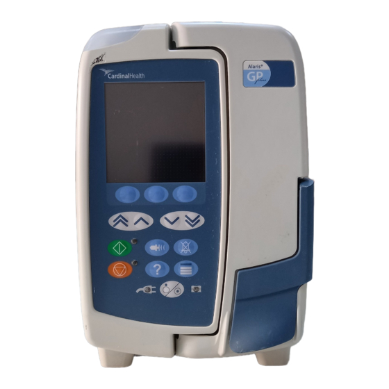
- Page 6 General Information Features of the Pump Alarm indicator Door Display Softkeys Chevrons Mute Bolus Hold Pressure Options Battery indicator AC power indicator On/Off Door Lever Handle Release lever for rotating cam Flow sensor connector (cover removed for clarity) RS232/Nursecall connector (cover removed for clarity) Rotating cam to lock onto Folded pole clamp...
- Page 7 General Information General Precautions Attention consult accompanying documents: Prior to using this pump, carefully read the Operating Precautions described in the Directions for Use (DFU). This pump contains static-sensitive components. Observe strict precautions for the protection of static sensitive components when attempting to repair and service the pump. An explosion hazard exists if the pump is used in the presence of flammable anaesthetics.
-
Page 8: Configuration & Calibration
Chapter 2 Configuration and Calibration In this Chapter Entering Service Mode Service Mode - Factory Defaults Service Mode - Configuration Service Mode - Data Set Transfer Service Mode - Calibration... - Page 9 Configuration and Calibration Entering Service Mode Warning - At no time should Service Mode be entered while the pump is connected to a patient. Service Mode should only be accessed by qualified and trained personnel. Service Mode can be accessed via a three-digit access code that is entered using the following procedure: 1.
- Page 10 Configuration and Calibration Service Mode - Factory Defaults Factory Defaults FACTORY DEFAULTS Select the required option using the f keys and the OK softkey. Default Data Set Replace the current data set with a default data Default Data Set set. Cold Start Confirm Cold Start Confirm Confirm clearing and resetting the data set and...
- Page 11 Configuration and Calibration Service Mode - Factory Defaults (continued) Clear CQI Log File CLEAR CQI LOG FILE 1. Press OK to confirm clearing the CQI Log File. WARNING! ****** ****** This will remove all instrument history and will restore the factory default data set by deleting the clinically approved installed data set.
- Page 12 Configuration and Calibration Service Mode - Configuration (continued) Software Versions Press OK to exit after verifying Software Version fitted, display will vary depending on software version fitted. SOFTWARE VERSIONS SOFTWARE VERSIONS 001.005.004 001.009.000 001.009.000 001.005.004 001.009.000 001.005.004 001.009.000 001.005.004 001.007.016 001.005.000 LANGUAGE 001.004.005...
- Page 13 Configuration and Calibration Service Mode - Configuration (continued) Language LANGUAGE ENGLISH 1. Select the required Language using the f keys. NORSK - NORWEGIAN 2. Press OK to confirm. DEUTSCH - GERMAN FRANCAIS - FRENCH Languages available will be dependant on the pump NEDERLANDS - DUTCH software version.
- Page 14 Configuration and Calibration Service Mode - Data Set Transfer Upload data set to an Alaris® GP Volumetric Pump Equipment required: • Alaris® GP Editor Software Kit (1000SP01310) - includes the Alaris® GP Transfer Tool • RS232 cable (1000SP01183) • USB to RS232 Converter cable (1000EL00979) - optional •...
- Page 15 Configuration and Calibration Service Mode - Calibration Zero Point Calibration CALIBRATION Select the required option using the f keys and the OK softkey. Wait for the pressure sensors to park. Zero Point Cal Ensure that an infusion set is not installed. Pressure Cal Press the START softkey.
- Page 16 Configuration and Calibration Service Mode - Calibration (continued) Pressure Calibration continued Pressure source (50ml/100ml syringe or similar device) Pressure Gauge Alaris® Vent to atmosphere Figure 2 - 1 Pressure Calibration Equipment Set Up Turn 3-way tap to close from atmosphere. Press the START softkey.
- Page 17 Configuration and Calibration Service Mode - Calibration (continued) Volumetric Calibration CALIBRATION Select the required option using the f keys and the OK softkey. Load the primed Infusion Set (60793) into the Pump and set-up Zero Point Cal as shown in Figure 2-2 below and adjust the fluid level so that the Pressure Cal meniscus is level with the zero mark.
- Page 18 Configuration and Calibration Service Mode - Calibration (continued) Battery Calibration CALIBRATION Select the required option using the f keys and the OK softkey. CAL to begin. Connect AC Mains to the Pump and press Zero Point Cal CALIBRATION When calibration is complete it will display Pressure Cal SUCCESS or CALIBRATION FAILURE.
-
Page 19: Preventative Maintenance
Chapter 3 Preventative Maintenance In this chapter Preventative Maintenance Visual Inspection Recommended Cleaning and Storage Updates Battery Test and Replacement Service Mode - Test Verification/PVP Performance Verification Procedure... - Page 20 Preventative Maintenance Preventative Maintenance To ensure the pump remains in good operating condition, routine and preventative maintenance inspections are required. Routine maintenance inspections should be performed by hospital/facility before each use, see Directions For Use for details. Preventative maintenance inspections should be performed at least every year. For the preventative maintenance inspection the following should be performed: •...
- Page 21 Preventative Maintenance Recommended Cleaning and Storage Cleaning the Pump: - Before the transfer of the Pump to a new patient and periodically during the use, clean the Pump by wiping over with a lint-free cloth lightly dampened with warm water and a standard disinfectant / detergent solution. Recommended cleaners are: Brand Concentration...
- Page 22 Preventative Maintenance Recommended Cleaning and Storage (continued) Cleaning the door: - Periodically during use (as per hospital policy), clean the door by wiping over with a lint-free cloth, lightly dampened with warm water and a standard disinfectant / detergent solution. Dry door before use. To aid cleaning of a door which has been heavily soiled, contaminated or if the door operation is not free moving, then the door may be removed (see procedure below) then immersed and soaked in warm water with a standard disinfectant / detergent.
- Page 23 Preventative Maintenance Updates Upgrading firmware Requirements • • Minimum hardware system requirements: Software requirements: • 1GHz Pentium processor • 512MB RAM • Microsoft Windows 2000 (service pack 4), or XP • 1GB of free space on the system hard • CD ROM drive (service pack 2) drive...
- Page 24 Preventative Maintenance Updates (continued) Upgrading firmware continued 8. Once the green bar has reached the far right hand side and the time has reached 0:00 and the flashing green light is a steady green light, the RS232 connector can be removed from the pump. 9.
- Page 25 Preventative Maintenance Battery Test and Replacement To test the battery perform the battery calibration, as outlined in the procedure in Chapter 2 ‘Configuration and Calibration’, and verify that all pass criteria are met. If pass criteria are not met then replace the battery. Battery charge retention will eventually degrade.
- Page 26 Preventative Maintenance Service Mode - Test Verification/PVP (continued) PVP Work Flow PVP WORK FLOW This test is used to confi rm that the Pump is functioning correctly. Press the START softkey to begin. PVP Work Flow Test The PVP Work Flow will iterate through the following tests: •...
- Page 27 Preventative Maintenance Service Mode - Test Verification/PVP (continued) Alarms Functionality ALARMS FUNCTIONALITY 1. Press the START softkey to begin. INFORMATION! **** ***** Ensure that a fluid filled set is in use. Subsequent alarm screens should be cleared using the CANCEL softkey. QUIT START 2.
- Page 28 Preventative Maintenance Service Mode - Test Verification/PVP (continued) User Interface USER INTERFACE Select the required option using the f keys and the OK softkey. Chequerboard Keypad Tests Chequerboard Display Chequerboard Test. Keypad Tests LED Tests Perform Keypad Test to check all keys work when Audio Tests pressed.
- Page 29 Preventative Maintenance Service Mode - Test Verification/PVP (continued) LED Tests LED TESTS 1. Press the START softkey to begin. 2. Check LEDs are displayed correctly and to pass. If an LED is not Safety Processor displayed then press to fail. Primary Red 3.
- Page 30 Preventative Maintenance Service Mode - Test Verification/PVP (continued) Power Supplies POWER SUPPLIES Select the required option using the f keys and the OK softkey. AC Mains Test Battery AC Mains Test Tests the AC mains removal detection. Battery Test the battery. To perform calibration see Chapter 2 'Configuration &...
- Page 31 Preventative Maintenance Service Mode - Test Verification/PVP (continued) Sensor Tests SENSOR TESTS In Sensor Tests menu select required test using the f keys and the OK softkey. Flow Sensor Test Door Frame Test Flow Sensor Test Check Flow Sensor is connected and drops Safety Clamp Test count.
- Page 32 Preventative Maintenance Service Mode - Test Verification/PVP (continued) Door Frame Test DOOR FRAME TEST 1. Press the START softkey to begin. 2. Check Door open/closed is correctly indicated and press softkey or press softkey if not correctly detected. Door Frame 3.
- Page 33 Preventative Maintenance Service Mode - Test Verification/PVP (continued) Air In Line Test AIR IN LINE TEST 1. Press the START softkey to begin. 2. Insert a fluid filled Infusion Set and an air filled Infusion Set. Upstream: INVALID 3. Confirm pump detects fluid and air correctly and press softkey or Detecting press...
- Page 34 Preventative Maintenance Service Mode - Test Verification/PVP (continued) Pumping Effi ciency Test PUMPING EFFICIENCY TEST This test is used to confi rm that the Pump is able to generate suffi cient pressure. This is done by infusing into a calibrated pressure gauge and checking that the correct line pressure is achieved.
- Page 35 Nurse Call Test Check Nurse Call operates correctly. IrDA Test requires specialist equipment. SELECT WITH For further details please contact Cardinal Health. QUIT RS232 Loop Back RS232 LOOP BACK 1. Link pins 2 & 3 of the RS232 connector on rear of the pump.
- Page 36 Preventative Maintenance Service Mode - Test Verification/PVP (continued) Occlusion Test This test can be only done as part of the PVP Work Flow. Use the Infusion Set ten times only and then replace. Record how many times the Infusion Set has been used. Note: The Occlusion Pressure Test is carried out with fl uid in the Infusion Set.
- Page 37 Preventative Maintenance Service Mode - Test Verification/PVP (continued) Volumetric Accuracy VOLUMETRIC CALIBRATION This test can be done as part of the PVP Work Flow or in the calibration menu. Load the Infusion Set (60793) into the Pump and set-up as shown in Rate 125ml/h Figure 3-2 below and adjust the fluid level so that the meniscus is...
- Page 38 Preventative Maintenance Performance Verification Procedure Model / Serial Number: Service Order / Inventory Number: Hospital Name / Reference: Software Version: INSPECTION Physical inspection and clean Check all functions in PVP Work Flow Enter access code 212 and go to PVP Work Flow •...
-
Page 39: Troubleshooting
Chapter 4 Troubleshooting In this Chapter Log Downloads Introduction Software Fault Codes General Fault Diagnosis Exception Error Handling... - Page 40 Troubleshooting Log Downloads PC Setup (first time only) Navigate through the Start menu, select Settings, then Network Connections. Select New Connection Wizard. Click Next. Select Set up an advanced connection option and click Next. Select Connect directly to another computer option and click Next. Select Guest option and click Next.
- Page 41 Troubleshooting Troubleshooting Introduction Use this troubleshooting guide to help identify the cause of errors and faults which may occur as a result of damage to the pump or failure of an internal component. The following table lists the error messages and describes what action to take to resolve the problem.
- Page 42 Troubleshooting Troubleshooting Software Fault Codes (continued) Module Failure Action/Replace Code MMI1 Primary Audio Fault Speaker, Control PCB or Interface PCB. MMI2 Stuck Key Fault_Stop MMI3 Stuck Key Fault_Start MMI4 Stuck Key Fault_OnOff MMI5 Stuck Key Fault_IncInc MMI6 Stuck Key Fault_Inc MMI7 Stuck Key Fault_Dec Key has been registered as stuck for 2...
- Page 43 Troubleshooting Troubleshooting General Fault Diagnosis Failure Action/Replace Display missing vertical lines No response from keypad or LED If Control PCB is issue 9 and below, then replace with latest issue Control PCB. Safety alarm is activated Failure of RS232 communications Replace Comms PCB.
-
Page 44: Circuit Descriptions
Chapter 5 Circuit Descriptions In this chapter Functional Module Block Diagram Module Overview Functional Description Module Overview Functional Description (continued) - Page 45 Circuit Descriptions Circuit Descriptions Functional Module Block Diagram CHASSIS GP PRESSURE PCB UPSTREAM INTERFACE PCB PRESSURE MEASUREMENT GP PRESSURE MODULE PCB DOWN STREAM ENCODER MOTOR INTERFACE ENCODER PCB MODULE FLUID DELIVERY DROP SENSOR PROCESSOR MODULE AIL/SAFETY MODULE CLAMP HOUSING AIR IN LINE MODULE THREE PHASE MOTOR DRIVE...
- Page 46 AIL/Safety Clamp Housing Motor Fluid Delivery Processor Module This module provides the interface between the motor Cardinal Health will make available, on request, circuit drive and sensor systems and the main processor. diagrams which will assist appropriately qualified technical Drop Sensor Module...
- Page 47 Circuit Descriptions Module Overview Functional Description (continued) Display PCB Door Detect Flexible PCB This is an ISTN negative mode graphics display with built The status of the door is monitored using a magnet in temperature compensation. embedded in the door frame and a digital Hall Effect device mounted on the end of the Door Detect Flexible Comms PCB and IrDA Flexible PCB PCB.
-
Page 48: Corrective Maintenance
Chapter 6 Corrective Maintenance In this chapter Corrective Maintenance Torque Guide Access To Pump Rear Case and Subassemblies Front Case and Subassemblies Keypads and Labels... - Page 49 Batteries should be disposed of as outlined by the local country regulations. Do not send batteries back to the manufacturer. Only use Cardinal Health recommended spare parts. This chapter contains procedures required to properly disassemble, repair and replace parts and then to reassemble the pump.
- Page 50 Corrective Maintenance Torque Guide this chapter, for example 40cNm. T The torque levels established during the manufacturing process are outlined in orque levels selected apply throughout product life Use the information as a guide to the 'do not exceed' torque levels when servicing the pump. When servicing, it is recommended that torque is applied gradually until the component is secure.
- Page 51 Spare parts Item Description Part Number Asena LVP Battery Pack 1000SP00487 Cover Battery Asena LVP 1000ME00589 Alaris GP Fastener Spares Kit 1000SP01252 Foot Battery Cover Asena LVP 1000ME00590 Foot Front Asena LVP 1000ME00649 Seal Case Nickel/graphite 1000ME01611 Alaris GP Rear Case Kit...
- Page 52 Corrective Maintenance Access To Pump (continued) (C) Screw/Washer (x5) 40cNm (H) Front Case kit (G) Rear Case kit (F) Case seal (C) Screw 70cNm (E) Feet (x2) Alaris® GP Volumetric Pump 52/84 1000SM00013 Issue 3...
- Page 53 6. Reassemble in reverse order. (C) Screw/Washer (x4) 40cNm (A) PSU Spare parts Item Description Part Number Alaris GP PSU PCB Kit 1000SP01305 Alaris GP Speaker KIt 1000SP01306 Alaris GP Fastener Spares Kit 1000SP01252 Pad Self Adhesive Double Sided 12x12mm...
- Page 54 (E) PE Stud Spare parts Item Description Part Number Alaris GP Mains Inlet Kit 1000SP01251 Alaris GP IrDA PCB Flexi Kit 1000SP01308 Alaris GP Fastener Spares Kit 1000SP01252 Magnet IR Detect 1000ME01303 Stud PE Connector M6 Thread X 15 0000ME00141 Bussmann Fuse Gmd-1.25A...
- Page 55 2. Reassemble in reverse order. (A) Pole Clamp (B) Bung (B) Screw (x3) 70cNm Spare parts Item Description Part Number Asena SP, Assy, Pole Clamp 1000SP00115 Alaris GP Fastener Spares Kit 1000SP01252 Alaris® GP Volumetric Pump 55/84 1000SM00013 Issue 3...
- Page 56 (A) Rail Cam Kit (C) Rail Cam only Kit (A) Rail Cam Kit Spare parts Item Description Part Number Alaris GP Docking Station Kit 1000SP01307 Alaris GP Fastener Spares Kit 1000SP01252 Alaris SP Cam Rail Clamp Only Kit 1000SP01323 Alaris® GP Volumetric Pump...
- Page 57 (C) Screw (x2) 40cNm (E) Fuse cover (A) RS232 Socket Screw (x2) 40cNm Spare parts Item Description Part Number Alaris GP Comms PCB Kit 1000SP01256 Cover RS232 1000ME01745 Alaris GP Fastener Spares Kit 1000SP01252 Asena GW, Assy, Cover Dust Drop Sensor 1000ME00291...
- Page 58 (B) Handle spring (A) Handle Spare parts Item Description Part Number Asena LVP Overmould Handle 1000ME01845 Handle Spring Asena LVP 1000ME00630 Asena LVP Handle Retaining Block 1000ME00632 Alaris GP Fastener Spares Kit 1000SP01252 Alaris® GP Volumetric Pump 58/84 1000SM00013 Issue 3...
- Page 59 4. Unscrew the two hinge pins. 5. Reassemble in reverse order. (B) Screw (x2) 70cNm (A) Membrane Spare parts Item Description Part Number Asena LVP Assembly Membrane 1000ME00667 Alaris GP Fastener Spares Kit 1000SP01252 Alaris® GP Volumetric Pump 59/84 1000SM00013 Issue 3...
- Page 60 Front Case and Subassemblies (continued) Door continued (A) Hinge pin (x2) 60cNm (A) Hinge pin seal (x2) (B) Door Spare parts Item Description Part Number Alaris GP Hinge Pin Kit 1000SP01246 Alaris GP Door Kit 1000SP01244 Alaris® GP Volumetric Pump 60/84 1000SM00013 Issue 3...
- Page 61 (B) Screw (x2) 65cNm (B) Snap rivet (A) Gasket (A) Roller mounting bracket Spare parts Item Description Part Number Alaris GP Roller Mounting Bracket Kit 1000SP01303 Alaris GP Fastener Spares Kit 1000SP01252 Alaris® GP Volumetric Pump 61/84 1000SM00013 Issue 3...
- Page 62 Item Description Part Number Alaris GP Motor Kit 1000SP01296 Alaris GP Fastener Spares Kit 1000SP01252 Alaris GP Pumping Mech (Minus Motor) Kit 1000SP01247 Alaris GP Pressure Sensor Kit 1000SP01254 V Seals Hinge Pins V5a-NBR 0000ME00767 Alaris® GP Volumetric Pump 62/84...
- Page 63 (B) Control PCB Pillar supports (x3) Spare parts Item Description Part Number Alaris GP Interface PCB Kit 1000SP01300 Alaris GP Control PCB Kit 1000SP01298 Alaris GP Fastener Spares Kit 1000SP01252 Note: Three Pillar Supports are supplied with both PCB kits.
- Page 64 3. Reassemble in reverse order. (A) Display (B) Display Frame Spare parts Item Description Part Number Alaris GP Display Kit 1000SP01255 Alaris GP Display Accessories Kit 1000SP01297 Alaris GP Fastener Spares Kit 1000SP01252 Alaris® GP Volumetric Pump 64/84 1000SM00013 Issue 3...
- Page 65 (A) Seal (B) Door Sensor (E) Seal (D) Top Retainer Spare parts Item Description Part Number Alaris GP AIL/Safety Clamp Housing Kit 1000SP01249 Door Detect Flexible Circuit 1000EL00643 Alaris GP Fastener Spares Kit 1000SP01252 Asena LVP GP Top Retainer 1000ME00701...
- Page 66 6. Ensure keypad membrane flexi tail is routed correctly. (A) Keypad Spare parts Item Description Part Number Alaris GP Keypad BOM 1000LB00623 Alaris GP Door Label Set 1000LB01040 Alaris GP Guardrails Door Label 1000LB01475 Alaris GP Label Set BOM 1000LB00614 Alaris® GP Volumetric Pump 66/84...
- Page 67 Corrective Maintenance Keypads and Labels (continued) Cardinal Health 1180 Rolle Switzerland 2 x T 1.25A 20 x 5 mm 250V 100 - 230V 50 - 60Hz 60VA (Max.) 1000LB00614 Iss 4 1000LB00614 Iss 4 ® Alaris GP Volumetric Pump Label Set...
-
Page 68: Electromagnetic Compatibility
Appendix A Electromagnetic Compatibility... - Page 69 Electromagnetic Compatibility Electromagnetic Compatibility Warning: • The use of any accessory, transducer, or cable with the Pump other than those specified may result in increased emissions or decreased immunity of the pump. • The Pump should not be used adjacent to or stacked with other equipment, however if adjacent or stacked use is necessary, the Pump should be observed to verify normal operation in the configuration in which it will be used.
- Page 70 Note 3—Performed at the Minimum and Maximum Rated Input Voltage. Note 4—Cardinal Health recommends using signal cables of less than 3 meters in length and this requirement is applicable only if signal cables are 3 meters or more in length. (EN 60601-1-2:2002, Clause 36.202.4) Alaris®...
- Page 71 Electromagnetic Compatibility Electromagnetic Compatibility (continued) Guidance and Manufacturer’s Declaration—Electromagnetic Immunity LIFE SUPPORT Equipment The Pump is intended for use in the electromagnetic environment specified below. The customer or the user of the Pump should ensure that it is used in such an environment. Immunity Test Compliance Level Electromagnetic Environment –...
- Page 72 Electromagnetic Compatibility Electromagnetic Compatibility (continued) Recommended Separation Distances for LIFE SUPPORT Equipment between portable and mobile RF communications equipment and the Pump The Pump is intended for use in an electromagnetic environment in which radiated RF disturbances are controlled. The user of the Pump can help prevent electromagnetic interference by maintaining a minimum distance between portable and mobile RF communications equipment (transmitters) and the Pump as recommended below, according to the maximum output power of the communications equipment.
-
Page 73: Disposal
Appendix B Disposal... - Page 74 If you wish to discard electrical and electronic equipment, please contact your Cardinal Health affiliate office or distributor for further information.
-
Page 75: Spare Parts Listings
Appendix C Spare Parts Listing In this chapter Spare Parts Kits Individual Components Keypad & Labels Software Test Equipment Kit Bill Of Materials (BOM) - Page 76 Part Number Description 1000SP01244 Alaris GP Door Kit 1000SP01246 Alaris GP Hinge Pin Kit 1000SP01247 Alaris GP Pumping Mech (Minus Motor) Kit 1000SP01248 Alaris GP Front Case Kit 1000SP01249 Alaris GP AIL/Safety Clamp Housing Kit 1000SP01250 Alaris GP Rear Case Kit...
- Page 77 0000ME00423 Pad Self Adhesive Double Sided 12x12mm Keypad & Labels Part Number Description 1000LB00623 Alaris GP Keypad BOM 1000LB01040 Alaris GP Door Label Set 1000LB00614 Alaris GP Label Set BOM 1000LB01475 Alaris GP Guardrails Door Label Software Part Number Description 1000SP01412 Alaris LVP GP F/ware Upgrade V1.7.18 Kit...
- Page 78 Alaris GP Door Label 1000SP01246 Alaris GP Hinge Pin Kit Assembly Insulated Door Hinge V Seals Hinge Pins V5a-NBR 1000SP01247 Alaris GP Pumping Mech (Minus Motor) Alaris GP Pumping Mech Rivet Snap 03 6.5/7.5 Panel Thickness V Seals Hinge Pins V5a-NBR...
- Page 79 Spare Parts Listing Kit Bill Of Materials (BOM) Description Description 1000SP01252 Alaris GP Fastener Spares Kit Plug Pull M12 Screw M3 X 8 Pan Washer Head With Patch Screw M3x8 Button Head With Patch Screw M3x8 Pan Hd T10 Skt & Flat Washer...
- Page 80 1000SP01301 Alaris GP Encoder PCB Kit Asena GP Motor Encoder PCB Flexi Encoder To Interface PCB Nylon Spacer 1000SP01303 Alaris GP Roller Mounting Bracket Kit Assembly Roller Mounting Bracket Gasket Assembly Roller LVP Screw M3x4 Cap Head Shoulder With Patch...
-
Page 81: Service Contacts
Appendix D Service Contacts... - Page 82 Service Contacts Service Contacts For service, contact your local Affiliate Office or Distributor. Cardinal Health, Cardinal Health, Cardinal Health, Cardinal Health, PO Box 5527, Pascalstr. 2, Döbrentei tér 1, Hammarbacken 4B, Dubai, United Arab 52499 Baesweiler, H-1013 Budapest, 191 46 Sollentuna, Emirates.
-
Page 83: Document History
Appendix E Document History... - Page 84 Document History Document History Issue Date CO No. Author Update Description 20/01/06 5999 Ian Tyler Initial release New Tech mode section. Spare Part Replacement Procedures chapter added. December 06 7111 Ian Tyler Troubleshooting chapter added. New Software features added. Spare Parts Listing appendix added. Introduce Calibration information.
Need help?
Do you have a question about the Alaris GP and is the answer not in the manual?
Questions and answers