Table of Contents
Advertisement
Quick Links
Advertisement
Table of Contents

Related Manuals for Polycom MGC Administrator


Summary of Contents for Polycom MGC Administrator
- Page 1 Administrator’s Guide Version 7.5...
- Page 2 Polycom, Inc. Information contained herein is subject to change without notice and does not represent commitment of any type on the part of Polycom, Inc. Polycom and Accord are registered trademarks of Polycom, Inc.
- Page 3 Canadian Department of Communications (EC) Declaration of Conformity Polycom, Inc. declares that the MGC-50/MGC-100 with NET-8 card is in conformity with the following relevant harmonized standards: EN 60950: 1992 Including Amendments 1,2,3 & 4 EN 55022: 1994 EN 50082: 1997 and follows the provisions of the Council Directive 1999/EC on radio and telecommunication terminal equipment and the recognition of its conformity.
-
Page 5: Table Of Contents
MGC Administrator’s Guide Table of Contents Before You Begin ........1-1 Scope of Manual . - Page 6 Table of Contents Defining ISDN Non-Facility Associated Signaling (NFAS) ..3-24 Assigning the ISDN Network Service to the NET-T1/NET-E1 Card ..........3-29 Assigning the ISDN Network Service to the Net-2/Net-4/Net-8 Card .
- Page 7 MGC Administrator’s Guide Viewing the IP/IP+ Card Properties ......4-16 Common Parameters ....... . . 4-17 IP-Network Parameters .
- Page 8 Table of Contents XPEK Silent Mode ........5-34 HTTP and FTP File Transfer Modes .
- Page 9 MGC Administrator’s Guide The Logger Files ........5-119 Retrieving the Logger Files .
- Page 10 Table of Contents Peripherals ......... 7-5 Network Alias .
- Page 11 MGC Administrator’s Guide H.320 Endpoint Over an H.323 Backbone to H.323 Endpoint, Using Profile (with TCS4) ....... . . 7-34 H.320 Endpoint Over an H.323 Backbone to H.320 Endpoint, Using...
- Page 12 Table of Contents Software Setup ..........B-1 COMMx .
-
Page 13: Before You Begin
Before You Begin Scope of Manual This manual describes the MGC Manager software installation, the configuration procedures and advanced system settings procedures. It is intended for service engineers and system administrators who need to configure, manage and maintain the MGC unit. Only users (MGC Manager operators) with Suppressor rights can perform MGC Manager configuration tasks. -
Page 14: Contents
Chapter 1 - Before You Begin Contents The MGC Administrator’s Guide includes the following chapters: Chapter 1 - Before You Begin • Provides a general description of the MGC unit, its system requirements and its prerequisites, and describes the topics and conventions to be found in this manual. - Page 15 MGC Administrator’s Guide Chapter 7 - Configuring the Gateway • Describes the various routing methods and provides step-by-step instructions for configuring the gateway. Chapter 8 - Audio and Video Conversion Tools • Describes how to use the Greet and Guide tools to create audio messages and video slides and how to convert them into the MGC format.
-
Page 16: Conventions
Chapter 1 - Before You Begin Conventions Before using this manual, it is important for you to understand the terms and conventions used: • The term “Double-click” is used when you need to activate a menu command or a command button in the dialog box. The term “Select”... -
Page 17: List Of Abbreviations
MGC Administrator’s Guide List of Abbreviations Following is the list of abbreviations used throughout this manual: Table 1-1: List of Abbreviations Application Programming Interface Channel Service Unit Dual Port Ram Electro-Static Discharge HDLC High-level Data Link Control High Speed Data Internet Protocol (H.323 and SIP) -
Page 18: Installation And Configuration Workflow
Hardware MGC Hardware Guide, Chapter 2 Installation MGC Hardware Guide, First Entry MCU Chapter 2 IP Configuration MGC Manager MGC Administrator’s Guide, Software Chapter 2 Installation MGC Administrator’s Guide, MGC Software Chapter 2 Upgrade (Only for users upgrading from a... -
Page 19: Software Installation
MCU(s) in the MGC Manager application. MGC Hardware Guide, Hardware Chapter 2 Installation MGC Hardware Guide, First Entry MCU Chapter 2 IP Configuration MGC Manager MGC Administrator’s Guide, Software Chapter 2 Installation MGC Software MGC Administrator’s Guide, Upgrade Chapter 2 MCU definition MGC Administrator’s Guide,... -
Page 20: Mgc Manager Software Installation
Chapter 2 - Software Installation Only users (MGC Manager operators) with Superuser rights can perform MGC Manager configuration tasks. In addition the user must have Superuser rights on the computer on which the MGC Manager application is running, or any other permission than enables the application to access the Registry (read/write) and read/write files on the C: drive (root directory) and under the Windows directory folder. - Page 21 MGC Administrator’s Guide The installation wizard starts and the Software License Agreement window opens. Click Yes to accept the software license terms. The Welcome screen opens. Read the notices and then click Next.
- Page 22 Chapter 2 - Software Installation The User Information screen opens. Type your name and the name of your company in the appropriate text boxes. For a standard installation, enter Polycom in the Serial box. Click Next. The Choose Destination Location screen opens.
- Page 23 MGC Administrator’s Guide Select the directory in which to install the MGC Manager software. To accept the default directory, click Next. To change the directory, click Browse, choose the directory in which to install the software, and then click Next.
- Page 24 Chapter 2 - Software Installation To change an installation setting, click Back until the appropriate screen appears. Click Next to start copying the files to your hard disk. When the installation procedure has finished, the Setup Complete screen opens. 10. Click Finish. The MGC Manager software is now installed on your computer.
-
Page 25: First Entry Ip Configuration
MGC Administrator’s Guide First Entry IP Configuration During the hardware installation process, a network IP address should have been assigned to the MCU. The IP address must be properly assigned to the MCU in order for the MGC Manager to connect to it. For more information about First IP Configuration on the MCU, refer the MGC Hardware and Installation Guide, Chapter 2. - Page 26 Chapter 2 - Software Installation The Add MCU dialog box opens. In the Name box, enter the name of the MCU. Specify a name that clearly identifies the MCU. In the IP Address box type the IP Address of the MCU. The IP address must be identical to the one configured in the MCU during first IP Configuration.
- Page 27 MGC Administrator’s Guide The Port Number field, and the Automatic Discovery and Secured check boxes, appear in the Add MCU dialog box. The Port Number field identifies the MCU port to which the MGC Manager initially connects. If the Automatic Discovery option is enabled, then after initially connecting to the MCU, the system checks the system configuration file (system.cfg) for the preferred port settings.
-
Page 28: Defining A Secured (Ssl) Connection To The Mcu
Chapter 2 - Software Installation The Add MCU dialog box closes. A new icon with the specified MCU name appears in the Browser pane, below the MCUs Network icon. To connect to an MCU, see the MGC Manager User's Guide, Volume I, Chapter 3, “Connecting to an MCU”. - Page 29 MGC Administrator’s Guide To obtain the SSL certificate: Connect to the MCU. Right-click the unit’s icon or name, and then click Create SSL Certificate Request. The Create SSL Certificate Request dialog box opens, where you can enter data for the request and apply.
- Page 30 Chapter 2 - Software Installation Enter information for all the following fields, as they are mandatory for the request: Table 2-1: SSL Certificate Request - Required Information Field Description Country Enter any 2 letter code for the country name. State or Province Enter the full name of the state or province.
- Page 31 MGC Administrator’s Guide In the browser, access your preferred certificate authority (for example, http://www.thawte.com and select from the quick login box: Certificate Status), paste the certificate request from MCU and submit. The authority issues the SSL certificate, and sends the certificate by text to you by E-mail.
- Page 32 Chapter 2 - Software Installation 10. Click Send. The MCU validates the certificate. — If the certificate is not valid, an error message appears. — If the certificate matches the private key, and the task is completed, a confirmation message indicating that the certificate was created successfully is displayed.
- Page 33 MGC Administrator’s Guide Click Advanced. The Port Number field, and the Automatic Discovery and Secured check boxes, appear in the Properties dialog box. Clear the Automatic Discovery check box. In the Port Number box that is enabled, enter port 443.
-
Page 34: Viewing The Mcu Connection Type In The Mgc Manager
Chapter 2 - Software Installation 10. Connect to the MCU. When reconnected, the MCU uses the secured port. After reconnecting, it is highly recommended to change the login password. Viewing the MCU Connection Type in the MGC Manager Application When mandatory security is enabled, on first connection after the reset, the MCU will automatically use only the preferred SSL-secured port 443, and the HTTPS protocol. -
Page 35: Mgc Configuration - Setting The Mcu Date And Time
MGC Administrator’s Guide MGC Configuration - Setting the MCU Date and Time The first time you install the MCU, if you are moving the MCU to a different location, or if the MCU is located in a different time zone from the MGC Manager, you have to set the MCU date and time to synchronize the MGC Manager. - Page 36 Chapter 2 - Software Installation The MCU GMT Time dialog box opens. The Use NTP Server check box and field is only displayed in XPEK Systems. You cannot set the MCU’s time or connect to the NTP server, when there are On Going conferences on the bridge.
- Page 37 MGC Administrator’s Guide Table 2-2: MCU GMT Time Options Field Description MCU GMT Offset Displays the currently defined time zone difference. To manually modify the GMT Offset, click on the scroll arrows to change the value, or enter the new value.
-
Page 38: Modifying The Mcu Local Time For Daylight Savings
Chapter 2 - Software Installation To set the time on the MCU automatically, using the MGC Manager time settings: Click the Get Oper Time&GMT button or Get Oper Time button. Click OK. To set the time on the MCU Manually: In the MCU GMT Time box, enter the appropriate MCU GMT time by either clicking on the scroll arrows to change the value, or retyping the new value. -
Page 39: Mgc Unit Software Installation
MGC Administrator’s Guide MGC Unit Software Installation When upgrading the software from a previous version, you need to download the new MCU version to the MCU unit. This process may also be required when replacing or upgrading the control unit of the MCU. - Page 40 Chapter 2 - Software Installation A message is displayed reminding you that you must have a valid dongle attached to the MCU. Click OK. The Logon dialog box opens. The Login Name and Password of the current logged in operator are entered by default.
- Page 41 MGC Administrator’s Guide You can download software to all MCUs listed in the MCU List in one operation. Make sure that all MCUs to update appear in the MCU List. To add an MCU to the list: Click the Add MCU button.
- Page 42 Chapter 2 - Software Installation This folder is named Vaaa.bbb, where aaa is the MGC Manager version number, and bbb is the MCU version number. You need to select the folder containing the latest version number, and not the sub-folder labeled Disk 1. Click OK.
- Page 43 MGC Administrator’s Guide To install only selected files, do the following: Click the Custom button. The Custom dialog box opens listing the files that can be installed on the MCU. All the files are checked (selected). Only checked files are copied to the MCU.
-
Page 44: Dongle Information
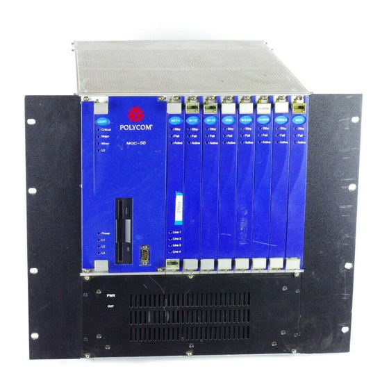
Chapter 2 - Software Installation Dongle Information The MGC-50/100 is shipped with a serial dongle installed on COM1 of the rear panel. The MGC-25 is shipped with a serial dongle installed on parallel port of the rear panel. To verify if you have a dongle your are required to inspect the rear panel of the MCU as shown in Figure 3. - Page 45 Each dongle installed on the MCU is backward compatible with current or previous MGC Manager versions. Only customers with an active Polycom Premier Family Maintenance Agreement are entitled to upgrade a version for free. When upgrading the MGC Manager version, you are required to upgrade your Dongle.
-
Page 46: Manual Installation Of The Default Message Services
Chapter 2 - Software Installation Manual Installation of the Default Message Services The MGC software kit is shipped with the voice messages required for the default Entry Queue Service and the default IVR Message Service. These messages can be automatically installed on the MCU during the software installation. - Page 47 MGC Administrator’s Guide If you have selected Browse, the Browse for Folder dialog box opens, enabling you to select the source folder. From the version 7.5x software folder, select English V75 IVR or English and Spanish V75 IVR folder, according to the required Message Service, and click OK.
- Page 48 Chapter 2 - Software Installation After the completion of the upgrade process, you must manually update the Existing Entry Queue Services by adding the voice message files prompting for the conference Numeric ID, otherwise the participants are placed on hold and cannot move to the target conferences.
-
Page 49: Command Line Launch
Windows Registry Access The Windows Registry uses the following format: HKEY_LOCAL_MACHINE \ SOFTWARE \ POLYCOM \ MGC_MANAGER \ Versions\VerX.Y MGC Manager launch format requires the full path and name of the specific MGC Manager version, including IP, MCU name, User login and password. - Page 50 Chapter 2 - Software Installation 2-32...
-
Page 51: Defining Network Services
Defining Network Services Providers of communication services such as telephone carriers use different Hardware communication protocols, lines, equipment and configurations. This can be Installation true even in different regions of the same country. The MGC unit is designed to work with different service providers/ communication lines. -
Page 52: Defining Network Services
Chapter 3 - Defining Network Services ISDN Network Service The Net-2/4/8 Network card installed in the MCU interfaces between the MGC unit and the ISDN switch. The Network Service is used to define the properties of the switch and the ISDN lines running from the switch to the ISDN Network card. -
Page 53: Defining An Isdn Network Service
MGC Administrator’s Guide Defining an ISDN Network Service The MCU may be connected to ISDN lines provided by different carriers. Each carrier has unique characteristics, and may have different pricing programs. To use these lines, together with the carrier’s special programs, you need to first obtain the relevant information from the carrier and then define their parameters in the MGC Manager application. -
Page 54: Settings Dialog Box
Chapter 3 - Defining Network Services The New Network Services configuration wizard opens. The wizard displays a series of dialog boxes. — To display the next dialog box, click on Next. — To display the previous dialog box, click Back. Settings Dialog Box The first dialog box displayed by the wizard is used to identify the network service to the system. - Page 55 MGC Administrator’s Guide Table 3-1: Settings Dialog Box Options Field Description Span Type Spans are ISDN lines supplied by the service provider to the MCU. You can define each span as a separate Network Service, or you can define all the spans from the same carrier under the same Network Service.
-
Page 56: Pri Settings Dialog Box
Chapter 3 - Defining Network Services PRI Settings Dialog Box The the PRI Settings dialog box enables you to define the properties of the PRI Service Type. If you do not need to define a sub-service, you can use the defaults, and just Next click to display the subsequent dialog box. -
Page 57: Pri Settings Dialog Box
MGC Administrator’s Guide Table 3-2: PRI Settings Dialog Box Options Field Description Num-plan Set the type of signaling (Number Plan) that the MGC unit will use for this service—for example, ISDN or telex. Enter the number plan according to information given by the service provider. -
Page 58: Defining Sub-Services
Chapter 3 - Defining Network Services If you are not defining a sub-service or if you have completed the sub- service definition, click Next to continue. The Span Definition dialog box opens. Defining Sub-Services 10. This step is required only if your ISDN network includes a sub-service, otherwise, skip these steps. - Page 59 MGC Administrator’s Guide Table 3-3: Sub Service Dialog Box Options Field Description Information For future release. Element Net Specific Select the desired service program from the drop- down list. The service programs are listed according to the service providers. If no special specification is required, select the NULL option.
-
Page 60: Span Definition Dialog Box
Chapter 3 - Defining Network Services Span Definition Dialog Box The Span Definition dialog box is used to define the PRI span technical properties. The default values displayed for the Span’s technical parameters are appropriate for most ISDN networks, therefore, you can skip their definition by clicking Next to move to the subsequent window. - Page 61 MGC Administrator’s Guide Table 3-4: Span Definition Dialog Box Options Field Description Framing (cont.) If a span type of T1 is specified in the Settings dialog box, the following Framing values are available: • ESF (Extended Super Frame format of 24 frames, which provides enhanced performance).
- Page 62 Chapter 3 - Defining Network Services Table 3-4: Span Definition Dialog Box Options Field Description Framing (cont.) If a span type of T1 is specified in the Settings dialog box, the following Framing values are available: • ESF (Extended Super Frame format of 24 frames, which provides enhanced performance).
- Page 63 MGC Administrator’s Guide Table 3-4: Span Definition Dialog Box Options Field Description Side Select the desired option from the drop-down list. The following options are available: • User side (default) • Network side • Symmetric side Note: If the PBX is configured on the network side, then...
- Page 64 Chapter 3 - Defining Network Services Table 3-4: Span Definition Dialog Box Options Field Description Switch Type Select the desired brand and revision level of equipment installed in the telephone company’s central office. If T1 is specified as the span type, the following Switch Type values are available: •...
-
Page 65: Spans And Phones Dialog Box
MGC Administrator’s Guide 12. Click Next to continue. The Spans and Phones dialog box opens. Spans and Phones Dialog Box This dialog box is used to assign circuit identification numbers and the dial-in phone number ranges to be used in dial-in conferences. Circuit orders are automatically assigned to spans. -
Page 66: Defining Spans
Chapter 3 - Defining Network Services 13. Define the Spans and Phones parameters as follows: Table 3-5: Spans and Phone Dialog Box Options Field Description Span Displays the existing definitions of circuit identification numbers and circuit orders. If only one service provider is used, define all the PRI lines here. - Page 67 MGC Administrator’s Guide The Add Span dialog box opens. Define the Circuit ID parameters: Table 3-6: Add Span Dialog Box Options Field Description Circuit ID The Circuit Identification is a logical number used to identify the span to the MGC Manager. This number is later used to assign the span to the network card.
-
Page 68: Defining Dial-In Numbers
Chapter 3 - Defining Network Services The Add Span dialog box closes and you are returned to the Spans and Phones dialog box. To delete a circuit identification entry: In the Spans pane, click the Circuit Identification entry you want to •... -
Page 69: Defining The Gateway Range
MGC Administrator’s Guide The dialog box closes. You are returned to the Spans and Phones dialog box. The number range appears in the Dial-In Phone Numbers list. Repeat steps a-d for each number range you need to enter. To delete a dial-in number entry: In the Dial In Phone Number section, click the entry to delete and then •... -
Page 70: Completing The Isdn Network Service Definition
Chapter 3 - Defining Network Services In the First Phone Number box, enter the first number in the range of gateway dial-in numbers. In the Last Phone Number box, enter the last number in the range of gateway dial-in numbers. Click OK. - Page 71 MGC Administrator’s Guide The Network Service wizard displays the Settings dialog box. Define the Net Service Name and Span Type as you would for a standard line. For details, see “Settings Dialog Box” on page 3-4. In the Service Type list, select Leased-24 for T1, or Leased-30/ Leased-31 for E1.
- Page 72 Chapter 3 - Defining Network Services The Span Definition dialog box opens. Define the applicable span technical properties in the left pane of the dialog box. For details, see “Span Definition Dialog Box” on page 3-10. The Leased Lines pane of the Span Definition dialog box is used to configure leased lines.
- Page 73 MGC Administrator’s Guide Leased lines are communication lines that are dedicated to specific participants. In the Leased Lines dialog box, you select the participants that will be assigned to this line. The number of ports allocated to each participant determines the line rate to be used in multiples of 64 Kbps, and it depends on the endpoint capabilities.
- Page 74 Chapter 3 - Defining Network Services Click Next to continue. The Spans and Phones dialog box opens. When defining leased lines, the Dial In Phone Num pane is disabled, as there is no need to define dial-in phone numbers. The participants are connected directly.
-
Page 75: Defining Isdn Non-Facility Associated Signaling (Nfas)
MGC Administrator’s Guide Defining ISDN Non-Facility Associated Signaling (NFAS) Non-Facility Associated Signaling (NFAS) only applies to T1 lines and can be configured in two different ways, depending on the ISDN network cards installed in your MCU. Each T1 span has 23 B channels for transferring audio, video, or data and one D channel. - Page 76 Chapter 3 - Defining Network Services To define an NFAS Network Service: In the Settings dialog box select the NFAS check box. Define the remaining settings parameters as described for standard PRI lines. For details, see “Settings Dialog Box” on page 3-4. Select Next.
- Page 77 MGC Administrator’s Guide The Spans and Phones dialog box opens, displaying the NFAS ID field in the Spans pane. In the Spans pane, click the Plus button. The Add Span dialog box opens. 3-27...
- Page 78 Chapter 3 - Defining Network Services Enter Circuit ID numbers for each span, as per PRI lines. The Circuit Order is assigned automatically by the system according to the order in which the spans are added. You can change the span order (if there are several spans defined in the system) using the Set Before or Set After buttons.
- Page 79 MGC Administrator’s Guide 10. Click OK. The Add Span dialog box closes and you are returned to the Spans and Phones dialog box. 11. To define additional NFAS spans, repeat steps 3 to 7. 12. Define the dial-in phone ranges as described in “Defining Dial-In Numbers”...
-
Page 80: Assigning The Isdn Network Service To The Net-T1/Net-E1
Chapter 3 - Defining Network Services Assigning the ISDN Network Service to the NET-T1/NET-E1 Card To connect the MCU to the ISDN network, you need to configure the Network Interface Module in conjunction with the ISDN Network Services defined in the MGC Manager. The label on the Network functional module indicates the card type. - Page 81 MGC Administrator’s Guide In the Browser pane, right-click the slot containing the Net-E1/T1 card, indicated by PRI48 and PRI64, and then click Properties. Alternatively, double-click the slot containing the card. The Card Settings – Common Parameters dialog box opens. The Common Parameters describe the basic card settings; Slot Number, Card Type, Hardware Version Number, Software Version Number, and Serial number.
- Page 82 Chapter 3 - Defining Network Services The Status box displays all error messages relating to the card. The Conference box displays the names of conferences that are currently being run by this card. Click the Network Parameters tab. The Card Settings - Network Parameters dialog box opens, displaying the settings that are specific to the Net-T1/Net-E1 Network Interface module.
- Page 83 MGC Administrator’s Guide For the system to recognize the PRI line that connects to the Net-T1/Net- E1 Network Interface card you have to assign the PRI line's circuit ID as defined in the ISDN Network Services to the Net-T1/Net-E1 Network Interface module.
- Page 84 Chapter 3 - Defining Network Services Right-click the unit you want to configure. Depending on the card clock source assignment (if primary or backup) the following options appear. Click the desired option. Table 3-7: Network Interface Unit (ISDN) - Configuration Options Option Description Set as Primary...
-
Page 85: Assigning The Isdn Network Service To The Net-2/Net-4/Net-8
MGC Administrator’s Guide Assigning the ISDN Network Service to the Net-2/Net-4/Net-8 Card In order to connect the MCU to the ISDN network switch, you need to assign the ISDN Network Service to the appropriate span of the Net-2/Net-4/Net-8 Network Interface module. In addition, you may define which span in the network interface card will be used as the primary clock and which one as the backup clock to synchronize with the network clock. - Page 86 Chapter 3 - Defining Network Services In the Browser pane, right-click the slot containing the Net-2/4/8 card, and then click Properties. Alternatively, double-click the slot containing the card. The Card Settings – Common Parameters dialog box opens. The Common Parameters describe the basic card settings: Slot Number, Card Type, Hardware Version Number, Software Version Number, and Serial number.
- Page 87 MGC Administrator’s Guide Click the Net-8 Network Parameters tab. The Card Settings - NET-8 Network Parameters dialog box opens, displaying the settings that are specific to the Net-2/Net-4/Net-8 Network Interface module. The Net-2/Net-4/Net-8 Network Interface module supports up to eight PRI connections depending on the card model installed in the MCU.
- Page 88 Chapter 3 - Defining Network Services To assign a Circuit ID to the appropriate span: In the Span n box (where n is the span number on the Net-2/Net-4/ Net-8 module to which the PRI line is connected), clear the Null Configuration check box to enable the span.
- Page 89 MGC Administrator’s Guide Right-click the unit (span) to configure. A menu appears. Click one of the following options to set up the clock source for the system. Table 3-8: Net-2/Net-4/Net-8 Unit Configuration Options Option Description Set as Primary Sets this unit as the primary clock source. For Clock Source further information, see Chapter 5, “Clocking”...
-
Page 90: Defining A T1-Cas Network Service
Chapter 3 - Defining Network Services Defining a T1-CAS Network Service Channel Associated Signaling (CAS), is a method of signaling performed on a traffic channel rather than on a dedicated signaling channel (as in ISDN). T1-CAS Network Service allows connection of Audio Only participants and is intended for VoicePlus configurations or MCUs running Audio Only conferences using T1-CAS lines. -
Page 91: Defining A New T1-Cas Network Service
MGC Administrator’s Guide Defining a new T1-CAS Network Service In the Browser pane, expand the MCU tree, and then expand the MCU Configuration tree. Expand the Network Services tree. Right-click the Network Services - T1-CAS icon, and then click New T1-CAS Service. - Page 92 Chapter 3 - Defining Network Services Define the following parameters: Table 3-9: Settings Dialog Box Options Field Description T1-CAS Service Specify the service name using up to 20 Name characters. The Network Service Name identifies the service to the system. Framing Framing refers to the frame format used by the carrier for the network interface.
- Page 93 MGC Administrator’s Guide Table 3-9: Settings Dialog Box Options Field Description RCV Threshold This option is used to increase the signal on T1 spans when the system detects a very low signal. Select the desired threshold values from the list: •...
- Page 94 Chapter 3 - Defining Network Services Circuit orders are automatically assigned to spans. The dial-in phone numbers are allocated to the MCU by the service provider (carrier). Gateway Sessions are not supported with T1-CAS lines. Define the Spans and Phones parameters as follows: Table 3-10: Span and Phone Dialog Box Options Field Description...
- Page 95 MGC Administrator’s Guide Define the Circuit Id. Table 3-11: Add Span Dialog Box Options Field Description Circuit ID The Circuit Identification is a logical number used to identify the span to the MGC Manager. This number is later used to assign the span to the network card.
-
Page 96: Completing The T1-Cas Network Service Definition
Chapter 3 - Defining Network Services The Add Phone Num dialog box opens. Enter the first number and the last number in the phone numbers range and click OK. The phone numbers range is added to the Dial-in Phones pane of the Spans and Phones dialog box. -
Page 97: Assigning The T1-Cas Network Service To The Net-2/Net-4/Net-8
MGC Administrator’s Guide Assigning the T1-CAS Network Service to the Net-2/Net-4/Net-8 Card In order to connect the MCU to the network switch, you need to assign the T1-CAS Network Service to the appropriate span of the Net-2/Net-4/Net-8 Network Interface module. - Page 98 Chapter 3 - Defining Network Services The Card Settings – Common Parameters dialog box opens. The Common Parameters describe the basic card settings. The Status box displays all the error messages related to the card. The Conferences box displays the names of conferences which are currently active.
- Page 99 MGC Administrator’s Guide The Card Settings NET-8 Network Parameters dialog box opens. The Net-2/Net-4/Net-8 Network Interface module supports 2/4/8 T1-CAS spans depending on the card model. Any of these spans may be set as the “master clock,” which synchronizes the system clock to the network clock, or “backup clock, which is used if the master clock fails.
- Page 100 Chapter 3 - Defining Network Services In the Circuit ID box, enter the circuit ID as defined in the Network Service–Spans and Phones dialog box. According to the selected Circuit ID, the Network Service is assigned to the network card. Each span can be assigned a different Network Service.
- Page 101 MGC Administrator’s Guide Click one of the following options to set up the clock source for the system. Table 3-12: Net-2/Net-4/Net-8 Unit Configuration Options Option Description Set as Primary Sets this unit as the primary clock source. For Clock Source further information, see Chapter 5, “Clocking”...
-
Page 102: Defining An Ip Network Service
Chapter 3 - Defining Network Services Defining an IP Network Service The IP Network Service defines the properties of the IP network used for connecting IP endpoints to the conference and the IP cards (installed in the MCU) to which the network is connected. Several of the network components are used by both H.323 and SIP endpoints to connect to the conference, and the same IP card is used for H.323 and SIP connections. - Page 103 MGC Administrator’s Guide H.323 H.323 is a standard for audio, video, and data communications across IP-based (LAN) networks, including the Internet. The H.323 network includes four main components: H.323 endpoints, gateway, gatekeeper, and MCU with an IP card. The gateway and MCU may be in one unit or two separate units.
- Page 104 Chapter 3 - Defining Network Services Session Initiation Protocol (SIP) is an application-layer protocol designed to work over IP networks that can establish, modify, and terminate multimedia sessions (conferences). The SIP network includes the following components: SIP endpoints, DNS, SIP Server, and MCU with an IP card. SIP Endpoint SIP Server ISDN...
-
Page 105: Defining An Ip Network Service
MGC Administrator’s Guide Defining an IP Network Service Conferencing with H.323 and SIP endpoints requires the presence of various components in the IP environment. Several components are common to both H.323 and SIP connections and others are unique to H.323 or SIP. - Page 106 Chapter 3 - Defining Network Services belong to the same subnetwork. H.323 entities are serviced by the same gatekeeper, while SIP entities are serviced by the same SIP server. You can also define an H.323-only Network Service that includes only H.323 entities and a SIP-only Network Service that includes only SIP entities.
- Page 107 MGC Administrator’s Guide The Setting dialog box opens. Define the following fields: Table 3-15: Settings Dialog Box Options Field Description Service Name Specify the service name using up to 20 characters. The Network Service Name identifies the service to the system.
- Page 108 Chapter 3 - Defining Network Services Table 3-15: Settings Dialog Box Options Field Description Protocol Select: • H.323: For an H.323-only Network Service. Only H.323 participants can connect to the MCU using this service. • SIP: For a SIP-only Network Service. Only SIP participants can connect to the MCU using this service.
- Page 109 For more details, see “Subnet Mask” on page E-2. The detected number appears in the card’s Properties-Settings-IP Network Parameters dialog box. For more details, see the MGC Administrator’s Guide, Chapter 4. Default Router Enter the IP address of the default router. If the...
- Page 110 Chapter 3 - Defining Network Services Table 3-15: Settings Dialog Box Options Field Description Static Routes Routes Table Displays the list of static routes currently defined in the system. Up to five routers can be defined in addition to the Default router. The order in which the routers appear in this list determines the order in which the system will look for the endpoints on the various networks, if not found on the local LAN.
- Page 111 MGC Administrator’s Guide Defining Static Routes To define a static route: Click the plus [+] button. The Add Route dialog box opens. Two router types can be defined: Network and Host. A Host router provides a direct connection to a specific host (an endpoint) located in another subnetwork.
- Page 112 Chapter 3 - Defining Network Services Table 3-16: Add Router Dialog Box Options (Continued) Field Description Type Select the type of router connection: • Network – defines a connection to a router segment in another network. • Host – defines a direct connection to an endpoint found on another network.
- Page 113 MGC Administrator’s Guide Define the following fields: Table 3-17: QoS of Ethernet Service Dialog Box Options Field Description Enable Select the Enable check box to implement QoS for marking outgoing IP packets, either according to the DiffServ standard or the IP Precedence mechanism.
- Page 114 Chapter 3 - Defining Network Services Table 3-17: QoS of Ethernet Service Dialog Box Options (Continued) Field Description Audio and Video You can prioritize audio and video IP packets to ensure that all participants in the conference hear and see each other clearly. Select the desired priority.
- Page 115 MGC Administrator’s Guide Click Next. The DNS Settings dialog box opens. This dialog box is used to define the DNS Server IP address and the local domain name. For H.323 conferencing, DNS is used if gatekeeper discovery using the gatekeeper host name and NAT auto-discovery are applied. Using NAT...
- Page 116 URL or URI (the part of the host’s address that appears after the at sign (@), or in a URL the part following the www. prefix), for example, polycom.com. This field is used both for SIP proxy registration purposes and DNS resolution and therefore it is required if you are using DNS servers in this service.
- Page 117 MGC Administrator’s Guide 10. Click Next. The H.323 dialog box opens. This dialog box is skipped when defining a SIP-only Network Service. 11. Define the following parameters: The following table describes the gatekeeper modes that can be configured with each of the listed gatekeepers.
- Page 118 Chapter 3 - Defining Network Services Table 3-19: H.323 Dialog Box Parameters Field Description Forwarding Select this check box to enable Forwarding. Forwarding enables the MCU to indicate the IP address of another card for handling the incoming call when the first card is busy. The advantage of Forwarding is that it can be used when no gatekeeper is involved, or when a special Service Mode, such as Basic, is used.
- Page 119 MGC Administrator’s Guide Table 3-19: H.323 Dialog Box Parameters (Continued) Field Description Port Port 1719 is the most common port that gatekeepers listen to and transmit through. Service Mode Each card registers with the gatekeeper with its IP address and/or alias. The gatekeeper routes calls to the card with available resources.
- Page 120 Chapter 3 - Defining Network Services Table 3-19: H.323 Dialog Box Parameters (Continued) Field Description Service mode To use the Board Hunting mode and route calls to (cont.) an available IP card, the dialed string must begin with the IP Service prefix. When this format is used for dial-in, the prefix can be followed by a conference/ Meeting Room numeric ID or name.
- Page 121 MGC Administrator’s Guide Table 3-19: H.323 Dialog Box Parameters (Continued) Field Description Service Mode Note: In current Cisco implementations when (cont.) there is more than one IP card in use, the gatekeeper selects one of the boards that are registered with the dialed string. Thus the system does not automatically forward the calls to an available card.
- Page 122 Chapter 3 - Defining Network Services Table 3-19: H.323 Dialog Box Parameters (Continued) Field Description Prefix (cont’) Notes: • When PathNavigator is used, this prefix automatically registers with the gatekeeper. When another gatekeeper is used, this prefix must also be defined in the gatekeeper. •...
- Page 123 MGC Administrator’s Guide 12. Click Next to continue to the SIP dialog box. This dialog box is skipped when defining an H.323-only Network Service. 3-73...
- Page 124 Chapter 3 - Defining Network Services 13. Define the following parameters: Table 3-21: SIP Dialog Box Options Field Description Servers Get SIP Servers Select this option to automatically retrieve the IP Automatically address of the SIP servers. This option is enabled if a DHCP or a DNS server is enabled and the local domain name is defined (as it is required for locating the SIP proxy).
- Page 125 MGC Administrator’s Guide Table 3-21: SIP Dialog Box Options (Continued) Field Description Registration Mode • Polling – Each IP card is registered in the proxy (cont.) with all the conferences and each card is assigned a priority per conference. The proxy directs the incoming call to one of the registered cards.
- Page 126 Chapter 3 - Defining Network Services Table 3-21: SIP Dialog Box Options (Continued) Field Description Refresh SIP Enter the frequency in which the system informs the Registrations Every SIP proxy that it is active by re-sending the details of n Seconds all conference types to the server.
- Page 127 MGC Administrator’s Guide Table 3-22: Registration Modes—Pros and Cons (Continued) Factor/Mode Redirect Polling Forking Success rate: With which method the If there is a Highest incoming call will be problem with connections successful connecting to the IP card, it rate.
-
Page 128: Defining Sip Servers
Chapter 3 - Defining Network Services Defining SIP Servers 14. To configure the SIP servers manually: Click the SIP Servers button. The SIP Settings dialog box opens. It is important to know which protocol the SIP proxy uses, as there are proxies that can work with only one type of protocol. - Page 129 MGC Administrator’s Guide Define the following parameters: Table 3-24: SIP Settings Dialog Box Options Field Description Transport SIP Transport Type Select the protocol that is used for signaling between the MCU and the SIP proxy or the endpoints according to the protocol supported by the SIP proxy: •...
- Page 130 EQ1@polycom.com reaches its the outbound proxy, this proxy looks for the SIP server in the polycom.com domain to which it will forward the call. When this call arrives to the SIP server in polycom.com, the server looks for the registered user (EQ1) and forwards the call to this Entry Queue or conference.
- Page 131 MGC Administrator’s Guide Table 3-24: SIP Settings Dialog Box Options (Continued) Field Description Outbound Proxy Outbound Proxy is Select this check box if the outbound proxy is different than SIP installed on a different computer than the one the SIP Server server is installed on.
- Page 132 Chapter 3 - Defining Network Services The Security dialog box opens. The Security dialog box lists the authenticated entities registered with the preferred proxy. Authentication is the method used by the SIP proxy to validate the identity of the MCU and its Entry Queues and Meeting Rooms. When registering with the proxy, the MCU must provide the user name and password as configured and predefined in the SIP proxy.
- Page 133 MGC Administrator’s Guide To add authenticated users to this list, click the plus [+] button. The Authentication dialog box opens. Define the authentication parameters of the Entry Queue or Meeting Room as registered with the SIP proxy. Table 3-25: Authentication Dialog Box Options...
- Page 134 Chapter 3 - Defining Network Services Click OK to add this user (UA) to the authenticated users list, and return to the Security dialog box. 16. Click Next. The Span dialog box opens. This dialog box lists the currently defined spans to be used with the defined Network Service.
- Page 135 MGC Administrator’s Guide afterwards when assigning the Network Service to the IP card (for details see “Assigning Network Services to the IP/IP+ Cards” on page 3-93). To delete an existing span, select it and click the minus (-) button. Adding a Span To add a span click the plus [+] button.
- Page 136 Chapter 3 - Defining Network Services Define the following fields: Table 3-26: IP SPAN Dialog Box Options Field Description Circuit ID The circuit identification is a number used to identify the card’s span, it can be any whole number between 0 to 65535.
- Page 137 IP1. If the local domain name is polycom.com, the card name will be IP1.polycom.com. A default host name is suggested by the system.
- Page 138 Chapter 3 - Defining Network Services between them. If these ports are not defined in the system, ports are randomly allocated, which can result in the firewall allocating a wider range of ports and thus be vulnerable to unauthorized network access.
- Page 139 MGC Administrator’s Guide (Optional) Define the following fields. Table 3-27: Fixed Ports & NAT Dialog Box Options Field Description Enable Fixed Ports Enable Fixed Ports Select this check box to enable the configuration of firewall ports used for softening, control and media and definition of the number of concurrent calls in the IP network service.
- Page 140 Chapter 3 - Defining Network Services Table 3-27: Fixed Ports & NAT Dialog Box Options (Continued) Field Description Port Range For example: If each call is allocated 13 ports Definitions (Signaling - 1, Control - 1, Audio - 2, Video - 4, and Data - 5, for a total of 13 ports), and 6 simultaneous (cont.) calls are to be handled by the network, the total...
- Page 141 MGC Administrator’s Guide Table 3-27: Fixed Ports & NAT Dialog Box Options (Continued) Field Description Audio [UDP], Video Define the ports used for audio and video channels. [UDP] After you enter the beginning of the range, the system automatically fills in the end of the assigned range.
- Page 142 Auto – The IP card’s public IP address is automatically retrieved from the HTML Answer of the external server. http://videovideo.polycom.austin.com. The automatically retrieved IP address appears in the IP Card Settings-IP-Network Parameters tab. External IP address If you selected Specify, enter the IP card’s public IP address.
- Page 143 MGC Administrator’s Guide 18. In the Spans dialog box, click Finish to complete the IP Network Service definition. The new network service is added to the IP Network Services list. The following icons are used to indicate the IP Network Service type:...
-
Page 144: Assigning Network Services To The Ip/Ip+ Cards
Chapter 3 - Defining Network Services Assigning Network Services to the IP/IP+ Cards For each IP card installed in the MCU, you need to define which Network Service is used, thereby defining the network properties connected to that card. Usually, one Network Service is used for all IP cards, enabling the MCU to automatically manage the conferencing resources. - Page 145 MGC Administrator’s Guide Expand the Cards tree. Double-click the IP card. Alternatively, right-click the IP card icon, and then click Properties. 3-95...
- Page 146 Chapter 3 - Defining Network Services The Card Settings-Common Parameters dialog box opens. The Common Parameters tab is for viewing purposes only. 3-96...
- Page 147 MGC Administrator’s Guide Click the IP-Network Parameters tab. In the IP-Network Parameters tab clear the Null Configuration check box to enable assignment of the IP Network Service. In the Circuit ID box enter the circuit ID that was defined for this card in the IP Network Service—Spans dialog box.
-
Page 148: Setting The Default Ip Network Service
Chapter 3 - Defining Network Services Setting the Default IP Network Service When defining participants, the default Network Service is assigned to the participant according to the participant’s connection type, unless you explicitly assign a different one. With IP Network Services, you can define one IP Network Service as default for H.323 connections and another Network Service as default for SIP connections. - Page 149 MGC Administrator’s Guide The following icons are used to indicate the default IP Network Service type: Table 3-29: Default IP Network Service Icons Icon Description This Network Service supports both SIP and H.323 connections and is designated as default for both SIP and H.323 connections.
-
Page 150: Defining An Mpi Network Service
Chapter 3 - Defining Network Services Defining an MPI Network Service The MGC unit supports connection to endpoints communicating with protocols such as V.35, RS-449 and RS-530 over a serial connection. The MCU can either be Data Terminal Equipment (DTE) or Data Communication Equipment (DCE). - Page 151 MGC Administrator’s Guide When the MCU acts as a DCE it is able to communicate directly with an endpoint over a serial connection, by dialing the endpoint’s number or using a dedicated line. The DCE can also connect to an ISDN endpoint. It does so by dialing the endpoint’s number.
-
Page 152: Defining A New Mpi Network Service
Chapter 3 - Defining Network Services Defining a New MPI Network Service To set up a conference with endpoints connecting over a serial connection a special Network Service must be defined in the Network Service. The MPI box must be installed prior to the definition of the MPI Network Service. See “MPI-8 Hardware Installation for the MGC-100”... - Page 153 MGC Administrator’s Guide The Settings dialog box opens. Define the following parameters: Table 3-30: Settings Dialog Box Options Field Description MPI Service Name Specify the service name, using up to 20 characters. The MPI Service Name identifies the service to the system.
- Page 154 Chapter 3 - Defining Network Services Click Next to continue. The MPI Settings dialog box opens. The MPI settings parameters are used to identify the serial protocol used between the MCU and the DCE. Define the following parameters: Table 3-31: MPI Settings Dialog Box Options Field Description Interface Type...
- Page 155 MGC Administrator’s Guide Table 3-31: MPI Settings Dialog Box Options Field Description CTS Delay The CTS (Clear To Send) delay indicates when to start synchronizing with the clock signals sent from the DCE. Some DCEs send a CTS signal before the channels are BONDED.
- Page 156 Chapter 3 - Defining Network Services The Span dialog box opens. The Span dialog box displays the list of spans currently defined in the system. This dialog box is used to assign circuit identification numbers and the phone numbers to be used in dial-in conferences. Circuit orders are automatically assigned to spans.
- Page 157 MGC Administrator’s Guide The New MPI Span dialog box appears. 11. Define the following parameters: Table 3-32: New MPI Span Dialog Box Options Field Description Circuit ID The Circuit Identification is a logical number used to identify the span to the MGC Manager. This number is later used to assign the span to the network interface card.
- Page 158 Chapter 3 - Defining Network Services Table 3-32: New MPI Span Dialog Box Options (Continued) Field Description Circuit Order The circuit order determines the span order in which an MCU dials out. The Circuit Order is assigned automatically by the system according to the order in which the spans are added.
- Page 159 MGC Administrator’s Guide Table 3-32: New MPI Span Dialog Box Options (Continued) Field Description Participant Name When using a leased line, type the participant’s name, so that the MCU can identify the endpoint. Note: The Participant Name box is only enabled when the Dialing Mode is set to Leased in the Settings dialog box.
-
Page 160: Assigning The Mpi Network Service To The Mpi Network Interface
Chapter 3 - Defining Network Services Assigning the MPI Network Service to the MPI Network Interface Module To enable the connection between the MGC unit and DCE, you must assign the MPI network service to the appropriate span of the MPI Network interface module. - Page 161 MGC Administrator’s Guide The V.35 Card Settings–Common Parameters dialog box opens. This dialog box displays the settings common to all modules. These parameters are described in Chapter 4, “Viewing the Common Card Parameters” on page 4-10. Click the V35 Network Parameters tab.
- Page 162 Chapter 3 - Defining Network Services This tab contains settings specific to the MPI Network Interface module. Each of the spans listed here represents one serial port on the MPI Box. To assign a circuit ID to the appropriate port: In the Span n box (where n is the port number on the MPI Box to which the serial cable connects), clear the Null Configuration check box to enable this port.
-
Page 163: Defining An Atm Network Service
MGC Administrator’s Guide Defining an ATM Network Service ATM (Asynchronous Transfer Mode) is a network technology based on transferring data in cells or packets of a fixed size. The cell used with ATM is relatively small compared to units used with older technologies. The small,... -
Page 164: Data Flow
Chapter 3 - Defining Network Services Data Flow In a dial-out conference (Figure 3-1), the MCU dials the number of the endpoint. This number is transferred via the switch (which is connected to the ATM network) to the V-Gate. The V-Gate translates the dialed number to the appropriate UNI address and sends it back to the MCU. -
Page 165: Atm Setup Flow
MGC Administrator’s Guide ATM Setup Flow ATM setup and configuration consist of the following procedures: Defining the ATM Network Service. For details, see “Defining a New • ATM Network Service” on page 3-114. Configuring the ATM card. For details, “Assigning the ATM Network •... - Page 166 Chapter 3 - Defining Network Services A list of configuration options is displayed below the MCU Configuration icon. Double-click the Network Services icon, or click the plus [+] icon next to the Network Services icon. A list of Network Service types is displayed below the Network Services icon.
- Page 167 MGC Administrator’s Guide This dialog box is used to define the properties of the ATM network, and UNI address of the V-Gate. These properties should be obtained from your service provider. Click the Plus button in the V-Gate UNI Address pane.
- Page 168 Chapter 3 - Defining Network Services Define the following parameters: Table 3-34: ATM Settings Dialog Box Options Field Description ATM Service Enter the Network Service name using up to 20 Name characters. The ATM Service Name identifies the service to the system. Service Type Select the network transfer rate from the drop-down list according to the ATM Network Interface module...
- Page 169 MGC Administrator’s Guide 10. Click Next. The Spans and Phones dialog box opens. This dialog box is used to assign identification number to the spans used by the service provider. For more details, see “Spans and Phones Dialog Box” on page 3-14.
- Page 170 Chapter 3 - Defining Network Services 12. Define the following parameters: Table 3-35: New ATM Span Dialog Box Options Field Description Circuit Id (0-65535) The Circuit Identification is a logical number used to identify the span to the MGC Manager. This number is later used to assign the span to the network card.
- Page 171 MGC Administrator’s Guide The ATM Phone Numbers dialog box opens. 14. Enter the range of numbers that can be used in the dial-in connection. In the First Phone Number box, enter the first number in the range of dial-in numbers.
-
Page 172: Completing The Atm Service Definition
Chapter 3 - Defining Network Services Completing the ATM Service Definition To complete the definition of the ATM network service you need to: Assign the circuit ID to the span of the ATM Network Interface module. • This procedure is described in “Assigning the ATM Network Service to the ATM Network Interface Module”... - Page 173 MGC Administrator’s Guide In the Cards list, right-click the slot containing the ATM network interface card, and then click Properties. Alternatively, double-click the slot containing the ATM network interface card. The Card Settings - Common Parameters dialog box opens. Click the ATM Network Parameters tab.
- Page 174 Chapter 3 - Defining Network Services Clear the Null Configuration check box to activate the card settings. The Circuit ID box is enabled and the ATM card's UNI address is displayed in the ATM Address box. Write down this number, as you will need it to define the MCU in the V-Gate application.
-
Page 175: Modifying A Network Service
MGC Administrator’s Guide Modifying a Network Service After you finish defining a new Network Service, you may review or edit the Network Service’s parameters. To review or edit a Network Service’s parameters: In the Browser pane, connect to the MCU and expand its options tree. - Page 176 Chapter 3 - Defining Network Services — If you are modifying an ISDN network service, the Network Service Properties–Settings dialog box opens. The tabs of this dialog box correspond exactly to the dialog boxes that were displayed by the wizard during the definition of a new ISDN Network Service. For details, see “Defining an ISDN Network Service”...
- Page 177 MGC Administrator’s Guide — If you are modifying a T1-CAS Network Service, the Network Service Properties–Settings dialog box opens. The Network Service parameters are identical to those displayed by the wizard during the definition of a new T1-CAS Network Service. For details, see “Defining a new T1-CAS Network Service”...
- Page 178 Chapter 3 - Defining Network Services — If you are modifying an IP Network Service, the Network Services Properties–Settings dialog box opens.The Network Service parameters are identical to those displayed by the wizard during the definition of a new IP service. See “Defining an IP Network Service”...
- Page 179 MGC Administrator’s Guide — If you are modifying an ATM Network Service, the Network Services Properties–Settings dialog box opens. The Network Service parameters are identical to those displayed by the wizard during the definition of a new ATM Network Service. For details, see “Defining an MPI Network Service”...
- Page 180 Chapter 3 - Defining Network Services Click the relevant tab containing the parameters that you wish to view and if necessary modify the settings in the various tabs. Click OK to save your changes, or click Cancel to discard your changes. The Network Service Properties dialog box closes.
-
Page 181: Setting The Default Network Service
MGC Administrator’s Guide Setting the Default Network Service Whenever a new conference is configured, the default network service is assigned to the conference unless you explicitly assign a different one. This section describes how to set the default network service for an MCU. -
Page 182: Deleting A Network Service
Chapter 3 - Defining Network Services Deleting a Network Service You may remove a Network Service from the MGC Manager. To delete a Network Service: In the Browser pane, connect to the MCU and expand its tree. Double-click the MCU Configuration icon. to display the configuration options. -
Page 183: Mcu Card Management
MCU Card Management This chapter describes how to manage the MGC modules. In particular, the following tasks are described: • Listing the installed functional modules (cards) Viewing the functional module (card) parameters • Configuring the MUX (card) module • Listing the card’s units and their options •... -
Page 184: Managing The Functional Module Cards
Chapter 4 - MCU Card Management Managing the Functional Module Cards (MGC-50/MGC-100/MGC+50/MGC+100) A description of the MGC-25 cards can be found in the MGC-25 Getting Started Guide. The MGC-100/MGC+100 can contain up to 16 functional module cards, which can occupy slots 1 through 16. The MGC-50/MGC+50 can contain up to 8 functional module cards, which can occupy slots 1 through 8. - Page 185 MGC Administrator’s Guide Table 4-1: Functional Modules (Continued) Functional Module Function Port capacity Net-4 ISDN/T1-CAS Interfaces between the MGC 92 channels/120 ISDN Network Interface unit and the ISDN network. channels or 96 T1-CAS Channels Net-8 ISDN/T1-CAS Interfaces between the MGC...
- Page 186 Chapter 4 - MCU Card Management Table 4-1: Functional Modules (Continued) Functional Module Function Port capacity IP+24 Performs signaling and 48 channels at 128Kbps capabilities exchange for conferencing. Encrypted conferences with IP participants, SIP sessions and mixed component conferences that include SIP participants require IP+ cards IP+48 Performs signaling and...
- Page 187 MGC Administrator’s Guide Table 4-1: Functional Modules (Continued) Functional Module Function Port capacity Audio+ Performs audio compression, Audio+8A - 24/48 ports decompression. Audio+8V - 24 ports Audio+12/24 - 12/24* ports Number of ports changes Audio+24/48 - 24/48* according to the Audio...
- Page 188 Chapter 4 - MCU Card Management Table 4-1: Functional Modules (Continued) Functional Module Function Port capacity MUX+40 Multiplexes and 72 channels at 128Kbps demultiplexes audio, data, video, and control information; performs channel aggregation, enables Encryption. Data Module Performs data routing and T.120 standard card - conference control.
-
Page 189: Listing The Installed Modules
MGC Administrator’s Guide Listing the Installed Modules You can check which functional modules are installed in a particular MCU by listing them. To list an MCU’s functional modules: Connect to the MCU whose modules you want to list. In the Browser pane, click the plus [+] icon next to the MCU icon to list its options. - Page 190 Chapter 4 - MCU Card Management When double-clicking the Cards icon in the Browser pane, the Status pane displays the status of each card. Occupied slots appear in green while empty slots appear in white. The slot number appears next to the slot icon. Table 4-2 describes the Status pane columns.
- Page 191 MGC Administrator’s Guide Table 4-2: MCU's Cards Status Columns (Continued) Field Description Type Displays the type of card that occupies the slot. The following card types are available, as listed in Table 4-1: • Network (Net-T1/Net-E1, Net-2, Net-4, Net-8, ATM-25 or ATM-155, H.323, IP24, IP48,IP+12, IP+24, IP+48, MPI-8) •...
-
Page 192: Viewing The Common Card Parameters
Chapter 4 - MCU Card Management Table 4-2: MCU's Cards Status Columns (Continued) Field Description Faulty Units Indicates if there are units on the card which are faulty and the sequential number of the faulty unit. Disabled Units Indicates the units that were disabled by the operator. Num Units Indicates the total number of units available for each module. - Page 193 MGC Administrator’s Guide The Card Settings – Common Parameters dialog box opens. This dialog box appears in the properties of all functional modules. It contains parameters common to all the cards. The system indicates the slot in which the card is inserted, the card's type, hardware version, software version and serial number as identified by the MCU's software.
-
Page 194: Viewing The Net-T1/Net-E1 Card Properties
Chapter 4 - MCU Card Management Viewing the NET-T1/NET-E1 Card Properties To connect the MCU to the ISDN network switch, you need to assign the ISDN Network Service to the appropriate span of the Net-T1/Net-E1Network Interface module. For details, see Chapter 3, “Assigning the ISDN Network Service to the NET-T1/NET-E1 Card”... - Page 195 MGC Administrator’s Guide The Card Settings–Network Parameters dialog box opens, displaying the settings that are specific to the Net-T1/Net-E1 Network Interface module. The following information is displayed: Table 4-3: Card Settings-Network Parameters Options Field Description Circuit ID Displays the circuit ID assigned to an ISDN Network For further information, see Chapter 3, Service.
-
Page 196: Viewing The Net-2/Net-4/Net-8 Card Properties
Chapter 4 - MCU Card Management Viewing the Net-2/Net-4/Net-8 Card Properties To connect the MCU to the ISDN network switch, you need to assign the ISDN Network Service to the appropriate span of the Net-2/Net-4/Net-8 Network Interface module. For details, see Chapter 3, “Assigning the ISDN Network Service to the Net-2/Net-4/Net-8 Card”... - Page 197 MGC Administrator’s Guide The Card Settings NET-8 Network Parameters dialog box opens, displaying the settings that are specific to the Net-2/Net-4/Net-8 Network Interface module. The following information is displayed: Table 4-4: Card Settings-Net-8 Network Parameters Options Field Description Circuit ID Displays the circuit ID assigned to an ISDN/T1-CAS Network Service.
-
Page 198: Viewing The Ip/Ip+ Card Properties
Chapter 4 - MCU Card Management Table 4-4: Card Settings-Net-8 Network Parameters Options (Continued) Field Description PRI Software Displays the version of the PRI software. Version Stick Software Displays the version of the Stick software. Version Viewing the IP/IP+ Card Properties The IP/IP+ card properties enable you to view additional information about the IP network, the Network Service assigned to this card, the card details, such as, the card type, hardware version, the MCU slot number, the card... -
Page 199: Common Parameters
The card’s common parameters are detailed in the MGC Administrator’s Guide, Chapter 4, “Viewing the Common Card Parameters”. 4-17... - Page 200 Chapter 4 - MCU Card Management IP-Network Parameters The Card Settings-IP-Network Parameters tab is used for assigning a Network Service to the IP card. In addition, the IP-Network Parameters tab displays the following information: Table 4-6: IP Card Settings-IP-Network Parameters Field Description Ethernet Span...
- Page 201 MGC Administrator’s Guide Table 4-6: IP Card Settings-IP-Network Parameters (Continued) Field Description IP Parameters IP Address The card’s IP address. If a DHCP server is used for dynamic address allocation, this field displays the IP address allocated to the card by the DHCP.
-
Page 202: Dns
Chapter 4 - MCU Card Management Table 4-6: IP Card Settings-IP-Network Parameters (Continued) Field Description Software Versions Stack Controller; The associated software versions embedded on the various card processors. RTP processors; XILINX; STIC The Card Settings-DNS tab displays information derived from the IP Network Service-DNS dialog box. - Page 203 MGC Administrator’s Guide Table 4-7: IP Card Settings-DNS Field Description Domain Name Not currently used. Local Domain Name The name of the domain the IP card is part of. Span Host Name The host name of the IP card, as defined in the IP Network Service or retrieved from the DHCP.
-
Page 204: H.323
Chapter 4 - MCU Card Management H.323 The Card Settings-H.323 tab displays information derived from the IP Network Service-H.323 dialog box. Table 4-8: IP Card Settings-H.323 Field Description Role Active: The active gatekeeper. Backup: The backup gatekeeper that can be used in case the connection to the preferred gatekeeper fails. - Page 205 MGC Administrator’s Guide Table 4-8: IP Card Settings-H.323 (Continued) Field Description Connection State The state of the connection between the H.323 card and the Gatekeeper. The following statuses may be displayed: Discovery – The card is looking for the gatekeeper.
-
Page 206: Sip
Chapter 4 - MCU Card Management The Card Settings-SIP tab displays information derived from the IP Network Service-SIP dialog box, from the DHCP or the DNS server. Table 4-9: IP Card Settings-SIP Field Description SIP Server Role Active—The default SIP Server used for SIP traffic. Backup—The SIP Server used for SIP traffic in case the preferred proxy fails. - Page 207 MGC Administrator’s Guide Table 4-9: IP Card Settings-SIP (Continued) Field Description Status The connection state between the SIP Server and the IP card. Outbound Proxy Role Active—The default outbound proxy if different from the SIP Server. Name The name of the outbound proxy The outbound proxy’s IP address.
-
Page 208: Lan
Chapter 4 - MCU Card Management The Card Settings-LAN tab displays information derived from the network. Table 4-10: Card Settings–LAN Field Description Status Link Status The status of the link from card to the hub/switch. Options are OK or Fail. Speed(Mbps) Indicates the transfer rate between the card and the hub/ switch. - Page 209 MGC Administrator’s Guide Table 4-10: Card Settings–LAN (Continued) Field Description Mac Address Specific hardware address of card. This address is burnt on the card and is automatically identified by the system. Negotiation Auto Indicates whether the card automatically links to the hub/ switch.
- Page 210 Chapter 4 - MCU Card Management Table 4-10: Card Settings–LAN (Continued) Field Description Runt Frames The number of received packets discarded because of internal problems – usually due to interrupted transmission. Frame Too Long The number of packets whose length exceeds 1514 bytes (illegal length).
-
Page 211: Viewing And Configuring The Mux Module Specific Properties
MGC Administrator’s Guide Viewing and Configuring the MUX Module Specific Properties The MUX card is used for connecting ISDN and T1_CAS video participants to the conference. IP video conferences do not require a MUX or MUX+ card. The H.323 and IP cards have a built in MUX functionality. - Page 212 Chapter 4 - MCU Card Management Select the desired line rate: — 4x384 – Four participants at line rates of up to 384 Kbps each — 2x768 – Two participants at line rates of up to 768 Kbps each — 1xE1 – One participant at a line rate of up to 1920 Kbps To display the card’s configuration Right-click the slot containing the card and then click Properties.
- Page 213 MGC Administrator’s Guide Click the MUX Parameters tab. The MUX Parameters dialog box displays the MUX specific settings. The fields in the Card Settings – MUX Parameters dialog box are read- only fields that cannot be edited. Click OK. 4-31...
-
Page 214: Viewing And Configuring The Mux+ Module Specific Properties
Chapter 4 - MCU Card Management Viewing and Configuring the MUX+ Module Specific Properties The MUX+ card, like the MUX card, is used for connecting ISDN and T1- CAS video participants to the conference. Encrypted participants require MUX+ resources. IP video conferences do not require a MUX or MUX+ card. The H.323 and IP cards have a built in MUX functionality. - Page 215 MGC Administrator’s Guide Click the MUX PLUS Parameters tab. The MUX Plus Parameters dialog box displays the MUX+ specific settings. The fields in the Card Settings – MUX Plus Parameters dialog box are read-only fields that cannot be edited. Click OK.
-
Page 216: Viewing And Configuring The Audio Module Specific Properties
Chapter 4 - MCU Card Management Viewing and Configuring the Audio Module Specific Properties The Audio Functional Modules perform the audio processing functions for the MGC unit. The Audio module properties displays additional information on the status and state of the connection. To view the audio card units: To list the Audio module’s units in the Browser pane, click the plus icon [+] next to the card icon. - Page 217 MGC Administrator’s Guide number 15 is used for the audio message deployed in Greet and Guide conferences. The Audio Bridge can run four conferences simultaneously, totaling up to 16 participants (4/16). To increase the maximum number of participants in a conference to 30 participants set the Audio Bridge to 1/30.
- Page 218 Chapter 4 - MCU Card Management Maximum number of participants in a conference when the 1/30 option • is selected for the Audio Bridge is: — Video Switching: 30 participants — Continuous Presence: 12 video + 18 Audio only participants Maximum number of Gateway Sessions when the Audio Bridge is set to •...
- Page 219 MGC Administrator’s Guide If the Greet and Guide option is added to the MCU, one Audio Module per MCU is used to store the Greet and Guide messages and play background music. To enable the Greet and Guide mode, two additional...
-
Page 220: Viewing The Audio+ Module Specific Properties
Chapter 4 - MCU Card Management Viewing the Audio+ Module Specific Properties The Audio+ Functional Module performs the audio processing functions for the MGC unit. The Audio+ card properties display additional information on the status and state of the connection. Audio messages are stored directly on the card, and no daughter card is required (as with the standard Audio card). - Page 221 MGC Administrator’s Guide To display the card properties: In the Browser pane, right-click the slot containing the card and choose Properties. The Card Settings – Common Parameters dialog box opens. For details, see “Viewing the Common Card Parameters” on page 4-10.
-
Page 222: Viewing The Video Module Specific Properties
Chapter 4 - MCU Card Management background music. The Audio Module is used to store the IVR messages. When installed in the VoicePlus unit, this card stores the audio messages used in the IVR Message Services. The number of messages that can be stored on the card is defined in the “system.cfg”. - Page 223 MGC Administrator’s Guide be installed. In addition, the high bit rate support must be enabled in the “system.cfg” file: In the GENERAL FLAG section, the HIGH_BIT_RATE flag must be set to YES. The MCU also provides high quality video (30 frames per second) for line rates up to T1/ E1 in Transcoding and Continuous Presence conferences, by allocating two video units (codecs) per participant.
- Page 224 Chapter 4 - MCU Card Management To view the video module properties: In the Browser pane, right-click the slot containing the video card, and then click Properties. Alternatively, double-click the card icon. The Card Settings – Common Parameters dialog box opens. For details, see “Viewing the Common Card Parameters”...
- Page 225 MGC Administrator’s Guide The Receive Delay and Transmit Delay fields represent markers on the Backplane of the video card, and indicate the frequency that the receive and transmit information can be read. The Video parameters are for viewing purposes only and cannot be modified as they are embedded in the card.
-
Page 226: Viewing The Video+ Module Specific Properties
Chapter 4 - MCU Card Management Viewing the Video+ Module Specific Properties The Video+ card is required for running conferences defined as Click&View or Continuous Presence - Quad Modes. A flag in the “system. cfg” must be enabled: In the VIDEO PLUS FLAGS section the VIDEO_PLUS_YES_NO flag must be set to YES. - Page 227 MGC Administrator’s Guide To view the Video+ module properties: In the Browser pane, right-click the slot containing the Video+ card, and then click Properties. Alternatively, double-click the card icon. The Card Settings – Common Parameters dialog box opens. For details, see “Viewing the Common Card Parameters”...
- Page 228 Chapter 4 - MCU Card Management The Video Plus Parameters are for viewing purposes only and cannot be modified as they are embedded in the card. Click OK to exit the Card Settings dialog box. 4-46...
-
Page 229: Viewing The Data Module Specific Properties
MGC Administrator’s Guide Viewing the Data Module Specific Properties The data module contains one bridge and three units. There are two types of data cards: T.120 standard and T.120-24. The following table describes the number of ports supported by each unit on the card and the total number of participants supported by each card type. - Page 230 Chapter 4 - MCU Card Management To display the card’s properties: Right-click the slot containing the data card, and then click Properties. The Card Settings – Common Parameters dialog box opens. For details, see “Viewing the Common Card Parameters” on page 4-10. Click the Data Parameters tab to display the settings that are specific to the Data module.
-
Page 231: Changing A Data Unit Type
MGC Administrator’s Guide Changing a Data Unit Type You can designate a unit as a Data Bridge and change the Data Bridge configuration to a standard Data Unit (participant’s unit). To change a data unit type: In the Browser pane, click the plus [+] next to the slot containing the Data module to configure. -
Page 232: Resetting, Enabling And Disabling Units
Chapter 4 - MCU Card Management Resetting, Enabling and Disabling Units Each card contains functional units which handle the conferences. These units may be reset, disabled or enabled. In addition, the units may have specific configuration options. To reset, enable, or disable a unit: In the Browser pane, expand the card tree. - Page 233 MGC Administrator’s Guide Click the appropriate option according to the required operation. Table 4-12: Unit Reset, Enable and Disable Options Option Description Reset Unit Resets the unit. Use this option when the unit causes problems while running a conference, and resetting may solve it.
-
Page 234: Removing A Card From The Mcu
Chapter 4 - MCU Card Management Removing a Card From the MCU The MGC Manager allows you to remove a card from the available resources list in order to prevent its use by the system. In such a case, the system will change the color of the slot icon from green to white indicating that the slot is unused. -
Page 235: Resetting A Card
MGC Administrator’s Guide Resetting a Card If you notice that some conferences cannot run and you suspect that there is a problem with the card, resetting the card may solve the problem. To reset a card: Right-click the slot containing the card to reset, and then click Reset Card. - Page 236 Chapter 4 - MCU Card Management Table 4-13: Automatic and Manual Reset Options Process Method Initiated from Flag/Card Settings Reset Unit MGC Manager Manual Card reset by right- • Manual clicking the unit and selecting Reset Reset Unit. Reset Unit •...
-
Page 237: Mcu System Management
MCU System Management This chapter describes how to use the various utilities provided with the system. Only users (MGC Manager operators) with Superuser rights can perform MGC Manager configuration tasks. In addition the user must have Superuser rights on the computer on which the MGC Manager application is running, or any other permission than enables the application to access the Registry (read/write) and read/write files on the C: drive (root directory) and under the Windows directory folder. - Page 238 Chapter 5 - MCU System Management Setting audio look and feel (page 5-136) • Setting the default communication parameters (page 5-137) • Setting audible alarm to monitor Faults (page 5-139) • Marking faulty participants in red(page 5-140) • Setting the MGC Manager to monitor participants in all conferences •...
-
Page 239: Mcu Resource Report
MGC Administrator’s Guide MCU Resource Report The Resource Report details the availability and usage of the system resources (various card types). Filters may be used to minimize scrolling up and down allowing for ease of viewing information. The Resource Report generates a report of the resource allocation of all the Functional Module cards. - Page 240 Chapter 5 - MCU System Management The Resource Report dialog box opens. The Resource Report window contains the following columns: Table 5-1: Resource Report Columns Column Title Description Subject The type of resource. Resource types include the Network Resources that are used by participants to connect to the system, and Media Resources that are used by the system to run different types of conferences.
-
Page 241: Resources Report - Network Area
MGC Administrator’s Guide Table 5-1: Resource Report Columns (Continued) Column Title Description Reserved For each resource type, the number of active ports plus the number of ports for conferences that have reserved resources but disconnected participants, and the number of ports for reserved conferences to be run in the next 5 minutes. -
Page 242: Network Area Parameters Description
Chapter 5 - MCU System Management Network Area Parameters description Each row item appearing in the Network Area is described below. ISDN and ATM Network Services - This section describes the • available bandwidth, in Bearer Channels (B channels), for each type of ISDN and ATM network connection. - Page 243 MGC Administrator’s Guide All IP participant types are listed in this manner, listing the available resources for IP participants in Standard Video and Audio Conferences, Software Continuous Presence, Encrypted Participants, Encrypted Participants in Software CP and Encrypted Participants in People Plus Content.
-
Page 244: Resources Report - Media Resources Area
Chapter 5 - MCU System Management Resources Report - Media Resources Area Resources used by participants from different types of networks are displayed in the lower section of the Resources Report window. To view the Media Resources Area, use the scroll bar on the right side of the window. In the example shown here, the system lists the total number of ports available with the MUX+20 card for both non-encrypted and encrypted participants, based on their connection line rates. - Page 245 MGC Administrator’s Guide Each MUX card contains four units. Each unit can handle 4 participants at up to 384 Kbps, 2 participants at up to 768 Kbps or 1 participant at up to 1920 Kbps (E1). Each unit can be configured by the Operator. For more information about configuring MUX units, see “Viewing and...
- Page 246 Chapter 5 - MCU System Management Table 5-3: MUX+ Cards Port Capacity (Continued) Number of non- Number of Participant Line Card type encrypted ports encrypted Rate capacity ports capacity MUX+20 MUX+40 • Audio - Standard Audio cards resources. Each Standard Audio card contains 12 audio ports and 1 Audio Bridge unit.
- Page 247 MGC Administrator’s Guide Standard Audio cards) or up to 6 conferences for up to 12 participants (gateway sessions). For more information about configuring the Audio Bridge unit on the Standard Audio card, see “Viewing and Configuring the Audio Module Specific Properties” on page 4-34. The data is presented as totals for all Standard Audio cards installed in the MCU: —...
- Page 248 Chapter 5 - MCU System Management configured to Wide Band, each card can support the SIREN14 audio algorithm, but the maximum number of participants supported is 24. Audio Only participants using Audio+ cards do not require MUX card resources and each Audio+ card is not limited in the number of conferences that it can run.
- Page 249 MGC Administrator’s Guide The following tables detail the card capacities according to the Audio algorithm used in the conference when the MCU is configured to Medium/Wide Band. Table 5-4: Audio+ Card Capacity Per Audio Algorithm - Medium Band Setting Audio Algorithm G.711...
- Page 250 Chapter 5 - MCU System Management Table 5-6 details the types of cards that can be used together in the same conference . Table 5-6: Conference Compatibility Matrix Card Type Audio 12 Audio+(n) with Audio+(n) with (standard) Audio Video Audio 12 (standard) Audio+(x) with Audio...
-
Page 251: Port-Unit Allocation Area
MGC Administrator’s Guide Port-Unit Allocation Area The Port-Unit Allocation Method box determines how all the resources are allocated. The selection of the mode can be done only when no conference is running. The following modes are available: Circular - The system allocates the next available sequential unit in the order in which it is numbered on the card according to the unit numbers. -
Page 252: Viewing The Resource Report Using Filters
Chapter 5 - MCU System Management Viewing the Resource Report using Filters Filters may be used to include/exclude types of resources in/from the Resource Report enabling you to view only relevant and required information. The H.323 Sub Filter allows the user to enable or disable algorithm groups together with their rates, for viewing in the Resource Report. - Page 253 MGC Administrator’s Guide The H.323 Service-Filter dialog box opens. By default, all Line Rates are selected for display. To exclude Line Rates, clear their check boxes and then click OK. Click OK or Close. The Resource Report window is refreshed showing only selected topics.
-
Page 254: Mcu Faults Report
Chapter 5 - MCU System Management MCU Faults Report The Faults function records faults related to the MCU that are encountered during operation. In addition, if the automatic performance monitoring option is enabled to automatically monitor the performance of the ISDN lines connected to the system, the fault messages issued by the Performance Monitoring appear in the Faults list. - Page 255 MGC Administrator’s Guide The Faults window opens. The following columns appear in the Faults report: Table 5-7: Faults Columns Field Description Time Lists the date and time that the fault occurred. This column also includes the icon indicating the fault Level.
- Page 256 Chapter 5 - MCU System Management Table 5-7: Faults Columns (Continued) Field Description Category (cont.) • General - indicates general faults. • Assert - indicates internal software errors that are reported by the software program. • Startup - indicates errors that occurred during system startup.
- Page 257 MGC Administrator’s Guide The Save As dialog box opens. Select a destination folder and enter the file name, and then click Save. You are returned to the Faults window. To exit the Faults window without saving the data to file, click the Cancel button.
-
Page 258: Verifying The Mcu Properties
Chapter 5 - MCU System Management Verifying the MCU Properties The Properties function is used to view the currently defined MCU settings, and modify them when required. To verify the MCU properties To modify any MCU settings apart from the MCU name, the MCU must be disconnected. - Page 259 MGC Administrator’s Guide The MCU Properties dialog box opens. The current MCU name. To modify, type a new name The MCU IP address. You can change the address when MCU is disconnected The MCU type The current MCU software version...
- Page 260 Chapter 5 - MCU System Management flags in the GENERAL section of the system.cfg file. If security is mandatory, that is, the value of the SECURED_PORT_MANDARTORY_FOR_API flag is YES, then the preferred port is actually the preferred secure port as defined in the PREFERRED_SECURED_PORT flag.
-
Page 261: Modifying The Mcu's Ip Configuration
MGC Administrator’s Guide Modifying the MCU's IP Configuration The IP Configuration function is used to view, and if required, to modify the MCU IP address. and additional network parameters. Warning! The IP configuration defines the network access to the MCU. Modifying one of these parameters carelessly may suspend the communication with the MCU. - Page 262 Chapter 5 - MCU System Management The IP Configuration dialog box opens. The following parameters may be modified: Table 5-8: IP Configuration Options Option Description IP Address The system displays the currently defined IP address. To modify the address, enter the new address.
-
Page 263: Reset Mcu
MGC Administrator’s Guide Reset MCU The Reset MCU function is used to reset the MCU when there are substantial changes to the MCU hardware, or when there are problems with the MCU. If a reset is performed while running On Going Conferences, then at the end of the MCU Startup these conferences are automatically restored with all the participants in “Standby”... -
Page 264: Remove Mcu
Chapter 5 - MCU System Management Remove MCU The Remove MCU function is used to remove an MCU from the MGC Manager - MCUs list. This function should be used if the MCU hardware was disconnected and removed from the network. To remove the MCU: Right-click the MCU icon, and then click Remove MCU. -
Page 265: Telnet
The Telnet function is used to connect to another computer or MCU for file maintenance. The access to the MCU via Telnet is password protected, as with normal logging into the MCU. This function is intended for Polycom's internal use only. - Page 266 Chapter 5 - MCU System Management The file that is created contains the following details: Date and time of the exception • MCMS software version number (allocated for internal use) • Trace of the exception, as it already exists in the system •...
- Page 267 MGC Administrator’s Guide To trace and capture a specific task that is suspended due to an exception: Right-click the MCU icon, and then click IP Terminal. The Donkey-COM window opens. 5-31...
- Page 268 Chapter 5 - MCU System Management An MCU can be configured to automatically begin a trace. Once the IP terminal is connected, the MCU activity is recorded and displayed on the screen. You can capture and save this information to a LOG file. Only information that was displayed after the creation of the LOG file will be saved in the file.
- Page 269 MGC Administrator’s Guide The information displayed in the automatic connection may be limited and too general. To display additional information for each trace, you need to define a different trace level. In the command line of the Donkey-COM window, type level-g and press Enter.
-
Page 270: Xpek Silent Mode
Chapter 5 - MCU System Management XPEK Silent Mode To increase MGC unit security and as a hacking preventive measure, the MCU is now set by default to Silent Mode in order to ignore pings. MCU behavior is configured in the system configuration file (system.cfg), in the XPEK section, by defining the flag SILENT_MODE=YES. -
Page 271: Http And Ftp File Transfer Modes
MGC Administrator’s Guide HTTP and FTP File Transfer Modes Files can be transferred using either an HTTP or an FTP connection. HTTP mode solves Firewall issues, PSOS limitations in the FTP mode and addresses security issues occurring in FTP. When selecting FTP mode, either an Active or Passive FTP connection can be enabled. - Page 272 Chapter 5 - MCU System Management To set the connection mode to FTP, select Use FTP Connection. To enable Passive FTP mode, click the Enable Passive FTP connection button. The Enable Passive FTP connection button appears selected. When the Passive FTP connection is enabled, the client opens the primary connection to the server.
-
Page 273: Snmp (Simple Network Management Protocol)
MGC Administrator’s Guide SNMP (Simple Network Management Protocol) SNMP is a standard protocol for managing all types of network equipment. Adding SNMP functionality to the MCU enables monitoring of the MCU status by external managing systems, such as HP OpenView. -
Page 274: Standard Mibs
Chapter 5 - MCU System Management Standard MIBS MULTI-MEDIA-MIB-TC (MULTIMTC.MIB) – defines a set of textual • conventions used within the set of MultiMedia MIB modules. H.320ENTITY-MIB (H320-ENT.MIB) – is a collection of common • objects, which can be used in an H.320 terminal, an H.320 MCU and an H.320/H.323 gateway. -
Page 275: Support For Mib-Ii Sections
MGC Administrator’s Guide each hardware module, with a conduit to the ACCORD-MIB. This MIB is responsible for sending status traps indicating when the status of a component changes. Support for MIB-II Sections The following table details the MIB-II sections that are supported in PSOS... - Page 276 Chapter 5 - MCU System Management Table 5-10: MGC.MIB Status Column Name Content Remarks Index A four digit integer The index identifies the component and is taken from the ENTITY MIB at card level. Status Time M D, Y HH:MM:SS The last time the component status changed.
-
Page 277: Traps
MGC Administrator’s Guide Traps Four types of traps are sent as follows: Cold or warm start trap. This is a standard trap which is sent when the MCU is reset. Figure 5-1: An Example of a Cold Start Trap Authentication failure trap. This is a standard trap which is sent when an unauthorized community tries to enter. -
Page 278: Status Traps
Chapter 5 - MCU System Management Configuration change trap. This is a private trap (trap number 11015) which is sent when there is a card or other system configuration change. Figure 5-3: An Example of a Configuration Change Trap Status trap. This is a private trap (trap number 11016) which is sent when a component fails, that is, when the status of a component changes to MAJOR or MINOR. -
Page 279: Status Trap Content
MGC Administrator’s Guide Status Trap Content The MCU can be set to send status traps only for specific statuses. The trap content can be set to: NEVER - A trap is never sent • MAJOR - A trap is sent only when the card/MCU status is MAJOR •... -
Page 280: Enabling The Snmp Option And Configuring The Status Traps
Chapter 5 - MCU System Management Enabling the SNMP Option and Configuring the Status Traps The SNMP option is enabled and the status traps are configured in the MCU “system.cfg” file. To enable SNMP and configure the status traps: Connect to an MCU. Right-click the MCU icon, click MCU Utils and then click Edit “system.cfg”. - Page 281 MGC Administrator’s Guide The SysConfig dialog box opens. In the Section pane, double-click the SNMP option. The SNMP flags are displayed in the Item = Value pane. Set the SNMP flag to YES. The SNMP option is enabled. Set the SNMP_TRAP_LEVEL flag to MAJOR, MINOR, or NEVER as required.
-
Page 282: Defining The Snmp Parameters In The Mgc Manager
Chapter 5 - MCU System Management Click OK. For more details on Flag modification in the “system.cfg”, see “Edit “system.cfg”” on page 5-60. Defining the SNMP Parameters in the MGC Manager Managing or monitoring of the MCU by SNMP is done by external management systems such as HP OpenView or through web applications. - Page 283 MGC Administrator’s Guide The MCU-SNMP Properties – Agent dialog box opens. This dialog box is used to define the basic information for this MCU that will be used by the SNMP system to identify it. Define the following information: Table 5-11: SNMP Properties Options...
- Page 284 Chapter 5 - MCU System Management The MCU-SNMP Properties – Traps dialog box opens. Traps are messages sent by the MCU to the SNMP Managers when events such as MCU Startup or Shutdown occur. Traps may be sent to several SNMP Managers whose IP addresses are specified in the Trap Destinations box.
- Page 285 MGC Administrator’s Guide Table 5-12: SNMP Properties – Traps Options (Continued) Field Description Trap Destination This box lists the currently defined IP addresses of the Manager terminals to which the message (trap) is sent. Click the Add button to add a new Manager terminal.
- Page 286 Chapter 5 - MCU System Management 10. Click the Security tab. The MCU-SNMP Properties – Security dialog box opens. This dialog box is used to define whether the query sent to the MCU is sent from an authorized source. A valid query must contain the appropriate community string and must be sent from one of the Manager terminals whose IP address is listed in this dialog box.
- Page 287 MGC Administrator’s Guide Table 5-13: MCU-SNMP Properties – Security Options (Continued) Field Description Accept Community This table lists the strings added to queries that have Names been sent from the SNMP Manager to indicate that they were sent from an authorized source.
- Page 288 Chapter 5 - MCU System Management 14. When working with the MCU, the external SNMP system can only monitor (Read) the MCU’s activity, and is not allowed to modify any of its parameters, or cause the MCU to reset. Therefore, the queries sent to the MCU are only of a Read type, and not Write.
- Page 289 MGC Administrator’s Guide The Insert Accept Packet IP Address dialog box opens. 19. Enter the IP Address of the Manager terminal from which valid queries may be sent to the MCU, and then click OK. The IP Address is displayed in the Accept SNMP Packets from These Hosts box.
-
Page 290: Dongle Information
Chapter 5 - MCU System Management Dongle Information Displays the information stored on the hardware key (dongle) attached to the rear panel of the MCU. Right-click the MCU icon, and then click Dongle Information. The Dongle Information dialog box is displayed. This dialog box displays the dongle serial number and checksum and the software version installed in the MCU. -
Page 291: Mcu Utilities
MGC Administrator’s Guide MCU Utilities There are numerous MCU utilities that are used to manipulate files residing on the MCU's hard disk, back up and restore the system configuration and reservation data, and download software to the MCU. These utilities are: Send File •... -
Page 292: Send File
Chapter 5 - MCU System Management To access the MCU Utilities: Right-click on the MCU icon, and then click MCU Utils to open its • cascading menu. After modifying one of the MCU files, the MCU must be reset for the modifications to take effect. - Page 293 MGC Administrator’s Guide To download a software patch or a file: On the MCU Utils sub-menu, click Send File. The Install File dialog box opens. In the Install text box, type the path and name of the file to be downloaded to the MCU, or click the Browse button to locate the file.
-
Page 294: Send Configuration File
Chapter 5 - MCU System Management Send Configuration File This utility is used for configuration updates to the dongle file. Contact Polycom support for additional information. For a detailed description of the dongle upgrade procedure see the Release Notes of the relevant version. - Page 295 MGC Administrator’s Guide In the Section box, double-click the section you want to change. The available versions are displayed in the Section box. Click the version you want to change. The parameter names and value are displayed in the Item=Value box.
-
Page 296: Edit "System.cfg
Chapter 5 - MCU System Management Edit “system.cfg” The “system.cfg” file is used to set up the system’s overall configuration and behavior and to change a configuration setting from its default value. To install the system.cfg file see “Send File” on page 5-56 To modify the “system.cfg”... -
Page 297: System.cfg Flags
MGC Administrator’s Guide System.cfg Flags Only those flags which are intended for customer modification are documented here. Section TRACE OUTPUT PRINT = IP • Defines the port to be used for Serial Traces. The flag may be set to one of the following values: —... - Page 298 Chapter 5 - MCU System Management TRACE_LOGGER_MAX_FILE_SIZE = 640 • The maximum file size of the data file in kilobytes. When a file exceeds this size, the system closes the data file and opens a new data file. TRACE_LOGGER_MAX_FILE_SIZE and the TRACE_LOGGER_MAX_FILE_TIME_TO_LIVE flags limit the amount of information saved to one data file to facilitate the retrieval of information.
- Page 299 MGC Administrator’s Guide CARD_STARTUP_TIMEOUT = 420 • Defines the maximum time allowed for the card startup, after which the card’s status is changed to 'NO_CONNECTION_WITH_CARD'. CARD_STATUS_REQUEST_TIMEOUT = 10 • Determines in seconds the frequency of sending a card status request.
- Page 300 Chapter 5 - MCU System Management Section PERFORMANCE_MONITORING AUTO_PERFORMANCE_MONITORING=NO • Enable the Automatic Performance Monitoring. Once the thresholds are for the various error conditions are exceeded, the system issues a fault message (in the Faults dialog box) and the MCU status changes from Normal to Minor).
- Page 301 MGC Administrator’s Guide ignore pings. For more information about Silent Mode see, “XPEK Silent Mode” on page 5-34. Section SNMP SNMP = NO • Enables SNMP for the MCU system. SNMP_TRAP_LEVEL = MINOR • Define Trap level settings according to the type of severity: MAJOR, MINOR, NEVER.
- Page 302 Chapter 5 - MCU System Management Section GENERAL SECURED_PORT_MANDATORY_FOR_API = NO • When set to YES, API connection is only allowed via SSL secured connection. SECURED_PORT_MANDATORY_FOR FILE = NO • When set to YES, file transfer is only allowed via SSL secured connection.
- Page 303 MGC Administrator’s Guide changes to Major and an appropriate error message is added to the Faults log. If the High bit rate Flag is set to NO, the highest line rate that can be set for the conference is 768 Kbps. The video card that does not support the High Bit Rate is pulled out from the available resources list and it is not used to run conferences.
- Page 304 Chapter 5 - MCU System Management CONFERENCE_ID_USER_LENGTH = 4 • Defines the number of digits that the Operator must enter when manually assigning the Numeric ID to the conference. Possible values are 1 to16 digits. Enter 0 to disable checking of the Numeric ID length. RESERVATION_CONFERENCE_ID_UNIQUE = YES •...
- Page 305 MGC Administrator’s Guide CASCADE_TO_PREVIOUS_VERSION = 0 • When set to 0 you are not able to Cascade conferences with previous MCU software versions. Set to the version number (or earlier) to which cascading is to be enabled. CP_REGARD_TO_INCOMING_SETUP_RATE = YES •...
- Page 306 Chapter 5 - MCU System Management THRESHOLD_ACCUMULATE_PACKET_LOSS=5 • Determines the acceptable percentage of packets lost since the channel has opened, beyond which the channel quality may be compromised. The threshold is defined in fractions of 1000, therefore, a threshold of 100 defines 10%.
- Page 307 MGC Administrator’s Guide THRESHOLD_LATENCY=300 • Determines the maximum time it takes a packet to travel from one end to another. The threshold is defined in fractions of 1000, therefore, a threshold of 100 defines 10%. Entering zero disables the flag.
- Page 308 Chapter 5 - MCU System Management ARQ_WHEN_CALL_IS_WITH_IP = YES • When a card is registered with a Gatekeeper, and the participant has a IP address (not alias), an ARQ message is sent to the Gatekeeper. RRQ_WITHOUT_GRQ = NO • Must be set to NO for the register as a gateway feature to function properly.
- Page 309 MGC Administrator’s Guide IP_ENABLE_BACKGROUND_COLOR = NO • Set to YES, when using Background Colors in a Continuous Presence Video conference. ENABLE_IP_SLIDE = YES • When set to YES, H.323 participants can view the video Welcome slide when connecting to an IVR-enabled conference. SIP participants cannot view the Welcome slide.
- Page 310 Chapter 5 - MCU System Management SIP_USER_AGENT_FPS_FIX = • UserAgent header contains the string. Possible values: all valid characters. 1 disables the flag. SIP_FPS_FIX_TO = • New value to set. Possible values: 30, 15, 7.5 1 disables the flag. If the system.cfg flags: SIP_FPS_FIX_TO and SIP_USER_AGENT_FPS_FIX=NO are defined in the system.cfg file, adjustments are performed on all remote participants in CP conferences.
- Page 311 MGC Administrator’s Guide IP_BOARD_PARAMETERS Section H245_TUNNELING = NO • Enables H.245 tunneling. JITTER_BUF_SIZE = 2 • The size of the minimum Jitter Buffer in 10 msec increments. The possible values are 2-8 (20-80msecs). SIP_NORTEL = NO • This flag enables/disables specific changes done for the Nortel environment.
- Page 312 Chapter 5 - MCU System Management Section IP_AUDIO G729 = NO • When set to YES, enables G729 audio algorithm. G722 = YES • When set to YES, enables G.722 in H.323. G728 = YES • When set to YES, enables G.728 in H.323. •...
- Page 313 • IP_VIDEOSWITCHING_VIDEOPROTOCOL_SELECTION_AUTOMOD E_H263 = YES When using H.263, H.323 is automatically selected for a video connection. PROMOTION_FIELD_DROP = YES • Polycom proprietary Pro-Motion capability, which improves the video quality of fast-motion video, especially when using the 384 Kbps line 5-77...
- Page 314 Chapter 5 - MCU System Management rate. When set to YES, the encoder reverts momentarily to 30 frames/sec. video when detecting fast frame movements (a lot of changes between consecutive frames). LIMIT_AUTO_VSW_H263_FORMAT = NO • Set to YES to prevent the opening of H263 4CIF and higher resolution in Highest Common conferences.
- Page 315 MGC Administrator’s Guide Section CUSTOMER_PERMISSIONS The Customer Permissions section defines feature availability according to customer purchase and is not accessible to the user. Section DELAYS DELAY_BETWEEN_DIAL-OUT_PARTY = 1 • To define the delay between dial-out participants for automatic dial-out to a large number of participants when routers and switches cannot handle the instant traffic load.
- Page 316 Chapter 5 - MCU System Management NET_PSTN_DELAY3 = 0 • Delay in hsync (10ms) before the 3rd command NET_PSTN_CMD_ORDER = 0 • 1 - the old order (alert, connect, TS) 0 - new order (TS, alert, connect) Section GREET_AND_GUIDE\IVR MESSAGE = YES •...
- Page 317 MGC Administrator’s Guide MIN_PASSWORD_LENGTH = 4 • The MCU does not accept reservations with passwords shorter than the above value (through API or DTMF). Valid values 1-16. LEADER_WAITING_TIME_OUT = 20 • The amount of time that the system waits for the chairperson to join the conference.
- Page 318 Chapter 5 - MCU System Management Section AUDIO PLUS FLAGS VTX = NO • Set to YES to enable VTX 1000 users to connect to conferences with wide band resources. AUTO_AUDIO_PLUS_LOGGER = NO • Set to YES to enable the Auto AudioPlus Logger. When an AudioPlus unit failure occurs an AudioPlus log file is automatically created.
- Page 319 MGC Administrator’s Guide MUSIC_VOLUME_RATIO = 7 • Determines the volume level of a message played to a participant listening to music. The volume of the message can range from 0-10, where 10 is the maximum. Default setting is 7 (recommended).
- Page 320 Chapter 5 - MCU System Management duration category there may be redundancies in storage capacity as a 6-second voice prompt will have to be stored under the 8-second category . Section VIDEO PLUS Flags This section describes the flags available with the Video+ board. •...
- Page 321 ENABLE_DUO_VIDEO = YES • Enables a Duo Video conference. ENABLE_VISUAL_CONCERT_PC = YES • Enables the connection of Polycom Visual Concert PC endpoints using both Video and Content streams. ENABLE_VISUAL_CONCERT_FX = YES • Enables the connection of Polycom Visual Concert FX endpoint using both content and video streams.
- Page 322 Chapter 5 - MCU System Management CIF_RESOLUTION_IN_H323_DUO_VIDEO = YES • Set to YES to enable the declaration of CIF in the content capabilities of Tandberg H323 Duo Video participants. H239 = YES • YES = Enables H239 Calls. NO = Disables H239 Calls. GW_EPC_H239 = YES •...
- Page 323 MGC Administrator’s Guide conferences will run on the Audio+ card and not on the Standard Audio. If set to NO (default), T1-CAS participants will not be able to join a video conference. IDLE_CODE_T1_CAS = 0X55 • This is an Idle code (silent), which decides that no more DTMF (the phone number for T1CAS) will be received, and time-out is invoked.
- Page 324 Chapter 5 - MCU System Management NUMBER_OF_DIGITS = 9 • When using ISDN Overlap sending dialing mode, this field holds the number of digits to be received by the MCU. NET8_DEFAULT_TYPE = ISDN or T1-CAS • This flag is required to select the default network type, as it is not possible to mix an ISDN Network Service and a T1-CAS on the same Net-2/Net-4/Net-8 Network Interface card.
- Page 325 MGC Administrator’s Guide Section ENCRYPTION ALLOW_ENCRYPT_IN_PARTY_LEVEL • YES - Enables encrypted participants in non-encrypted conference. NO - Disables encrypted participants in non-encrypted conference. SIZE_OF_ENCRYPTION_KEY_DATABASE_FOR_POLYCOM_ISDN = • The size values (200-600) for the database. • SIZE_OF_ENCRYPTION_KEY_DATABASE_FOR_IP = 200 The size values (200-600) for the database.
- Page 326 The Database Server port used by the MCU to send and receive XML requests/responses to the external application server. • EXTERNAL_DB_LOGIN = POLYCOM The Database Server login, that is, the user name defined in the external application for the MCU.
- Page 327 MGC Administrator’s Guide EXTERNAL_DB_PASSWORD = POLYCOM • The Database Server password, that is, the password associated with the user name defined for the MCU in the external database application. EXTERNAL_DB_DIRECTORY= ““ • The Database Server directory which holds the translation script.
-
Page 328: Edit "Confer.cfg
Chapter 5 - MCU System Management Edit “confer.cfg” The “confer.cfg” file is used to modify automatic re-dialing parameters, the automatic extension of the conference duration and the Auto Layout parameters. To modify the “confer.cfg” file: On the MCU Utils sub-menu, click Edit “confer.cfg”. The SysConfig dialog box opens. -
Page 329: Confer.cfg Flags
MGC Administrator’s Guide Confer.cfg Flags Section AUTO_REDIAL NUM_REDIAL_TIMES = 3 • The number of times the system redials when a participant is disconnected. REDIAL_INTERVAL_IN_SECS = 30 • The interval between system redial attempts when a participant is disconnected. Section AUTO_EXTENSION The end time of a conference can be automatically extended without operator intervention. - Page 330 Chapter 5 - MCU System Management to speak to become the main speaker is set per conference in the Talk Hold Time field, in the Conference Properties – Settings dialog box. Sections AUTO_LAYOUT and AUTO_LAYOUT_QUAD Layout selection for each number of video participants is defined in the “confer.cfg”...
- Page 331 MGC Administrator’s Guide AUTO_LAYOUT_QUAD contains the layout definitions for Continuous • Presence – Quad Views. To modify these values, enter the appropriate name of the layout. Table 5-14details the names of Continuous Presence – Classic layouts that can be entered in the “confer.cfg” to modify the automatic layout selection.
- Page 332 Chapter 5 - MCU System Management – Table 5-14: Continuous Presence Classic Layout Names (Continued) Layout # Layout Name in “confer.cfg” Layout CP_LAYOUT_1P5 CP_LAYOUT_1P7 CP_LAYOUT_1x2VER CP_LAYOUT_1x2HOR CP_LAYOUT_1P2VER CP_LAYOUT_1P2HOR CP_LAYOUT_1P3HOR CP_LAYOUT_1P3VER CP_LAYOUT_1P4HOR CP_LAYOUT_1P4VER CP_LAYOUT_1P8CENT 5-96...
- Page 333 MGC Administrator’s Guide – Table 5-14: Continuous Presence Classic Layout Names (Continued) Layout # Layout Name in “confer.cfg” Layout CP_LAYOUT_1P8UP CP_LAYOUT_1P2HOR_UP CP_LAYOUT_1P3HOR_UP CP_LAYOUT_1P4HOR_UP CP_LAYOUT_1P8HOR_UP Table 5-15details the names of Continuous Presence – Quad Views layouts that can be entered in the “confer.cfg” to modify the automatic layout selection.
-
Page 334: Backup Configuration
Chapter 5 - MCU System Management When a conference set to both Auto Layout and Presentation Mode is run on the Standard Video card the definition of the layouts selected for Auto Layout changes to the following video layouts: participant = 1X1; participants = 1X1;... - Page 335 MGC Administrator’s Guide If you have selected Browse, the Browse for Folder dialog box opens, enabling you to select the destination folder. Select the destination folder and click OK. The system returns to the Backup dialog box. Click YES to copy the files to the destination folder or NO to cancel the operation.
-
Page 336: Restore Configuration
Chapter 5 - MCU System Management Restore Configuration This utility is used to restore the MCU's various configuration files that were saved to disk and the default IVR Service provided with the installation CD. This utility is used when there are problems with the MCU's configuration files and you want to reinstall them, or when you want to install or restore the default IVR Message Service, Entry Queue Service or Default Gateway Session Profiles. - Page 337 MGC Administrator’s Guide The Restore Configuration dialog box opens. Type the configuration files path to be installed, or click the Browse button to locate them. If you have selected Browse, the Browse for Folder dialog box opens, enabling you to select the source folder.
-
Page 338: Reservations Backup And Restore
Chapter 5 - MCU System Management checked. To cancel the copy of a certain configuration file, clear its check box. Click OK to install the configuration files on the MCU. Reservations Backup and Restore You can backup reservations and meeting rooms to files stored on any disk on the network. - Page 339 MGC Administrator’s Guide Right-click the MCU’s icon, click MCU Utils, and then click Backup Reservations. The Backup Reservations dialog box opens Enter the path of the destination folder where the backed-up Reservation and Meeting Room files will be stored, or click the Browse button to select the destination folder from the Browse for Folder dialog box.
- Page 340 Chapter 5 - MCU System Management The selected path appears in the Backup Reservations dialog box. The system automatically creates a sub-folder in the selected path using the MCU’s name in the following convention: drive:\selected folder\ MCU name For example, if the MCU name is ALPHA6 and the selected path is D:\ Personal, the actual path will be: D:\ Personal\ALPHA6.
-
Page 341: Restoring Reservations And Meeting Rooms
MGC Administrator’s Guide Where xyz represents the MCU’s internal version number at the time the reservation was scheduled. You will therefore have a new set of files whenever the MCU’s version is updated. Restoring Reservations and Meeting Rooms Connect to the MCU to which the reservations and meeting rooms are to be restored. - Page 342 Chapter 5 - MCU System Management Enter the path of the source folder where the backup files are stored, or click the Browse button, to select the folder from the Browse for Folder dialog box. Select the drive and folders using the standard Windows convention, and then click OK.
- Page 343 MGC Administrator’s Guide To restore a file, check the check box next to the file name. To cancel the copy of a certain configuration file, clear its check box. Click OK. A warning message is displayed, prompting you to either abort the procedure, or to continue.
-
Page 344: Download Mcu Software
Chapter 5 - MCU System Management The Restore dialog box closes. You need to reset the MCU for any changes to take effect. When restoring reservations to an MCU with a newer MCMS version that contains additional parameters, the additional parameters (which are not included in the restored reservations) are set to their default values. -
Page 345: Retrieving Diagnostic Files
MGC Administrator’s Guide Retrieving Diagnostic Files There are numerous MCU tools to debug and trace suspended tasks. These tools are: System Diagnostic Files • System Dump Files • IP Card Diagnostic Files • • Video+ Diagnostic Files • Logger Diagnostic Files Audio+ Diagnostic Files •... - Page 346 Chapter 5 - MCU System Management To back up the exception files: Right-click the MCU icon, click Retrieve Diagnostic Files, and then click System Diagnostic Files. The Diagnostic Files dialog box opens. Enter the destination path name to where you want to copy the diagnostic files, or click the Browse button and select a destination folder from the Browse for Folder dialog box.
-
Page 347: Ip Card Diagnostic Files
MGC Administrator’s Guide A progress indicator opens displaying all the files being copied to the destination directory. Once all the exception files have been copied to the destination directory, the Finished message box opens. Click OK. The exception files are stored in the <MCU Name>/diagnos sub-folder of... - Page 348 Chapter 5 - MCU System Management To automatically create a trace-capture file when there is a problem with the IP card: The automatic creation of the IP trace-capture file is controlled by a flag in the “system.cfg” in the CARDS section: AUTO_IP_CARD_MONITOR. For details of flag modification in the “system.cfg”...
- Page 349 MGC Administrator’s Guide The timer and TDM tasks workflow by 10 milliseconds time stamps • Running tasks and their last action • Tasks status: idle, running, wait • Queues status: full, empty • Registers • To manually create an IP diagnostic file: In the IP Terminal window, type the command: card_monitor <board_id>...
- Page 350 Chapter 5 - MCU System Management The IP Card Diagnostic Files dialog box opens. In the Local path box, type the path of the destination directory where the diagnostic file will be stored, or click Browse. The Browse for Folder dialog box opens. Select the destination folder and click OK.
-
Page 351: Video+ Logger
Video+ Logger The Video+ Logger is a utility that records diagnostic information about the Video+ cards. This information is used by Polycom personnel to identify problems on the card. When an error occurs on the Video+ card, a trace file may be created automatically (if the appropriate option is selected in the system.cfg), or... - Page 352 Chapter 5 - MCU System Management The files are created sequentially, cyclically, when the 100 file overwrites the first file and so on. Recommended mode is NO (manual card monitor). The file names are generated automatically, containing the following components: Text: vp_logger •...
- Page 353 MGC Administrator’s Guide Retrieving the Video+ Logger files Right-click the MCU icon, click Retrieve Diagnostic Files, and then click Video+ Diagnostic Files. The Video+ Diagnostic Files dialog box opens. In the Local path box, type the path of the destination directory where the diagnostic file will be stored, or click Browse to select the destination folder.
- Page 354 Chapter 5 - MCU System Management The Browse for Folder dialog box opens. Select the destination folder and then click OK. The selected folder is displayed in the Video+ Diagnostic Files dialog box. In the Video+ Diagnostic Files dialog box, click Yes to proceed. The Video+ diagnostic file is saved in the <MCU Name>/vp_log sub- folder of the selected destination folder.
-
Page 355: Logger Diagnostic Files
MGC Administrator’s Guide Logger Diagnostic Files The Logger utility is a troubleshooting tool that continually records MCU system messages and saves them to files in the hard drive of the MCU. For each time interval defined in the system, a different data file is created. New files are created until the maximum size allowed for messages (usually most of the hard drive free disk space) is reached. -
Page 356: Retrieving The Logger Files
Chapter 5 - MCU System Management Retrieving the Logger Files You can easily retrieve the files stored on the MCU and then save them to your PC or another location on your network. Right-click the MCU icon, click Retrieve Diagnostic Files, and then click Logger Diagnostic Files. - Page 357 MGC Administrator’s Guide Select the files to retrieve or click the Select All button to retrieve all the files currently stored on the MCU’s hard drive. The trace files are saved periodically, so you can access them according to their time frame. However, if you want to examine the messages generated in the hard drive in the latest time interval, it is possible that the file has not yet been saved to the hard drive.
- Page 358 Chapter 5 - MCU System Management The destination path is listed in the Local field. Sometimes the list of Logger data files may not be updated and some of the files may be missing. In such a case, exit and re-access the MGC Manager application.
- Page 359 MGC Administrator’s Guide Displaying the file contents To analyze the messages generated by the system, open the text files retrieved from the MCU using any text editor such as Notepad, or Microsoft Word. In the Windows Explorer, browse to the folder containing the log files.
-
Page 360: Audio+ Logger
Audio+ Logger The Audio+ Logger is a utility that records diagnostic information about the Audio+ cards. This information is used by Polycom personnel to identify problems on the card. The Audio+ Logger is available in the MGC-50/100, but not in the MGC-25. - Page 361 MGC Administrator’s Guide The flag may be set to one of the following options: NO (Logger mechanism is not activated automatically on card startup) • YES (Logger mechanism is activated automatically on card startup) • In addition, the AUTO_AUDIO_PLUS_LOGGER flag must be set to NO: NO (Logger mechanism is activated only as a response to IP Terminal •...
- Page 362 Chapter 5 - MCU System Management Retrieving the Audio+ Logger files Right-click the MCU icon, click Retrieve Diagnostic Files, and then click Audio+ Diagnostic Files. The Audio+ Diagnostic Files dialog box opens. In the Local path box, type the path of the destination directory where the diagnostic file will be stored, or click Browse to select the destination folder.
- Page 363 MGC Administrator’s Guide The Browse for Folder dialog box opens. Select the destination folder and then click OK. The selected folder is displayed in the Audio+ Diagnostic Files dialog box. In the Audio+ Diagnostic Files dialog box, click Yes to proceed.
-
Page 364: Mux+ Logger File
Chapter 5 - MCU System Management MUX+ Logger File When an error occurs on the MUX+ card, a trace file is created automatically (if the appropriate option is selected in the system.cfg), or manually via IP terminal. The MUX+ trace file is automatically stored on the MCU and can be retrieved using the Retrieve Diagnostic Files utility. - Page 365 MGC Administrator’s Guide Text: mpl • Board ID number (2 digits) • Unit ID number (1 digit) • A serial number between 0 and 99, ascending sequentially (2 digits) • For example, a file could be named: mpl04203 where 04 is the Board ID...
- Page 366 Chapter 5 - MCU System Management Retrieving the MUX+ Logger files Right-click the MCU icon, click Retrieve Diagnostic Files and then click Mux+ Diagnostic Files. The Mux+ diagnostic Files dialog box opens. In the Path box, type the path of the destination directory where the diagnostic file will be stored, or click Browse to select the destination folder.
- Page 367 MGC Administrator’s Guide The Browse for Folder dialog box opens. Select the destination folder and then click OK. The <MCU Name>/muxp_log sub-folder of the selected destination folder is displayed in the Mux+ Diagnostic Files dialog box. In the Mux+ diagnostic Files dialog box, click Yes to proceed.
-
Page 368: Clocking
Chapter 5 - MCU System Management Clocking To be able to work with the network connected to the MCU you need to synchronize the system clock with the network clock. This is done in two steps: Selecting the network type according to which the system clock will •... - Page 369 MGC Administrator’s Guide The list of network types that can be connected to the MCU is displayed in the Item=Value box. Click on the network type to be used for clocking in the Item = Value box. The following table describes which network type should be selected for clocking when the MCU is connected to various networks.
- Page 370 Chapter 5 - MCU System Management Table 5-16: Clocking Options (Continued) Networks Network selected connected to Notes for clocking the MCU MPI only The network clock is enabled only when the span coming from the DCE to the MCU is active (i.e.
-
Page 371: Clocking In Serial Environment
MGC Administrator’s Guide Clocking in Serial Environment When the MCU is connected directly to both ISDN lines and serial lines, the MCU synchronizes its clock with the ISDN network clock. In a serial only environment, the DCE, which is connected to a T1/E1 line, synchronizes its clock with the ISDN network clock. -
Page 372: Audio Look & Feel
Chapter 5 - MCU System Management Audio Look & Feel The MGC Manager controlling MGC units that are used for Audio Only conferences can be set to Audio Look & Feel to hide all video associated functions and show the Audio Only mode default settings. When Audio Look &... -
Page 373: Setting The Default Communications Parameters
MGC Administrator’s Guide Setting the Default Communications Parameters You can change the parameters that control the communication between the MGC Manager and the MCUs. To set up the default communications parameters: On the Options menu, click Communication. The Communication dialog box opens. - Page 374 Chapter 5 - MCU System Management Fill in the dialog box as follows: Table 5-17: Communications Properties Parameter Description Message Timeout If no message is received from the MCU for the time period specified in this field, an error is triggered. The default value is 25 seconds.
-
Page 375: Faults Alert
MGC Administrator’s Guide Faults Alert You can set the operator workstation to beep continuously whenever a fault is detected. The system stops beeping only once the fault is corrected. By default, this option is disabled. To enable continuous beeping whenever a fault exists: On the Options menu, click Beep on faults. -
Page 376: Marking Faulty Participants In Red
Chapter 5 - MCU System Management Marking Faulty Participants in Red You can set the MGC Manager to highlight in red all participants that have a problem with their connection and require operator assistance. To mark faulty participants in red in the MGC Manager: On the Options menu, click Mark Faulty Participants in Red In the MGC Manager all participants requiring operator assistance are highlighted in red, as shown in the Monitor pane. - Page 377 MGC Administrator’s Guide To check whether the option is currently active, open the Options menu, and verify that a check mark appears next to the Mark Faulty Participants in Red menu item. In this case, the feature is currently enabled. If there is no check mark next to the Mark Faulty Participants in Red menu item, the feature is disabled.
-
Page 378: Monitoring All Conferences
Chapter 5 - MCU System Management Monitoring All Conferences You can set the MGC Manager to continuously monitor the participants that require the operator’s assistance in all On Going Conferences. The participants are monitored according to the last selected monitoring filter options for any of the On Going Conferences monitored by this operator. - Page 379 MGC Administrator’s Guide To check whether the option is currently active, open the Options menu, and verify that a check mark appears next to the Monitor All menu item. To modify the filter options, right click any On Going Conference icon and the click Monitor Filter.
-
Page 380: Configurable Shortcut Keys
Chapter 5 - MCU System Management Configurable Shortcut Keys The Configure Shortcut feature enables the user to configure MGC Manager command shortcut keys and store the newly configured shortcuts into memory for use with future MGC Manager sessions. The list of shortcut keys may be sent to printer, file or clipboard (to be used with other applications). - Page 381 MGC Administrator’s Guide The Configure Shortcuts dialog box opens, displaying the current settings in a table format. The following columns are displayed: Table 5-18: Configure Shortcuts Dialog Box Columns Column Description Action Displays the list of features for which shortcuts can be configured.
- Page 382 Chapter 5 - MCU System Management The <function name> Shortcut dialog box opens. Displays the current shortcut key settings Enables the definition of new shortcut keys To define a new combination of keys, select a key from the Choose New Key drop-down list and add any combination of command keys (Ctrl, Alt or Shift).
-
Page 383: Audio Alert Event Indications
MGC Administrator’s Guide Audio Alert Event Indications An audio alert event indicates to the operator that a particular event has occurred. The audio alert may be played repeatedly by the MCU until stopped by the operator. The first time the event occurs, the Indications Log window opens and records the event. - Page 384 Chapter 5 - MCU System Management The Configure Indications dialog box opens. This window contains two tabbed dialog boxes: • MCUs - enables you to determine the MCUs for which the Event Indication set defined in the Indications tab will be enabled. You can also add an MCU-specific indication that will be added before or after the event the Event Indication.
- Page 385 MGC Administrator’s Guide The Configure Indications–Indications dialog box opens and all indications are displayed. This dialog box lists in a table format the events for which the system currently supports audible indications. For each event, the following information is displayed:...
- Page 386 Chapter 5 - MCU System Management Table 5-19: Indications Window Columns (Continued) Column Description Event (cont.) • Dial In Participant Disconnected - A dial-in participant is disconnected from the conference. • Conference Started - The conference has started. This notification may be important when a scheduled conference (reservation) has started at its pre-defined date and time.
- Page 387 MGC Administrator’s Guide In the Indications table, double-click the event for which you want to update parameters. Alternatively, select the entry and then click Edit Current Selection button. The Update Parameters for <Event> Indication dialog box opens. Click the Show Indication Log check box to enable the Indication for the requested event.
- Page 388 Chapter 5 - MCU System Management If the Wave File option is selected in the Voice Type, select the wave file that will be played when the event occurs. The Wave File field displays the default wave file assigned to the event. This file is taken from the Windows default wave files directory.
- Page 389 MGC Administrator’s Guide 14. Click the MCU tab to define the MCUs for which the Event Indications set, defined in the Indications dialog box, is enabled. This dialog box lists in a table format whether the Event Indications set is enabled for the MCU and whether a specific MCU indication is added to the Event Indication.
- Page 390 Chapter 5 - MCU System Management Table 5-20: MCU Indications Columns (Continued) Column Description Voice Type Indicates whether an MCU-specific audio indication will be played as the MCU indicator and, if yes, which type of audio indication. The following options are displayed: •...
- Page 391 MGC Administrator’s Guide The Update Indication Parameters for MCU <MCU name> dialog box opens. 16. Click the Enable Indications check box to enable the event Indications set for the selected MCU. 17. To add an MCU specific indication before or after the event indication, in the Voice Type drop down list, select one of the following options: •...
- Page 392 Chapter 5 - MCU System Management If you have selected the Browse button, the Open dialog box appears. Use Windows conventions to select the appropriate wave file. 19. If the Text-to-speech option is selected in the Voice Type, in the Text-To- Speech field enter the text that will be used as this MCU indicator and translated into voice when the event occurs on this MCU.
- Page 393 MGC Administrator’s Guide To stop Repeated indications: Event indications which are not repeated, are played once. Repeated indications will be played until stopped by the operator or when the event is no longer occurring. You can stop all the repeated indications for all connected MCU’s or you can stop the indications per MCU.
- Page 394 Chapter 5 - MCU System Management To stop all repeated Event Indications per MCU: In the Browser pane, right-click the MCU and then click Stop Current Indications Repeating. Repeated indications relevant to this MCU are stopped. 5-158...
-
Page 395: Viewing The Event Indications In The Indication Log Window
MGC Administrator’s Guide Viewing the Event Indications in the Indication Log Window The Indication Log window automatically opens when an event occurs. To manually open this window after it was closed, click Indications Log on the View menu or click the Indications Log button on the toolbar. -
Page 396: Clearing The Events Log
Chapter 5 - MCU System Management Select the destination folder and define the file name. All files are saved in Text (*.txt) format and can be opened in any word processor application. Clearing the Events Log To clear one entry in the Events Log, click the entry and then click the •... -
Page 397: Defining Operators
Defining new operators • Deleting operators Note that every MCU is defined with a default operator, called POLYCOM, whose password is POLYCOM. You can log into any MCU using the POLYCOM operator. However, once you have defined other authorized operators, it is recommended to remove the default operator. Make sure that at least one operator defined as Superuser remains in the operator's list when removing operators. -
Page 398: Listing The Operators Defined In The System
Chapter 6 - Defining Operators Listing the Operators Defined in the System You can view the list of operators that are currently defined in the system and the operators that are logged into the system. To view the operators currently defined in the system: In the Browser pane of the main window, double-click on the name of the MCU whose operators you wish to list. -
Page 399: Adding A New Operator To The System
MGC Administrator’s Guide Adding a New Operator to the System To add a new operator to the system: In the Browser pane of the main window, double-click the name of the MCU to which you want to add an operator. - Page 400 Chapter 6 - Defining Operators — Manage On Going Conferences • Ordinary - In addition to all the tasks that can be performed by the Attendant operator, the Ordinary operator can also: — View the configurations of the modules in the MGC-50/100 •...
-
Page 401: Deleting An Operator
MGC Administrator’s Guide Deleting an Operator Double-click the Operators icon or click on the plus [+] icon next to the Connections icon. A list of participants appears below the Operators icon. All operators currently connected to this MCU appear in the list. -
Page 402: Changing An Operator's Password
Chapter 6 - Defining Operators Changing an Operator’s Password A Superuser operator can change his/her own password and other operators’ passwords. An Ordinary operator can change his/her own password. Enable the “system.cfg flag” in the UTIL PASSWORD section ALLOW_ORDINARY_OPERATOR_TO_CHANGE_ITS_OWN_PASSWORD = YES prior to changing an Operators password. - Page 403 MGC Administrator’s Guide In the Confirm New text box, type confirm the new operator’s password. Click OK. When an ordinary operator attempts to change the password of another operator the following error message is displayed:...
-
Page 404: Operator Connections
Chapter 6 - Defining Operators Operator Connections This section describes the various features used to manage operator connections to the MGC Manager. All levels of operators may use this feature. Working with connections involves the following: • Listing the operators who are currently logged into the MCU •... - Page 405 MGC Administrator’s Guide The operator’s details are displayed in the Status pane of the main window. The information includes: — The operator’s authorization level (Ordinary, Attendant or Superuser) — The time the operator logged in — The location of the operator, which is the name by which the MCU...
-
Page 406: Remote Operator Alert
Chapter 6 - Defining Operators Remote Operator Alert The system can be configured to contact an operator by dialing a phone number at a remote location when no operator is present at a local MGC Manager station. When a participant requests assistance or fails to logon, the participant enters the participants queue and waits to be assisted by the operator. - Page 407 MGC Administrator’s Guide To define the participant, click the New button. The Properties - Identification dialog box opens. The string defining the operator’s name and remote indication Remote operator dial- out number The string name[remote operator] as displayed in the Name field consists of the following format: <Free name text>...
- Page 408 Chapter 6 - Defining Operators 6-12...
-
Page 409: Configuring The Gateway
Configuring the Gateway Overview The GW-25/GW-45 Gateway is a network element within the H.320 and H.323 communications network. It provides connectivity across different physical networks and translates multiple protocols for point-to-point rich media communications. Figure 7-1: Typical Single Gateway Configuration The GW-25/GW-45 can be connected to both H.320 (ISDN) and H.323 (IP) networks. - Page 410 Chapter 7 - Configuring the Gateway configuration or as a combined MCU/Gateway configuration. The system can be configured to support a secured firewall gateway that can coexist with other gateway and MCU services on the same platform. System administration of the MCU and the gateway are accomplished using the same MGC Manager application.
-
Page 411: Gw-25/Gw-45 Main Features
MGC Administrator’s Guide GW-25/GW-45 Main Features The GW-25/GW-45, main features are: The gateway may be configured as standalone or in a shared resource • configuration with the MCU Scale up to 48 Gateway sessions per gateway • Connections speed up to E1 (1920 Kbps) •... -
Page 412: System Specifications
Chapter 7 - Configuring the Gateway System Specifications The GW-25/GW-45 conforms to the following standards: Audio standards: G.711a, G.711u, G.722, G.723 (H.323 only), G.728, • SIREN7, SIREN14 • Video standards: H.261, H.263, H.264 Video resolution: CIF, QCIF • Communication Standards: H.320, H.323 •... -
Page 413: Peripherals
MGC Administrator’s Guide Peripherals You will need a Gatekeeper of some type: Polycom, Radvision, Cisco, MXM, etc. including: H.320-compliant Endpoints • H.323-compliant Endpoints • Network Alias • E.164 (Numeric Only) • H.323 ID (Alpha-Numeric) Protocol Requirements The following table summarizes protocol requirements for Gateway communications. -
Page 414: Calling Methods Using A Single Gateway
Chapter 7 - Configuring the Gateway Calling Methods Using a Single Gateway The GW-25/GW-45 gateway configuration supports H.323-to-H.320, H.320- to-H.323 and H.323-to-H.323 point-to-point calls. When an endpoint calls another endpoint, the dial-in number depends on the network used by the call initiator and on the method used to route the call. - Page 415 MGC Administrator’s Guide Figure 7-2: System Configuration Using Destinations Using this method, the H.320 endpoint dials a number that is comprised of the gateway access number and the H.323 endpoint alias in E.164 format (step 1 in Figure 7-3). For example, when the H.320 endpoint dials 9251501, the digits 925 represent the gateway access number and 1501 represent the alias in E.164 format of the destination H.323 endpoint.
-
Page 416: Address Book
Chapter 7 - Configuring the Gateway gatekeeper returns the IP address of the destination endpoint to the gateway (step 4 in Figure 7-3), which in turn transfers the call to the appropriate H.323 endpoint (step 5 in Figure 7-3). Using this method, each configured endpoint has its own direct dial-in number;... -
Page 417: Forwarding Service
MGC Administrator’s Guide Flow Using the Address Book”). The carrier conveys the dial-in number to the gateway - 1721 in the example (step 2 in Figure 7-5). Figure 7-5: Call Flow Using the Address Book The Gateway finds the appropriate entry in the Address Book (step 3 in Figure 7-5). - Page 418 Chapter 7 - Configuring the Gateway endpoint dials one number to access the gateway, and then enters the H.323 endpoint number (in E.164 format) using the TCS4 method. Figure 7-6: System Configuration Using Forwarding Service Using this method, the H.320 endpoint dials a number that is comprised of the gateway access number, the forwarding service session identifier, the TCS4 indicator and the alias (in E.164 format) of the H.323 endpoint.
- Page 419 MGC Administrator’s Guide Figure 7-7: Call Flow Using Forwarding Service In this method, only a few dial-in numbers (as little as one) may be used to access the gateway. One dial-in number may serve many H.323 endpoints. It does not require any additional configuration of the endpoints or the gateway.
-
Page 420: Isdn-Ip Methods Summary
Chapter 7 - Configuring the Gateway ISDN-IP Methods Summary Table 7-2 summarizes the different methods that can be configured for the Gateway. Table 7-2: ISDN-to-IP Methods Summary Destinations Speed Dial Forwarding Service Method Each dial-in Each dial-in One single dial-in number is number is number may be used... -
Page 421: H.323 To H.320 Or H.323 Calls
MGC Administrator’s Guide H.323 to H.320 or H.323 Calls When an H.323 endpoint calls an endpoint (H.323 or H.320), two different methods may be used to reach the same endpoint: Forwarding Service (H.323 to H.320) or Address Book. With the Address Book method, the Gateway includes a conversion table in which each E.164 ID number is assigned either the phone number of an H.320... - Page 422 Chapter 7 - Configuring the Gateway Figure 7-8: IP-to-ISDN System Configuration Using Address Book For example, when the H.323 endpoint dials 8341#30 (step 1 in Figure 7-9, “IP-to-ISDN Call Flow Using Address Book”), the MCU Network Service prefix (as registered with Gatekeeper) is sent to the gatekeeper where the digits 83 are identified as the gateway prefix (step 2 in Figure 7-9) and the digits 41 as the Session Profile.
- Page 423 MGC Administrator’s Guide Figure 7-9: IP-to-ISDN Call Flow Using Address Book The gateway uses 41 to identify the Session Profile to be used for calling the ISDN endpoint. It determines the call line rate, restricted and transcoding settings. The gateway identifies #30 as an entry in the Address Book table and translates this entry to 8254050 (step 5 in Figure 7-9).
-
Page 424: Address Book Ip-To-Ip
Chapter 7 - Configuring the Gateway Address Book IP-to-IP In the Address Book method, the gateway includes a conversion table in which each E.164 ID number is assigned a destination alias or IP address. In this method, the destination endpoint details are taken from the Address Book table. - Page 425 MGC Administrator’s Guide Figure 7-11: IP-to-IP Call Flow Using Address Book The gateway identifies #33 as an entry in the Address Book table and translates this entry to alias 201 (step 5 in Figure 7-11). The gateway sends the alias 201 to gatekeeper B for address translation (step 6 in Figure 7-11).
-
Page 426: Session Profile Ip-To-Isdn
Chapter 7 - Configuring the Gateway Session Profile IP-to-ISDN In this method, the destination endpoint number and the gateway session configuration details are transferred to the gateway in the dialed number. The H.323 endpoint dials the gateway prefix and the H.320 number (step 1 in Figure 7-12, “IP-to-ISDN Call Flow Using Session Profile”), for example, 8390*8254050. - Page 427 MGC Administrator’s Guide address. Figure 7-13: IP-to-IP System Configuration Using Session Profile The H.323 endpoint dials the gateway prefix, profile identifier and the H.323 alias in E.164 format (step 1 in Figure 7-14, “IP-to-IP Call Flow Using Session Profile”), for example, 8391*201.
- Page 428 Chapter 7 - Configuring the Gateway represent the alias of the H.323 destination endpoint in E.164 format. The number is sent to the gatekeeper A where the digits 83 identify the gateway (step 2 in Figure 10-14). Gatekeeper A returns the IP address of the gateway to the endpoint (step 3 in Figure 7-14).
-
Page 429: Tcs4 For Two Single Gateways
MGC Administrator’s Guide TCS4 for Two Single Gateways TCS4 Protocol can be implemented when calling from an H.323 endpoint to H.323 endpoint using two single gateways. An H.323 endpoint (A) dials the gateway using the profile: [prefix ID] [profile ID]*[remote gateway # (DID)] # E.164 (alias type) of the remote endpoint. -
Page 430: Calling Methods Using The Double Gateway
Chapter 7 - Configuring the Gateway Calling Methods Using the Double Gateway The Double Gateway can perform six basic call directions: H.320 Endpoint over H.323 Backbone to H.323 Endpoint • H.323 Endpoint over H.323 Backbone to H.320 Endpoint • H.320 Endpoint over H.323 Backbone to H.320 Endpoint •... - Page 431 MGC Administrator’s Guide Figure 7-16: IP-to-ISDN Over H.323 Backbone Call Flow Using Profile Step 1. The H.323 endpoint dials 7011*1234 representing the gateway prefix, the Gateways Link ID, the Delimiter and ISDN number as shown in the above example. The digits 70 represent the local gateway prefix defined in the Network Service Properties and 11 is the local Gateway Link ID retrieved from the Gateway Link.
-
Page 432: Endpoint Over An H.323 Backbone To H.323 Endpoint, Using Profiles
Chapter 7 - Configuring the Gateway H.323 Endpoint Over an H.323 Backbone to H.323 Endpoint, Using Profiles In this method, endpoint details are transferred to the gateway using pre- configured numbers. It is used when an local H.323 endpoint calls the remote H.323 endpoint. -
Page 433: Endpoint Over An H.323 Backbone To H.320 Endpoint, Using The Address Book
MGC Administrator’s Guide Configuration - General Settings dialog box. 1234 is the Alias retrieved from the dial string and represents the destination endpoint. Step 3. The remote gateway dials 1234 and connects the call. H.323 Endpoint Over an H.323 Backbone to H.320 Endpoint,... -
Page 434: Endpoint Over An H.323 Backbone To H.323 Endpoint, Using The Address Book
Chapter 7 - Configuring the Gateway number. In this method, the destination endpoint details are taken from the Address Book table. Step 2. The local gateway automatically dials the remote gateway using the string 90#42. The digits 90 represent the remote gateway (H.323) prefix taken from the local Gateway Link. -
Page 435: H.323 To H.320 To H.323 Calls
MGC Administrator’s Guide Step 1. The H.323 endpoint dials the gateway prefix, the Gateway Link ID, the Delimiter and Alias. The digits 70 represent the local gateway prefix defined in the Network Service Properties and 11 is the local Gateway Link ID retrieved from the Gateway Link. - Page 436 Chapter 7 - Configuring the Gateway The H.323 endpoint connects using the following string: [local GW prefix, first GW Link ID]*, for example, 7011*. Figure 7-20: IP-to-IP Over H.320 Backbone Call Flow Using Address Book Step 1. The H.323 endpoint dials 7011* representing the gateway prefix, the Gateway Link ID and the Delimiter.
-
Page 437: Endpoint Over An H.320 Backbone To H.323 Endpoint, Using Destinations
MGC Administrator’s Guide Step 3. The remote gateway uses the Address Book to find the H.323 phone number 8000 as defined in the Remote Gateway Definition. Using the Dial string the remote gateway finds the entry and dials 8000 the destination endpoint. -
Page 438: Endpoint Over An H.320 Backbone To H.323 Endpoint, Using Forwarding Services
Chapter 7 - Configuring the Gateway gateway using pre-configured numbers. It is used when an local H.323 endpoint calls the remote H.323 endpoint. Step 2. The local gateway automatically dials the remote gateway using the string 80208000. 8020 is the H.320 Gateway Parameter (access PRI number) taken from the Remote Gateway Definition and 8000 the Remote Gateway DID number taken from the Gateway Link. -
Page 439: H.320 To H.323 To H.320/H.323 Calls
MGC Administrator’s Guide retrieved from the Gateway Link. The indicated asterisk (*) is the Delimiter and the digits 1234 represent the destination Alias. Step 2. The local gateway automatically dials the remote gateway using the string 80208000. 8020 is the H.320 Gateway Parameter (access PRI number) taken from the Remote Gateway Definition and 8000 the Remote Gateway DID number taken from the Gateway Link. -
Page 440: Endpoint Over An H.323 Backbone To H.323 Endpoint, Using Address Book
Chapter 7 - Configuring the Gateway H.320 Endpoint Over an H.323 Backbone to H.323 Endpoint, Using Address Book The H.320 endpoint connects using the following string: [Dial-in No.][Link DID], for example, 43218071. Figure 7-23: ISDN-to-IP Over H.323 Backbone Call Flow Using Address Book Step 1. -
Page 441: Endpoint Over An H.323 Backbone To H.320 Endpoint, Using Address Book
MGC Administrator’s Guide Step 3. The remote gateway retrieves the endpoint Alias from the Address Book table and connects the call. H.320 Endpoint Over an H.323 Backbone to H.320 Endpoint, Using Address Book The H.320 endpoint connects using the following string: [Dial-in No.][Link DID], for example, 43218071. -
Page 442: Endpoint Over An H.323 Backbone To H.323 Endpoint, Using Profile (With Tcs4)
Chapter 7 - Configuring the Gateway and is defined in the H.323 Endpoint Parameters settings. The Address Book - Endpoint Definition dialog box contains the Destination Identifier whose configuration is set to H.320 endpoint and is defined in the H.320 Endpoint Parameters settings. The H.320 Endpoint Parameters settings define the Phone Number and Bonding Phone number. -
Page 443: Endpoint Over An H.323 Backbone To H.320 Endpoint, Using Profile
MGC Administrator’s Guide Step 2. The local gateway automatically dials the remote gateway using the string 9042. The digits 90 represent the remote gateway (H.323) prefix taken from the local Gateway Link. The Remote Gateway H.323 profile ID, 42, represents the configured Session Profile (ID E.164) parameter defined in the To H.323 Session Profile Definition... - Page 444 Chapter 7 - Configuring the Gateway Gateway Link. The Gateway Link DID contains the Dial-in number entered in the Network Service (ISDN) and 222 in the ISDN number (in E.164 format) of the H.320 endpoint. Step 2. The local gateway automatically dials the remote gateway using the string 9042.
-
Page 445: Gateway Session Profiles
MGC Administrator’s Guide Gateway Session Profiles A Session Profile defines how the call leaves the gateway (which network is used to handle the call), and how to establish the connection with the destination endpoint, mainly which line rate to use, and the Transcoding mode. -
Page 446: Gateway Configuration
Chapter 7 - Configuring the Gateway Gateway Configuration Planning the Gateway Configuration Before you configure the gateway, you need to: • Ensure that appropriate Network Cards are installed and configured. For more information see “Managing the Functional Module Cards (MGC-50/MGC-100/MGC+50/MGC+100)” on page 4-2. •... -
Page 447: Defining Gateway Delimiters
MGC Administrator’s Guide If required, define the Address Book entries. Define the Routing Services for H.320 to H.323 gateway sessions. Defining Gateway Delimiters To start the configuration procedure you must be connected to the MCU unit to be configured as gateway. -
Page 448: Setting The Gateway Parameters
Chapter 7 - Configuring the Gateway Setting the Gateway Parameters Double-click the MCU icon or click the plus [+] icon next to the MCU icon to list its options. Double-click the MCU Configuration icon or click the plus [+] icon next to the MCU Configuration icon to list its options. - Page 449 MGC Administrator’s Guide The Gateway Configuration - General Settings dialog box opens. This dialog box is used to define the indicators that will be used by H.323 endpoints when dialing into the gateway. A default value is assigned to each of these indicators. However, you may change them if required, but this is not recommended when implementing the double gateway feature.
- Page 450 Chapter 7 - Configuring the Gateway Change the default value of the gateway indicators using the following options: Gateway Configuration - General Settings Options Table 7-4: Indicator Description Speed Dial This indicator is used by the H.323 endpoint to Indicator (Address specify an entry in the Address Book table.
-
Page 451: Defining Gateway Session Profiles
MGC Administrator’s Guide Defining Gateway Session Profiles Session Profiles define the call parameters. Session Profiles from H.323 to H.320/H.323 calls are also used to indicate the calling mode. The call parameters definition is the same for both H.323 and H.320: Line rate, Restricted/Non-Restricted, Audio Only/Video and Transcoding Mode. - Page 452 Chapter 7 - Configuring the Gateway The To H.320 Session Profile Definition dialog box opens. Define the following parameters: Table 7-5: To H.320 Session Profile Definition Options Field Description Session Profile A name assigned to the Session Profile to identify it Name in the To H.320 Session Profiles list.
- Page 453 MGC Administrator’s Guide Table 7-5: To H.320 Session Profile Definition Options (Continued) Field Description Line Rate Select the multimedia (audio, video or data) transfer rate in Kbps for the gateway session. Maximum line rate currently supported is E1 (1920 Kbps).
- Page 454 Chapter 7 - Configuring the Gateway To define a To H.323 Session Profile: Double-click the Gateway Configuration icon, or click the plus [+] icon next to the Gateway Configuration icon to list its options. Double-click the Session Profiles icon or click the plus [+] icon next to the Session Profiles icon to list its options.
- Page 455 MGC Administrator’s Guide Table 7-6: To H.323 Session Profile Definition options (Continued) Field Description H.323 Network Select from the drop-down list the name of the H.323 Service Network Service to handle the call to the destination endpoint. The default H.323 Network Service is automatically listed.
-
Page 456: Defining And Viewing The Endpoint Address Book
Chapter 7 - Configuring the Gateway Table 7-6: To H.323 Session Profile Definition options (Continued) Field Description Audio Only Select this check box if the gateway session should be run using audio only (without video). When cleared, video can be used during the conference. Restrict Only Select this check box if one of the endpoints is using restricted lines. - Page 457 MGC Administrator’s Guide The Address Book List dialog box opens. This dialog box displays a list of existing endpoints and can be sorted according to any of the table columns. The first time you access this dialog box the list is empty. The DID number (if any) is assigned to this endpoint during the H.320 Routing Service Definition.
- Page 458 Chapter 7 - Configuring the Gateway The Address Book - Endpoint Definition dialog box opens. Define the following parameters: Table 7-7: Address Book - Endpoint Definition Options Field Description Endpoint Name Enter a name that will identify the endpoint in the address book.
- Page 459 MGC Administrator’s Guide Table 7-7: Address Book - Endpoint Definition Options (Continued) Field Description H.323 Endpoint ID A number in E.164 format that identifies this (E164) endpoint. When dialing from an H.323 endpoint this number is used for speed dialing, and indicates an entry in the Address Book.
- Page 460 Chapter 7 - Configuring the Gateway Table 7-7: Address Book - Endpoint Definition Options (Continued) Field Description DID Number Displays the Direct Inward Dialing (DID) number assigned to this endpoint during the H.320 Routing Service definition. When using H.320 services, the DID number is used to identify the destination endpoint in the Address Book table.
- Page 461 MGC Administrator’s Guide Table 7-7: Address Book - Endpoint Definition Options (Continued) Field Description Endpoint Describes the endpoint capabilities. This is especially Characteristics important when importing the endpoint information from the database. These four fields appear in the Gateway Profile, the system will conduct the session according to the highest possible common denominator between the endpoint and the profile.
-
Page 462: Defining H.320 Routing Services
Chapter 7 - Configuring the Gateway Defining H.320 Routing Services The H.320 Routing Services define how the call originating from an H.320 endpoint will be transferred to an H.323 endpoint. There are different methods on how to transfer the call depending on the system configuration. Calls can be routed using H.323 Destinations, Address Book, Forwarding Services or using a Double Gateway Link. - Page 463 MGC Administrator’s Guide The From H.320 Routing Services dialog box opens. The list of dial- in numbers configured for the different Routing Methods The list of dial- in numbers allocated to the gateway sessions in all the ISDN Network Services...
- Page 464 Chapter 7 - Configuring the Gateway The H.320 Routing Services Definition dialog box opens. In the Routing Method drop-down list, select the appropriate Routing Method. The following Routing options are available: — H.323 Destinations - The defined dial-in ranges represent also the endpoint numbers in E164 format.
-
Page 465: Defining Routing Services Properties
MGC Administrator’s Guide In the To H.323 Session Profile drop down list, select the Session Profile to be used with this Routing Service. The Session Profile defines the call parameters, such as the line rate, Restricted yes/no, Transcoding, yes/no or when required, and whether the call is an Audio Only call. In addition, it defines the Network Service that will be used to route the call from the MCU to the destination endpoint. - Page 466 Chapter 7 - Configuring the Gateway Defining the Properties of Existing Routing Services In the Gateway Configuration tree, double-click the H.320 Routing Services icon. The From H.320 Routing Services dialog box opens. In the Routing Services list, click the entry of the Routing Service to modify and then click the Configure button, or double click the entry to modify.
- Page 467 MGC Administrator’s Guide The H.320 Routing Services Definition dialog box opens. Table 7-8: Routing Services Options Field Description Routing Method Displays the selected Routing Method: • H.323 Destination • Address Book • Forwarding Service • Double Gateway Link Note: The Routing Method determines which fields will be disabled.
- Page 468 Chapter 7 - Configuring the Gateway Table 7-8: Routing Services Options (Continued) Field Description Network Service Displays the name of the Network Service for Name reference, but the field cannot be modified. First Dial-in Number Displays the first number of a selected dial-in range. Last Dial-in Number Displays the last number of a selected dial-in range.
- Page 469 MGC Administrator’s Guide Table 7-9: DID to H.323 ID Conversion Options (Continued) Field Description Endpoint Enter a description of the endpoint to identify it. For Description example, enter the name of the user to whom the endpoint is assigned. IP Address Enter the destination endpoint IP address.
-
Page 470: Routing Method - Address Book
Chapter 7 - Configuring the Gateway For additional explanations on the Forwarding Services, see “Defining the Properties of Forwarding Services” on page 7-66. For additional explanations on the Double Gateway Links, see “Double Gateway” on page 7-68. Routing Method - Address Book When a call using the DID number reaches the gateway, the call will be routed to the appropriate endpoint according to the endpoint IP address or Alias defined in the Address Book. - Page 471 MGC Administrator’s Guide The H.320 Routing Service Definition dialog box opens. Click the plus [+] icon to assign a DID number to an Address Book entry. 7-63...
- Page 472 Chapter 7 - Configuring the Gateway The Routing Method - Address Book window opens. Table 7-10: Address Book List Options Field Description DID Number The system displays the first number in the range of dial-in numbers assigned to the Address Book. You may select another DID number from the drop-down list.
- Page 473 MGC Administrator’s Guide Table 7-10: Address Book List Options (Continued) Field Description DID Number Lists the DID number assigned to the endpoint. column Optional To view the endpoint parameters as defined in the Address Book table, click the Properties button.
-
Page 474: Defining The Properties Of Forwarding Services
Chapter 7 - Configuring the Gateway Defining the Properties of Forwarding Services If one of the Routing Methods is set to Forwarding Services, define the Forwarding Services properties. This method enables you to use a limited number of dial-in numbers to route a call to destination H.323 endpoints. When the system identifies the DID number as a Forwarding Service it will expect a TCS4 input of the extension number. - Page 475 MGC Administrator’s Guide The Routing Method - Forwarding Services dialog box opens. Define the following parameters: Table 7-11: Routing Method - Forwarding Services Options Field Description DID Number The system displays the first number in the dial-in number range of numbers assigned to the Forwarding Services.
-
Page 476: Double Gateway
Chapter 7 - Configuring the Gateway Double Gateway The Double Gateway feature enables a call session to be routed through multiple Gateways, avoiding the cost of long distance charges, optimizing gateway usage and by-passing firewalls. The Double Gateway provides each endpoint with a connection to a local gateway and routes the long distance connection of a call between two “local”... -
Page 477: Defining The Remote Gateway
MGC Administrator’s Guide Defining the Remote Gateway Gateways enable traffic from one network to another. In gateway to gateway communications two gateways have to be configured, the local and remote gateway. To define the Remote Gateway: Double-click the Gateway Configuration icon or click the plus [+] icon next to the Gateway Configuration icon to list its options. - Page 478 Chapter 7 - Configuring the Gateway If the selected Remote Gateway Connection Type is H.320, the H.323 fields are disabled. Define the following parameters: Table 7-12: Remote Gateway Definition Options Field Description Name Enter the participant Name for the remote gateway. The name is used to identify the definition in the Remote GW Definitions list and does not affect the call setup.
-
Page 479: Defining A Gateway Link
MGC Administrator’s Guide Defining a Gateway Link Gateway to gateway communications requires the definition of how communication is to take place between the gateways. For each Gateway link, parameters must be configured based on network requirements. To define a Remote Gateway: Double-click the Gateway Configuration icon or click the plus [+] icon next to the Gateway Configuration icon to list its options. - Page 480 Chapter 7 - Configuring the Gateway Parameters on the left side define the activity of the local gateway. The parameters on the right side define the activity of the remote gateway. Define the following parameters: Table 7-13: Gateway Link Options Field Description Link Name...
- Page 481 MGC Administrator’s Guide Table 7-13: Gateway Link Options (Continued) Field Description Remote GW Call Define the type of dialing method that will be used to Type call the remote gateway: • H.323 Destinations • Profile Address (Address Book H.323 ID) •...
- Page 482 Chapter 7 - Configuring the Gateway 7-74...
-
Page 483: Audio And Video Conversion Tools
Audio and Video Conversion Tools This chapter describes the tools used to prepare audio messages and video slides used in IVR enabled conferences and during the Greet and Guide conference. It also provides step-by-step instructions for the following procedures: Converting the voice message files into MGC internal format •... - Page 484 Chapter 8 - Audio and Video Conversion Tools The welcome audio message is recorded. • The welcome video slide is created. • The Audio message and the Video slide are converted into the MGC • format. A new AV Message Service is defined. •...
-
Page 485: Recording An Audio Message
MGC Administrator’s Guide Recording an Audio Message To record an audio message, use any sound recording utility available in your computer. Make sure that this utility can save the recorded message as a Wave file (*.wav format). This section describes the use of the Sound Recorder utility delivered with Windows 95/98/2000/XP. - Page 486 Chapter 8 - Audio and Video Conversion Tools The Properties for Sound dialog box opens. Click the Convert Now button. The Sound Selection dialog box opens. In the Format field, select PCM. For AV Message Service (Greet and Guide conferences), in the Attributes drop-down list, select 8000Hz, 8Bit, Mono.
- Page 487 MGC Administrator’s Guide For IVR Message Service (IVR enabled conferences), in the Attributes drop-down list, select 8000Hz, 16Bit, Stereo. To save this format, click the Save As button. The Save As dialog box opens. Select the location where the format will reside and type a name for the format, for example, PCM, and then click The format name appears in the Name field.
- Page 488 Chapter 8 - Audio and Video Conversion Tools For AV Message Services, stop the recording anytime between 1 and 20 seconds. The recorded message should not exceed 20 seconds. If the message exceeds 20 seconds, it will be automatically clipped to exactly 20 seconds when converted into MGC internal file.
-
Page 489: Converting The Audio Message Files Into Mgc Format Files
MGC Administrator’s Guide Converting the Audio Message Files into MGC Format Files The MGC Manager includes tools that allow you to convert the audio files into a format recognized by the MCU, and send the converted files to the MCU for storage in the memory of the appropriate card. - Page 490 Chapter 8 - Audio and Video Conversion Tools To convert the files you can either click the Apply button or OK. Clicking Apply converts the file while leaving the dialog box open, allowing you to listen to the converted audio file. A message indicating that the conversion process was successful is displayed.
-
Page 491: Creating The Welcome Video Slide
MGC Administrator’s Guide Creating the Welcome Video Slide The video slide is a still picture that can be created in any graphic application such as Photoshop, CorelDraw, Paint Shop Pro etc., or any video frame captured using the appropriate application. This picture is then converted into a RAW format file, which is the only format identified by the MGC converter. - Page 492 Chapter 8 - Audio and Video Conversion Tools Clear the Maintain Aspect Ratio check box. In the Pixel Size box, change the size of the image; in the Width box, enter a maximum of 352 pixels and in the Height box enter a maximum of 288 pixels.
- Page 493 MGC Administrator’s Guide The Save Options dialog box opens. 11. In the Save Options box, do not change the default values. In the 24 bit Options select either Interleaved (RGB, RGB...) and Order RGB or Planar (RRR, GGG...) and Order RGB.
-
Page 494: Converting The Video Slide Into Mgc File Format
Chapter 8 - Audio and Video Conversion Tools Converting the Video Slide into MGC File Format From the Start menu, select Programs – MGC Manager Ver 7.5, and then click AudVidConvert. The Convert Audio&Video to ACC format files (ACA/ACV) dialog box opens. - Page 495 MGC Administrator’s Guide When the conversion process is completed, you may display the video slide by selecting the Preview ACV Files check box. The Apply button changes to the Preview button, and the Input Source Vid field is disabled. Select the file that you wish to preview from the Destination Vid field, and then select the Preview button.
- Page 496 Chapter 8 - Audio and Video Conversion Tools 8-14...
-
Page 497: Appendix A: Faults
Appendix A: Faults The Faults function, found in the MCU's right-click menu, records faults related to the MCU that are encountered during its operation. The following is a list of fault codes sorted by fault category. Fault Category - File Table A-1: File Fault Descriptions Code Level... - Page 498 Appendix A: Faults The following files may be the source of the problem: Table A-2: Fault Source Files File Category Description File Name/Type Information about the location, In a form similar to: CARDS type and layout of the cards. card.003 CONFIGURATION Logging information.
-
Page 499: Fault Category - Reservation
MGC Administrator’s Guide version.txt • system.cfg • These files cannot be created automatically. To create these two files, use the Restore Configuration option from the MCU Utils menu (from the MCU right click menu). If you did not backup the configuration files, you may install these files from the installation disk. -
Page 500: Fault Category - Card
Appendix A: Faults Table A-3: Reservation Fault Descriptions (Continued) Code Level Description minor The conference cannot be RESERVED CONFERENCE reserved as there are insufficient SUFFICIENT resources. RESOURCES This may be caused when the reserved conference requires MUX, T1, audio, video or data resources that are not currently available on the system. - Page 501 MGC Administrator’s Guide Table A-4: Card Fault Descriptions (Continued) Code Level Description major The software file of the required version CARD SOFTWARE FILE does not exist. You must reinstall this file. EXIST If this does not solve the problem, consult your service engineer.
- Page 502 Appendix A: Faults Table A-4: Card Fault Descriptions (Continued) Code Level Description major The DNS Server did not respond. CARD STATUS SERVER TIMEOUT major The DHCP Server did not return the DNS CARD STATUS Server IP address. SERVER PROVIDED major The DHCP Server did not return the SIP CARD STATUS...
- Page 503 MGC Administrator’s Guide Table A-4: Card Fault Descriptions (Continued) Code Level Description major Applicable to dual video cards. The video DUAL SLOT MASTER card is identified as master but there is no VIDEO CARD Slave video card identified. Removing the Slave card may be the cause.
- Page 504 Appendix A: Faults Table A-4: Card Fault Descriptions (Continued) Code Level Description major When the HIGH BIT RATE flag in the VIDEO HIGH RATE system.cfg file, FLAGS section is SUPPORTED configured to YES, but the card’s CARD hardware version installed in the system is too old.
-
Page 505: Fault Category - Exceptions
MGC Administrator’s Guide Fault Category - Exceptions A severe system error, or exception, is an error that prevents the current task from being executed. When the system detects such an error, it automatically locks (or suspends) the task that caused the error. The effect of this suspension depends on the type of the task. -
Page 506: Fault Category - General
Appendix A: Faults Fault Category - General Table A-6: General Fault Descriptions Code Level Description major An internal error in the external APPLICATION SERVER application server where the Ad-Hoc INTERNAL ERROR database resides. minor When there is a fault in the Audio card. SPONTANEOUS INDICATION major... - Page 507 MGC Administrator’s Guide Table A-6: General Fault Descriptions (Continued) Code Level Description major Applicable to MGC-25 only. FAILURE Fan one failed. major Applicable to MGC-25 only. FAILURE Fan two failed. minor Occurs when an attempt to register GATE KEEPER ERROR with the Gatekeeper has failed.
- Page 508 Appendix A: Faults Table A-6: General Fault Descriptions (Continued) Code Level Description major Occurs when the MESSAGE flag in the AUDIO MESSAGE system.cfg file, ATTENDED section is CONFIGURATION configured to YES, but there is no suitable hardware in the system. major This error usually follows a red, blue or CLOCK...
-
Page 509: Fault Category - Assert
MGC Administrator’s Guide Table A-6: General Fault Descriptions (Continued) Code Level Description major Card version does not match UNEXPECTED HARDWARE “card.cfg”. This situation can occur if a VERSION card of the same type but of a different hardware version is replaced while the MCU is off. - Page 510 Appendix A: Faults Table A-8: Startup Fault Descriptions (Continued) Code Level Description startup System configuration (system.cfg) UNSUITABLE AUDIO PLUS conflict occurring when: CONF FREQUENCY SETTING SUPPORT SIREN • The AUDIO PLUS FLAGS section AUDIO_PLUS_FREQUENCY is configured to 14 and the H320 AUDIO section SIREN14_320 is configured to YES •...
- Page 511 Appendix B: PPP Setup The PPP (Point to Point Protocol) support enables the operator to establish TCP/IP communication with the MCU via a telephone line with a modem, or directly via a serial connection. In order to use the PPP support, both the remote PC that runs the MGC Manager and the MCU must be set up.
-
Page 512: Appendix B: Ppp Setup
Appendix B: PPP Setup Following are two examples of ppp.cfg files setup: Open the Notepad application. [COMM2] CON_TYPE=MODEM Type in the text as described in the following table depending on the type of PPP connection you are using. [COMM3] CON_TYPE=DIRECT In the example shown above, the ppp.cfg file contains the setup for COMM 2 to Modem connection. -
Page 513: Commx
MGC Administrator’s Guide COMMx In Modem connection, the COMM port x can be 1,2,3,4,5 or 6. In Null Modem connection, x is either 1 or 2, depending on the serial port used. CON_TYPE - Connection type. May be either MODEM or DIRECT. -
Page 514: Hardware Setup
Appendix B: PPP Setup To set up PPP: Save the file as ppp.cfg in any directory. Send the file to the MCU by using the Send option in the MGC Manager MCU Utilities. Copy the file to the CFG directory using the Telnet option in the MGC Manager MCU’s right-click menu. -
Page 515: Direct Line Setup
MGC Administrator’s Guide During the MCU power-up, the modem will be initialized and ready to receive calls from remote operators. Direct Line Setup The direct line cable (null modem cable) can be connected at any time. However the port it is connected to must be defined in ppp.cfg. - Page 516 Appendix B: PPP Setup Table B-2: Null Modem 9/9 Pin Connector Wire-up 9 Pin Connector 9 Pin Connector Table B-3: Null Modem 25/25 Pin Connector Wire-up 25 Pin Connector 25 Pin Connector...
-
Page 517: Pc Setup For Ppp Support
MGC Administrator’s Guide PC Setup for PPP Support The setup described in this section applies only to Windows 95. Modem Connection Setup Use the built-in Dial-Up Networking feature to define the dial-up connection. Use the following dial-up connection parameters (Properties): In the Main window, enter the telephone number of the MCU’s Modem,... - Page 518 Appendix B: PPP Setup Select Start – Settings – Control Panel, and then click the Phones and Modems icon The Phone And Modem Options dialog box opens. Select the Modems tab and then click Add. The Add/Remove Hardware Wizard dialog box appears.
- Page 519 MGC Administrator’s Guide Click the Don't detect my modem I'll select it from a list check-box and then click Next. The list of modems is displayed. Click the Have disk button. The Install From Disk dialog box opens.
- Page 520 When prompted for a phone number, enter any number, as the driver does not need this parameter to activate the connection. The user name and password should be taken from the MCU. (The default user name and password are POLYCOM.) B-10...
-
Page 521: Setting Up Your Pc - Detailed Description
MGC Administrator’s Guide Setting up your PC - Detailed Description Your PC may have any one of the following Operating Systems (OS): Windows 95 • Windows 98 • Windows NT • For a Windows 2000 connection, see “Windows 2000 - Network Connection Settings”... - Page 522 Appendix B: PPP Setup Assign a name to that connection (If you have more than one modem defined, you are also required to select the relevant one). Click Next. Type the phone number of the line connected to the MCU. Click Next.
- Page 523 MGC Administrator’s Guide The My Connection dialog box opens: Click the Server Type button. The Server Types dialog box opens. B-13...
- Page 524 Appendix B: PPP Setup Configure it as follows (exactly as it appears in this screen): — Type of Dial up Server - PPP: Windows 95, Windows NT 3.5, Internet — Advanced options - choose only Log on to network. — Allowed network protocols - choose only TCP/IP. Click the TCP/IP Settings button.
- Page 525 MGC Administrator’s Guide The Connect To dialog box opens. In the User name and Password fields use the following defaults: User name: POLYCOM Password: POLYCOM Or any other login profile configured within the MCU. 10. Click Connect to establish a connection.
-
Page 526: Windows 2000 - Network Connection Settings
Appendix B: PPP Setup Windows 2000 - Network Connection Settings To make a new dial-up connection for Windows 2000: From the Start menu select the following path: Programs/Accessories/ Communications/ On your PC access the Windows Control Panel. Select Network and Dial-up Connection. Double click the Make New Connection icon. - Page 527 MGC Administrator’s Guide Click Next. The Network Connection Type dialog box opens. Select the default settings and click Next. The Phone Number to Dial dialog box opens. B-17...
- Page 528 Appendix B: PPP Setup Type the phone number of the line connected to the MCU. Click Next. The Connection Availability dialog box opens. Select the relevant connection and click Next. The Completing the Network Connection Wizard dialog box opens. B-18...
-
Page 529: Windows 2000 - Advanced Network Settings
MGC Administrator’s Guide Enter the name of the network connection and click Finish. Select any given name for your network. In the previous dialog box, Completing the Network Connection Wizard the network has been given an arbitrary name: MCU Connection. This name designation is used in the Windows 2000 - Advanced Network Settings. - Page 530 Appendix B: PPP Setup To define a new dial-up connection: Double-click the MCU Connection icon. The Dial-up Connection Properties dialog box appears. Click the Configure Button. The Modem Configuration dialog box appears: Select Maximum speed (bps) and Modem protocol (if required). Click OK, and you return to Dial-up Connections Properties–General dialog box.
- Page 531 MGC Administrator’s Guide The Dial-up Connections Properties–Networking dialog box appears. Configure this dialog box as follows (exactly as it appears in this screen): — Type of Dial up Server - PPP: Windows 95/98/NT4/ Windows 2000, Internet. — Components checked are used by this connection - choose Internet Protocol TCP/IP, Client for Microsoft Networks.
- Page 532 Appendix B: PPP Setup In the General options - select Use the following IP address. Enter the MCU IP address and click the Advanced button. The Advanced TCP/IP Settings dialog box appears. 10. Select both Use default gateway on remote network and Use IP header compression.
- Page 533 MGC Administrator’s Guide In the Network and Dial-up Connections window double-click the New Connection icon. The Connect Dial-up Connection dialog box opens. In the User name and Password use the following defaults: User name: POLYCOM Password: POLYCOM Or any other operator login profile configured within the MCU.
- Page 534 Appendix B: PPP Setup B-24...
-
Page 535: Appendix C: Performance Monitoring Net-T1/Net-E1
Appendix C: Performance Monitoring NET-T1/Net-E1 The MGC Manager application enables you to produce statistical information on the performance of the ISDN lines connected to the Net-T1/ Net-E1 Network Interface module installed in the MCU. According to the statistical data presented by the system, you can ascertain the reasons for the connection problems during conference startup. -
Page 536: Automatic Performance Monitoring
Appendix C: Performance Monitoring NET-T1/Net-E1 96 intervals of 15 minutes. You can view the statistics for the last 15 minutes or for the last 24 hours. Automatic Performance Monitoring To enable the Automatic Performance Monitoring and to define the time-out period, you must access and edit the parameters in the “system.cfg”...
Need help?
Do you have a question about the MGC Administrator and is the answer not in the manual?
Questions and answers