Redline RDL-3000 SC Manuals
Manuals and User Guides for Redline RDL-3000 SC. We have 7 Redline RDL-3000 SC manuals available for free PDF download: User Manual, Installation Manuallines, Configuration Instructions
Redline RDL-3000 SC User Manual (150 pages)
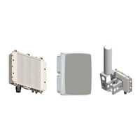
RDL-3000 family Broadband Wireless Radio Platforms
Brand: Redline
|
Category: Microphone system
|
Size: 4 MB
Table of Contents
-
-
-
-
-
System Menus33
-
-
RADIUS Setup56
-
-
Add68
-
Delete68
-
General78
-
Controls81
-
General82
-
System Users88
-
New User89
-
-
Advertisement
Redline RDL-3000 SC User Manual (138 pages)
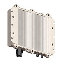
Broadband Wireless Radio Platform
Table of Contents
-
RF Ports17
-
Ground Lug18
-
Telnet (CLI)19
-
PMP Mode21
-
PTP Mode35
-
Main Menus38
-
Link LED41
-
Signal LED41
-
100 Led41
-
Fd Led42
-
System43
-
Ethernet44
-
General49
-
Wireless50
-
RADIUS Setup59
-
General77
-
General80
-
System Users86
-
Add User86
-
Delete User86
-
Command Set94
-
Apply94
-
Arp94
-
Chgver94
-
Clear94
-
Del95
-
Enable95
-
Freq95
-
Generate96
-
Get96
-
Load99
-
Logout100
-
New100
-
Ping100
-
Reboot100
-
Reset100
-
Save101
-
Script101
-
Set101
-
Show109
-
Snmpcommunity110
-
Snmptrap111
-
Upgrade111
-
User112
-
Whoami112

Redline RDL-3000 SC User Manual (143 pages)
Advanced Broadband Wireless Infrastructure Solutions
Brand: Redline
|
Category: Network Hardware
|
Size: 4 MB
Table of Contents
-
Ground Lug19
-
PMP Mode23
-
PTP Mode38
-
System Menu41
-
Link LED45
-
Ethernet47
-
Wireless52
-
RADIUS Setup61
-
System Users89
-
Command Set97
-
Chgver98
-
Enable99
-
Generate100
-
Load103
-
Logout104
-
Save105
Advertisement

Redline RDL-3000 SC Installation Manuallines (65 pages)
Radio Platform
Table of Contents
-
-
-
Features16
-
Overview16
-
Ground Lug20
-
Grounding20
-
RF Ports19
-
Telnet (CLI)19
-
-
-
-
-
Path Profile22
-
Materials24
-
-
-
-
-
Grounding26
-
Indoor Poe46
-
Web Browser48
-
Long Reset49
-
-
RF Ports36
-

Redline RDL-3000 SC Installation Manuallines (56 pages)
Universal Wireless Transport (UWT) System, Edge Wireless Terminal
Brand: Redline
|
Category: Touch terminals
|
Size: 4 MB
Table of Contents
-
-
-
-
-
Telnet (CLI)18
-
RF Ports15
-
Ground Lug16
-
-
Site Survey19
-
-
-
Path Profile20
-
Cable Length27
-
Isolation28
-
Power Source28
-
Cable Length26
-
-
-
-
-
Preparation30
-
Cable Ties41
-
-

Redline RDL-3000 SC Installation Manuallines (59 pages)
Ellipse TMA Sector Controller Multi-Sector System (UWT) System
Brand: Redline
|
Category: Controller
|
Size: 5 MB
Table of Contents
-
Ground Lug19
-
RF Ports19
-
RF in Ports20
-
Power Port21
-
Ground Lug21
-
RF out Ports21
-
RF Splitter28
-
Materials33
-
Site Survey34

Redline RDL-3000 SC Configuration Instructions (9 pages)
TV WHITE SPACES CONFIGURING TO COMMUNICATE WITH FCC TVWS DATABASE
Brand: Redline
|
Category: Accessories
|
Size: 2 MB