
Related Manuals for YASKAWA SGDH


Summary of Contents for YASKAWA SGDH
- Page 1 YASKAWA Series SGM□H/SGDH USER'S MANUAL SGMAH/SGMPH/SGMGH/SGMSH/SGMDH/SGMUH Servomotors SGDH SERVOPACK YASKAWA MANUAL NO. SIEPS80000005C...
- Page 2 Copyright 2003 YASKAWA ELECTRIC CORPORATION All rights reserved. No part of this publication may be reproduced, stored in a retrieval system, or transmitted, in any form, or by any means, mechanical, electronic, photocopying, recording, or otherwise, without the prior written permission of Yaskawa. No patent liability is assumed with respect to the use of the information contained herein.
- Page 3 • Parameter number = Numbers that the user inputs toward the SERVOPACK. Indication of Reverse Signals In this manual, the names of reverse signals (ones that are valid when low) are written with a forward slash (/) before the signal name, as shown in the following example: •...
- Page 4 • Indicates important information that should be memorized, including precautions such as alarm dis- IMPORTANT plays to avoid damaging the devices. • Indicates supplemental information. INFO • Indicates application examples. EXAMPLE • Indicates definitions of difficult terms or terms that have not been previously explained in this man- TERMS ual.
- Page 5 Digital Operator Operation Manual device). Σ-II Series SERVOPACKs SIE-S800-35 Describes the using and the operating methods on soft- Personal Computer Monitoring Software ware that changes the local personal computer into the monitor equipment for the Σ-II Series servomotor. Operation Manual Σ-II Series SGDH...
- Page 6 Safety Information The following conventions are used to indicate precautions in this manual. Failure to heed precautions provided in this manual can result in serious or possibly even fatal injury or damage to the products or to related equipment and systems.
- Page 7 Pn205 in the SERVOPACK to be sure that it is correct. If Fn013 is executed when an incorrect value is set in Pn205, an incorrect value will be set in the encoder. The alarm will disappear even if an incorrect value is set, but incorrect positions will be detected, resulting in a dangerous situation where the machine will move to unexpected positions.
- Page 8 • Do not store or install the product in the following places. • Locations subject to direct sunlight. • Locations subject to temperatures outside the range specified in the storage or installation temperature conditions. • Locations subject to humidity outside the range specified in the storage or installation humidity conditions.
- Page 9 Failure to observe this caution may result in injury. • Do not cover the inlet or outlet parts and prevent any foreign objects from entering the product. Failure to observe this caution may cause internal elements to deteriorate resulting in malfunction or fire.
- Page 10 The maximum length is 3 m (118.11 in) for reference input lines and is 20 m (787.40 in) for PG feedback lines. • Do not touch the power terminals for five minutes after turning power OFF because high voltage may still remain in the SERVOPACK.
- Page 11 Fn003. • When using the servomotor for a vertical axis, install the safety devices to prevent workpieces to fall off due to occurrence of alarm or overtravel. Set the servomotor so that it will stop in the zero clamp state at occurrence of overtravel.
- Page 12 When this manual is revised, the manual code is updated and the new manual is published as a next edition. • If the manual must be ordered due to loss or damage, inform your nearest Yaskawa representative or one of the offices listed on the back of this manual.
-
Page 13: Table Of Contents
Safety Information - - - - - - - - - - - - - - - - - - - - - - - - - - - - - - - - - - - - - -... -
Page 14: Table Of Contents
3.8.4 Impact Resistance - - - - - - - - - - - - - - - - - - - - - - - - - - - - - - - - - - - - 3-45... - Page 15 With Brakes- - - - - - - - - - - - - - - - - - - - - - - - - - - - - - - - - - - - - 3-122...
- Page 16 With Brakes - - - - - - - - - - - - - - - - - - - - - - - - - - - - - - - - - - - - 3-154...
- Page 17 Model - - - - - - - - - - - - - - - - - - - - - - - - - - - - - - - - - - - - - - 4-24...
- Page 18 Configurations - - - - - - - - - - - - - - - - - - - - - - - - - - - - - - - - - - - - - - -...
- Page 19 5.3.2 Single-phase 100 V - - - - - - - - - - - - - - - - - - - - - - - - - - - - - - - - - - - 5-46...
- Page 20 6.4 Others- - - - - - - - - - - - - - - - - - - - - - - - - - - - - - - - - - - - - - 6-19...
- Page 21 7.3.1 Setting Parameters - - - - - - - - - - - - - - - - - - - - - - - - - - - - - - - - - - - - 7-19...
- Page 22 8.6 Operating Using Position Control - - - - - - - - - - - - - - - - - - - 8-48 8.6.1 Setting Parameters - - - - - - - - - - - - - - - - - - - - - - - - - - - - - - - - - - - 8-48 8.6.2 Setting the Electronic Gear - - - - - - - - - - - - - - - - - - - - - - - - - - - - - - 8-50...
- Page 23 Module MC20- - - - - - - - - - - - - - - - - - - - - - - - - - - - - - - - - - - - - - 11-18...
- Page 24 11.3.1 Utility Functions List - - - - - - - - - - - - - - - - - - - - - - - - - - - - - - - - - 11-26 11.3.2 List of Parameters - - - - - - - - - - - - - - - - - - - - - - - - - - - - - - - - - - 11-27 11.3.3 Monitor Modes - - - - - - - - - - - - - - - - - - - - - - - - - - - - - - - - - - - - - 11-43...
-
Page 25: Checking Products - - - - - - - - - - - - - - - - - - - - - - - - - - - - - -
1.1.3... - Page 26 Check the overall appearance, and check for damage or scratches that may have occurred during shipping. If any of the above items are faulty or incorrect, contact your Yaskawa representative or the dealer from whom you purchased the products. 1.1.2 Servomotors SGMAH and SGMPH...
- Page 27 1.1 Checking Products 1.1.3 SERVOPACKs SGDH for 30 W to 5.0 kW SGDH for 6.0 kW to 15.0 kW SERVOPACK SERVOPACK MODEL SGDH-30AE model AC-INPUT AC-OUTPUT VOLTS 200-230 VOLTS 0-230 Applicable 60/60 PHASE motor Applicable PHASE AMPS 24.8 capacity power supply AMPS 18.6 KU (MP) 3.0 (4.0) Serial 412808-15-1 number YASKAWA ELECTRIC MADE IN JAPAN...
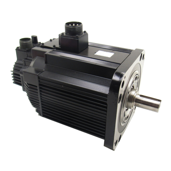
- Page 28 1 Outline 1.2.1 Servomotors 1.2 Product Part Names 1.2.1 Servomotors (1) SGMAH and SGMPH Without Gears and Brakes Servomotor connector Encoder connector Servomotor Encoder main circuit cable cable Nameplate Flange Output Encoder shaft (Detecting section) (2) SGMGH/SGMSH/SGMDH/SGMUH Without Gears and Brakes Servomotor connector Encoder connector Nameplate Flange Encoder (Detecting section)
- Page 29 Control power supply terminals Used for reference input signals and Used for control power supply input. sequence I/O signals. Refer to 6.1 Wiring Main Circuit. Refer to 6.3 Examples of I/O Signal Connections. Regenerative resistor connecting terminals Nameplate (side view) Used to connect external regenerative resistors. Indicates the SERVOPACK model and ratings. Refer to 6.5 Connecting Regenerative Resistors. Refer to 1.1.3 SERVOPACKs. Servomotor terminals Connects to the servomotor power line. Refer to 6.1 Wiring Main Circuit. CN2 Encoder connector Connects to the encoder in the servomotor. Refer to 6.2 Wiring Encoders. Ground terminal Be sure to connect to protect against electrical shock. Refer to 6.1 Wiring Main Circuit. Connecting terminal of DC Reactor INFO For connecting a reactor, refer to 6.4.8 DC Reactor for Harmonic Suppression.
- Page 30 Regenerative resistor ∗ connecting terminals: B1, B2 * Control circuit terminal and regenerative resistor connecting terminals differ the position of the termi- nal block by the SERVOPACK model. Refer to Chapter 4 SERVOPACK Specifications and Dimensional Drawings for details. SERVOPACK Model...
- Page 31 1.3 Examples of Servo System Configurations 1.3 Examples of Servo System Configurations This section describes examples of basic servo system configuration. 1.3.1 Single-phase, 100 V, 200 V and 220 V Main Circuit Power supply ∗1 For connecting a DC reactor, refer to 6.4.8 DC Reactor Single-phase 100/200 VAC for Harmonic Suppression. R T ∗2 SGDH-08AE-S SERVOPACK for SGMAH-08A and SGMPH- Molded-case 08A servomotors and SGDH-15AE-S SERVOPACK for ...
- Page 32 1 Outline 1.3.2 Three-phase, 200 V Main Circuit 1.3.2 Three-phase, 200 V Main Circuit ∗1 Power supply The main circuit positive-side terminal is only available Three-phase 200 VAC to use at three-phase 200 VAC, 6 kW SERVOPACK. R S T Do not use 1 or 2. ∗2 Be sure to disconnect the lead between B2 and Molded-case B3, before connecting an external regenerative circuit breaker (MCCB) registor to the SERVOPACK. ∗3 Protects the power supply For connecting a DC reactor, refer to 6.4.8 DC Reactor line by shutting the for Harmonic Suppression. circuit OFF when overcurrent is detected. (Refer to 5.8.9.) Noise filter Used to eliminate external noise from the ...
- Page 33 1.3 Examples of Servo System Configurations 1.3.3 Three-phase, 400 V Main Circuit Power supply Three-phase 400 VAC R S T Molded-case circuit breaker (MCCB) ∗1 Use a 24 VDC power supply. (Must be prepared by the user.) Protects the power supply ∗2 Be sure to disconnect the lead between B2 and B3, before line by shutting the circuit OFF when connecting an external regenerative registor to the overcurrent is SERVOPACK. detected. ∗3 For connecting a DC reactor, refer to 6.4.8 DC Reactor for (Refer to 5.8.9.) Harmonic Suppression. Noise filter Used to eliminate external noise from the power line. (Refer to 5.8.10.) SGDH- DE ...
- Page 34 • SGMSH • SGMDH ∗3 • SGMUH * 1. Underwriters Laboratories Inc. * 2. Canadian Standards Association. * 3. SGMUH servomotors of 4.0 kW do not conform to these standards. 1.4.2 CE Marking EMC Directive Low Voltage Model Certifications Directive...
-
Page 35: Servomotor Model Designations - - - - - - - - - - - - - - - - - - - -
DC Reactors - - - - - - - - - - - - - - - - - - - - - - - - - - - - - - - - - - - - -... - Page 36 2 Selections 2.1.1 Model SGMAH (3000 min 2.1 Servomotor Model Designations This section explains how to check the servomotor model and ratings. The alphanumeric codes after SGM H indicate the specifications. 2.1.1 Model SGMAH (3000 min (1) Without Gears 1st + ...
- Page 37 2.1 Servomotor Model Designations (2) With Gears 1st + 5th digits digits digits digits digits digits digits digits SGMAH − 01 A A H 1 2 B 9th digit: Brake 1st + 2nd digits: 3rd digit: Rated Output Voltage Code Specifications (kW) A:200V,B:100V,D:400V Without brake Code Rated Output With 90-VDC brake −...
- Page 38 2.1.2 Model SGMPH (3000 min 2.1.2 Model SGMPH (3000 min (1) Without Gears 1st + 5th digits digits digits digits digits digits SGMPH − 02 A A A 2 1 1st + 2nd digits: 3rd digit: 7th digit: Brake and Oil Seal Rated Output Voltage (kW) Code Specifications A:200V,B:100V,D:400V Without options Code ...
- Page 39 2.1 Servomotor Model Designations (2) With Gears 1st + 5th digits digits digits digits digits digits digits digits SGMPH − 01 A A H 1 2 B 1st + 2nd digit: 3rd digit: 9th digit: Brake Rated Output Voltage Code Specifications A:200V,B:100V,D:400V Without brake Code Rated Output − With 90-VDC brake With 24-VDC brake −...
- Page 40 2 Selections 2.1.3 Model SGMGH (1500 min 2.1.3 Model SGMGH (1500 min (1) Without Gears 1st + 5th digits digits digits digits digits digits SGMGH −13 A C A 2 1 7th digit: Brake and Oil Seal 1st + 2nd digits: 3rd digit: Voltage Rated Output (kW) A:200V,D:400V Code Specifications Without options Code Rated Output With 90-VDC brake 0.45...
- Page 41 − − − − − : Available 6th digit: 1st + 2nd + 3rd digits: Code of the Rated Output and Voltage 7th digit: Gear Ratio Gear Type Code 05A 05D 09A 09D 13A 13D 20A 20D 30A 30D 44A 44D 55A 55D 75A Specifications Code − − 1/11 (Stan- 1/21 dard) 1/29 : Available 6th digit: 1st + 2nd + 3rd digits: Code of the Rated Output and Voltage 7th digit: Gear Ratio...
- Page 42 2.1.4 Model SGMGH (1000 min 2.1.4 Model SGMGH (1000 min (1) Without Gears 1st + 5th digits digits digits digits digits digits SGMGH − 12 A C B 2 1 1st + 2nd digits: 3rd digit: Rated Output Voltage 7th digit: Brake and Oil Seal (kW) A: 200V Code Specifications Code Rated Output Without options...
- Page 43 1/29 − − − − 1/45 − − − − : Available 6th digit: 7th digit: Gear Ratio 1st + 2nd + 3rd digits: Code of the Rated Output and Voltage Gear Type Code 03A 06A 09A 12A 20A 30A 40A Specifications Code − 1/11 (Stan- 1/21 dard) 1/29 : Available 6th digit: 7th digit: Gear Ratio 1st + 2nd + 3rd digits: Code of the Rated Output and Voltage Gear Type Code Specifications...
- Page 44 2.1.5 Model SGMSH (3000 min 2.1.5 Model SGMSH (3000 min (1) Without Gears 1st + 5th digits digits digits digits digits digits SGMSH − 10 A C A 2 1 1st + 2nd digits: 3rd digit: Rated Output Voltage 7th digit: Brake and Oil Seal (kW) A:200V,D:400V Code Specifications Code Rated Output Without options...
- Page 45 2.1 Servomotor Model Designations (2) With Gears 1st + 5th digits digits digits digits digits digits digits digits SGMSH − 10 A A L 1 4 B 9th digit: Brake 1st + 2nd digits: 3rd digit: Code Specifications Rated Output Voltage A:200V,D:400V (kW) Without brake Code Rated Output With 90-VDC brake With 24-VDC brake 8th digit: Shaft End...
- Page 46 2.1.6 Model SGMDH (2000 min 2.1.6 Model SGMDH (2000 min • SGMDH servomotors are provided with 90-VDC brakes as standard. (The seventh digit: B) • Servomotors with backlash gears are not available for the model SGMDH. 1st + 5th digits digits...
- Page 47 2.1 Servomotor Model Designations 2.1.7 Model SGMUH (6000 min • Servomotors with backlash gears are not available for the model SGMUH. 1st + 5th digits digits digits digits digits digits SGMUH − 10 D C A 2 1 3rd digit: 1st + 2nd digits: Rated Output Voltage 7th digit: Brake and Oil Seal...
- Page 48 2.2 Selecting Servomotors 2.2.1 Support Tool for the Capacity Selection of the AC Servomotors For easy selection of the capacity of the AC servomotors, a CD-ROM is available as a support tool. • CD-ROM: Programming for the capacity selection on AC servomotor...
- Page 49 2.3 SERVOPACK Model Designations 2.3 SERVOPACK Model Designations Select the SERVOPACK according to the applied servomotor. 1st + 5th digits digits digits digits SGDH - 5th digit: Mounting Method 1st + 2nd digits: Rated Output of Code Specificatioins Rated Output of Applicable Servomotor (kW) Applicable Servomotor (kW) − 0.03 to 15.0 Base-mounted Code Rated Output Code Rated Output Duct-ventilated 5.5 to 15.0 0.03 Rack-mounted 0.03 to 5.0...
- Page 50 4 models − − − (4.0 kW) 50DE Note: 1. =A: 200 V, B: 100 V, D: 400 V (Be sure to match the voltage ratio on the servomotor and the SERVOPACK.) 2. Servomotors with low-backlash gears are available. 2-16...
- Page 51 2.5 Selecting Cables 2.5 Selecting Cables 2.5.1 Cables for SGMAH and SGMPH Servomotors YASKAWA 200V SERVOPACK SGDH- MODE/SET DATA/ CHARGE POWER 2-17...
- Page 52 2 Selections 2.5.1 Cables for SGMAH and SGMPH Servomotors Refer- Name Length Type Specifications ence JZSP-CMP00-03 (9.84 ft) JZSP-CMP00-05 (16.4 ft) SERVOPACK Encoder 10 m Cable with connec- 5.4.1 JZSP-CMP00-10 tors at both ends (32.8 ft) 15 m JZSP-CMP00-15 (49.2 ft)
- Page 53 2.5 Selecting Cables Refer- Name Length Type Specifications ence Soldered SERVOPACK end 5.5.1 JZSP-CMP9-1 connector kit Soldered 5.4.3 5.4.5 Encoder end connector kit JZSP-CMP9-2 5.5.1 JZSP-CMP09-05 (16.4 ft) 10 m JZSP-CMP09-10 Encoder (32.8 ft) 20 m (65.6 ft) max. Cable 15 m JZSP-CMP09-15 (Cont’d) (49.2 ft) 20 m 5.5.1...
- Page 54 JZSP-CMM01-15 (49.2 ft) 750 W 20 m JZSP-CMM01-20 (65.6 ft) Note: When using the cable for the moving section such as robots, use a flexible type cable. For the safety precautions, see 5.7 I/O Signal Cables for CN1 Connector. 2-20...
- Page 55 JZSP-CMM11-15 (49.2 ft) 750 W 20 m JZSP-CMM11-20 (65.6 ft) Note: When using the cable for the moving section such as robots, use a flexible type cable. For the safety precautions, see 5.7 I/O Signal Cables for CN1 Connector. 2-21...
- Page 56 2 Selections 2.5.2 Cables for SGMGH/SGMSH/SGMDH/SGMUH Servomotors Servomotor Refer- Name Length Type Specifications Model ence SGMAH For standard 30 W to 750 W JZSP-CMM9-1 environment SGMPH connector kit 100 W to 750 W without SGMPH Servomotor brakes JZSP-CMM9-3 1.5 kW Main Circuit 5.2.2...
- Page 57 SERVOPACK end Encoder end 10 m JZSP-CMP02-10 (32.8 ft) 15 m JZSP-CMP02-15 (49.2 ft) 20 m JZSP-CMP02-20 (65.6 ft) Straight plug MS3106B20-29S* L-shaped plug 5.4.4 For standard environment MS3108B20-29S* 5.5.2 encoder end connector Cable clamp MS3057-12A* * Contact DDK Electronics, Inc. 2-23...
- Page 58 2 Selections 2.5.2 Cables for SGMGH/SGMSH/SGMDH/SGMUH Servomotors Refer- Name Length Type Specifications ence Straight plug JA06A-20-29S-J1-EB L-shaped plug JA08A-20-29S-J1-EB JL04-2022CKE (09) Cable diameter: For IP67 specification φ6.5 to φ9.5 mm 5.5.2 encoder end connector (φ0.26 to φ0.37 in) JL04-2022CKE (12)
- Page 59 Dimensional Drawings of Cables and Cables and Peripheral Devices. Connectors Note: When using the cable for the moving section such as robots, use a flexible type cable. For the safety precautions, see 5.7 I/O Signal Cables for CN1 Connector. 2-25...
- Page 60 2 Selections 2.6.1 Special Options 2.6 Selecting Peripheral Devices 2.6.1 Special Options Digital operator Connection cable Personal for digital operator computer YASKAWA 200V SERVOPACK Connection cable SGDH- for personal computer MODE/SET DATA/ CHARGE POWER Host controller I/O signal cable Analog monitor cable Battery for absolute encoder CN10 NS500 NS600 FC100 NS100 NS300 CN11 CN11 YASKAWA...
- Page 61 2.6 Selecting Peripheral Devices Refer- Name Length Type Specifications ence Terminal block and 0.5 m (1.64 ft) connection cable Connector terminal block 5.8.4 JUSP-TA50P converter unit I/O Signal JZSP-CKI01-1 (3.28 ft) Cables Loose wires at host controller end Cable with 5.7.1...
- Page 62 DeviceNet I/F 5.8.17 JUSP-NS300 Unit (NS300) ⑦ Application Module ∗ Fully-closed I/F 5.8.21 JUSP-FC100 Unit (FC100) PROFIBUS-DP 5.8.18 JUSP-NS500 I/F Unit (NS500) INDEXER Mod- 5.8.19 JUSP-NS600 ule (NS600) * For details, refer to the manuals of each application module. 2-28...
- Page 63 * 2. Cutoff characteristics (25 C): 300% five seconds min. and inrush current of 20ms. * 3. A preventive circuit for inrush current is not built in the 24 VDC control power supply. The protective circuit must be designed by the customer.
- Page 64 The SGDH SERVOPACK does not include a protective grounding circuit. Install a ground-fault protector IMPORTANT to protect the system against overload and short-circuit or protective grounding combined with the molded- case circuit breaker. 2.6.3 Noise Filters, Magnetic Contactors, Surge Suppressors and DC Reactors...
- Page 65 2.6 Selecting Peripheral Devices Note: 1. If some SERVOPACKs are wired at the same time, select the proper magnetic contactors accord- ing to the total capacity. 2. The following table shows the manufacturers of each device. Peripheral Device Manufacturer FN, FS type: Schaffner Electronic...
- Page 66 * 4. For the optional JUSP-RA19 Regenerative Resistor Unit. * 5. Be careful when connecting the power supply for 24 VDC brake to the local power supply. The local power supply cannot apply the overvoltage such as surge to the output side, and the output side may be damaged even if the voltage is applied.
- Page 67 3.8.4 Impact Resistance - - - - - - - - - - - - - - - - - - - - - - - - - - - - - - - - - - - - 3-45...
- Page 68 With Brakes - - - - - - - - - - - - - - - - - - - - - - - - - - - - - - - - - - - - - -...
- Page 69 ) Without Gears and Without Brakes - - - - - - - - - - - - - - - - - - - - - - - - - - - - - - - - - - - - 3-141 3.16.2 SGMSH Servomotors (3000 min...
- Page 70 PACK are at an armature winding temperature of 100°C (212°F). Other values quoted at 20°C (68°F). All values are typical. * 2. Rated torques are continuous allowable torque values at 40°C (104°F) with an 250 × 250 × 6 (mm) [10 × 10 × 0.24 (in.)] aluminum plate (heat sink) attached.
- Page 71 ×10 oz in s * These values are reference values. (3) Derating Rate for Servomotor With Oil Seal For a motor with oil seal, use the following derating rate because of the higher friction torque. Servomotor Model SGMAH- Derating Rate...
-
Page 72: Sgmah Servomotors With Standard Backlash Gears - - - - - - - - - - - -
SGMAH-08 2.39 (338) 75.2 0.32 Note: The holding brake is only used to hold the load and cannot be used to stop the servomotor. 3.1.2 SGMAH Servomotors With Standard Backlash Gears • Time Rating: Continuous • Thermal Class: B • Vibration Class: 15 µm or below •... - Page 73 3.1 Ratings and Specifications of SGMAH (3000 min Moment of Inertia J ×10 kg·m Servomotor Gear Output (x 10 oz·in·s Servomotor Rated Instanta- Model Torque/ Rated neous Max. Rated Rated Out- SGMAH- Effi- Torque Gear Peak Motor + ∗1 Speed...
- Page 74 (30019) (13.8) (4.25) * 1. Maximum motor speed is up to 4000 min at the shaft. * 2. Gear output torque is expressed using the following equation. (Gear output torque) = (servomotor output torque) × × (efficiency) gear ratio 3.1.3 SGMAH Servomotors With Low-backlash Gears •...
- Page 75 3.1 Ratings and Specifications of SGMAH (3000 min Moment of Inertia J ×10 Servomotor Gear Output kg·m (x 10 oz·in·s Servomotor Instanta- Rated Model Rated neous Max. Torque/Effi- Rated Rated Out- SGMAH- Torque Gear Peak Motor + ∗1 ∗2 Speed...
- Page 76 × (efficiency) gear ratio * 3. The instantaneous peak torque values indicated with ∗3 are limited by the gear, so use the following servomotor instantaneous peak torque. In this case, set torque limit parameters Pn402 and 403 for the SERVOPACK at 250%.
- Page 77 PACK are at an armature winding temperature of 100°C (212°F). Other values quoted at 20°C (66.2°F). All values are typical. * 2. Rated torques are continuous allowable torque values at 40°C (104°F) with an aluminum plate (heat sink) attached. Heat sink dimensions: SGMPH-01, 02, and 04: 250 ×...
- Page 78 ×10 oz in s * These values are reference values. (3) Derating Rate for Servomotor With Oil Seal For a motor with oil seal, use the following derating rate because of the higher friction torque. Servomotor Model SGMPH- Derating Rate...
-
Page 79: Sgmph Servomotors With Standard Backlash Gears - - - - - - - - - - -
1500 57.6 0.42 (675) Note: The holding brake is only used to hold the load and cannot be used to stop the servomotor. 3.2.2 SGMPH Servomotors With Standard Backlash Gears • Time Rating: Continuous • Thermal Class: B • Vibration Class: 15 µm or below •... - Page 80 80.1/80 5.33 1/21 (11342/80) (38232) (755) (18.4) 0.800 126/80 4.82 1/33 (17842/80) (60180) (683) (11.3) * 1. Maximum motor speed is up to 4000 min at the shaft. * 2. Gear output torque is expressed using the following equation. 3-14...
- Page 81 3.2 Ratings and Specifications of SGMPH (3000min * 3. (Gear output torque) = (servomotor output torque) × × (efficiency) gear ratio 3.2.3 SGMPH Servomotors With Low-backlash Gears • Time Rating: Continuous • Thermal Class: B • Vibration Class: 15 µm or below •...
- Page 82 × (efficiency) gear ratio * 3. The instantaneous peak torque values indicated with ∗3 are limited by the gear, so use the following servomotor instantaneous peak torque. In this case, set torque limit parameters Pn402 and 403 for the SERVOPACK at 250%.
-
Page 83: 3.3 Ratings And Specifications Of Sgmgh (1500Min
• Ambient Humidity: 20% to 80% (no condensation) • Drive Method: Direct drive (a) 200-V Class Voltage 200 V Servomotor Model SGMGH- 05A A 09A A 13A A 20A A 30A A 44A A 55A A 75A A 1AA A 1EA A ∗1 0.45 0.85 Rated Output 2.84... -
Page 84: 3.3.1 Sgmgh Servomotors (1500Min
3.3.1 SGMGH Servomotors (1500min ) Without Gears (b) 400-V Class Voltage 400 V Servomotor Model 05D A 09D A 13D A 20D A 30D A 44D A 55D A 75D A 1AD A 1ED A SGMGH- Rated 0.45 0.85 ∗1 Output 2.84... - Page 85 3.3 Ratings and Specifications of SGMGH (1500min (2) Holding Brake Moment of Inertia The moment of inertia of the servomotor with holding brake is expressed using the following equation. (The moment of inertia of the servomotor with holding brake) =...
- Page 86 SGMGH-75 7500 23.5 24.5 0.98 (643) 84.3 SGMGH-1A 11000 32.0 18.0 1.33 (746) 114.6 SGMGH-1E 15000 35.0 16.4 1.46 (1014) Note: The holding brake is only used to hold the load and cannot be used to stop the servomotor. 3-20...
-
Page 87: With Standard Backlash Gears - -
• Gear Lubricating Method: Type 4095 to 4115: Grease ∗ Type 4130 to 4190: Oil * For oil lubrication, the motor should be mounted horizontal to the shaft. Contact your Yaskawa representative about lubrication for angle mounting. Moment of Inertia J Servomotor Gear Output ×10... -
Page 88: 3.3.2 Sgmgh Servomotors (1500Min
3 Specifications and Dimensional Drawings 3.3.2 SGMGH Servomotors (1500min ) With Standard Backlash Gears Moment of Inertia J ×10 Servomotor Gear Output kg·m (×10 lb·in·s Instanta- Servomotor Rated Model neous Rated Rated Rated Max. Torque/ Out- Peak SGMGH- Torque Gear... -
Page 89: With Low-Backlash Gears - - - - -
(211) Note: 1. For the shaft center allowable radial load, refer to the servomotor dimensional drawing. 2. Output torque and motor speed produce the following trends in efficiency. Values in the table are at the rated motor speed. 3. 15-kW servomotors do not equipped with gears. -
Page 90: 3.3.3 Sgmgh Servomotors (1500Min
3 Specifications and Dimensional Drawings 3.3.3 SGMGH Servomotors (1500min ) With Low-backlash Gears Moment of Inertia J ×10 Servomotor Gear Output kg·m (×10 lb·in·s Instanta- Servomotor Rated neous Model Rated Max. Torque/ Rated Rated Out- Peak SGMGH- Torque Gear Motor + ∗1... - Page 91 Note: For the shaft center allowable radial load, refer to the servomotor dimensional drawing. * 1. The maximum input motor speed of the gears is 4000 min * 2. Output torque and motor speed produce the following trends in efficiency. Values in the table are at the rated motor speed.
-
Page 92: 3.4 Ratings And Specifications Of Sgmgh (1000Min
Note: These characteristics are values with the following iron plate (heat sinks) attached for cooling. SGMGH-03, 06, and 09: 400 × 400 × 20 (mm) [15.75 × 15.75 × 0.79 (in)] SGMGH-12, 20, 30, 40 and 55: 550 × 550 × 30 (mm) [21.65 × 21.65 × 1.18 (in)] 3-26... - Page 93 3.4 Ratings and Specifications of SGMGH (1000min (2) Holding Brake Moment of Inertia The moment of inertia of the servomotor with holding brake is expressed using the following equation. (The moment of inertia of the servomotor with holding brake) =...
-
Page 94: 3.4.1 Sgmgh Servomotors (1000Min
SGMGH-30 3000 18.5 31.1 0.77 (381) 72.6 SGMGH-40 4000 23.5 22.8 1.05 (643) 72.6 SGMGH-55 5500 23.5 22.8 1.05 (643) Note: The holding brake is only used to hold the load and cannot be used to stop the servomotor. 3-28... -
Page 95: With Standard Backlash Gears -
Type 4095 to 4115: Grease • Gear Mechanism: Planetary gear mechanism ∗ Type 4130 to 4190: Oil * For oil lubrication, the motor should be mounted horizontal to the shaft. Contact your Yaskawa representative about lubrication for angle mounting. Moment of Inertia J ×10... -
Page 96: 3.4.2 Sgmgh Servomotors (1000Min
55A B C6 (466) (7815/80) (20357/80) (181) (69.9) 1220/80 3176/80 91.0 1/29 55A B 76 (10798/80) (28111/80) (191) (80.5) Note: Output torque and motor speed produce the following trends in efficiency. Values in the table are at the rated motor speed. 3-30... -
Page 97: 3.4.3 Sgmgh Servomotors (1000 Min
• Ambient Humidity: 20% to 80% (no condensation) • Excitation: Permanent magnet • Drive Method: Direct drive • Mounting: Flange method (can be mounted in any direction) • Gear Lubricating Method: Grease • Gear Mechanism: Planetary gear mechanism • Backlash: 0.05° (3 min) at the gear output shaft •... - Page 98 (251) 204/80 459/80 80.0 12.5 30A BL24 (1806/80) (4063/80) (70.8) (11.1) Note: Output torque and motor speed produce the following trends in efficiency. Values in the table are at the rated motor speed. Efficiency Efficiency Output torque Output torque 3-32...
-
Page 99: 3.5 Ratings And Specifications Of Sgmsh (3000Min
200 V Servomotors: 1500 VAC for one minute • Insulation Resistance: 500 VDC, 10 MΩ min. 400 V Servomotors: 1800 VAC for one minute • Ambient Temperature: 0 to 40°C (32 to 104°F) • Enclosure: Totally enclosed, IP67 self-cooled • Excitation: Permanent magnet (except for shaft opening) •... -
Page 100: 3.5.1 Sgmsh Servomotors (3000Min
(2) Holding Brake Moment of Inertia The moment of inertia of the servomotor with holding brake is expressed using the following equation. (The moment of inertia of the servomotor with holding brake) = (rotor moment of inertia) + (brake moment of inertia) Servomotor... - Page 101 3.5 Ratings and Specifications of SGMSH (3000min (3) Torque-motor Speed Characteristics SGMSH-20A A, -20D A SGMSH-30A A, -30D A SGMSH-10A A, -10D A SGMSH-15A A, -15D A 5000 5000 5000 5000 4000 4000 4000 4000 3000 3000 3000 3000 Motor...
-
Page 102: 3.5.2 Sgmsh Servomotors (3000Min
5000 9.85 58.7 0.41 (177) Note: The holding brake is only used to hold the load and cannot be used to stop the servomotor. 3.5.2 SGMSH Servomotors (3000min ) With Low-backlash Gears • Time Rating: Continuous • Thermal Class: F •... - Page 103 3.5 Ratings and Specifications of SGMSH (3000min Moment of Inertia J ×10 Servomotor Gear Output kg·m (×10 lb·in·s Servomotor Instanta- Rated Model neous Rated Max. Rated Torque/Effi- Rated Out- Peak SGMSH- Torque Gear Motor + ∗1 Speed ∗2 Speed Torque/...
- Page 104 Note: For the shaft center allowable radial load, refer to the servomotor dimensional drawing. * 1. The maximum input motor speed of the gears is 4000 min * 2. Output torque and motor speed produce the following trends in efficiency. Values in the table are at the rated motor speed.
-
Page 105: 3.6 Ratings And Specifications Of Sgmdh (2000Min
SERVOPACK are at an armature winding temperature of 20°C (68°F). * 2. These values reference values. Note: These characteristics are values with the following iron plates (heat sinks) attached for cooling. 650 × 650 × 35 (mm) [25.59 × 25.59 × 1.38 (in)]... -
Page 106: 3.6.1 Sgmdh Servomotors (2000Min
2200 16.0 36.0 0.67 (260) 29.4 SGMDH-32 3200 16.0 36.0 0.67 24VDC (260) 29.4 SGMDH-40 4000 16.0 36.0 0.67 (260) Note: The holding brake is only used to hold the load and cannot be used to stop the servomotor. 3-40... -
Page 107: 3.7 Ratings And Specifications Of Sgmuh (6000Min
* 2. These values are reference values. * 3. The values in the parentheses are those for motors with holding brakes. Note: These characteristics are values with the following aluminum plates (heat sinks) attached for cool- ing. SGMUH-10 and 15: 300 × 300 × 12 (mm) [11.81 × 11.81 × 0.47 (in)] SGMUH-30 and 40: 400 ×... -
Page 108: 3.7.1 Sgmuh Servomotors (6000Min
(2) Holding Brake Moment of Inertia The moment of inertia of the servomotor with holding brake is expressed using the following equation. (The moment of inertia of the servomotor with holding brake) = (rotor moment of inertia) + (brake moment of inertia) Servomotor... -
Page 109: Mechanical Specifications Of Servomotors - - - - - - - - - - - -
3.8.1 Precautions on Servomotor Installation Servomotors can be installed either horizontally or vertically. The service life of the servomotor will be shortened or unexpected problems will occur if the servomotor is installed incorrectly or in an inappropriate location. Always observe the following installation instructions. - Page 110 Make sure there are no bends or tension on the power lines. Cable Stress Especially be careful to wire signal line cables so that they are not subject to stress because the core wires are very thin at only 0.2 to 0.3 mm (0.0079 to 0.012 in).
- Page 111 15 µm or below. The vibration class Vibration Class TERMS A vibration class of 15 µm or below indicates a total vibration amplitude of 15 µm maximum on the servomotor during rated rotation. 3-45...
- Page 112 Rated torque Rated torque (2) Noise Data The following noise data for a servomotor with a gear is for reference only and may slightly vary with the capac- ity and gear ratio of the servomotor. Measurement Conditions: • Scale A: 50 cm (19.7 in) •...
- Page 113 3.9 Terms and Data for Servomotors With Gears (3) Efficiency The output torque and motor speed produce the following trends in efficiency. The values in the tables, Ratings and Specifications of SGM H Servomotors with Gears, are at the rated motor torque and rated motor speed...
- Page 114 3 Specifications and Dimensional Drawings 3.10 Servomotor Dimensional Drawings Dimensional drawings for the SGM H servomotors are broadly grouped using the following categories: With or without gears or brakes. Refer- Series Motor Capacity Groups of Servomotor Dimensional Drawings ence 3.11.1...
- Page 115 4) are as shown below. SGMAH-A3, A5, and 01: L-dimension +12 mm (0.47 in), LL-dimension +12 mm (0.47 in) 2. The working point of the SGMAH servomotor radial load is at the position of minus 5 mm from the shaft end. 3-49...
- Page 116 – 0.008 – 0.0003 0.315 – 0.009 – 0.0004 (2) 200 W, 400 W, 750 W ∗ Units: mm (in) Model SGMAH- 126.5 96.5 (4.98) (3.80) (2.48) (1.18) (0.12) (0.24) (2.76) (0.22) 04A A21 154.5...
- Page 117 SGMAH-02 and 04: L-dimension + 8.2 mm (0.32 in), LL-dimension +8.2 mm (0.32 in). SGMAH-08: L-dimension + 0 mm, LL-dimension +0 mm. 2. The working point of the SGMAH servomotor radial load is at the position of minus 5 mm from the shaft end. • Dimensional Tolerances...
- Page 118 SGMAH-03: L-dimension + 8.2 mm (0.32 in), LL-dimension +8.2 mm (0.32 in). SGMAH-07: L-dimension + 0 mm, LL-dimension +0 mm. 2. The working point of the SGMAH servomotor radial load is at the position of minus 5 mm from the shaft end. 3-52...
- Page 119 3.11 Dimensional Drawings of SGMAH Servomotors (3000 min • Dimensional Tolerances Units: mm (in) Shaft-end Dimensions Flange Face Dimensions Model SGMAH- 03D A21 0.5512 1.9685 03D A41 – 0.011 – 0.00043 –...
- Page 120 4) are as shown below. SGMAH-A3, A5, and 01: L-dimension +12 mm (0.47 in), LL-dimension +12 mm (0.17 in). 2. The working point of the SGMAH servomotor radial load is at the position of minus 5 mm from the shaft end. • Dimensional Tolerances...
- Page 121 SGMAH-02 and 04: L-dimension +8.2 mm (0.32 in), LL-dimension +8.2 mm (0.32 in) SGMAH-08: L-dimension + 0 mm, LL-dimension +0 mm 2. The working point of the SGMAH servomotor radial load is at the position of minus 5 mm from the shaft end. • Dimensional Tolerances...
- Page 122 SGMAH-03: L-dimension + 8.2 mm (0.32 in), LL-dimension +8.2 mm (0.32 in) SGMAH-07: L-dimension + 0 mm, LL-dimension +0 mm 2. The working point of the SGMAH servomotor radial load is at the position of minus 5 mm from the shaft end. 3-56...
- Page 123 3.11 Dimensional Drawings of SGMAH Servomotors (3000 min • Dimensional Tolerances Units: mm (in) Shaft-end Dimensions Flange Face Dimensions Model SGMAH- 03D A2 0.5512 1.9685 03D A4 – 0.011 – 0.00043 –...
- Page 124 4) are as shown below. SGMAH-A3, A5, and 01: L-dimension +12 mm (0.47 in), LL-dimension +12 mm (0.47 in) 2. The working point of the SGMAH servomotor radial load is at the position of minus 5 mm from the shaft end. 3-58...
- Page 125 3.11 Dimensional Drawings of SGMAH Servomotors (3000 min • Dimensional Tolerances Units: mm (in) Flange Face Dimensions Shaft-end Dimensions Model SGMAH- AJ1 1 0.55 2.20 – 0.030 – 0.0012 – 0.018 –...
- Page 126 3 Specifications and Dimensional Drawings 3.11.3 SGMAH Servomotors (3000 min ) With Standard Backlash Gears (2) 200 W, 400 W, 750 W 300 (11.81)±30 (1.18) Encoder plug Encoder cable φ7 (φ0.28) Shaft End UL20276 (35) (1.38) Motor cable Motor plug φ7 (φ0.28)
- Page 127 SGMAH-02 and 04: L-dimension + 8.2 mm (0.32 in), LL-dimension +8.2 mm (0.32 in) SGMAH-08: L-dimension + 0 mm, LL-dimension +0 mm 2. The working point of the SGMAH servomotor radial load is at the position of minus 5 mm from the shaft end. • Dimensional Tolerances...
- Page 128 3 Specifications and Dimensional Drawings 3.11.3 SGMAH Servomotors (3000 min ) With Standard Backlash Gears Units: mm (in) Flange Face Dimensions Shaft-end Dimensions Model SGMAH- 3.94 0.98 AJ3 1 – 0.035 –...
- Page 129 SGMAH-03: L-dimension + 8.2 mm (0.32 in), LL-dimension +8.2 mm (0.32 in) SGMAH-07: L-dimension + 0 mm, LL-dimension +0 mm 2. The working point of the SGMAH servomotor radial load is at the position of minus 5 mm from the shaft end. • Dimensional Tolerances...
- Page 130 3 Specifications and Dimensional Drawings 3.11.4 SGMAH Servomotors (3000 min ) With Standard Backlash Gears and Brakes 3.11.4 SGMAH Servomotors (3000 min ) With Standard Backlash Gears and Brakes (1) 30 W, 50 W, 100 W Encoder cable φ6 (φ0.24) 300 (11.81)±30(1.18)
- Page 131 4) are as shown below. SGMAH-03, A5, and 01: L-dimension +12 mm (0.47 in), LL-dimension +12 mm (0.47 in) 2. The working point of the SGMAH servomotor radial load is at the position of minus 5 mm from the shaft end. • Dimensional Tolerances...
- Page 132 3 Specifications and Dimensional Drawings 3.11.4 SGMAH Servomotors (3000 min ) With Standard Backlash Gears and Brakes Units: mm (in) Flange Face Dimensions Shaft-end Dimensions Model SGMAH- 2.56 0.63 – 0.030 –...
- Page 133 SGMAH-02 and 04: L-dimension + 8.2 mm (0.32 in), LL-dimension +8.2 mm (0.32 in) SGMAH-08: L-dimension + 0 mm, LL-dimension +0 mm 2. The working point of the SGMAH servomotor radial load is at the position of minus 5 mm from the shaft end. 3-67...
- Page 134 3 Specifications and Dimensional Drawings 3.11.4 SGMAH Servomotors (3000 min ) With Standard Backlash Gears and Brakes • Dimensional Tolerances Units: mm (in) Flange Face Dimensions Shaft-end Dimensions Model SGMAH- 3.35 0.79 ...
- Page 135 3.11 Dimensional Drawings of SGMAH Servomotors (3000 min (3) 300 W, 650 W Encoder plug 300(11.81)±30(1.18) Encoder cable φ6 (φ0.24) Shaft End UL20276 Motor cable φ7 (φ0.28) (35) Motor plug (1.38) (0.0024) 0.04 300(11.81)±30(1.81) 0.06 (0.0016) φ0.05 26.5 (1.04) (φ0.0020) 13 (0.51)
- Page 136 SGMAH-03: L-dimension + 8.2 mm (0.32 in), LL-dimension +8.2 mm (0.32 in) SGMAH-07: L-dimension + 0 mm, LL-dimension +0 mm 2. The working point of the SGMAH servomotor radial load is at the position of minus 5 mm from the shaft end. • Dimensional Tolerances...
- Page 137 3.11 Dimensional Drawings of SGMAH Servomotors (3000 min 3.11.5 SGMAH Servomotors (3000 min ) With Low-backlash Gears (1) 30 W, 50 W, 100 W 300(11.81)±30(1.18) Encoder cable φ6 (φ0.24) Encoder plug UL20276 Motor cable (35) (1.38) Shaft End φ7(φ0.28) Motor plug 300(11.81)±30(1.18)
- Page 138 4) are as shown below. SGMAH-03, A5, and 01: L-dimension +12 mm (0.47 in), LL-dimension +12 mm (0.47 in) 2. The working point of the SGMAH servomotor radial load is at the position of minus 5 mm from the shaft end. 3-72...
- Page 139 3.11 Dimensional Drawings of SGMAH Servomotors (3000 min • Dimensional Tolerances Units: mm (in) Flange Face Dimensions Shaft-end Dimensions Model SGMAH- AH1 1 2.20 0.55 – 0.030 – 0.0012 – 0.018 –...
- Page 140 3 Specifications and Dimensional Drawings 3.11.5 SGMAH Servomotors (3000 min ) With Low-backlash Gears (2) 200 W, 400 W, 750 W 300(11.81)±30(1.18) Encoder plug Encoder cable φ7 (φ0.28) Shaft End UL20276 (35)(1.38) Motor cable Motor plug φ7(φ0.28) 0.04 (0.0024) 300±30 (0.0016)
- Page 141 SGMAH-02 and 04: L-dimension + 8.2 mm (0.32 in), LL-dimension +8.2 mm (0.32 in) SGMAH-08: L-dimension + 0 mm, LL-dimension +0 mm 2. The working point of the SGMAH servomotor radial load is at the position of minus 5 mm from the shaft end. 3-75...
- Page 142 3 Specifications and Dimensional Drawings 3.11.5 SGMAH Servomotors (3000 min ) With Low-backlash Gears • Dimensional Tolerances Units: mm (in) Flange Face Dimensions Shaft-end Dimensions Model SGMAH- AH1 1 3.35 0.79 –...
- Page 143 SGMAH-03: L-dimension + 8.2 mm (0.32 in), LL-dimension +8.2 mm (0.32 in) SGMAH-07: L-dimension + 0 mm, LL-dimension +0 mm 2. The working point of the SGMAH servomotor radial load is at the position of minus 5 mm from the shaft end. 3-77...
- Page 144 3 Specifications and Dimensional Drawings 3.11.5 SGMAH Servomotors (3000 min ) With Low-backlash Gears Units: mm (in) Allowable Allowable Approx. Model Gear Radial Thrust ∗ × Mass Depth SGMAH- Ratio Load Load kg (lb) N (lbf) N (lbf) × 03D AH1 1 (3.54)
- Page 145 SGMPH-01, 02, and 04: L-dimension + 6.4 mm (0.25 in), LL-dimension +6.4 mm (0.25 in) SGMPH-08 and 15: L-dimension + 6.0 mm (0.24 in), LL-dimension +6.0 mm (0.24 in) 2. The working point of the SGMPH servomotor radial load is at the position of minus 5 mm from the shaft end. 3-79...
- Page 146 3 Specifications and Dimensional Drawings 3.12.1 SGMPH Servomotors (3000 min ) Without Gears and Brake Units: mm (in) Approx. Allowable Allowable Model Mass Radial Load Thrust Load SGMPH- kg (lb) N (lbf) N (lbf) No key 0.7 (1.5) (2.36) (2.76) (0.22)
- Page 147 SGMPH-01, 02, and 04: L-dimension + 6.4 mm (0.25 in), LL-dimension +6.4 mm (0.25 in) SGMPH-08 and 15: L-dimension + 6.0 mm (0.24 in), LL-dimension +6.0 mm (0.24 in) 2. The working point of the SGMPH servomotor radial load is at the position of minus 5 mm from the shaft end. 3-81...
- Page 148 3 Specifications and Dimensional Drawings 3.12.2 SGMPH Servomotors (3000 min ) With Brakes Units: mm (in) Approx. Allowable Allowable Model Mass Radial Load Thrust Load SGMPH- kg (lb) N (lbf) N (lbf) No key (2.36) (2.76) (0.22) (2.0) (18) (11) (0.55)
- Page 149 3.12 Dimensional Drawings of SGMPH Servomotors (3000 min 3.12.3 SGMPH Servomotors (3000 min ) With Standard Backlash Gears 300(11.81)±30(1.18) Encoder plug Shaft End Encoder cable φ6 (φ0.24) UL20276 (35) (1.38) Motor plug Motor cable φ7 (φ0.28) 300(11.81)± (0.0024) 30(1.18) 0.06 φ0.05...
- Page 150 SGMPH-01, 02, and 04: L-dimension + 6.4 mm (0.25 in), LL-dimension +6.4 mm (0.25 in) SGMPH-08 and 15: L-dimension + 6.0 mm (0.24 in), LL-dimension +6.0 mm (0.24 in) 2. The working point of the SGMPH servomotor radial load is at the position of minus 5 mm from the shaft end. Units: mm (in)
- Page 151 3.12 Dimensional Drawings of SGMPH Servomotors (3000 min • Dimensional Tolerances Units: mm (in) Flange Face Dimensions Shaft-end Dimensions Model SGMPH- AJ1 1 0.63 2.56 – 0.030 – 0.0012 – 0.018 –...
- Page 152 3 Specifications and Dimensional Drawings 3.12.4 SGMPH Servomotors (3000 min ) With Standard Backlash Gears and Brakes 3.12.4 SGMPH Servomotors (3000 min ) With Standard Backlash Gears and Brakes Encoder plug Encoder cable φ6 (φ0.24) 300(11.81)±30(1.18) UL20276 Motor cable φ7(φ0.28) (35) (1.38)
- Page 153 SGMPH-01, 02, and 04: L-dimension + 6.4 mm (0.25 in), LL-dimension +6.4 mm (0.25 in) SGMPH-08 and 15: L-dimension + 6.0 mm (0.24 in), LL-dimension +6.0 mm (0.24 in) 2. The working point of the SGMPH servomotor radial load is at the position of minus 5 mm from the shaft end. Units: mm (in)
- Page 154 3 Specifications and Dimensional Drawings 3.12.4 SGMPH Servomotors (3000 min ) With Standard Backlash Gears and Brakes Units: mm (in) Allowable Allowable Approx. Model Gear Radial Thrust ∗ × Mass Depth SGMPH- Ratio Load Load kg (lb) N (lbf) N (lbf) 12.8...
- Page 155 3.12 Dimensional Drawings of SGMPH Servomotors (3000 min Units: mm (in) Flange Face Dimensions Shaft-end Dimensions Model SGMPH- 5.51 1.57 – 0.040 – 0.0016 – 0.025 – 0.0006 ...
- Page 156 SGMPH-01, 02, and 04: L-dimension + 6.4 mm (0.25 in), LL-dimension +6.4 mm (0.25 in) SGMPH-08 and 15: L-dimension + 6.0 mm (0.24 in), LL-dimension +6.0 mm (0.24 in) 2. The working point of the SGMPH servomotor radial load is at the position of minus 5 mm from the shaft end. Units: mm (in)
- Page 157 3.12 Dimensional Drawings of SGMPH Servomotors (3000 min Units: mm (in) Allowable Allowable Approx. Model Gear Radial Thrust ∗ × Mass Depth SGMPH- Ratio Load Load kg (lb) N (lbf) N (lbf) 11.9 M8 × 16L 1/21 AHC 1 (4.72) (5.31)
- Page 158 3 Specifications and Dimensional Drawings 3.12.5 SGMPH Servomotors (3000 min ) With Low-backlash Gears Units: mm (in) Flange Face Dimensions Shaft-end Dimensions Model SGMPH- AH1 1 3.94 0.98 – 0.021 – 0.0005 –...
- Page 159 3.13 Dimensional Drawing of Output Shafts With Oil Seals for SGMAH and SGMPH Servomotors 3.13 Dimensional Drawing of Output Shafts With Oil Seals for SGMAH and SGMPH Servomotors For the SGMAH and SGMPH servomotors with oil seals, the external dimensions of output shafts differ as shown below. 3.13.1 SGMAH Servomotors...
- Page 160 A to 13 SGMGH-20 A to 1E (φ0.0016) (0.0008) 0.02 4-φLZ Mounting holes 0.04 (0.0016) Note: For the specifications of the other shaft ends, refer to For 55 A to 1E A only 3.19 Shaft End Specifications for SGMGH, SGMSH and SGMDH Servomotors. Units: mm (in) Shaft-end Dimensions Allowable Allowable Approx.
- Page 161 3.14 Dimensional Drawings of SGMGH Servomotors (1500 min Units: mm (in) Shaft-end Dimensions Allowable Allowable Approx. Model Radial Thrust KB1 KB2 Mass SGMGH- Load N Load N kg (lb) (lbf) (lbf) 1AA A21 1764 57.5 – 0.016 (17.9) (13.3) (11.5) (4.57)
- Page 162 SGMGH-20 A to 44 (0.0016) φ0.04 (φ0.0016) 4φ-LZ Mounting holes 0.02 (0.0008) Note: For the specifications of the other shaft ends, refer to 3.19 Shaft End Specifications for SGMGH, SGMSH and SGMDH Servomotors. Cable Specifications for Servomotor Connectors A Phase U E Brake terminal Phase V Brake terminal −...
- Page 163 3.14 Dimensional Drawings of SGMGH Servomotors (1500 min Units: mm (in) Shaft-end Dimensions Allowable Allowable Approx. Model Radial Thrust Mass SGMGH- Load N Load N kg (lb) (lbf) (lbf) – 0.013 05A A2 (9.21) (6.93) (5.12) (2.28) (1.81) (2.20) (6.06) (4.72)
- Page 164 Shaft End 0.06 φ0.04 (φ0.0016) 4-φ13.5 Mounting holes 0.04 (0.0016) Note: For the specifications of the other shaft ends, refer to 3.19 Shaft End Specifications for SGMGH, SGMSH and SGMDH Servomotors. Cable Specifications for Servomotor Cable Specifications for Brake Connectors Connectors...
- Page 165 0.06 φ0.04 (φ0.0008) (0.0008) 4- φ LZ Mounting holes 0.04 Note: For the specifications of the other shaft ends, refer to *2. For 55 A to 1E A only 3.19 Shaft End Specifications for SGMGH, SGMSH and SGMDH Servomotors. Units: mm (in) Shaft-end Dimensions Approx.
- Page 166 3 Specifications and Dimensional Drawings 3.14.3 Servomotors SGMGH (1500 min ) 400-V Specifications Without Gears and With Brakes Units: mm (in) Shaft-end Dimensions Approx. Model KB1 KB2 KB3 KL1 KL3 Mass SGMGH- kg (lb) – 0.01 23.5 − 30D A2 (12.7)
- Page 167 3.14 Dimensional Drawings of SGMGH Servomotors (1500 min Units: mm (in) Flange Face Dimensions Allowable Allowable Model Radial Load Thrust Load SGMGH- N (lbf) N (lbf) 114.3 1764 13.5 – 0.025 75D A2 (7.87) (7.09) (0.13) (0.12) (0.02) (0.71) (9.06) (2.99)
- Page 168 3 Specifications and Dimensional Drawings 3.14.4 SGMGH Servomotors (1500min ) With Standard Backlash Gears and Without Brakes (Foot-mounted Type) 3.14.4 SGMGH Servomotors (1500min ) With Standard Backlash Gears and With- out Brakes (Foot-mounted Type) (1) Grease Lubricating Type Shaft End Tap ×...
- Page 169 3.14 Dimensional Drawings of SGMGH Servomotors (1500 min Units: mm (in) Shaft Center Model Gear Gear Allowable ∗ SGMGH- Model Ratio Radial Load N (lbf) 30A ASB6 CNHX- 4970 1/11 (19.8) (7.56) (5.71) (1.85) (3.03) (0.87) (5.51) (12.2) (10.2) (8.03) (4.72)
- Page 170 30A ASB6 1.50 30D ASB6 – 0.016 – 0.0006 Lubrication INFO • Grease lubricating type (frame numbers: 4095 to 4115) Since grease has been filled prior to shipment, the servomotors can be used without replenishing grease. 3-104...
- Page 171 3.14 Dimensional Drawings of SGMGH Servomotors (1500 min (2) Oil Lubricating Type Hydraulic plug Shaft End Tap × Depth (See the Oil supply following plug table.) 4×φZ Mounting holes Units: mm (in) Shaft Center Model Gear Gear Allowable ∗ SGMGH-...
- Page 172 3 Specifications and Dimensional Drawings 3.14.4 SGMGH Servomotors (1500min ) With Standard Backlash Gears and Without Brakes (Foot-mounted Type) Units: mm (in) Shaft Center Model Gear Gear Allowable ∗ SGMGH- Model Ratio Radial Load N (lbf) 13800 CHHJ- 1/11 1AA ASB6 (36.8)
- Page 173 3.14 Dimensional Drawings of SGMGH Servomotors (1500 min Units: mm (in) Foot-mounted Dimensions Shaft-end Dimensions Approx. mm (in) mm (in) Model Gear Mass SGMGH- Ratio × kg (lb) XR XC Depth 230.5 × 1/11 1AA ASB6 (7.48) (10.8) (1.18) (3.15) (16.9)
- Page 174 INFO • Oil lubricating type (frame numbers: 4130 to 4190) Servomotors of this type have been shipped with oil removed. Be sure to supply oil until the red line at the upper side of the oil gauge. Lubrication oil recommended is industrial-use extreme-pressure gear oil of SP-system, JIS K 2219 industrial-use gear oil or equivalent.
- Page 175 3.14 Dimensional Drawings of SGMGH Servomotors (1500 min Units: mm (in) Shaft Center Model Gear Allowable Gear Model SGMGH- Ratio Radial Load N (lbf) 09A ATB6 3840 1/11 CNVX-4105 (16.4) (6.34) (4.53) (1.81) (2.87) (0.83) (4.29) (10.1) (864) 09D ATB6...
- Page 176 3 Specifications and Dimensional Drawings 3.14.5 SGMGH Servomotors (1500min ) With Standard Backlash Gears and Without Brakes (Flange-mounted Type) Flange Face Dimensions Shaft-end Dimensions Approx. mm (in) mm (in) Model Gear Mass SGMGH- Ratio × kg (lb) Depth 13A ATC6 35.6...
- Page 177 – 0.0042 Lubrication INFO • Grease lubricating type (frame numbers: 4095 to 4115) Since grease has been filled prior to shipment, the servomotors can be used without replenishing grease. (2) Small Oil Lubricating Type 209 (8.23) Oil scavenging Hydrant plug Shaft End Tap ×...
- Page 178 3 Specifications and Dimensional Drawings 3.14.5 SGMGH Servomotors (1500min ) With Standard Backlash Gears and Without Brakes (Flange-mounted Type) Flange Face Shaft-end Dimensions Approx. Dimensions Model Gear mm (in) Mass mm (in) SGMGH- Ratio kg (lb) × Depth 13A AT76 ×...
- Page 179 INFO • Oil lubricating type (frame numbers: 4130 to 4190) Servomotors of this type have been shipped with oil removed. Be sure to supply oil until the red line at the upper side of the oil gauge. Lubrication oil recommended is industrial-use extreme-pressure gear oil of SP-system, JIS K 2219 industrial-use gear oil or equivalent.
- Page 180 3 Specifications and Dimensional Drawings 3.14.5 SGMGH Servomotors (1500min ) With Standard Backlash Gears and Without Brakes (Flange-mounted Type) Units: mm (in) Shaft Center Model Gear Allowable Gear Model SGMGH- Ratio Radial Load N (lbf) 17180 1/21 75A ATC6 CHVJ-4175 (36.5)
- Page 181 INFO • Oil lubricating type (frame numbers: 4130 to 4190) Servomotors of this type have been shipped with oil removed. Be sure to supply oil until the red line at the upper side of the oil gauge. Lubrication oil recommended is industrial-use extreme-pressure gear oil of SP-system, JIS K 2219 industrial-use gear oil or equivalent.
- Page 182 3 Specifications and Dimensional Drawings 3.14.6 SGMGH Servomotors (1500min ) With Low-backlash Gears and Without Brakes (Flange-mounted Type) 3.14.6 SGMGH Servomotors (1500min ) With Low-backlash Gears and Without Brakes (Flange-mounted Type) (1) Grease Lubricating Type for Small Applied Specifications of Shaft-end Tap 46(1.81)
- Page 183 (4.53) (10.6) (221) (35.3) 09D AL24 Lubrication INFO • Since grease has been filled prior to shipment, the servomotors can be used without replenishing grease. (2) Large Grease Lubricating Type Shaft End 6-φLZ Units: mm (in) Shaft Center Allowable Model...
- Page 184 3 Specifications and Dimensional Drawings 3.14.6 SGMGH Servomotors (1500min ) With Low-backlash Gears and Without Brakes (Flange-mounted Type) Units: mm (in) Shaft Center Allowable Model Gear Gear Model Radial Load SGMGH- Ratio N (lbf) 13A AL14 1670 (20.0) (7.48) (7.28) (5.47)
- Page 185 (3.07) (2.36) (0.43) (0.28) (0.71) (128) 44A AL24 (11.0) (9.45) (12.2) (3.54) (3.07) (2.36) (0.43) (0.28) (0.71) (0.71) (0.55) (150) Lubrication INFO • Since grease has been filled prior to shipment, the servomotors can be used without replenishing grease. 3-119...
- Page 186 0.02 0.04 4-φLZ Mounting holes (0.0016) For 40A B (For 55A B only) Note: For the specifications of the other shaft ends, refer to 3.19 Shaft End Specifications for SGMGH, SGMSH and SGMDH Servomotors. Units: mm (in) Shaft-end Dimensions Approx.
- Page 187 3.15 Dimensional Drawings of SGMGH Servomotors (1000 min Flange Face Dimensions Allowable Allowable Model mm (in) Radial Load Thrust Load SGMGH- N (lbf) N (lbf) – 0.035 − − 03A B21 (5.71) (5.12) (0.24) (0.24) (0.47) (6.50) (1.77) (0.35) (110) (22) ...
- Page 188 SGMGH-12A B to 30A B 48(1.89) 0.04 φ0.04 (φ0.0016) 4-φLZ Mounting holes 0.02 Note: For the specifications of the other shaft ends, refer to (0.0008) 3.19 Shaft End Specifications for SGMGH, SGMSH and SGMDH Servomotors. Units: mm (in) Shaft-end Dimensions Approx. Model...
- Page 189 3.15 Dimensional Drawings of SGMGH Servomotors (1000 min Flange Face Dimensions Allowable Allowable Model mm (in) Radial Load Thrust Load SGMGH- N (lbf) N (lbf) – 0.035 06A B2 (5.71) (5.12) (0.24) (0.24) (0.47) (6.50) (1.77) (0.35) (110) (22) ...
- Page 190 3.2(0.13) (φ0.0016) 3(0.12) (0.02) 4-φ13.5 Mounting holes 110(4.33) 0.04 (0.0016) Note: For the specifications of the other shaft ends, refer to 3.19 Shaft End Specifications for SGMGH, SGMSH and SGMDH Servomotors. Units: mm (in) Approx. Allowable Allowable Model Mass Radial Load...
- Page 191 3.15 Dimensional Drawings of SGMGH Servomotors (1000 min 3.15.3 SGMGH Servomotors (1000 min ) With Standard Backlash Gears and With- out Brakes (Foot-mounted Type) (1) Grease Lubricating Type Shaft End Tap × Depth 4-φZ Mounting holes Units: mm (in) Shaft Center...
- Page 192 3 Specifications and Dimensional Drawings 3.15.3 SGMGH Servomotors (1000 min ) With Standard Backlash Gears and Without Brakes (Foot-mounted Type) Units: mm (in) Shaft Center Model Gear Gear Allowable ∗ SGMGH- Model Ratio Radial Load N (lbf) 5700 CNHX- 1/11 20A BSB6 (19.8)
- Page 193 – 0.016 – 0.0006 Lubrication INFO • Since grease has been filled prior to shipment, the servomotors can be used without replenishing grease. (2) Oil Lubricating Type Oil supply 47(1.85) 22(0.87) plug Hydrant Shaft End Tap × Depth...
- Page 194 3 Specifications and Dimensional Drawings 3.15.3 SGMGH Servomotors (1000 min ) With Standard Backlash Gears and Without Brakes (Foot-mounted Type) Units: mm (in) Shaft Center Model Gear Allowable Gear Model SGMGH- Ratio Radial Load N (lbf) 10180 1/21 12A BSC6 CHHX-4130 (21.1)
- Page 195 3.15 Dimensional Drawings of SGMGH Servomotors (1000 min Dimensions with Feet Shaft-end Dimensions Approx mm (in) mm (in) Model Gear . Mass SGMGH- Ratio × kg (lb) Depth × 1/21 30A BSC6 (7.28) (5.91) (0.98) (2.95) (16.1) (9.37) (3.74) (5.47) (0.71)
- Page 196 INFO • Oil lubricating type (frame numbers: 4130 to 4190) Servomotors of this type have been shipped with oil removed. Be sure to supply oil until the red line at the upper side of the oil gauge. Lubrication oil recommended is industrial-use extreme-pressure gear oil of SP-system, JIS K 2219 industrial-use gear oil or equivalent.
- Page 197 3.15 Dimensional Drawings of SGMGH Servomotors (1000 min Units: mm (in) Shaft Center Model Gear Allowable Gear Model SGMGH- Ratio Radial Load N (lbf) 5390 1/21 03A BTC6 CNVX-4105 (15.5) (5.43) (3.62) (1.81) (2.87) (0.83) (4.29) (10.1) (1213) 5390 1/29...
- Page 198 3 Specifications and Dimensional Drawings 3.15.4 SGMGH Servomotors (1000 min ) With Standard Backlash Gears and Without Brakes (Flange-mounted Type) Flange Face Dimensions Shaft-end Dimensions Approx. mm (in) mm (in) Model Mass SGMGH- × kg (lb) Depth 33.6 × 06A BT76 (7.09)
- Page 199 0.106 – 0.0042 Lubrication INFO • Grease lubricating type (frame numbers: 4095 to 4115) Since grease has been filled prior to shipment, the servomotors can be used without replenishing grease. (2) Small Oil Lubricating Type 209(8.23) 47(1.85) 15 (0.59) Hydrant Shaft End Tap ×...
- Page 200 INFO • Oil lubricating type (frame numbers: 4130 to 4190) Servomotors of this type have been shipped with oil removed. Be sure to supply oil until the red line at the upper side of the oil gauge. Lubrication oil recommended is industrial-use extreme-pressure gear oil of SP-system, JIS K 2219 industrial-use gear oil or equivalent.
- Page 201 3.15 Dimensional Drawings of SGMGH Servomotors (1000 min Units: mm (in) Shaft Center Model Gear Allowable Gear Model SGMGH- Ratio Radial Load N (lbf) 18520 1/29 20A BT76 CHVJ-4160 (27.0) (7.56) (5.71) (3.03) (5.51) (19.5) (8.98) (4167) 16740 1/21 30A BTC6 CHVJ-4160 (28.4)
- Page 202 INFO • Oil lubricating type (frame numbers: 4130 to 4190) Servomotors of this type have been shipped with oil removed. Be sure to supply oil until the red line at the upper side of the oil gauge. Lubrication oil recommended is industrial-use extreme-pressure gear oil of SP-system, JIS K 2219 industrial-use gear oil or equivalent.
- Page 203 3.15 Dimensional Drawings of SGMGH Servomotors (1000 min 3.15.5 SGMGH Servomotors (1000 min ) With Low-backlash Gears and Without Brakes (Flange-mounted Type) (1) Small Grease Lubricating Type Applied Specifications for Shaft-end Tap 46(1.81) 100(3.94) d-tap×L 140( 5.51) Shaft End (2.17) 8(0.31)
- Page 204 (5.47) (10.1) (39.7) (187) Lubrication INFO • Since grease has been filled prior to shipment, the servomotors can be used without replenishing grease. (2) Large Grease Lubricating Type Shaft End 6-φLZ Mounting 5 (0.20) holes Applied Specifications of Shaft-end Tap d-tap×L...
- Page 205 3.15 Dimensional Drawings of SGMGH Servomotors (1000 min Units: mm (in) Shaft Center Model Gear Allowable Gear Model SGMGH- Ratio Radial Load N (lbf) 2940 1/29 03A BL74 (19.3) (5.43) (3.62) (5.51) (1.81) (2.87) (0.83) (4.29) (13.9) (662) 3430 1/45 03A BL84 (19.7)
- Page 206 (3.07) (2.36) (0.43) (0.28) (0.71) (128) 30A BL24 (11.0) (9.45) (12.2) (0.71) (0.55) (3.54) (3.07) (2.36) (0.43) (0.28) (0.71) (150) Lubrication INFO • Since grease has been filled prior to shipment, the servomotors can be used without replenishing grease. 3-140...
- Page 207 46(1.81) 0.04 φ0.04 (φ0.0016) 0.02 (0.0008) 4-φLZ Mounting holes Note: For the specifications of the other shaft ends, refer to 3.19 Shaft End Specifications for SGMGH, SGMSH and SGMDH Servomotors. Units: mm (in) Shaft-end Dimensions Models Approx. Mass SGMSH- kg (lb) 10A A21 –...
- Page 208 3 Specifications and Dimensional Drawings 3.16.1 SGMSH Servomotors (3000min ) Without Gears and Without Brakes Flange Face Dimensions Allowable Allowable Model mm (in) Radial Load Thrust Load SGMSH- N (lbf) N (lbf) 10A A21 – 0.035 (4.53) (3.94) (0.12) (0.12) (0.39)
- Page 209 (0.0016) 46(1.81) 0.04 φ0.04 (φ0.0016) (0.0008) 0.02 4-φLZ Mounting holes Note: For the specifications of the other shaft ends, refer to 3.19 Shaft End Specifications for SGMGH, SGMSH and SGMDH Servomotors. Units: mm (in) Shaft-end Dimensions Approx. Model Mass SGMSH- kg (lb) –...
- Page 210 3 Specifications and Dimensional Drawings 3.16.2 SGMSH Servomotors (3000 min ) 200-V Specifications Without Gears With Brakes Units: mm (in) Flange Face Dimensions Allowable Allowable Model mm (in) Radial Load Thrust Load SGMSH- N (lbf) N (lbf) – 0.035 10A A2B...
- Page 211 46 (1.81) Shaft End 0.04 φ0.04 (φ0.0016) 0.02 4-φLZ Mounting holes Note: For the specifications of the other shaft ends, refer to 3.19 Shaft End Specifications for SGMGH, SGMSH and SGMDH Servomotors. Units: mm (in) Shaft-end Dimensions Approx. Model Mass...
- Page 212 3 Specifications and Dimensional Drawings 3.16.3 SGMSH Servomotors (3000 min ) 400-V Specifications Without Gears With Brakes Flange Face Dimensions Allowable Allowable Model mm (in) Radial Load Thrust Load SGMSH- N (lbf) N (lbf) – 0.035 10D A2 (4.53) (3.94) (0.12)
- Page 213 3.16 Dimensional Drawings of SGMSH Servomotors (3000min 3.16.4 SGMSH Servomotors (3000 min ) With Low-backlash Gears and Without Brakes (Flange-mounted Type) (1) Small Grease Lubricating Type Applied Specifications for Shaft-end Tap 100(3.94) 12(0.47) (1.81) d-tap×L 140( 5.51) 3(0.12) Shaft End 47(1.85)
- Page 214 (7.80) (5.98) (10.0) (33.1) (187) 20D AL14 Lubrication INFO • Since grease has been filled prior to shipment, the servomotors can be used without replenishing grease. (2) Large Oil Lubricating Type 46(1.81) Shaft End 1(0.04) 5(0.20) 6-φLZ Mounting holes Units: mm (in)
- Page 215 3.16 Dimensional Drawings of SGMSH Servomotors (3000min Units: mm (in) Shaft Center Model Gear Allowable Gear Model SGMSH- Ratio Radial Load N (lbf) 20A AL24 1960 (21.3) (7.80) (5.98) (5.51) (2.87) (0.83) (3.78) (13.5) (441) 20D AL24 ANFJ-L30 20A AL54...
- Page 216 (2.36) (0.43) (0.28) (0.71) (137) 1/20 50A AL54 (11.0) (9.45) (12.2) (0.71) (0.55) (3.54) (3.07) (2.36) (0.43) (0.28) (0.71) (137) Lubrication INFO • Since grease has been filled prior to shipment, the servomotors can be used without replenishing grease. 3-150...
- Page 217 220( 8.66) 18(0.71) (φ0.016) (0.16) 0.02 4-φ13.5 Mounting (0.0008) holes Note: For the specifications of the other shaft ends, refer to 3.19 Shaft End Specifications for SGMGH, SGMSH and SGMDH Servomotors. Units: mm (in) Shaft-end Approx. Mass Dimensions Allowable Allowable...
- Page 218 3 Specifications and Dimensional Drawings 3.17.1 SGMDH Servomotors (2000min ) Without Gears and With/Without Brakes Cable Specifications for Detector Connectors (17-bit Encoder) Receptacle: MS3102A20-29P Applicable plug (Purchased by the customer) Plug: MS3108B20-29S Cale clamp: MS3057-12A H G F With an Absolute Encoder With an Incremental Encoder −...
- Page 219 3.18 Dimensional Drawings of SGMUH Servomotors (6000min 3.18 Dimensional Drawings of SGMUH Servomotors (6000min These Servomotors are not provided with gears. 3.18.1 SGMUH Servomotors (6000min ) Without Gears and Without Brakes Models with oil seals are of the same configuration. φLZ (0.0016) Mounting Shaft End 0.04...
- Page 220 − − − − +5VDC − − FG(Frame ground) 3.18.2 SGMUH Servomotors (6000min ) Without Gears and With Brakes Models with oil seals are of the same configuration. (0.0016) Shaft End 0.04 φ0.04 3.5 (0.14) (φ0.0016) (0.0008) 0.02 4-φLZ Mounting 3.5(0.14)
- Page 221 3.18 Dimensional Drawings of SGMUH Servomotors (6000min Units: mm (in) Shaft-end Dimensions Approx. Model Mass SGMUH- kg (lb) 14.5 – 0.013 30DCA2C (11.8) (9.45) (7.64) (2.36) (1.81) (5.00) (8.62) (6.81) (4.49) (3.86) (2.17) (32.0) 1.10 –...
- Page 222 3 Specifications and Dimensional Drawings 3.19 Shaft End Specifications for SGMGH, SGMSH and SGMDH Servomotors SGM H - Symbol Specifications Remarks Standard Straight, without key Taper 1/10, with parallel key (Key slot is JISB1301-1976 high precision. SGMGH Semi- series is interchangeable with USAGED series.)
- Page 223 3.19 Shaft End Specifications for SGMGH, SGMSH and SGMDH Servomotors Symbol Specifications Shaft End Straight, With key and tap Units: mm (in) Model SGMSH- SGMGH- SGMDH- Specifi- cations − 03B 06B 12B 20B 30B 40B 55B 10 15 20 30 40 50...
- Page 224 16 depth: 25 * 1. If the SGMGH-05A and 09A are not specified as the mounting interchangeable type, the value of the QK will be 16. * 2. If the SGMGH-05A and 09A are not specified as the mounting interchangeable type, the value of the T will be 2.
- Page 225 4.1.1...
- Page 226 Model - - - - - - - - - - - - - - - - - - - - - - - - - - - - - - - - - - - - - - 4-24...
- Page 227 • Take appropriate measures to ensure that the input power supply is supplied within the specified voltage range. An incorrect input power supply may result in damage to the SERVOPACK. If the voltage exceeds these values, use a step-down transformer so that the voltage will be within the specified range.
- Page 228 Regenerative Processing Built-in * When a power supply of 187V (-15% of 220V) or less is used, alarm 41 which indicates voltage short- age, may occur when accelerating to maximum speed with maximum torque of servomotor. 4.1.4 Three-phase 400 V The value of the input power supply voltage is maximum 528 Vrms.
- Page 229 Feedback Serial encoder: 13, 16 or 17-bit (incremental/absolute) ∗ The 13-bit encoder is incremental only. 0 to +55 °C (32 to 131 °F)/-20 to +85 °C (-4 to 185 °F) Condi- ∗1 Ambient/Storage Temperature tions Ambient/Storage Humidity 90% RH or less (with no condensation) Vibration/Shock Resistance 4.9 m/s...
- Page 230 * 3. Forward is clockwise viewed from the non-load side of the servomotor. (Counterclockwise viewed from the load and shaft end) * 4. The built-in open collector power supply is not electrically insulated from the control circuit in the SERVOPACK.
- Page 231 Always observe the following installation instructions. WARNING • After voltage resistance test, wait at least five minutes before servicing the product. (Refer to “Voltage Resis- tance Test” on the following page.) Failure to observe this warning may result in electric shock.
- Page 232 Side-by-side Installation When installing SERVOPACKs side by side as shown in the figure above, allow at least 10 mm (0.39 in) between and at least 50 mm (1.97 in) above and below each SERVOPACK. Install cooling fans above the SERVOPACKs to avoid excessive temperature rise and to maintain even temperature inside the control panel.
- Page 233 4.3 SERVOPACK Internal Block Diagrams 4.3 SERVOPACK Internal Block Diagrams 4.3.1 Single-phase 200 V, 30 W to 400 W, and 100 V, 30 W to 200 W Models +10% Single-phase 200 to 230 V -15% (50/60 Hz) THS1 +10% Single-phase 100 to 115 V...
- Page 234 4 SERVOPACK Specifications and Dimensional Drawings 4.3.2 Three-phase 200 V, 500 W to 1.5 kW, and Single-phase 220 V, 800 W, 1.5 kW Models 4.3.2 Three-phase 200 V, 500 W to 1.5 kW, and Single-phase 220 V, 800 W, 1.5 kW...
- Page 235 4.3 SERVOPACK Internal Block Diagrams 4.3.3 Three-phase 200 V, 2.0 kW to 5.0 kW Models +10% Three-phase 200 to 230 V -15% (50/60 Hz) B1 B2 B3 FAN1 Servomotor Noise filter ±12 V CHARGE Gate drive over- Relay Voltage Gate...
- Page 236 4 SERVOPACK Specifications and Dimensional Drawings 4.3.4 Three-phase 200 V, 6.0 kW to 15 kW Models 4.3.4 Three-phase 200 V, 6.0 kW to 15 kW Models +10% Three-phase 200 to 230 V Regenerative resistor (Option) -15% (50/60 Hz) THS1 FAN1...
- Page 237 4.3 SERVOPACK Internal Block Diagrams 4.3.5 Three-phase 400 V, 500 W to 3.0 kW Models +10% Three-phase 380 to 480 V -15% (50/60 Hz) B1 B2 B3 FAN1 Servomotor Noise filter ±12 V CHARGE XX1 XX3 Gate drive overcurrent /overheat protector...
- Page 238 4 SERVOPACK Specifications and Dimensional Drawings 4.3.6 Three-phase 400 V, 5.0 kW Model 4.3.6 Three-phase 400 V, 5.0 kW Model +10% Three-phase 380 to 480 V -15% B1 B2 B3 (50/60 Hz) FAN1 Servomotor Noise filter ± 12 V CHARGE...
- Page 239 4.3 SERVOPACK Internal Block Diagrams 4.3.7 Three-phase 400 V, 6.0 kW, 7.5 kW Models Regenrative resistor (Option) +10% Three-phase 380 to 480 V -15% (50/60 Hz) B1 B2 FAN1 Servomotor Noise filter ± 12 V CHARGE Gate drive overcurrent /overheat protector...
- Page 240 4 SERVOPACK Specifications and Dimensional Drawings 4.3.8 Three-phase 400 V, 11.0 kW, 15.0 kW Models 4.3.8 Three-phase 400 V, 11.0 kW, 15.0 kW Models Regenerative resistor (Option) +10% Three-phase 380 to 480 V -15% (50/60 Hz) B1 B2 FAN1 Servomotor Noise filter ±...
- Page 241 1EDE 37.2 * 1. SERVOPACKs with a capacity of 30 to 400W do not have built-in regenerative resistors. If the regenerative energy exceeds the specified value, connect an external regenerative resistor. Refer to 11.1.3 Calculating the Required Capacity of Regenerative Resistors.
- Page 242 4 SERVOPACK Specifications and Dimensional Drawings * 3. An external regenerative resistor must be connected to SERVOPACKs with a capacity of 6.0 kW or higher. The following regenerative resistor units are provided for this purpose. For the SGDH-60AE: JUSP-RA04 (allowable loss: 180W)
- Page 243 B: SGMAH or SGMPH servomotors with a capacity more than 400 W and SGMGH, SGMSH, SGMDH, and SGMUH servomotors. Hot Start TERMS A hot start indicates that both the SERVOPACK and the servomotor have run long enough at the rated load to be thermally saturated. 4-19...
- Page 244 30 W to 200 W. The following figures show the tentative relationship between the load moment of inertia and motor speed using an example with a load moment of inertia 10 to 30 times the rotor moment of inertia at the motor shaft.
- Page 245 (1) Allowable Load Moment of Inertia and Motor Speed for SGMAH 200 V Servomotors The following relationships between the motor speed and load moment of inertia are for an AC input power volt- age of 200 Vrms. The relationship will change according to changes in power voltage.
- Page 246 1.0 kW to 4.0 kW (4) Overhanging Loads A servomotor may not be operated with an overhanging load, which tends to continuously rotate the motor. Fig. 4.1 shows a typical example of such a load. • DO NOT use the servomotor with the Vertical Axis Motor Drive without Counterweight Servomotor •...
- Page 247 15AE-S 4.7.4 Three-phase 200 V 1.5 kW 400 V 500 W / 750 W / 1.0 kW / 1.5 kW 05D / 08D / 10D / 15D 4.7.5 200 V 2.0 kW / 3.0 kW 20A / 30A 400 V 2.0 kW / 3.0 kW...
- Page 248 4 SERVOPACK Specifications and Dimensional Drawings 4.7.1 Single-phase 100 V: 30 W/50 W/100 W (A3BE/A5BE/01BE) Single-phase 200 V: 30 W/50 W/100 W/200 W (A3AE/A5AE/01AE/02AE) 4.7 Dimensional Drawings of Base-mounted SERVOPACK Model 4.7.1 Single-phase 100 V: 30 W/50 W/100 W (A3BE/A5BE/01BE)
- Page 249 4.7 Dimensional Drawings of Base-mounted SERVOPACK Model 4.7.2 Single-phase 100 V: 200 W (02BE) Single-phase 200 V: 400 W (04AE) 2×φ5 (φ0.20) holes CN10 YASKAWA SERVOPACK SGDH- YASKAWA Terminal MODE/SET DATA/ block CHARGE POWER 10 (0.39) Nameplate 6 (0.24) 12 (0.47) 5 (0.20)
- Page 250 4 SERVOPACK Specifications and Dimensional Drawings 4.7.3 Three-phase 200 V: 500 W/750 W/1.0 kW (05AE/08AE/10AE) Single-phase 220 V: 750 W (08AE-S) 4.7.3 Three-phase 200 V: 500 W/750 W/1.0 kW (05AE/08AE/10AE) Single-phase 220 V: 750 W (08AE-S) φ5 (φ0.20) hole 96.2 (3.79)
- Page 251 4.7 Dimensional Drawings of Base-mounted SERVOPACK Model 4.7.4 Three-phase 200 V: 1.5 kW (15AE) Three-phase 400 V: 500 W/750 W/1.0 kW/1.5 kW (05DE/08DE/10DE/15DE) 2×φ5 (φ0.20) holes Heat sink CN10 YASKAWA SERVOPACK SGDH- YASKAWA MODE/SET DATA/ CHARGE POWER Terminal Ground block...
- Page 252 4 SERVOPACK Specifications and Dimensional Drawings 4.7.5 Single-phase 220 V: 1.5 kW (15AE-S) Three-phase 200 V: 2.0 kW/3.0 kW (20AE/30AE) Three-phase 400 V: 2.0 kW/3.0 kW (20DE/ 30DE) 4.7.5 Single-phase 220 V: 1.5 kW (15AE-S) Three-phase 200 V: 2.0 kW/3.0 kW (20AE/30AE) Three-phase 400 V: 2.0 kW/3.0 kW (20DE/30DE)
- Page 253 4.7 Dimensional Drawings of Base-mounted SERVOPACK Model 4.7.6 Three-phase 200 V: 5.0 kW (50AE) Three-phase 400 V: 5.0 kW (50DE) Heat sink 6-pin terminal M5 screw 8 (0.31) 4-pin terminal YASKAWA SERVOPACK M4 screw SGDH-50AE CN10 Ver. MODE/SET DATA/ CHARGE POWER 125±0.5...
- Page 254 4 SERVOPACK Specifications and Dimensional Drawings 4.7.7 Three-phase 200 V: 6.0 kW/7.5 kW (60AE/75AE) 4.7.7 Three-phase 200 V: 6.0 kW/7.5 kW (60AE/75AE) Cooling fan 10 (0.39) SERVOPARK 200V SGDH- Ver. CN10 YASKAWA (0.31) POWER BATTERY MODE/SET DATA/ 110 (4.33) Control circuit terminal 21 (0.83)
- Page 255 4.7 Dimensional Drawings of Base-mounted SERVOPACK Model 4.7.8 Three-phase 400 V: 6.0 kW/7.5 kW (60DE/75DE) Cooling fan 10 (0.39) SERVOPACK 200V SGDH- 1AAE POWER CHARGE Ver. CN10 YASKAWA MODE/SET DATA/ BATTERY 110 (4.33) Main circuit/ CN1 CN2 Control circuit Nameplate...
- Page 256 4 SERVOPACK Specifications and Dimensional Drawings 4.7.9 Three-phase 200 V: 11.0 kW/15.0 kW (1AAE/1EAE) 4.7.9 Three-phase 200 V: 11.0 kW/15.0 kW (1AAE/1EAE) Cooling fan 10 (0.39) SERVOPACK 200V 1AAE SGDH- Ver. YASKAWA CN10 8 (0.31) POWER MODE/SET DATA/ BATTERY Control circuit 140 (5.51)
- Page 257 4.7 Dimensional Drawings of Base-mounted SERVOPACK Model 4.7.10 Three-phase 400 V: 11.0 kW/15.0 kW (1ADE/1EDE) Cooling fan 10 (0.39) SERVOPACK 400V SGDH- 1ADE Ver. YASKAWA 8 (0.31) CN10 POWER CHARGE MODE/SET DATA/ BATTER 140 (5.51) CN1 CN2 Main circuit/ Control circuit...
- Page 258 4 SERVOPACK Specifications and Dimensional Drawings 4.8.1 Single-phase 100 V: 30 W/50 W/100 W (A3BE-R/A5BE-R/01BE-R) Single-phase 200 V: 30 W/50 W/100 W/200 W (A3AE-R/A5AE-R/ 01AE-R/ 02AE-R) 4.8 Dimensional Drawings of Rack-mounted SERVOPACK Model 4.8.1 Single-phase 100 V: 30 W/50 W/100 W (A3BE-R/A5BE-R/01BE-R)
- Page 259 4.8 Dimensional Drawings of Rack-mounted SERVOPACK Model 4.8.2 Single-phase 100 V: 200 W (02BE-R) Single-phase 200 V: 400 W (04AE-R) 21.5 42 (1.65) (22.5) (0.89) (0.85) 24.5 (0.96) (32.5) (1.28) 42.5 (1.67) (0.08) φ5 (φ0.20) hole CN10 YASKAWA SERVOPACK SGDH-...
- Page 260 4 SERVOPACK Specifications and Dimensional Drawings 4.8.3 Single-phase 220 V: 750 W (08AE-S-R) Three-phase 200 V: 500 W/750 W/1.0 kW (05AE-R/08AE-R/10AE-R) 4.8.3 Single-phase 220 V: 750 W (08AE-S-R) Three-phase 200 V: 500 W/750 W/1.0 kW (05AE-R/08AE-R/10AE-R) 42 (1.65) 25.5 (22.5) (0.89) 24.5...
- Page 261 4.8 Dimensional Drawings of Rack-mounted SERVOPACK Model 4.8.4 Three-phase 200 V: 1.5 kW (15AE-R) Three-phase 400 V: 500 W/750 W/1.0 kW/1.5 kW (05DE-R/08DE-R/10DE-R/ 15DE-R) Heat sink 2 × φ 5 (φ0.20) 4×M4 screw Flange CN10 YASKAWA SERVOPACK SGDH- YASKAWA Terminal...
- Page 262 4 SERVOPACK Specifications and Dimensional Drawings 4.8.5 Single-phase 220 V: 1.5 kW (15AE-S-R) 4.8.5 Single-phase 220 V: 1.5 kW (15AE-S-R) Heat sink Flange YASKAWA SERVOPACK SGDH- CN10 YASKAWA MODE/SET DATA/ CHANGE POWER 14-pin terminal Nameplate M4 mounting screw 6 (0.24) 8 (0.31)
- Page 263 4.8 Dimensional Drawings of Rack-mounted SERVOPACK Model 4.8.6 Three-phase 200 V: 2.0 kW/3.0 kW (20AE-R/30AE-R) Three-phase 400 V: 2.0 kW/3.0 kW (20DE-R/30DE-R) Heat sink Flange YASKAWA SERVOPACK SGDH- CN10 YASKAWA MODE/SET DATA/ CHANGE POWER 14-pin terminal Nameplate M4 mounting screw 6 (0.24)
- Page 264 4 SERVOPACK Specifications and Dimensional Drawings 4.8.7 Three-phase 200 V: 5.0 kW (50AE-R) Three-phase 400 V: 5.0 kW (50DE-R) 4.8.7 Three-phase 200 V: 5.0 kW (50AE-R) Three-phase 400 V: 5.0 kW (50DE-R) Flange Heat sink 6-pin terminal M5 screw 8 (0.31)
- Page 265 4.9 Dimensional Drawings of Duct-ventilated SERVOPACK Model 4.9 Dimensional Drawings of Duct-ventilated SERVOPACK Model 4.9.1 Three-phase 200 V: 6.0 kW/7.5 kW (60AE-P/75AE-P) Cooling fan (1.34) 7 (0.28) 82 (3.23) 10 (0.39) SERVOPACK 200V 8 (0.31) 2×φ6 (φ0.24) SGDH- Ver. holes...
- Page 266 4 SERVOPACK Specifications and Dimensional Drawings 4.9.2 Three-phase 400 V: 6.0 kW/7.5 kW (60DE-P/75DE-P) 4.9.2 Three-phase 400 V: 6.0 kW/7.5 kW (60DE-P/75DE-P) Cooling fan Externals 10 (0.39) SERVOPACK 400V SGDH- POWER CHARGE Ver. YASKAWA CN10 MODE/SET DATA/ BATTERY 110 (4.33) 8 (0.31)
- Page 267 4.9 Dimensional Drawings of Duct-ventilated SERVOPACK Model 4.9.3 Three-phase 200 V: 11.0 kW/15.0 kW (1AAE-P/1EAE-P) Externals Cooling fan 10 (0.39) SERVOPACK 200V SGDH- Ver. YASKAWA 8 (0.31) CN10 POWER MODE/SET DATA/ BATTERY Regenerative 140 (5.51) Resistor terminal Punched hole Control circuit...
- Page 268 4 SERVOPACK Specifications and Dimensional Drawings 4.9.4 Three-phase 400 V: 11.0 kW/15.0 kW (1ADE-P/1EDE-P) 4.9.4 Three-phase 400 V: 11.0 kW/15.0 kW (1ADE-P/1EDE-P) Externals Cooling fan 10 (0.39) SERVOPACK 400V SGDH- 8 (0.31) Ver. YASKAWA POWER CN10 BATTERY MODE/SET DATA/ 140 (5.51)
- Page 269 5.2.2 SGMAH and SGMPH Servomotor Connectors for Standard Environments - - - - - - - - - - - - - - - - - - - - - - - - - - - - - - - - - 5-8 5.2.3 SGMGH, SGMSH, SGMDH, and SGMUH Servomotor...
- Page 270 5.3.2 Single-phase 100 V - - - - - - - - - - - - - - - - - - - - - - - - - - - - - - - - - - - 5-46...
- Page 271 Contact Yaskawa Controls Co., Ltd. for SGMGH, SGMSH, SGMDH, and SGMUH Servomotor main circuit cables. When assembling the servomotor main circuit cable, refer to 5.2 Servomotor Main Circuit Wire Size and Connec- tors. 5.1.1 Cables for SGMAH and SGMPH Servomotors Without Brakes...
- Page 272 5 Specifications and Dimensional Drawings of Cables and Peripheral Devices 5.1.3 Flexible Cables for SGMAH and SGMPH Servomotors Without Brakes Units: m (ft) Applicable Servomotor Cable Type Cable Applicable Servomotor Cable Type Cable Models Length Models Length JZSP-CMM10-03 JZSP-CMM30-03 (9.84) (9.84)
- Page 273 200 V: 100 to 750 W JZSP-CMM11-15 100 V: 100 W and 200 W (49.21) JZSP-CMM11-20 (65.62) 5.1.5 Cables for 400 V SGMAH and SGMPH Servomotors Without Brakes Units: mm (in) SERVOPACK end Servomotor end (10) (0.39) 50 (1.97) 35 (1.38) 8.5 (0.33)
- Page 274 5 Specifications and Dimensional Drawings of Cables and Peripheral Devices 5.1.6 Cables for 400 V SGMAH and SGMPH Servomotors With Brakes Units: m (ft) Applicable Servomotor Cable Type Cable Models Length JZSP-CMM40-03 (9.84) JZSP-CMM40-05 (16.40) SGMAH 400 V: 300 W and 650 W JZSP-CMM40-10 (32.81)
- Page 275 SGDH- MODE/SET DATA/ POWER CHARGE Encoder cable Servomotor main circuit cable 5.2.1 Wire Size (1) 100 V, 200 V, and 400 V SGMAH Servomotors Rated Output 30 W to 750 W Three-phase 100 V Three-phase AWG20 200 V Three-phase 400 V...
- Page 276 5.2.2 SGMAH and SGMPH Servomotor Connectors for Standard Environments (3) 200 V and 400 V SGMGH Servomotors for 1500 min Rated Output 450 W 850 W 1.3 kW 1.8 kW 2.9 kW 4.4 kW 5.5 kW 7.5 kW 11.0 kW 15.0 kW Three-phase HIV2.0 HIV3.5 HIV5.5...
- Page 277 5.2 Servomotor Main Circuit Wire Size and Connectors (3) 30 to 750 W SGMAH and 100 to 750 W SGMPH Servomotors Without Brakes (a) Connector Type: JZSP-CMM9-1 Units: mm (in) Connector on Servomotor main Type servomotor circuit connector 350780-1 350570-3 or...
- Page 278 5 Specifications and Dimensional Drawings of Cables and Peripheral Devices 5.2.2 SGMAH and SGMPH Servomotor Connectors for Standard Environments (5) 1.5 kW SGMPH Servomotors Without Brakes (a) Connector Type: JZSP-CMM9-3 Units: mm (in) Type Connector on Servomotor main 350780-1 servomotor...
- Page 279 The SGMGH, SGMSH, SGMDH, and SGMUH servomotor connector configurations are shown below. The connectors conforming to IP67 and the European Safety Standards are not available for SGMAH and SGMPH servomotors. Select and prepare the proper plug and cable clamp.
- Page 280 15.0 (2) 200 V and 400 V Servomotors With Holding Brakes The three-phase 200 V 5.5 to 15.0 kW and three-phase 400 V 0.45 to 15.0 kW servomotors require (a) servomo- tor-end connector and (b) brake power supply connector. (a) Servomotor-end Connectors...
- Page 281 5.2 Servomotor Main Circuit Wire Size and Connectors ii) 400 V Servomotors Capacity Connector on Plug Cable Clamp Servomotor (kW) Straight L-shaped 0.45 MS3102A18-10P MS3106B18-10S MS3108B18-10S MS3057-10A 0.85 MS3102A22-22P MS3106B22-22S MS3108B22-22S MS3057-12A MS3102A32-17P MS3106B32-17S MS3108B32-17S MS3057-20A 11.0 15.0 (b) Brake Power Supply Connectors •...
- Page 282 5 Specifications and Dimensional Drawings of Cables and Peripheral Devices 5.2.4 SGMGH Servomotor (1500 min ) Connectors for Standard Environments (3) SGMGH Servomotors (1500 min ) Main Circuit Connector Pin Arrangement (a) Without Holding Brakes Three-phase 200 V and 400 V 0.45 to 15.0 kW Servomotor Connector Pin Arrangement Pin No.
- Page 283 MS3108B22-22S MS3057-12A MS3102A32-17P MS3106B32-17S MS3108B32-17S MS3057-20A (2) 200 V Servomotors With Holding Brakes 4.0 kW and 5.5 kW servomotors require (a) servomotor-end connector and (b) brake power supply connector. (a) Servomotor-end Connectors Plug Capacity Connector on Cable Clamp Servomotor (kW)
- Page 284 5 Specifications and Dimensional Drawings of Cables and Peripheral Devices 5.2.5 SGMGH Servomotor (1000 min ) Connectors for Standard Environments (3) SGMGH (1000 min ) Servomotor Main Circuit Connector Pin Arrangement (a) Without Holding Brakes Three-phase 200 V 0.3 to 5.5 kW Servomotor Connector Pin Arrangement Pin No.
- Page 285 MS3102A22-22P MS3106B22-22S MS3108B22-22S MS3057-12A (2) 200 V and 400 V Servomotors With Holding Brakes The three-phase 400 V 1.0 to 5.0 kW servomotors require (a) servomotor-end connector and (b) brake power supply connector. (a) Servomotor-end Connectors 200 V Servomotors Plug...
- Page 286 5 Specifications and Dimensional Drawings of Cables and Peripheral Devices 5.2.6 SGMSH Servomotor (3000 min ) Connectors for Standard Environments (b) Brake Power Supply Connectors Plug Capacity Connector on Cable Clamp Servomotor (kW) Straight L-shaped MS3102A10SL-3P MS3106A10SL-3S MS3108A10SL-3S MS3057-4A (3) SGMSH (3000 min...
- Page 287 5.2 Servomotor Main Circuit Wire Size and Connectors 5.2.7 SGMDH Servomotor (2000 min ) Connectors for Standard Environments (1) 200 V Servomotors With and Without Holding Brakes Plug Capacity Connector on Cable Clamp (kW) Servomotor Straight L-shaped MS3102A24-10P MS3106B24-10S MS3108B24-10S...
- Page 288 5.2.8 SGMUH Servomotor (6000 min ) Connectors for Standard Environments (2) 400 V Servomotors With Holding Brakes The three-phase 400 V 1.0 to 4.0 kW servomotors require (a) servomotor-end connector and (b) brake power supply connector. (a) Servomotor-end Connectors Plug...
- Page 289 5.2 Servomotor Main Circuit Wire Size and Connectors (b) With Brakes Three-phase 400 V 1.0 to 4.0 kW Brake Connector Pin Arrangement Pin No. Signal Brake terminal Brake terminal * No polarity Servomotor Connector Pin Arrangement Servomotor-end connector Pin No.
- Page 290 The specifications are same for both three-phase 200 V and 400 V servomotors. Select a cable clamp in accordance with the applied cable diameter. The straight plug type JA06A-22-22S-J1-EB and L-shaped plug type JA08A-22-22S-J1-EB conform to the IP67 Protec- INFO tive Construction Standard only.
- Page 291 5.2 Servomotor Main Circuit Wire Size and Connectors (3) 200 V and 400 V Servomotors With Holding Brakes The three-phase 200 V 5.5 to 15.0 kW and three-phase 400 V 0.45 to 15.0 kW servomotors require (a) servomo- tor-end connector and (b) brake power supply connector.
- Page 292 5.2.9 SGMGH Servomotor (1500 min ) Connectors Conforming to IP67 and European Safety Standards ii) 400 V 0.45 to 4.4 kW The straight plug type JA06A-22-22S-J1-EB and L-shaped plug type JA08A-22-22S-J1-EB conform to the IP67 Protec- INFO tive Construction Standard only.
- Page 293 The specifications are same for both three-phase 200 V and 400 V servomotors. Connectors for the brake power supply for 200 V 0.45 kW to 4.4 kW servomotors are not available, because the connectors for the main circuit can be used for this purpose.
- Page 294 5 Specifications and Dimensional Drawings of Cables and Peripheral Devices 5.2.9 SGMGH Servomotor (1500 min ) Connectors Conforming to IP67 and European Safety Standards (4) Servomotor Main Circuit Connector Pin Arrangement (a) Servomotors Without Holding Brakes Three-phase 200 V and 400 V 0.45 to 15.0 kW Servomotor Connector Pin Arrangement Pin No.
- Page 295 (1) 200 V Servomotors Without Holding Brakes (a) For 0.3 to 3.0 kW Servomotors Select a cable clamp in accordance with the applied cable diameter. The straight plug type JA06A-22-22S-J1-EB and L-shaped plug type JA08A-22-22S-J1-EB conform to IP67 Protective INFO Construction Standard only.
- Page 296 (2) 200 V 0.3 to 3.0 kW Servomotors With Holding Brakes Select a cable clamp in accordance with the applied cable diameter. The straight plug type JA06A-24-10S-J1-EB and L-shaped plug type JA08A-24-10S-J1-EB conform to IP67 Protective INFO Construction Standard only.
- Page 297 Brake terminal Phase V Brake terminal Phase W Servomotor-end FG (Frame Ground) * No polarity connector 2 Three-phase 200 V 4.0 kW and 5.5 kW Brake Connector Pin Arrangement Pin No. Signal Brake terminal Brake terminal * No polarity Servomotor-end connector...
- Page 298 The specifications are same for both three-phase 200 V and 400 V servomotors. Select a cable clamp in accordance with the applied cable diameter. The straight plug type JA06A-22-22S-J1-EB and L-shaped plug type JA08A-22-22S-J1-EB conform to IP67 Protective INFO Construction Standard only.
- Page 299 5.2 Servomotor Main Circuit Wire Size and Connectors (2) 200 V Servomotors With Holding Brakes Select a cable clamp in accordance with the applied cable diameter. The straight plug type JA06A-24-10S-J1-EB and L-shaped plug type JA08A-24-10S-J1-EB conform to IP67 Protective INFO Construction Standard only.
- Page 300 The servomotor-end connector (a) and brake power supply connector (b) are required. Select a conduit in accordance with the applied cable diameter. The straight plug type JA06A-22-22S-J1-EB and L-shaped plug type JA08A-22-22S-J1-EB conform to IP67 Protective INFO Construction Standard only.
- Page 301 5.2 Servomotor Main Circuit Wire Size and Connectors (4) Servomotor Main Circuit Connector Pin Arrangement (a) Without Brakes Three-phase 200 V and 400 V 1.0 to 5.0 kW Servomotor Connector Pin Arrangement Pin No. Signal Phase U Phase V Phase W...
- Page 302 Safety Standards (1) Servomotors With and Without Holding Brakes Select a cable clamp in accordance with the applied cable diameter. The straight plug type JA06A-24-10S-J1-EB and L-shaped plug type JA08A-24-10S-J1-EB conform to IP67 Protective INFO Construction Standard only. Plug...
- Page 303 Safety Standards (1) 400 V Servomotors Without Holding Brakes Select a cable clamp in accordance with the applied cable diameter. The straight plug type JA06A-22-22S-J1-EB and L-shaped plug type JA08A-22-22S-J1-EB conform to IP67 Protective INFO Construction Standard only. Plug...
- Page 304 The servomotor-end connector (a) and brake power supply connector (b) are required. Select a conduit in accordance with the applied cable diameter. The straight plug type JA06A-22-22S-J1-EB and L-shaped plug type JA08A-22-22S-J1-EB conform to IP67 Protective INFO Construction Standard only.
- Page 305 5.2 Servomotor Main Circuit Wire Size and Connectors (3) Servomotor Main Circuit Connector Pin Arrangement (a) Without Brakes Pin No. Signal Phase U Phase V Phase W FG (Frame Ground) Servomotor-end connector (b) With Brakes Three-phase 400 V 1.0 to 4.0 kW Brake Connector Pin Arrangement Pin No.
- Page 306 Straight plug Cable clamp (Waterproof when inserted only) Cable L-shaped plug Note: Possible to connect with an MS connector. (a) CE05 Series Products For more information, contact the manufacturer of the conduit being used. Plug Waterproof Cable Dimensional Receptacle Clamp Drawings...
- Page 307 7.5 (0.30) 5/8-24UNEF-2A (1.88) (0.31) (0.83) (1.14) 69.5 13.2 30.2 43.4 34.13 (1.34) CE05-8A18-10SD-B-BAS 1 1/8-18UNEF-2B 7.5 (0.30) 1-20UNEF-2A (2.74) (0.52) (1.19) (1.71) Note: The plug CE05-8A P -B-BAS is pin inserting type. The mating receptacle is socket inserting type. 5-39...
- Page 308 34.13 (1.34) CE05-6A18-10SD-B 1-20UNEF-2A 23.5 (0.93) 1 1/8-18UNEF-2B (1.33) (0.46) (0.25) (0.75) Note: 1. The plug CE05-6A P -B is pin inserting type. The mating receptacle is socket inserting type. 2. Consult the conduit manufacturer if a conduit is required. 5-40...
- Page 309 φ10.5 (φ0.41) to φ14.1 (φ0.56) CE3420-10-1 CE3057-10A-1(D265) φ8.5 (φ0.33) to φ11 (φ0.43) CE3420-10-2 CE3057-10A-2(D265) 1-20UNEF-2B φ6.5 (0.26) to φ8.7 (0.34) CE3420-10-3 CE3057-10A-3(D265) Note: The cable clamp CE3057-6A for the shell size 14 is not available. Use together with a conduit. 5-41...
- Page 310 Cable Clamp (Waterproof when inserted only) Cable L-shaped plug Note: Possible to connect with an MS connector (a) JL04V Series Products For more information, contact the manufacturer of the conduit being used. Plug Dimensional Receptacle Waterproof Cable Clamp Drawings Type...
- Page 311 67.63 40.5 (1.59) 35 (1.38) 17 (0.67) 1-3/16-18UNEF-2A JL04V-6A22-22SE-EB (1.18) (2.66) Note: For the conduit grounding, contact manufacturer of the conduit being used. (c) L-shaped Plugs Positioning key (Wrench width) V screw φG 10±0.5 (0.39±0.02) (Effective screw length) Units: mm (in)
- Page 312 35.8 56.3 (2.22) 1-7/8-16UN-2A JL04V-6A32-17SE (1.79) (1.41) (0.39) Note: For the conduit grounding, contact manufacturer of the conduit being used. (e) Waterproof Cable Clamps With Rubber Bushings V screw (Cable clamp inner diameter) (Clamp range) Bushing Units: mm (in) Applicable Applicable φQ±0.8...
- Page 313 5.3 SERVOPACK Main Circuit Wire Size 5.3 SERVOPACK Main Circuit Wire Size 1. Wire sizes were selected for three cables per bundle at 40 °C (104 °F) ambient temperature with the rated IMPORTANT current. 2. Use cable with a minimum withstand voltage of 600 V for main circuits.
- Page 314 5 Specifications and Dimensional Drawings of Cables and Peripheral Devices 5.3.2 Single-phase 100 V 5.3.2 Single-phase 100 V SERVOPACK Model SGDH- Terminal External Terminal Name Symbol A3BE A5BE 01BE 02BE HIV1.25 HIV2.0 Main circuit power supply input terminals L1, L2 HIV1.25...
- Page 315 5.3 SERVOPACK Main Circuit Wire Size 5.3.5 Three-phase 400 V SERVOPACK Model SGDH- Terminal External Terminal Name Symbol 05DE 10DE 15DE 20DE 30DE L1, L2, L3 HIV1.25 HIV2.0 Main circuit power supply input terminals (Three-phase) HIV1.25 HIV2.0 Servomotor connection terminals U, V, W HIV1.25...
- Page 316 5.4.1 Encoder Cable With Connectors For SGMAH and SGMPH Servomotors 5.4 Encoder Cables for CN2 Connector When assembling the encoder cable, refer to 5.5 Connectors and Cables for Encoder Signals. Contact Yaskawa Controls Co., Ltd. for IP67 applicable cables, flexible cables and connectors.
- Page 317 5.4 Encoder Cables for CN2 Connector 5.4.3 Encoder Cable With a SERVOPACK Connector and Encoder Loose Leads for SGMAH and SGMPH Servomotors (1) Cable Type Cable Length Cable Type Dimensional Drawing 3 m (9.84 ft) JZSP-CMP03-03 Encoder end SERVOPACK end 60 mm (2.36 in)
- Page 318 5 Specifications and Dimensional Drawings of Cables and Peripheral Devices 5.4.4 Encoder Cable with a SERVOPACK Connector and Encoder Loose Leads for SGMGH, SGMSH, SGMDH, and SGMUH Servomotors 5.4.4 Encoder Cable with a SERVOPACK Connector and Encoder Loose Leads for...
- Page 319 5.4 Encoder Cables for CN2 Connector (3) Encoder Plug Connector Pin Arrangement H G F 17-bit Absolute Encoder Connection Specifications 17-bit Incremental Encoder Connection Specifications Lead Lead Lead Lead Pin No. Signal Pin No. Signal Pin No. Signal Pin No.
- Page 320 15 m (49.21 ft) JZSP-CMP10-15 (Molex Japan Co. Ltd.) (Molex Japan Co., Ltd.) 20 m (65.62 ft) JZSP-CMP10-20 (2) Flexible Cable With a SERVOPACK Connector and Encoder Loose Leads (a) Cable Type Cable Length Cable Type Dimensional Drawing 3 m (9.84 ft)
- Page 321 5.4 Encoder Cables for CN2 Connector 5.4.6 Encoder Flexible Cables for SGMGH, SGMSH, SGMDH, and SGMUH Servo- motors (1) Flexible Cable With a SERVOPACK Connector and Encoder Straight Plug Cable Length Cable Type Dimensional Drawing 3 m (9.84 ft) JZSP-CMP11-03...
- Page 322 5 Specifications and Dimensional Drawings of Cables and Peripheral Devices 5.4.6 Encoder Flexible Cables for SGMGH, SGMSH, SGMDH, and SGMUH Servomotors (c) Encoder Plug Connector Pin Arrangement H G F 17-bit Absolute Encoder Connection Specifications 17-bit Incremental Encoder Connection Specifications...
- Page 323 5.5 Connectors and Cables for Encoder Signals 5.5 Connectors and Cables for Encoder Signals The IP67 applicable cables, flexible cables and connectors are options. Contact Yaskawa Controls Co., Ltd. 5.5.1 Connectors and Cables for SGMAH and SGMPH Servomotors (1) Cable Type Cables for Maximum 20 m (65.62 ft)
- Page 324 5 Specifications and Dimensional Drawings of Cables and Peripheral Devices 5.5.1 Connectors and Cables for SGMAH and SGMPH Servomotors (4) Encoder Cable Specifications Cable Type JZSP-CMP09- JZSP-CMP19- 20 m (65.62 ft) max. 50 m (164.04 ft) max. Cable Length T/20276-SB...
- Page 325 5.5 Connectors and Cables for Encoder Signals 5.5.2 Connectors and Cables for SGMGH, SGMSH, SGMDH, and SGMUH Servo- motors (1) Cable Type Cables for Maximum 20 m (65.62 ft) Cables for Maximum 50 m (164.04 ft) Wiring Distance Wiring Distance...
- Page 326 5 Specifications and Dimensional Drawings of Cables and Peripheral Devices 5.5.2 Connectors and Cables for SGMGH, SGMSH, SGMDH, and SGMUH Servomotors (4) Encoder Cable Specifications Cable Type JZSP-CMP09- JZSP-CMP19- 20 m (65.62 ft) max. 50m (164.04 ft) max. Cable Length...
- Page 327 (c) Cable length If the cable length is too long, it may cause the cable’s sagging. Besides the cable length is too short, it may cause the excessive tension on the fixed points that will cause the early disconnection. Use a flexible cable with the optimum length.
- Page 328 (3.94 Units: mm (in) * Manufactured by Sumitomo 3M Ltd. 5.7.2 Connector Type and Cable Size Use the following connector and wire when assembling the cable. The CN1 connector includes a set of case and a connector. Connector Type Case...
- Page 329 5.7 I/O Signal Cables for CN1 Connector (2) Dimensional Drawing of Connector Units: mm (in) 2.54 (0.10) 1.27 (0.05) 41.1 (1.62) Pin No. 1 1.27 (0.05) Pin No. 26 30.48 (1.20) 36.7 (1.44) (3) Cable Size Item Specifications Cable Use twisted-pair or twisted-pair shielded wire.
- Page 330 5 Specifications and Dimensional Drawings of Cables and Peripheral Devices 5.7.3 Connection Diagram 5.7.3 Connection Diagram Host controller end SERVOPACK end Marking Lead Lead Pin No. Signal Marker No. Color Color Dots Orange Orange Black − Gray Gray Black V-REF...
- Page 331 5.8 Peripheral Devices 5.8 Peripheral Devices 5.8.1 Cables for Connecting Personal Computers (1) For 25-pin Connector Cable for NEC PC-98 Series PC (a) Cable Type: JZSP-CMS01 (b) Dimensional Drawing Units: mm (in) Personal computer end SERVOPACK end Half-pitch connector Personal computer end...
- Page 332 5 Specifications and Dimensional Drawings of Cables and Peripheral Devices 5.8.2 Digital Operator (3) 14-pin Half-pitch Connector Cable for NEC PC-98 Series PC (a) Cable Type: JZSP-CMS03 (b) Dimensional Drawing Units: mm (in) SERVOPACK end Personal computer end Personal computer end...
- Page 333 JZSP-CMS00-3 5.8.3 Cables for Analog Monitor (1) Cable Type: JZSP-CA01 (DE9404559) Connect the specified cables to CN5 connector for monitoring the analog monitor signals. For details, refer to 9.5 Analog Monitor. With the front cover open Cable for Analog Monitor...
- Page 334 5 Specifications and Dimensional Drawings of Cables and Peripheral Devices 5.8.4 Connector Terminal Block Converter Unit 5.8.4 Connector Terminal Block Converter Unit (1) Model: JUSP-TA50P The connection between the connector terminal block converter and the SERVOPACK is shown below. YASKAWA SERVOPACK +1.97 mm (19.69...
- Page 335 (4) Internal Circuits The brake power supply circuit can be opened and closed either on AC or DC side. However, if the wiring dis- tance on DC side is too long, the brake circuit may not operate normally due to the influence of switching noises.
- Page 336 White Noise Filter for Brake Power Supply Use the following noise filter at the brake power input for 400 W or less servomotors with holding brakes. Model: FN2070-6/07 (Manufactured by Shaffner Electronic.) Refer to 5.8.10 Noise Filter for the dimensional drawing.
-
Page 337: External Regenerative Resistor
SERVOPACK if regenerative energy exceeds the capacity of the SERVOPACK. If a regenerative resistor is to be mounted externally, the jumper between B2 and B3 for the internal regenerative resistor must be removed. Refer to 6.5 Connecting Regenerative Resistors for the selection. - Page 338 5 Specifications and Dimensional Drawings of Cables and Peripheral Devices 5.8.6 External Regenerative Resistor The external regenerative resistor must be purchased by customers. Refer to the table below for selecting an external regenerative resistor. Refer to 6.5 Connecting Regenerative Resistors for the connection.
- Page 339 Resistance: 1 to 10 kΩ 5.8.7 Regenerative Resistor Unit (1) Models The SERVOPACKs with a capacity of 6.0 kW or more do not have a built-in regenerative resistor. The following regenerative resistor unit is required according to the SERVOPACK model. SERVOPACK Model...
- Page 340 When using an absolute encoder, a backup battery is required to prevent the position data from being lost at power OFF. Install one of the following absolute encoder batteries. There are two types of battery: Battery to be mounted on the SERVOPACK and battery to be connected to the host controller.
- Page 341 50±5 (1.97±0.20) 26 (1.02) (2) Battery Connected to the Host Controller When connecting the battery to the host controller, select the battery in accordance with the specifications of the host controller. Use the battery ER6 VC3 or the equivalent: 3.6 V 2000 mAh manufactured by Toshiba Battery Co., Ltd.
- Page 342 (b) Inrush Current • Refer to 2.6.2 Molded-case Circuit Breaker and Fuse Capacity for SERVOPACK inrush current. • The allowable inrush current for a low-speed acting circuit breaker is approximately 10 times of the rated current for 0.02 seconds. • When turning ON multiple SERVOPACKs simultaneously, select a molded-case circuit breaker with the allowable current for 20 ms larger than the total inrush current shown in 2.6.2 Molded-case Circuit...
- Page 343 The noise filters model FN and FS manufactured by Schaffner Electronic and FMAC manufacture by Timonta AG are recommended. Contact Yaskawa Controls Co., Ltd. Select one of the following noise filters according to SERVOPACK capacity. For more details, refer to 2.6.3 Noise Filters, Magnetic Contactors, Surge Suppressors and DC Reactors.
- Page 344 5 Specifications and Dimensional Drawings of Cables and Peripheral Devices 5.8.10 Noise Filter Model FN2070 FN2070 FN2070-16/07 FN350-30/33 -6/07 -10/07 Symbol Dimensions Dimensions 113.5 ± 1 156 ± 1 105 ± 0.5 119 ± 0.5 (4.69± 0.02) (4.47± 0.04) (6.14± 0.04) (4.13±...
- Page 345 5.8 Peripheral Devices (2) Three-phase, 200/400 V Select one of the following noise filters according to SERVOPACK capacity. For more details, refer to 2.6.3 Noise Filters, Magnetic Contactors, Surge Suppressors and DC Reactors. Refer to 6.1.3 Typical Main Circuit Wiring Examples for the connection method.
- Page 346 5 Specifications and Dimensional Drawings of Cables and Peripheral Devices 5.8.10 Noise Filter (b) FMAC Series Model FMAC-0934-5010 FMAC-0953-6410 Dimensional Drawings Symbol Dimensions 251 (9.88) 308 (12.13) 201 (7.91) 231 (9.09) 151 (5.94) 151 (5.94) – – – – ...
- Page 347 35 (1.38) 1.5 (0.06) 1.5 (0.06) 1.5 (0.06) 6.5 (0.26) 6.5 (0.26) 6.5 (0.26) 25 (0.98) 25 (0.98) 25 (0.98) 480 V, 35 A 480 V, 80 A 480 V, 150 A Specifications Three- 1AAE phase 1EAE Applicable 200 V...
- Page 348 A magnetic contactor is required to make the AC power supply to SERVOPACK ON/OFF sequence externally. Be sure to attach a surge suppressor to the excitation coil of the magnetic contactor. Refer to 5.8.12 Surge Sup- pressor for details of the surge suppressor.
- Page 349 5.8 Peripheral Devices (c) Model: HI-25J and HI-35J Dimensions in mm (in) Mounting Hole Terminal Symbols Dimensions in mm (in) Approx. mass: 0.68 kg (1.50 lb) 58 (2.28) 111 (4.37) (0.16) 79 (3.11) 50 (1.97) M3.5 Coil 23.4 (0.92) 45 (1.77) terminal (0.32)
- Page 350 Maintain the power supply voltage within the specified range. The voltage below the allowable range causes malfunction, resulting in the magnetic contacts seizing or the coil burning out. If a voltage above 24 V is applied, the unit will be damaged. Confirm the voltage at the trial operation after installation.
- Page 351 5.8 Peripheral Devices (c) Model: HI-15JCU and HI-20JCU Dimensions in mm (in) Mounting Hole Dimensions in mm (in) Approx. mass: 0.45 kg (0.99 lb) M3.5 External 91 (3.58) connection terminals 49 (1.93) 65 (2.56) Coil drive unit 8.8 (0.35) 57.1 (2.25) 35 (1.38)
- Page 352 5 Specifications and Dimensional Drawings of Cables and Peripheral Devices 5.8.12 Surge Suppressor (e) Model: HI-50JCU and HI-65JCU Dimensions in mm (in) Mounting Hole Dimensions in mm (in) Approx. mass: 1.17 kg (2.58 lb) M3.5 External connection terminals 2×M4 75 (2.95) 121 (4.76)
- Page 353 (2) Surge Suppressor for Brake Power Supply When using a servomotor with holding brake, install a surge suppressor near the brake coil to prevent the power supply noises. The surge suppressor handled by Okaya Electric Industries Co., Ltd. is recommended.
- Page 354 DC reactor for harmonic suppression is handled by Yaskawa Controls Co., Ltd. If necessary for harmonic suppression, connect a DC reactor to the SERVOPACK. Note that no terminal for con- necting a DC reactor is provided to the 6.0 kW or more SERVOPACKs.
- Page 355 5.8 Peripheral Devices (2) Dimensional Drawings Units: mm (in) φ ×φ Notch DC Reactor Dimensions in mm (in) Approx. Model Mass φH φI in kg (lb) X5059 (1.97) (2.91) (4.92) (5.51) (1.38) (1.77) (2.36) (0.20) (0.21) (2.43) X5060 (1.57) (2.32) (4.13)
- Page 356 5.8.14 Variable Resistor for Speed and Torque Setting : 25HP-10B (1) Model The multiturn type winding variable resistors with dial MD10-30B4 are manufactured by Sakae Tsushin Kogyo Co., Ltd. Contact Yaskawa Controls Co., Ltd. (2) Dimensional Drawings Units: mm (in) Panel 11.5±1 (0.45±0.04)
- Page 357 5.8 Peripheral Devices 5.8.15 Encoder Signal Converter Unit The encoder signal converter unit (the trade name “Receiver Unit”) converts encoder signal output from the line driver to open-collector or voltage-pulse output. A socket model 11PFA is required to use a Receiver Unit.
- Page 358 Signal Allocation Changes Input Signals External latch signals 1, 2, 3 Possible Forward/reverse torque control Position Data Latch Position data latching is possible using phase C, and external signals Function 1, 2, 3 Parameters damage, Parameter setting errors, Communications Protection Internal Functions...
- Page 359 Basic Specifications Power Consumption 1.3 W Baud Rate Setting Select from 125 kbps, 250 kbps, or 500 kbps using a rotary switch. DeviceNet Communications Node Address Setting Select the address from 0 to 63 using the rotary switches. Operation Specifications Positioning using DeviceNet communications.
- Page 360 The baud rate is automatically set by the Master between 9.6 kbps Baud Rate Setting PROFIBUS-DP and 12 Mbps. Communications Station Address Setting Select the address from 0 to 7D (0 to 125) using the rotary switches. Operation Specifications Positioning using PROFIBUS-DP communications PROFIBUS-DP communications Command Format Reference Input...
- Page 361 ERR: Module Error LED Indicators COMM: Communications Status * The allocation of the output signals for brake interlock, servo ready, or positioning completion can be changed using parameter settings. (3) Dimensional Drawings Units: mm (in) Approx. mass: 0.2 kg (0.44 lb) (24) (0.94)
- Page 362 Supplied from the SERVOPACK control power supply Basic Specifications Power Consumption 2.6 W Program table positioning by designating the starting step by the contact input Program Table (Maximum 128 steps) Serial commands in ASCII codes Communications specifications: RS422 / RS485 (Maximum 50 m (164.0 ft)) RS232C (Maximum 3 m (9.84 ft))
- Page 363 5.8 Peripheral Devices (3) Dimensional Drawings Units: mm (in) Approx. mass: 0.2 kg (0.44 lb) (24) (0.94) FG terminal Connector To SERVOPACK NS600 Nameplate 128 (5.04) 20 (0.79) 5.8.20 Setup Support Tool SigmaIndexer (1) Model: JZSP-SGNS600J (2) Specifications Item Function Remarks •...
- Page 364 5 Specifications and Dimensional Drawings of Cables and Peripheral Devices 5.8.21 Fully-closed I/F Unit 5.8.21 Fully-closed I/F Unit (1) Model: JUSP-FC100 (2) Specifications Item Details Applicable SERVOPACK All SGDH- E models Installation Method Mounted on the SGDH SERVOPACK side: CN10.
- Page 365 6.4.1 Wiring Precautions - - - - - - - - - - - - - - - - - - - - - - - - - - - - - - - - - - - - 6-19...
- Page 366 The maximum length is 3 m (118.11 in) for reference input lines and is 20 m (787.40 in) for PG feedback lines. • Do not touch the power terminals for five minutes after turning power OFF because high voltage may still remain in the SERVOPACK.
- Page 367 Single-phase 220 to 230 VAC (50/60 Hz) If a power supply of 187 V (-15% of 220 V) or less is used, alarm 41, which indicates a voltage shortage, may occur when accelerating to the maximum speed with the maximum torque of the servomotor.
- Page 368 3. Insert the wire core into the opening and then close the opening by releasing the lever connection or removing the screwdriver. The terminal block for SERVOPACK SGDH- DE for 400 V 500 W to 1.5 kW, has an indication “300 V, 15 A”. This is a INFO rating recognition of UL authorization, which means that the terminal blocks are authorized for “limited rating for indus-...
- Page 369 6.1 Wiring Main Circuit 6.1.3 Typical Main Circuit Wiring Examples (1) Single-phase, 100/200 V SERVOPACK SGDH- SGDH- +24V (For servo alarm display) ALM+ 31 Main circuit Main circuit power supply power supply ALM− 1Ry 1KM 1SUP 1Ry : Relay Molded-case circuit breaker...
- Page 370 : Indicator lamp : Surge suppressor : Magnetic contactor 1SUP : Flywheel diode * Terminal L2 is not used when using the SERVOPACK for single-phase 220V, 800W, and 1.5 kW. (4) Three-phase 400 V R S T SERVOPACK SGDH- DC power supply (24VDC) −...
- Page 371 IMPORTANT Note the following points when designing the power ON sequence. • Design the power ON sequence so that main circuit power supply is turned OFF when a servo alarm signal is output. See the previous circuit figure. • Hold the power ON button for at least two seconds. The SERVOPACK will output (1Ry is OFF) a servo alarm signal for two seconds or less when power is turned ON.
- Page 372 1, or the terminal and the terminal • When changing the parameters, turn the power ON again for the necessity of the effective setting. 6.2 Wiring Encoders The connection cables between encoder and SERVOPACK and wiring pin numbers differ depending on servo- motor model.
- Page 373 The pin numbers for the connector wiring differ depending on the servomotors. C,D,H,G,S,T : pin number for the SGMGH, SGMSH, SGMDH, SGMUH servomotors. 1, 2, 3, 4, 5, 6 : pin number for the SGMAH and SGMPH servomotors : represents twisted-pair wires.
- Page 374 * 6. Enabled when using the absolute encoder. Note: The functions allocated to the input signals SI0 to SI6 and the output signals SO1 to SO3 can be changed by using the parameters. Refer to 7.3.2 Input Circuit Signal Allocation and 7.3.3 Output Circuit Signal Allocation.
- Page 375 * 4. Enabled when using the absolute encoder. Note: The functions allocated to the input signals SI0 to SI6 and the output signals SO1 to SO3 can be changed by using the parameters. Refer to 7.3.2 Input Circuit Signal Allocation and 7.3.3 Output Circuit Signal Allocation.
- Page 376 * 6. Enabled when using the absolute encoder. Note: The functions allocated to the input signals SI0 to SI6 and the output signals SO1 to SO3 can be changed by using the parameters. Refer to 7.3.2 Input Circuit Signal Allocation and 7.3.3 Output Circuit Signal Allocation.
- Page 377 Connect to the FG (frame ground) at the SERVOPACK-end connector. 3. The functions allocated to the following input and output signals can be changed by using the parameters. Refer to 7.3.2 Input Circuit Signal Allocation and 7.3.3 Output Circuit Signal Allo- cation.
- Page 378 (1) Input Signals Signal Name Pin No. Function Refer- ence 8.3.1 Servo ON: Turns ON the servomotor when the gate block in the inverter is released. /S-ON − /P-CON Function selected by parameter. 9.4.4 Proportional control Switches the speed control loop from PI (proportional/ reference integral) to P (proportional) control when ON.
- Page 379 2. The functions allocated to /S-ON, /P-CON. P-OT, N-OT, /ALM-RST, /P-CL, and /N-CL input signals can be changed by using the parameters. Refer to 7.3.2 Input Circuit Signal Allocation. 3. The voltage input range for speed and torque references is a maximum of ±12 V. (2) Output Signals Signal Name Pin No.
- Page 380 CN1 connector terminals, 7-8: Reference pulse input, 11-12: Reference code input and 15-14: Clear input are explained below. An output circuit for the reference pulse and position error pulse clear signal at the host controller can be either line-driver or open-collector outputs. The following shows by type.
- Page 381 For SEN input signal circuit, refer to 8.4 Absolute Encoders. INFO (3) Sink Circuit and Source Circuit The SERVOPACK’s I/O circuit uses a bidirectional photocoupler. Select either the sink circuit or the source cir- cuit according to the specifications required for each machine. Sink Circuit...
- Page 382 • Current: 20 mA DC (c) Photocoupler Output Circuit Photocoupler output circuits are used for servo alarm (ALM), servo ready (/S-RDY), and other sequence out- put signal circuits. Connect a photocoupler output circuit through a relay circuit or line receiver circuit.
- Page 383 • If the servomotor is insulated from the machine, ground the servomotor directly. 3. Do not bend or apply tension to cables. The conductor of a signal cable is very thin (0.2 to 0.3 mm (0.0079 to 0.012 in)), so handle the cables care- fully.
- Page 384 (b) Noise on the Reference Input Line If the reference input line receives noise, ground the 0 V line (SG) of the reference input line. If the main cir- cuit wiring for the motor is accommodated in a metal conduit, ground the conduit and its junction box.
- Page 385 6.4 Others (3) Using Noise Filters Use an inhibit type noise filter to prevent noise from the power supply line. The following table lists recom- mended noise filters for each SERVOPACK model. Install a noise filter on the power supply line for peripheral equipment as necessary.
- Page 386 4. When grounding a noise filter inside a unit: If a noise filter is located inside a unit, connect the noise filter ground wire and the ground wires from other devices inside the unit to the ground plate for the unit first, then ground these wires.
- Page 387 6.4 Others 6.4.3 Installation Conditions of EMC Directives To adapt a combination of a SGM H servomotor and a SGDH SERVOPACK to EMC Directives (EN50081-2 and EN50082-2), the following conditions must be satisfied. (1) EMC Installation Conditions This section describes the installation conditions that satisfy EMC guidelines for each model of the SGDH SER- VOPACK.
- Page 388 6 Wiring 6.4.3 Installation Conditions of EMC Directives (b) Three-phase 200 V SGDH-05AE to -1EAE (Three-phase 200 VAC, 500 W to 15.0 kW) Ground Plate / Shield Box Brake power supply SERVOPACK Brake U, V, W Power Supply Noise L1, L2, L3...
- Page 389 6.4 Others (c) Three-phase 400 V SGDH-05DE to -1EDE (Three-phase 400 VAC, 500 W to 15 kW) Ground Plate/Box Power Supply Brake power Noise Single-phase supply filter 200 VAC SERVOPACK Power Brake supply U, V, W 24 V, 0 V...
- Page 390 A shield box, which is a closed metallic enclosure, should be used for shielding magnetic interference. The structure of the box should allow the main body, door, and cooling unit to be attached to the ground. The box opening should be as small as possible.
- Page 391 When the alarm occurs, the ALM output signal transistor is turned OFF. Multiple servos can share a single molded-case circuit breaker (QF) or noise filter. Always select a QF or noise filter that has enough capacity for the total power capacity (load conditions) of those servos. For details, refer to 2.6.2 Molded-case Circuit Breaker and Fuse Capacity.
- Page 392 6.4.6 Extending Encoder Cables 6.4.6 Extending Encoder Cables Standard encoder cables have a maximum length of 20 m. If a longer cable is required, prepare an extension cable as described below. The maximum allowable cable length is 50 m. (1) Specifications for User-modified Cables...
- Page 393 6.4 Others (2) Connectors and Connector kits for User-modified Encoder Cables Name Type Specifications Reference 5.5.1 SERVOPACK end SGMAH JZSP-CMP9-1 connector kit SGMPH SGMGH SGMSH SGMDH SGMUH 5.4.3 Servomotor end SGMAH JZSP-CMP9-2 connector kit SGMPH 5.4.5 5.5.1 L-shaped plug 5.4.4...
- Page 394 • Control the AC power supply ON and OFF sequence at the primary side of voltage conversion transfer. Voltage conversion transfer inductance will cause a surge voltage if the power is turned ON and OFF at the secondary, damaging the SERVOPACK.
- Page 395 The SERVOPACK has the DC reactor connection terminals for power supply harmonic suppression. However, SERVOPACKs with capacities of 6 kW or more do not have these terminals. The type of DC reactor to be con- nected differs depending on the SERVOPACK capacity. Refer to the following table.
- Page 396 6 Wiring 6.4.8 DC Reactor for Harmonic Suppression (2) Connecting a Reactor Connect a DC reactor as shown in the following diagram. The DC reactor is connected in series to the rectifier circuit’s output side. DC Reactor Three-phase input SERVOPACK DC reactor Note: 1.
- Page 397 • During continuous operation with the servomotor rotated from the load side (negative load). The SERVOPACKs with a capacity of the single-phase 200 V with 30 to 400 W or 100 V with 30 to 200 W do not have built-in regenerative resistors. If the operation exceeds the rotating speed specifications shown in the 4.5.3 Load Moment of Inertia, connect an external regenerative resistor.
- Page 398 (1760) (350) * 1. The average regenerative power that can be handled is 20% of the rated capacity of the regenerative resistor built into the SERVOPACK. * 2. The values in parentheses are for the optional JUSP-RA04 Regenerative Resistor Unit.
- Page 399 • For forced air cooling method: Set the value maximum 50 % of the actually installed regenerative resistor capacity (W). For example, set 20 W (100 W × 20 %) for the 100 W external regenerative resistor with natural cooling method: Pn600 = 2 (units: 10 W) 1.
- Page 400 Do not touch the regenerative resistors because they reach high temperatures. Use heat-resistant, non-flam- IMPORTANT mable wiring and make sure that the wiring does not touch the resistors. Refer to 5.3 SERVOPACK Main Circuit Wire Size for connecting wire size when connecting an external regenerative resistor.
- Page 401 6.5 Connecting Regenerative Resistors (c) SERVOPACK’s with Capacities of 6.0 kW or More No built-in regenerative resistor is provided, so the external regenerative resistor is required. The special regenerative resistor units are as follow: Main Circuit Applicable Applicable Resis- Specifications...
- Page 402 7.4.1 List of Monitor Modes - - - - - - - - - - - - - - - - - - - - - - - - - - - - - - - - - - 7-28...
- Page 403 Two types of digital operators are available. One is a built-in operator that has a panel indicator and switches located on the front panel of the SERVOPACK. This type of digital operator is also called a panel operator. The other one is a hand-held operator (JUSP-OP02A-2 digital operator), which can be connected to the SERVO- PACK with connector CN3 of the SERVOPACK.
- Page 404 Press the SVON or MODE/SET Key to perform servo ON/OFF in the JOG operation with the operator. SVON MODE/SET (SVON Key) (MODE/SET Key) When an alarm occurs, remove the cause, and then reset the alarm. Refer to 10.1 Troubleshooting. IMPORTANT...
- Page 405 7.1.3 Basic Mode Selection and Operation 7.1.3 Basic Mode Selection and Operation The basic modes include: Status display mode, Utility Function Mode, Parameter Setting Mode, and Monitor Mode. Select a basic mode to display the operation status, set parameters and operation references.
- Page 406 Press MODE/SET Key and UP or DOWN Key to select the desired parameter number. Then, press DATA/SHIFT Key for more than one second to display the contents of selected parameter number in the selected mode. (Refer to each operation instruction described later.)
- Page 407 Lit when SERVOPACK control power sup- Power ON Power ON ply is ON. Baseblock Lit for baseblock. Not lit when servo is ON. Baseblock Lit for baseblock. Not lit when servo is ON. Speed Lit when the difference between the motor Positioning...
- Page 408 7.1 Functions on Digital Operator/Panel Operator (2) Codes and Meanings Code Meaning Baseblock Servo OFF (motor power OFF) Servo ON (motor power ON) Forward Run Prohibited CN1-42 (P-OT) is OFF. Reverse Run Prohibited CN1-43 (N-OT) is OFF. Alarm Status Displays the alarm number.
- Page 409 7.2 Operation in Utility Function Mode (Fn 7.2.1 List of Utility Function Modes This section describes how to apply the basic operations using the panel operator to run and adjust the motor. The following table shows the parameters in the utility function mode.
- Page 410 Fn000, which is stocked in the alarm traceback data. The data can be cleared using an utility function mode “Alarm Traceback Data Clear.” For details, refer to 7.2.5 Alarm Traceback Data Clear (Fn006). The alarm traceback data is not cleared on alarm reset or when the SERVOPACK power is turned OFF. This does not adversely affect operation.
- Page 411 The following conditions must be met to perform the zero-point search operation. • If the Servo-ON input signal (/S-ON) is ON, turn it OFF. • Release the Servo-ON signal mask if the parameter Pn 50A.1 is set to 7, and the servo has been set to always be ON.
- Page 412 (DATA/ENTER K ey) (DATA/SHIFT Key) (Press at least 1 s.) The motor will be servo OFF status. Forward run prohibited (P-OT) and reverse run prohibited (N-OT) signals cannot be input during the zero-point search INFO operation. 7.2.4 Parameter Settings Initialization (Fn005) This function is used when returning to the factory settings after changing parameter settings.
- Page 413 7.2.5 Alarm Traceback Data Clear (Fn006) 7.2.5 Alarm Traceback Data Clear (Fn006) This function clears the alarm traceback data, which stores the alarms generated in the SERVOPACK. After having cleared data, “A.--” (No alarm) is set to all the alarm traceback data.
- Page 414 Perform this adjustment only if highly accurate adjustment is required for reducing torque ripple caused by cur- rent offset. Automatic adjustment is possible only with power supplied to the main circuit power supply and with the servo OFF.
- Page 415 To adjust the offset, perform the automatic adjustment (Fn00E) first. And if the torque ripple is still big after the automatic adjustment, perform the manual adjustment. If this function, particularly manual adjustment, is executed carelessly, it may worsen the characteristics.
- Page 416 7.2 Operation in Utility Function Mode (Fn 7.2.8 Password Setting (Protects Parameters from Being Changed) (Fn010) The write prohibited setting is used for preventing accidental changes of the parameter. All the parameters and some of Fn become write prohibited by setting values. Refer to 7.2.1 List of Utility Function Modes for details.
- Page 417 7.2.9 Motor Models Display (Fn011) 7.2.9 Motor Models Display (Fn011) This mode is used for motor maintenance, set the parameter Fn011 to select the motor model check mode. If the SERVOPACK has been custom-made, you can also check the specification codes of SERVOPACKs.
- Page 418 7.2 Operation in Utility Function Mode (Fn 7.2.10 Software Version Display (Fn012) Set the Fn012 to select the software-version check mode to check the SERVOPACK and encoder software ver- sion numbers. Display after Step Digital Operator Panel Operator Description Operation...
- Page 419 7.2.11 Application Module Detection Results Clear (Fn014) The alarm A.E7 (application module detection error) occurs when turning ON the power for the first time when the SERVOPACK is used without application module after the SERVOPACK has been used with application module.
- Page 420 These two types use different setting methods. With value setting, a parameter is set to a value within the specified range of the parameter. With function selec- tion, the functions allocated to each digit of the seven-segment LED panel indicator (five digits) can be selected.
- Page 421 7 Digital Operator/Panel Operator 7.3.1 Setting Parameters (c) Parameter Indications In this manual, the parameter is explained with using the following format. Applicable control mode for the parameter : Speed control, internal set speed control Speed : Position control Positoin...
- Page 422 ON again to validate new setting. • Pn10B.1 and Pn110.0 require the power to be reset as mentioned above. • Pn10B.0, Pn110.1, and Pn110.2 are enabled with the off-line, so the power does not have to be reset. Parameter...
- Page 423 (Press at least 1 s.) trol. To enable the change in the setting of function selection basic switches (Pn000), turn OFF the power and ON again. (c) Parameter Indications Each digit of the function selection parameters is defined as the hexadecimal display. The parameter display example shows how parameters are displayed in digits for set values.
- Page 424 (JUSP-OP02A-2). 7.3.2 Input Circuit Signal Allocation Each input signal is allocated to a pin of the input connector CN1 by setting the parameter. The following table shows detailed allocation. (1) Factory Setting (Pn50A.0 = 0) The factory setting for the input signal allocation is as follows.
- Page 425 If such setting is absolutely necessary, confirm the operation and observe safety precautions. 2. When two or more signals are allocated to the same input circuit, the input signal level will be applied to all the allocated signal.
- Page 426 Key for more than one second to return to the display DATA ENTER DATA/ Pn50B. /S-ON is allocation to CN1-45, and /P-CL is (DATA/ENTER K ey) (DATA/SHIFT Key) allocated to CN1-40. Turn the power OFF and ON again to enable the change of input signal selections (Pn50A and Pn50B). 7-25...
- Page 427 (/NEAR) Pn510.0 = n.xxx 1. When two or more signals are allocated to the same output circuit, a signal is output with OR logic. IMPORTANT 2. The signals not detected are considered as “Invalid.” For example, Positioning Completion (/COIN) Sig- nal in speed control mode is “Invalid.”...
- Page 428 /TGON is set as “Invalid” and /BK is allocated to CN1-27 (DATA/SHIFT Key) (DATA/ENTER K ey) (Press at least 1 s.) (28). Turn OFF the power and ON again to enable the changes of output signal selection (Pn50E and Pn50F). 7-27...
- Page 429 7 Digital Operator/Panel Operator 7.4.1 List of Monitor Modes 7.4 Operation in Monitor Mode (Un The monitor mode can be used for monitoring the reference values, I/O signal status, and SERVOPACK internal status. The monitor mode can be selected during motor operation.
- Page 430 ON (short-circuited) status, the bottom segment (LED) is lit. Top: OFF (H level) Bottom: ON (L level) 7 6 5 4 3 2 1 Number Refer to 7.3.2 Input Circuit Signal Allocation for the relation between input terminals and signals. Display LED Input Terminal Name Factory Setting Number...
- Page 431 AL02 CN1-39 AL03 Seven segments in the top and bottom rows of an LED turn ON and OFF in different combinations to indi- cate various output signals. These segments ON for L level and OFF for H level. • When ALM signal operates (alarm at H level.)
- Page 432 Displays the pulse number from 0 to 4294967295 in sequence. If one pulse is decreased from 0, the digital operator and the panel operator display 4294967295 and then decrease from this pulse number. Also, if one pulse in increased from 4294967295, the digital operator and the panel operator display 0 and increase from this pulse number.
- Page 433 8.4.3 Handling Batteries - - - - - - - - - - - - - - - - - - - - - - - - - - - - - - - - - - - - 8-29...
- Page 434 8.6.1 Setting Parameters - - - - - - - - - - - - - - - - - - - - - - - - - - - - - - - - - - - - 8-48...
- Page 436 Make sure that all wiring has been completed prior to trial operation. Perform the following three types of trial operation in order. Instructions are given for speed control mode (stan- dard setting) and position control mode. Unless otherwise specified, the standard parameters for speed control mode (factory setting) are used.
- Page 437 If using a servomotor with an absolute encoder, set up the absolute encoder and make tive operation. the initial settings for the host controller to match the machine’s zero position. Using the same procedure as you did to input a reference in step 8, operate the servo- Host necessary motor from the host controller and set the parameter so that the machine’s travel...
- Page 438 To prevent accidents, initially perform the trial operation for servomotor under no-load conditions (with all couplings and belts disconnected). In this section, confirm the cable connections of the main circuit power supply, motor and encoder except the connection to host controller. Incorrect wiring is generally the reason why servomotors fail to operate properly during the trial operation.
- Page 439 MODE/SET (DSPL/SET Key) (MODE/SET Key) ond. Press the DATA/ENTER Key once, or DATA/SHIFT Key for DATA more than one second to return to the Fn002 display of the utility ENTER DATA/ function mode. (DATA/SHIFT Key) (DATA/ENTER K ey) (Press at least 1 s.)
- Page 440 The motor can be operated using only the digital operator without reference from the host controller. The follow- ing conditions are required to perform jog mode operation. 1. The servo on (/S-ON) input signal is OFF (H level). Refer to 8.3.1 Setting the Servo ON Signal. 2. Pn50A is not set to n.
- Page 441 8.1.2 Trial Operation for Servomotor without Load from Host Reference Check that the servomotor move reference or I/O signals are correctly set from the host controller to the SERVO- PACK. Also check that the wiring and polarity between the host controller and SERVOPACK, and the SERVO- PACK operation settings are correct.
- Page 442 Turn ON the power and make sure that the panel operator The input signal setting is not correct if the display is not the same display is as shown below. as on the left. Check the input signal using the Un005 (input signal monitor) from the panel operator.
- Page 443 8.1 Trial Operation (2) Operating Procedure in Speed Control Mode (Pn000 = n. The following circuit is required: External input signal circuit or equivalent. SERVOPACK +24V /S-ON P-OT N-OT V-REF : Max. voltage (12 V) Step Description Check Method and Remarks Check the power and input signal circuits again, and Refer to the above figure for input signal circuit.
- Page 444 Position control Speed control When the SERVOPACK conducts speed control and position control is conducted at the host controller, perform the oper- ations below, following the operations in (2) Operating Procedure in Speed Control Mode (Pn000 = n. 0 ) on the pre- vious page.
- Page 445 VOPACK using the Un007 (input reference pulse how it is displayed. speed) [min Un007 (input reference pulse speed) [min The number of input reference pulses (Un00C) can be obtained from the following equation. Pn202 Un007(input reference pulse speed) input reference pulse pulses/S × 60 × ×...
- Page 446 8 Operation 8.1.2 Trial Operation for Servomotor without Load from Host Reference Step Description Check Method and Remarks Check the motor speed using the Un000 (motor Refer to 7.1.3 Basic Mode Selection and Operation for how it is displayed. speed) [min Un000 (motor speed) [min −...
- Page 447 WARNING • Follow the procedure below for trial operation precisely as given. Malfunctions that occur after the servomotor is connected to the machine not only damage the machine, but may also cause an accident resulting death or injury. Follow the procedures below to perform the trial operation.
- Page 448 8.1.5 Position Control by Host Controller As described above, be sure to separate the servomotor and machine before performing trial operation of the ser- vomotor without a load. Refer to the following table, and check the servomotor operation and specifications in advance.
- Page 449 Position Control (Pulse train position reference) Controls the position of the servomotor by means of a pulse train position refer- ence. Controls the position with the number of input pulses, and controls the speed with the input pulse frequency.
- Page 450 IMPORTANT Always input the servo ON signal before inputting the input reference to start or stop the servomotor. Do not input the input reference first and then use the /S-ON signal to start or stop. Doing so will degrade internal elements and lead to malfunc- tion.
- Page 451 The rotation direction of the servomotor can be switched without changing the reference pulse to the SERVO- PACK or the reference voltage polarity. This causes the travel direction (+, -) of the shaft reverse. The output signal polarity such as encoder pulse output and analog monitor signal from the SERVOPACK does not change.
- Page 452 Refer to (3) Selecting the Motor Stop Method When Overtravel is Used in this section. (2) Enabling/Disabling the Overtravel Signal A parameter can be set to disable the overtravel signal. If the parameter is set, there is no need to wire the overtravel input signal.
- Page 453 • Zero Clamp Mode: A mode forms a position loop by using the position reference zero. * For details on stopping methods when the servo turns OFF or when an alarm occurs, refer to 8.3.5 Selecting the Stopping Method After Servo OFF.
- Page 454 Use the holding brake only to hold a stopped motor. Brake torque is at least 120% of the rated motor torque. 2. When operating using only a speed loop, turn OFF the servo and set the input reference to 0 V when the brake is applied.
- Page 455 Applies the brake. This output signal controls the brake and is used only for a servomotor with a brake. This output signal is not used with the factory settings. The output signal must be allocated (with Pn50F). It does not need to be connected for servomotors with- out a brake.
- Page 456 • If the brake signal (/BK) and running output signal (/TGON) are allocated to the same output terminal, the /TGON signal will go to low level at the speed at which the movable part drops on the vertical axis, which means that the /BK signal will not go to high level even if the conditions of this parameter are met.
- Page 457 Similar to the Coast Mode, the n. 0 setting (which stops the servomotor by dynamic braking and then holds it in Dynamic Brake Mode) does not generate any braking force when the servomotor stops or when it rotates at very low speed. TERMS •...
- Page 458 20 to 1000 Immediately In power loss detection, the status of the main circuit power supply is detected and OFF status is ignored so servomotor operation will continue if the servomotor turns back ON within the time set in parameter Pn509.
- Page 459 Σ-II series, be sure to make the following system modification. If a motor with an absolute encoder is used, a system to detect the absolute position can be made in the host con- troller.
- Page 460 8.4.1 Interface Circuits 8.4.1 Interface Circuits The following diagram shows the standard connections for a an absolute encoder mounted to a servomotor. The connection cables and wiring pin numbers depend on the servomotor. For details, refer to chapter 5 Specifica- tions and Dimensional Drawings of Cables and Peripheral Devices.
- Page 461 • The SEN signal and back-up battery are not required when using the absolute encoder as an incremental encoder. • After changing these parameters, turn OFF the main circuit and control power supplies and then turn them ON again to enable the new settings.
-
Page 462: Replacing Batteries
The SERVOPACK will generate an absolute encoder battery alarm (A.83) when the battery voltage drops below about 2.7 V. This alarm is output, however, only when the SERVOPACK power is turned ON. If the voltage drops while the SERVOPACK power is ON, the SERVOPACK will not generate the alarm. - Page 463 Fn008 display of the utility ENTER DATA/ function mode. (DATA/SHIFT Key) (DATA/ENTER K ey) (Press at least 1 s.) Turn OFF the power, and then turn it ON again to make the setting valid. 8-31...
- Page 464 The sequence in which the SERVOPACK receives outputs from the absolute encoder and transmits them to host controller is shown below. (1) Outline of Absolute Signals The serial data, pulses, etc., of the absolute encoder that are output from the SERVOPACK are output from the PAO, PBO, and PCO signals as shown below. SERVOPACK...
- Page 465 Start bit Even parity Note: 1. Data is “P+00000” (CR) or “P-00000” (CR) when the number of revolutions is zero. 2. The revolution range is “+32767” to “-32768.” When this range is exceeded, the data changes from “+32767” to “-32678” or from “-32678” to “+32767.” When changing multiturn limit, the range changes.
- Page 466 8 Operation 8.4.6 Absolute Encoder Reception Sequence (b) PSO Serial Data Specifications The number of revolutions is always output in five digits and seven digits (absolute position within one revo- lution). Data Transfer Method Start-stop Synchronization (ASYNC) Baud rate 9600 bps...
- Page 467 8.4 Absolute Encoders (4) Transferring Alarm Contents When an absolute encoder is used, SEN signals can be utilized to transfer the alarm detection contents from PAO outputs to the host controller as serial data. For alarm list, refer to 10.1.1 Alarm Display Table.
- Page 468 If Fn013 is executed when an incorrect value is set in Pn205, an incorrect value will be set in the encoder. The alarm will disappear even if an incorrect value is set, but incorrect positions will be detected, resulting a dangerous situation where the machine will move to unexpected positions and machine break and personal accident will occur.
- Page 469 Fn013 display of the utility ENTER DATA/ function mode. (DATA/ENTER K ey) (DATA/SHIFT Key) (Press at least 1 s.) Turn OFF the power, and then turn it ON again to make the setting valid. 8-37...
- Page 470 Setting Validation 1.50 to 3000 0.01 V/Rated Immediately (150 to 30.00 V/Rated speed) speed Sets the analog voltage level for the speed reference (V-REF) necessary to operate the Reference servomotor at the rated speed. Speed Set this (min ) slope.
- Page 471 Input reference: At 0 V, the servomotor rotation due to drift will be reduced, but servomotor rigidity (holding force) drops when the servomotor is stopped. Note: A parameter can be used to reallocate the input connector number for the /P-CON signal. Refer to 7.3.2 Input Circuit Signal Allocation.
- Page 472 When using the speed control, the servomotor may rotate slowly even if 0 V is specified as the analog voltage reference. This happens if the host controller or external circuit has a slight offset (in the units of mV) in the ref- erence voltage.
- Page 473 The automatic adjustment of reference offset (Fn009) cannot be used when a position loop has been formed with a host controller and the error pulse is changed to zero at the servomotor stop due to servolock. Use the speed ref- erence offset manual adjustment (Fn00A) described in the next section for a position loop.
- Page 474 (2) Manual Adjustment of the Speed Reference Offset Use the speed reference offset manual adjustment (Fn00A) in the following situations: • If a loop is formed with the host controller and the position error pulse is to be zero when servolock is stopped.
- Page 475 (1) Zero Clamp Function The zero clamp function is used for systems where the host controller does not form a position loop for the speed reference input. When the zero clamp signal (/ZCLAMP) is ON, a position loop is formed inside the SERVO- PACK as soon as the input voltage of the speed reference (V-REF) drops below the motor speed level in the zero clamp level (Pn501).
- Page 476 Sets the motor speed at which the zero clamp is performed if zero clamp speed control (Pn000 = n. A ) is selected. Even if this value is set higher than the maximum speed of the servomotor, the maximum speed will be used. (3) Input Signal Setting...
- Page 477 Phase C (PCO) circuit * Even in reverse rotation mode (Pn000.0 = 1), the dividing output phase form is the same as that for the standard setting (Pn000.0 = 0). Output Phase Form Forward rotation (phase B leads by 90˚) Reverse rotation (phase A leads by 90˚...
- Page 478 Set the number of pulses for PG output signals (PAO, /PAO, PBO, /PBO) externally from the SERVOPACK. Feedback pulses from the encoder per revolution are divided inside the SERVOPACK by the number set in Pn201 before being output. (Set according to the system specifications of the machine or host controller.) The setting range varies with the number of encoder pulses for the servomotor used.
- Page 479 /V-CMP is a speed control output signal. When the factory setting is used and the output terminal allocation is not per- formed with the Pn50E, this signal is automatically used as the positioning completed signal /COIN for position control, and it is always OFF (high level) for torque control.
- Page 480 CN1-8 Reference Pulse Input SIGN CN1-11 Reference Code Input /SIGN CN1-12 Reference Code Input Set the input form for the SERVOPACK using parameter Pn200.0 according to the host controller specifications. Parameter Reference Pulse Input Forward Rotation Reverse Rotation Form Pulse...
- Page 481 When the clear signal (CLR) is not wired, the signal is always at low level (does not clear). When the clear signal (CLR) is not used and CN1-14, 15 are not wired, the CLR input terminals (CN1-14, 15) are always at high level.
- Page 482 The number of bits representing the resolution of the applicable encoder is not the same as the number of encoder signal INFO pulses (phases A and B). The number of bits representing the resolution is equal to the number of encoder pulses × 4 (mul- tiplier).
- Page 483 1 to 65535 − After restart If the deceleration ratio of the servomotor and the load shaft is given as n/m where m is the rotation of the servomotor and n is the rotation of the load shaft, Pn202 No. of encoder pulses × 4 Electronic gear ratio: ×...
- Page 484 3600 Pn203 15700 Reduce the fraction (both numerator and denominator) since the calculated result will not be within the setting range. For example, reduce the numerator and denominator by four to obtain Pn201=32768, Pn203=3925 and complete the settings. (6) Electronic Gear Ratio Equation...
- Page 485 ≥ 20 µs /COIN Note: 1. The interval from the time the servo ON signal is turned ON until a reference pulse is input must be at least 40 ms, otherwise the reference pulse may not be received by the SERVOPACK.
- Page 486 8 Operation 8.6.3 Position Reference Table 8.1 Reference Pulse Input Signal Timing Reference Pulse Signal Form Electrical Specifications Remarks Sign and pulse train input ≤ Sign (SIGN) t1,t2 0.1 ms t1 t2 SIGN (SIGN and PULS signal) H = Forward ≤...
- Page 487 150Ω /SIGN 150Ω /CLR : Represents twisted-pair wires. (b) Connection Example for Open-collector Output Select the limit resistance R1 value so that the input current i will be within 7 to 15 mA. Host controller SERVOPACK Example ∗ Photocoupler When Vcc is +24V: R1=2.2 kΩ...
- Page 488 8 Operation 8.6.3 Position Reference When the external power supply is used, the circuit will be isolated by a photocoupler. When the SERVO- PACK internal power supply is used, the circuit will not be isolated. Host controller SERVOPACK +12V 1kΩ...
- Page 489 When the position reference acceleration/deceleration time constant (Pn204) is changed, a value with no reference pulse input and a position error of 0 will be enabled. To ensure that the setting value is correctly reflected, stop the reference pulse from the host controller and input the clear signal (/CLR), or turn the servo OFF to clear the error.
- Page 490 /COIN is a position control signal. When the factory setting is used and the output terminal allocation is not performed with the Pn50E, this signal is used for the speed coincidence output /V-CMP for speed control, and it is always OFF (high level) for torque control.
- Page 491 OFF (high level) The servomotor has not reached a point near to posi- tioning completed. The output terminal must be allocated with parameter Pn510 in order to use positioning near signal. Refer to 7.3.3 Output Circuit Signal Allocation for details.
- Page 492 These input signals enable the inhibit function. Either the /P-CON or the /INHIBIT signal can be used to switch the inhibit signal. The input signal must be allocated in order to use the /INHIBIT signal. Refer to 7.3.2 Input Circuit Signal Allocation.
- Page 493 Pn400 = 200: The servomotor operates at the rated torque with 2-V input. 8.7.2 Torque Reference Input By applying a torque reference determined by the analog voltage reference to the SERVOPACK, the servomotor torque can be controlled in proportion with the input voltage.
- Page 494 When using torque control, the servomotor may rotate slowly even when 0 V is specified as the analog reference voltage. This occurs when the host controller or external circuit has a slight offset (measured in mV) in the refer- ence voltage. In this case, the reference offset can be adjusted automatically and manually using the panel oper- ator or digital operator.
- Page 495 • If a position loop is formed with the host controller and the error is zeroed when servolock is stopped. • To deliberately set the offset to some value. • Use this mode to check the offset data that was set in the automatic adjustment mode of the torque refer- ence offset.
- Page 496 8.7.4 Limiting Servomotor Speed during Torque Control During torque control, the servomotor is controlled to output the specified torque, which means that the servomo- tor speed is not controlled. Accordingly, when an excessive reference torque is set for the mechanical load torque, it will prevail over the mechanical load torque and the servomotor speed will greatly increase.
- Page 497 Sets the voltage level for the speed that is to be externally limited during torque control. With Pn300 = 600 (factory setting) and 6 V input from V-REF (CN1-5, 6), the actual motor speed is limited to the rated speed of the servomotor used.
- Page 498 This function allows speed control operation by externally selecting an input signal from among three servo- motor speed settings made in advance with parameters in the SERVOPACK. The speed control operations within the three settings are valid. There is no need for an external speed or pulse generator. SERVOPACK...
- Page 499 Note: Signal OFF = High level; Signal ON = Low level Control Mode Switching IMPORTANT When Pn000.1 = 4, 5, or 6, and either /P-CL (/SPD-A) or /N-CL (SPD-B) is OFF (high level), the control mode will switch. Example: ⇔...
- Page 500 8.8.3 Operating Using an Internally Set Speed • Example of Operating with Internally Set Speed Selection The shock that results when the speed is changed can be reduced by using the soft start function. For details on the soft start function, refer to 8.5.4 Soft Start.
- Page 501 The settings in these parameters are constantly enabled. The setting unit is a percentage of rated torque. If the torque limit is set higher than the maximum torque of the servomotor, the maximum torque of the servomotor is used (as is the case with the 800% factory setting).
- Page 502 Pn403 When using this function, make sure that there are no other signals allocated to the same terminals as /P-CL and /N-CL. When multiple signals are allocated to the same terminal, the signals are handled with OR logic, which affects the ON/OFF state of the other signals.
- Page 503 Speed Speed (Reverse Pn402 Pn402 External Torque Limit Pn403 Pn403 level Input) Torque Torque Pn405 Pn405 Pn404 Speed Speed Pn402 Pn402 Note: In this example, the servomotor rotation direction is Pn000 = n. 0 (standard setting, CCW = forward). 8-71...
- Page 504 (Pn403) Speed feedback There is no polarity in the input voltage of the analog voltage reference for torque limiting. The absolute values of both + INFO and - voltages are input, and a torque limit value corresponding to that absolute value is applied in the forward or reverse direction.
- Page 505 Use /P-CL (CN1-45) or /N-CL (CN1-46) for torque limiting by external input signal. When /P-CL (or /N-CL) is ON, either the torque limit by analog voltage reference or the setting in Pn404 (or Pn405) will be applied as the torque limit, whichever is smaller.
- Page 506 /P-CL and /N-CL. When multiple signals are allocated to the same terminal, the signals are handled with OR logic, which affects the ON/OFF state of the other signals. Refer to 7.3.2 Input Circuit Sig- nal Allocation 8.9.5 Checking Output Torque Limiting during Operation...
- Page 507 • Switching with the /P-CL and /N-CL input signals (pins allocated in factory setting) • Switching with the /SPD-A and /SPD-B input signals When using /SPD-A and /SPD-B, they must be allocated with parameter Pn50C. Refer to 7.3.2 Input Circuit Signal Alloca- tion...
- Page 508 8.10.2 Switching the Control Mode (2) Switching Other Than Internally Set Speed Control (Pn000.1 = 7, 8, 9, A, or B) Use the following signals to switch control modes. The control modes switch as shown below for each of the sig- nal states indicated.
- Page 509 The /ALM-RST signal cannot be constantly enabled by the allocation of an external input signal. Reset the alarm by chang- ing the signal from high level to low level. The alarm can also be reset from the panel operator or digital operator. Refer to 7.1.2 Key Names and Functions for details.
- Page 510 • If the brake signal (/BK) and running output signal (/TGON) are allocated to the same output terminal, the /TGON signal will go to low level at the speed at which the movable part drops on the vertical axis, which means that the /BK signal will not go to high level.
- Page 511 It is output when there are no servo alarms and the main circuit power supply is turned ON. An added condition with absolute encoder specifications is that when the SEN signal is at high level, absolute data was out- put to the host controller.
- Page 512 9.3.3 Position Loop Gain - - - - - - - - - - - - - - - - - - - - - - - - - - - - - - - - - - - 9-13...
- Page 513 9.1.1 Servo Gain Adjustment Methods The SERVOPACK has the servo gains to determine the servo response characteristics. The servo gains are set in the parameters. The parameters are designated for each function as shown in 9.1.2 List of Servo Adjustment Functions.
- Page 514 Autotuning calculates the load moment of inertia, which determines the servo responsiveness, and automatically adjusts parameters, such as the Speed Loop Gain Kv (Pn100), Speed Loop Integral Time Constant Ti (Pn101), Position Loop Gain Kp (Pn102), and Torque Reference Filter Time Constant Tf (Pn401). Refer to the following table to select the appropriate autotuning function for your desired purpose and adjust the servo gains.
- Page 515 Speed Feedback A standard 1st-order delay filter for the The feedback speed is smoother. Position Filter speed feedback. The response is delayed if a large value is Speed Pn308 set. 8.5.5 Speed Reference A 1st-order delay filter for the speed refer- The speed reference is smoother.
- Page 516 • The speed reference is a stepwise reference. If the condition meets one of the above cases or the desired operation cannot be achieved by the online autotuning, calculate the load moment of inertia on the basis of the machine specifications or using the moment of inertia detection function of Yaskawa’s servodrive supporting tool “SigmaWin200”.
- Page 517 9.2.2 Online Autotuning Procedure WARNING • Do not perform extreme adjustment or setting changes causing unstable servo operation. Failure to observe this warning may result in injury and damages to the machine. • Adjust the gains slowly while confirming motor operation. Start Operate with factory setting.
- Page 518 0. This setting is recommended for applications in which the load moment of inertia does not change much or if the load moment of inertia is not known. The inertia calculated at the beginning of operation is used con- tinously. In this case, differences in machine status and operation references at the beginning of operation may cause minor differences in the calculation results of the load moment of inertia, causing differences in the servo responsiveness each time the power supply is turned ON.
- Page 519 PI or I-P control. When parameter Pn10B.1 is 0, PI control will be used and when Pn10B.1 is 1, I-P control will be used. To vali- date the setting, however, the power supply must be turned OFF and then back ON.
- Page 520 9.2 Online Autotuning 9.2.5 Method for Changing the Machine Rigidity Setting The machine rigidity setting is changed in utility function mode using parameter Fn001. The procedure is given below. Step Display after Operation Digital Operator Panel Description Operator Press the DSPL/SET or MODE/SET Key to select the utility DSPL function mode.
- Page 521 When the power supply to the SERVOPACK is turned OFF, however, the calculated load moment of iner- tia is lost and the factory setting is used as the default value to start autotuning the next time the power supply is turned ON.
- Page 522 This completes saving the default value for the moment of inertia ratio for online autotuning. The next time the power supply is turned ON, the value that was saved for the Moment of Inertia Ratio (Pn103) will be used to start online autotuning.
- Page 523 To adjust the servo gain manually, understand the configuration and characteristics of the SERVOPACK and adjust the servo gain parameters one by one. If one parameter is changed, it is almost always necessary to adjust the other parameters. It will also be necessary to make preparations such as setting up a measuring instrument to monitor the output waveform from the analog monitor.
- Page 524 The responsiveness of the position loop is determined by the position loop gain. The responsiveness increases and the posi- tioning time decreases when the position loop gain is set to a higher value. In general, the position loop gain cannot be set higher than natural vibrating frequency of the mechanical system, so the mechanical system must be made more rigid to increase its natural vibrating frequency and allow the position loop gain to be set to a high value.
- Page 525 The value of speed loop gain is the same as the set value of Pn100 if the moment of inertia ratio in Pn103 has been set correctly.
- Page 526 . Use this parameter to shorten positioning Pn109 Pn10A ential Position time. Too high value may cause the machine to vibrate. For reference pulse ordinary machines, set 80% or less in this parameter. Position loop gain Kp Encoder feedback pulse...
- Page 527 Too high a torque feed-forward value will result in overshooting or undershooting. To prevent such troubles, set the opti- mum value while observing the system responsiveness. Connect a speed reference signal line to V-REF (CN1-5 and -6) and a torque forward-feed reference to T-REF (CN1-9 and -10) from the host controller.
- Page 528 Too high a speed feed-forward value will result in overshooting or undershooting. To prevent such troubles, set the opti- mum value while observing the system responsiveness. Connect a position reference signal line to PULS and SIGN (CN1-7, -8, -11, and -12) and a speed feed-forward reference signal line to V-REF (CN1-5 and -6) from the host controller.
- Page 529 • If PI control mode is being used and the speed reference has a reference offset, the servomotor may rotate very slowly and fail to stop even if 0 is specified as the speed reference. In this case, use P control mode to stop the servomotor.
- Page 530 The mode switch function automatically switches the speed control mode from PI control mode to P control mode based on a comparison between the servo’s internal value and a user-set detection level. 1. The mode switch function is used in very high-speed positioning when it is necessary to use the IMPORTANT servodrive near the limits of its capabilities.
- Page 531 Operating Example In this example, the mode switch is used to reduce the settling time. It is necessary to increase the speed loop gain to reduce the settling time. Using the mode switch suppresses overshooting and undershooting when speed loop gain is increased.
- Page 532 Operating Example In this example, the mode switch is used to reduce the settling time. It is necessary to increase the speed loop gain to reduce the settling time. Using the mode switch suppresses overshooting and undershooting when speed loop gain is increased.
- Page 533 9 Adjustments 9.4.6 Setting the Speed Bias 9.4.6 Setting the Speed Bias The settling time for positioning can be reduced by setting the following parameters to add bias in the speed ref- erence block in the SERVOPACK. Pn107 Bias Position...
- Page 534 9.4.8 Speed Feedback Compensation The speed feedback compensation can be used to reduce vibration and allow a higher speed loop gain to be set. In the end, the speed feedback compensation allows the positioning settling time to be reduced because the position loop gain can also be increased if the speed loop gain can be increased.
- Page 535 2. With PI control, gradually increase the Speed Loop Gain in Pn100 and reduce the Speed Loop Integral Time Constant Pn101, so that the setting the Position Loop Gain in Pn102 to the same value as that of the Speed Loop Gain in Pn100.
- Page 536 Gain switching by the external signal is possible with the SGDH SERVOPACK. For example, to use different gains while the servomotor is running or stopped, set two values in the gain settings 1 and 2 and switch the gains by the external signal.
- Page 537 If you suspect that machine vibration is being caused by the servodrive, try adjusting the filter time constant. This may stop the vibration. The lower the value, the better the speed control response will be, but there is a lower limit that depends on the machine conditions.
- Page 538 Setting the notch filter frequency too close to the response frequency may cause vibration and damage the machine. The speed loop response frequency is the value of the Speed Loop Gain (Pn100) when the Moment of Inertia Ratio (Pn103) is set to the correct value.
- Page 539 9.5 Analog Monitor Signals for analog voltage references can be monitored. To monitor analog signals, connect the analog monitor cable (JZSP-CA01 or DE9404559) to the connector CN5. The analog monitor signals can be selected by setting parameters Pn003.0 and Pn003.1.
- Page 540 * When using speed control or torque control, the position error monitor signal is not specified. The analog monitor output voltage is ±8 V (maximum). The output will be limited to ±8 V even if this value is exceeded INFO in the above calculations.
- Page 541 10.1 Troubleshooting - - - - - - - - - - - - - - - - - - - - - - - - - - - - - - 10-2 10.1.1 Alarm Display Table - - - - - - - - - - - - - - - - - - - - - - - - - - - - - - - - - - 10-2 10.1.2 Warning Display - - - - - - - - - - - - - - - - - - - - - - - - - - - - - - - - - - - - - 10-4...
-
Page 542: Alarm Display Table
The relation between alarm displays and alarm code outputs is shown in Table 10.1. If an alarm occurs, the servomotor can be stopped by doing either of the following operations. • DB STOP: Stops the servomotor immediately using the dynamic brake. - Page 543 Not an error Normal operation status * The alarm meaning differs depending on the SERVOPACK capacity. • For the SERVOPACK with a capacity of 5.0 kW or lower: A.40: Overvoltage detection alarm A.41: Undervoltage detection alarm • For the SERVOPACK with a capacity of 6.0 kW or higher: A.40: Alarm detecting excessively high/low voltage in the main circuit...
- Page 544 10 Inspection, Maintenance, and Troubleshooting 10.1.2 Warning Display 10.1.2 Warning Display The relation between warning displays and warning code outputs is shown in table 10.2. Table 10.2 Warning Displays and Outputs Warning Warning Code Output Warning Name Meaning Display ALO1...
- Page 545 10.1.3 Alarm Display Table when the Application Module is Used The following special alarms will occur when the SGDH SERVOPACK and an application module are used together. The relation between alarm displays and alarm code outputs is shown in Table 10.3.
- Page 546 10.1.4 Warning Display Table when the Application Module is Used The following special warnings will occur when the SGDH SERVOPACK and an application module are used together. The relation between warning displays and warning code outputs is shown in Table 10.4.
- Page 547 CPF or warning display such as appears on the panel operator. However, the display “A.--” is not an alarm. Refer to the following sec- tions to identify the cause of an alarm and the action to be taken. Contact your Yaskawa representative if the problem cannot be solved by the described corrective action.
- Page 548 ON.) Pn600 is set to a value other than 0 for a servomotor Connect an external regenerative resistor, or set of 400 W or less, and an external regenerative resis- Pn600 to 0 if an external regenerative resistor is tor is not connected.
- Page 549 ON.) In the AC power input mode, DC power is supplied through 1 and terminals. Pn600 is set to 0 if the regenerative resistance is dis- Set Pn600 to 0. connected. A.40 ∗ Occurred when the A SERVOPACK board fault occurred.
- Page 550 (Detected when ply was turned ON. the feedback speed is the max- Occurred when The order of phases U, V, and W in the servomotor Correct the servomotor wiring. servo was ON. wiring is incorrect. imum motor speed × 1.2 or The encoder wiring is incorrect.
- Page 551 OFF. Occurred when the The rotating energy at a DB stop exceeds the DB Reduce the motor speed, servomotor was resistance capacity. Reduce the load moment of inertia, or...
- Page 552 Correct the wiring around the encoder by separat- normal operation. nal noise. ing the encoder cable from the power line, or by checking the grounding and other wiring.) An encoder fault occurred. If this alarm occurs frequently, replace the servo- motor.
- Page 553 ON. (Detected when the servo is ON.) Occurred when the The order of phase U, V, and W in the servomotor Correct the servomotor wiring. servo was ON or a wiring is incorrect. reference was input.
- Page 554 Correct the setting of Pn205 (0 to 65535). Disagreement control power sup- incorrect. ply was turned ON. The multiturn limit value for the encoder is not set or Execute Fn013 at the occurrence of alarm. was changed. Occurred during A SERVOPACK board fault occurred.
- Page 555 A.40: Alarm detecting excessively high/low voltage in the main circuit A.41: Not used * 2. This alarm occurs when the communications is still disabled five seconds after digital opera- tor power supply is ON, or when digital operator communications disabled status stays while an application module is connected.
- Page 556 Corrective Actions Display Occurrence A.91 Overload: Occurs when the servo Wiring is incorrect and the contact in servomotor Correct the servomotor wiring. was ON. wiring is faulty. Warning for the alarms A71 and Wiring is incorrect and the contact in encoder Correct the encoder wiring.
- Page 557 10.1.7 Troubleshooting for Malfunction without Alarm Display The troubleshooting for the malfunctions that causes no alarm display is listed below. Contact your Yaskawa representative if the problem cannot be solved by the described corrective actions. Table 10.8 Troubleshooting for Malfunction without Alarm Display...
- Page 558 Noise interference due to long dis- The wiring distance must be 3 m (9.84 ft) Shorten the wiring distance for input signal line to the tance of input signal line max. and the impedance a few hundreds specified value.
- Page 559 OFF is differ- Excessive noise to the encoder cable Check if the encoder cable is bundled with a Change the encoder cable layout so that no surge is ent from the high-current line or near high-current line. applied.
- Page 560 (P-OT or N-OT signal external power supply (+24 V) voltage. sometimes changes). Check if the overtravel limit switch (SW) Adjust the overtravel limit SW so that it operates cor- activate correctly. rectly. Check if the overtravel limit switch wiring Correct the overtravel limit SW wiring.
- Page 561 10.1 Troubleshooting Table 10.8 Troubleshooting for Malfunction without Alarm Display (Cont’d) Inspection Corrective Actions Symptom Cause : Turn OFF the servo system before executing operations. Reduce ambient temperature to 40°C (104 °F) max. Servomotor Ambient temperature too high Measure servomotor ambient temperature.
- Page 562 10.2.1 Servomotor Inspection The AC servomotors are brushless. Simple, daily inspection is sufficient. The inspection and maintenance fre- quencies in Table 10.9 are only guidelines. Increase or decrease the frequency to suit the operating conditions and environment. During inspection and maintenance, do not disassemble the servomotor. If disassembly of the servomotor is IMPORTANT required, contact your Yaskawa representative.
- Page 563 10.2 Inspection and Maintenance 10.2.3 SERVOPACK’s Parts Replacement Schedule The following electric or electronic parts are subject to mechanical wear or deterioration over time. To avoid failure, replace these parts at the frequency indicated. The parameters of any SERVOPACKs overhauled by Yaskawa are reset to the factory settings before ship- ping.
- Page 564 Module MC20 - - - - - - - - - - - - - - - - - - - - - - - - - - - - - - - - - - - - - -...
- Page 565 (kg m 2π × 1 2πR • Ball screw π π ρ L × 7.87 × 10 × 1.4 × (0.04) = 27.7 × 10 (kg m ) • Coupling × 1 × (0.06) = 4.5 × 10 (kg m 11-2...
- Page 566 11.1 Servomotor Capacity Selection Examples • Load moment of inertia at motor shaft J = J + J + J = 44.9 × 10 (kg m ) (5) Load Moving Power 2π × 1500 × 1.73 2πN = 272 (W) (6) Load Acceleration Power 44.9 ×...
- Page 567 0.9 s ( ) (2) Rotation Speed • Load axis rotation speed = 3000 (min ) 0.005 • Motor shaft rotation speed with direct coupling: Gear ratio 1/R = 1/1 Therefore, × N = N R = 3000 1 = 3000 (min ) (3) Load Torque 9.8 ×...
- Page 568 = 0.405 × 10 (kg m • Coupling × 0.3 × (0.03) = 0.338 × 10 (kg m • Load moment of inertia at the motor shaft = 1.25 × 10 (kg m (5) Load Moving Power 2π × 3000 × 0.139 2πN = 43.7 (W)
- Page 569 The above confirms that the provisionally selected servomotor and SERVOPACK capacities are sufficient. In the next step, their performance in position control are checked. (9) PG Feedback Pulse Dividing Ratio: Setting of Electronic Gear Ratio As the electrical stop accuracy δ = ±0.01mm, take the position detection unit ∆ = 0.01mm/pulse. × ×...
- Page 570 SERVOPACKs with capacities of 400 W or less do not have built-in regenerative resistors. The energy that can be charged with capacitors is shown in the following table. If the rotational energy in the servomotor exceeds these values, then connect an external regenerative resistor.
- Page 571 (min ) to the maximum rotation speed to 0, are summarized in the following table. Convert the data into the values obtained with actual rotation speed and load moment of inertia to determine whether an external regenerative resistor is needed.
- Page 572 SERVOPACK. The servomotor driven conditions and the conversion equation of the allowable regenerative frequencies to the rotation speed and load moment of inertia are the same as the (b) SERVOPACKs with Capacities of 500 W to 5.0 kW.
- Page 573 If the amount of regenerative power that can be processed by the built-in resistor is exceeded, then install an external regenerative resistor for the capacity obtained from the above calculation.
- Page 574 11.1 Servomotor Capacity Selection Examples (b) Servomotor Winding Resistance Loss The following diagrams show the relationship, for each servomotor, between the servomotor’s generated torque and the winding resistance loss. • 100-V Servomotors SGMAH Servomotors SGMPH Servomotors Model: SGMAH- Model: SGMPH-...
- Page 575 11 Appendix 11.1.3 Calculating the Required Capacity of Regenerative Resistors SGMGH Servomotors (1500 min SGMGH Servomotors (1000 min Model: SGMGH- Model: SGMGH- 2800 2000 55A B 05A A 2600 1800 09A A 2400 40A B 13A A 20A A 1600...
- Page 576 11.1 Servomotor Capacity Selection Examples • 400-V Servomotors SGMSH Servomotors SGMGH Servomotors (1500 min Model: SGMGH- Model: SGMSH- 2500 1400 05D A 1200 09D A 2000 13D A 20D A 1000 30D A Loss Loss 1500 44D A 1AD A...
- Page 577 11 Appendix 11.1.3 Calculating the Required Capacity of Regenerative Resistors (3) SERVOPACK’s Absorbable Energy The following diagrams show the relationship between the SERVOPACK’s input power supply voltage and its absorbable energy. • 100-V SERVOPACKs Model: SGDH- A5BE to 02BE A3BE AC Input Power Supply Voltage (Vrms) •...
- Page 578 11.1 Servomotor Capacity Selection Examples • 400-V SERVOPACKs (05DE to 30DE) Model: SGDH- 20DE,30DE 10DE,15DE 05DE AC Input Power Supply Voltage (Vrms) • 400-V SERVOPACKs (50DE to 1EDE) Model: SGDH- 1ADE,1EDE 60DE,75DE 50DE AC Input Power Supply Voltage (Vrms) 11-15...
- Page 579 11 Appendix 11.2.1 Example of Connection to MP920 4-axes Analog Module SVA-01 11.2 Connection to Host Controller 11.2.1 Example of Connection to MP920 4-axes Analog Module SVA-01 MP920 Series SVA-01 manufactured by Yaskawa SGDH SERVOPACK ∗ NREF V-REF Control power supply...
- Page 580 11.2 Connection to Host Controller 11.2.2 Example of Connection to CP-9200SH Servo Controller Module SVA (SERVOPACK in Speed Control Mode) CP-9200SH SVA manufactured by Yaskawa SGDH SERVOPACK +24V +24V-IN Control power supply /S-ON /P-CON N-OT Main circuit power supply P-OT...
- Page 581 11 Appendix 11.2.3 Example of Connection to MEMOCON GL120/130 Series Motion Module MC20 11.2.3 Example of Connection to MEMOCON GL120/130 Series Motion Module MC20 MEMOCON GL120/130 Series SGDH SERVOPACK MC20 manufactured by Yaskawa ∗1 ∗2 /PAO /PBO /PCO V-REF VREF...
- Page 582 ERROR ALM - * 1. The ALM signal is output for approximately two seconds when the power is turned ON. Take this into consideration when designing the power ON sequence. The ALM signal actuates the alarm detection relay 1Ry to stop main circuit power supply to the SERVOPACK.
- Page 583 2.8 to 4.5 VDC * 1. Connect when an absolute encoder is used. When a battery is installed in the SERVOPACK, no battery is required for CN1 (between 21 and 22). Battery for CN1: ER6VC3 (3.6 V, 2000 mA) Battery installed in the SERVOPACK: For 5 kW or less: JUSP-BA01 (3.6 V, 1000 mA) For 6 kW or more: JUSP-BA01-1 (3.6 V, 1000 mA)
- Page 584 X-axis immediate stop input * 1. The ALM signal is output for about two seconds after the power is turned ON. Take this into consid- eration when designing the power ON sequence. The ALM signal actuates the alarm detection relay 1Ry to stop the main circuit power supply to the SERVOPACK.
- Page 585 ∗2 shell * 1. The ALM signal is output for approximately two seconds when the power is turned ON. Take this into consideration when designing the power ON sequence. The ALM signal actuates the alarm detection relay 1Ry to stop main circuit power supply to the SERVOPACK.
- Page 586 /SIGN /CLR * 1. The ALM signal is output for approximately two seconds when the power is turned ON. Take this into consideration when designing the power ON sequence. The ALM signal actuates the alarm detection relay 1Ry to stop main circuit power supply to the SERVOPACK.
- Page 587 ∗3 shell * 1. The ALM signal is output for about two seconds after the power is turned ON. Take this into consid- eration when designing the power ON sequence. The ALM signal actuates the alarm detection relay 1Ry to stop the main circuit power supply to the SERVOPACK.
- Page 588 N-OT CLEAR * The ALM signal is output for about two seconds when the power is turned ON. Take this into consider- ation when designing the power ON sequence. The ALM signal actuates the alarm detection relay 1Ry to stop the main circuit power supply to the SERVOPACK.
- Page 589 7.2.11 Fn014 Application module detection results clear Note: When the parameters marked with “ ” in remarks column are set for Write Prohibited Setting (Fn010), the indication shown below appears and such parameters cannot be changed. Blinks for one second...
- Page 590 2. After changing the parameters with “After restart” mentioned in “Setting Validation” column in the table on the following pages, turn OFF the main circuit and control power supplies and then turn them ON again to enable the new settings.
- Page 591 Position control (pulse train reference) Position control (Inhibit) Axis Address 0 to F Sets SERVOPACK axis address (Function supported by PC software SigmaWin 100/200). Rotation Type/Linear Type Startup Selection (When the Encoder is not Connected) Starts up as rotation type.
- Page 592 (Refer to "8.3.3 Setting the Overtravel Limit Function.") Same setting as Pn001.0 (Stops the motor by applying DB or by coasting). Sets the torque of Pn406 to the maximum value, decelerate the motor to a stop, and then sets it to servolock state.
- Page 593 Uses T-REF as a torque feed forward input. (Refer to "9.4.2 Torque Feed-forward.") Uses T-REF as an external torque limit input when P-CL and N-CL are ON. (Refer to "8.9.4 Torque Limiting Using an External Torque Limit and Analog Voltage Reference.") Torque Control Option (V-REF Terminal Allocation) (Refer to "8.7.4 Limiting Servomotor Speed during Torque Control.")
- Page 594 8: 1 V/150 min Reserved (Do not change) 8 to F Analog Monitor 2 Speed Reference Monitor (Refer to "9.5 Analog Monitor.") 0 to F Same as Analog Monitor 1 Torque Reference Monitor Reserved (Do not change) Reserved (Do not change) − −...
- Page 595 Mode Switch Selection Setting (Refer to "9.4.5 Using the Mode Switch (P/PI Switching).") Validation Uses internal torque reference as the condition (Level setting: Pn10C) Immediately Immediately Uses speed reference as the condition (Level setting: Pn10D) Immediately Uses acceleration as the condition (Level setting: Pn10E)
- Page 596 0 ms Pn11F 0 ms Pn120 50 Hz Pn121 0 Hz Pn122 Pn123 * 1. Pn110.1 and Pn110.2 will be effective when online. * 2. The parameter Pn111 setting is enabled only when the parameter Pn110.1 is set to 0. 11-33...
- Page 597 After 8.4.7 Pn205 Multiturn Limit Setting * restart − − − − 16384 P/ Pn206 Reserved (Do not change) * The multiturn limit must be changed only for special applications. Changing this limit inappropriately or unintentionally can be dangerous. 11-34...
- Page 598 (Refer to "8.6.4 Smoothing.") Acceleration/deceleration filter Average movement filter Position Control Option (Refer to "9.4.3 Speed Feed-forward.") Uses V-REF as a speed feed-forward input. Reserved (Do not change) Reserved (Do not change) 0.00 to 64.00 ms 0.01 ms 0.00 ms After 8.6.4...
- Page 599 1 reference 262144 Immedi- 9.3.3 Pn505 Overflow Level unit reference ately units Brake Reference - Servo OFF Delay Time 1 to 50 (10 to 500 ms) 10 ms 10 ms Immedi- 8.3.4 Pn506 ately Immedi- 8.3.4 Pn507 Brake Reference Output Speed Level...
- Page 600 Input Signal Allocation Mode (Refer to "7.3.2 Input Circuit Signal Allocation.") Uses the sequence input signal terminals with standard allocation. ∗ Changes the sequence input signal allocation for each signal. /S-ON Signal Mapping Signal Polarity: Normal; Servo ON when ON (L-level) Signal Polarity: Reverse;...
- Page 601 11 Appendix 11.3.2 List of Parameters * When Pn50A.0 is set to 0 for the input signal standard allocation mode, the following modes are com- patible: Pn50A.1 = 7, Pn50A.3 = 8, and Pn50B.0 = 8. Parameter Name Setting Range...
- Page 602 /SPD-D Signal Mapping (Refer to "8.8 Operating Using Speed Control with an Internally Set Speed.") ON when CN1-40 input signal is ON (L-level). ON when CN1-41 input signal is ON (L-level). ON when CN1-42 input signal is ON (L-level).
- Page 603 ON when CN1-44 input signal is OFF (H-level). ON when CN1-45 input signal is OFF (H-level). ON when CN1-46 input signal is OFF (H-level). /INHIBIT Signal Mapping (Reference pulse inhibit when ON (L-level)) (Refer to "8.6.7 Reference Pulse Inhibit Function (INHIBIT).") 0 to F Same as /ZCLAMP /G-SEL Signal Mapping (Gain change when ON (L-level)) (Refer to "9.4.9 Switching Gain Settings.")
- Page 604 Torque Limit Detection Signal Mapping (/CLT) (Refer to "8.9.5 Checking Output Torque Limiting during Operation.") Disabled (the above signal is not used.) Outputs the signal from CN1-25, -26 output terminal. Outputs the signal from CN1-27, -28 output terminal.
- Page 605 ∗2 ately PACK Capacity * 1. Normally set to “0.” When using an external regenerative resistor, set the allowable power loss (W) of the regenerative resistor. * 2. The upper limit is the maximum output capacity (W) of the SERVOPACK.
- Page 606 Error counter value (amount of position error) (displayed only in position control mode) unit Un009 Accumulated load rate (Value for the rated torque as 100%: Displays effective torque in 10 s cycle.) Un00A Regenerative load rate (Value for the processable regenerative power as 100%: Displays regen- erative power consumption in 10 s cycle.)
- Page 607 11 Appendix 11.4 Parameter Recording Table Use the following table for recording parameters. Note: Setting validation (“immediately” or “after restart”) for Pn10B and Pn110 differs depending on the digit. The digits validated after restart are underlined in “Factory Setting” column. Parameter...
- Page 608 Pn308 Speed Feedback Filter Time Constant Immediately 3.0 V/ Pn400 Torque Reference Input Gain Immediately rated speed 1.00 ms Pn401 Torque Reference Filter Time Constant Immediately 800% Pn402 Forward Torque Limit Immediately 800% Pn403 Reverse Torque Limit Immediately 100% Pn404...
- Page 609 Name Setting Setting Validation 10 ms Pn506 Brake Reference-Servo OFF Delay Immediately Time Pn507 Brake Reference Output Speed Level Immediately 100 min 500 ms Pn508 Timing for Brake Reference Output Immediately during Motor Operation 20 ms Pn509 Momentary Hold Time...
- Page 610 - - - - - - - - - - - - - - - - - - - - - - - - - - - - - - - - - - - - - - 3-43...
- Page 611 - - - - - - - - - - - - - - - - - - - - - - - - - - - - - - - - - - - - - 6-21...
-
Page 612: Servomotor Capacity Selection Examples- - - - - - - - - - - - - - - - - - - -
RESET key- - - - - - - - - - - - - - - - - - - - - - - - - - - - - - - - - - - - - - 7-3... - Page 613 - - - - - - - - - - - - - - - - - - - - - - - - - - - - - - - - - - - - - - 10-7...
- Page 614 WARN - - - - - - - - - - - - - - - - - - - - - - - - - - - - - - - - - - - - - - -...
- Page 615 Revision History The revision dates and numbers of the revised manuals are given on the bottom of the back cover. MANUAL NO. SIEPS80000005B Printed in Japan October 2003 03-04 Revision number Date of Date of original printing publication Rev. Date of Printing...
- Page 616 YASKAWA ELECTRIC CORPORATION YASKAWA In the event that the end user of this product is to be the military and said product is to be employed in any weapons systems or the manufacture thereof, the export will fall under the relevant regulations as stipulated in the Foreign Exchange and Foreign Trade Regulations.