YASKAWA SGDH SERVOPACK Manuals
Manuals and User Guides for YASKAWA SGDH SERVOPACK. We have 3 YASKAWA SGDH SERVOPACK manuals available for free PDF download: User Manual
YASKAWA SGDH SERVOPACK User Manual (617 pages)
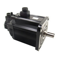
Servomotors
Table of Contents
-
Outline25
-
-
Check Items26
-
Servomotors26
-
-
1 Outline
26-
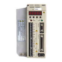
Servopacks27
-
-
2 Selections
35 -
-
-
Without Gears114
-
Without Gears116
-
-
-
-
-
Model247
-
-
-
-
Wire Size275
-
SGMGH Servomotor282
-
Without Brakes287
-
Without Brakes302
-
With Brakes302
-
-
-
Cable Types313
-
-
Flexible Cables
327 -
-
Digital Operator332
-
Noise Filter343
-
Surge Suppressor352
-
INDEXER Module362
-
6 Wiring
365-
Wiring Encoders372
-
Others383
-
-
8 Operation
433-
Trial Operation436
-
Limiting Torque501
-
Advertisement

YASKAWA SGDH SERVOPACK User Manual (447 pages)
Linear Σ Series Servomotors
Table of Contents
-
1 Outline
22-
-
Servopacks27
-
2 Selections
33-
-
Magnetic Way34
-
-
-
-
Three-Phase 200125
-
Three-Phase 400125
-
-
-
-
Flexible Cables155
-
Cable Types157
-
-
Digital Operator163
-
Noise Filter171
-
Surge Suppressor179
-
INDEXER Module189
-
7 Wiring
191-
Wiring Encoders211
-
Others221
-
-
9 Operation
271-
Trial Operation271
-
Limiting Force335
-
-
10 Adjustments
346-
Autotuning347
-
Manual Tuning357
-
-
Analog Monitor374
-
YASKAWA SGDH SERVOPACK User Manual (341 pages)
AC Servo Drives
Brand: YASKAWA
|
Category: Servo Drives
|
Size: 18 MB
Table of Contents
-
1 Outline
21 -
2 Selections
26 -
-
-
-
-
Noise Filter102
-
Surge Absorber104
-
Thermal Relays118
-
6 Wiring
127-
Wiring Encoders134
-
Others143
-
-
8 Operation
183-
Trial Operation186
-
-
Smoothing239
-
Limiting Torque253
-
-
9 Adjustments
263-
Autotuning263
-
Manual Tuning265
-
-
Analog Monitor281
-
Advertisement
Advertisement