YASKAWA S-II Series Instructions Manual
Interface module
Hide thumbs
Also See for S-II Series:
- User manual (447 pages) ,
- User manual (617 pages) ,
- Instructions manual (35 pages)
Table of Contents
Advertisement
Quick Links
サーボパック
AC
Σ-II
シリーズ
取扱説明書
MECHATROLINK
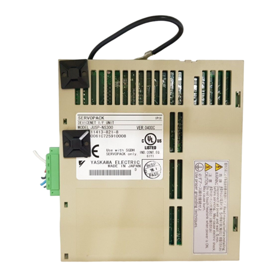
形式:
JUSP-NS100
対象サーボパック形式:
SGDH-E-
製品を安全にお使い頂くために,本書を必ずお読みください。
また,本書をお手元に保管していただくとともに,最終的に本製品をご使用になる
ユーザー様のお手元に確実に届けられるよう,お取り計らい願います。
AC SERVOPACK
Σ
II
-
Series
INSTRUCTIONS
MECHATROLINK Interface Module
Model: JUSP-NS100
Applicable SERVOPACK Model: SGDH-E-
To properly use the product, read this manual thoroughly and retain
for easy reference, inspection, and maintenance. Ensure the end user
receives this manual.
MANUAL NO. TOB-C718-4C
インタフェースモジュール
Advertisement
Table of Contents


Need help?
Do you have a question about the S-II Series and is the answer not in the manual?
Questions and answers