
Related Manuals for YASKAWA E-II SGM H Series


Summary of Contents for YASKAWA E-II SGM H Series
- Page 1 AUDIN - 7 bis rue de Tinqueux - 51100 Reims - France - Tel : 03.26.04.20.21 - Fax : 03.26.04.28.20 - Web : http: www.audin.fr - Email : info@audin.fr...
- Page 2 AUDIN - 7 bis rue de Tinqueux - 51100 Reims - France - Tel : 03.26.04.20.21 - Fax : 03.26.04.28.20 - Web : http: www.audin.fr - Email : info@audin.fr...
- Page 3 Yaskawa. No patent liability is assumed with respect to the use of the information contained herein. Moreover, because Yaskawa is constantly striving to improve its high-quality products, the information contained in this manual is subject to change without notice.
- Page 4 Visual Aids The following aids are used to indicate certain types of information for easier reference. Indicates application examples. EXAMPLE " Indicates supplemental information. INFO Indicates important information that should be memorized, including precautions such as alarm displays IMPORTANT to avoid damaging the devices. Indicates definitions of difficult terms or terms that have not been previously explained in this TERMS manual.
- Page 5 CONTENTS Safety Information ..........Visual Aids .
- Page 6 3.2.6 5.0 kW 400-V Models ..........3 -10 3.2.7 6.0 kW and 7.5 kW 400-V Models .
- Page 7 5.2.3 Using the Encoder Signal Output ........5 -21 5.2.4 Sequence I/O Signals .
- Page 8 5.8 Special Wiring ..........5 -105 5.8.1 Wiring Precautions .
- Page 9 7.2.2 Controlling Operation Through the Digital Operator ......7 -22 7.2.3 Automatic Adjustment of the Speed and Torque Reference Offset .
- Page 10 Host Controller Connection Examples A.1 Connecting the GL-series MC20 Motion Module ....A -2 A.2 Connecting the CP-9200SH Servo Controller Module (SVA) A -3 A.3 Connecting the GL-series B2813 Positioning Module .
- Page 11 Overview Overview J J About this Manual This manual provides the following information for the S-II Series SGMjH/SGDH Servodrives. D Procedures for installing and wiring the Servomotor and Servopack. D Procedures for trial operation of the Servodrive. D Procedures for using functions and adjusting the Servodrives. D Procedures for using the built-in Panel Operator and the Hand-held Digital Operator.
- Page 12 Using This Manual J J Intended Audience This manual is intended for the following users. D Those designing S-II Series Servodrive systems. D Those installing or wiring S-II Series Servodrives. D Those performing trial operation or adjustments of S-II Series Servodrives. D Those maintaining or inspecting S-II Series Servodrives.
- Page 13 Safety Precautions Safety Precautions The following precautions are for checking products upon delivery, installation, wiring, operation, maintenance and inspections. J J Checking Products upon Delivery CAUTION D Always use the Servomotor and Servopack in one of the specified combinations. Not doing so may cause fire or malfunction. J J Installation CAUTION D Never use the products in an environment subject to water, corrosive gases, inflammable gases,...
- Page 14 J J Operation WARNING D Never touch any rotating motor parts while the motor is running. Doing so may result in injury. CAUTION D Conduct trial operation on the Servomotor alone with the motor shaft disconnected from machine to avoid any unexpected accidents. Not doing so may result in injury.
- Page 15 The edition number appears on the front and back covers. S If the manual must be ordered due to loss or damage, inform your nearest Yaskawa representa- tive or one of the offices listed on the back of this manual.
- Page 16 AUDIN - 7 bis rue de Tinqueux - 51100 Reims - France - Tel : 03.26.04.20.21 - Fax : 03.26.04.28.20 - Web : http: www.audin.fr - Email : info@audin.fr...
- Page 17 Checking Products and Part Names This chapter describes the procedure for checking products upon delivery as well as names for product parts. 1.1 Checking S-II Series Products on Delivery 1 - 2 1.1.1 Servomotors ....... . 1 - 2 1.1.2 Servopacks .
- Page 18 Are there any loose screws? Check screws for looseness using a screwdriver. If any of the above items are faulty or incorrect, contact your Yaskawa sales representative or the dealer from whom you purchased the products. 1.1.1 Servomotors...
- Page 19 1.1 Checking S-II Series Products on Delivery J J Model Numbers Standard Servomotors SGMPH -- 01 A A A 2 S S-II Series Servomotor Name 8) Brake and Oil Seal Specifications SGMAH 1: No brake, no oil seal SGMPH S: With oil seal SGMGH B: With 90 VDC brake SGMSH...
- Page 20 Checking Products and Part Names 1.1.1 Servomotors Servomotors with Gears SGMPH -- 01 A A A G 1 2 B S-II Series Servomotor Name 8) Brake Specifications SGMAH 1: Without brake SGMPH B: With 90 VDC brake SGMGH C: With 24 VDC brake SGMSH 7) Shaft End Specifications (See Table 1.8.)
- Page 21 1.1 Checking S-II Series Products on Delivery Table 1.6 Gear Type Code Specification SGMAH SGMPH SGMGH SGMSH HDS planetary low-backlash gear Standard Standard Standard backlash gear Standard Standard With foot Standard Flange mounted Standard IMT planetary low-backlash gear Standard Standard Table 1.7 Gear Ratio (Varies with Gear Type.) Code...
- Page 22 Checking Products and Part Names 1.1.2 Servopacks 1.1.2 Servopacks J J External Appearance and Nameplate Examples Servopack model YASKAWA 200V SERVOPACK SGDH- SGDH-30AE MODE/SET DATA/ CHARGE POWER 24.8 18.6 3.0 (4.0) Serial number Applicable capacity Applicable S-II Series SGDH power supply...
- Page 23 1.1 Checking S-II Series Products on Delivery Table 1.9 Maximum Applicable Capacity (kW) Maximum Applicable Capacity (kW) Servomotor Capacity Servomotor Capacity Symbol Symbol 0.03 0.05 0.10 0.20 0.40 0.45 0.75 1 -7 AUDIN - 7 bis rue de Tinqueux - 51100 Reims - France - Tel : 03.26.04.20.21 - Fax : 03.26.04.28.20 - Web : http: www.audin.fr - Email : info@audin.fr...
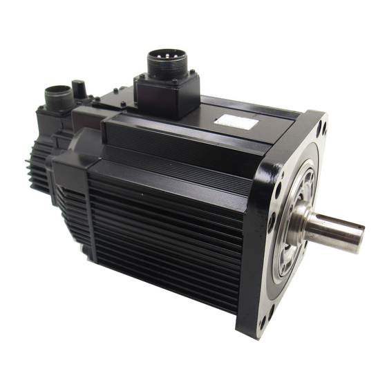
- Page 24 Checking Products and Part Names 1.2.1 Servomotors 1.2 Product Part Names This section describes product part names. 1.2.1 Servomotors The figure below shows part names for Servomotors with or without brakes. Encoder Frame Flange Output shaft 1 -8 AUDIN - 7 bis rue de Tinqueux - 51100 Reims - France - Tel : 03.26.04.20.21 - Fax : 03.26.04.28.20 - Web : http: www.audin.fr - Email : info@audin.fr...
- Page 25 1.2 Product Part Names 1.2.2 Servopacks The figure below shows the part names for Servopacks. Battery Holder Used to house the backup battery for an ab- solute encoder. CN5 Analog Monitor Connector Used to monitor motor speed, torque refer- ence, and other values through a special cable. CN8 Battery Connector Used to connect to the backup battery for an absolute encoder.
- Page 26 Installation This chapter describes precautions for S-II Series Servomotor and Servo- pack installation. 2.1 Servomotors ......2 -2 2.1.1 Storage Temperature .
- Page 27 Installation 2.1.1 Storage Temperature 2.1 Servomotors SGMjH Servomotors can be installed either horizontally or vertically. The service life of the Servomotor will be shortened or unexpected problems will occur if the Servo- motor is installed incorrectly or in an inappropriate location. Always observe the following installa- tion instructions.
- Page 28 2.1 Servomotors 2.1.2 Installation Site SGMjH Servomotors are designed for indoor use. Install the Servomotor in environments that satisfy the following conditions. D Free of corrosive or explosive gases. D Well-ventilated and free of dust and moisture. D Ambient temperature of 0 to 40°C. D Relative humidity of 20 to 80% with no condensation.
- Page 29 Installation 2.1.5 Allowable Shaft Loads 2.1.5 Allowable Shaft Loads Design the mechanical system so thrust and radial loads applied to the Servomotor shaft end dur- ing operation falls within the ranges shown in the Table 2.1. The allowable radial load in the table is the maximum load allowed on the end ofthe output shaft. Table 2.1 Allowable Radial and Thrust Loads for the Servomotor Servomotor Model...
- Page 30 2.1 Servomotors Servomotor Model Allowable Radial Allowable Thrust Reference Load * Load Diagram Fr [N (lbf)] Fs [N (lbf)] (inch) SGMGH- 03AjB SGMGH- 490 (110) 98 (22.0) (2.28) 06AjB 490 (110) 98 (22.0) 09AjB 686 (154) 343 (77.1) 12AjB 1176 (264.3) 490 (110) (3.11) 20AjB...
- Page 31 Installation 2.1.7 Cable Stress 2.1.6 Handling Oil and Water Install a protective cover over the Servomotor if it is used in a location that is subject to water or oil mist. Also use a Servomotor with an oil seal to seal the through shaft section. Install the Servomotor with the connector facing down.
- Page 32 The SGDMServopacksare base-mountedservoamps. Incorrect installationwill cause problems. Al- ways observe the installation instructions below. 2.2.1 Storage Conditions Store the Servopack within the following temperature range if it is stored with the power cable disconnected. - - 20 to 85°C YASKAWA 200V SERVOPACK SGDH- MODE/SET DATA/...
- Page 33 Installation 2.2.4 Orientation 2.2.3 Installation Site Take the following precautions at the installation site. Situation Installation Precaution Installation in a Control Design the control panel size, unit layout, and cooling method so the Panel temperature around the Servopack does not exceed 55°C. Installation Near a Minimize heat radiated from the heating unit as well as any tempera- Heating Unit...
- Page 34 2.2 Servopacks 2.2.5 Installation Follow the procedure below to install multiple Servopacks side by side in a control panel. Cooling fan Cooling fan 50 mm (1.97 in) min. 50 mm (1.97 in) min. 30 mm (1.18 in) min. 10 mm (0.39 in) min. J J Servopack Orientation Install the Servopack perpendicular to the wall so the front panel containing connectors faces outward.
- Page 35 Installation 2.2.6 Voltage Resistance Test 2.2.6 Voltage Resistance Test WARNING D After voltage resistance test, wait at least five minutes before servicing the product. Failure to observe this warning may result in electric shock. Conduct voltage resistance tests under the following conditions. D Voltage: 1500 V rms AC.
- Page 36 Wiring This chapter describes the procedure used to connect S-II Series products to peripheral devices and gives typical examples of main circuit wiring as well as I/O signal connections. 3.1 Connecting to Peripheral Devices ..3 -3 3.1.1 Single-phase (100 V or 200 V) Main Circuit Specifications...
- Page 37 Wiring 3.4 I/O Signals ......3 -18 3.4.1 Examples of I/O Signal Connections ... . 3 -19 3.4.2 List of CN1 Terminals .
- Page 38 3.1 Connecting to Peripheral Devices 3.1 Connecting to Peripheral Devices This section provides examples of standard S-II Series product connections to peripheral devices. It also briefly explains how to connect each peripheral device. 3 -3 AUDIN - 7 bis rue de Tinqueux - 51100 Reims - France - Tel : 03.26.04.20.21 - Fax : 03.26.04.28.20 - Web : http: www.audin.fr - Email : info@audin.fr...
- Page 39 Digital Operator shutting the circuit OFF when over- JUSP-OP02A-2 current is de- tected. Allows the user to set user constants or op- YASKAWA 200V SERVOPACK eration references and SGDH- - Molded-case to display operation or circuit breaker alarm status.
- Page 40 Communication is also possible with a per- Noise Filter sonal computer. Used to eliminate external noise from the power line. Personal Computer YASKAWA 200V SERVOPACK SGDH- MODE/SET DATA/ POWER CHARGE Noise filter Cable model: JZSP-CMS01 to 03...
- Page 41 Communication is also possible with a per- Noise Filter sonal computer. Used to eliminate external noise from the power line. Personal Computer YASKAWA 200V SERVOPACK SGDH- MODE/SET DATA/ POWER CHARGE Noise filter Cable model: JZSP-CMS01 to 03...
- Page 42 3.2 Servopack Internal Block Diagrams 3.2 Servopack Internal Block Diagrams The following sections show internal block diagrams of the Servopacks. 3.2.1 30 to 400 W 200-V and 30 to 200 W 100-V Models Single-phase +10% 200 to 230 V - -15% (50/60Hz) THS1 ¨1...
- Page 43 Wiring 3.2.3 2.0 kW to 5.0 kW 200-V Models 3.2.2 0.5 kW to 1.5 kW 200-V Models Three-phase +10% 200 to 230 V - -15% B1 B2 B3 FAN1 (50/60Hz) ¨1 ¨2 ±12V D2 D3 D4 AC Servomotor Noise filter CHARGE THS1 Gate drive over-...
- Page 44 3.2 Servopack Internal Block Diagrams 3.2.4 6.0 kW to 15.0 kW 200-V Models Regenerative Resistor (option) Three-phase +10% 200 to 230 V - -15% THS1 FAN1 (50/60Hz) ¨ PM1/PM2/PM3 AC Servomotor Line filter CHARGE C7 C6 SCR1 Base drive overcurrent protector\ isolator Voltage Sensor/ Relay drive...
- Page 45 Wiring 3.2.7 6.0 kW and 7.5 kW 400-V Models 3.2.6 5.0 kW 400-V Models Three-phase +10% 380 to 480 V B1 B2 B3 - -15% (50/60Hz) FAN1 AC Servomotor Noise filter CHARGE Gate drive over- current protector RLY2 Voltage Relay drive Gate drive Sensor Control power...
- Page 46 3.2 Servopack Internal Block Diagrams 3.2.8 11.0 kW and 15.0 kW 400-V Models Regenerative Resistor (option) +10% Three-phase - -15% 380 to 480 V B1 B2 (50/60Hz) FAN1 AC Servomotor Noise filter CHARGE SCR1 Gate drive over- current protector Voltage Relay drive Gate drive Sensor...
- Page 47 Wiring 3.3 Main Circuit Wiring This section shows typical examples of main circuit wiring for S-II Series servo products, functions of main circuit terminals, and the power ON sequence. Observe the following precautions when wiring. CAUTION D Do not bundle or run power and signal lines together in the same duct. Keep power and signal lines separated by at least 30 cm (11.81 in).
- Page 48 3.3 Main Circuit Wiring 3.3.1 Names and Descriptions of Main Circuit Terminals Table 3.1 gives the names and a description of main circuit terminals. Table 3.1 Main Circuit Names and Description Name Terminal Main Circuit Description Maximum Applicable Symbol Voltage Servomotor Capacity [kW] +10%...
- Page 49 Wiring 3.3.3 Cable Specifications and Peripheral Devices 3.3.2 Typical Main Circuit Wiring Example The following figure shows a typical example of main circuit wiring (three-phase, 200 V). Servopack SGDH-jjAE +24V (For servo alarm display) Main Main power supply power supply ALM-SG 1SUP QF1: Molded-case circuit breaker (for the inverter)
- Page 50 3.3 Main Circuit Wiring 3.3.4 Servopack Power Losses Table 3.2 shows Servopack power losses at the rated output. Table 3.2 Servopack Power Losses at Rated Output Main Maximum Servopack Model Output Main Control Total Regenerative Circuit Applicable Current Circuit Circuit Power Resistor Power...
- Page 51 Wiring 3.3.5 Wiring Main Circuit Terminal Blocks * 1. Servopacks with a capacity of 30 to 400 W do not have built-in regenerative resistors. If the regenerative energy exceeds the specified value, connect an external regenerative resistor. Refer to 4.6.2 Calculating the Required Capacity of Regenerative Resistors.
- Page 52 3.3 Main Circuit Wiring Fig. A Fig. B 3. Insert the wire core into the opening and then close the opening by releasing the lever or re- moving the screwdriver. J J Preparing the End of the Wire Wire can be used simply by stripping back the outer coating. The following are applicable wire sizes.
- Page 53 Wiring 3.3.5 Wiring Main Circuit Terminal Blocks 3.4 I/O Signals This section describes I/O signals for the SGDH Servopack. 3 -18 AUDIN - 7 bis rue de Tinqueux - 51100 Reims - France - Tel : 03.26.04.20.21 - Fax : 03.26.04.28.20 - Web : http: www.audin.fr - Email : info@audin.fr...
- Page 54 3.4 I/O Signals 3.4.1 Examples of I/O Signal Connections The following diagram shows a typical example of I/O signal connections. SGDH Servopack V-REF Alarm code output Reference speed ALO1 Maximum operating ±2 to ±10 V/rated voltage: 30 VDC ALO2 motor speed Maximum operating T-REF ALO3...
- Page 55 Wiring 3.4.2 List of CN1 Terminals 3.4.2 List of CN1 Terminals The following diagram shows the layout and specifications of CN1 terminals. J J CN1 Terminal Layout 26 /V-CMP- Speed coinci- (/COIN-) (/COIN-) dence detec- dence detec- 27 /TGON+ TGON signal tion output output output...
- Page 56 3.4 I/O Signals J J CN1 Specifications Applicable Receptacles Specifications for Servopack Servopack Solder Type Case Manufacturer Connectors 10250-52A2JL or 10150-3000VE 10350-52A0-008 Manufactured by Su- Equivalent 50-p mitomo 3M Co. Right Angle Plug 3.4.3 I/O Signal Names and Functions The following section describes Servopack I/O signal names and functions.4.1.3 J J Input Signals Signal Name Pin No.
- Page 57 Wiring 3.4.3 I/O Signal Names and Functions Signal Name Pin No. Function Refer- ence Torque T-REF 9 (10) Torque reference input: ±1 to ±10 V/rated motor torque (Input gain can be modi- 4.2.7 fied using a parameter.) Position PULS Corresponds to reference pulse input Input mode 4.2.2 Reference...
- Page 58 3.4 I/O Signals Signal Name Pin No. Function Refer- ence Speed /V-CMP Speed coincidence (output in Speed Control Mode): Detects whether the motor 4.5.4 speed is within the setting range and if it matches the reference speed value. /V-CMP Position /COIN+ Positioning completed (output in Position Control Mode): Turns ON when the 4.5.3...
- Page 59 Wiring 3.4.4 Interface Circuits 3.4.4 Interface Circuits This section shows examples of Servopack I/O signal connection to the host controller. J J Interface for Reference Input Circuits Analog Input Circuit Analog signals are either speed or torque reference signals at the impedance below. D Reference speed input: About 14 kW D Reference torque input: About 14 kW The maximum allowable voltages for input signals is ±12 V.
- Page 60 3.4 I/O Signals D Open-collector Output, Example 2: Using 12-V Power Supply Built into Servopack This circuit uses the 12-V power supply built into the Servopack. The input is not insulated in this case. Host Servopack end controller end PL1, PL2, PL3 terminals +12 V 1.0 kW 150 W...
- Page 61 Wiring 3.4.4 Interface Circuits D Connecting to an Open-collector Output Circuit Alarm code signals are output from open-collector transistor output circuits. Connect an open-collector output circuit through a photocoupler, relay or line receiver cir- cuit. 5 to 12 VDC 5 to 24 VDC Photocoupler Relay Servopack...
- Page 62 3.5 Wiring Encoders 3.5 Wiring Encoders The following sections describe the procedure for wiring a Servopack to the encoder. 3.5.1 Connecting an Encoder (CN2) and Output Signals from the Servopack (CN1) The following diagrams show wiring for incremental and absolute encoders. J J Incremental Encoders Servopack (Note)
- Page 63 Straight: MS3106B20-29S Cable clamp: MS3057-12A Encoder cables are available from Yaskawa. See the data sheets below for more details on the cables. INFO S Refer to S-II Series SGMjH/SGDH User’s Manual: Servo Selection and Data Sheets (Manual No.: SIE-S800-32.1). 3 -28...
- Page 64 3.6 Examples of Standard Connections 3.6 Examples of Standard Connections The following diagrams show examples of standard Servopack connections by specifications and type of control. Design the circuit so that the main circuit power supply turns OFF at emergency stop. 3.6.1 Single-phase Power Supply Specifications Single-phase 200 to 230 VAC + 10%...
- Page 65 Wiring 3.6.1 Single-phase Power Supply Specifications * 1. P represents twisted-pair wires. * 2. The time constant for the primary filter is 47 ms. * 3. Connect when using an absolute encoder. * 4. Used only with an absolute encoder. * 5.
- Page 66 3.6 Examples of Standard Connections 3.6.2 Three-phase Power Supply Specifications (200 V) Single-phase 200 to 230 VAC + 10% –15% (50/60 Hz) Noise filter Power Power Be sure to attach a surge suppressor to the excitation coil of the magnetic contactor and relay. Servomotor A (1) B (2)
- Page 67 Wiring 3.6.2 Three-phase Power Supply Specifications (200 V) * 1. P represents twisted-pair wires. * 2. The time constant for the primary filter is 47 ms. * 3. Connect when using an absolute encoder. * 4. Used only with an absolute encoder. * 5.
- Page 68 3.6 Examples of Standard Connections 3.6.3 Three-phase Power Supply Specifications (400 V) + 10% Single-phase 380 to 480 VAC –15% (50/60 Hz) Noise filter Power Power Be sure to attach a surge suppressor to the excitation coil of the magnetic contactor and relay. Servomotor A (1) B (2)
- Page 69 Wiring 3.6.3 Three-phase Power Supply Specifications (400 V) * 1. P represents twisted-pair wires. * 2. The time constant for the primary filter is 47 ms. * 3. Connect when using an absolute encoder. * 4. Used only with an absolute encoder. * 5.
- Page 70 3.6 Examples of Standard Connections 3.6.4 Position Control Mode + 10% Single-phase 200 to 230 VAC –15% (50/60 Hz) Noise filter Power Power Be sure to attach a surge suppressor to the excitation coil of the magnetic contactor and relay. Servomotor A (1) B (2)
- Page 71 Wiring 3.6.4 Position Control Mode * 1. P represents twisted-pair wires. * 2. The time constant for the primary filter is 47 ms. * 3. Connect when using an absolute encoder. * 4. Used only with an absolute encoder. * 5. Connect an external regenerative resistor between terminals B1 and B2 for Servopacks with a capacity of 6.0 kW or higher.
- Page 72 3.6 Examples of Standard Connections 3.6.5 Speed Control Mode + 10% Single-phase 200 to 230 VAC –15% (50/60 Hz) Noise filter Power Power Be sure to attach a surge suppressor to the excitation coil of the magnetic contactor and relay. Servomotor A (1) B (2)
- Page 73 Wiring 3.6.5 Speed Control Mode * 1. P represents twisted-pair wires. * 2. The time constant for the primary filter is 47 ms. * 3. Connect when using an absolute encoder. * 4. Used only with an absolute encoder. * 5. Set via user constant.
- Page 74 3.6 Examples of Standard Connections 3.6.6 Torque Control Mode Single-phase 200 to 230 VAC + 10% –15% (50/60 Hz) Noise filter Power Power Be sure to attach a surge suppressor to the excitation coil of the magnetic contactor and relay. Servomotor A (1) B (2)
- Page 75 Wiring 3.6.6 Torque Control Mode * 1. P represents twisted-pair wires. * 2. The time constant for the primary filter is 47 ms. * 3. Connect when using an absolute encoder. * 4. Used only with an absolute encoder. * 5. Set via user constant.
- Page 76 Trial Operation This chapter describes a two-step trial operation. Be sure to complete step 1 before proceeding to step 2. 4.1 Two-step Trial Operation ....4 - 2 4.1.1 Step 1: Trial Operation for Servomotor without Load 4 - 3 4.1.2 Step 2: Trial Operation with the Servomotor...
- Page 77 Step 1: Trial Operation for Servomotor without Load Make sure the Servomotor is wired properly and then turn the shaft prior to connecting the Servomotor to the equipment. YASKAWA 200V SERVOPACK SGDH- - -...
- Page 78 D Check main power supply circuit wiring. D Check Servomotor wiring. D Check CN1 I/O signal wiring. Make sure the host controller and other adjustments are completed as much as possible in step 1 (prior to connecting the Servomotor to equipment). YASKAWA 200V SERVOPACK SGDH- MODE/SET...
- Page 79 Servomotor to the equipment. Do not connect anything to the shaft (no-load conditions). Secure the Servomotor mounting plate to the equipment in order to prevent the Servomotor from moving during operation. 2. Check the wiring. YASKAWA 200V SERVOPACK SGDH MODE/SET DATA/...
- Page 80 4.1 Two-step Trial Operation 4. Operate with Panel Operator. YASKAWA 200V SERVOPACK SGDH- Panel Operator MODE/SET DATA/ CHARGE POWER Operate the Servomotor using the Panel Operator. Check to see if the Servomotor runs nor- mally. See 6.2.2ControllingOperationThroughthe Digital Operator formore detailson the proce- dure.
- Page 81 Trial Operation 4.1.1 Step 1: Trial Operation for Servomotor without Load Input Signal Status LED Display OFF (high level) Top LED indicators light. ON (low level) Bottom LED indicators light. The Servomotor will not operate properly if the following signal lines are not wired correctly. Short the signal IMPORTANT lines if they will not be used.
- Page 82 4.1 Two-step Trial Operation If there is noise in the reference voltage for speed control, the “- -” on the left of the 7-segment LED may flash. IMPORTANT J J Operating Using Reference Input The operating procedure here depends on the user constant settings (control mode selection at memory switch Pn000.1).
- Page 83 Trial Operation 4.1.1 Step 1: Trial Operation for Servomotor without Load Operating Procedure in Position Control Mode: Set Pn000.1 to 1 1. Set the user constant Pn200.0 so the reference pulse form is the same as the host controller output form. Selecting the reference pulse form: See 5.2.2 Position Reference.
- Page 84 4.1 Two-step Trial Operation 4.1.2 Step 2: Trial Operation with the Servomotor Connected to the Machine WARNING D Follow the procedure below for step-2 operation precisely as given. Malfunctions that occur after the Servomotor is connected to the equipment not only damage the equip- ment, but may also cause an accident resulting death or injury.
- Page 85 Trial Operation 4.2.1 Servomotors with Brakes 4.2 Supplementary Information on Trial Operation Always refer to this information before starting trial operation in the following instances: D 4.2.1 Servomotor with Brakes D 4.2.2 Position Control by Host Controller 4.2.1 Servomotors with Brakes Use Servomotors with brakes for vertical shaft applications or when external force is applied to the shaft to prevent the shaft from rotating due to gravity or external force when power is lost.
- Page 86 4.2 Supplementary Information on Trial Operation 4.2.2 Position Control by Host Controller If position control from the host controller has not been confirmed, disconnect the Servomotor from the equipment and perform a trial operation, otherwise the Servomotor may run out of con- trol.
- Page 87 Trial Operation 4.3.1 User Constants 4.3 Minimum User Constants and Input Signals This section describes the minimum user constants and input signals required for trial operation. 4.3.1 User Constants See 6.1.6 Operation in User Constant Setting Mode for more details on setting user constants. Turn OFF power once after changing any user constant except Pn300.
- Page 88 4.3 Minimum User Constants and Input Signals 4.3.2 Input Signals Refer to the relevant page for details on each input signal. Input signal selection settings through user constants can be used to eliminate the need for exter- nal short circuits. Signal Name Description Number...
- Page 89 User Constant Settings and Functions Thischapterdescribesthe procedure forsetting andapplying userconstants. 5.1 Settings According to Device Characteristics ..... . . 5 -4 5.1.1 Switching Servomotor Rotation Direction .
- Page 90 User Constant Settings and Functions 5.3.5 Control Mode Selection ..... . . 5 -58 5.4 Setting Stop Functions ....5 -60 5.4.1 Adjusting Offset .
- Page 91 J J Before Reading this Chapter This chapter describes the use of each CN1 connector I/O signals in the SGDHServopack aswell as the procedure for setting the related user constants for the intended purposes. The following sections can be used as references for this chapter. D List of CN1 I/O signals: See 3.4.3 I/O Signal Names and Functions.
- Page 92 User Constant Settings and Functions 5.1.1 Switching Servomotor Rotation Direction 5.1 Settings According to Device Characteristics This section describes the procedure for setting user constants according to the dimensions and per- formance of the equipment used. 5.1.1 Switching Servomotor Rotation Direction The Servopack has a Reverse Rotation Mode that reverses the direction of Servomotor rotation without rewiring.
- Page 93 5.1 Settings According to Device Characteristics 5.1.2 Setting the Overtravel Limit Function The overtravel limit function forces movable equipment parts to stop if they exceed the allow- able range of motion. J J Using the Overtravel Function To use the overtravel function, connect the overtravel limit switch input signal terminals shown below to the correct pins of the Servopack CN1 connector.
- Page 94 User Constant Settings and Functions 5.1.2 Setting the Overtravel Limit Function J J Enabling/Disabling Input Signals Set the following user constants to specify whether input signals are used for overtravel or not. The factory setting is “used.” Pn50A.3 P-OT Signal Mapping (Forward Run Factory Speed/Torque Prohibit Input Signal)
- Page 95 5.1 Settings According to Device Characteristics Pn001.1 Overtravel Stop Mode Factory Speed/Torque Setting: Control, Position Control Stop Mode After stopping Pn001.1 Overtravel setting Stop by dynamic Pn001.0 = 0, 1 brake Coast Pn001.1 = 0 status Coast to a stop Zero clamp Pn001.1 = 1 or 2 Decelerate to a...
- Page 96 User Constant Settings and Functions 5.1.2 Setting the Overtravel Limit Function J J Servo OFF Stop Mode Selection The SGDH Servopack turns OFF under the following conditions: D Servo ON input signal (/S-ON, CN1-40) is turned OFF. D Servo alarm occurs. D Power is turned OFF.
- Page 97 5.1 Settings According to Device Characteristics 5.1.3 Limiting Torques The SGDH Servopack limits torques as follows: D Level 1: Limits maximum output torque to protect the equipment or workpiece. D Level 2: Limits torque after the Servomotor moves the equipment to a specified position (in- ternal torque limit).
- Page 98 User Constant Settings and Functions 5.1.3 Limiting Torques Using /CLT Signal The following section describes the use of the contact output signal /CLT as a torque limit output signal. I/O power supply Servopack + 24 V Photocoupler output Maximum operating voltage CN1-*1 CLT+ per output: 30 VDC...
- Page 99 5.1 Settings According to Device Characteristics Note Multiple signals allocated to the same output circuit are output using OR logic. Set other output signals to a value other than that allocated to the /CLT signal in order to use just the /CLT output signal. See 5.3.4 Output Circuit Signal Al- location.
- Page 100 User Constant Settings and Functions 5.1.3 Limiting Torques The following output signals and monitor methods are used when torque is being limited. S /CLT S Monitor Mode S Un005: Nos. 6 and 7 (With factory settings) (Re- fer to 6.1.7 Operation in Monitor Mode.) S Un006: Depending on output signal allocation conditions.
- Page 101 5.2 Settings According to Host Controller 5.2 Settings According to Host Controller This section describes the procedure for connecting a S-II Series Servo to a host controller, including the procedure for setting related user constants. 5.2.1 Speed Reference Input the speedreference using the following input signal speedreference input. Since thissignal has various uses, set the optimum reference input for the system created.
- Page 102 User Constant Settings and Functions 5.2.1 Speed Reference J J Input Circuit Example Servopack 470 W, 1/2 W min. V-REF + 12 V 2 k W CN1-5 CN1-6 · Always use twisted-pair cable for noise control. Recommended variable resistor: Model 25HP-10Bmanufactured bySakae TsushinKo- gyo Co., Ltd.
- Page 103 5.2 Settings According to Host Controller Using the /P-CON Signal ® Input /P-CON CN1-41 Proportional Control Reference Speed Control, Position Control The /P-CON input signal switches the Speed Control Mode from PI (proportional-integral) to P (proportional) control in order to reduce Servomotor rotation and minute vibrations due to speedreference input drift.
- Page 104 User Constant Settings and Functions 5.2.2 Position Reference Connection Example 2: Open-collector Output Set limiting resistor R1 so that input current, i, falls within the following range: Host controller Servopack Photocoupler 150W CN1-7 PULS /PULS CN1-8 CN1-11 SIGN CN1-12 /SIGN CN1-15 CN1-14 /CLR...
- Page 105 5.2 Settings According to Host Controller J J Selecting a Reference Pulse Form Use the following user constants to select the reference pulse form used. ® Input PULS CN1-7 Reference Pulse Input Position Control ® Input /PULS CN1-8 Reference Pulse Input Position Control ®...
- Page 106 User Constant Settings and Functions 5.2.2 Position Reference Input Pulse Multiplier ´ 4 Number of Servomotor ´ 2 move pulses ´ 1 Input reference pulse PULS (CN1-7) SIGN (CN1-11) The input pulse multiplier function can be used if the reference form is a two-phase pulse train with a 90_ phase differential.
- Page 107 5.2 Settings According to Host Controller Reference Pulse Input Signal Timing Reference Pulse Form Electrical Specifications Remarks Sign + pulse train input t1, t2 0.1 ms Sign (SIGN) t1 t2 SIGN (SIGN + PULS signal) t3, t7 0.1 ms H = Forward reference PULS Maximum reference t4, t5, t6 >...
- Page 108 User Constant Settings and Functions 5.2.2 Position Reference Pn200.1 Description Clear Timing Setting Clears the error counter when the CLR High signal goes high. (CN1-15) Cleared state Error pulses do not accumulate as long as the signal remains high. Clears the error counter on the rising edge of the CLR signal.
- Page 109 5.2 Settings According to Host Controller 5.2.3 Using the Encoder Signal Output Encoder output signals divided inside the Servopack can be output externally. These signals can be used to form a position control loop in the host controller. These outputs explained here.
- Page 110 User Constant Settings and Functions 5.2.3 Using the Encoder Signal Output J J I/O Signals I/O signals are described below. Output ® PAO CN1-33 Encoder Output Phase A Speed/Torque Control, Position Control Output ® /PAO CN1-34 Encoder Output Phase /A Speed/Torque Control, Position Control...
- Page 111 5.2 Settings According to Host Controller ® Input SEN CN1-4 SEN Signal Input Speed/Torque Control ® Input SG CN1-2 Signal Ground Speed/Torque Control Output ® PSO CN1-48 Encoder Output Phase S Speed/Torque Control, Position Control Output ® /PSO CN1-49 Encoder Output Phase /S Speed/Torque Control, Position Control...
- Page 112 User Constant Settings and Functions 5.2.4 Sequence I/O Signals The number of output pulses per revolution is set at this user constant. Set the value using the reference units of the equipment or the controller used. The setting range varies with the encoder used. Preset value: 16 Setting Example...
- Page 113 S External power supply specifications: 24 ±1 VDC, 50 mA min. Yaskawa recommends using the same external power supply as that used for output circuits. The allowable voltage range for the 24-V sequence input circuit power supply is 11 to 25 V. Although a 12-V power supply can be used, contact faults can easily occur for relays and other mechanical contacts under low currents.
- Page 114 User Constant Settings and Functions 5.2.4 Sequence I/O Signals The function allocation for sequence input signal circuits can be changed. See 5.3.3 Input Circuit Signal Allocation for more details. ® Input +24VIN CN1-47 External I/O Power Supply Input Speed/Torque Control, Position Control The external power supply input terminal is common to sequence input signals.
- Page 115 5.2 Settings According to Host Controller 5.2.5 Using the Electronic Gear Function The electronic gear function enables the Servomotor travel distance per input reference pulse to be set to any value. It allows the host controller generating pulses to be used for control without having to consider the equipment gear ratio or the number of encoder pulses.
- Page 116 User Constant Settings and Functions 5.2.5 Using the Electronic Gear Function The number of bits representing the resolution of the applicable encoder is not the same as the number of en- INFO coder signal pulses (A and B phase) output from the Servopack. 3.
- Page 117 5.2 Settings According to Host Controller 6. Set the user constants. Reduce the electronic gear ratio B to the lower terms so that both A and B are integers smaller than 65535, then set A and B in the respective user constants. Electronic Gear Pn202 Ratio (Numerator)
- Page 118 User Constant Settings and Functions 5.2.5 Using the Electronic Gear Function Circular Tables Deceleration Travel distance per load shaft revolution = 360 ratio: 3:1 Incremental encoder: Electonic gear ratio B = 2048 × 4 × 3 = Pn202 13-bit 3600 × 1 Pn203 Preset Val- Pn202...
- Page 119 5.2 Settings According to Host Controller 5.2.6 Contact Input Speed Control The contact input speed control function provides easy-to-use speed control. It allows the user toinitiallyset three different motorspeedswithuserconstants, select one ofthe speedsexternally by contact input, and operate the Servomotor. Servopack /P-CON (/SPD-D) CN1-41...
- Page 120 User Constant Settings and Functions 5.2.6 Contact Input Speed Control Pn000.1 Description Input Signal Setting 3, 4, 5, 6 Contact input /P-CON /P-CL /N-CL Speed setting speed control (/SPD-D) (/SPD-A) (/SPD-B) function used. function used. Direction of 0 reference, rotation etc.
- Page 121 5.2 Settings According to Host Controller 3. Set the soft start time. Pn305 Soft Start Acceleration Unit: Setting Factory Speed Control Time Range: Setting: 0 to 10000 Pn306 Soft Start Deceleration Unit: Setting Factory Speed Control Time Range: Setting: 0 to 10000 The Servopackinternal speedreference controls speedby applyingthis accelerationsetting.
- Page 122 User Constant Settings and Functions 5.2.6 Contact Input Speed Control D Use the following table when contact input speed control is used. Contact Signal User Selected Speed Constant /P-CON(/SPD-D) /P-CL /N-CL Pn000.1 (/SPD-A) (/SPD-B) Stopped by an internal speed reference of 0. Analog speed reference (V-REF) input Pulse reference input...
- Page 123 5.2 Settings According to Host Controller J J Example of Contact Input Speed Control Operation The following example shows operation bycontact input speed control. Using the soft start func- tion reduces physical shock when the speed is changed. Contact Input Speed Control Motor speed Speed 3 +SPEED 3...
- Page 124 User Constant Settings and Functions 5.2.7 Using Torque Control 5.2.7 Using Torque Control The SGDM Servopack limits torque as shown below. D Level 1: Limits maximum output torque to protect the equipment or workpiece. D Level 2: Limits torque after the Servomotor moves the equipment to a specified position (in- ternal torque limit).
- Page 125 5.2 Settings According to Host Controller Application Examples D Tension control D Pressure control Pn000.1 Control Mode Torque Control This is a dedicated Torque Control Mode. Servopack Torque S A torque reference is input from T-REF (CN1-9). T-REF CN1-9 reference S Speed reference input V-REF (CN1-5) cannot be used for Speed V-REF...
- Page 126 User Constant Settings and Functions 5.2.7 Using Torque Control Pn000.1 Control Method Speed Control: When /P-CON (/C-SEL) is ON Set the user constant Pn002.0 as shown below. User Constant Torque Reference Contents Remarks Pn002.0 Input (T-REF) (CN1-9,10) Normal speed control Torque limit input Torque limit speed con- See 5.2.10 for more de-...
- Page 127 5.2 Settings According to Host Controller J J Input Signals Torque Reference Inputs The following input signals are used for torque control. Servopack T-REF CN1-9 Torque Torque reference input CN1-10 reference (Analog voltage input) V-REF CN1-5 Speed Speed reference input CN1-6 reference (Analog voltage input)
- Page 128 User Constant Settings and Functions 5.2.7 Using Torque Control Speed Reference Inputs Refer to 5.2.1. Using the /P-CON Signal ® Input /P-CON CN1-41 Proportional Control, etc. Speed/Torque Control, Position Control The function of the input signal /P-CON varies with the setting at Pn000.1. Servopack P and PI control switching Zero clamp ON/OFF switching...
- Page 129 5.2 Settings According to Host Controller Reference torque Rated torque Reference voltage (V) This reference voltage is set. Two speed limit functions during torque control are available by the user constant setting as shown below. Pn002.1 setting Description Uses speed limit set by Pn407. (internal speed limit function) Uses V-REF (CN1-5 and 6) as external speed limit input and sets speed limit by voltage which input to V-REF and Pn300.
- Page 130 User Constant Settings and Functions 5.2.8 Torque Feed-forward Function Principle of Speed Control INFO Torque reversely proportional to the difference between the speed limit and the speed is fed back to return the system to within the control speed range when the control speed range is exceeded. The actual motor speed limit will thus be increased by negative loads.
- Page 131 5.2 Settings According to Host Controller The torque feed-forward function cannot be used with torque limiting by analog voltage refer- ence described in 5.2.10 Using Torque Limiting by Analog Voltage Reference. J J Setting Torque feed-forward is set using user constant Pn400. The factory setting at Pn400 is 30.
- Page 132 User Constant Settings and Functions 5.2.10 Torque Limiting by Analog Voltage Reference, Function 1 J J Setting The speed feed-forward value is set in user constant Pn300. The factory setting of Pn300 is 600, for which a speed feed-forward value of ±6 V will produce the rated speed.
- Page 133 5.2 Settings According to Host Controller J J Setting The torque limit input gain is set at user constant Pn400. The factory setting at Pn400 is 30. If, for example, the torque limit is ±3 V, then torque is limited to 100% of the rated torque.(A torque value higher than 100% torque is clamped at 100%.) Pn400 Torque...
- Page 134 User Constant Settings and Functions 5.2.11 Torque Limiting by Analog Voltage Reference, Function 2 This torque limiting function cannot be used at the same time as the torque feed-forward func- tion. Confirm the allocation of input signals when using this function. (Refer to 5.3.3 Input Circuit Signal Allocation.) The factory settings are shown in the following table.
- Page 135 5.2 Settings According to Host Controller 5.2.12 Reference Pulse Inhibit Function (INHIBIT) This function inhibits the Servopack from counting input reference pulses during position con- trol. The Servomotor remains locked (clamped) while the function is in use. The /P-CON(/IN- HIBIT) signal is used to enable or disable the function. Servopack Pn000.1 Reference...
- Page 136 User Constant Settings and Functions 5.3.1 User Constants 5.3 Setting Up the Servopack This section describes the procedure for setting user constants to operate the SGDM Servopack. 5.3.1 User Constants The S-IISeriesServopackprovidesmanyfunctionsandhasparameterscalleduser constantsthat allow the user to specify functions and perform fine adjustments. Servopack User Constants A Panel Operator or Digital Operator is...
- Page 137 Use this constant to set the motor speed when operating the Servopack from a Panel or Digital Operator. If the setting is higher than the maximum motor speed of the Servomotor, then the Ser- vomotor will rotate at its maximum speed. SERVOPACK 200V SGDH- YASKAWA MODE/SET DATA/ CHARGE POWER Digital Operator Panel Operator 5.3.3 Input Circuit Signal Allocation...
- Page 138 Description Factory setting for sequence input signal allocation. This setting is the same as Yaskawa SGDB-jADj Servopacks. Enables any sequence input signal settings. In the factory setting, Pn50A.0 is set to 0. Functions in this manual are generally described for the factory set- INFO tings.
- Page 139 5.3 Setting Up the Servopack D Examples of Input Signal Allocation The procedure used to allocate sequence input signals is described using the /S-ON signal as a typical example. Pn50A.1 Description Remarks Setting Inputs the /S-ON signal from the SI0 (CN1-40) input terminal. Signal Polarity: Normal Example: Servo-ON signal (/S-ON) is valid when Inputs the /S-ON signal from the SI1 (CN1-41) input terminal.
- Page 140 User Constant Settings and Functions 5.3.3 Input Circuit Signal Allocation rationsthat donot require thissignal, but unnecessarywiringcanbe eliminated bysetting Pn50A.1 to 8. Signals are input with OR logic when multiple signals are allocated to the same input circuit. INFO 5 -52 AUDIN - 7 bis rue de Tinqueux - 51100 Reims - France - Tel : 03.26.04.20.21 - Fax : 03.26.04.28.20 - Web : http: www.audin.fr - Email : info@audin.fr...
- Page 141 5.3 Setting Up the Servopack D Allocating Other Input Signals Input signal allocation can be changed as shown below. Input Signal User Constant Description Name Applicable Logic Number Setting Proportional Control ON (low level) Pn50A.2 Inputs the signal on the left from SI0 (CN1-40). Reference Reference Inputs the signal on the left from SI1 (CN1-41).
- Page 142 User Constant Settings and Functions 5.3.3 Input Circuit Signal Allocation Input Signal User Constant Description Description Name Applicable Logic Number Setting Control Mode Selection ON (low level) Pn50C.3 0 to F Same as above. (/C-SEL) Zero Clamp ON (low level) Pn50D.0 0 to F Same as above.
- Page 143 5.3 Setting Up the Servopack 5.3.4 Output Circuit Signal Allocation Output signal functions can be allocated to the sequence signal output circuits shown below. Output Factory Setting Comments Connector Connector Terminal Name Terminal Name Terminal Terminal Symbol Name Numbers /V-CMP+ Speed coincidence The signal output (/COIN+)
- Page 144 User Constant Settings and Functions 5.3.4 Output Circuit Signal Allocation User Constant Output Signal Description Number Setting Positioning Pn50E.0 Disabled (Not used for the output signal on the left.) Completed Completed Outputs the signal on the left from the SO1 (CN1-25 and 26) output terminal. (/COIN) (/COIN) Outputs the signal on the left from the SO2 (CN1-27 and 28) output terminal.
- Page 145 5.3 Setting Up the Servopack User Constant Output Terminals Meaning Number Setting SO1 (CN1-25, 26) Pn512.0 Output signal not reversed. Output signal reversed. SO2 (CN1-27, 28) Pn512.1 Output signal not reversed. Output signal reversed. SO3 (CN1-29, 30) Pn512.2 Output signal not reversed. Output signal reversed.
- Page 146 User Constant Settings and Functions 5.3.5 Control Mode Selection 5.3.5 Control Mode Selection The SGDH Servopack offers speed control, position control, torque control, and the other con- trol modes shown in the following table. The following user constant is used to set the control mode. Pn000.1 Control Mode Selection Factory...
- Page 147 5.3 Setting Up the Servopack Contact Input Speed Control Selection (Contact Reference) « Speed Control (Analog Reference) This mode controls speed by switching between contact reference and analog voltage reference speed control. Analogvoltage reference speed control is enabledwhen both/P-CL (/SPD-A)and /N-CL (/SPD-B) input signals are OFF (high level).
- Page 148 User Constant Settings and Functions 5.4.1 Adjusting Offset 5.4 Setting Stop Functions This section describes the procedure used to stop the Servopack stably. 5.4.1 Adjusting Offset J J When the Servomotor Will Not Stop The Servomotor may rotate at very low speed and not stopeven when0 Vis specifiedas the refer- ence voltage for Servopack speed and torque control (analog reference).
- Page 149 5.4 Setting Stop Functions 5.4.2 Using the Dynamic Brake To stop the Servomotor by applying the dynamic brake (DB), set the desired mode in the follow- ing user constant. The Servomotor will stop due to equipment friction if the dynamic brake is not applied.
- Page 150 User Constant Settings and Functions 5.4.3 Using the Zero Clamp Function The dynamic brake is an emergency stop function. Do not repeatedly start and stop the Servomotor using the IMPORTANT servo ON signal (/S-ON) or by repeatedly turning power ON and OFF. 5.4.3 Using the Zero Clamp Function J J Zero Clamp Function The zero clamp function is used for systems where the host controller does not form a position...
- Page 151 5.4 Setting Stop Functions Pn000.1 Setting Control Mode Zero Clamp Control Mode This mode allows the zero clamp Servopack function to be set when the Servo- motor stops. V-REF CN1-5 Speed reference S The speed reference is input from /P-CON V-REF (CN1-5).
- Page 152 User Constant Settings and Functions 5.4.4 Using the Holding Brake When the /ZCLAMP signal is allocated, the zero clamp operation will be used even for speed control (Pn000.1 INFO = 0). 5.4.4 Using the Holding Brake The holding brake is used when a Servodrive controls a vertical axis. In other words, a Servomo- tor with brake prevents the movable part from shifting due to gravity when system power goes OFF.
- Page 153 5.4 Setting Stop Functions Brake Interlock Output Speed/Torque Output Control, Position Control This output signal controls the brake when using a Servomotor with a brake and does not have to be connected when using a Servomotor without a brake. Closed or low level Releases the brake.
- Page 154 User Constant Settings and Functions 5.4.4 Using the Holding Brake J J Brake ON Timing If the equipment moves slightly due to gravity when the brake is applied, set the following user constant to adjust brake ON timing. Pn506 Brake Reference Servo Unit: Setting Factory...
- Page 155 5.4 Setting Stop Functions J J Holding Brake Setting Set the following user constants to adjust brake ON timing so the holding brake is applied when the Servomotor stops. Pn507 Brake Reference Unit: Setting Factory Speed/Torque Output Speed Level Range: Setting: Control, r/min...
- Page 156 User Constant Settings and Functions 5.5.1 Using Servo Alarm and Alarm Code Outputs 5.5 Forming a Protective Sequence This section describes the procedure for using I/O signals from the Servopack to form a protective safety sequence. 5.5.1 Using Servo Alarm and Alarm Code Outputs The basic procedure for connecting alarm output signals is described below.
- Page 157 5.5 Forming a Protective Sequence Alarm codes ALO1, ALO2 and ALO3 are output to indicate each alarm type. The uses of open-collector output signals ALO1, ALO2 and ALO3 is described below. Output ® ALO1 CN1-37 Alarm Code Output Speed/Torque Control, Position Control Output ®...
- Page 158 User Constant Settings and Functions 5.5.2 Using the Servo ON Input Signal 5.5.2 Using the Servo ON Input Signal The basic use and wiring procedure for the Servo ON (/S-ON) input signal (sequence input sig- nal) is described below. Use this signal to forcibly turn OFF the Servomotor from the host con- troller.
- Page 159 5.5 Forming a Protective Sequence 5.5.3 Using the Positioning Completed Output Signal The basic use and wiring procedure for the positioning completed (/COIN) output signal (photo- coupler output signal) is described below. The signal is output to indicate that Servomotoropera- tion is completed.
- Page 160 User Constant Settings and Functions 5.5.4 Speed Coincidence Output Pn500 Positioning Unit: Setting Factory Position Control Completed Width Range: Setting: reference units 0 to 250 Thisuser constant is usedto set output timingfor the positioning completedsignal (/COIN)when the position reference pulse is input and Servomotor operation is completed. Set the number of error pulses in reference units (the number of input pulses defined using the electronic gear function).
- Page 161 5.5 Forming a Protective Sequence Motor speed Pn503 Reference speed /V-CMP is output in this range. The following user constant setting is used to change the CN1 connector terminal that outputs the /V-CMP signal. Pn50E Output Signal Selections 1 Factory Speed Control Setting: 3211...
- Page 162 User Constant Settings and Functions 5.5.5 Using the Running Output Signal 5.5.5 Using the Running Output Signal The basic use and wiring procedures for the running (/TGON) output signal (photocoupler out- put signal) are described below. The signal is output to indicate that the Servomotor is currently operating.
- Page 163 5.5 Forming a Protective Sequence Signals output when Servomotor operation is detected: D /TGON D Status Indication Mode D Monitor Mode Un006 5.5.6 Using the Servo Ready Output Signal The basic use and wiring procedures for the Servo Ready (/S-RDY) output signal (photocoupler output signal) are described below.
- Page 164 User Constant Settings and Functions 5.5.7 Using the Warning Output Signal 5.5.7 Using the Warning Output Signal The basic use andwiringprocedure forthe warning(/WARN) output signal (photocoupleroutput signal) are given below. The signal consists of the following two output signals. /WARN signals: Overload and regenerative overload I/O power supply +24 V Servopack...
- Page 165 5.5 Forming a Protective Sequence Pn50F.3 Output terminals CN1-25, 26 (SO1) /WARN CN1-27, 28 (SO2) Warning output CN1-29, 30 (SO3) signal The following user constant is used to output warning details with an alarm code. Pn001.3 Warning Code Output Selection Factory Speed/Torque Setting:...
- Page 166 User Constant Settings and Functions 5.5.8 Using the Near Output Signal Closed or low level The Servomotor is close to completing opera- tion. (Position error is below the near signal setting range.) OFF: Open or high level The Servomotor is not close to completing op- eration.
- Page 167 5.5 Forming a Protective Sequence 5.5.9 Handling Power Loss The following user constant is used to specify whether the Servomotor holds or continues when a power loss occurs. Pn509 Momentary Hold Time Unit: Setting Factory Speed/Torque Range: Setting: Control, Position Control 20 to 1000 The Servopack turns the Servomotor OFF if it detects an instantaneous voltage drop in the power supply.
- Page 168 User Constant Settings and Functions 5.6 Selecting a Regenerative Resistor When the Servomotor is driven in generator mode, power is returned to the Servopack. This is called regenerative power. The regenerative power is absorbed by charging the smoothing capacitor, but whenthe chargeable energyisexceeded, the regenerative powerisfurther consumedby the regenera- tive resistor.
- Page 169 5.6 Selecting a Regenerative Resistor * 1. The average regenerative power that can be handled is 20% of the rated capacity of the regen- erative resistor built into the Servopack. * 2. The values in parentheses are for the optional JUSP-RA04 Regenerative Resistor Unit. * 3.
- Page 170 User Constant Settings and Functions 5.6.1 External Regenerative Resistors J J Connecting Regenerative Resistors The method for connecting regenerative resistors is shown below. Servopacks with Capacities of 400 W or Less Connect an external regenerative resistor between the Servopack’s B1 and B2 terminals. Servopack Regenerative resistor The user must provide the regenerative resistor.
- Page 171 5.6 Selecting a Regenerative Resistor Connect the Servopack and Regenerative Resistor Unit as shown in the following diagram. Servopack Regenerative Resistor Unit The Regenerative Resistor Unit is sold as an option. Regenerative resistors reach high temperatures, so be careful to cool them. Also use heat-resistant, non-flam- IMPORTANT mable wiring and make sure that the wiring does not come into contact with the resistors.
- Page 172 User Constant Settings and Functions 5.6.2 Calculating the Required Capacity of Regenerative Resistors 5.6.2 Calculating the Required Capacity of Regenerative Resistors J J By Means of a Simple Calculation When driving a Servomotor normally with the horizontal axis, check the external regenerative resistor requirements using the calculation method shown below.
- Page 173 5.6 Selecting a Regenerative Resistor Voltage Series Allowable Frequencies in Regeneration Mode (r/min) Capacity Symbol 200 V SGMAH SGMPH SGMGH-jAjA SGMGH-jAjB SGMSH 400 V SGMGH SGMSH SGMUH Voltage Series Allowable Frequencies in Regeneration Mode (r/min) Capacity Symbol 200 V SGMGH-jAjA SGMGH-jAjB SGMSH SGMDH...
- Page 174 User Constant Settings and Functions 5.6.2 Calculating the Required Capacity of Regenerative Resistors D n = J : Servomotor rotary inertia (kg·m ) (oz·in·s :Motor axis conversion load inertia (kg·m ) (oz·in·s Servopacks with Capacities of 6.0 kW or More Servopacks with capacities of 6.0 kW or more do not have built-in regenerative resistors.
- Page 175 5.6 Selecting a Regenerative Resistor Note 1. The “0.2” in the equation for calculating W is the value for when the regenerative resistor’s utilized load ratio is 20%. 2. The units for the various symbols are as follows: : Energy joules (J) :Load torque (N·m) (oz·in) to E :Regenerative resistor required capacity (W) t...
- Page 176 User Constant Settings and Functions 5.6.2 Calculating the Required Capacity of Regenerative Resistors 2. Servomotor for 200 V S S SGMAH Servomotor, 200 V S S SGMPH Servomotor, 200 V SGMPH- SGMAH- Loss Loss 01A, 02A Torque (%) Torque (%) S S SGMGH Servomotor, 200 V, 1500 r/min S S SGMGH Servomotor, 200 V, 1000 r/min 2800...
- Page 177 5.6 Selecting a Regenerative Resistor 3. Servomotor for 400 V S S SGMGH Servomotor, 400 V, 1500 r/min S SGMSH Servomotor, 400 V 2500 1400 SGMGH- - SGMSH- - 05D A 1200 09D A 2000 13D A 1000 20D A 30D A 1500 44D A...
- Page 178 User Constant Settings and Functions 5.6.2 Calculating the Required Capacity of Regenerative Resistors Servopack’s Absorbable Energy The followingdiagramsshowthe relationshipbetween the Servopack’s input power supplyvolt- age and its absorbable energy. S S Servopack for 100 V Servopack SGDH- A5BD to 02BD A3BD Absorbable energy AC input power supply voltage (Vrms)
- Page 179 5.6 Selecting a Regenerative Resistor S S Servopack for 400 V, Continued Servopack SGDH- 1ADE 1EDE 60DE 75DE 50DE (J) Absorbable energy AC input power supply voltage (Vrms) 5 -91 AUDIN - 7 bis rue de Tinqueux - 51100 Reims - France - Tel : 03.26.04.20.21 - Fax : 03.26.04.28.20 - Web : http: www.audin.fr - Email : info@audin.fr...
- Page 180 User Constant Settings and Functions 5.6.2 Calculating the Required Capacity of Regenerative Resistors 5.7 Absolute Encoders If a motor with an absolute encoder is used, a system to detect the absolute position can be made in the host controller. If such a system is to be combined with a host controller, use a Servomotor with an absolute encoder.
- Page 181 5.7 Absolute Encoders 5.7.1 Interface Circuit The following diagram shows the standard connections for an absolute encoder mounted to a Servomotor. Host controller Servopack PG5V H (1) OSEN 7406 PG0V G (2) BAT (+) T (3) BATO Battery BAT (- -) S (4) Serial interface Line driver...
- Page 182 User Constant Settings and Functions 5.7.2 Selecting an Absolute Encoder 5.7.2 Selecting an Absolute Encoder Select the absolute encoder usage with the following user constant. Pn002.2 Absolute Encoder Usage Factory Speed, Torque Setting: Control, Position Control “0” in the following table must be set to enable the absolute encoder. Pn002.2 Setting Contents Use the absolute encoder as an absolute encoder.
- Page 183 5.7 Absolute Encoders Batter connector (CN8) Battery carrying space SGDH Ver. POWER BATTERY MODE/SET DATA/ Figure 5.3 Servopacks with Capacities of 6.0 to 15 kW PROHIBITED D Install the battery at either the host controller or the Servopack. It is dangerous to install batteries at both simultaneously, because that sets up a loop circuit between the batteries.
- Page 184 User Constant Settings and Functions 5.7.4 Absolute Encoder Setup 4. Pressing the Up Cursor Key will change the display as shown below. Continue pressing the Up Cursor Key until “PGCL5” is displayed. If an erroneous key entry is made, “nO_OP” will flash for one second and the display will return to the auxiliary function mode.
- Page 185 5.7 Absolute Encoders 5. When “PGCL5” is displayed, press the MODE/SET Key. The display will change as fol- lows, and the absolute encoder’s multi-turn data will be cleared. Flashes for 1 second. 6. Press the DATA/SHIFT Key to return to the auxiliary function mode. This completes the absolute encoder’s setup operation.
- Page 186 User Constant Settings and Functions 5.7.5 Absolute Encoder Reception Sequence J J Contents of Absolute Data D Serial data: Indicates how many turns the motor shaft has made from the reference position (position specified at setup). D Initial incremental pulse:Outputs pulses at the same pulse rate as when the motor shaft ro- tates from the origin to the current position at approximately 2500 r/min (for 16 bits when the dividing pulse is at the factory setting) Reference position (setup)
- Page 187 5.7 Absolute Encoders J J Detailed Signal Specifications PAO Serial Data Specifications The number of revolutions is output in five digits. Data Transfer Method Start-stop Synchronization (ASYNC) Baud rate 9600 bps Start bits 1 bit Stop bits 1 bit Parity Even Character code ASCII 7-bit code...
- Page 188 User Constant Settings and Functions 5.7.5 Absolute Encoder Reception Sequence Number of revolutions: “0” to “9” Absolute position within one revolution: “0” to “9” “+”or “- -” “,” “CR” “P” 0 0 0 0 0 1 0 1 0 Stop bit Data Even parity Start bit...
- Page 189 5.7 Absolute Encoders J J Transferring Alarm Contents When an absolute encoder is used, SEN signals can be utilized to transfer the alarm detection contents from PAO outputs to the host device as serial data. Table 5.1 Alarm Contents Output Example SEN Signal “L”...
- Page 190 User Constant Settings and Functions 5.7.6 Multiturn Limit Setting Pn205 Multiturn Limit Setting Unit: Setting Factory Speed/Torque Range: Setting: Control, Position Control 0 to 65535 65535 If the Multiturn Limit Setting is set to 65535 (factory setting), the multiturn data will vary from - - 32768 to 32767.
- Page 191 5.7 Absolute Encoders The multiturn limit setting in the Encoder can be changed only when the Multiturn Limit Disagreement alarm INFO has occurred. After changing the setting, turn the power supply OFF and then back ON. J J Changing the Setting with the Hand-held Digital Operator 1.
- Page 192 User Constant Settings and Functions 5.7.6 Multiturn Limit Setting 4. Press the MODE/SET Key. The following display will appear and the multiturn limit setting in the absolute encoder will be changed. Flashes for one second. 5. Press the DATA/SHIFT Key for at least one second to return to the auxiliary function mode. This completes the procedure to change the multiturn limit setting in the absolute encoder.
- Page 193 5.8.1 Wiring Precautions To ensure safe and stable operation, always observe the following wiring precautions. Always use the following cables for reference input and encoder wiring. IMPORTANT Cable Type Yaskawa Drawing No. Maximum Allowable Length Reference Input Twisted-pair wires JZSP-CKI01...
- Page 194 User Constant Settings and Functions 5.8.1 Wiring Precautions 5. To prevent malfunction due to noise, take the following actions: S Position the input reference device and noise filter as close to the Servopack as possible. S Always install a surge absorber circuit in the relay, solenoid and electromagnetic contactor coils. S The distance between a power line (such as a power supply line or motor cable) and a signal line must be at least 30 cm.
- Page 195 5.8 Special Wiring J J QF or Fuse According to Power Capacity The following table shows the QF or fuse capacity for each power supply capacity. Power Capacity Current Capacity Servopack Model Main Circuit Main Circuit Applicable Applicable per Servopack per Servopack per QF or Fuse per QF or Fuse...
- Page 196 User Constant Settings and Functions 5.8.1 Wiring Precautions Power Capacity Power Capacity Current Capacity Current Capacity Servopack Model Main Circuit Main Circuit Applicable Applicable per Servopack per Servopack per QF or Fuse per QF or Fuse Power Supply Power Supply Motor Motor Capacity (kW)
- Page 197 5.8 Special Wiring 5.8.2 Wiring for Noise Control J J Wiring Example This Servopack uses high-speed switching elements in the main circuit. It may receive “switch- ing noise” from these high-speed switching elements if wiring or grounding around the Servo- pack is not appropriate.
- Page 198 User Constant Settings and Functions 5.8.2 Wiring for Noise Control J J Correct Grounding Grounding the Motor Frame Always connect servomotor frame terminal FG to the Servopack ground terminal . Also be sure to ground the ground terminal If the servomotor is grounded via the machine, a switching noise current will flow from the Ser- vopack power unit through motor stray capacitance.
- Page 199 FS5559-80-34 Note These noise filters are manufactured by Tokin Corp. and available from Yas- kawa. For noise filters, contact your nearest Yaskawa representatives. Always observe the following installation and wiring instructions. Incorrect use of a noise filter halves its benefits.
- Page 200 User Constant Settings and Functions 5.8.2 Wiring for Noise Control D Connect the noise filter ground wire directly to the ground plate. Do not connect the noise filter ground wire to other ground wires. Filter Filter Shielded ground wire Thick and short D When grounding a noise filter inside a Unit.
- Page 201 5.8 Special Wiring 5.8.3 Using More Than One Servodrive The following diagram is an example of the wiring when more than Servodrive is used. Power Supply R S T Power Power Power supply Noise filter SGMjH Servomotor SGDH Servopack +24V 31 ALM+ 32 ALM- - SGMjH...
- Page 202 User Constant Settings and Functions 5.8.4 Extending Encoder Cables 5.8.4 Extending Encoder Cables Standard encoder cables have a maximum length of 20 m. If a longer cable is required, prepare an extension cable as described below. The maximum allowable cable length is 50 m. For more details, refer to the S-II Series SGMjH/SGDH User’s Manual: Servo Selection and Data Sheets (SIE-S800-32.1).
- Page 203 5.8 Special Wiring D Preparing Encoder Cables S Encoder Connector at Ser- S Cable Line S Encoder Connector at Servomotor vopack For SGMAH and SGMPH Ser- vomotors For SGMGH, SGMSH, SGMDH and SGMUH Servo- motors (JZSP-CMP9-1) (JZSP-CMP19-j) Maximum length: 50 m (1968.50 in) 5 -115 AUDIN - 7 bis rue de Tinqueux - 51100 Reims - France - Tel : 03.26.04.20.21 - Fax : 03.26.04.28.20 - Web : http: www.audin.fr - Email : info@audin.fr...
- Page 204 User Constant Settings and Functions 5.8.5 400-V Power Supply Voltage 5.8.5 400-V Power Supply Voltage CAUTION D Do not connect the Servopack for 100 V and 200 V directly to a voltage of 400 V. The Servopack will be destroyed. There are four types of SGDH Servopacks, for the power supply voltages: Single-phase 100 VAC, single-phase 200 VAC, three-phase 200 VAC, and three-phase 400 VAC.
- Page 205 5.8 Special Wiring When using a 400-V class power supply, turn the power supply ON and OFF at the primary side of thee voltage conversion transformer. Transformer inductance will cause a surge voltage if the power is turned ON and OFF at the secondary, damag- IMPORTANT ing the Servopack.
- Page 206 User Constant Settings and Functions 5.8.6 DC Reactor for Harmonic Suppression J J DC Reactor Specifications The following table shows the specifications for the DC reactors provided by Yaskawa. Reactor Specifications Applicable Servopacks Reactor Model Model Inductance Rated current (mH)
- Page 207 Servo Adjustment This chapter describes the functions required for servo adjustment. Find the required information by selecting the section from the following table of contents. 6.1 Smooth Operation ..... 6 - 2 6.1.1 Using the Soft Start Function .
- Page 208 Servo Adjustment 6.1.1 Using the Soft Start Function 6.1 Smooth Operation This section provides technical information on the smooth operation of Servomotors. 6.1.1 Using the Soft Start Function The soft start function adjusts progressive speed reference input inside the Servopack so that ac- celeration and deceleration can be as constant as possible.
- Page 209 6.1 Smooth Operation 6.1.2 Smoothing A filter can be applied in the Servopack to a constant-frequency reference pulse. Use the follow- ing user constant to set the type of filter to be applied. Pn207.0 Position Reference Filter Factory Setting: Position Control Selection Either an acceleration/deceleration or average movement filter can be selected.
- Page 210 Servo Adjustment 6.1.4 Adjusting Offset 6.1.3 Adjusting Gain If speed loop gain or position loop gain exceeds the allowable limit for the servo system includ- ing the machine to be controlled, the system will tend to vibrate or become too sensitive. Smooth operation is not possible under such conditions, so reduce each loop gain value to an appropriate value.
- Page 211 6.1 Smooth Operation 6.1.5 Setting the Torque Reference Filter Time Constant If there is machine vibration which may be caused by the servodrive, try adjusting the filter time constant in Pn401. This may stop the vibration. Pn401 Torque Reference Unit: Setting Factory Speed/Torque...
- Page 212 Servo Adjustment 6.2.1 Setting Servo Gain 6.2 High-speed Positioning This section provides technical information on high-speed positioning. 6.2.1 Setting Servo Gain Use the servo gain setting function in the following cases. D To check each servo gain value that is automatically set after auto-tuning. D To directly set each of the above servo gain values in another Servopack.
- Page 213 6.2 High-speed Positioning J J Setting Position Loop Gain Set the following position loop-related user constant as required. Pn102 Position Loop Gain (Kp) Unit: Setting Factory Speed Control, Range: Setting: Position Control 1 to 2000 The above constant is the position loop gain for the Servopack. The higher the position loop gain, the smaller the position control error will be.
- Page 214 Servo Adjustment 6.2.3 Using Proportional Control 6.2.2 Using Feed-forward Control The time required for positioning can be shortened with feed-forward control by setting the fol- lowing user constant. Pn109 Feed-forward Unit: Setting Factory Speed Control Range: Setting: Position Control 0 to 100 Thisuserconstant is set to applyfeed-forward frequencycompensation toposition control inside the Servopack.
- Page 215 6.2 High-speed Positioning J J Methods for Using Proportional Control Proportional control can be used in the following two ways. D When operation is performed by sending speed references from the host controllerto the Ser- vopack, the host controller can selectively use P control mode for particular conditions only. This method can suppress overshooting and shorten setting time.
- Page 216 Servo Adjustment 6.2.5 Using Mode Switch 6.2.5 Using Mode Switch Use the mode switch function for the following purposes. D To suppress overshooting during acceleration or deceleration (for speed control). D To suppress undershooting during positioning and to shorten the setting time (for position control).
- Page 217 6.2 High-speed Positioning Setting Selection User Constant to Set Unit Set Detective Point Uses torque reference as the Pn10C Percentage of rated torque: detection point. (Standard set- ting) Uses speed reference input as Pn10D Motor speed: r/min the detection point. Uses acceleration as the detec- Pn10E Motor acceleration:...
- Page 218 Servo Adjustment 6.2.5 Using Mode Switch Speed reference Motor speed Speed Pn10D Time P control PI control control Operating Example EXAMPLE " In this example, the mode switch is used to reduce setting time. Generally, speed loop gain must be increased to reduce setting time. Using the mode switch suppresses the occurrence of overshooting and undershooting when speed loop gain is increased.
- Page 219 6.2 High-speed Positioning Error Pulse Used as Detection Point This setting is enabled for position control operation only. If an error pulse exceeds the value set in user constant Pn10F, the speed loop switches to P con- trol. Reference Motor speed Speed Time Deviation...
- Page 220 Servo Adjustment 6.2.6 Speed Feedback Compensation This function is available provided that the inertia ratio set in Pn103 is correct. Therefore, perform online auto- INFO tuning to obtain and save the results as the user constants. Refer to 6.3 Autotuning for details. Alternatively, directly set the inertia ratio.
- Page 221 6.2 High-speed Positioning Speed feedback compensation usually makes it possible to increase the speed loop gain and position loop gain. IMPORTANT The machinery may vibrate excessively if the compensation value greatly changes or Pn110.1 is set to “1” (i.e., no speed feedback compensation enabled) after increasing the speed loop gain or position loop gain. 6 -15 AUDIN - 7 bis rue de Tinqueux - 51100 Reims - France - Tel : 03.26.04.20.21 - Fax : 03.26.04.28.20 - Web : http: www.audin.fr - Email : info@audin.fr...
- Page 222 Servo Adjustment 6.3.1 Online Autotuning 6.3 Autotuning If positioning is taking a long time, the speed loop gain or position loop gain of the servo system may not be set properly. If the gain settings are wrong, set them properly in accordance with the configura- tion and rigidity of the machinery.
- Page 223 6.3 Autotuning Disable the online autotuning function if tuning is not possible. (See 6.4.3.) Do not use online autotuning in the following cases. IMPORTANT S When driving using Torque Control Mode. S When using IP control for the speed loop. S When using the torque feed-forward function.
- Page 224 Servo Adjustment 6.3.1 Online Autotuning J J Setting User Constants for Online Autotuning The followingflowchart showsthe procedure forsettingthe user constantsfor online autotuning. Start Operate with factory settings of constants Operation Load inertia changes? Set to always perform tuning. (Set Pn110.0 to 1) Operation Adjust the rigidity setting (Set in Fn001)
- Page 225 6.3 Autotuning 6.3.2 Machine Rigidity Settings for Online Autotuning For the machine rigidity settings at the time of online autotuning, select the target values for speed loop gain and position loop gain of the servo system. Any of the following ten levels of rigidity can be selected.
- Page 226 Servo Adjustment 6.3.2 Machine Rigidity Settings for Online Autotuning 3. Press the Up or Down Cursor Key to select the rigidity setting. Up Cursor Key Down Cursor Key 4. Press the DSPL/SET Key. The following display will flash for 1 second and then the rigidity setting will be changed.
- Page 227 6.3 Autotuning 6.3.3 Saving Results of Online Autotuning Online autotuning always processes the latest load inertia to renew data so that the speed loop gain will reach the target value that has been set. When the Servopack is turned off, all the pro- cessed data is lost.
- Page 228 Servo Adjustment 6.3.3 Saving Results of Online Autotuning 3. Press the DSPL/SET Key. The following display will flash for 1 second and then the inertia ratio will be saved. Flashes for 1 s. 4. Press the DATA/ENTER Key to return to the auxiliary function mode. This completes the procedure for saving the results of online autotuning.
- Page 229 6.3 Autotuning 6.3.4 User Constants Related to Online Autotuning This section provides information on a variety of user constants related to online autotuning. J J Online Autotuning Method The following user constant is used for setting the autotuning conditions. Pn110.0 Online Autotuning Method Factory Speed Control,...
- Page 230 Servo Adjustment 6.3.4 User Constants Related to Online Autotuning J J Friction Compensation Selection Use the following user constant to enable or disable friction compensation to determine whether or not the friction of the servo system is to be taken into consideration for the calculation of load inertia.
- Page 231 6.4 Servo Gain Adjustments 6.4 Servo Gain Adjustments This section describes information on the basic rules of gain adjustments in the Servopack, adjust- ment methods in a variety of cases, and reference set values. 6.4.1 Servo Gain User Constants The following user constants must be set properly for servo gain adjustments. D Pn100: Speed loop gain D Pn101: Speed loop integral time constant D Pn102: Position loop gain...
- Page 232 Servo Adjustment 6.4.2 Basic Rules of Gain Adjustment D Generally speaking, the responsiveness of the position loop cannot be higher than that of the speed loop. Therefore, to increase the position loop gain, you must first increase the speed loop gain. If only the position loop gain is increased, oscillation will result in the speed refer- ence and positioning time will increase, not decrease.
- Page 233 6.4 Servo Gain Adjustments 6.4.3 Making Manual Adjustments The autotuningfunctionusesa gainadjustment algorithm witha comparativelylarge safetymar- ginbyconsideringa varietyofmechanical systemsto whichthe Servopackis applied. Therefore, the Servopack may not satisfy the response characteristics of some applications. The autotuning function is not available to machines with low rigidity or high fluctuation. In such cases, observe the mechanical systems and make manual adjustments of user constants.
- Page 234 Servo Adjustment 6.4.3 Making Manual Adjustments D Torque Reference Filter Time Constant (Pn401) If the mechanical system uses ball screws, torsion resonance may result, in which case the oscillation noise will be a high-pitched tone. The oscillation may be stopped by increasing the time constant of the torque reference filter.
- Page 235 6.4 Servo Gain Adjustments J J Position Control User Constants The following user constants are used. D Speed Loop Gain (Pn100) Thisuserconstant is usedfor determiningthe response speed ofthe speedloop. The response speed increases if the constant is set to a large value provided that the mechanical system does not vibrate.
- Page 236 Servo Adjustment 6.4.3 Making Manual Adjustments D Position Loop Gain (Pn102) The responsiveness of the servo system is determined by the position loop gain. The re- sponse speed increases if the position loop gain is set to a high value, so the time required for positioning will be shortened.
- Page 237 6.4 Servo Gain Adjustments Feed-forward Functions The responsiveness is increased by using one of the feed-forward functions. A feed-forward function is not so effective, however, if the position loopgain isset toa highenough value. Adjust the feed-forward set value of Pn109 as described below. 1.
- Page 238 Servo Adjustment 6.4.4 Gain Setting Reference Values J J Machines with High Rigidity These machines are directly connected to ball screws. Example: Chip mounting machine, bonding machine, high-precision machine tool Position Loop Gain Speed Loop Gain (Pn100) Speed Loop Integral Time (Pn102) [1/s] [Hz] Constant (Pn101) [ms]...
- Page 239 6.5 Analog Monitor 6.5 Analog Monitor The analog monitor can observe a variety of signals through analog voltages. Analog monitor signals must be observed through the CN5 connector using DE9404559 dedicated cable. Black Black White Cable Color Signal Name Description White Analog monitor 1 Torque reference: 1 V/100% rated torque...
- Page 240 AUDIN - 7 bis rue de Tinqueux - 51100 Reims - France - Tel : 03.26.04.20.21 - Fax : 03.26.04.28.20 - Web : http: www.audin.fr - Email : info@audin.fr...
- Page 241 Using the Digital Operator This chapter describes the basic operation of the Digital Operator and the features it offers. All constant settings and motor operations can be executed by simple, convenient operations. Operate the Digital Opera- tor as you read through this chapter. 7.1 Basic Operation .
- Page 242 There is no need to turn OFF the Servopack toconnect thisHand-held Operatorto the Servopack. Refer to the following illustrations to connect the Hand-held Digital Operator to the Servopack. Hand-held Digital Operator Built-in Panel Operator JUSP-OP02-A YASKAWA 200V SERVOPACK SGDH- DATA/...
- Page 243 7.1 Basic Operation 7.1.2 Functions The Digital Operator can be used user constant settings, operating references, and status dis- plays. This section provides information on the keys and their functions available from the initial dis- plays. Hand-held Digital Operator Name Function RESET Key Press this key to reset the servo alarm.
- Page 244 Using the Digital Operator 7.1.3 Resetting Servo Alarms Built-in Panel Operator Name Function YASKAWA 200V SERVOPACK SGDH- Up Cursor Key S Press this key to set user constants or dis- play the set values of user constants. S Press the Up Cursor Key to increase the set value.
- Page 245 7.1 Basic Operation 7.1.4 Basic Mode Selection The basic mode selectionofthe Digital Operatoris usedfor indicatingthe statusof the Servopack in operation and setting a variety of user constants and operation references. The status display, auxiliary function, user constant setting, and monitor modes are the basic modes.
- Page 246 Using the Digital Operator 7.1.5 Status Display Mode Speed and Torque Control Mode Bit Data Code Speed Coincidence* BaseBlock Control Power ON TGON Speed Reference input Power Ready Torque Reference Input This indicator is always lit when the Servopack is in torque control mode. The following tables list bit data items, codes, and their meanings.
- Page 247 7.1 Basic Operation Position Control Mode Bit Data Code Positioning Completed Baseblock Control Power ON TGON Reference Pulse Input Power Ready Error Counter Clear Input The following tables list bit data items, codes, and their meanings. Table 7.3 Bit Data and Meanings in Position Control Mode Bit Data Meaning Control Power ON...
- Page 248 Using the Digital Operator 7.1.6 Operation in User Constant Setting Mode 7.1.6 Operation in User Constant Setting Mode Functions can be selected or adjusted by setting user constants. There are two types of user constants. One type requires value setting and the other requires function selection. These two types use different setting methods.
- Page 249 7.1 Basic Operation Using the Panel Operator YASKAWA 200V SERVOPACK SGDH- 1. Press the MODE/SET Key to select the user constant setting mode. MODE/SET DATA/ CHARGE POWER 2. Press the Up or Down Cursor Key to select the user constant number to set. (Pn507 is se- lected in this example.)
- Page 250 Using the Digital Operator 7.1.6 Operation in User Constant Setting Mode J J Function Selection User Constants Types of Function Selection User Constants The following table shows user the constants used for selecting Servopack functions. Category User Name Factory Remarks Constant Setting Function Selection...
- Page 251 7.1 Basic Operation User constant settings are displayed in two patterns as shown below. User constants for function selec- Hexadecimal display for each tion digit User constants for constant set- Decimal display in five digits tings Since each digit in the function selection user constants has a significant meaning, the value can only be changed for each individual digit.
- Page 252 Using the Digital Operator 7.1.6 Operation in User Constant Setting Mode J J Changing Function Selection User Constant Settings Using the Hand-held Digital Operator 1. Press the DSPL/SET Key to select the constant setting mode. 2. Select the user constant number to be set. Press the Left or Right Cursor Key to select the digit.
- Page 253 7.1 Basic Operation Using the Panel Operator YASKAWA 200V SERVOPACK SGDH- 1. Press the MODE/SET Key to select the constant setting mode. MODE/SET DATA/ CHARGE POWER 2. Press the Up or Down Cursor Key to select the user constant number to be set. (Pn000 is selected in this example.)
- Page 254 Data 4. Press the DATA/ENTER Key once more to return to the monitor number display. This is how to display 1500, the contents of monitor number Un000. With the Panel Operator YASKAWA 200V SERVOPACK SGDH- 1. Press the MODE/SET Key to select the monitor mode.
- Page 255 7.1 Basic Operation J J Contents of Monitor Mode Display The following table shows contents of the monitor mode display. Monitor Monitor Display Unit Remarks Number Un000 Actual motor speed r/min Un001 Input speed reference r/min Un002 Internal torque reference Value for rated torque Un003 Rotation angle 1...
- Page 256 Using the Digital Operator 7.1.7 Operation in Monitor Mode J J Sequence I/O Signal Monitor Display The following section describes the monitor display for sequence I/O signals. Input Signal Monitor Display Top: OFF (“H” level) Bottom: ON (“L” level) Number 7 6 5 4 3 2 1 LED Number Input Terminal Name...
- Page 257 7.1 Basic Operation Output Signal Monitor Display Top: OFF (“H” level) Bottom: ON (“L” level) 4 3 2 1 Number 7 6 5 LED Number Output Terminal Name Factory Setting (CN1-31, -32) SO1 (CN1-25, -26) /COIN or /V-CMP SO2 (CN1-27, -28) /TGON SO3 (CN1-29, -30) /S-RDY...
- Page 258 Rightmost 16-bit Data 5. Press both the Up and Down Cursor Keys simultaneously to clear the 32-bit counter data. 6. Press the DATA/ENTER Key once more to return to the monitor number display. Using the Panel Operator YASKAWA 200V SERVOPACK SGDH- 1.
- Page 259 7.2 Applied Operation 7.2 Applied Operation This section describes how to apply the basic operations using the Digital Operator to run and adjust the motor. Read the basic operations described in section 7.1 before proceeding to this section. User constants for applied operation can be set in the auxiliary function mode. The following table shows the user constants in the auxiliary function mode.
- Page 260 Using the Digital Operator 7.2.1 Operation in Alarm Traceback Mode Note These user constants and those indicated as Pnjjj are displayed as shown below if their passwords are set (Fn010). These user constants cannot be changed. Flashing for one second 7.2.1 Operation in Alarm Traceback Mode The alarm traceback mode can display up to ten alarms that have occurred, thus making it pos- sible to check what kind of alarms have been generated.
- Page 261 7.2 Applied Operation Using the Panel Operator YASKAWA 200V SERVOPACK SGDH- 1. Press the MODE/SET Key to select the “Displaying alarm traceback data (Fn000)” in the MODE/SET DATA/ CHARGE POWER auxiliary function mode. Alarm Traceback Display 2. Press the DATA/SHIFT for a minimum of one second to display the alarm traceback data.
- Page 262 For motor speed setting procedure, refer to 7.1.6 Operation in User Constant Setting Mode and 5.3.2 Setting JOG Speed. Panel Servopack YASKAWA 200V Operator SERVOPACK SGDH- MODE/SET...
- Page 263 (with motor power turned OFF). Alternatively, press the SVON Key to set to the servo OFF state. This disables operation under Digital Operator control. Using the Panel Operator YASKAWA 200V SERVOPACK SGDH- 1. Press the MODE/SET Key to select Fn002 in the auxiliary function mode.
- Page 264 Using the Digital Operator 7.2.3 Automatic Adjustment of the Speed and Torque Reference Offset 5. Press the MODE/SET Key to set to the servo OFF state (with motor power turned OFF). Alternatively, press the DATA/SHIFT Key for a minimum of one second to set to the servo OFF state.
- Page 265 7.2 Applied Operation The zero-clampspeed control function isavailable toforce the motor tostop while the zerospeed reference is given. Refer to Section 5.4.3 Using the Zero Clamp Function. Automatic adjustment of the speed/torque reference offset must be performed under the servo OFF state. IMPORTANT Follow the procedure below to automatically adjust the speed/torque reference offset.
- Page 266 Using the Digital Operator 7.2.3 Automatic Adjustment of the Speed and Torque Reference Offset Using the Panel Operator YASKAWA 200V SERVOPACK SGDH- 1. Input the (intended) 0V reference voltage from the host controller or external circuit. MODE/SET DATA/ CHARGE POWER...
- Page 267 7.2 Applied Operation 7.2.4 Manual Adjustment of the Speed and Torque Reference Offset Speed/torque reference offset manual adjustment is very convenient in the following situations: D If a loop is formed with the host controller and the error is zeroed when servo lock is stopped. D To deliberately set the offset to some value.
- Page 268 7. Press the Right Cursor Key to return to the display shown in the above step 4. 8. Press the DATA/ENTER Key to return to the auxiliary function mode display. This completes the speed reference offset manual adjustment. Using the Panel Operator YASKAWA 200V SERVOPACK SGDH- 1.
- Page 269 7.2 Applied Operation J J Torque Reference Offset Manual Adjustment Follow the procedure below to manually adjust the torque reference offset. Using the Hand-held Digital Operator 1. Press the DSPL/SET Key to select the auxiliary function mode. 2. Select the user constant Fn00B. Press the Left or Right Cursor Key to select the digit.
- Page 270 Using the Digital Operator 7.2.4 Manual Adjustment of the Speed and Torque Reference Offset Using the Panel Operator YASKAWA 200V SERVOPACK SGDH- 1. Press the MODE/SET Key to select the auxiliary function mode. MODE/SET DATA/ CHARGE POWER 2. Press the Up or Down Cursor Key to select the user constant Fn00B.
- Page 271 7.2 Applied Operation 7.2.5 Clearing Alarm Traceback Data This procedure clears the alarm history, which stores the alarms generated in the Servopack. Each alarm in the alarm history is set to A.- - - - , which is not an alarm code. Refer to Section 7.2.1 Operation in Alarm Traceback Mode for details.
- Page 272 Using the Digital Operator 7.2.5 Clearing Alarm Traceback Data Using the Panel Operator YASKAWA 200V SERVOPACK SGDH- 1. Press the MODE/SET Key to select the auxiliary function mode. MODE/SET DATA/ CHARGE POWER 2. Press the Up or Down Cursor Key to select the user constant Fn006.
- Page 273 7.2 Applied Operation 7.2.6 Checking the Motor Model Set the user constant Fn011 to select the motor model check mode. This mode is used for motor maintenance, andcanalsobe used tocheck the specification codesof Servopacksmade withspe- cial specifications. Follow the procedure below to check the motor model. Using the Hand-held Digital Operator 1.
- Page 274 DATA/ENTER Key after the above display 3. to 5. will also return to the auxiliary function mode display. This ends checking motor type procedure. Using the Panel Operator YASKAWA 200V SERVOPACK SGDH- 1. Press the MODE/SET Key to select the auxiliary function mode.
- Page 275 7.2 Applied Operation 3. Press the DATA/SHIFT Key for a minimum of one second to display the Servomotor model and voltage code. Voltage Servomotor Model Voltage Servomotor Model Code Voltage Code Servomotor Model 100 VAC or 140 VDC SGMAH 200 VAC or 280 VDC SGMPH 400 VAC or 560VDC SGMSH...
- Page 276 Software Version Display Software Version 4. Press the DATA/ENTER Key to return to the user constant code display. This completes the checking software version procedure. Using the Panel Operator YASKAWA 200V SERVOPACK SGDH- 1. Select the user constant Fn012. MODE/SET...
- Page 277 7.2 Applied Operation 7.2.8 Origin Search Mode CAUTION D Forward run prohibited (P-OT) and reverse run prohibited (N-OT) signals are not effective during origin search mode operations using user constant Fn003. The origin search mode is designed to position the origin pulse position of the encoder and to clamp at the position.
- Page 278 Down: Reverse 6. Press the DATA/ENTER Key to return to the auxiliary function mode display. This completes the origin search execution. Using the Panel Operator YASKAWA 200V SERVOPACK SGDH- 1. Press the MODE/SET Key to select the auxiliary function mode.
- Page 279 7.2 Applied Operation 7.2.9 Initializing User Constant Settings This function is used when returning to the standard settings (factory settings) after changing user constant settings. Initialize the user constant settings with the servo OFF. IMPORTANT Follow the procedure below to initialize user constant settings. Using the Hand-held Digital Operator 1.
- Page 280 Using the Digital Operator 7.2.9 Initializing User Constant Settings Using the Panel Operator YASKAWA 200V SERVOPACK SGDH- 1. Press the MODE/SET Key to select the auxiliary function mode. MODE/SET DATA/ CHARGE POWER 2. Press the Up or Down Cursor Key to select the user constant Fn005.
- Page 281 7.2 Applied Operation 7.2.10 Manual Zero Adjustment and Gain Adjustment of Analog Monitor Output Motor speed, torque reference, and position error can be monitored through the analog monitor output. Refer to Section 6.5 Analog Monitor. Use the manual zero adjustment function to compensate for the output voltage drift or the zero point drift caused by noise entering the monitor system.
- Page 282 Using the Digital Operator 7.2.10 Manual Zero Adjustment and Gain Adjustment of Analog Monitor Output J J Manual Zero Adjustment of Analog Monitor Output Follow the procedure below to execute the manual zero adjustment of analog monitor output. Using the Hand-held Digital Operator 1.
- Page 283 7.2 Applied Operation Using the Panel Operator YASKAWA 200V SERVOPACK SGDH- 1. Press the MODE/SET Key to select the auxiliary function mode. MODE/SET DATA/ CHARGE POWER 2. Press the Up or Down Cursor Key to select the user constant Fn00C.
- Page 284 Using the Digital Operator 7.2.10 Manual Zero Adjustment and Gain Adjustment of Analog Monitor Output J J Manual Gain Adjustment of Analog Monitor Output Follow the procedure below to execute the manual gain adjustment of analog monitor output. Using the Hand-held Digital Operator 1.
- Page 285 7.2 Applied Operation Using the Panel Operator YASKAWA 200V SERVOPACK SGDH- 1. Press the MODE/SET Key to select the auxiliary function mode. MODE/SET DATA/ CHARGE POWER 2. Press the Up or Down Cursor Key to select the user constant Fn00D.
- Page 286 7.2.11 Adjusting the Motor Current Detection Offset 7.2.11 Adjusting the Motor Current Detection Offset Motor current detection offset adjustment is performed at Yaskawa before shipping. Basically, the userneednot perform thisadjustment. Perform thisadjustment only ifhighly accurate adjust- ment is required for reducing torque ripple caused by current offset.
- Page 287 7.2 Applied Operation Using the Panel Operator YASKAWA 200V SERVOPACK SGDH- 1. Press the MODE/SET Key to select the auxiliary function mode. MODE/SET DATA/ CHARGE POWER 2. Press the Up or Down Cursor Key to select the user constant Fn00E.
- Page 288 Using the Digital Operator 7.2.11 Adjusting the Motor Current Detection Offset J J Manually Adjusting the Motor Current Detection Offset Follow the procedure below to manually adjust the current detection offset. When making manual adjustments, run the motor at a speed of approximately 100 r/min, and adjust the Opera- IMPORTANT tor until the torque monitor ripple is minimized.
- Page 289 7.2 Applied Operation Using the Panel Operator YASKAWA 200V SERVOPACK SGDH- 1. Press the MODE/SET Key to select the auxiliary function mode. MODE/SET DATA/ CHARGE POWER 2. Press the Up or Down Cursor Key to select the user constant Fn00F.
- Page 290 Using the Digital Operator 7.2.12 Password Setting (Write Prohibited Setting) 7.2.12 Password Setting (Write Prohibited Setting) The password setting is used for preventing careless changes of the user constant. User constants Pnjjj and some of Fnjjj become write prohibited by setting the password. Password setting values are as follows: D “0000”: Write enabled (Releases write prohibited mode.) D “0001”: Write prohibited (User constants become write enabled from the next power ON.)
- Page 291 7.2 Applied Operation Using the Panel Operator YASKAWA 200V SERVOPACK SGDH- 1. Press the MODE/SET Key to select the auxiliary function mode. MODE/SET DATA/ CHARGE POWER 2. Press the Up or Down Cursor Key to select the user constant Fn010.
- Page 292 Using the Digital Operator 7.2.13 Clearing Option Unit Detection Results 7.2.13 Clearing Option Unit Detection Results The alarm A.E7 (option unit detection fail) occurs when turning ON the power for the first time when the SGDH is used without option unit after the SGDH has been used with option unit. The following operation does not permanently reset the alarm A.E7.
- Page 293 7.2 Applied Operation Using the Panel Operator YASKAWA 200V SERVOPACK SGDH- 1. Press the MODE/SET Key to select the auxiliary function mode. MODE/SET DATA/ CHARGE POWER 2. Press the Up or Down Cursor Key to select the user constant Fn014.
- Page 294 AUDIN - 7 bis rue de Tinqueux - 51100 Reims - France - Tel : 03.26.04.20.21 - Fax : 03.26.04.28.20 - Web : http: www.audin.fr - Email : info@audin.fr...
- Page 295 Ratings and Characteristics This chapter provides the ratings, torque-speed characteristics diagrams, and dimensional drawings of the S-II Series Servo Drives. 8.1 Servomotors ......8 - 2 8.1.1 Ratings, Specifications, and Dimensional Drawings 8 - 2...
- Page 296 Ratings and Characteristics 8.1.1 Ratings, Specifications, and Dimensional Drawings 8.1 Servomotors This section describes ratings, specifications, and dimensional drawings of the Servomotors. Refer to this section for selecting an appropriate Servo Drivers. 8.1.1 Ratings, Specifications, and Dimensional Drawings The following sections provide the ratings specifications, and dimensional drawings of the Ser- vomotors by model.
- Page 297 8.1 Servomotors Voltage 200 V 100 V Servomotor Model SGMAH- Rated Angular rad/s 57500 72300 87400 60100 73600 35500 57500 72300 87400 60100 Acceleration Inertia Time 0.88 0.53 0.39 0.25 0.26 0.85 0.61 0.41 Constant Inductive Time Constant * 1. These items and torque-motor speed characteristics quoted in combination with an SGDH Servopack are at an armature winding temperature of 100°C.
- Page 298 Ratings and Characteristics 8.1.1 Ratings, Specifications, and Dimensional Drawings SGMAH Servomotor Torque- - Motor Speed Characteristics The torque- - motor speed characteristics are shown below for the SGMAH Servomotors. D 200-V Servomotors SGMAH-A3A SGMAH-A5A 5000 5000 4000 4000 3000 3000 Motor Motor speed...
- Page 299 8.1 Servomotors D 100-V Servomotors SGMAH-A3B SGMAH-A5B 5000 5000 4000 4000 3000 3000 Motor Motor speed speed (r/min) (r/min) 2000 2000 1000 1000 0.15 0.45 Torque (N·m) Torque (N·m) Torque (oz·in) Torque (oz·in) SGMAH-02B SGMAH-01B 5000 5000 4000 4000 3000 3000 Motor Motor...
- Page 300 Ratings and Characteristics 8.1.1 Ratings, Specifications, and Dimensional Drawings Dimensional Drawings Dimensional drawings of the SGMAH Servomotors are shown below. Unit: mm (in) Model Mass kg (lb) SGMAH-A3A (B) 69.5 1.19 0.24 –0.021 –0.0008 –0.008 –0.0003 (0.661) (1.57) (1.81) (0.17) (0.20) (0.098) (0.98)
- Page 301 8.1 Servomotors J J SGMPH Servomotors Ratings and Specifications for Standard Servomotors S Time Rating: Continuous S Thermal Class: B S Vibration Class: 15 mm or below S Withstand Voltage: 1500 VAC for one minute S Insulation Resistance: 500 VDC, S Enclosure: Totally enclosed, self-cooled, IP55 (ex- 10 MW min.
- Page 302 Ratings and Characteristics 8.1.1 Ratings, Specifications, and Dimensional Drawings SGMPH Servomotor Torque- - Motor Speed Characteristics The torque- - motor speed characteristics are shown below for the SGMPH Servomotors. D 200-V Servomotors SGMPH-01A SGMPH-02A 5000 5000 4000 4000 3000 3000 Motor Motor speed...
- Page 303 8.1 Servomotors D 100-V Servomotors SGMPH-01B SGMPH-02B 5000 5000 4000 4000 3000 Motor 3000 Motor speed speed (r/min) (r/min) 2000 2000 1000 1000 0.25 0.75 Torque (N·m) Torque (N·m) Torque (oz·in) Torque (oz·in) A: Continuous Duty Zone B: Intermittent Duty Zone Dimensional Drawings Dimensional drawings of the SGMPH Servomotors are shown below.
- Page 304 Ratings and Characteristics 8.1.1 Ratings, Specifications, and Dimensional Drawings J J SGMGH Servomotors for 1500 r/min Rating and Specifications for Standard Servomotors S Time Rating: Continuous S Withstand Voltage: 1500 VAC for one minute (200 V specification) S Vibration Class: 15 mm or below 1800 VAC for one minute (400 V specification) S Insulation Resistance: 500 VDC, S Enclosure: Totally enclosed, IP67 self cooled (ex-...
- Page 305 8.1 Servomotors Servomotor Model 05Dj 09Dj 13Dj 20Dj 30Dj 44Dj 55Dj 75Dj 1EDj SGMGH- Instantaneous N·m 8.92 13.8 23.3 28.7 45.1 71.1 90.7 Peak Torque Peak Torque lb·in 1091 1550 1960 Rated Current A (rms) 11.9 16.5 20.8 25.4 28.1 37.2 Instantaneous Max.
- Page 306 Ratings and Characteristics 8.1.1 Ratings, Specifications, and Dimensional Drawings SGMGH Servomotor Torque- -Motor Speed Characteristics Thefollowingsectionsprovidethetorque- - motorspeedcharacteristicsoftheSGMGHSer- vomotors at 1500 r/min. SGMGH-05AjA, -05D A SGMGH-09AjA, -09DjA 3000 3000 Motor 2000 Motor 2000 speed speed (r/min) (r/min) 1000 1000 Torque (N·m) Torque (N·m) Torque (lb·in) Torque (lb·in)
- Page 307 8.1 Servomotors SGMGH-55AjA, -55DjA SGMGH-75AjA -75DjA Motor Motor speed speed (r/min) (r/min) Torque (N·m) Torque (N·m) 1000 Torque (lb·in) Torque (lb·in) SGMGH-1EAjA, -1EDjA SGMGH-1AAjA, -1ADjA Motor Motor speed speed (r/min) (r/min) Torque (N·m) Torque (N·m) 1000 1500 2000 Torque (lb·in) Torque (lb·in) A: Continuous Duty Zone B: Intermittent Duty Zone...
- Page 308 Ratings and Characteristics 8.1.1 Ratings, Specifications, and Dimensional Drawings Dimensional Drawings Dimensional drawings of the SGMGH Servomotors (1500 r/min) are shown below. Unit: mm (in) Model Mass kg (lb) SGMGH-05AjA 4.33 0.75 –0.035 –0.0014 –0.013 –0.0005 -05DjA (12.1) (5.12) (5.71) (0.35) (0.47) (0.24)
- Page 309 8.1 Servomotors J J SGMGH Servomotors for 1000 r/min Rating and Specifications for Standard Servomotors S Time Rating: Continuous S Thermal Class: F S Vibration Class: 15 mm or below S Withstand Voltage: 1500 VAC for one minute S Insulation Resistance: 500 VDC, S Enclosure: Totally enclosed, IP67 self cooled (ex- 10 MW min.
- Page 310 Ratings and Characteristics 8.1.1 Ratings, Specifications, and Dimensional Drawings SGMGH Servomotor Torque- -Motor Speed Characteristics The following sections provide the torque- - motor speed characteristics of the SGMGH Servo- motors at 1000 r/min. SGMGH-03AjB SGMGH-06AjB 2000 2000 1500 1500 Motor Motor speed speed...
- Page 311 8.1 Servomotors SGMGH-55AjB SGMGH-40AjB Motor Motor speed speed (r/min) (r/min) Torque (N·m) Torque (N·m) 1000 1500 1000 1500 Torque (lb·in) Torque (lb·in) A: Continuous Duty Zone B: Intermittent Duty Zone 8 -17 AUDIN - 7 bis rue de Tinqueux - 51100 Reims - France - Tel : 03.26.04.20.21 - Fax : 03.26.04.28.20 - Web : http: www.audin.fr - Email : info@audin.fr...
- Page 312 Ratings and Characteristics 8.1.1 Ratings, Specifications, and Dimensional Drawings Dimensional Drawings Dimensional drawings of the SGMGH Servomotors (1000 r/min) are shown below. Unit: mm (in) Model Mass kg (lb) SGMGH-03AjB 4.33 0.75 –0.035 –0.0014 –0.013 –0.0005 (12.1) (5.12) (5.71) (0.35) (0.47) (0.24) (1.57)
- Page 313 8.1 Servomotors J J SGMSH Servomotors Rating and Specifications for Standard Servomotors S Time Rating: Continuous S Withstand Voltage: 1500 VAC for one minute (200 V specification) S Vibration Class: 15 mm or below 1800 VAC for one minute (400 V specification) S Insulation Resistance: 500 VDC, S Enclosure: Totally enclosed, IP67 self cooled (ex- 10 MW min.
- Page 314 Ratings and Characteristics 8.1.1 Ratings, Specifications, and Dimensional Drawings SGMSH Servomotor Torque- - Motor Speed Characteristics The followingsectionsprovide the torque- - motor speedcharacteristics ofthe SGMSHServomo- tors. SGMSH-10AjA, -10DjA SGMSH-15AjA, -15D A 5000 5000 4000 4000 Motor Motor 3000 3000 speed speed (r/min) (r/min)
- Page 315 8.1 Servomotors Dimensional Drawings Dimensional drawings of the SGMSH Servomotors are shown below. Unit: mm (in) Model Mass kg (lb) SGMSH-10AjA 3.74 0.94 –0.035 –0.0014 –0.013 –0.0005 -10D A (10.1) (5.87) (3.94) (4.53) (0.28) (0.39) (0.12) (1.57) (1.77) SGMSH-15AjA -15D A (12.8) (6.89) SGMSH-20AjA...
- Page 316 Ratings and Characteristics 8.1.1 Ratings, Specifications, and Dimensional Drawings J J SGMDH Servomotors Ratings and Specifications for Standard Motors (with Holding Brakes) S Time Rating: Continuous S Thermal Class: F S Vibration Class: 15 mm or below S Withstand Voltage: 1500 VAC for one minute S Insulation Resistance: 500 VDC, S Enclosure: Totally enclosed, IP67 self cooled (ex- 10 MW min.
- Page 317 8.1 Servomotors SGMDH Servomotor Torque- -Motor Speed Characteristics The following sections provide the torque- - motor speed characteristics of the SGMDH Servo- motors. SGMDH-22AjAjB SGMDH-32AjAjB Motor Motor speed speed (r/min) (r/min) Torque (N·m) Torque (N·m) Torque (lb·in) Torque (lb·in) SGMDH-40AjAjB Motor speed (r/min)
- Page 318 Ratings and Characteristics 8.1.1 Ratings, Specifications, and Dimensional Drawings Dimensional Drawings Dimensional drawings of the SGMDH Servomotors are shown below. Four, fLZ mounting holes Unit: mm (in) Model Mass kg (lb) Brake Brake 13.5 SGMDH-22A A 15.5 20.5 7.87 1.10 –0.046 –0.0018 –0.013...
- Page 319 8.1 Servomotors J J SGMUH Servomotors Ratings and Specifications for Standard Motors S Time Rating: Continuous S Thermal Class: F S Vibration Class: 15 mm or below S Withstand Voltage: 1800 VAC for one minute S Insulation Resistance: 500 VDC, S Enclosure: Totally enclosed, IP67 self cooled (ex- 10 MW min.
- Page 320 Ratings and Characteristics 8.1.1 Ratings, Specifications, and Dimensional Drawings SGMUH Servomotor Torque-motor Speed Characteristics The followingsectionsprovide the torque-motor speedcharacteristics ofthe SGMUHServomo- tors. SGMUH-10DjA SGMUH-15DjA 6000 6000 Motor Motor 4000 4000 speed speed (r/min) (r/min) 2000 2000 Torque (N·m) Torque (N·m) Torque (lb·in) Torque (lb·in) SGMUH-30DjA...
- Page 321 8.1 Servomotors Dimensional Drawings Dimentional drawings of the SGMUH Servomotors are shown below. DETAIL OF SHAFT EXTENSION Unit: mm (in) Model Mass (lb) SGMUH-10D A + 0.013 –0.009 –0.013 (5.87) (4.57) (5.12) (0.35) (0.39) (0.14) (1.57) (1.77) (10.1) + 0.0005 4.33 –0.0004 0.94...
- Page 322 Ratings and Characteristics 8.2.1 Combined Specifications 8.2 Servopacks This section presents tables of SGDH Servopack ratings and specifications. 8.2.1 Combined Specifications The following table provides specifications of the SGDH Servopacks and SGMAH, SGMPH, SGMGH, SGMSH, SGMDH and SGMUH Servomotor combinations. J J Servopack for Single-phase 100 V and Servomotor Combinations Table 8.9 Servopack for Single-phase 100 V and SGMAH/SGMPH Servomotor...
- Page 323 8.2 Servopacks J J Servopack for Single/Three-phase 200 V and Servomotor Combinations Table 8.10 Servopack for Single/Three-phase 200 V and SGMAH/SGMPH Servomotor Combination Specifications Voltage Single-phase 200 V Three-phase 200 V Servopack Model A3AE A5AE 01AE 02AE 04AE 08AE- 15AE- 05AE 08AE 10AE...
- Page 324 Ratings and Characteristics 8.2.1 Combined Specifications J J Servopack for Three-phase 200 V and Servomotor Specifications Table 8.11 Servopack for Three-phase 200 V and SGMGH Servomotor Combination Specifications Voltage Three-phase 200 V Servopack Model 05AE 08AE 10AE 15AE 20AE 30AE 50AE 60AE 75AE...
- Page 325 8.2 Servopacks Table 8.12 Servopack for Three-phase 200 V and SGMSH/SGMDH Servomotor Combination Specifications Voltage Three-phase 200 V Servopack Model 05AE 08AE 10AE 15AE 20AE 30AE 50AE SGDH- SGMSH Applicable Model SGMSH- Series Series Servomo- Servomo- Capacity (kW) Motor Speed Rated 3000/maximum 5000 (r/min) Applicable Encoder...
- Page 326 Ratings and Characteristics 8.2.1 Combined Specifications J J Servopack for Three-phase 400 V and Servomotor Combinations Table 8.13 Servopack for Three-phase 400 V and SGMGH/SGMSH/SGMUH Servomotor Combination Specifications Voltage Three-phase 400 V Servopack Model SGDH- 05DE 10DE 15DE 20DE 30DE 50DE 60DE 75DE...
- Page 327 8.2 Servopacks 8.2.2 Ratings and Specifications The following table shows ratings and specifications for the SGDH Servopack. Refer to them as required when selecting a Servopack. Table 8.14 Servopack Ratings and Specifications Servopack Model SGDH- Appli- Appli- 100V 100V SGMAH-jB cable cable SGMPH-jB...
- Page 328 Ratings and Characteristics 8.2.2 Ratings and Specifications Servopack Model SGDH- Speed Perfor- Speed Control Range 1:5000 (The lowest speed of the speed control range is the speed at mance mance which the Servomotor will not stop with a rated torque load.) Torque Torque Speed...
- Page 329 8.2 Servopacks Servopack Model SGDH- I/O Sig- Position Output Form A-, B-, C-phase line driver nals nals S-phase line driver (only with an absolute encoder) Frequency Dividing Ratio Sequence Input Signal allocation can Servo ON, P control (or Control Mode switching, forward/reverse be modified.
- Page 330 Ratings and Characteristics 8.2.2 Ratings and Specifications * 3. Speed regulation is defined as follows: No-load motor speed – Total load motor speed Speed reguration = × 100% Rated motor speed The motor speed may change due to voltage variations or amplifier drift and changes in processing resistance due to temperature variation.
- Page 331 8.2 Servopacks Servopack Model SGDH- Basic Condi- Ambient/Storage 0 to +55°C/- -20 to +85°C Specifi- Specifi- tions tions Temperature cations cations Ambient/Storage Hu- 90% RH or less (with no condensation) midity Vibration/Shock Re- 4.9 m/s /19.6 m/s sistance Configuration Base mounted (Can be Base mounted (Can be duct ventilated with optional rack mounted with op- specifications.)
- Page 332 Ratings and Characteristics 8.2.2 Ratings and Specifications Servopack Model SGDH- Position Position Perfor- Perfor- Bias Setting 0 to 450 r/min (setting resolution: 1 r/min) Control Control mance mance Feed Forward 0 to 100% (setting resolution: 1%) Modes Compensation Positioning Com- 0 to 250 reference units (setting resolution: 1 reference unit) pleted Width Setting Input...
- Page 333 8.2 Servopacks Servopack Model SGDH- Internal Internal Dynamic Brake Operated at main power OFF, servo alarm, servo OFF or overtravel. Func- Func- Regeneration Built-in External regenerative resistor tions tions Overtravel Stop Dynamic brake stop at P-OT or N-OT, deceleration to a stop, or free run to a stop Electronic Gear 0.01...
- Page 334 Ratings and Characteristics 8.2.3 Dimensional Drawings 8.2.3 Dimensional Drawings Dimensional drawings of the Base Mounting Standard Servopacks are shown below. For de- tailed dimensional drawings, refer to Servo Selection and Data Sheets. For details of the Rack Mounting and Duct-ventilated Servopacks, refer also to Servo Selection and Data Sheets.
- Page 335 8.2 Servopacks SGDH-05AE to-10AE (Three-phase, 200 V, 0.5 to 1.0 kW) (1.54) 160 (6.30) 106 (4.17) 90 (3.54) 180 (7.09) 75 (2.95) (0.31) Approx. mass: 1.7 kg (3.75 lb) SGDH-15AE (Three-phase, 200 V, 1.5 kW) SGDH-05DE to -15DE (Three-phase, 400 V, 0.5 to 1.5kW) (1.54) 160 (6.30) 106 (4.17)
- Page 336 Ratings and Characteristics 8.2.3 Dimensional Drawings SGDH-20AE, -30AE (Three-phase, 200 V, 2.0 kW, 3.0 kW) SGDH-20DE, -30DE (Three-phase, 400 V, 2.0 kW, 3.0 kW) (1.54) 250 (9.84) 196 (7.72) 110 (4.33) 75 (2.95) 180 (7.09) (0.31) Approx. mass: 3.8 kg (8.38 lb) SGDH-50AE (Three-phase, 200 V, 5.0 kW) (0.31) 50ADA...
- Page 337 8.2 Servopacks SGDH-50DE (Three-phase, 400 V, 5.0 kW) 8 (0.31) YASKAWA SERVOPACK SGDH-- 50DE 400V Ver. MODE/SET DATE/ CHARGE POWER (1.54) (9.84) 135 (5.31) 75 (2.95) 230 (9.06) Approx. mass: 5.5 kg (12.1 lb) SGDH-60AE, -75AE (Three-phase, 200 V, 6.0 kW, 7.5 kW) Ver.
- Page 338 Ratings and Characteristics 8.2.3 Dimensional Drawings SGDH-60DE, -75DE (Three-phase, 400 V, 6.0 kW, 7.5 kW) SERVOPACK 400V SGDH- - 60DE POWER CHARGE Ver. YASKAWA BATTERY MODE/SET DATE/ 39 (1.54) 350 (13.78) 235 (9.25) 230 (9.06) 8 (0.31) Approx. mass: 13.5 kg (29.8 lb) SGDH-1AAE, -1EAE (Three-phase, 200 V, 11.0 kW, 15.0 kW)
- Page 339 8.2 Servopacks SGDH-1ADE, -1EDE (Three-phase, 400 V, 11.0 kW, 15.0 kW) SERVOPACK 400V SGDH- - Ver. YASKAWA POWER CHARGE BATTERY MODE/SET DATE/ 39 (1.54) 450 (17.72) L1 L2 L3 +1 B1 B2 24V 0V 285 (11.22) 260 (10.24) 8 (0.31) Approx.
- Page 340 AUDIN - 7 bis rue de Tinqueux - 51100 Reims - France - Tel : 03.26.04.20.21 - Fax : 03.26.04.28.20 - Web : http: www.audin.fr - Email : info@audin.fr...
- Page 341 Inspection, Maintenance, and Troubleshooting This chapter describes the basic inspection and maintenance to be carried out by the user. In addition, troubleshooting procedures are described for problems which cause an alarm display and for problems which result in no alarm display. 9.1 Servodrive Inspection and Maintenance 9 - 2 9.1.1 Servomotor Inspection...
- Page 342 Increase or decrease the frequency to suit the operating conditions and environment. During inspection and maintenance, do not disassemble the Servomotor. If disassembly of the Servomotor is IMPORTANT required, contact your Yaskawa representative. Table 9.1 Servomotor Inspections Item...
- Page 343 The following parts are subject to mechanical wear or deterioration over time. To avoid failure, replace these parts at the frequency indicated. The user constants of any Servopacks overhauled by Yaskawa are reset to the standard settings before shipping. Be sure to confirm that the user constants are properly set before starting opera- tion.
- Page 344 Inspection, Maintenance, and Troubleshooting 9.1.3 Replacing Battery for Absolute Encoder 9.1.3 Replacing Battery for Absolute Encoder If the voltage of the battery for an absolute encoder drops to approx. 2.7 V or less, an Absolute Encoder Battery Alarm (A. 83) will occur in the Servopack. This alarm occurs when the Servo- pack receives a signal from the absolute encoder when the power to the Servopack is turned ON.
- Page 345 “A.- - - - ”, however, does not indicate an alarm. Refer to the following sections to identify the cause of an alarm and the action to be taken. Contact your Yaskawa representative if the problem cannot be solved by the described proce- dures.
- Page 346 Inspection, Maintenance, and Troubleshooting 9.2.1 Troubleshooting Problems with Alarm Displays J J A.03 A.03: Main Circuit Detector Error Display and Outputs Alarm Outputs Alarm Code Outputs Output Output ALO1 ALO2 ALO3 Note OFF: Output transistor is OFF (alarm state). Status and Remedy for Alarm At power ON Cause Remedy...
- Page 347 9.2 Troubleshooting J J A.05 A.05: Combination Error Display and Outputs Alarm Outputs Alarm Code Outputs Output Output ALO1 ALO2 ALO3 Note OFF: Output transistor is OFF (alarm state). Status and Remedy for Alarm A, B At power ON Cause Remedy The range of Servomotor capacities that can Replace the Servomotor so that a suitable...
- Page 348 Inspection, Maintenance, and Troubleshooting 9.2.1 Troubleshooting Problems with Alarm Displays J J A.10 A.10: Overcurrent or Heat Sink Overheated Display and Outputs Alarm Outputs Alarm Code Outputs Output Output ALO1 ALO2 ALO3 Note OFF: Output transistor is OFF (alarm state). ON: Output transistor is Status and Remedy for Alarm A, B, D, E,...
- Page 349 9.2 Troubleshooting J J A.30 A.30: Regenerative Error Detected Display and Outputs Alarm Outputs Alarm Code Outputs Output Output ALO1 ALO2 ALO3 Note OFF: Output transistor is OFF (alarm state). ON: Output transistor is ON. Status and Remedy for Alarm Occurred when the During Servomotor control power turned...
- Page 350 Inspection, Maintenance, and Troubleshooting 9.2.1 Troubleshooting Problems with Alarm Displays J J A.32 A.32: Regenerative Overload Display and Outputs Alarm Outputs Alarm Code Outputs Output Output ALO1 ALO2 ALO3 Note OFF: Output transistor is OFF (alarm state). ON: Output transistor is ON. Status and Remedy for Alarm During Servomotor A, B...
- Page 351 9.2 Troubleshooting J J A.40 A.40: Main Circuit DC Voltage Error Detected: Overvoltage Display and Outputs Alarm Outputs Alarm Code Outputs Output Output ALO1 ALO2 ALO3 Note OFF: Output transistor is OFF (alarm state). ON: Output transistor is ON. Status and Remedy for Alarm Occurred when the During Servomotor control power...
- Page 352 Inspection, Maintenance, and Troubleshooting 9.2.1 Troubleshooting Problems with Alarm Displays J J A.41 A.41: Main Circuit DC Voltage Error Detected: Undervoltage Display and Outputs Alarm Outputs Alarm Code Outputs Output Output ALO1 ALO2 ALO3 Note OFF: Output transistor is OFF (alarm state). ON: Output transistor is ON. Status and Remedy for Alarm Occurred when the During Servomotor...
- Page 353 9.2 Troubleshooting J J A.51 A.51: Overspeed Display and Outputs Alarm Outputs Alarm Code Outputs Output Output ALO1 ALO2 ALO3 Note OFF: Output transistor is OFF (alarm state). ON: Output transistor is ON. Status and Remedy for Alarm When servo ON (/S-ON) At power ON signal turned ON During high-speed...
- Page 354 Inspection, Maintenance, and Troubleshooting 9.2.1 Troubleshooting Problems with Alarm Displays J J A.71 A.71: Overload: High Load The alarm output, status, and remedy for A.71 are the same as for A.72. J J A.72 A.72: Overload: Low Load Display and Outputs Alarm Outputs Alarm Code Outputs Output...
- Page 355 9.2 Troubleshooting J J A.73 A.73: Dynamic Brake Overload Display and Outputs Alarm Outputs Alarm Code Outputs Output Output ALO1 ALO2 ALO3 Note OFF: Output transistor is OFF (alarm state). ON: Output transistor is ON. Status and Remedy for Alarm When servo OFF signal At power ON turned ON...
- Page 356 Inspection, Maintenance, and Troubleshooting 9.2.1 Troubleshooting Problems with Alarm Displays J J A.7A A.7A: Heat Sink Overheated Display and Outputs Alarm Outputs Alarm Code Outputs Output Output ALO1 ALO2 ALO3 Note OFF: Output transistor is OFF (alarm state). ON: Output transistor is ON. Status and Remedy for Alarm During Servomotor When control power turned...
- Page 357 9.2 Troubleshooting J J A.81 A.81: Absolute Encoder Backup Error Display and Outputs Alarm Outputs Alarm Code Outputs Output Output ALO1 ALO2 ALO3 Note OFF: Output transistor is OFF (alarm state). Status and Remedy for Alarm At power ON A, B, C Pn002.2 = 0 or 2 Pn002.2 = 1 Cause...
- Page 358 Inspection, Maintenance, and Troubleshooting 9.2.1 Troubleshooting Problems with Alarm Displays J J A.82 A.82: Encoder Checksum Error Display and Outputs Alarm Outputs Alarm Code Outputs Output Output ALO1 ALO2 ALO3 Note OFF: Output transistor is OFF (alarm state). Status and Remedy for Alarm When SEN signal turned At power ON ON;...
- Page 359 9.2 Troubleshooting J J A.83 A.83: Absolute Encoder Battery Error Display and Outputs Alarm Outputs Alarm Code Outputs Output Output ALO1 ALO2 ALO3 Note OFF: Output transistor is OFF (alarm state). Status and Remedy for Alarm At power ON A, B, C Pn002.2 = 0 or 2 Pn002.2 = 1 Cause...
- Page 360 Inspection, Maintenance, and Troubleshooting 9.2.1 Troubleshooting Problems with Alarm Displays J J A.84 A.84: Absolute Encoder Data Error Display and Outputs Alarm Outputs Alarm Code Outputs Output Output ALO1 ALO2 ALO3 Note OFF: Output transistor is OFF (alarm state). Status and Remedy for Alarm At power ON During operation Cause...
- Page 361 9.2 Troubleshooting J J A.85 A.85: Absolute Encoder Overspeed Display and Outputs Alarm Outputs Alarm Code Outputs Output Output ALO1 ALO2 ALO3 Note OFF: Output transistor is OFF (alarm state). Status and Remedy for Alarm At power ON A, B Cause Remedy Absolute encoder turned ON at a speed ex-...
- Page 362 Inspection, Maintenance, and Troubleshooting 9.2.1 Troubleshooting Problems with Alarm Displays J J A.b1 A.b1: Reference Speed Input Read Error Display and Outputs Alarm Outputs Alarm Code Outputs Output Output ALO1 ALO2 ALO3 Note OFF: Output transistor is OFF (alarm state). Status and Remedy for Alarm During Servomotor At power ON...
- Page 363 9.2 Troubleshooting J J A.C1 A.C1: Servo Overrun Display and Outputs Alarm Outputs Alarm Code Outputs Output Output ALO1 ALO2 ALO3 Note OFF: Output transistor is OFF (alarm state). ON: Output transistor is ON. Status and Remedy for Alarm At power ON When servo ON (/S-ON) A, B, C, D signal turned ON...
- Page 364 Inspection, Maintenance, and Troubleshooting 9.2.1 Troubleshooting Problems with Alarm Displays J J A.C8 A.C8: Absolute Encoder Clear Error and Multi-turn Limit Setting Error Display and Outputs Alarm Outputs Alarm Code Outputs Output Output ALO1 ALO2 ALO3 Note OFF: Output transistor is OFF (alarm state). ON: Output transistor is ON. Status and Remedy for Alarm When resetting multi-turn clear At power ON...
- Page 365 9.2 Troubleshooting J J A.CA A.CA: Encoder Parameter Error Display and Outputs Alarm Outputs Alarm Code Outputs Output Output ALO1 ALO2 ALO3 Note OFF: Output transistor is OFF (alarm state). ON: Output transistor is ON. Status and Remedy for Alarm At power ON A, B Cause...
- Page 366 Inspection, Maintenance, and Troubleshooting 9.2.1 Troubleshooting Problems with Alarm Displays J J A.CC A.CC: Multiturn Limit Disagreement Alarm Display and Outputs Alarm Outputs Alarm Code Outputs Output Output ALO1 ALO2 ALO3 Note OFF: Output transistor is OFF (alarm state). ON: Output transistor is ON. Status and Remedy for Alarm At power ON A, B...
- Page 367 9.2 Troubleshooting J J A.d0 A.d0: Position Error Pulse Overflow Display and Outputs Alarm Outputs Alarm Code Outputs Output Output ALO1 ALO2 ALO3 Note OFF: Output transistor is OFF (alarm state). ON: Output transistor is ON. Status and Remedy for Alarm During Servomotor At power ON operation...
- Page 368 Inspection, Maintenance, and Troubleshooting 9.2.1 Troubleshooting Problems with Alarm Displays J J A.E7 A.E7: Option Unit Detection Error A.E7 occurs when the SGDH is used without option unit after it has been used with option unit. This alarm can not be cleared by alram reset. Clear the alarm by Fn014 (option unit detection result clear) of auxiliary function mode.
- Page 369 9.2 Troubleshooting J J A.F1 A.F1: Power Line Open Phase Display and Outputs Alarm Outputs Alarm Code Outputs Output Output ALO1 ALO2 ALO3 Note OFF: Output transistor is OFF (alarm state). ON: Output transistor is ON. Status and Remedy for Alarm At main circuit power supply Occurred when the control A, B...
- Page 370 Inspection, Maintenance, and Troubleshooting 9.2.1 Troubleshooting Problems with Alarm Displays J J CPF00 CPF00: Digital Operator Transmission Error 1 This alarm is not stored in the alarm trace-back function memory. Display and Outputs Alarm Outputs Alarm Code Outputs Output Output ALO1 ALO2 ALO3...
- Page 371 9.2 Troubleshooting J J CPF01 CPF01: Digital Operator Transmission Error 2 This alarm is not stored in the alarm trace-back function memory. Display and Outputs Alarm Outputs Alarm Code Outputs Output Output ALO1 ALO2 ALO3 Not specified Status and Remedy for Alarm During operation A, B, C, D Cause...
- Page 372 Refer to the tables below to identify the cause of a problem which causes no alarm display and take the remedy described. Turn OFF the servo system power supply before commencing the shaded procedures. Contact your Yaskawa representative if the problem cannot be solved by the described proce- dures. Table 9.4...
- Page 373 Coupling not centered? Center coupling. Coupling unbalanced? Balance coupling. Bearing defective Check noise and vibration near Consult your Yaskawa repre- bearing. sentative if defective. Machine causing vibrations Foreign object intrusion, dam- Consult with machine age or deformation of sliding manufacturer.
- Page 374 Inspection, Maintenance, and Troubleshooting 9.2.3 Alarm Display Table 9.2.3 Alarm Display Table A summary of alarm displays and alarm code outputs is given in the following table. Table 9.5 Alarm Display Table Alarm Alarm Code Outputs Alarm Name Meaning Display Display Output Output...
- Page 375 9.2 Troubleshooting Alarm Alarm Alarm Code Outputs Alarm Name Alarm Name Meaning Meaning Display Display Output Output ALO1 ALO2 ALO3 A.81 Encoder Backup Error All the power supplies for the absolute en- coder have failed and position data was cleared. A.82 Encoder Checksum Error The checksum results of encoder memory is...
- Page 376 Inspection, Maintenance, and Troubleshooting 9.2.4 Warning Displays Note OFF: Output transistor is OFF (high). Output transistor is ON (low). * 1. This alarm display appears only within the range of 30 W to 1000 W. * 2. These alarms are not reset for the alarm reset signal (/ALM-RST). Eliminate the cause of the alarm and then turn OFF the power supply to reset the alarms.
-
Page 377: Table Of Contents
Host Controller Connection Examples This appendix provides examples of connecting SGDH Servopacks to typi- cal host controllers. Refer to the manuals for the host controller when actu- ally connecting to them. A.1 Connecting the GL-series MC20 Motion Module ......A - 2 A.2 Connecting the CP-9200SH Servo Controller Module (SVA) -
Page 378: Connecting The Gl-Series Mc20 Motion Module
A.1 Connecting the GL-series MC20 Motion Module The following diagram shows an example of connecting to the GL-series MC20 Motion Module. In this example, the Servopack is used in Speed Control Mode. Servopack SGDH Servomotor Yaskawa’s MC20 A (1) MC Unit B (2) C (3) -
Page 379: Connecting The Cp-9200Sh Servo Controller Module (Sva)
The following diagram shows an example of connecting tothe CP-9200SHServo ControllerModule (SVA). In this example, the Servopack is used in Speed Control Mode. Servopack Servomotor SGDH A (1) B (2) Yaskawa’s C (3) CP-9200SH SVA D (4) +24V +24VIN /S-ON... -
Page 380: Connecting The Gl-Series B2813 Positioning Module
A.3 Connecting the GL-series B2813 Positioning Module The followingdiagram showsanexample ofconnecting tothe GL-seriesB2813 PositioningModule. In this example, the Servopack is used in Position Control Mode. Servopack SGDH Servomotor V +24 V Yaskawa’s A (1) JAMSC-B2813 B (2) C (3) SERVO D (4) -
Page 381: Connecting Omron's C500-Nc221 Position Control Unit
* 2. Connect the shield wire of the I/O cable to the connector shell. * 3. P indicates twisted-pair wires. Note Only signals applicable to OMRON’s C500-NC221 Position Control Unit and Yaskawa’s SGDH Servopack are shown here. A -5 AUDIN - 7 bis rue de Tinqueux - 51100 Reims - France - Tel : 03.26.04.20.21 - Fax : 03.26.04.28.20 - Web : http: www.audin.fr - Email : info@audin.fr... -
Page 382: Connecting Omron's C500-Nc112 Position Control Unit
Servopack. * 2. Set user constant Pn200.0 to “1”. * 3. Manufactured by Yaskawa Controls Co., Ltd. Note Only signals applicable to OMRON’s C500-NC112 Position Control Unit and Yaskawa’s SGDH Servopack are shown here. A -6... -
Page 383: Connecting Mitsubishi's Ad72 Positioning Unit
* 2. Pin numbers are the same both for X axis and Y axis. * 3. Connect the connector wire of the cable to the connector shell. * 4. P indicates twisted-pair wires. Note Only signals applicable to Mitsubishi’s AD72 Positioning Unit and Yaskawa’s SGDH Servopack are shown here. A -7... -
Page 384: Connecting Mitsubishi's Ad75 Positioning Unit
ON sequence. The ALM signal actuates the alarm detection relay 1Ry to stop main circuit power supply to Servopack. Note Only signals applicable to MITSUBISHI’s AD75 Positioning Unit and Yaskawa’s SGDH Servopack are shown here. - Page 385 List of User Constants This appendix lists the user constants, switches, input signal selections, out- put signal selections, auxiliary functions, and monitor modes for SGDH Servopacks. B.1 User Constants ..... . . B - 2 B.2 Switches .
- Page 386 List of User Constants B.1 User Constants The following list shows user constants and their settings. Category User Name Unit Setting Factory Refer- Constant Range Setting ence Function Selection Pn000 Function Selection Basic Switches (See 0000 5.1.1 Constants note 3.) 5.3.5 Pn001 Function Selection Application Switches...
- Page 387 B.1 User Constants Category User Name Unit Setting Factory Refer- Constant Range Setting ence Gain Related Gain Related Fixed constants (Do not change.) Fixed constants (Do not change.) Pn112 0 to 1000 100 Constants Constants Pn113 0 to 1000 1000 Pn114 0 to 1000 200 Pn115...
- Page 388 List of User Constants Category User Name Unit Setting Factory Refer- Constant Range Setting ence Speed Related Pn300 Speed Reference Input Gain 0.01 V/ 150 to 5.2.1 Constants Constants rated speed 3000 Pn301 Speed 1 r/min 0 to 5.2.6 10000 Pn302 Speed 2 r/min...
- Page 389 B.1 User Constants Category User Name Unit Setting Factory Refer- Constant Range Setting ence Sequence related Pn500 Positioning Completed Width reference 0 to 250 5.5.3 constants constants units Pn501 Zero Clamp Level r/min 0 to 5.4.3 10000 Pn502 Rotation Detection Level r/min 1 to 5.5.5...
- Page 390 List of User Constants B.2 Switches The following list shows the switches and their factory settings. User Constant Digit Name Setting Contents Factory Place Setting Pn000 Direction Selection Sets CCW as forward direction. Function Selection Function Selection Sets CW as forward direction (reverse rotation Basic Switches mode).
- Page 391 B.2 Switches User Constant Digit Name Setting Contents Factory Place Setting Pn001 Servo OFF or Alarm Stops the motor by applying dynamic brake Function Selection Function Selection Stop Mode Stop Mode (DB). Application Application Stops the motor by applying dynamic brake Switches (DB) and then releases DB.
- Page 392 List of User Constants User Constant Digit Name Setting Contents Factory Place Setting Pn003 Analog Monitor 1 Motor speed: 1 V/1000 r/min. Function Selection Function Selection Torque Reference Torque Reference Speed reference: 1 V/1000 r/min. Application Application Monitor Monitor Switches Switches Torque reference: 1 V/100% Analog Monitor 2...
- Page 393 B.2 Switches User Constant Digit Name Setting Contents Factory Place Setting Pn110 Online Autotuning Tunes only at the beginning of operation. Online Autotuning Online Autotuning Method Method Always tunes. Switches Switches Does not perform autotuning. Speed Feedback Enabled Compensation Compensation Disabled Selection Friction Compensa-...
- Page 394 List of User Constants User Constant Digit Name Setting Contents Factory Place Setting Pn408 Notch Filter Selec- Disabled. Torque Function Torque Function tion tion Uses a notch filter for torque reference. Switches Switches Not used. Not used. Not used. B -10 AUDIN - 7 bis rue de Tinqueux - 51100 Reims - France - Tel : 03.26.04.20.21 - Fax : 03.26.04.28.20 - Web : http: www.audin.fr - Email : info@audin.fr...
- Page 395 B.3 Input Signal Selections B.3 Input Signal Selections The following list shows input signal selections and their factory settings. User Digit Name Setting Contents Factory Constant Place Setting Pn50A Input Signal Al- Sets the input signal allocation for the sequence to the same location Mode location Mode one as for the SGDB Servopack.
- Page 396 List of User Constants User Digit Name Setting Contents Factory Constant Place Setting Pn50B N-OT Signal 0 to F Same as above. 3: SI3 Mapping (Over- travel when high.) /ALM-RST Sig- 0 to F Same as above. 4: SI4 nal Mapping (Alarm reset when low.) /P-CL Signal...
- Page 397 B.4 Output Signal Selections B.4 Output Signal Selections The following list shows output signal selections and their factory settings. User Digit Name Setting Contents Factory Constant Place Setting Pn50E /COIN Signal Disabled. 1: SO1 Mapping Mapping Outputs from the SO1 (CN1-25, 26) output terminal. Outputs from the SO2 (CN1-27, 28) output terminal.
- Page 398 List of User Constants Note 1. When more than one signal is allocated to the same output circuit, data is output using OR logic. 2. Depending on the control mode, undetected signals are treated as OFF. For example, in the speed control mode, the /COIN signal is treated as OFF.
- Page 399 B.5 Auxiliary Functions B.5 Auxiliary Functions The following list shows the available auxiliary functions. User Constant Function Fn000 Alarm traceback data display. Fn001 Rigidity setting during online autotuning. Fn002 JOG mode operation. Fn003 Zero-point search mode. Fn004 (Fixed constant) Fn005 User constant settings initialization.
- Page 400 List of User Constants B.6 Monitor Modes The following list shows monitor modes available. User Constant Content of Display Unit Remarks Un000 Actual motor speed r/min Un001 Input speed reference r/min Un002 Internal torque reference Value for rated torque Un003 Rotation angle 1 pulse Number of pulses from the origin...
- Page 401 Index INDEX Symbols batteries, 5 -94 /ALM- -RST input signal, 5 -69 absolute encoder, 9 -4 /BK signal, 5 -67 bias function, 6 -31 /CLT signal, 5 -10 brake ON timing, 5 -66 /N- -CL signal, 5 -12 Built- -in Panel Operator, 5 -96, 5 -103, 6 -20, 6 -22, 7 -2, 7 -9 /P- -CL signal, 5 -12 /P- -CON signal, 5 -34, 5 -40, 5 -47 using the, 5 -15...
- Page 402 origin search mode, 7 -38 functions, selection, 7 -10 password setting, 7 -51 fuse capacity, 5 -107 position control mode, 7 -7 reference offset automatic adjustment mode, 7 -25 reference offset manual adjustment mode, 7 -28 speed and torque display mode, 7 -6 status display mode, 7 -5 gain, adjusting, 6 -4, 7 -42, 7 -45 types, 7 -2...
- Page 403 Index installation site Servomotors, 2 -3 Servopacks, 2 -8 near output signal, 5 -77 insufficient voltage alarm, 5 -79 noise control, 5 -109 integral time constant, 6 -6 noise filters, 5 -110 notch filter, 6 -5 interface circuit, absolute encoder and Servomotor, 5 -93 interface circuits, 3 -24 interlock, 5 -72 offset...
- Page 404 PG dividing ratio setting, 5 -22 regenerative resistors built- -in, 5 -80 photocoupler output circuit, connecting to, 3 -26 calculating capacity, 5 -84 photocoupler output signals, 5 -68, 5 -72 connecting, 5 -82 external, 5 -81 position control, 6 -29 response characteristics, 6 -30 position control (inhibit), 5 -59 responsiveness, 6 -26, 6 -30...
- Page 405 Index SGMSH torque and motor speed, 8 -20 software version, checking the, 7 -37 shaft alignment, 2 -3 specifications shaft load, 2 -4 SGMAH Servomotors, 8 -2 storage temperature, 2 -2 SGMDH Servomotors, 8 -22 switching rotation direction, 5 -4 SGMGH Servomotors, 8 -10, 8 -15 winding resistance loss, 5 -87 SGMPH Servomotors, 8 -7...
- Page 406 torsion resonance, 6 -28 initializing settings, 7 -40 list of, B -2 transmission sequence, 5 -98 numbers, 7 -9 trial operation setting from host controller, 5 -13 in Position Control Mode, 4 -8 in Speed Control Mode, 4 -7 input signals, 4 -12 Servomotor without load, 4 -3 two- -step, 4 -2 warning displays, 9 -36...
- Page 407 AUDIN - 7 bis rue de Tinqueux - 51100 Reims - France - Tel : 03.26.04.20.21 - Fax : 03.26.04.28.20 - Web : http: www.audin.fr - Email : info@audin.fr...
- Page 408 AUDIN - 7 bis rue de Tinqueux - 51100 Reims - France - Tel : 03.26.04.20.21 - Fax : 03.26.04.28.20 - Web : http: www.audin.fr - Email : info@audin.fr...
Need help?
Do you have a question about the E-II SGM H Series and is the answer not in the manual?
Questions and answers