Table of Contents
Advertisement
AC Servo Drives
Σ
II
-
SGM/SGDM
USER'S MANUAL
SGMAH/SGMPH/SGMGH/SGMSH/SGMDH/SGMCS Servomotors
SGDM SERVOPACK
YASKAWA
200V
SERVOP ACK
SGDM-
MODE/SET
DATA/
CHARGE
POWER
L1
C
N
L2
3
+ 1
+ 2
-
C
L1C
N
1
L2C
B1
B2
U
V
C
W
N
MANUAL NO. SIEP S800000 15D
Series
Specifications and Dimensional Drawings of
Outline
Selections
Servomotor Specifications and
Dimensional Drawings
SERVOPACK Specifications and
Dimensional Drawings
Cables and Peripheral Devices
Digital Operator/Panel Operator
Operation
Adjustments
Upgraded Versions
Inspection, Maintenance,
and Troubleshooting
Appendix
1
2
3
4
5
6
Wiring
7
8
9
10
11
12
Advertisement
Table of Contents

Related Manuals for YASKAWA Sigma-II Series


Summary of Contents for YASKAWA Sigma-II Series
- Page 1 AC Servo Drives Σ Series SGM/SGDM USER'S MANUAL SGMAH/SGMPH/SGMGH/SGMSH/SGMDH/SGMCS Servomotors SGDM SERVOPACK Outline Selections Servomotor Specifications and Dimensional Drawings YASKAWA 200V SERVOPACK Specifications and SERVOP ACK SGDM- Dimensional Drawings Specifications and Dimensional Drawings of Cables and Peripheral Devices MODE/SET DATA/ CHARGE...
- Page 2 Yaskawa. No patent liability is assumed with respect to the use of the information contained herein. Moreover, because Yaskawa is con- stantly striving to improve its high-quality products, the information contained in this manual is subject to change without notice.
- Page 3 About this Manual Intended Audience This manual is intended for the following users. • Those selecting Σ-II Series servo drives or peripheral devices for Σ-II Series servo drives. • Those wanting to know about the ratings and characteristics of Σ-II Series servo drives. •...
- Page 4 Quick access to your required information Read the chapters marked with to get the information required for your purpose. SERVOPACKs, Ratings and Panel Trial Operation Servomotors, System Inspection and Chapter Character- Configura-tion and Servo and Peripheral Design Maintenance istics and Wiring Adjustment Devices Chapter 1...
- Page 5 Related Manuals Refer to the following manuals as required. Manual Name Manual Number Contents Σ-II Series SGM H/SGDM TOE-S800-34 Provides detailed information on the operating method of JUSP-OP02A-2 type Digital Operator (option Digital Operator Operation Manual device). Σ Series/Σ-II Series SERVOPACKs SIE-S800-35 Describes the using and the operating methods on soft- Personal Computer Monitoring Software...
- Page 6 Safety Information The following conventions are used to indicate precautions in this manual. Failure to heed precautions provided in this manual can result in serious or possibly even fatal injury or damage to the products or to related equipment and systems. Indicates precautions that, if not heeded, could possibly result in loss of life or serious WARNING injury.
- Page 7 Notes for Safe Operation Read this manual thoroughly before checking products on delivery, storage and transportation, installation, wiring, operation and inspection, and disposal of the AC servo drive. WARNING • Never touch any rotating motor parts while the motor is running. Failure to observe this warning may result in injury.
- Page 8 Checking on Delivery CAUTION • Always use the servomotor and SERVOPACK in one of the specified combinations. Failure to observe this caution may result in fire or malfunction. Storage and Transportation CAUTION • Do not store or install the product in the following places. •...
- Page 9 Installation CAUTION • Never use the products in an environment subject to water, corrosive gases, inflammable gases, or combustibles. Failure to observe this caution may result in electric shock or fire. • Do not step on or place a heavy object on the product. Failure to observe this caution may result in injury.
- Page 10 CAUTION • Install the battery at either the host controller or the SERVOPACK of the encoder. It is dangerous to install batteries at both simultaneously, because that sets up a loop circuit between the batteries. • Be sure to wire correctly and securely. Failure to observe this caution may result in motor overrun, injury, or malfunction.
- Page 11 Operation CAUTION • Conduct trial operation on the servomotor alone with the motor shaft disconnected from machine to avoid any unexpected accidents. Failure to observe this caution may result in injury. • Before starting operation with a machine connected, change the settings to match the parameters of the machine.
- Page 12 When this manual is revised, the manual code is updated and the new manual is published as a next edition. • If the manual must be ordered due to loss or damage, inform your nearest Yaskawa representative or one of the offices listed on the back of this manual.
-
Page 13: Table Of Contents
CONTENTS About this Manual - - - - - - - - - - - - - - - - - - - - - - - - - - - - - - - - - - - - - - - - - - - - - - - - - - - - - - - -iii Related Manuals - - - - - - - - - - - - - - - - - - - - - - - - - - - - - - - - - - - - - - - - - - - - - - - - - - - - - - - - - v Safety Information - - - - - - - - - - - - - - - - - - - - - - - - - - - - - - - - - - - - - - - - - - - - - - - - - - - - - - - vi Notes for Safe Operation - - - - - - - - - - - - - - - - - - - - - - - - - - - - - - - - - - - - - - - - - - - - - - - - - - vii... - Page 14 2.5.1 Special Options - - - - - - - - - - - - - - - - - - - - - - - - - - - - - - - - - - - - - - - - - - - - - - - - - - - - - - - 2-26 2.5.2 Molded-case Circuit Breaker and Fuse Capacity - - - - - - - - - - - - - - - - - - - - - - - - - - - - - - - - 2-28 2.5.3 Noise Filters, Magnetic Conductors, Surge Absorbers and DC Reactors - - - - - - - - - - - - - - - 2-29 2.5.4 Regenerative Resistors and Brake Power Supply Units - - - - - - - - - - - - - - - - - - - - - - - - - - - 2-30...
- Page 15 3.9.4 Impact Resistance - - - - - - - - - - - - - - - - - - - - - - - - - - - - - - - - - - - - - - - - - - - - - - - - - - - - - 3-43 3.9.5 Vibration Resistance - - - - - - - - - - - - - - - - - - - - - - - - - - - - - - - - - - - - - - - - - - - - - - - - - - - 3-43 3.9.6 Vibration Class - - - - - - - - - - - - - - - - - - - - - - - - - - - - - - - - - - - - - - - - - - - - - - - - - - - - - - - 3-43 3.9.7 Enclosure - - - - - - - - - - - - - - - - - - - - - - - - - - - - - - - - - - - - - - - - - - - - - - - - - - - - - - - - - - - 3-43...
- Page 16 3.17 Dimensional Drawings of SGMSH Servomotors (3000 min ) - - - - - - - - - - - 3-116 3.17.1 SGMSH Servomotors (3000 min ) Without Gears and Without Brakes - - - - - - - - - - - - - - 3-116 3.17.2 SGMSH Servomotors (3000 min ) 200-V Specifications Without Gears and With Brakes - 3-118 3.17.3 SGMSH Servomotors (3000 min...
- Page 17 4.7.5 Three-phase 200 V: 2.0 kW/3.0 kW (20AD to 30AD, 20ADA to 30ADA) - - - - - - - - - - - - - - - 4-20 4.7.6 Three-phase 200 V: 5.0 kW (50ADA) - - - - - - - - - - - - - - - - - - - - - - - - - - - - - - - - - - - - - - - 4-21 4.7.7 Three-phase 200 V: 6.0 kW/7.5 kW (60ADA to 75ADA) - - - - - - - - - - - - - - - - - - - - - - - - - - 4-22 4.7.8 Three-phase 200 V: 11.0 kW/15.0 kW (1AADA to 1EADA) - - - - - - - - - - - - - - - - - - - - - - - - 4-23 4.8 Dimensional Drawings of Rack-mounted SERVOPACK Model - - - - - - - - - - - - 4-24...
- Page 18 5.2.12 Connectors for SGMCS Servomotors - - - - - - - - - - - - - - - - - - - - - - - - - - - - - - - - - - - - - - - 5-29 5.2.13 Connector Dimensional Drawings- - - - - - - - - - - - - - - - - - - - - - - - - - - - - - - - - - - - - - - - - - 5-31 5.3 SERVOPACK Main Circuit Wire Size - - - - - - - - - - - - - - - - - - - - - - - - - - - - - - 5-37 5.3.1 Cable Types- - - - - - - - - - - - - - - - - - - - - - - - - - - - - - - - - - - - - - - - - - - - - - - - - - - - - - - - - - 5-37...
- Page 19 6 Wiring 6.1 Wiring Main Circuit - - - - - - - - - - - - - - - - - - - - - - - - - - - - - - - - - - - - - - - - - - - - 6-2 6.1.1 Names and Functions of Main Circuit Terminals - - - - - - - - - - - - - - - - - - - - - - - - - - - - - - - - - 6-2 6.1.2 Wiring Main Circuit Power Supply Connector (Spring Type) - - - - - - - - - - - - - - - - - - - - - - - - 6-4 6.1.3 Typical Main Circuit Wiring Examples - - - - - - - - - - - - - - - - - - - - - - - - - - - - - - - - - - - - - - - - 6-5...
- Page 20 7.2.11 Motor Models Display (Fn011) - - - - - - - - - - - - - - - - - - - - - - - - - - - - - - - - - - - - - - - - - - - - 7-17 7.2.12 Software Version Display (Fn012) - - - - - - - - - - - - - - - - - - - - - - - - - - - - - - - - - - - - - - - - - 7-18 7.3 Operation in Parameter Setting Mode (Pn )- - - - - - - - - - - - - - - - - - - - - - 7-19...
- Page 21 8.6.3 Position Reference - - - - - - - - - - - - - - - - - - - - - - - - - - - - - - - - - - - - - - - - - - - - - - - - - - - - 8-54 8.6.4 Smoothing - - - - - - - - - - - - - - - - - - - - - - - - - - - - - - - - - - - - - - - - - - - - - - - - - - - - - - - - - - 8-57 8.6.5 Positioning Completed Output Signal - - - - - - - - - - - - - - - - - - - - - - - - - - - - - - - - - - - - - - - 8-58 8.6.6 Positioning Near Signal - - - - - - - - - - - - - - - - - - - - - - - - - - - - - - - - - - - - - - - - - - - - - - - - - 8-59...
- Page 22 9.3.4 Speed Loop Gain - - - - - - - - - - - - - - - - - - - - - - - - - - - - - - - - - - - - - - - - - - - - - - - - - - - - - - 9-12 9.3.5 Speed Loop Integral Time Constant - - - - - - - - - - - - - - - - - - - - - - - - - - - - - - - - - - - - - - - - - 9-12 9.4 Servo Gain Adjustment Functions - - - - - - - - - - - - - - - - - - - - - - - - - - - - - - - - 9-13 9.4.1 Feed-forward Reference - - - - - - - - - - - - - - - - - - - - - - - - - - - - - - - - - - - - - - - - - - - - - - - - - 9-13...
- Page 23 11.2 Inspection and Maintenance - - - - - - - - - - - - - - - - - - - - - - - - - - - - - - - - - - 11-18 11.2.1 Servomotor Inspection - - - - - - - - - - - - - - - - - - - - - - - - - - - - - - - - - - - - - - - - - - - - - - - - -11-18 11.2.2 SERVOPACK Inspection - - - - - - - - - - - - - - - - - - - - - - - - - - - - - - - - - - - - - - - - - - - - - - -11-18 11.2.3 SERVOPACK’s Parts Replacement Schedule- - - - - - - - - - - - - - - - - - - - - - - - - - - - - - - - -11-19 12 Appendix...
-
Page 24: Outline
Outline 1.1 Checking Products - - - - - - - - - - - - - - - - - - - - - - - - - - - - - - - - - - - - - - - - 1-2 1.1.1 Check Items - - - - - - - - - - - - - - - - - - - - - - - - - - - - - - - - - - - - - - - - - - - - - - - - - - - - - 1-2 1.1.2 Servomotors - - - - - - - - - - - - - - - - - - - - - - - - - - - - - - - - - - - - - - - - - - - - - - - - - - - - - 1-2 1.1.3 SERVOPACKs - - - - - - - - - - - - - - - - - - - - - - - - - - - - - - - - - - - - - - - - - - - - - - - - - - - 1-3... -
Page 25: Checking Products
Check the overall appearance, and check for damage or scratches that Is there any damage? may have occurred during shipping. If any of the above items are faulty or incorrect, contact your Yaskawa representative or the dealer from whom you purchased the products. 1.1.2 Servomotors... -
Page 26: Servopacks
45 N Ratings CONT ins F O/N 252909-101 Order number Serial number 842000045 DATE 0306 YASKAWA ELECTRIC MADE IN JAPAN 1.1.3 SERVOPACKs SGDM for 30 W to 5.0 kW SGDM for 6.0 kW to 15.0 kW SERVOPACK SERVOPACK MODEL SGDM-30ADA... -
Page 27: Product Part Names
1 Outline 1.2.1 Servomotors 1.2 Product Part Names 1.2.1 Servomotors (1) SGMAH and SGMPH Without Gears and Brakes Servomotor connector Encoder connector Servomotor Encoder main circuit cable cable Nameplate Flange Output Encoder shaft (Detecting section) (2) SGMGH/SGMSH/SGMDH Without Gears and Brakes Servomotor connector Encoder connector Nameplate... - Page 28 1.2 Product Part Names (4) SGMCS Direct-drive (Middle-capacity series) Rotating axis Mounting flange Frame Nameplate Motor connector Encoder connector...
-
Page 29: Servopacks
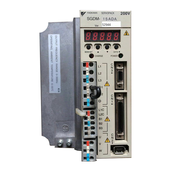
MODE/SET DATA/ Refer to 5.8.8 Absolute Encoder Battery, CHARGE POWER 8.4.3 Handing Batteries, and 8.4.4 Battery Replacement Procedure. Front cover YASKAWA SERVOPACK Panel display 5-digit, 7-segment LED used to display SGDM- SERVOPACK model YASKAWA SERVOPACK status, alarm status, and other Refer to 2.1 SERVOPACK Model... - Page 30 1.2 Product Part Names (2) SGDM for 6.0 kW to 15.0 kW Power indicator Panel operator Panel display SERVOPACK 200V SERVOPACK model SGDM- Ver. CN8 Battery connector YASKAWA POWER CN3 Connector for Battery holder personal computer monitoring and BATTERY MODE/SET DATA/...
-
Page 31: Examples Of Servo System Configurations
SGDM- Noise filter SERVOPACK Used to eliminate Magnetic external noise from the contactor power line. (Refer to 5.8.10.) Turns the servo YASKAWA 200V ON and OFF. SERVOPACK Install a surge SGDM- absorber. Digital (Refer to 5.8.11.) operator (Refer to 5.8.2.) -
Page 32: Three-Phase, 200 V Main Circuit
(Refer to 5.8.2.) Magnetic SERVOPACK contactor Turns the servo Connection cable ON and OFF. for digital operator Install a surge absorber. (Refer to 5.8.2.) YASKAWA 200V Personal computer SERVOPACK (Refer to SGDM- 5.8.11.) Connection cable for personal computer MODE/SET DATA/... -
Page 33: Connecting To Sgmcs Servomotor
OFF when overcurrent is detected. (Refer to 5.8.9.) SGDM- Noise filter SERVOPACK Used to eliminate external noise from the power line. (Refer to 5.8.10.) YASKAWA 200V SERVOP ACK SGDM- Digital Magnetic operator contactor (Refer to 5.8.2.) Turns the servo ON and OFF. -
Page 34: Applicable Standards
1.4 Applicable Standards 1.4 Applicable Standards Σ-II Series servo drives conform to the following overseas standards. 1.4.1 North American Safety Standards (UL, CSA) LISTED ∗1 ∗2 Model Certifications Standards (UL File No.) Standards CSA C22.2 UL508C(E147823) SERVOPACK • SGDM No.14 •... -
Page 35: Σ-Ii Series Sgdm Servopack Upgraded Functions
1 Outline 1.5 Σ-II Series SGDM SERVOPACK Upgraded Functions The following functions have been added or upgraded on the SGDM SERVOPACK with software version 32 or later. Refer to the following table for the added or improved functions for each model. Software Version Software Version Reference... - Page 36 SERVOPACK manufacture can be read with “SigmaWin+ *.” * SigmaWin+ is a Windows-compatible software tool used to set up and tune Yaskawa servo drives. SigmaWin+ can be downloaded from the e-mechatronics site (http://www.e-mechatronics.com/en). 1-13...
-
Page 37: Selections
Selections 2.1 Servomotor Model Designations - - - - - - - - - - - - - - - - - - - - - - - - - - - - - - 2-2 2.1.1 Model SGMAH (3000 min ) - - - - - - - - - - - - - - - - - - - - - - - - - - - - - - - - - - - - - - - - - - 2-2 2.1.2 Model SGMPH (3000 min ) - - - - - - - - - - - - - - - - - - - - - - - - - - - - - - - - - - - - - - - - - - 2-4... -
Page 38: Servomotor Model Designations
2 Selections 2.1.1 Model SGMAH (3000 min 2.1 Servomotor Model Designations This section explains how to check the servomotor model and ratings. The alphanumeric codes after SGM H indicate the specifications. 2.1.1 Model SGMAH (3000 min (1) Without Gears 1st + digits digit digit... - Page 39 2.1 Servomotor Model Designations (2) With Gears 1st + 10th digits digit digit digit digit digit digit digit digit SGMAH − 01 A A H 1 2 B 1st + 2nd digits: 10th digit: Connector 3rd digit: Voltage Rated Output A:200V,B:100V Code Specifications...
-
Page 40: Model Sgmph (3000 Min -1 )
2 Selections 2.1.2 Model SGMPH (3000 min 2.1.2 Model SGMPH (3000 min (1) Without Gears 1st + digits digit digit digit digit digit digit SGMPH − 02 A A A 2 1 8th digit: Connector 1st + 2nd digits: Code Specifications 3rd digit : Voltage... - Page 41 2.1 Servomotor Model Designations (2) With Gears 1st + 10th digit digit digit digit digit digit digit digit digits SGMPH − 01 A A H 1 2 B 1st + 2nd digit: 10th digit: Connector 3rd digit: Voltage Rated Output A:200V,B:100V Code Specifications...
- Page 42 2 Selections 2.1.3 Model SGMGH (1500 min 2.1.3 Model SGMGH (1500 min (1) Without Gears 1st + digits digit digit digit digit digit SGMGH −13 A C A 2 1 7th digit: Brake and Oil Seal 1st + 2nd digits: 3rd digit: Voltage Rated Output (kW) A:200V...
- Page 43 2.1 Servomotor Model Designations (2) With Gears 1st + digits digit digit digit digit digit digit digit SGMGH − 20 A A L 1 4 B 9th digit: Brake Code Specifications Without brake With 90-VDC brake With 24-VDC brake 6th digit: 8th digit: Shaft End Gear Type Code 1st + 2nd digits:...
-
Page 44: Model Sgmgh (1500 Min -1 )
2 Selections 2.1.4 Model SGMGH (1000 min 2.1.4 Model SGMGH (1000 min (1) Without Gears 1st + digits digit digit digit digit digit SGMGH − 12 A C B 2 1 1st + 2nd digits: 3rd digit: Voltage Rated Output 7th digit: Brake and Oil Seal A: 200V (kW) - Page 45 2.1 Servomotor Model Designations (2) With Gears 1st + digits digit digit digit digit digit digit digit SGMGH − 20 A B L 1 4 B 9th digit: Brake Code Specifications Without brake With 90-VDC brake With 24-VDC brake 6th digit: 8th digit: Shaft End Gear Type Code Code...
-
Page 46: Model Sgmsh (3000 Min -1 )
2 Selections 2.1.5 Model SGMSH (3000 min 2.1.5 Model SGMSH (3000 min (1) Without Gears 1st + digits digit digit digit digit digit SGMSH − 10 A C A 2 1 1st + 2nd digits: 3rd digit: Voltage Rated Output 7th digit: Brake and Oil Seal A:200V (kW) - Page 47 2.1 Servomotor Model Designations (2) With Gears 1st + digits digit digit digit digit digit digit digit SGMSH − 10 A A L 1 4 B 9th digit: Brake 1st + 2nd digits: Code Specifications 3rd digit: Voltage Rated Output A:200V (kW) Without brake...
-
Page 48: Model Sgmdh (2000 Min -1 )
2 Selections 2.1.6 Model SGMDH (2000 min 2.1.6 Model SGMDH (2000 min • SGMDH servomotors are provided with 90-VDC brakes as standard. (The seventh digit: B) • Servomotors with backlash gears are not available for the model SGMDH. 1st + digits digit digit... -
Page 49: Model Sgmcs
2.1 Servomotor Model Designations 2.1.7 Model SGMCS 1st + digits digit digit digit digit digit SGMCS − 02 B 3 C 1 1 SGMCS Direct-drive motor 1st + 2nd digits: 3rd digit: Servomotor Outer Diameter (mm) Rated Torque (N m) 7th digit: Brake Specifi- Code... -
Page 50: Servopack Model Designations
2 Selections 2.2 SERVOPACK Model Designations Select the SERVOPACK according to the applied servomotor. 1st + digits digit digit digit digit SGDM - 1st + 2nd digits: 6th digit: Option Rated Output of Applicable Servomotor (kW) Rated Output of Code Specificatioins Applicable Servomotor (kW) Code... -
Page 51: Σ-Ii Series Servopacks And Applicable Servomotors
2.3 Σ-II Series SERVOPACKs and Applicable Servomotors 2.3 Σ-II Series SERVOPACKs and Applicable Servomotors 2.3.1 SGDM SERVOPACKs and SGM H Servomotors Σ-II Series SGDM SERVOPACK Σ-II Series SGM H Servomotor Single-phase Single-phase Three-phase 100 VAC 200 VAC 200 VAC − A3 (30 W) A3BD, A3BDA A3AD, A3ADA... -
Page 52: Sgdm Servopacks And Sgmcs Servomotors
2 Selections 2.3.2 SGDM SERVOPACKs and SGMCS Servomotors 2.3.2 SGDM SERVOPACKs and SGMCS Servomotors The SGMCS Servomotor can be combined only with a SGDM SERVOPACK with software version 32 or later. Note that SGMCS Servomotor can’t be used with the SGDM- D and SGDM SERVOPACK with software version 31 or earlier. -
Page 53: Selecting Cables
2.4 Selecting Cables 2.4 Selecting Cables 2.4.1 Cables for SGMAH and SGMPH Servomotors Contact Yaskawa Controls. Co., Ltd. YASKAWA 200V SERVOPACK SGDM- MODE/SET DATA/ CHARGE POWER B3 3 2-17... - Page 54 2 Selections 2.4.1 Cables for SGMAH and SGMPH Servomotors Refer- Name Length Type Specifications ence JZSP-CMP00-03 JZSP-CMP00-05 SERVOPACK Servomotor Cable with connec- 5.4.1 10 m JZSP-CMP00-10 tors on both ends 15 m JZSP-CMP00-15 20 m JZSP-CMP00-20 JZSP-CMP03-03 SERVOPACK Servomotor JZSP-CMP03-05 Cable with loose 5.4.3 wire at encoder...
- Page 55 2.4 Selecting Cables Refer- Name Servomotor Model Length Type Specifications ence SGMAH JZSP-CMM00-03 200 V: 30 W to 750 W JZSP-CMM00-05 SERVOPACK Servomotor 100 V: 30 W to 200 W 5.1.1 10 m JZSP-CMM00-10 SGMPH 200 V:100 W to 750 W 15 m JZSP-CMM00-15 100 V: 100 W and...
-
Page 56: Cables For Sgmgh/Sgmsh/Sgmdh Servomotors
100 W to 750 W connector kit with brakes SGMPH JZSP-CMM9-4 1.5 kW * For servomotors with brakes, cut the brake leads for use. 2.4.2 Cables for SGMGH/SGMSH/SGMDH Servomotors Contact Yaskawa Controls. Co., Ltd. YASKAWA 200V SERVOPACK SGDM- MODE/SET DATA/ POWER... - Page 57 2.4 Selecting Cables Refer- Name Length Type Specifications ence JZSP-CMP03-03 JZSP-CMP03-05 SERVOPACK end Encoder end Cable with loose 5.4.4 10 m JZSP-CMP03-10 wires at encoder end 15 m JZSP-CMP03-15 20 m JZSP-CMP03-20 JZSP-CMP01-03 With an straight plug JZSP-CMP01-05 SERVOPACK end Encoder end 10 m JZSP-CMP01-10 15 m...
- Page 58 2 Selections 2.4.2 Cables for SGMGH/SGMSH/SGMDH Servomotors Refer- Name Length Type Specifications ence JZSP-CMP11-03 With a straight plug JZSP-CMP11-05 SERVOPACK Encoder 10 m JZSP-CMP11-10 15 m JZSP-CMP11-15 Flexible type 20 m JZSP-CMP11-20 cable with connectors on both JZSP-CMP12-03 With an L-shaped plug Encoder ends JZSP-CMP12-05...
-
Page 59: Cables For Sgmcs Servomotors
Servomotor cable main circuit cable View A Servomotor Encoder main circuit cable cable • Encoder cable extension from 20 m up to 50 m YASKAWA 200V SERVOP ACK SGDM- SGDM SERVOPACK MODE/SET DATA/ CHARGE POWER Relay encoder cable Servomotor extension *... - Page 60 2 Selections 2.4.3 Cables for SGMCS Servomotors Type Servomo- Refer- Name Length Flexible Specifications tor Model ence Standard type Type JZSP-CMP60-03 JZSP-CSP60-03 Applicable flange :1, 3 JZSP-CMP60-05 JZSP-CSP60-05 JZSP-CMP60-10 JZSP-CSP60-10 SERVOPACK end Encoder end 10 m JZSP-CMP60-15 JZSP-CSP60-15 15 m Cable with connectors on JZSP-CMP60-20 JZSP-CSP60-20...
- Page 61 2.4 Selecting Cables Type Servomo- Refer- Name Length Flexible Specifications tor Model ence Standard type Type JZSP-CMP19-30 30 m Wires and Wires and connectors for JZSP-CMP19-40 40 m 50 m max. Connectors relay encoder cable exten- 6.4.6 for Relay sions are available for as- Encoder sembly by the customer.
-
Page 62: Selecting Peripheral Devices
∗ JZSP-CMS00-3 Operator * Order your cable from Yaskawa Controls Co., Ltd. in the following cases. • When you need a longer cable than the one supplied with the digital operator. • When you need additional cables. • When you use the digital operator for the Σ-I series (model: JUSP-OP02A-1). - Page 63 2.5 Selecting Peripheral Devices Refer- Name Length Type Specifications ence D-Sub 25-pin (For PC98) SERVOPACK Personal JZSP-CMS01 computer end D-Sub 9-pin (For DOS/V) Personal SERVOPACK 5.8.1 JZSP-CMS02 Connection Cable for Personal computer end Computer Half-pitch 14-pin (For PC 98) Personal SERVOPACK JZSP-CMS03 computer end...
-
Page 64: Molded-Case Circuit Breaker And Fuse Capacity
2 Selections 2.5.2 Molded-case Circuit Breaker and Fuse Capacity 2.5.2 Molded-case Circuit Breaker and Fuse Capacity Current Capacity of the Molded-case Circuit Breaker SERVOPACK Model Inrush Current Main Power Supply *1, *2 and the Fuse (A Circuit Capacity per (Refer to 5.8.9) Power SERVOPACK Control Cir-... -
Page 65: Noise Filters, Magnetic Conductors, Surge Absorbers And Dc Reactors
FN, FS type: Schaffner Electronic Noise Filter FMAC type: SCHURTER (formerly Timonta AG) Magnetic Contactor Yaskawa Controls Co., Ltd. Yaskawa Controls Co., Ltd. (Sold as surge suppressor) Surge Absorber Okaya Electric Industries Co., Ltd. (Sold as surge protector) DC Reactor Yaskawa Controls Co., Ltd. -
Page 66: Regenerative Resistors And Brake Power Supply Units
Refer to 5.8.6 External Regenerative Resistor, 5.8.7 Regenerative Resistor Unit, and 6.5 Connecting Regen- erative Resistors. 2. The following table shows the manufacturers of each device. Peripheral Device Manufacturer External Regenerative Resistor Iwaki Wireless Research Institute External Regenerative Unit Yaskawa Electric Corporation Brake Power Supply Unit Yaskawa Controls Co., Ltd. 2-30... - Page 67 Servomotor Specifications and Dimensional Drawings 3.1 Ratings and Specifications of SGMAH (3000 min ) - - - - - - - - - - - - - - - - 3-4 3.1.1 SGMAH Servomotors Without Gears - - - - - - - - - - - - - - - - - - - - - - - - - - - - - - - - - - - 3-4 3.1.2 SGMAH Servomotors With Standard Backlash Gears - - - - - - - - - - - - - - - - - - - - - - - - 3-6 3.1.3 SGMAH Servomotors With Low-backlash Gears - - - - - - - - - - - - - - - - - - - - - - - - - - - 3-8 3.2 Ratings and Specifications of SGMPH (3000 min...
-
Page 68: Servomotor Specifications And Dimensional Drawings
3 Servomotor Specifications and Dimensional Drawings 3.9 Mechanical Specifications of SGMCS Servomotors - - - - - - - - - - - - - - - - 3-41 3.9.1 Allowable Loads - - - - - - - - - - - - - - - - - - - - - - - - - - - - - - - - - - - - - - - - - - - - - - - - - -3-41 3.9.2 Mechanical Tolerance - - - - - - - - - - - - - - - - - - - - - - - - - - - - - - - - - - - - - - - - - - - - - -3-42 3.9.3 Direction of Servomotor Rotation - - - - - - - - - - - - - - - - - - - - - - - - - - - - - - - - - - - - - -3-42 3.9.4 Impact Resistance - - - - - - - - - - - - - - - - - - - - - - - - - - - - - - - - - - - - - - - - - - - - - - - -3-43... - Page 69 3.17 Dimensional Drawings of SGMSH Servomotors (3000 min ) - - - - - - - 3-116 3.17.1 SGMSH Servomotors (3000 min ) Without Gears and Without Brakes - - - - - - - - 3-116 3.17.2 SGMSH Servomotors (3000 min ) 200-V Specifications Without Gears and With Brakes - - - - - - - - - - - - - - - - - - - - - - - - - - - - - - - - - - - - - - - - - - - - - - - 3-118 3.17.3 SGMSH Servomotors (3000 min...
-
Page 70: Ratings And Specifications Of Sgmah
3 Servomotor Specifications and Dimensional Drawings 3.1.1 SGMAH Servomotors Without Gears 3.1 Ratings and Specifications of SGMAH (3000 min 3.1.1 SGMAH Servomotors Without Gears (1) Ratings and Specifications • Time Rating: Continuous • Thermal Class: B • Vibration Class: 15 μm or below •... -
Page 71: Ratings And Specifications Of Sgmah
3.1 Ratings and Specifications of SGMAH (3000 min (2) Holding Brake Moment of Inertia The moment of inertia of the servomotor with holding brake is expressed using the following equation. (The moment of inertia of the servomotor with holding brake) = (rotor moment of inertia) + (brake moment of inertia) Servomotor Model SGMAH-... -
Page 72: Sgmah Servomotors With Standard Backlash Gears
3 Servomotor Specifications and Dimensional Drawings 3.1.2 SGMAH Servomotors With Standard Backlash Gears (5) Holding Brake Electrical Specifications Holding Brake Specifications Servomotor Holding Brake Servomotor Holding Coil Rated Capacity Capacity Rated Voltage Model Torque Resistance Current ° ° Ω (at 20 A (at 20 SGMAH-A3 0.0955... - Page 73 This may cause deterioration of the bearing or increase the load ratio. Contact your Yaskawa representative if you are using your servomotor under such conditions.
-
Page 74: Sgmah Servomotors With Low-Backlash Gears
3 Servomotor Specifications and Dimensional Drawings 3.1.3 SGMAH Servomotors With Low-backlash Gears 3.1.3 SGMAH Servomotors With Low-backlash Gears • Time Rating: Continuous • Thermal Class: B • Vibration Class: 15 μm or below • Withstand Voltage: 100V, 200V Servomotors: 1500 VAC for one minute •... - Page 75 This may cause deterioration of the bearing or increase the load ratio. Contact your Yaskawa representative if you are using your servomotor under such conditions.
-
Page 76: Ratings And Specifications Of Sgmph
3 Servomotor Specifications and Dimensional Drawings 3.2.1 SGMPH Servomotors Without Gears 3.2 Ratings and Specifications of SGMPH (3000 min 3.2.1 SGMPH Servomotors Without Gears (1) Ratings and Specifications • Time Rating: Continuous • Thermal Class: B • Vibration Class: 15 μm or below •... - Page 77 3.2 Ratings and Specifications of SGMPH (3000 min (2) Holding Brake Moment of Inertia The moment of inertia of the servomotor with holding brake is expressed using the following equation. (The moment of inertia of the servomotor with holding brake) = (rotor moment of inertia) + (brake moment inertia) Servomotor Model SGMPH-...
- Page 78 3 Servomotor Specifications and Dimensional Drawings 3.2.1 SGMPH Servomotors Without Gears (5) Holding Brake Electrical Specifications Holding Brake Specifications Holding Servomotor Servomotor Holding Coil Rated Brake Rated Capacity Capacity Model Torque Resistance Current Voltage N·m Ω (at 20 °C) A (at 20 °C) SGMPH-01 0.318 1000...
-
Page 79: Sgmph Servomotors With Standard Backlash Gears
This may cause deterioration of the bearing or increase the load ratio. Contact your Yaskawa representative if you are using your servomotor under such conditions. 3-13... -
Page 80: Sgmph Servomotors With Low-Backlash Gears
This may cause deterioration of the bearing or increase the load ratio. Contact your Yaskawa representative if you are using your servomotor under such conditions. 3-14... -
Page 81: Ratings And Specifications Of Sgmgh
3.3 Ratings and Specifications of SGMGH (1500 min 3.3 Ratings and Specifications of SGMGH (1500 min 3.3.1 SGMGH Servomotors (1500 min ) Without Gears (1) Ratings and Specifications • Time Rating: Continuous • Thermal Class: F • Vibration Class: 15 μm or below •... - Page 82 3 Servomotor Specifications and Dimensional Drawings 3.3.1 SGMGH Servomotors (1500 min ) Without Gears (2) Holding Brake Moment of Inertia The moment of inertia of the servomotor with holding brake is expressed using the following equation. (The moment of inertia of the servomotor with holding brake) = (rotor moment of inertia) + (brake moment of inertia) Servomotor Model 05A A 09A A 13A A 20A A 30A A 44A A 55A A 75A A...
-
Page 83: Ratings And Specifications Of Sgmgh
3.3 Ratings and Specifications of SGMGH (1500 min (4) Holding Brake Electrical Specifications Holding Brake Specifications Holding Servomotor Servomotor Holding Coil Rated Brake Rated Capacity Capacity Model Torque Resistance Current Voltage N·m Ω (at 20 °C) A (at 20 °C) SGMGH-05 10.1 4.41... - Page 84 ∗ Type 6130 to 6190: Oil * For oil lubrication, the motor should be mounted horizontal to the shaft. Contact your Yaskawa representative about lubrication for angle mounting. Note: Contact your Yaskawa representative regarding the use of servomotors in cases such as when the servomotor is frequently started and stopped, or when impact is generated on the gear output shaft by acceleration and deceleration.
- Page 85 3.3 Ratings and Specifications of SGMGH (1500 min (Cont’d) Moment of Inertia J Servomotor Gear Output ×10 kg·m Instanta- Servomotor Rated neous Model Rated Rated Max. Out- Rated Torque/ Gear Peak Motor + SGMGH- Speed Speed Speed Torque Gears Efficiency Ratio Torque/ Gears...
- Page 86 3 Servomotor Specifications and Dimensional Drawings 3.3.3 SGMGH Servomotors (1500 min ) With Low-backlash Gears 3.3.3 SGMGH Servomotors (1500 min ) With Low-backlash Gears • Time Rating: Continuous • Thermal Class: F • Vibration Class: 15 μm or below • Withstand Voltage: 200 V Servomotors: 1500 VAC for one minute •...
- Page 87 3.3 Ratings and Specifications of SGMGH (1500 min * Output torque and motor speed produce the following trends in efficiency. Values in the table are at the rated motor speed. Efficiency Efficiency Output torque Output torque Note: 1. For the shaft center allowable radial load, refer to the servomotor dimensional drawing. 2.
- Page 88 3 Servomotor Specifications and Dimensional Drawings 3.4.1 SGMGH Servomotors (1000 min ) Without Gears 3.4 Ratings and Specifications of SGMGH (1000 min 3.4.1 SGMGH Servomotors (1000 min ) Without Gears (1) Ratings and Specifications • Time Rating: Continuous • Thermal Class: F •...
- Page 89 3.4 Ratings and Specifications of SGMGH (1000 min (3) Torque-motor Speed Characteristics SGMGH-09A B SGMGH-12A B SGMGH-03A B SGMGH-06A B 2000 2000 2000 2000 1500 1500 1500 1500 Motor Motor Motor Motor speed speed speed speed 1000 1000 1000 1000 (min (min (min...
- Page 90 ∗ Type 6130 to 6190: Oil * For oil lubrication, the motor should be mounted horizontal to the shaft. Contact your Yaskawa representative about lubrication for angle mounting. Note: Contact your Yaskawa representative regarding the use of servomotors in cases such as when the servomotor is frequently started and stopped, or when impact is generated on the gear output shaft by acceleration and deceleration.
- Page 91 When using a servomotor with oil lubrication, the servomotor can be installed horizontally onto the shaft. Contact your Yaskawa representative for more information regarding the sliding installation of a servomotor. Note: 1. Output torque and motor speed produce the following trends in efficiency. Values in the table are at the rated motor speed.
- Page 92 3 Servomotor Specifications and Dimensional Drawings 3.4.3 SGMGH Servomotors (1000 min ) With Low-backlash Gears 3.4.3 SGMGH Servomotors (1000 min ) With Low-backlash Gears • Time Rating: Continuous • Thermal Class: F • Vibration Class: 15 μm or below • Withstand Voltage: 1500 VAC for one minute •...
-
Page 93: Ratings And Specifications Of Sgmsh
3.5 Ratings and Specifications of SGMSH (3000 min 3.5 Ratings and Specifications of SGMSH (3000 min 3.5.1 SGMSH Servomotors (3000 min ) Without Gears (1) Ratings and Specifications • Time Rating: Continuous • Thermal Class: F • Vibration Class: 15 μm or below •... - Page 94 3 Servomotor Specifications and Dimensional Drawings 3.5.1 SGMSH Servomotors (3000 min ) Without Gears (3) Torque-motor Speed Characteristics SGMSH-20A A SGMSH-30A A SGMSH-10A A SGMSH-15A A 5000 5000 5000 5000 4000 4000 4000 4000 3000 3000 3000 3000 Motor Motor Motor Motor speed...
- Page 95 3.5 Ratings and Specifications of SGMSH (3000 min 3.5.2 SGMSH Servomotors (3000 min ) With Low-backlash Gears • Time Rating: Continuous • Thermal Class: F • Vibration Class: 15 μm or below • Withstand Voltage: 1500 VAC for one minute •...
- Page 96 3 Servomotor Specifications and Dimensional Drawings 3.5.2 SGMSH Servomotors (3000 min ) With Low-backlash Gears * 1. The maximum input motor speed of the gears is 4000 min * 2. Output torque and motor speed produce the following trends in efficiency. Values in the table are at the rated motor speed.
-
Page 97: Ratings And Specifications Of Sgmdh
3.6 Ratings and Specifications of SGMDH (2000 min 3.6 Ratings and Specifications of SGMDH (2000 min 3.6.1 SGMDH Servomotors (2000 min ) With Holding Brakes (1) Ratings and Specifications • Time Rating: Continuous • Thermal Class: F • Vibration Class: 15 μm or below •... - Page 98 3 Servomotor Specifications and Dimensional Drawings 3.6.1 SGMDH Servomotors (2000 min ) With Holding Brakes (2) Torque-motor Speed Characteristics SGMDH-22A A B SGMDH-32A A B SGMDH-40A A B 3000 3000 3000 Motor 2000 Motor Motor 2000 : Continuous Duty Zone 2000 speed speed...
-
Page 99: Ratings And Specifications Of Sgmcs Servomotors
3.7 Ratings and Specifications of SGMCS Servomotors 3.7 Ratings and Specifications of SGMCS Servomotors 3.7.1 Small-capacity Series SGMCS Servomotors (1) Ratings and Specifications • Time Rating: Continuous • Thermal Class: A • Vibration Class: 15 μm or below • Withstand Voltage: 1500 VAC for one minute •... - Page 100 3 Servomotor Specifications and Dimensional Drawings 3.7.1 Small-capacity Series SGMCS Servomotors * 1. These items and torque-motor speed characteristics quoted in combination with an SGDM SERVOPACK are at an armature winding temperature of 100°C. Other values quoted at 20°C. All values are typical. * 2.
- Page 101 3.7 Ratings and Specifications of SGMCS Servomotors SGMCS-14C SGMCS-08D Motor speed Motor speed (min (min Torque (N m) Torque (N m) SGMCS-17D SGMCS-25D Motor speed Motor speed (min (min Torque (N m) Torque (N m) SGMCS-16E SGMCS-35E Motor speed Motor speed (min (min Torque (N m)
-
Page 102: Middle-Capacity Series Sgmcs Servomotors
3 Servomotor Specifications and Dimensional Drawings 3.7.2 Middle-capacity Series SGMCS Servomotors 3.7.2 Middle-capacity Series SGMCS Servomotors (1) Ratings and Specifications • Time Rating: Continuous • Thermal Class: F • Vibration Class: 15 μm or below • Withstand Voltage: 1500 VAC for one minute •... - Page 103 3.7 Ratings and Specifications of SGMCS Servomotors (2) Torque-Motor Speed Characteristics SGMCS-45M SGMCS-80M Motor speed Motor speed (min (min Torque(N m) Torque(N m) SGMCS-1AM SGMCS-80N Motor speed Motor speed (min (min Torque(N m) Torque(N m) SGMCS-1EN SGMCS-2ZN Motor speed Motor speed (min (min Torque(N m)
-
Page 104: Mechanical Specifications Of Sgmah, Sgmph, Sgmgh, Sgmsh, And Sgmdh Servomotors
3 Servomotor Specifications and Dimensional Drawings 3.8.1 Precautions on Servomotor Installation 3.8 Mechanical Specifications of SGMAH, SGMPH, SGMGH, SGMSH, and SGMDH Servomotors 3.8.1 Precautions on Servomotor Installation Servomotors can be installed either horizontally or vertically. The service life of the servomotor will be shortened or unexpected problems will occur if the servomotor is installed incorrectly or in an inappropriate location. -
Page 105: Mechanical Tolerance
3.8 Mechanical Specifications of SGMAH, SGMPH, SGMGH, SGMSH, and SGMDH Servomotors Make sure there are no bends or tension on the power lines. Cable Stress Especially be careful to wire signal line cables so that they are not subject to stress because the core wires are very thin at only 0.2 to 0.3 mm. -
Page 106: Impact Resistance
3 Servomotor Specifications and Dimensional Drawings 3.8.4 Impact Resistance 3.8.4 Impact Resistance Mount the servomotor with the axis horizontal. The servomotor will withstand the following vertical impacts: • Impact acceleration: 490 m/s • Impact occurrences: 2 Vertical 3.8.5 Vibration Resistance Mount the servomotor with the axis horizontal. -
Page 107: Mechanical Specifications Of Sgmcs Servomotors
3.9 Mechanical Specifications of SGMCS Servomotors 3.9 Mechanical Specifications of SGMCS Servomotors 3.9.1 Allowable Loads The loads applied while a servomotor is running are roughly classified in the following patterns. Design the machine so that the thrust load and moment load will not exceed the values in the table. Where F is external force, Thrust load: Fa = F + Load mass Moment load: M=0... -
Page 108: Mechanical Tolerance
3 Servomotor Specifications and Dimensional Drawings 3.9.2 Mechanical Tolerance 3.9.2 Mechanical Tolerance The following table shows tolerances for the servomotor’s output shaft and installation area. See the dimensional drawing of the individual servomotor for more details on tolerances. Mechanical Tolerance Tolerance T. -
Page 109: Impact Resistance
3.9 Mechanical Specifications of SGMCS Servomotors 3.9.4 Impact Resistance Mount the servomotor with the axis horizontal. The servomotor will withstand the following vertical impacts: Vertical • Impact Acceleration: 490 m/s • Number of Impacts: 2 Impact applied to the servomotor 3.9.5 Vibration Resistance Mount the servomotor with the axis horizontal. -
Page 110: Terms And Data For Servomotors With Gears
3 Servomotor Specifications and Dimensional Drawings 3.10 Terms and Data for Servomotors With Gears (1) Terms for Servomotors With Standard Backlash Gears and Low-backlash Gears Terminology for Servomotors with Gears Typical Value Standard Item Measurement Method/Definition Low-back- Backlash lash Gears Gears Rated Input Motor −... - Page 111 3.10 Terms and Data for Servomotors With Gears (3) Efficiency The output torque and motor speed produce the following trends in efficiency. The values in the tables, Ratings and Specifications of SGM H Servomotors with Gears, are at the rated motor torque and rated motor speed. Efficiency Efficiency Output torque...
-
Page 112: Servomotor Dimensional Drawings
3 Servomotor Specifications and Dimensional Drawings 3.11 Servomotor Dimensional Drawings Dimensional drawings for the SGM servomotors are broadly grouped using the following categories: With or without gears or brakes. Refer- Series Motor Capacity Groups of Servomotor Dimensional Drawings ence 3.12.1 Without gears and brakes 100 VAC: 3.12.2... -
Page 113: Dimensional Drawings Of Sgmah Servomotors
3.12 Dimensional Drawings of SGMAH Servomotors (3000 min 3.12 Dimensional Drawings of SGMAH Servomotors (3000 min 3.12.1 SGMAH Servomotors (3000 min ) Without Gears (1) 30 W, 50 W, 100 W Encoder cable, φ6 Encoder plug UL20276 300 ±30 Motor cable φ7 Motor plug Shaft End (35) - Page 114 3 Servomotor Specifications and Dimensional Drawings 3.12.1 SGMAH Servomotors (3000 min ) Without Gears • Dimensional Tolerances Units: mm Shaft-end Dimensions Model SGMAH- – 0.008 – 0.008 – 0.009 (2) 200 W, 400 W Units: mm Model SGMAH- 126.5 96.5 04A A21 154.5 124.5 04A A41...
- Page 115 3.12 Dimensional Drawings of SGMAH Servomotors (3000 min Units: mm Approx. Allowable Allowable Model Tap× Mass Radial Load Thrust Load SGMAH- Depth No key No tap M5×8L No key 04A A21 No tap 04A A41 M5×8L 04A A61 1. The dimensions for L and LL of a servomotor incorporating an encoder with super-capacitor (model: SGMAH- INFO 4) are as shown below.
- Page 116 3 Servomotor Specifications and Dimensional Drawings 3.12.2 SGMAH Servomotors (3000 min ) Without Gears and With Brakes 3.12.2 SGMAH Servomotors (3000 min ) Without Gears and With Brakes (1) 30 W, 50 W, 100 W 300 ±30 Shaft End (35) 300 ±30 0.04 φ0.04...
- Page 117 3.12 Dimensional Drawings of SGMAH Servomotors (3000 min • Dimensional Tolerances Units: mm Shaft-end Dimensions Model SGMAH- – 0.008 – 0.008 – 0.009 (2) 200 W, 400 W 300 ±30 (35) 300 ±30 0.04 26.5 φ0.04 Holding brake (de-energizing operation) Serial encoder Power supply: 90 VDC or 24 VDC 0.02...
- Page 118 3 Servomotor Specifications and Dimensional Drawings 3.12.2 SGMAH Servomotors (3000 min ) Without Gears and With Brakes Units: mm Approx. Allowable Allowable Model Tap× Mass Radial Load Thrust Load SGMAH- Depth No key No tap M5×8L No key 04A A2 No tap 04A A4 M5×8L...
- Page 119 3.12 Dimensional Drawings of SGMAH Servomotors (3000 min 3.12.3 SGMAH Servomotors (3000 min ) With Standard Backlash Gears (1) 30 W, 50 W, 100 W Encoder cable φ6 300 ±30 Encoder plug UL20276 Shaft End (35) Motor cable φ7 Motor plug 300±30 0.06 φ0.05...
- Page 120 3 Servomotor Specifications and Dimensional Drawings 3.12.3 SGMAH Servomotors (3000 min ) With Standard Backlash Gears 1. The dimensions for L and LL of a servomotor incorporating an encoder with super-capacitor (model: SGMAH- INFO 4) are as shown below. SGMAH-A3, A5, and 01: L-dimension +12 mm, LL-dimension +12 mm 2.
- Page 121 3.12 Dimensional Drawings of SGMAH Servomotors (3000 min (2) 200 W, 400 W, 750 W 300 ±30 Encoder cable φ7 Encoder plug Shaft End UL20276 Motor cable φ7 (35) Motor plug 0.04 300 ±30 0.06 φ0.05 26.5 4-φLZ Tap × Depth Rotating section Serial encoder Hatching section...
- Page 122 3 Servomotor Specifications and Dimensional Drawings 3.12.3 SGMAH Servomotors (3000 min ) With Standard Backlash Gears • Dimensional Tolerances Units: mm Flange Face Dimensions Shaft-end Dimensions Model SGMAH- AJ1 1 – 0.021 – 0.035 AJ3 1 – 0.035 – 0.021 AJC 1 –...
- Page 123 3.12 Dimensional Drawings of SGMAH Servomotors (3000 min 3.12.4 SGMAH Servomotors (3000 min ) With Standard Backlash Gears and Brakes (1) 30 W, 50 W, 100 W Encoder cable φ6 300±30 Encoder plug UL20276 Shaft End Motor cable φ7 (35) Motor plug 300±30 0.06...
- Page 124 3 Servomotor Specifications and Dimensional Drawings 3.12.4 SGMAH Servomotors (3000 min ) With Standard Backlash Gears and Brakes 1. The dimensionss for L and LL of a servomotor incorporating an encoder with super-capacitor (model: SGMAH- INFO 4) are as shown below. SGMAH-03, A5, and 01: L-dimension +12 mm, LL-dimension +12 mm 2.
- Page 125 3.12 Dimensional Drawings of SGMAH Servomotors (3000 min (2) 200 W, 400 W, 750 W 300 ±30 Encoder cable φ6 Encoder plug Shaft End UL20276 Motor cable φ7 (35) Motor plug 0.04 300 ±30 0.06 φ0.05 26.5 Tap × Depth 4-φLZ Holding brake (de-energizing operation) Rotating section...
- Page 126 3 Servomotor Specifications and Dimensional Drawings 3.12.4 SGMAH Servomotors (3000 min ) With Standard Backlash Gears and Brakes Units: mm Allowable Allowable Approx. Model Gear Radial Thrust × Mass Depth Ratio Load Load SGMAH- × × 3/31 × 1/21 × 1/33 ×...
- Page 127 3.12 Dimensional Drawings of SGMAH Servomotors (3000 min • Dimensional Tolerances Units: mm Flange Face Dimensions Shaft-end Dimensions Model SGMAH- – 0.035 – 0.021 – 0.035 – 0.021 – 0.021 – 0.035 – 0.035 – 0.021 – 0.035 – 0.021 –...
- Page 128 3 Servomotor Specifications and Dimensional Drawings 3.12.5 SGMAH Servomotors (3000 min ) With Low-backlash Gears 3.12.5 SGMAH Servomotors (3000 min ) With Low-backlash Gears (1) 30 W, 50 W, 100 W 300 ±30 Encoder cable φ6 Encoder plug UL20276 Motor cable (35) Shaft End φ7...
- Page 129 3.12 Dimensional Drawings of SGMAH Servomotors (3000 min Units: mm Allowable Allowable Approx. Gear Radial Thrust × Model SGMAH- Depth Mass Ratio Load Load 1/21 M5×10L AHC 1 AH7 1 1/33 M5×10L 1. The dimensions for L and LL of a servomotor incorporating an encoder with super-capacitor (model: SGMAH- INFO 4) are as shown below.
- Page 130 3 Servomotor Specifications and Dimensional Drawings 3.12.5 SGMAH Servomotors (3000 min ) With Low-backlash Gears (2) 200 W, 400 W, 750 W 300 ±30 Encoder cable φ7 Encoder plug Shaft End UL20276 (35) Motor cable Motor plug φ7 0.04 300±30 0.06 φ0.05 26.5...
- Page 131 3.12 Dimensional Drawings of SGMAH Servomotors (3000 min Units: mm Allowable Allowable Approx. Model Gear Radial Thrust × Depth Mass SGMAH- Ratio Load Load M5×10L AH1 1 1/11 M5×10L AHB 1 1/21 M6×12L AHC 1 1/33 M6×12L AH7 1 M5×10L AH1 1 1/11 M6×12L...
-
Page 132: Dimensional Drawings Of Sgmph Servomotors
3 Servomotor Specifications and Dimensional Drawings 3.13.1 SGMPH Servomotors (3000 min ) Without Gears and Brakes 3.13 Dimensional Drawings of SGMPH Servomotors (3000 min 3.13.1 SGMPH Servomotors (3000 min ) Without Gears and Brakes 300 ±30 Encoder plug Encoder cable φ5 Shaft End UL20276 (35) - Page 133 3.13 Dimensional Drawings of SGMPH Servomotors (3000 min Units: mm Approx. Allowable Allowable Model Mass Radial Load Thrust Load SGMPH- No key No key No key No key No key • Dimensional Tolerances Units: mm Shaft-end Dimensions Flange Face Dimensions Model SGMPH- –...
- Page 134 3 Servomotor Specifications and Dimensional Drawings 3.13.2 SGMPH Servomotors (3000 min ) With Brakes 3.13.2 SGMPH Servomotors (3000 min ) With Brakes Encoder plug 300 ±30 Encoder cable φ6 Shaft End UL20276 Motor cable φ7 (35) Motor plug 300 ±30 Dimensions of SGMPH-01 to 04 Dimensions of SGMPH-08 and -15 0.04 φ0.04...
- Page 135 3.13 Dimensional Drawings of SGMPH Servomotors (3000 min Units: mm Approx. Allowable Allowable Model Mass Radial Load Thrust Load SGMPH- No key No key No key No key No key • Dimensional Tolerances Units: mm Shaft-end Dimensions Flange Face Dimensions Model SGMPH- –...
-
Page 136: And Without Brakes
3 Servomotor Specifications and Dimensional Drawings 3.13.3 SGMPH Servomotors (3000 min ) With Standard Backlash Gears and Without Brakes 3.13.3 SGMPH Servomotors (3000 min ) With Standard Backlash Gears and Without Brakes 300 ±30 Encoder plug Shaft End Encoder cable φ6 UL20276 (35) Motor plug... - Page 137 3.13 Dimensional Drawings of SGMPH Servomotors (3000 min Units: mm Allowable Allowable Approx. Model Gear Radial Thrust × LC LA Depth Mass SGMPH- Ratio Load Load M4 × 8L 12.5 6.6 10.55 AJ1 1 M4 × 8L AJ3 1 3/31 12.5 6.6 10.55 1/21 90 105 12.5...
- Page 138 3 Servomotor Specifications and Dimensional Drawings 3.13.3 SGMPH Servomotors (3000 min ) With Standard Backlash Gears and Without Brakes • Dimensional Tolerances Units: mm Flange Face Dimensions Shaft-end Dimensions Model SGMPH- AJ1 1 – 0.011 – 0.030 AJ3 1 – 0.011 –...
- Page 139 3.13 Dimensional Drawings of SGMPH Servomotors (3000 min 3.13.4 SGMPH Servomotors (3000 min ) With Standard Backlash Gears and Brakes Encoder cable φ6 Encoder plug 300 ±30 UL20276 Motor cable φ7 (35) Shaft End Motor plug 300 ±30 0.06 0.04 φ0.05 4-φLZ Serial encoder...
- Page 140 3 Servomotor Specifications and Dimensional Drawings 3.13.4 SGMPH Servomotors (3000 min ) With Standard Backlash Gears and Brakes Units: mm Allowable Allowable Approx. Model Gear Radial Thrust × Mass Depth SGMPH- Ratio Load Load M4 × 8L 12.5 10.55 × 3/31 12.5 10.55...
- Page 141 3.13 Dimensional Drawings of SGMPH Servomotors (3000 min • Dimensional Tolerances Units: mm Flange Face Dimensions Shaft-end Dimensions Model SGMPH- – 0.030 – 0.018 – 0.018 – 0.030 – 0.035 – 0.021 – 0.035 – 0.021 – 0.035 – 0.021 –...
- Page 142 3 Servomotor Specifications and Dimensional Drawings 3.13.5 SGMPH Servomotors (3000 min ) With Low-backlash Gears 3.13.5 SGMPH Servomotors (3000 min ) With Low-backlash Gears 300 ±30 Encoder plug Encoder cable φ6 UL20276 Motor cable φ7 (35) Motor plug Shaft End 300 ±30 0.06 0.04...
- Page 143 3.13 Dimensional Drawings of SGMPH Servomotors (3000 min Units: mm Allowable Allowable Approx. Model Gear Radia Thrust × Mass Depth SGMPH- Ratio Load Load M4 × 8L 12.5 10.5 AH1 1 M4 × 8L 1/11 12.5 10.5 AHB 1 M5 × 10L 1/21 12.5 10.5...
- Page 144 3 Servomotor Specifications and Dimensional Drawings 3.13.5 SGMPH Servomotors (3000 min ) With Low-backlash Gears • Dimensional Tolerances Units: mm Flange Face Dimensions Shaft-end Dimensions Model SGMPH- AH1 1 – 0.018 – 0.030 AHB 1 – 0.018 – 0.030 AHC 1 –...
-
Page 145: Dimensional Drawing Of Output Shafts With Oil Seals For Sgmah And Sgmph Servomotors
3.14 Dimensional Drawing of Output Shafts With Oil Seals for SGMAH and SGMPH Servomotors 3.14 Dimensional Drawing of Output Shafts With Oil Seals for SGMAH and SGMPH Servomotors For the SGMAH and SGMPH servomotors with oil seals, the external dimensions of output shafts differ as shown below. -
Page 146: Servomotors
3 Servomotor Specifications and Dimensional Drawings 3.15.1 SGMGH Servomotors (1500 min ) Without Gears and Brakes 3.15 Dimensional Drawings of SGMGH Servomotors (1500 min 3.15.1 SGMGH Servomotors (1500 min ) Without Gears and Brakes Models with oil seals are of the same configuration. 0.04 * For 1A A to 1E... - Page 147 3.15 Dimensional Drawings of SGMGH Servomotors (1500 min Units: mm (Cont’d) Flange Face Dimensions Model SGMGH- 114.3 13.5 30A A21 – 0.025 114.3 13.5 44A A21 – 0.025 114.3 13.5 55A A21 – 0.025 114.3 13.5 75A A21 – 0.025 13.5 1AA A21 –...
-
Page 148: With Brakes
3 Servomotor Specifications and Dimensional Drawings 3.15.2 SGMGH Servomotors (1500 min ) 200-V Specifications Without Gears and With Brakes 3.15.2 SGMGH Servomotors (1500 min ) 200-V Specifications Without Gears and With Brakes (1) 450 W to 4.4 kW Models with oil seals are of the same configuration. Shaft End 0.04 SGMGH-05... - Page 149 3.15 Dimensional Drawings of SGMGH Servomotors (1500 min (2) 5.5kW to 15kW Models with oil seals are of the same configuration. * For 1A A to 1E A only Shaft End 0.04 0.06 φ0.04 4-φ13.5 Mounting holes 0.04 Note: For the specifications of the other shaft ends, refer to 3.20 Shaft End Specifications for SGMGH, SGMSH and SGMDH Servomotors.
- Page 150 3 Servomotor Specifications and Dimensional Drawings 3.15.3 SGMGH Servomotors (1500 min ) With Standard Backlash Gears and Without Brakes (Foot-mounted Type) 3.15.3 SGMGH Servomotors (1500 min ) With Standard Backlash Gears and With- out Brakes (Foot-mounted Type) (1) Grease Lubricating Type Shaft End Tap ×...
- Page 151 3.15 Dimensional Drawings of SGMGH Servomotors (1500 min Foot-mounted Dimensions Shaft-end Dimensions Approx. Model Gear Mass SGMGH- Ratio × Depth M8 × 20 180 135 20.7 05P AEA6 M8 × 20 1/11 180 135 20.7 05P AEB6 M8 × 20 1/21 180 135 22.7...
- Page 152 3 Servomotor Specifications and Dimensional Drawings 3.15.3 SGMGH Servomotors (1500 min ) With Standard Backlash Gears and Without Brakes (Foot-mounted Type) (2) Oil Lubricating Type Oil filler plug Oil drain plug Shaft End Tap × Depth (See the Oil drain following plug table.)
- Page 153 3.15 Dimensional Drawings of SGMGH Servomotors (1500 min Units: mm Foot-mounted Dimensions Shaft-end Dimensions Approx. Model Gear Mass SGMGH- Ratio × XR XC Depth × 1/29 145 145 330 195 14 M10 57.6 13P AE76 × 1/21 145 145 330 195 14 M10 20P AEC6 ×...
- Page 154 3 Servomotor Specifications and Dimensional Drawings 3.15.3 SGMGH Servomotors (1500 min ) With Standard Backlash Gears and Without Brakes (Foot-mounted Type) Units: mm (Cont’d) Shaft-end Dimensions Model SGMGH- 75P AEC6 – 0.019 75P AE76 – 0.019 1AP AEB6 – 0.019 1AP AEC6 –...
-
Page 155: Sgmgh Servomotors
3.15 Dimensional Drawings of SGMGH Servomotors (1500 min 3.15.4 SGMGH Servomotors (1500 min ) With Standard Backlash Gears and With- out Brakes (Flange-mounted Type) (1) Grease Lubricating Type Shaft End Tap × Depth (See the following table.) N-φ11 Mounting holes 4 Mounting holes 6 Mounting holes Units: mm... - Page 156 3 Servomotor Specifications and Dimensional Drawings 3.15.4 SGMGH Servomotors (1500 min ) With Standard Backlash Gears and Without Brakes (Flange-mounted Type) • Dimensional Tolerances Units: mm Flange Face Dimensions Shaft-end Dimensions Model SGMGH- – 0.036 05P AFA6 – 0.090 – 0.013 –...
- Page 157 3.15 Dimensional Drawings of SGMGH Servomotors (1500 min (2) Small Oil Lubricating Type Oil filler plug Oil drain plug Shaft End Tap × Depth 6-φ11 Mounting Oil drain plug holes -0.050 φ200f8: φ200 -0.122 φ50h6: φ50 -0.016 Units: mm Shaft Center Model Gear Allowable...
- Page 158 3 Servomotor Specifications and Dimensional Drawings 3.15.4 SGMGH Servomotors (1500 min ) With Standard Backlash Gears and Without Brakes (Flange-mounted Type) Lubrication INFO • Oil lubricating type (frame numbers: 6130 to 6190) Servomotors of this type have been shipped with oil removed. Be sure to supply oil until the red line at the upper side of the oil gauge.
- Page 159 3.15 Dimensional Drawings of SGMGH Servomotors (1500 min (3) Large Oil Lubricating Type Oil filler plug Shaft End Oil drain plug Tap × Depth (See the following table.) N-φLZ Mounting holes Oil drain plug Units: mm Shaft Center Model Gear Allowable Gear Model SGMGH-...
- Page 160 3 Servomotor Specifications and Dimensional Drawings 3.15.4 SGMGH Servomotors (1500 min ) With Standard Backlash Gears and Without Brakes (Flange-mounted Type) • Dimensional Tolerances Units: mm Flange Face Dimensions Shaft-end Dimensions Model SGMGH- – 0.056 30P AF76 – 0.137 – 0.019 –...
-
Page 161: Sgmgh Servomotors
3.15 Dimensional Drawings of SGMGH Servomotors (1500 min 3.15.5 SGMGH Servomotors (1500 min ) With Low-backlash Gears and Without Brakes (Flange-mounted Type) (1) Grease Lubricating Type for Small Applied Specifications of Shaft-end Tap d-tap×L Shaft End Units: mm d × L mm Frame No. - Page 162 3 Servomotor Specifications and Dimensional Drawings 3.15.5 SGMGH Servomotors (1500 min ) With Low-backlash Gears and Without Brakes (Flange-mounted Type) Units: mm Shaft Center Approx. Model Gear Gear Allowable Mass SGMGH- Model Ratio Radial Load 05A AL14 05A AL24 ANFJ-L20 09A AL14 09A AL24 Lubrication...
- Page 163 3.15 Dimensional Drawings of SGMGH Servomotors (1500 min Flange Face Dimensions Shaft-end Dimensions Approx. Model Gear Mass SGMGH- Ratio 1/20 05A AL54 1/29 05A AL74 1/45 05A AL84 1/20 09A AL54 1/29 09A AL74 1/45 09A AL84 13A AL14 13A AL24 1/20 13A AL54 1/29...
-
Page 164: Dimensional Drawings Of Sgmgh Servomotors
3 Servomotor Specifications and Dimensional Drawings 3.16.1 SGMGH Servomotors (1000 min ) Without Gears and Brakes 3.16 Dimensional Drawings of SGMGH Servomotors (1000 min 3.16.1 SGMGH Servomotors (1000 min ) Without Gears and Brakes Models with oil seals are of the same configuration. Shaft End SGMGH-03A B to 09A B SGMGH-12A B to 55A B... - Page 165 3.16 Dimensional Drawings of SGMGH Servomotors (1000 min Cable Specifications for Servomotor Cable Specifications for Detector Connectors (17-bit Encoder) Connectors Phase U Receptacle: MS3102A20-29P Phase V Applicable plug (Purchased by the customer) Phase W Plug: MS3108B20-29S Cable clamp: MS3057-12A (Frame ground) H G F With an Absolute Encoder With an Incremental Encoder...
- Page 166 3 Servomotor Specifications and Dimensional Drawings 3.16.2 SGMGH Servomotors (1000 min ) Without Gears and With Brakes 3.16.2 SGMGH Servomotors (1000 min ) Without Gears and With Brakes (1) 300 W to 3.0 kW Models with oil seals are of the same configuration. Shaft End 0.04 SGMGH-03A B to 09A B...
- Page 167 3.16 Dimensional Drawings of SGMGH Servomotors (1000 min Cable Specifications for Detector Connectors Cable Specifications for Servomotor Connectors (17-bit Encoder) Phase U Brake terminal Receptacle: MS3102A20-29P Phase V Brake terminal Applicable plug (Purchased by the customer) − Phase W Plug: MS3108B20-29S Cable clamp: MS3057-12A −...
- Page 168 3 Servomotor Specifications and Dimensional Drawings 3.16.2 SGMGH Servomotors (1000 min ) Without Gears and With Brakes (2) 4.0 kW to 5.5 kW Models with oil seals are of the same configuration. Shaft End 0.04 φ0.04 4-φ13.5 Mounting holes 0.04 Note: For the specifications of the other shaft ends, refer to 3.20 Shaft End Specifications for SGMGH, SGMSH and SGMDH Servomotors.
-
Page 169: With Standard Backlash Gears And
3.16 Dimensional Drawings of SGMGH Servomotors (1000 min 3.16.3 SGMGH Servomotors (1000 min ) With Standard Backlash Gears and With- out Brakes (Foot-mounted Type) (1) Grease Lubricating Type Shaft End Tap × Depth 4-φZ Mounting holes Units: mm Shaft Center Model Gear Gear... - Page 170 3 Servomotor Specifications and Dimensional Drawings 3.16.3 SGMGH Servomotors (1000 min ) With Standard Backlash Gears and Without Brakes (Foot-mounted Type) Foot-mounted Dimensions Shaft-end Dimensions Approx. Model Gear Mass SGMGH- Ratio × XR XC Depth × 180 135 20.7 03P BEA6 ×...
- Page 171 3.16 Dimensional Drawings of SGMGH Servomotors (1000 min • Dimensional Tolerances Units: mm Shaft-end Dimensions Model SGMGH- 03P BEA6 – 0.013 03P BEB6 – 0.013 03P BEC6 – 0.013 03P BE76 – 0.013 06P BEA6 – 0.013 06P BEB6 – 0.013 06P BEC6 –...
- Page 172 3 Servomotor Specifications and Dimensional Drawings 3.16.3 SGMGH Servomotors (1000 min ) With Standard Backlash Gears and Without Brakes (Foot-mounted Type) (2) Oil Lubricating Type Oil drain Oil filler plug plug Shaft End Tap × Depth Oil drain plug 4-φZ Mounting holes Units: mm Shaft Center...
- Page 173 3.16 Dimensional Drawings of SGMGH Servomotors (1000 min • Dimensional Tolerances Units: mm Shaft-end Dimensions Model SGMGH- 12P BEC6 – 0.016 12P BE76 – 0.016 20P BEC6 – 0.016 20P BE76 – 0.019 30P BEA6 – 0.016 30P BEB6 – 0.016 30P BEC6 –...
-
Page 174: With Standard Backlash Gears And
3 Servomotor Specifications and Dimensional Drawings 3.16.4 SGMGH Servomotors (1000 min ) With Standard Backlash Gears and Without Brakes (Flange-mounted Type) 3.16.4 SGMGH Servomotors (1000 min ) With Standard Backlash Gears and With- out Brakes (Flange-mounted Type) (1) Grease Lubricating Type 4 Mounting holes 6 Mounting holes Shaft End... - Page 175 3.16 Dimensional Drawings of SGMGH Servomotors (1000 min (Cont’d) Flange Face Dimensions Shaft-end Dimensions Approx. Model Mass SGMGH- × Depth × 12P BFA6 × 12P BFB6 × 20P BFA6 × 20P BFB6 • Dimensional Tolerances Units: mm Flange Face Dimensions Shaft-end Dimensions Model SGMGH-...
- Page 176 3 Servomotor Specifications and Dimensional Drawings 3.16.4 SGMGH Servomotors (1000 min ) With Standard Backlash Gears and Without Brakes (Flange-mounted Type) (2) Small Oil Lubricating Type Oil filler plug Shaft End Tap × Depth (See the following Oil drain plug table.) 6-φ11 Mounting holes Oil drain plug...
- Page 177 3.16 Dimensional Drawings of SGMGH Servomotors (1000 min (3) Large Oil Lubricating Type Oil drain plug Oil filler plug Shaft End Tap × Depth* N-φLZ Oil drain plug * See the following Mounting holes table. N-φLZ Mounting holes 6 Mounting holes 8 Mounting holes Units: mm Shaft Center...
- Page 178 3 Servomotor Specifications and Dimensional Drawings 3.16.4 SGMGH Servomotors (1000 min ) With Standard Backlash Gears and Without Brakes (Flange-mounted Type) • Dimensional Tolerances Units: mm Flange Face Dimensions Shaft-end Dimensions Model SGMGH- – 0.056 20P BF76 – 0.137 – 0.019 –...
-
Page 179: With Low-Backlash Gears And Without
3.16 Dimensional Drawings of SGMGH Servomotors (1000 min 3.16.5 SGMGH Servomotors (1000 min ) With Low-backlash Gears and Without Brakes (Flange-mounted Type) (1) Small Grease Lubricating Type Applied Specifications for Shaft-end Tap d-tap×L Shaft End Units: mm d × L mm Frame No. - Page 180 3 Servomotor Specifications and Dimensional Drawings 3.16.5 SGMGH Servomotors (1000 min ) With Low-backlash Gears and Without Brakes (Flange-mounted Type) Units: mm Shaft Center Approx. Model Gear Allowable Gear Type Mass SGMGH- Ratio Radial Load 03A BL14 03A BL24 1/20 1270 03A BL54 ANFJ-L20...
- Page 181 3.16 Dimensional Drawings of SGMGH Servomotors (1000 min Units: mm Shaft Center Model Gear Allowable Gear Model SGMGH- Ratio Radial Load 1/29 2940 03A BL74 1/45 3430 03A BL84 ANFJ-L30 1/20 2650 06A BL54 1/29 2940 06A BL74 1/45 8040 06A BL84 ANFJ-L40 1960...
- Page 182 3 Servomotor Specifications and Dimensional Drawings 3.17.1 SGMSH Servomotors (3000 min ) Without Gears and Without Brakes 3.17 Dimensional Drawings of SGMSH Servomotors (3000 min 3.17.1 SGMSH Servomotors (3000 min ) Without Gears and Without Brakes Models with oil seals are of the same configuration. Shaft End 0.04 φ0.04...
- Page 183 3.17 Dimensional Drawings of SGMSH Servomotors (3000 min Cable Specifications for Servomotor Cable Specifications for Detector Connectors Connectors (17-bit Encoder) Phase U Receptacle: MS3102A20-29P Phase V Applicable plug (Purchased by the customer) Phase W Plug: MS3108B20-29S Cale clamp: MS3057-12A (Frame ground) H G F With an Absolute Encoder With an Incremental Encoder...
- Page 184 3 Servomotor Specifications and Dimensional Drawings 3.17.2 SGMSH Servomotors (3000 min ) 200-V Specifications Without Gears and With Brakes 3.17.2 SGMSH Servomotors (3000 min ) 200-V Specifications Without Gears and With Brakes Models with oil seals are of the same configuration. Shaft End 0.04 φ0.04...
- Page 185 3.17 Dimensional Drawings of SGMSH Servomotors (3000 min Cable Specifications for Detector Connectors Cable Specifications for Servomotor Connectors (17-bit Encoder) Phase U Brake terminal Receptacle: MS3102A20-29P Phase V Brake terminal Applicable plug (Purchased by the customer) − Phase W Plug: MS3108B20-29S Cale clamp: MS3057-12A −...
- Page 186 3 Servomotor Specifications and Dimensional Drawings 3.17.3 SGMSH Servomotors (3000 min ) With Low-backlash Gears and Without Brakes (Flange-mounted Type) 3.17.3 SGMSH Servomotors (3000 min ) With Low-backlash Gears and Without Brakes (Flange-mounted Type) (1) Small Grease Lubricating Type Applied Specifications for Shaft-end Tap d-tap×L Shaft End Units: mm...
- Page 187 3.17 Dimensional Drawings of SGMSH Servomotors (3000 min Units: mm Shaft Center Approx. Model Gear Allowable Gear Model Mass SGMSH- Ratio Radial Load 10A AL14 10A AL24 ANFJ-L20 15A AL14 20A AL14 Lubrication INFO • Since grease has been filled prior to shipment, the servomotors can be used without replenishing grease. 3-121...
- Page 188 3 Servomotor Specifications and Dimensional Drawings 3.17.3 SGMSH Servomotors (3000 min ) With Low-backlash Gears and Without Brakes (Flange-mounted Type) (2) Large Grease Lubricating Type Shaft End 6-φLZ Mounting holes Units: mm Shaft Center Model Gear Allowable Gear Model SGMSH- Ratio Radial Load 1/20...
- Page 189 3.17 Dimensional Drawings of SGMSH Servomotors (3000 min Shaft-end Dimensions Approx. Flange Face Dimensions mm Model Gear Mass SGMSH- Ratio 1/20 10A AL54 1/29 10A AL74 1/45 10A AL84 15A AL24 1/20 15A AL54 1/29 15A AL74 1/45 15A AL84 20A AL24 1/20 20A AL54...
-
Page 190: Dimensional Drawings Of Sgmdh Servomotors
3 Servomotor Specifications and Dimensional Drawings 3.18.1 SGMDH Servomotors (2000 min ) Without Gears and With/Without Brakes 3.18 Dimensional Drawings of SGMDH Servomotors (2000 min These Servomotors are not provided with gears. 3.18.1 SGMDH Servomotors (2000 min ) Without Gears and With/Without Brakes Models with oil seals are of the same configuration. - Page 191 3.18 Dimensional Drawings of SGMDH Servomotors (2000 min Cable Specifications for Detector Connectors (17-bit Encoder) Receptacle: MS3102A20-29P Applicable plug (Purchased by the customer) Plug: MS3108B20-29S Cale clamp: MS3057-12A H G F With an Absolute Encoder With an Incremental Encoder − −...
-
Page 192: Sgmcs Servomotors Φ135 Model
3 Servomotor Specifications and Dimensional Drawings 3.19.1 SGMCS Servomotors φ135 Model 3.19 Dimensional Drawings of SGMCS Servomotors 3.19.1 SGMCS Servomotors φ135 Model (1) Applicable flange: 1 6 × M4 tapped, depth 8 6 × M4 tapped, depth 8 (Divided into six equal sections (Divided into six equal sections of sixty degrees) of sixty degrees) -
Page 193: Sgmcs Servomotors Φ175 Model
(0.5: Bolt section) ( 1 ) ( 9 ) × 60° M5 tapped, depth 8 0.04 Encoder-end Nameplate Servomotor-end (Only for use by Yaskawa) connector connector Nameplate φ130h7: φ130 Units: mm -0.040 φ160h7: φ160 -0.040 Model Approx. Mass (LL) -
Page 194: Sgmcs Servomotors Φ230 Model
(0.5: Bolt section) ( 1 ) ( 9 ) 60° 0.04 2 × M6 tapped, depth 10 Encoder-end Servomotor-end connector connector (Only for use by Yaskawa) Nameplate Nameplate -0.040 Units: mm -0.046 Model Approx. Mass (LL) SGMCS- 14.0 08D C11 22.0... -
Page 195: Sgmcs Servomotors Φ290 Model
0.08 (LL) 6±1.6 0.02 φ0.08 Rotating section (shown with hatching) Non- rotating section 2 × M8 tapped, depth 14 (Only for use by Yaskawa) 60° 0.04 Nameplate Servomotor-end Encoder-end connector connector Nameplate φ220h7: φ220 Units: mm -0.046 φ260h7: φ260 -0.052 Model Approx. -
Page 196: Sgmcs Servomotors Φ280 Model
3 Servomotor Specifications and Dimensional Drawings 3.19.5 SGMCS Servomotors φ280 Model 3.19.5 SGMCS Servomotors φ280 Model (1) Applicable flange: 1 12 × M6 screw, depth 15 (Divided into equal sections) 0.08 (within φ280h7) φ0.08 0.04 (Rotating Section) Rotating Section (shown with hatching) (within φ75H6) Rotating... -
Page 197: Sgmcs Servomotors Φ360 Model
3.19 Dimensional Drawings of SGMCS Servomotors 3.19.6 SGMCS Servomotors φ360 Model (1) Applicable flange: 1 12 × M8 screw, depth 15 Divided into equal sections 0.08 15 (within φ360h7) φ0.08 A B 0.04 (Rotating Section) Rotating Section (shown with hatching) Rotating (within φ118H6) Section... - Page 198 3 Servomotor Specifications and Dimensional Drawings 3.19.6 SGMCS Servomotors φ360 Model • Servomotor Connector for Small-capacity Series Servomotors Applicable Flange: 1, 3 Servomotor-end Connector Cable Specifications Model: JN1AS04MK2 Manufacturer: Japan Aviation Electronics Industry, Ltd. Applicable plug: JN1DS04FK1 (Provided by the customer.) Phase U Phase V Phase W...
- Page 199 3.19 Dimensional Drawings of SGMCS Servomotors • Servomotor-end Connector for Small-capacity Series Servomotors Applicable Flange: 4 Servomotor-end Connector Cable Specifications Model Plug: 350779-1 Pin: 350561-3 or 350690-3 (No.1 to 3) Ground pin: 350654-1 or 350669-1 (No.4) Manufacturer: Tyco Electronics AMP K.K. Applicable plug Cap: 350780-1 Socket: 350570-3 or 350689-3...
- Page 200 3 Servomotor Specifications and Dimensional Drawings 3.19.6 SGMCS Servomotors φ360 Model • Servomotor Connector for All Middle-capacity Series Servomotors Servomotor-end Connector Cable Specifications Model: CE05-2A18-10PD Manufacturer: DDK Ltd. Applicable plug and cable Plug: CE05-6A18-10SD-B-BSS Cable clamp: CE3057-10A-∗(D265) (Provided by the customer.) Phase U Phase V Phase W...
-
Page 201: Shaft End Specifications For Sgmgh, Sgmsh And Sgmdh Servomotors
3.20 Shaft End Specifications for SGMGH, SGMSH and SGMDH Servomotors 3.20 Shaft End Specifications for SGMGH, SGMSH and SGMDH Servomotors SGM H - Symbol Specifications Remarks Standard Straight, without key Taper 1/10, with parallel key Semi- (Key slot is JISB1301-1976 high precision. SGMGH standard series is interchangeable with USAGED series.) Taper 1/10, woodruff key... - Page 202 3 Servomotor Specifications and Dimensional Drawings 3.20.1 SGMGH Servomotors 3.20.1 SGMGH Servomotors Units: mm Model SGMGH- Symbol Specifications 03A B 06A B 09A B 12A B 20A B 30A B 40A B 55A B 1AA A 1EA A 05A A 09A A 13A A 20A A 30A A 44A A 55A A 75A A Straight +0.01 +0.030...
-
Page 203: Sgmsh Servomotors
3.20 Shaft End Specifications for SGMGH, SGMSH and SGMDH Servomotors 3.20.2 SGMSH Servomotors Units: mm Model Symbol Specifications SGMSH- Straight −0.013 −0.013 12.5 Taper 1/10, parallel key M12, P1.25 M16, P1.5 8.95 − − Taper 1/10, wood-ruff key −0.013 −0.013 Straight, with key and tap M8 screw, depth: 16 3-137... -
Page 204: Sgmdh Servomotors
3 Servomotor Specifications and Dimensional Drawings 3.20.3 SGMDH Servomotors 3.20.3 SGMDH Servomotors Units: mm Model Symbol Specifications SGMDH- Straight −0.013 −0.016 − − − − − − − − − − − − Taper 1/10, parallel key − − − −... - Page 205 SERVOPACK Specifications and Dimensional Drawings 4.1 SERVOPACK Ratings and Specifications - - - - - - - - - - - - - - - - - - - - - - - - 4-3 4.1.1 Single-phase 100 V - - - - - - - - - - - - - - - - - - - - - - - - - - - - - - - - - - - - - - - - - - - - - - - - 4-3 4.1.2 Single-phase/Three-phase 200 V - - - - - - - - - - - - - - - - - - - - - - - - - - - - - - - - - - - - - - 4-3 4.1.3 SERVOPACK Ratings and Specifications - - - - - - - - - - - - - - - - - - - - - - - - - - - - - - - - 4-4 4.2 SERVOPACK Installation - - - - - - - - - - - - - - - - - - - - - - - - - - - - - - - - - - - 4-6...
- Page 206 4 SERVOPACK Specifications and Dimensional Drawings 4.8 Dimensional Drawings of Rack-mounted SERVOPACK Model - - - - - - - - 4-24 4.8.1 Single-phase 100 V: 30 W/50 W/100 W (A3BD-R to 01BD-R, A3BDA-R to 01BDA-R) Single-phase 200 V: 30 W/50 W/100 W/200 W (A3AD-R to 02AD-R, A3ADA-R to 02ADA-R) - - - - - - - - - - - - - - - - - - - - - - - - - - - - - - - - - - - - - -4-24 4.8.2 Single-phase 100 V: 200 W (02BD-R, 02BDA-R) Single-phase 200 V: 400 W (04AD-R, 04ADA-R) - - - - - - - - - - - - - - - - - - - - - - - - - - -4-25...
- Page 207 4.1 SERVOPACK Ratings and Specifications 4.1 SERVOPACK Ratings and Specifications CAUTION • Take appropriate measures to ensure that the input power supply is supplied within the specified voltage range. An incorrect input power supply may result in damage to the SERVOPACK. If the voltage exceeds these values, use a step-down transformer so that the voltage will be within the specified range.
- Page 208 4 SERVOPACK Specifications and Dimensional Drawings 4.1.3 SERVOPACK Ratings and Specifications 4.1.3 SERVOPACK Ratings and Specifications Single or three-phase full-wave rectification IGBT-PWM (sine-wave Control Method driven) Serial encoder: 13, 16 or 17-bit (incremental/absolute) Basic Feedback ∗ The 13-bit encoder is incremental only. Specifi- ∗1 0 to +55 °C/-20 to +85 °C...
- Page 209 4.1 SERVOPACK Ratings and Specifications Dynamic Brake Operated at main power OFF, servo alarm, servo OFF or overtravel. Dynamic brake stop at P-OT or N-OT, deceleration to a stop, or coast to a Overtravel Stop stop 0.01 ≤ B/A ≤ 100 Electronic Gear Overcurrent, overvoltage, low voltage, overload, regeneration error, main Protection...
- Page 210 4 SERVOPACK Specifications and Dimensional Drawings 4.2 SERVOPACK Installation The SGDM SERVOPACKs can be mounted on a base, rack or duct-ventilated. Incorrect installation will cause problems. Always observe the following installation instructions. WARNING • After voltage resistance test, wait at least five minutes before servicing the product. (Refer to “Voltage Resis- tance Test”...
- Page 211 4.2 SERVOPACK Installation Install the SERVOPACK perpendicular to the wall as shown in the figure. The SERVOPACK must be oriented this way because it is designed to be cooled by natural convection or a cooling fan. Secure the SERVOPACK using two to four mounting holes. The number of holes depends on the capacity. Orientation Wall Ventilation...
- Page 212 4 SERVOPACK Specifications and Dimensional Drawings 4.3.1 Single-phase 200 V, 30 W to 400 W, and 100 V, 30 W to 200 W Models 4.3 SERVOPACK Internal Block Diagrams 4.3.1 Single-phase 200 V, 30 W to 400 W, and 100 V, 30 W to 200 W Models +10% Single-phase 200 to 230 V -15%...
- Page 213 4.3 SERVOPACK Internal Block Diagrams 4.3.3 Three-phase 200 V, 2.0 kW to 5.0 kW Models +10% Three-phase 200 to 230 V -15% (50/60 Hz) B1 B2 B3 FAN1 Servomotor Noise filter ±12 V CHARGE ~ ~ ~ Gate drive over- Relay Voltage Gate...
- Page 214 4 SERVOPACK Specifications and Dimensional Drawings 4.4 SERVOPACK’s Power Supply Capacities and Power Losses The following table shows SERVOPACK’s power supply capacities and power losses at the rated output. Table 4.1 SERVOPACK Power Losses at Rated Output Maximum Output Control Regenerative Total SERVOPACK...
- Page 215 4.5 SERVOPACK Overload Characteristics and Allowable Load Moment of Inertia 4.5 SERVOPACK Overload Characteristics and Allowable Load Moment of Inertia 4.5.1 Overload Characteristics SERVOPACKs have a built-in overload protective function that protects the SERVOPACKs and servomotors from overload. Allowable power for the SERVOPACKs is limited by the overload protective function as shown in the figure below.
- Page 216 • Reduce the deceleration rate. • Reduce the maximum motor speed. • Install an externally mounted regenerative resistor if the alarm cannot be cleared. Contact your Yaskawa Application Engineering Department. Regenerative resistors are not built into 200 V SERVOPACKs for 30 W to 400 W or 100 V SERVOPACKs for 30 W to 200 W.
- Page 217 4.5 SERVOPACK Overload Characteristics and Allowable Load Moment of Inertia (1) Allowable Load Moment of Inertia and Motor Speed for SGMAH 200 V Servomotors The following relationships between the motor speed and load moment of inertia are for an AC input power volt- age of 200 Vrms.
- Page 218 4 SERVOPACK Specifications and Dimensional Drawings 4.5.3 Load Moment of Inertia Allowable Load Moment of Inertia Servomotor Rated Output (N m) Model (Rotor Moment of Inertia Ratio) ×10 2.0, 4.0, 5.0, 7.0 × 5 10.0 × 3 8.0, 14.0, 16.0, 17.0, 25.0, 35.0 ×...
- Page 219 4.6 SERVOPACK Dimensional Drawings 4.6 SERVOPACK Dimensional Drawings SERVOPACK dimensional drawings are grouped according to the mounting method and the capacity. (1) Base-mounted Type SERVOPACK Supply Voltage Reference Capacity Model SGDM- D/DA 100 V 30 W / 50 W / 100 W A3B / A5B / 01B 4.7.1 200 V...
- Page 220 4.7 Dimensional Drawings of Base-mounted SERVOPACK Model 4.7.1 Single-phase 100 V: 30 W to 100 W (A3BD to 01BD, A3BDA to 01BDA) Single-phase 200 V: 30 W to 200 W (A3AD to 02AD, A3ADA to 02ADA) YASKAWA SERVOPACK SGDM- YASKAWA...
- Page 221 4.7 Dimensional Drawings of Base-mounted SERVOPACK Model 4.7.2 Single-phase 100 V: 200 W (02BD, 02BDA) Single-phase 200 V: 400 W (04AD, 04ADA) 2×φ5 holes YASKAWA SERVOPACK SGDM- YASKAWA Terminal MODE/SET DATA/ block CHARGE POWER Nameplate Ground terminal (75) (63) 2×M4 screws Units: mm Approx.
- Page 222 4 SERVOPACK Specifications and Dimensional Drawings 4.7.3 Three-phase 200 V: 500 W/750 W/1.0 kW (05AD to 10AD, 05ADA to 10ADA) 4.7.3 Three-phase 200 V: 500 W/750 W/1.0 kW (05AD to 10AD, 05ADA to 10ADA) φ5 hole 96.2 Terminal YASKAWA SERVOPACK200V SGDM- block YASKAWA MODE/SET DATA/...
- Page 223 4.7 Dimensional Drawings of Base-mounted SERVOPACK Model 4.7.4 Three-phase 200 V: 1.5 kW (15AD, 15ADA) 2×φ5 holes Heat sink YASKAWA SERVOPACK SGDM- YASKAWA MODE/SET DATA/ CHARGE POWER Terminal Ground block terminal Nameplate 100 ± 0.5 2×M4 screws (75) Units: mm Approx.
- Page 224 4 SERVOPACK Specifications and Dimensional Drawings 4.7.5 Three-phase 200 V: 2.0 kW/3.0 kW (20AD to 30AD, 20ADA to 30ADA) 4.7.5 Three-phase 200 V: 2.0 kW/3.0 kW (20AD to 30AD, 20ADA to 30ADA) 2×φ6 holes Heat sink YASKAWA SERVOPACK SGDM- YASKAWA MODE/SET DATA/...
- Page 225 4.7 Dimensional Drawings of Base-mounted SERVOPACK Model 4.7.6 Three-phase 200 V: 5.0 kW (50ADA) Heat sink 6-pin terminal M5 screw 4-pin terminal YASKAWA SERVOPACK M4 screw SGDM-50ADA Ver. MODE/SET DATA/ CHARGE POWER Nameplate 125±0.5 (75) 3-pin terminal Ground terminal M5 screw M5 screw (100°)
- Page 226 4 SERVOPACK Specifications and Dimensional Drawings 4.7.7 Three-phase 200 V: 6.0 kW/7.5 kW (60ADA to 75ADA) 4.7.7 Three-phase 200 V: 6.0 kW/7.5 kW (60ADA to 75ADA) Cooling fan SERVOPARK 200V SGDM- Ver. YASKAWA POWER BATTERY MODE/SET DATA/ Control circuit terminal...
- Page 227 4.7 Dimensional Drawings of Base-mounted SERVOPACK Model 4.7.8 Three-phase 200 V: 11.0 kW/15.0 kW (1AADA to 1EADA) Cooling fan SERVOPACK 200V SGDM- 1AADA Ver. YASKAWA POWER MODE/SET DATA/ BATTERY Control circuit terminal M4 Regenerative resistor terminal M6 Nameplate CHARGE L1C L2C...
- Page 228 4.8.1 Single-phase 100 V: 30 W/50 W/100 W (A3BD-R to 01BD-R, A3BDA-R to 01BDA-R) Single-phase 200 V: 30 W/50 W/100 W/200 W (A3AD-R to 02AD-R, A3ADA-R to 02ADA-R) (11.5) 24.5 (32.5) 22.5 φ 5 hole YASKAWA SERVOPACK SGDM- YASKAWA MODE/SET DATA/ CHANGE POWER Terminal block Nameplate (32.5)
- Page 229 4.8 Dimensional Drawings of Rack-mounted SERVOPACK Model 4.8.2 Single-phase 100 V: 200 W (02BD-R, 02BDA-R) Single-phase 200 V: 400 W (04AD-R, 04ADA-R) (11.5) 24.5 21.5 (32.5) 42.5 φ5 hole YASKAWA SERVOPACK SGDM- YASKAWA Terminal MODE/SET DATA/ block CHANGE POWER Nameplate (32.5)
- Page 230 4.8.3 Three-phase 200 V: 500 W/750 W/1.0 kW (05AD-R to 10AD-R, 05ADA-R to 10ADA-R) 25.5 (22.5) 24.5 φ 5 hole 46.5 43.5 96.2 Terminal block YASKAWA SERVOPACK200V SGDM- YASKAWA MODE/SET DATA/ CHANGE POWER Cooling fan Nameplate (75) Ground Mounting Hole Diagram terminal 2×M4 screws...
- Page 231 4.8 Dimensional Drawings of Rack-mounted SERVOPACK Model 4.8.4 Three-phase 200 V: 1.5 kW (15AD-R, 15ADA-R) Heat sink 4×M4 screw 2×φ5 holes Flange YASKAWA SERVOPACK SGDM- YASKAWA Terminal Nameplate block 24.5 (75) 50 ± 0.5 (48) (12) Flange Ground terminal 2×M4 screws Units: mm Approx.
- Page 232 4 SERVOPACK Specifications and Dimensional Drawings 4.8.5 Three-phase 200 V: 2.0 kW/3.0 kW (20AD-R to 30AD-R, 20ADA-R to 30ADA-R) 4.8.5 Three-phase 200 V: 2.0 kW/3.0 kW (20AD-R to 30AD-R, 20ADA-R to 30ADA-R) Heat sink Flange YASKAWA SERVOPACK SGDM- YASKAWA MODE/SET DATA/...
- Page 233 4.8 Dimensional Drawings of Rack-mounted SERVOPACK Model 4.8.6 Three-phase 200 V: 5.0 kW (50ADA-R) Flange Heat sink 6-pin terminal M5 screw YASKAWA SERVOPACK 200V SGDM-50ADA-R MODE/SET DATA/ CHANGE POWER 5-pin terminal M4 screw 3-pin terminal M5 screw Nameplate 24.5 (50)
- Page 234 4.9.1 Three-phase 200 V: 6.0 kW/7.5 kW (60ADA-P to 75ADA-P) 4.9 Dimensional Drawings of Duct-ventilated SERVOPACK Model 4.9.1 Three-phase 200 V: 6.0 kW/7.5 kW (60ADA-P to 75ADA-P) Cooling fan SERVOPACK 200V 2×φ6 SGDM- Ver. POWER holes YASKAWA BATTERY MODE/SET DATA/ Control circuit Control terminal M4 circuit Name- CHARGE...
- Page 235 4.9 Dimensional Drawings of Duct-ventilated SERVOPACK Model 4.9.2 Three-phase 200 V: 11.0 kW/15.0 kW (1AADA-P/1EADA-P) Externals Cooling fan SERVOPACK 200V SGDM- Ver. YASKAWA POWER MODE/SET DATA/ BATTERY Regenerative Resistor terminal Punched hole Control circuit Regenerative terminal M4 CHARGE resistor/ control circuit...
- Page 236 Specifications and Dimensional Drawings of Cables and Peripheral Devices 5.1 Specifications and Dimensional Drawings of Servomotor Main Circuit Cable - - - - - - - - - - - - - - - - - - - - - - - - - - - - - - - - - - - - - - - - - - - - 5-3 5.1.1 Cables for SGMAH and SGMPH Servomotors Without Brakes - - - - - - - - - - - - - - - - - 5-3 5.1.2 Cables for SGMAH and SGMPH Servomotors With Brakes - - - - - - - - - - - - - - - - - - - - 5-3 5.1.3 Flexible Cables for SGMAH and SGMPH Servomotors Without Brakes - - - - - - - - - - - 5-4...
- Page 237 5 Specifications and Dimensional Drawings of Cables and Peripheral Devices 5.4 Encoder Cables for CN2 Connector - - - - - - - - - - - - - - - - - - - - - - - - - - - 5-39 5.4.1 Encoder Cable With Connectors on Both Ends for SGMAH and SGMPH Servomotors 5-39 5.4.2 Encoder Cable With Connectors on Both Ends for SGMGH, SGMSH, and SGMDH Servomotors - - - - - - - - - - - - - - - - - - - - - - - - - - - - - - - - - - - - - - - - - - - - - - - - - - - -5-39...
- Page 238 5.1 Specifications and Dimensional Drawings of Servomotor Main Circuit Cable Contact Yaskawa Controls Co., Ltd. for SGMGH, SGMSH, and SGMDH Servomotor main circuit cables. When assembling the servomotor main circuit cable, refer to 5.2 Servomotor Main Circuit Wire Size and Connec- tors.
- Page 239 5 Specifications and Dimensional Drawings of Cables and Peripheral Devices 5.1.3 Flexible Cables for SGMAH and SGMPH Servomotors Without Brakes 5.1.3 Flexible Cables for SGMAH and SGMPH Servomotors Without Brakes SERVOPACK end Servomotor end Units: mm (10) Finished dimension φ6.5 Heat-shrinkable tube M4 crimped terminal...
- Page 240 5.1 Specifications and Dimensional Drawings of Servomotor Main Circuit Cable 5.1.5 Cables for SGMAH and SGMPH Servomotors With Waterproof Connector • For 30 W to 750 W SGMAH and 100 W to 750 W SGMPH Servomotors SERVOPACK end ∗ Servomotor end Units: mm Finished dimension φ6.5 Heat - shrinkable tube...
- Page 241 B, C, D, and E Servomotors 5.1.6 Cables for SGMCS- B, C, D, and E Servomotors Yaskawa provides cables only for SGMCS- B, C, D, and E servomotors. Cables for SGMCS- M, and N servomotors must be provided by the customer. Refer to 5.2.12 Connectors for SGMCS Servomotors.
- Page 242 5.2 Servomotor Main Circuit Wire Size and Connectors 5.2 Servomotor Main Circuit Wire Size and Connectors YASKAWA YASKAWA 200V 200V SERVOPACK SERVOPACK SGDM- SGDM- MODE/SET DATA/ MODE/SET DATA/ CHARGE POWER CHARGE POWER B3 3 B3 3 Encoder cable Encoder cable...
- Page 243 5 Specifications and Dimensional Drawings of Cables and Peripheral Devices 5.2.1 Wire Size (6) 200 V SGMDH Servomotors Rated Output 2.2 kW 3.2 kW 4.0 kW Three-phase HIV5.5 HIV8 200 V (7) 200 V SGMCS Servomotors Servomotor model 42 W 105 W 147 W 84 W...
- Page 244 5.2 Servomotor Main Circuit Wire Size and Connectors 5.2.2 SGMAH and SGMPH Servomotor Connectors for Standard Environments The SGMAH and SGMPH servomotors do not conform to the IEC’s IP67 classification (IP67 Protective Con- struction Standard) and the European Safety Standards. (1) 30 to 750 W SGMAH Servomotor Connector Kit Applicable Servomotor Models Type...
- Page 245 5 Specifications and Dimensional Drawings of Cables and Peripheral Devices 5.2.2 SGMAH and SGMPH Servomotor Connectors for Standard Environments (b) Connector Pin Arrangement Pin No. Signal Lead Color Remarks − Phase U − Phase V White − Phase W Blue Green/Yellow −...
- Page 246 5.2 Servomotor Main Circuit Wire Size and Connectors (7) SGMAH and SGMPH Servomotors With a Waterproof Connector (a) Connector Type: Refer to the table below. Applicable Servomotor Models Type Plug SPUC06KFSDN236 SGMAH 020.030.1020 30 W to 750 W Socket Soldered type SGMPH Interconnectron 100 W to 750 W...
- Page 247 Plug Waterproof straight plug Connector on Cable servomotor Waterproof cable clamp Waterproof L-shaped plug • Connector Manufacturers Contact Yaskawa Controls Co., Ltd. Connector Type Manufacturer Japan Aviation Electronics Plug Industry, Ltd. Cable clamp DDK Electronics, Inc. Nippon Flex Co., Ltd.
- Page 248 5.2 Servomotor Main Circuit Wire Size and Connectors 5.2.4 SGMGH Servomotor (1500 min ) Connectors for Standard Environments (1) Without Holding Brakes The specifications are same for both three-phase 200 V and 400 V servomotors. Plug Capacity Connector on Cable Clamp Servomotor (kW) Straight...
- Page 249 5 Specifications and Dimensional Drawings of Cables and Peripheral Devices 5.2.4 SGMGH Servomotor (1500 min ) Connectors for Standard Environments (b) Brake Power Supply Connectors 5.5 to 15.0 kW Servomotors Capacity (kW) Plug Connector on Three-phase Cable Clamp Servomotor Straight L-shaped 200 V Use the connector...
- Page 250 5.2 Servomotor Main Circuit Wire Size and Connectors 5.2.5 SGMGH Servomotor (1000 min ) Connectors for Standard Environments (1) Without Holding Brakes Plug Capacity Connector on Cable Clamp Servomotor (kW) Straight L-shaped MS3102A18-10P MS3106B18-10S MS3108B18-10S MS3057-10A MS3102A22-22P MS3106B22-22S MS3108B22-22S MS3057-12A MS3102A32-17P MS3106B32-17S MS3108B32-17S...
- Page 251 5 Specifications and Dimensional Drawings of Cables and Peripheral Devices 5.2.5 SGMGH Servomotor (1000 min ) Connectors for Standard Environments (3) SGMGH (1000 min ) Servomotor Main Circuit Connector Pin Arrangement (a) Without Holding Brakes 0.3 to 5.5 kW Servomotor Connector Pin Arrangement Pin No.
- Page 252 5.2 Servomotor Main Circuit Wire Size and Connectors 5.2.6 SGMSH Servomotor (3000 min ) Connectors for Standard Environments (1) Without Holding Brakes Plug Capacity Connector on Cable Clamp Servomotor (kW) Straight L-shaped MS3102A18-10P MS3106B18-10S MS3108B18-10S MS3057-10A MS3102A22-22P MS3106B22-22S MS3108B22-22S MS3057-12A (2) With Holding Brakes (a) Servomotor-end Connectors Plug...
- Page 253 5 Specifications and Dimensional Drawings of Cables and Peripheral Devices 5.2.6 SGMSH Servomotor (3000 min ) Connectors for Standard Environments (3) SGMSH Servomotor (3000 min ) Main Circuit Connector Pin Arrangement (a) Without Holding Brakes 1.0 to 5.0 kW Servomotor Connector Pin Arrangement Pin No.
- Page 254 5.2 Servomotor Main Circuit Wire Size and Connectors 5.2.7 SGMDH Servomotor (2000 min ) Connectors for Standard Environments (1) With and Without Holding Brakes Plug Capacity Connector on Cable Clamp (kW) Servomotor Straight L-shaped MS3102A24-10P MS3106B24-10S MS3108B24-10S MS3057-16A (2) Servomotor Main Circuit Connector Pin Arrangement Without Brakes With Brakes Pin No.
- Page 255 5 Specifications and Dimensional Drawings of Cables and Peripheral Devices 5.2.8 SGMGH Servomotor (1500 min ) Connectors Conforming to IP67 and European Safety Standards 5.2.8 SGMGH Servomotor (1500 min ) Connectors Conforming to IP67 and European Safety Standards (1) 0.45 to 4.4 kW Servomotors Without Holding Brakes Select a cable clamp in accordance with the applied cable diameter.
- Page 256 5.2 Servomotor Main Circuit Wire Size and Connectors (3) 0.45 to 4.4 kW Servomotors With Holding Brakes Select a cable clamp in accordance with the applied cable diameter. The straight plug type JA06A-24-10S-J1-EB and L-shaped plug type JA08A-24-10S-J1-EB conform to IP67 Protective INFO Construction Standard only.
- Page 257 5 Specifications and Dimensional Drawings of Cables and Peripheral Devices 5.2.8 SGMGH Servomotor (1500 min ) Connectors Conforming to IP67 and European Safety Standards (5) Servomotor Main Circuit Connector Pin Arrangement (a) Servomotors Without Holding Brakes 0.45 to 15.0 kW Servomotor Connector Pin Arrangement Pin No.
- Page 258 5.2 Servomotor Main Circuit Wire Size and Connectors 5.2.9 SGMGH Servomotor (1000 min ) Connectors Conforming to IP67 and European Safety Standards (1) Servomotors Without Holding Brakes (a) For 0.3 to 3.0 kW Servomotors Select a cable clamp in accordance with the applied cable diameter. The straight plug type JA06A-22-22S-J1-EB and L-shaped plug type JA08A-22-22S-J1-EB conform to IP67 Protective INFO Construction Standard only.
- Page 259 5 Specifications and Dimensional Drawings of Cables and Peripheral Devices 5.2.9 SGMGH Servomotor (1000 min ) Connectors Conforming to IP67 and European Safety Standards (2) 0.3 to 3.0 kW Servomotors With Holding Brakes Select a cable clamp in accordance with the applied cable diameter. The straight plug type JA06A-24-10S-J1-EB and L-shaped plug type JA08A-24-10S-J1-EB conform to IP67 Protective INFO Construction Standard only.
- Page 260 5.2 Servomotor Main Circuit Wire Size and Connectors (4) Servomotor Main Circuit Connector Pin Arrangement (a) Servomotors Without Holding Brakes 0.3 to 5.5 kW Servomotor Connector Pin Arrangement Pin No. Signal Phase U Phase V Phase W FG (Frame Ground) Servomotor-end connector (b) Servomotors With Holding Brakes...
- Page 261 5 Specifications and Dimensional Drawings of Cables and Peripheral Devices 5.2.10 SGMSH Servomotors (3000 min ) Connectors Conforming to IP67 and European Safety Standards 5.2.10 SGMSH Servomotors (3000 min ) Connectors Conforming to IP67 and European Safety Standards (1) Servomotors Without Holding Brakes Select a cable clamp in accordance with the applied cable diameter.
- Page 262 5.2 Servomotor Main Circuit Wire Size and Connectors (3) Servomotor Main Circuit Connector Pin Arrangement (a) Without Brakes 1.0 to 5.0 kW Servomotor Connector Pin Arrangement Pin No. Signal Phase U Phase V Phase W FG (Frame Ground) Servomotor-end connector (b) With Brakes 1.0 to 5.0 kW Servomotor Connector Pin Arrangement...
- Page 263 5 Specifications and Dimensional Drawings of Cables and Peripheral Devices 5.2.11 SGMDH Servomotors (2000 min ) Connectors Conforming to IP67 and European Safety Standards 5.2.11 SGMDH Servomotors (2000 min ) Connectors Conforming to IP67 and European Safety Standards (1) Servomotors With and Without Holding Brakes Select a cable clamp in accordance with the applied cable diameter.
- Page 264 Standard straight plug Non-waterproof Cable cable clamp Servomotor-end Standard L-shaped plug connector Servomotor end Cable end (Not provided by Yaskawa) Receptacle L-shaped plug Straight plug Cable clamp MS3102A18-10P MS3108B18-10S MS3106B18-10S MS3057-10A (b) MS3108B: L-shaped Plug Shell Dimensional Drawings Units: mm...
- Page 265 5 Specifications and Dimensional Drawings of Cables and Peripheral Devices 5.2.12 Connectors for SGMCS Servomotors (c) MS3106B: Straight Plug Shell Dimensional Drawings Units: mm Outer Length of Cable Effective Maxi- Diameter Joint Overall Joint Shell Clamp Set Screw of Joint Model Screw Length...
- Page 266 5.2 Servomotor Main Circuit Wire Size and Connectors 5.2.13 Connector Dimensional Drawings (1) Connectors Conforming to European Safety Standards (TÜV Certified), Manufactured by DDK Electronics, Inc. Contact Yaskawa Controls Co., Ltd. Plug (Waterproof when inserted only) Conduit Manufacturers Cable Nippon Flex Co., Ltd.
- Page 267 5 Specifications and Dimensional Drawings of Cables and Peripheral Devices 5.2.13 Connector Dimensional Drawings (c) L-shaped Plugs Positioning key V screw Units: mm Outer Max. Effective Diameter of Cable Clamp Joint Screw Overall Screw Model Mounting Screw R±0.7 U±0.7 (S)±1 Length Length φQ...
- Page 268 5.2 Servomotor Main Circuit Wire Size and Connectors (e) CE3057- A- (D265) Waterproof Cable Clamp With Rubber Bushing V screw (Cable clamp inner diameter) (Bushing inner diameter) (Movable range on one side) Units: mm Effective Overall Outer Applicable Screw Length Diameter Model G±0.7...
- Page 269 5 Specifications and Dimensional Drawings of Cables and Peripheral Devices 5.2.13 Connector Dimensional Drawings (2) Connectors Conforming to European Safety Standards (TÜV Certified), Manufactured by Japan Aviation Electronics Industry, Ltd. Contact Yaskawa Controls Co., Ltd. Plug Conduit (Waterproof when inserted only)
- Page 270 5.2 Servomotor Main Circuit Wire Size and Connectors (b) Straight Plugs Positioning key (Wrench width) (Effective screw length) V screw Units: mm Outer Diameter Cable Clamp Model of Nut φB±0.2 L±0.8 F±0.5 φG±0.5 Mounting Screw φQ±0.8 JL04V-6A20-15SE-EB 37.3 29.72 58.5 1-3/16-18UNEF-2A 40.5 30.05...
- Page 271 5 Specifications and Dimensional Drawings of Cables and Peripheral Devices 5.2.13 Connector Dimensional Drawings (d) Plugs Positioning key screw Conduit mounting dimensions Units: mm Outer Conduit Mounting Diameter Model φB±0.2 L±0.4 E max. Screw of Nut φQ±0.8 37.3 27.0 31.5 1-1/8-18UNEF-2A JL04V-6A20-15SE 40.5...
- Page 272 5.3 SERVOPACK Main Circuit Wire Size 5.3 SERVOPACK Main Circuit Wire Size 1. Wire sizes were selected for three cables per bundle at 40°C surrounding air temperature with the rated IMPORTANT current. 2. Use cable with a minimum withstand voltage of 600 V for main circuits. 3.
- Page 273 5 Specifications and Dimensional Drawings of Cables and Peripheral Devices 5.3.3 Single-phase 200 V 5.3.3 Single-phase 200 V SERVOPACK Model SGDM- Terminal External Terminal Name A3AD A5AD 01AD 02AD 04AD Symbol A3ADA A5ADA 01ADA 02ADA 04ADA HIV1.25 HIV2.0 Main circuit power supply input terminals L1, L2 HIV1.25 Servomotor connection terminals...
- Page 274 5.4 Encoder Cables for CN2 Connector When assembling the encoder cable, refer to 5.5 Connectors and Cables for Encoder Signals. Contact Yaskawa Controls Co., Ltd. for IP67 applicable cables, flexible cables and connectors. 5.4.1 Encoder Cable With Connectors on Both Ends for SGMAH and SGMPH...
- Page 275 5 Specifications and Dimensional Drawings of Cables and Peripheral Devices 5.4.3 Cable with Loose Wire at Encoder End for SGMAH and SGMPH Servomotors 5.4.3 Cable with Loose Wire at Encoder End for SGMAH and SGMPH Servomotors (1) Cable Type Cable Length Cable Type Dimensional Drawing JZSP-CMP03-03...
- Page 276 10 m JZSP-CMP03-10 15 m JZSP-CMP03-15 Crimped connector (Molex Japan Co., Ltd.) 20 m JZSP-CMP03-20 Wire markers (2) Encoder-end Connector Contact Yaskawa Controls Co., Ltd. Cable Cable Cable clamp Cable clamp Plug Cable Clamp Connector on (Manufactured by DDK Ltd.)
- Page 277 5 Specifications and Dimensional Drawings of Cables and Peripheral Devices 5.4.4 Cable with Loose Wire at Encoder End for SGMGH, SGMSH, and SGMDH Servomotors (3) Encoder Plug Connector Pin Arrangement H G F 17-bit Absolute Encoder Connection Specifications 17-bit Incremental Encoder Connection Specifications Wire Lead Wire...
- Page 278 5.4 Encoder Cables for CN2 Connector 5.4.5 Encoder Flexible Cables for SGMAH and SGMPH Servomotors (1) Flexible Cable With Connectors on Both Ends Cable Length Cable Type Dimensional Drawing JZSP-CMP10-03 SERVOPACK end Encoder end JZSP-CMP10-05 Finished dimension φ6.8 mm 10 m JZSP-CMP10-10 15 m JZSP-CMP10-15...
- Page 279 5 Specifications and Dimensional Drawings of Cables and Peripheral Devices 5.4.5 Encoder Flexible Cables for SGMAH and SGMPH Servomotors (c) Encoder Plug Connector Pin Arrangement lug: JZS -CM 9-1 (SERVO ACK end) Socket: JZS -CM 9-2 (Encoder end) 16-bit Serial Absolute Encoder Connection 13-bit Serial Incremental Encoder Connection Specifications Specifications...
- Page 280 φ6.8 mm 15 m JZSP-CMP13-15 Heat-shrinkable tube Wire markers Crimped connector 20 m JZSP-CMP13-20 (Molex Japan Co., Ltd.) (b) Encoder-end Connector Contact Yaskawa Controls Co., Ltd. Cable Cable clamp Cable clamp Cable Plug Cable Clamp Connector on (Manufactured by DDK Ltd.)
- Page 281 5 Specifications and Dimensional Drawings of Cables and Peripheral Devices 5.4.6 Encoder Flexible Cables for SGMGH, SGMSH, and SGMDH Servomotors (c) Encoder Plug Connector Pin Arrangement H G F 17-bit Absolute Encoder Connection Specifications 17-bit Incremental Encoder Connection Specifications Wire Lead Wire Lead...
- Page 282 5.4 Encoder Cables for CN2 Connector 5.4.7 Encoder Cable With a Waterproof Connector for SGMAH and SGMPH Servomotors (1) Cable Type Cable Type Length (L) Dimensional Drawing DP9325256-1 SERVOPACK end Servomotor end DP9325256-2 Finished dimension 10 m DP9325256-3 φ6.5 mm 15 m DP9325256-4 Soldered connector...
- Page 283 5 Specifications and Dimensional Drawings of Cables and Peripheral Devices 5.4.8 Encoder Cables for SGMCS Servomotors 5.4.8 Encoder Cables for SGMCS Servomotors If you use cables with loose leads or manufacture the cables, connect the shield wire of the encoder cable to the connector frame ground.
- Page 284 5.4 Encoder Cables for CN2 Connector (3) Cable with Loose Wire at Encoder End (a) Cable Type Standard Type Flexible Type Length (L) Dimensional Drawing JZSP-CMP03-03 JZSP-CMP13-03 SERVOPACK end Encoder end 60mm JZSP-CMP03-05 JZSP-CMP13-05 JZSP-CMP03-10 JZSP-CMP13-10 10 m JZSP-CMP03-15 JZSP-CMP13-15 15 m Plug connector Wire...
- Page 285 5.5.1 Connectors and Cables for SGMAH and SGMPH Servomotors 5.5 Connectors and Cables for Encoder Signals The IP67 applicable cables, flexible cables and connectors are options. Contact Yaskawa Controls Co., Ltd. 5.5.1 Connectors and Cables for SGMAH and SGMPH Servomotors...
- Page 286 Orange/ Light blue/ Lead Colors White White Orange Orange/ White Yaskawa Standard 5 m, 10 m, 15 m, 20 m 30 m, 40 m, 50 m Specifications (Standard Length) (5) Encoder Plug Connector Pin Arrangement 16-bit Serial Absolute Encoder 13-bit Serial Incremental Encoder...
- Page 287 5 Specifications and Dimensional Drawings of Cables and Peripheral Devices 5.5.2 Connectors and Cables for SGMGH, SGMSH, and SGMDH Servomotors 5.5.2 Connectors and Cables for SGMGH, SGMSH, and SGMDH Servomotors (1) Cable Type Cables for Maximum 20 m Cables for Maximum 50 m Wiring Distance Wiring Distance Cable Type...
- Page 288 Light blue/ Orange/ Lead Colors Orange White White Orange/ White Yaskawa Stan- dard Specifica- 5 m, 10 m, 15 m, 20 m 30 m, 40 m, 50 m tions (Standard Length) (5) Encoder Plug Connector Pin Arrangement H G F...
- Page 289 Black Orange Green Black/ Orange Pink Orange/ Red/ White Pink Cable length: 5 m, 10 m, 15 m, 20 m Yaskawa Standard Specifications (Standard Length) * Specify the cable length in of cable type designation. Example: JZSP-CMP09-05 (5 m) 5-54...
- Page 290 5.6 Flexible Cables 5.6 Flexible Cables (1) Life of Flexible Cable The flexible cable supports 10,000,000 or more operations of bending life with the recommended bending radius R = 90 mm under the following test conditions. • Conditions 1. Repeat moving one end of the cable forward and backward for 320 mm with using the test equipment shown in the following.
- Page 291 5 Specifications and Dimensional Drawings of Cables and Peripheral Devices 5.7.1 Standard Cables 5.7 I/O Signal Cables for CN1 Connector 5.7.1 Standard Cables For the connection diagram, refer to 5.7.3 Connection Diagram. (1) Cable Types Cable Type Cable Length (L) JZSP-CKI01-1 JZSP-CKI01-2 JZSP-CKI01-3...
- Page 292 5.7 I/O Signal Cables for CN1 Connector (2) Dimensional Drawing of Connector Units: mm 2.54 1.27 41.1 Pin No. 2 Pin No. 1 1.27 Pin No. 26 30.48 36.7 (3) Cable Size Item Specifications Cable Use twisted-pair or twisted-pair shielded wire. Applicable Wires AWG24, 26, 28, 30 φ16 mm or less...
- Page 293 5 Specifications and Dimensional Drawings of Cables and Peripheral Devices 5.7.3 Connection Diagram 5.7.3 Connection Diagram Host controller end SERVOPACK end Marking Lead Lead Pin No. Signal Color Marker No. Color Dots Orange Gray Orange Black Gray Black V-REF White White Black PULS...
- Page 294 5.8 Peripheral Devices 5.8 Peripheral Devices 5.8.1 Cables for Connecting Personal Computers (1) For 25-pin Connector Cable for NEC PC-98 Series PC (a) Cable Type: JZSP-CMS01 (b) Dimensional Drawing Units: mm Personal computer end SERVOPACK end Half-pitch connector Personal computer end SERVOPACK end D-sub connector (25-pin) Plug: 10114-3000VE...
- Page 295 29.5 (3) Other Types of the Applicable Connection Cables: JZSP-CMS00- Order your cable from Yaskawa Controls Co., Ltd. in the following cases. • When you need a longer cable than the one supplied with the digital operator. • When you need additional cables.
- Page 296 5.8 Peripheral Devices 5.8.3 Cables for Analog Monitor (1) Cable Type: JZSP-CA01 (DE9404559) Connect the specified cables to CN5 connector for monitoring the analog monitor signals. For details, refer to 9.5 Analog Monitor. With the front cover open Cable for Analog Monitor MODE/SET DATA/ CHARGE...
- Page 297 5.8.4 Connector Terminal Block Converter Unit 5.8.4 Connector Terminal Block Converter Unit (1) Model: JUSP-TA50P The connection between the connector terminal block converter and the SERVOPACK is shown below. YASKAWA SERVOPACK Attached cable length: 500 Connector terminal block converter unit...
- Page 298 5.8 Peripheral Devices 5.8.5 Brake Power Supply Unit LPSE-2H01, LPDE-1H01 (1) Model: Manufactured by Yaskawa Controls Co., Ltd. • 200 V input: LPSE-2H01 • 100 V input: LPDE-1H01 (2) Specifications • Rated output voltage: 90 VDC • Maximum output current: 1.0 ADC •...
- Page 299 5 Specifications and Dimensional Drawings of Cables and Peripheral Devices 5.8.5 Brake Power Supply Unit (b) Internal Circuit for 100 VAC Brake Power Supply Model: LPDE-1H01 Diode bridge Blue Surge DC (Brake) side Surge AC side absorber No polarity absorber 90 to 120 V White Black...
- Page 300 5.8 Peripheral Devices 5.8.6 External Regenerative Resistor Regenerative resistors for SERVOPACKs are internally or externally mounted as shown in the table below. Regenerative resistors can be externally mounted on all SERVOPACKs. Connect an external regenerative resis- tor to the SERVOPACK if regenerative energy exceeds the capacity of the SERVOPACK. If a regenerative resistor is to be mounted externally, the jumper between B2 and B3 for the internal regenerative resistor must be removed.
- Page 301 5 Specifications and Dimensional Drawings of Cables and Peripheral Devices 5.8.6 External Regenerative Resistor The external regenerative resistor must be purchased by customers. Refer to the table below for selecting an external regenerative resistor. Refer to 6.5 Connecting Regenerative Resistors for the connection. (1) References for External Regenerative Resistor Regenerative Specifications...
- Page 302 5.8 Peripheral Devices (4) Dimensional Drawings RH120/150/220 RH220B Units: mm Units: mm φ4.5 × φ4.5 Lead wire length L: 300 Lead wire length L: 500 Model Resistance Rated Power Dimensions Rated power: 120 W 1 to 100 Ω Resistance: 1 to100 Ω RH120 182 150 172 16 42 22 20 RH120...
- Page 303 5 Specifications and Dimensional Drawings of Cables and Peripheral Devices 5.8.7 Regenerative Resistor Unit 5.8.7 Regenerative Resistor Unit (1) Models The SERVOPACKs with a capacity of 6.0 kW or more do not have a built-in regenerative resistor. The following regenerative resistor unit is required according to the SERVOPACK model. Regenerative Resistor Allowable SERVOPACK Model...
- Page 304 5.8 Peripheral Devices 5.8.8 Absolute Encoder Battery When using an absolute encoder, a backup battery is required to prevent the position data from being lost at power OFF. Install one of the following absolute encoder batteries. There are two types of battery: Battery to be mounted on the SERVOPACK and battery to be connected to the host controller.
- Page 305 5 Specifications and Dimensional Drawings of Cables and Peripheral Devices 5.8.9 Molded-case Circuit Breaker (MCCB) 5.8.9 Molded-case Circuit Breaker (MCCB) If selecting a molded-case circuit breaker, observe the following precautions. Circuit Breakers IMPORTANT • Select a breaker for inverters. • High-frequency current leaks from the servomotor armature because of switching operations inside the SERVOPACK.
- Page 306 The noise filters model FN and FS manufactured by Schaffner Electronic and FMAC manufacture by Timonta AG are recommended. Contact Yaskawa Controls Co., Ltd. Select one of the following noise filters according to SERVOPACK capacity. For more details, refer to 2.5.3 Noise Filters, Magnetic Conductors, Surge Absorbers and DC Reactors.
- Page 307 5 Specifications and Dimensional Drawings of Cables and Peripheral Devices 5.8.10 Noise Filter (2) Three-phase, 200 V Select one of the following noise filters according to SERVOPACK capacity. For more details, refer to 2.5.3 Noise Filters, Magnetic Conductors, Surge Absorbers and DC Reactors. Refer to 6.1.3 Typical Main Circuit Wiring Examples for the connection method.
- Page 308 5.8 Peripheral Devices (b) FMAC Series Model FMAC-0934-5010 FMAC-0953-6410 Dimensional Drawings Symbol Dimensions – – 1 – 1 – External 6.5±0.3 6.5±0.3 Dimensions 115±0.3 115±0.3 in mm (10) (13) (41) (45) (17) (34) 440 VAC, 50 A 440 VAC, 64 A Specifications Applicable Three-...
- Page 309 5 Specifications and Dimensional Drawings of Cables and Peripheral Devices 5.8.10 Noise Filter (c) FS Series Model FS5559-35-33 FS5559-80-34 FS5559-150-35 Dimensional Drawings SCHAFFNER Symbol Dimensions External Dimensions in mm 480 V, 35 A 480 V, 80 A 480 V, 150 A Specifications Applicable Three-...
- Page 310 HI- J (1) Model: The magnetic contactor is manufactured by Yaskawa Controls Co., Ltd. A magnetic contactor is required to make the AC power supply to SERVOPACK ON/OFF sequence externally. Be sure to attach a surge absorber to the excitation coil of the magnetic contactor. Refer to 5.8.12 Surge Absorber (for switching surge) for details of the surge absorber.
- Page 311 5 Specifications and Dimensional Drawings of Cables and Peripheral Devices 5.8.11 Magnetic Contactor (c) Model: HI-25J and HI-35J Mounting Hole Dimensions in mm Terminal Symbols Dimensions in mm Approx. mass: 0.68 kg M3.5 Coil 23.4 terminal Auxiliary Structure contact 1NO1NC 12.2 M3.5 Auxiliary 2 ×...
- Page 312 5.8 Peripheral Devices 5.8.12 Surge Absorber (for switching surge) (1) Surge Absorber for Magnetic Contactor Contact Yaskawa Controls Co., Ltd. (a) Model: TU-25 , TU-65 (Sold as Surge Suppressor) (b) Specifications Applicable Voltage Range for Operation Rated Magnetic Coil Surge...
- Page 313 5 Specifications and Dimensional Drawings of Cables and Peripheral Devices 5.8.12 Surge Absorber (for switching surge) (2) Surge Absorber for Brake Power Supply When using a servomotor with holding brake, install a surge absorber near the brake coil to prevent the power supply noises.
- Page 314 5.8 Peripheral Devices 5.8.13 Surge Absorber (for lightning surge) R C M-601BQZ-4 and R C M-601BUZ-4 (Sold as Surge Protector) (1) Model: Manufactured by Okaya Electric Industries Co., Ltd. The surge absorber absorbs lightning surge and prevents faulty operation in or damage to electronic circuits. Recommended surge absorbers are listed below.
- Page 315 5.8.14 DC Reactor for Harmonic Suppression (1) Specifications DC reactor for harmonic suppression is handled by Yaskawa Controls Co., Ltd. If necessary for harmonic suppression, connect a DC reactor to the SERVOPACK. Note that no terminal for con- necting a DC reactor is provided to the 6.0 kW or more SERVOPACKs.
- Page 316 5.8.15 Variable Resistor for Speed and Torque Setting : 25HP-10B (1) Model The multiturn type winding variable resistors with dial MD10-30B4 are manufactured by Sakae Tsushin Kogyo Co., Ltd. Contact Yaskawa Controls Co., Ltd. (2) Dimensional Drawings Units: mm Panel 11.5±1...
- Page 317 The encoder signal converter unit (the trade name “Receiver Unit”) converts encoder signal output from the line driver to open-collector or voltage-pulse output. A socket model 11PFA is required to use a Receiver Unit. (1) Model: LRX-01 / A Contact Yaskawa Controls Co., Ltd. (2) Specifications Receiver Unit Specifications...
- Page 318 Wiring 6.1 Wiring Main Circuit - - - - - - - - - - - - - - - - - - - - - - - - - - - - - - - - - - - - - - - - 6-2 6.1.1 Names and Functions of Main Circuit Terminals - - - - - - - - - - - - - - - - - - - - - - - - - - - - 6-2 6.1.2 Wiring Main Circuit Power Supply Connector (Spring Type) - - - - - - - - - - - - - - - - - - - - 6-4 6.1.3 Typical Main Circuit Wiring Examples - - - - - - - - - - - - - - - - - - - - - - - - - - - - - - - - - - - 6-5...
- Page 319 6 Wiring 6.1.1 Names and Functions of Main Circuit Terminals 6.1 Wiring Main Circuit This section describes typical examples of main circuit wiring, functions of main circuit terminals, and the power ON sequence. CAUTION • Do not bundle or run power and signal lines together in the same duct. Keep power and signal lines sepa- rated by at least 300 mm.
- Page 320 6.1 Wiring Main Circuit Maximum Main Applicable Circuit Terminal Symbol Name Servomotor Functions Voltage Capacity (kW) 0.03 to 0.2 Normally not connected. Connect an external regenerative resistor (provided B1,B2 0.03 to 0.4 by customer) between B1 and B2 if the regenerative capacity is insufficient.
- Page 321 6 Wiring 6.1.2 Wiring Main Circuit Power Supply Connector (Spring Type) 6.1.2 Wiring Main Circuit Power Supply Connector (Spring Type) CAUTION • Observe the following precautions when wiring main circuit connector. • Remove the connector from the SERVOPACK prior to wiring. •...
- Page 322 6.1 Wiring Main Circuit 6.1.3 Typical Main Circuit Wiring Examples (1) Single-phase, 100/200 V SERVOPACK SGDM- AD/- SGDM- BD/- +24V (For servo alarm display) ALM+ 31 Main circuit Main circuit power supply power supply ALM− 1Ry 1KM 1Ry : Relay Molded-case circuit breaker : Indicator lamp : Surge absorber...
- Page 323 6 Wiring 6.1.3 Typical Main Circuit Wiring Examples Designing a Power ON Sequence IMPORTANT Note the following points when designing the power ON sequence. • Design the power ON sequence so that main circuit power supply is turned OFF when a servo alarm sig- nal is output.
- Page 324 6.2 Wiring Encoders (b) Setting Parameters Parameter Meaning Not applicable for main circuit DC power supply input: Input the AC power sup- n. 0 ply for the terminal L1, L2 or L3. Applicable for main circuit DC power supply input: Input the DC power supply Pn001 n.
- Page 325 6 Wiring 6.2.2 Encoder Connector (CN2) Terminal Layout (2) Absolute Encoders SERVOPACK Host controller ∗2 Line receiver Phase A Phase /PAO Absolute encoder Phase B Phase ∗2 /PBO ∗1 Light Phase C C (5) blue Phase /PCO D (6) White/Light blue Phase S /PSO +5 V...
- Page 326 6.3 Examples of I/O Signal Connections 6.3 Examples of I/O Signal Connections 6.3.1 Speed Control Mode SERVOPACK ∗ 1. Speed reference ∗ 2. ± V-REF (± 2 to /rated motor ALO1 Alarm code output speed) A / D Max. operating voltage: ∗...
- Page 327 6 Wiring 6.3.2 Position Control Mode 6.3.2 Position Control Mode SERVOPACK ∗ 1. 150 Ω PULS PULS Phase A /PULS ALO1 150 Ω Alarm code output SIGN SIGN Max. operating voltage: ALO2 30 VDC Phase B Max. operating current: /SIGN ALO3 20 mA DC 150 Ω...
- Page 328 6.3 Examples of I/O Signal Connections 6.3.3 Torque Control Mode SERVOPACK ∗ 4. ∗ 1. ∗ 2. External speed limit V-REF ± ± 2 to 10 V /rated motor speed) ALO1 A / D Alarm code output Max. operating voltage: ∗...
- Page 329 6 Wiring 6.3.4 I/O Signal Connector (CN1) Terminal Layout 6.3.4 I/O Signal Connector (CN1) Terminal Layout The following diagram shows the terminal layout and the signals that are preset before shipping. Signal Num- Function Name Speed coinci- /V-CMP- dence detec- (/COIN-) tion output Running sig-...
- Page 330 6.3 Examples of I/O Signal Connections 6.3.5 I/O Signal (CN1) Names and Functions (1) Input Signals Refer- Signal Name Pin No. Function ence 8.3.1 /S-ON Servo ON: Turns ON the servomotor when the gate block in the inverter is released. −...
- Page 331 6 Wiring 6.3.5 I/O Signal (CN1) Names and Functions (2) Output Signals Signal Name Pin No. Function Reference ALM+ 8.11.1 Servo alarm: Turns OFF when an error is detected. ALM- Detection during servomotor rotation: Detects when the servomotor is rotating /TGON+ 8.11.3 at a speed higher than the motor speed setting.
- Page 332 6.3 Examples of I/O Signal Connections 6.3.6 Interface Circuit This section shows examples of SERVOPACK I/O signal connection to the host controller. (1) Interface for Reference Input Circuits (a) Analog Input Circuit CN1 connector terminals, 5-6: Speed reference input and 9-10: Torque reference input are explained below. Analog signals are either speed or torque reference signals at the impedance below.
- Page 333 6 Wiring 6.3.6 Interface Circuit (2) Sequence Input Circuit Interface CN1 connector terminals 40 to 47 is explained below. The sequence input circuit interface connects through a relay or open-collector transistor circuit. Select a low- current relay otherwise a faulty contact will result. Relay Circuit Example Open-collector Circuit Example SERVOPACK...
- Page 334 6.3 Examples of I/O Signal Connections (b) Open-collector Output Circuit CN1 connector terminals 37 to 39: Alarm code output are explained below. Alarm code signals (ALO1, ALO2, ALO3) are output from open-collector transistor output circuits. Connect an open-collector output circuit through a photocoupler, relay circuit, or line receiver circuit. Photocoupler Circuit Example Relay Circuit Example 5 to 12 VDC...
- Page 335 6 Wiring 6.4.1 Wiring Precautions 6.4 Others 6.4.1 Wiring Precautions To ensure safe and stable operation, always observe the following wiring precautions. 1. For wiring for reference inputs and encoders, use the specified cables. Refer to Chapter 5 Specifications IMPORTANT and Dimensional Drawings of Cables and Peripheral Devices for details.
- Page 336 6.4 Others 6.4.2 Wiring for Noise Control (1) Wiring Example The SERVOPACK uses high-speed switching elements in the main circuit. It may receive “switching noise” from these high-speed switching elements if the processing of wiring or grounding around the SERVOPACK is not appropriate.
- Page 337 6 Wiring 6.4.2 Wiring for Noise Control (3) Using Noise Filters Use an inhibit type noise filter to prevent noise from the power supply line. The following table lists recom- mended noise filters for each SERVOPACK model. Install a noise filter on the power supply line for peripheral equipment as necessary. Recommended Noise Filters SERVOPACK Model Voltage...
- Page 338 6.4 Others 2. Separate the noise filter ground wire from the output lines. Do not accommodate the noise filter ground wire, output lines, and other signal lines in the same duct or bundle them together. Incorrect Correct Noise Noise filter filter The ground wire can be close to...
- Page 339 SERVOPACK models such as the rack mounted types as well. This section describes the EMC installation conditions satisfied in test conditions prepared by Yaskawa. The actual EMC level may differ depending on the actual system’s configuration, wiring, and other conditions.
- Page 340 6.4 Others (b) Three-phase 200 V SGDM-05AD (SGDM-05ADA) to -1EADA (Three-phase 200 VAC, 500 W to 15.0 kW) Ground Plate / Shield Box Brake power supply SERVOPACK Brake U, V, W Power Supply Noise L1, L2, L3 Three-phase filter 200 VAC Servo- L1C, L2C motor...
- Page 341 6 Wiring 6.4.4 Installation Conditions of UL Standards (c) Fixing the Cable Fix and ground the cable shield using a piece of conductive metal. • Example of Cable Clamp Cable Shield (cable sheath stripped) Host controller side Fix and ground the cable shield using a piece of conductive metal.
- Page 342 6.4 Others 6.4.5 Using More Than One SERVOPACK The following diagram is an example of the wiring when more than one SERVOPACK is used. Connect the alarm output (ALM) terminals for the three SERVOPACKs in series to enable alarm detection relay 1RY to operate.
- Page 343 Orange Internal Configuration and blue Lead Color Orange/ Light blue/ White White Yaskawa Standards Specifications Cable length: 30 m, 40 m, 50 m (Standard Length) * Specify the cable length in of cable type designation. (Example) JZSP-CMP19-30 (30 m) 6-26...
- Page 344 6.4 Others (2) Connectors and Connector kits for User-modified Encoder Cables Name Type Specifications Reference SGMAH SGMPH SERVOPACK end 5.5.1 SGMGH JZSP-CMP9-1 connector kit SGMSH SGMDH 5.4.3 SGMAH 5.4.5 JZSP-CMP9-2 SGMPH 5.5.1 L-shaped plug 5.4.4 ∗1 MS3108B20-29S 5.5.2 Straight plug For standard 5.4.4 ∗1...
- Page 345 6 Wiring 6.4.7 Operating Conditions on 400-V Power Supply Voltage 6.4.7 Operating Conditions on 400-V Power Supply Voltage CAUTION • Do not connect the SERVOPACK for 100 V and 200 V directly to a voltage of 400 V. The SERVOPACK will be destroyed. •...
- Page 346 6.4 Others 6.4.8 DC Reactor for Harmonic Suppression (1) Reactor Types The SERVOPACK has the DC reactor connection terminals for power supply harmonic suppression. However, SERVOPACKs with capacities of 6 kW or more do not have these terminals. The type of DC reactor to be con- nected differs depending on the SERVOPACK capacity.
- Page 347 6 Wiring 6.5.1 Regenerative Power and Regenerative Resistance 6.5 Connecting Regenerative Resistors 6.5.1 Regenerative Power and Regenerative Resistance The rotational energy of driven machine such as servomotor is returned to the SERVOPACK. This is called regenerative power. The regenerative power is absorbed by charging the smoothing capacitor, but when the power exceeds the capacitor’s chargeable energy, the regenerative power is further consumed by the regenerative resistor.
- Page 348 6.5 Connecting Regenerative Resistors (3) Precautions on Selecting External Regenerative Resistors A built-in regenerative resistor is provided for 500 W to 5.0 kW SGDM SERVOPACKs as standard. When installing an external regenerative resistor with the SERVOPACK, make sure that the resistance is the same as that of the SERVOPACK’s built-in resistor.
- Page 349 Refer to 5.3 SERVOPACK Main Circuit Wire Size for connecting wire size when connecting an external regenerative resistor. (a) SERVOPACKs with Capacities of 400W or Less Enlarged View YASKAWA SERVOPACK SGDM- Connect an external regenerative resistor between B1 and B2 terminals.
- Page 350 The following diagram shows the connection method between the SERVOPACK and the regenerative resis- tor unit. SERVOPACK Regenerative Resistor Unit JUSP-RA SERVOPARK 200V SGDM- Ver. YASKAWA POWER BATTERY MODE/SET DATA/ CHARGE W ARNING Note: Connect a regenerative resistor unit between B1 and B2 terminals. The regenerative resistor unit is provided by the customer.
- Page 351 Digital Operator/Panel Operator 7.1 Functions on Digital Operator/Panel Operator - - - - - - - - - - - - - - - - - - - - - 7-2 7.1.1 Connecting the Digital Operator - - - - - - - - - - - - - - - - - - - - - - - - - - - - - - - - - - - - - - - 7-2 7.1.2 Key Names and Functions - - - - - - - - - - - - - - - - - - - - - - - - - - - - - - - - - - - - - - - - - - - 7-3 7.1.3 Basic Mode Selection and Operation - - - - - - - - - - - - - - - - - - - - - - - - - - - - - - - - - - - - 7-4 7.1.4 Status Display - - - - - - - - - - - - - - - - - - - - - - - - - - - - - - - - - - - - - - - - - - - - - - - - - - - - 7-5...
- Page 352 There is no need to turn OFF the SERVOPACK to connect this hand-held operator to the SERVOPACK. Refer to the following illustrations to connect the digital operator to the SERVOPACK. Digital Operator Panel Operator JUSP-OP02A-2 YASKAWA 200V SERVOPACK SGDM- ..
- Page 353 ENTER To display parameter setting and set value. DATA/ (DATA/ENTER K ey) (DATA/SHIFT Key) YASKAWA Press the UP Key to increase the set value. For JOG operation, this key is used as Forward Run Start Key. (UP Key) (UP Key) Press the DOWN Key to decrease the set value.
- Page 354 7 Digital Operator/Panel Operator 7.1.3 Basic Mode Selection and Operation 7.1.3 Basic Mode Selection and Operation The basic modes include: Status display mode, Utility Function Mode, Parameter Setting Mode, and Monitor Mode. Select a basic mode to display the operation status, set parameters and operation references. The basic mode is selected in the following order.
- Page 355 7.1 Functions on Digital Operator/Panel Operator 7.1.4 Status Display Bit data Code (1) Bit Data and Meanings Speed or Torque Control Mode Position Control Mode Item Bit Data Meaning Bit Data Meaning Control Lit when SERVOPACK control power is Control Lit when SERVOPACK control power sup- Power ON Power ON...
- Page 356 7 Digital Operator/Panel Operator 7.1.4 Status Display (2) Codes and Meanings Code Meaning Baseblock Servo OFF (motor power OFF) Servo ON (motor power ON) Forward Run Prohibited CN1-42 (P-OT) is OFF. Reverse Run Prohibited CN1-43 (N-OT) is OFF. Alarm Status Displays the alarm number.
- Page 357 7.2 Operation in Utility Function Mode (Fn 7.2 Operation in Utility Function Mode (Fn 7.2.1 List of Utility Function Modes This section describes how to apply the basic operations using the panel operator to run and adjust the motor. The following table shows the parameters in the utility function mode. Parameter Reference Function...
- Page 358 7 Digital Operator/Panel Operator 7.2.2 Alarm Traceback Data Display (Fn000) 7.2.2 Alarm Traceback Data Display (Fn000) The alarm traceback display can display up to 10 previously occurred alarms. The alarm data is displayed on Fn000, which is stocked in the alarm traceback data. The data can be cleared using an utility function mode “Alarm Traceback Data Clear.”...
- Page 359 7.2 Operation in Utility Function Mode (Fn 7.2.3 Zero-point Search Mode (Fn003) CAUTION • Forward run prohibited (P-OT) and reverse run prohibited (N-OT) signals are disabled during zero-point search mode operations using Fn003. The zero-point search mode is designed to perform positioning to the zero-point pulse (phase-C) position of the encoder and to clamp at the position.
- Page 360 7 Digital Operator/Panel Operator 7.2.4 Parameter Settings Initialization (Fn005) 7.2.4 Parameter Settings Initialization (Fn005) This function is used when returning to the factory settings after changing parameter settings. Pressing the DSPL/SET or MODE/SET Key during servo ON does not initialize the parameter settings. After initialization, turn OFF the power supply and then turn ON again.
- Page 361 7.2 Operation in Utility Function Mode (Fn 7.2.5 Alarm Traceback Data Clear (Fn006) This function clears the alarm traceback data, which stores the alarms generated in the SERVOPACK. After having cleared data, “A.--” (No alarm) is set to all the alarm traceback data. Display after Step Digital Operator Panel Operator...
- Page 362 7 Digital Operator/Panel Operator 7.2.6 Manual Zero-adjustment of Analog Monitor Output (Fn00C) 7.2.6 Manual Zero-adjustment of Analog Monitor Output (Fn00C) Display after Step Digital Operator Panel Operator Description Operation DSPL Press the DSPL/SET or MODE/SET Key to select the utility function mode. MODE/SET (DSPL/SET Key) (MODE/SET Key)
- Page 363 7.2 Operation in Utility Function Mode (Fn 7.2.7 Manual Gain-adjustment of Analog Monitor Output (Fn00D) The adjustment range of manual gain for the analog monitor output is up to 1.5 times of the gain. Display after Step Digital Operator Panel Operator Description Operation Press the DSPL/SET or MODE/SET Key to select the...
- Page 364 7.2.8 Automatic Offset-adjustment of Motor Current Detection Signal (Fn00E) 7.2.8 Automatic Offset-adjustment of Motor Current Detection Signal (Fn00E) Automatic motor current detection offset adjustment has performed at Yaskawa before shipping. Basically, the user need not perform this adjustment. Perform this adjustment only if highly accurate adjustment is required for reducing torque ripple caused by cur- rent offset.
- Page 365 7.2 Operation in Utility Function Mode (Fn 7.2.9 Manual Offset-adjustment of Motor Current Detection Signal (Fn00F) The adjusting range of the motor current detection offset is -512 to +511. To adjust the offset, perform the automatic adjustment (Fn00E) first. And if the torque ripple is still big after the automatic adjustment, perform the manual adjustment. If this function, particularly manual adjustment, is executed carelessly, it may worsen the characteristics.
- Page 366 7 Digital Operator/Panel Operator 7.2.10 Password Setting (Protects Parameters from Being Changed) (Fn010) 7.2.10 Password Setting (Protects Parameters from Being Changed) (Fn010) The write prohibited setting is used for preventing accidental changes of the parameter. All the parameters and some of Fn become write prohibited by setting values.
- Page 367 7.2 Operation in Utility Function Mode (Fn 7.2.11 Motor Models Display (Fn011) This mode is used for motor maintenance, such as checking the connected servomotor model, voltage, capacity, encoder type, or encoder resolution. Set the parameter Fn011 to select the motor model check mode. If the SER- VOPACK has been custom-made, you can also check the specification codes of SERVOPACKs.
- Page 368 7 Digital Operator/Panel Operator 7.2.12 Software Version Display (Fn012) 7.2.12 Software Version Display (Fn012) Set the Fn012 to select the software-version check mode to check the SERVOPACK and encoder software ver- sion. Display after Step Digital Operator Panel Operator Description Operation DSPL Press the DSPL/SET or MODE/SET Key to select the...
- Page 369 7.3 Operation in Parameter Setting Mode (Pn Operation in Parameter Setting Mode Functions can be selected or adjusted by setting parameters. There are two types of parameters. One type requires value setting and the other requires function selection. These two types use different setting methods. With value setting, a parameter is set to a value within the specified range of the parameter.
- Page 370 7 Digital Operator/Panel Operator 7.3.1 Setting Parameters (c) Parameter Indications In this manual, the parameter is explained with using the following format. Applicable control mode for the parameter Speed : Speed control, internally set speed control : Position control Positoin : Torque control Torque The name of the...
- Page 371 7.3 Operation in Parameter Setting Mode (Pn (2) Function Selection Parameters (a) Types of Function Selection Parameters Refer to 12.3.2 List of Parameters. If the parameters with “After restart” in “Setting Validation” column in the table are changed, turn OFF the IMPORTANT main circuit and control power supply and ON again to validate new setting.
- Page 372 7 Digital Operator/Panel Operator 7.3.1 Setting Parameters (b) Example of Changing Function Selection The procedure to change the setting of control method selection (Pn000.1) of the function selection basic switches (Pn000) from speed control to position control is shown below. Display after Digital Step...
- Page 373 7.3 Operation in Parameter Setting Mode (Pn (c) Parameter Indications Each digit of the function selection parameters is defined as the hexadecimal display. The parameter display example shows how parameters are displayed in digits for set values. 1st digit 2nd digit 3rd digit 4th digit For the hexadecimal display only...
- Page 374 7 Digital Operator/Panel Operator 7.3.2 Input Circuit Signal Allocation (2) Changing the Allocation (Pn50A.0 = 1) Set the parameter in accordance with the relation between the signal to be used and the input connector pin. After having changed the parameter, turn OFF the power and ON again to enable the parameters. means factory setting.
- Page 375 7.3 Operation in Parameter Setting Mode (Pn (3) Allocating Input Signals The procedure to replace Servo ON (/S-ON) signal allocated to CN1-40 and Forward External Torque Limit (/ EXAMPLE P-CL) allocated to CN1-45 is shown below. Before After Pn50A: Pn50B: Display after Digital Step...
- Page 376 7 Digital Operator/Panel Operator 7.3.3 Output Circuit Signal Allocation 7.3.3 Output Circuit Signal Allocation Functions can be allocated to the following sequence output signals. After having changed the parameter, turn OFF the power and ON again to enable the parameters. means factory setting.
- Page 377 7.3 Operation in Parameter Setting Mode (Pn • Allocating Output Signals The procedure to replace Rotation Detection (/TGON) signal allocated to CN1-27 (28) with factory setting to EXAMPLE “Invalid” and allocate Brake Interlock (/BK) signal to CN1-27 (28) is shown below. Before After Pn50E:...
- Page 378 7 Digital Operator/Panel Operator 7.4.1 List of Monitor Modes 7.4 Operation in Monitor Mode (Un The monitor mode can be used for monitoring the reference values, I/O signal status, and SERVOPACK internal status. The monitor mode can be selected during motor operation. 7.4.1 List of Monitor Modes (1) Contents of Monitor Mode Display Parameter...
- Page 379 7.4 Operation in Monitor Mode (Un (2) Sequence I/O Signal Monitor Display The following section describes the monitor display for sequence I/O signals. (a) Input Signal Monitor Display The status of input signal allocated to each input terminal is displayed: When the input is in OFF (open) status, the top segment (LED) is lit.
- Page 380 7 Digital Operator/Panel Operator 7.4.1 List of Monitor Modes (b) Output Signal Monitor Display The status of output signal allocated to each output terminal is displayed: When the output is in OFF (open) status, the top segment (LED) is lit. When the output is in ON (short-circuited) status, the bottom segment is lit.
- Page 381 7.4 Operation in Monitor Mode (Un (4) Monitor Display of Reference Pulse Counter and Feedback Pulse Counter The monitor display of reference pulse counter and feedback pulse counter is expressed in 32-bit hexadecimal. Display after Digital Panel Step Description Operation Operator Operator DSPL...
- Page 382 Operation 8.1 Trial Operation - - - - - - - - - - - - - - - - - - - - - - - - - - - - - - - - - - - - - - - - - - - 8-4 8.1.1 Trial Operation for Servomotor without Load - - - - - - - - - - - - - - - - - - - - - - - - - - - - - - 8-6 8.1.2 Trial Operation for Servomotor without Load from Host Reference - - - - - - - - - - - - - - - 8-9 8.1.3 Trial Operation with the Servomotor Connected to the Machine - - - - - - - - - - - - - - - - 8-15...
- Page 383 8 Operation 8.6 Operating Using Position Control - - - - - - - - - - - - - - - - - - - - - - - - - - - - - 8-49 8.6.1 Setting Parameters - - - - - - - - - - - - - - - - - - - - - - - - - - - - - - - - - - - - - - - - - - - - - - - -8-49 8.6.2 Setting the Electronic Gear - - - - - - - - - - - - - - - - - - - - - - - - - - - - - - - - - - - - - - - - - -8-51 8.6.3 Position Reference - - - - - - - - - - - - - - - - - - - - - - - - - - - - - - - - - - - - - - - - - - - - - - - -8-54 8.6.4 Smoothing - - - - - - - - - - - - - - - - - - - - - - - - - - - - - - - - - - - - - - - - - - - - - - - - - - - - - -8-57...
- Page 385 Unless otherwise specified, the standard parameters for speed control mode (factory setting) are used. (1)Trial Operation for Servomotor without Load (Refer to 8.1.1.) Purpose The servomotor is operated without connecting the shaft to YASKAWA 200V SERVOPACK SGDM- the machine in order to confirm that the following wiring is...
- Page 386 8.1 Trial Operation Step Item Description Reference Install the servomotor and SERVOPACK according to the installation conditions. Installation − (Do not connect the servomotor to the machine because the servomotor will be oper- and mounting ated first under a no-load condition for checking.) Connect the power supply circuit (L1 and L2 or L1, L2 and L3), servomotor wiring Wiring and −...
- Page 387 Do not use the CN1 I/O signals here. Refer to 6.1 Wiring Main Circuit for wiring example of main cir- YASKAWA 200V SERVOPACK SGDM- cuit. Refer to 2.4 Selecting Cables for motor and encoder cables.
- Page 388 Operate with the panel operator. Use the panel operator to operate the servomotor with utility func- tion Fn002 (Jog Mode Operation). Check that the servomotor rotates in the forward direction by UP YASKAWA SERVOPACK SGDM- key, and reverse direction by DOWN key.
- Page 389 8 Operation 8.1.1 Trial Operation for Servomotor without Load The servomotor’s rotation direction depends on the setting of parameter Pn000.0 (Direction Selection). The example on INFO the previous page describes operation with Pn000.0 in the factory setting. Pn304 JOG Speed Position Torque Speed...
- Page 390 8.1 Trial Operation 8.1.2 Trial Operation for Servomotor without Load from Host Reference Check that the servomotor move reference or I/O signals are correctly set from the host controller to the SERVO- PACK. Also check that the wiring and polarity between the host controller and SERVOPACK, and the SERVO- PACK operation settings are correct.
- Page 391 (N-OT) input signals are turned ON (L level). (Forward run the CN1 to the SERVOPACK. and reverse run are prohibited.) 3. Reference input (0V reference or 0 pulse) is not input. YASKAWA 200V SERVOPACK SGDM- To omit the external wiring, the input terminal function can be set to “Always ON”...
- Page 392 8.1 Trial Operation (2) Operating Procedure in Speed Control Mode (Pn000 = n. The following circuit is required: External input signal circuit or equivalent. SERVOPACK +24V /S-ON P-OT N-OT V-REF : Max. voltage (12 V) Step Description Check Method and Remarks Check the power and input signal circuits again, and Refer to the above figure for input signal circuit.
- Page 393 8 Operation 8.1.2 Trial Operation for Servomotor without Load from Host Reference When Position Control is configured at the Host INFO Analog speed reference Host SERVOPACK Trial operation for servomotor without load Position control Speed control When the SERVOPACK conducts speed control and position control is conducted at the host controller, perform the oper- ations below, following the operations in (2) Operating Procedure in Speed Control Mode (Pn000 = n.
- Page 394 8.1 Trial Operation (3) Operating Procedure in Position Control Mode (Pn000 = n. The following circuit is required: External input signal circuit or equivalent. SERVOPACK +24V /S-ON P-OT N-OT CLR ∗ PULS /PULS Reference pulse SIGN according to parameter /SIGN ∗...
- Page 395 8 Operation 8.1.2 Trial Operation for Servomotor without Load from Host Reference Step Description Check Method and Remarks − Check that the Un007 and Un000 values in steps 9 and 10 are equal. Check the motor rotation direction. To change the motor rotation direction without chang- ing input reference pulse form, refer to 8.3.2 Switching the Servomotor Rotation Direction.
- Page 396 Follow the procedures below to perform the trial operation. 1. Set the necessary parameters according to the machine configuration. 2. Match the direction of rotation and speed to equipment specifications. YASKAWA 200V SERVOP ACK SGDM-...
- Page 397 8 Operation 8.1.4 Servomotor with Brakes 8.1.4 Servomotor with Brakes Holding brake operation of the servomotor with brake can be controlled with the brake interlock output (/BK) signal of the SERVOPACK. When checking the brake operation, take advance measures to prevent vibration due to gravity acting on the machine or external forces.
- Page 398 8.2 Control Mode Selection 8.2 Control Mode Selection The control modes supported by the SGDM SERVOPACK are described below. Parameter Control Mode Reference Section Pn000 Speed Control (Analog voltage speed reference) (Factory Controls servomotor speed by means of an analog voltage speed reference. Use in the following instances.
- Page 399 8 Operation 8.3.1 Setting the Servo ON Signal 8.3 Setting Common Basic Functions 8.3.1 Setting the Servo ON Signal This sets the servo ON signal (/S-ON) that determines whether the servomotor power is ON or OFF. (1) Servo ON signal (/S-ON) Type Name Connector Pin...
- Page 400 8.3 Setting Common Basic Functions 8.3.2 Switching the Servomotor Rotation Direction The rotation direction of the servomotor can be switched without changing the reference pulse to the SERVO- PACK or the reference voltage polarity. This causes the travel direction (+, -) of the shaft reverse. The output signal polarity such as encoder pulse output and analog monitor signal from the SERVOPACK does not change.
- Page 401 8 Operation 8.3.3 Setting the Overtravel Limit Function 8.3.3 Setting the Overtravel Limit Function The overtravel limit function forces movable machine parts to stop if they exceed the allowable range of motion and turn ON a limit switch. (1) Connecting the Overtravel Signal To use the overtravel function, connect the following overtravel limit switch input signal terminals.
- Page 402 8.3 Setting Common Basic Functions (3) Selecting the Motor Stop Method When Overtravel is Used This is used to set the stop method when an overtravel (P-OT, N-OT) signal is input while the motor is operating. Parameter Stop Mode Mode After Meaning Stopping Pn001...
- Page 403 8 Operation 8.3.4 Setting for Holding Brakes 8.3.4 Setting for Holding Brakes The holding brake is used when a SERVOPACK controls a vertical axis. In other words, a servomotor with brake prevents the movable part from shifting due to gravity when the SERVOPACK power goes OFF. (Refer to 8.1.4 Servomotor with Brakes.) Vertical Shaft Shaft with External Force Applied...
- Page 404 8.3 Setting Common Basic Functions Table 8.1 Brake Operation Delay Time Brake Open Time Brake Operation Time Model Voltage (ms) (ms) 90 V SGMAH-A3, A5 24 V 90 V SGMAH-01 24 V 90 V SGMAH-02, 04 24 V 90 V SGMAH-08 24 V 90 V...
- Page 405 8 Operation 8.3.4 Setting for Holding Brakes Table 8.1 Brake Operation Delay Time (Cont’d) Brake Open Time Brake Operation Time Model Voltage (ms) (ms) 90 V SGMSH-50 24 V 90 V SGMDH-22 24 V 90 V SGMDH-32 24 V 90 V SGMDH-40 24 V Note: The above operation delay time is an example when the power supply is turned ON...
- Page 406 8.3 Setting Common Basic Functions (1) Wiring Example Use the SERVOPACK contact output signal /BK and the brake power supply to form a brake ON/OFF circuit. The following diagram shows a standard wiring example. Servomotor SERVOPACK with brake Power supply BK-RY (/BK+) ∗1...
- Page 407 8 Operation 8.3.4 Setting for Holding Brakes (4) Setting the Brake ON Timing after the Servomotor Stops With the factory setting, the /BK signal is output at the same time as the servo is turned OFF. The servo OFF tim- ing can be changed with a parameter.
- Page 408 8.3 Setting Common Basic Functions 8.3.5 Selecting the Stopping Method After Servo OFF The stopping method when the power to the SERVOPACK turns OFF can be selected. Parameter Stop Mode Mode After Meaning Stopping Pn001 Dynamic Brake Stops the servomotor by dynamic braking (DB), then holds it in Dynamic Brake Mode.
- Page 409 8 Operation 8.3.6 Instantaneous Power Loss Settings 8.3.6 Instantaneous Power Loss Settings Determines whether to continue operation or turn the servo OFF when the power supply voltage to the SERVO- PACK main circuit is instantaneously interrupted. Pn509 Instantaneous Power Cut Hold Time Speed Torque Position...
- Page 410 8.4 Absolute Encoders 8.4 Absolute Encoders WARNING • The output range of multiturn data for the Σ-II series absolute detection system differs from that for conven- tional systems (15-bit encoder and 12-bit encoder). When an infinite length positioning system of the con- ventional type is to be configured with the Σ-II series, be sure to make the following system modification.
- Page 411 8 Operation 8.4.1 Interface Circuits 8.4.1 Interface Circuits The following diagram shows the standard connections for a an absolute encoder mounted to a servomotor. The connection cables and wiring pin numbers depend on the servomotor. For details, refer to chapter 5 Specifica- tions and Dimensional Drawings of Cables and Peripheral Devices.
- Page 412 Ltd. 3.6 V 1000mAh 6.0 to 15.0 kW JZSP-BA01-1 * For Yaskawa model, a connector is included with a battery. (1) Battery Provided for SERVOPACK Install the battery with the following model due to the SERVOPACK capacity. Battery connector (CN8)
- Page 413 8 Operation 8.4.4 Replacing Batteries 8.4.4 Replacing Batteries The SERVOPACK will generate an absolute encoder battery alarm (A.83) when the battery voltage drops below about 2.7 V. This alarm is output, however, only when the SERVOPACK power is turned ON. If the voltage drops while the SERVOPACK power is ON, the SERVOPACK will not generate the alarm.
- Page 414 8.4 Absolute Encoders Display after Digital Panel Step Description Operation Operator Operator Alarm generated Press the DSPL/SET or MODE/SET Key to select the utility func- DSPL tion mode. MODE/SET (DSPL/SET Key) (MODE/SET Key) Press the UP or DOWN Key to select parameter Fn008. Note: The digit that can be set will blink.
- Page 415 8 Operation 8.4.6 Absolute Encoder Reception Sequence 8.4.6 Absolute Encoder Reception Sequence The sequence in which the SERVOPACK receives outputs from the absolute encoder and transmits them to host controller is shown below. (1) Outline of Absolute Signals The serial data, pulses, etc., of the absolute encoder that are output from the SERVOPACK are output from the PAO, PBO, PCO, and PSO signals as shown below.
- Page 416 8.4 Absolute Encoders Reference position (setup) Current position Coordinate value Value M M × R Final absolute data P is calculated by following formula. Current value read by encoder = M × R + P Multiturn data (rotation count data) Number of initial incremental pulses Use the following for reverse rotation Absolute data read at setup (This is saved and controlled by the host...
- Page 417 8 Operation 8.4.6 Absolute Encoder Reception Sequence (b) PSO Serial Data Specifications The number of revolutions is always output in five digits and seven digits (absolute position within one revo- lution). Data Transfer Method Start-stop Synchronization (ASYNC) Baud rate 9600 bps Start bits 1 bit Stop bits...
- Page 418 8.4 Absolute Encoders 8.4.7 Multiturn Limit Setting WARNING • The multiturn limit value must be changed only for special applications. Changing it inappropriately or unin- tentionally can be dangerous. • If the Multiturn Limit Disagreement alarm (A.CC) occurs, check the setting of parameter Pn205 to be sure that it is correct.
- Page 419 8 Operation 8.4.8 Multiturn Limit Setting When Multiturn Limit Disagreement (A.CC) Occurred 8.4.8 Multiturn Limit Setting When Multiturn Limit Disagreement (A.CC) Occurred Perform the following operation using the digital operator or panel operator. This operation can only be done when the A.CC alarm is generated. Display after Digital Panel...
- Page 420 8.5 Operating Using Speed Control with Analog Reference 8.5 Operating Using Speed Control with Analog Reference 8.5.1 Setting Parameters Parameter Description Pn000 Control mode selection: Speed control (analog reference) (factory setting) Pn300 Speed Reference Input Gain Torque Speed Position Setting Range Setting Unit Factory Setting Setting Validation...
- Page 421 8 Operation 8.5.2 Setting Input Signals 8.5.2 Setting Input Signals (1) Speed Reference Input Input the speed reference to the SERVOPACK using the analog voltage reference to control the servomotor speed in proportion to the input voltage. Type Signal Connector Pin Name Name Number...
- Page 422 8.5 Operating Using Speed Control with Analog Reference 8.5.3 Adjusting Offset When using the speed control, the servomotor may rotate slowly even if 0 V is specified as the analog voltage reference. This happens if the host controller or external circuit has a slight offset (in the units of mV) in the ref- erence voltage.
- Page 423 8 Operation 8.5.3 Adjusting Offset (1) Automatic Adjustment of the Speed Reference Offset The automatic adjustment of reference offset (Fn009) cannot be used when a position loop has been formed with a host controller and the error pulse is changed to zero at the servomotor stop due to servolock. Use the speed ref- erence offset manual adjustment (Fn00A) described in the next section for a position loop.
- Page 424 8.5 Operating Using Speed Control with Analog Reference (2) Manual Adjustment of the Speed Reference Offset Use the speed reference offset manual adjustment (Fn00A) in the following situations: • If a loop is formed with the host controller and the position error pulse is to be zero when servolock is stopped.
- Page 425 The servomotor is clamped within ±1 pulse of when the zero clamp function is turned ON, and will still return to the zero clamp position even if it is forcibly rotated by external force. When the /ZCLAMP signal is turned ON, a speed reference below the Pn501 setting is detected. Host controller YASKAWA SERVOPACK Speed reference SGDM- YASKAWA...
- Page 426 8.5 Operating Using Speed Control with Analog Reference (2) Parameter Setting Parameter Meaning ⇔ Pn000 Control mode selection: Speed control (analog voltage reference) Zero clamp Zero Clamp Conditions Zero clamp is performed with Pn000 = n. when the following two conditions are satisfied: •...
- Page 427 8 Operation 8.5.7 Encoder Signal Output 8.5.7 Encoder Signal Output Encoder feedback pulses processed inside the SERVOPACK can be output externally. Type Signal Connector Name Name Pin Number Output CN1-33 Encoder output phase A /PAO CN1-34 Encoder output phase /A Output CN1-35 Encoder output phase B...
- Page 428 8.5 Operating Using Speed Control with Analog Reference • Pulse Dividing Ratio Setting Pn201 PG Dividing Ratio (For 16-bit or less) Position Torque Speed Setting Range Setting Unit Factory Setting Setting Validation 16 to 16384 1 P/Rev 16384 After restart Set the number of pulses for PG output signals (PAO, /PAO, PBO, /PBO) externally from the SERVOPACK.
- Page 429 8 Operation 8.5.8 Speed Coincidence Output 8.5.8 Speed Coincidence Output The speed coincidence (/V-CMP) output signal is output when the actual motor speed during speed control is the same as the speed reference input. The host controller uses the signal as an interlock. Type Signal Connector...
- Page 430 8.6 Operating Using Position Control 8.6 Operating Using Position Control 8.6.1 Setting Parameters Set the following parameters for position control using pulse trains. (1) Control Mode Selection Parameter Meaning Pn000 Control mode selection: Position control (pulse train reference) (2) Setting a Reference Pulse Form Type Signal Connector...
- Page 431 8 Operation 8.6.1 Setting Parameters (3) Clear Signal Form Selection Type Signal Connector Name Name Pin Number Input CN1-15 Clear Input /CLR CN1-14 Clear Input The internal processing of the SERVOPACK for the clear signal can be set to either of four types by parameter Pn200.1.
- Page 432 8.6 Operating Using Position Control 8.6.2 Setting the Electronic Gear (1) Number of Encoder Pulses SGM H- (Servomotor model) Motor Model Encoder Type No. of Encoder Pulses Encoder Specifications 13 bits 2048 Incremental 16 bits 16384 encoder 17 bits 32768 16 bits 16384 Absolute...
- Page 433 8 Operation 8.6.2 Setting the Electronic Gear (3) Related Parameters Pn202 Electronic Gear Ratio (Numerator) Position Setting Range Setting Unit Factory Setting Setting Validation − 1 to 65535 After restart Pn203 Electronic Gear Ratio (Denominator) Position Setting Range Setting Unit Factory Setting Setting Validation −...
- Page 434 8.6 Operating Using Position Control (5) Electronic Gear Ratio Setting Examples The following examples show electronic gear ratio settings for different load configurations. Step Operation Load Configuration Ball Screw Disc Table Belt and Pulley Reference unit: 0.001 mm Reference unit: 0.1° Reference Unit: 0.02 mm Load shaft Load shaft...
- Page 435 8 Operation 8.6.3 Position Reference 8.6.3 Position Reference The servomotor positioning is controlled by inputting a pulse train reference. The pulse train output form from the host controller corresponds to the following: • Line-driver Output • +24V Open-collector output • +12V Open-collector output •...
- Page 436 8.6 Operating Using Position Control (2) Connection Example (a) Connection Example for Line-driver Output Applicable line driver: SN75174 manufactured by Texas Instruments Inc., or MC3487 or the equivalent Host controller SERVOPACK Line driver Photocoupler ∗ 150Ω PULS /PULS 150Ω SIGN /SIGN 150Ω...
- Page 437 8 Operation 8.6.3 Position Reference When the external power supply is used, the circuit will be isolated by a photocoupler. When the SERVO- PACK internal power supply is used, the circuit will not be isolated. Host controller SERVOPACK +12V 1kΩ Photocoupler PULS 150Ω...
- Page 438 8.6 Operating Using Position Control 8.6.4 Smoothing A filter can be applied in the SERVOPACK to a constant-frequency reference pulse. (1) Selecting a Position Reference Filter Parameter Description Pn207 Acceleration/deceleration filter Average movement filter * After resetting the parameter, turn OFF the power once and turn it ON again. (2) Filter-related Parameters Pn204 Position Reference Acceleration/Deceleration Time Constant...
- Page 439 8 Operation 8.6.5 Positioning Completed Output Signal 8.6.5 Positioning Completed Output Signal This signal indicates that servomotor movement has been completed during position control. Use the signal as an interlock to confirm at the host controller that positioning has been completed. Type Signal Connector...
- Page 440 8.6 Operating Using Position Control 8.6.6 Positioning Near Signal This signal (/NEAR) indicates that the positioning of the servomotor is near to completion, and is generally used in combination with the positioning completed (/COIN) output signal. The host controller receives the positioning near signal prior to confirming the positioning-completed signal, and performs the following operating sequence after positioning has been completed to shorten the time required for operation.
- Page 441 8 Operation 8.6.7 Reference Pulse Inhibit Function (INHIBIT) 8.6.7 Reference Pulse Inhibit Function (INHIBIT) (1) Description This function inhibits the SERVOPACK from counting input pulses during position control. The servomotor remains locked (clamped) while pulse are inhibited. SERVOPACK Pn000.1 Pn000=n. Reference pulse Error Pn000=n.
- Page 442 8.7 Operating Using Torque Control 8.7 Operating Using Torque Control 8.7.1 Setting Parameters The following parameters must be set for torque control operation with analog voltage reference. Parameter Meaning Pn000 Control mode selection: Torque control (analog voltage reference) Pn400 Torque Reference Input Gain Speed Position Torque...
- Page 443 8 Operation 8.7.3 Adjusting the Reference Offset 8.7.3 Adjusting the Reference Offset (1) Automatic Adjustment of the Torque Reference Offset When using torque control, the servomotor may rotate slowly even when 0 V is specified as the analog reference voltage. This occurs when the host controller or external circuit has a slight offset (measured in mV) in the refer- ence voltage.
- Page 444 8.7 Operating Using Torque Control (2) Manual Adjustment of the Torque Reference Offset Manual adjustment of the torque reference offset (Fn00B) is used in the following cases. • If a position loop is formed with the host controller and the error is zeroed when servolock is stopped. •...
- Page 445 8 Operation 8.7.4 Limiting Servomotor Speed during Torque Control 8.7.4 Limiting Servomotor Speed during Torque Control During torque control, the servomotor is controlled to output the specified torque, which means that the servomo- tor speed is not controlled. Accordingly, when an excessive reference torque is set for the mechanical load torque, it will prevail over the mechanical load torque and the servomotor speed will greatly increase.
- Page 446 8.7 Operating Using Torque Control (4) Signals Output during Servomotor Speed Limit Type Signal Connector Setting Meaning Name Pin Number Output /VLT Must be allocated ON (low level) Servomotor speed limit being applied. CN1- OFF (high level) Servomotor speed limit not being applied. This signal is output when the servomotor speed reaches the speed limit value set in Pn407 or set by the analog voltage ref- erence.
- Page 447 8 Operation 8.8.1 Setting Parameters 8.8 Operating Using Speed Control with an Internally Set Speed • Internally Set Speed Selection This function allows speed control operation by externally selecting an input signal from among three servo- motor speed settings made in advance with parameters in the SERVOPACK. The speed control operations within the three settings are valid.
- Page 448 8.8 Operating Using Speed Control with an Internally Set Speed 8.8.3 Operating Using an Internally Set Speed Use ON/OFF combinations of the following input signals to operate with the internally set speeds. Input Signal Motor Rotation Speed Direction /P-CON /P-CL /N-CL (/SPD-D) (/SPD-A)
- Page 449 8 Operation 8.8.3 Operating Using an Internally Set Speed When Pn000.1 = 5 (Internally set speed control ⇔ Position control), the soft start function will operate only IMPORTANT when selecting the internally set speed. The soft start function cannot be used with pulse reference input. When switching to pulse reference input during operation at either of the three speeds (1st speed to 3rd speed), the pulse reference will not be received by the SERVOPACK until after the positioning completed (/ COIN) signal is output.
- Page 450 8.9 Limiting Torque 8.9 Limiting Torque The SERVOPACK provides the following four methods for limiting output torque to protect the machine. Setting Limiting Method Reference Section Level 8.9.1 Internal torque limit 8.9.2 External torque limit 8.9.3 Torque limiting by analog voltage reference 8.9.4 External torque limit + Torque limiting by analog voltage reference 8.9.1 Internal Torque Limit (Limiting Maximum Output Torque)
- Page 451 8 Operation 8.9.2 External Torque Limit (Output Torque Limiting by Input Signals) 8.9.2 External Torque Limit (Output Torque Limiting by Input Signals) This function allows the torque to be limited at specific times during machine operation, for example, during press stops and hold operations for robot workpieces. An input signal is used to enable the torque limits previously set in parameters.
- Page 452 8.9 Limiting Torque 8.9.3 Torque Limiting Using an Analog Voltage Reference Torque limiting by analog voltage reference limits torque by assigning a torque limit in an analog voltage to the T-REF terminals (CN1-9 and 10). This function can be used only during speed or position control, not during torque control.
- Page 453 8 Operation 8.9.4 Torque Limiting Using an External Torque Limit and Analog Voltage Reference 8.9.4 Torque Limiting Using an External Torque Limit and Analog Voltage Reference This function can be used to combine torque limiting by an external input signal and by analog voltage reference. Because the torque limit by analog voltage reference is input from T-REF (CN1-9, 10), this function cannot be used during torque control.
- Page 454 8.9 Limiting Torque (2) Input Signals Type Signal Connector Pin Name Name Number Input T-REF CN1-9 Torque reference input CN1-10 Signal ground for torque reference input The torque limit input gain is set in parameter Pn400. Refer to 8.7.1 Setting Parameters. Input Specifications ±...
- Page 455 8 Operation 8.10.1 Setting Parameters 8.10 Control Mode Selection The methods and conditions for switching SERVOPACK control modes are described below. 8.10.1 Setting Parameters The following combinations of control modes can be selected according to the application at hand. Parameter Control Method ⇔...
- Page 456 8.11 Other Output Signals 8.11 Other Output Signals The following output signals, which have no direct connection with the control modes, are used for machine pro- tection. 8.11.1 Servo Alarm Output (ALM) and Alarm Code Output (ALO1, ALO2, ALO3) (1) Servo Alarm Output (ALM) This signal is output when an error is detected in the SERVOPACK.
- Page 457 8 Operation 8.11.2 Warning Output (/WARN) 8.11.2 Warning Output (/WARN) Type Signal Connector Setting Meaning Name Pin Number Output /WARN Must be allocated ON (high level) Normal state OFF (low level) Warning state This output signal displays warnings before an overload (A.71) or regenerative overload (A.32) alarm is output. For use, the /WARN signal must be allocated with parameter Pn50F.
- Page 458 8.11 Other Output Signals 8.11.4 Servo Ready (/S-RDY) Output Type Signal Connector Pin Setting Meaning Name Number Output /S-RDY CN1-29, 30 ON (low level) Servo is ready. (Factory setting) OFF (high level) Servo is not ready. This signal indicates that the SERVOPACK received the servo ON signal and completed all preparations. It is output when there are no servo alarms and the main circuit power supply is turned ON.
- Page 459 Adjustments 9.1 Autotuning - - - - - - - - - - - - - - - - - - - - - - - - - - - - - - - - - - - - - - - - - - - - - - 9-2 9.1.1 Servo Gain Adjustment Methods - - - - - - - - - - - - - - - - - - - - - - - - - - - - - - - - - - - - - - - 9-2 9.1.2 List of Servo Adjustment Functions - - - - - - - - - - - - - - - - - - - - - - - - - - - - - - - - - - - - - 9-3 9.2 Online Autotuning - - - - - - - - - - - - - - - - - - - - - - - - - - - - - - - - - - - - - - - - - 9-5...
- Page 460 9 Adjustments 9.1.1 Servo Gain Adjustment Methods 9.1 Autotuning 9.1.1 Servo Gain Adjustment Methods The SERVOPACK has the servo gains to determine the servo response characteristics. The servo gains are set in the parameters. The parameters are designated for each function as shown in 9.1.2 List of Servo Adjustment Functions.
- Page 461 9.1 Autotuning 9.1.2 List of Servo Adjustment Functions (1) Autotuning Functions Autotuning calculates the load moment of inertia, which determines the servo responsiveness, and automatically adjusts parameters, such as the Speed Loop Gain Kv (Pn100), Speed Loop Integral Time Constant Ti (Pn101), Position Loop Gain Kp (Pn102), and Torque Reference Filter Time Constant Tf (Pn401).
- Page 462 9 Adjustments 9.1.2 List of Servo Adjustment Functions (3) Vibration Reduction Functions Valid Refer- Function Name and Description Features Control ence Related Parameters Modes Section A constant acceleration/deceleration is Soft Start Converts a stepwise speed reference to a achieved for smoother operation. The 8.5.4 Pn305 constant acceleration or deceleration for...
- Page 463 Fn007: Writes the load moment of inertia calculated by the online autotuning in Pn103 and uses as the default value for the next calculation. SigmaWin+ TERMS SigmaWin+ is a Windows-compatible software tool used to set up and tune Yaskawa servo drives. SigmaWin+ can be downloaded from the e-mechatronics site (http://www.e-mechatronics.com/en).
- Page 464 9 Adjustments 9.2.2 Online Autotuning Procedure 9.2.2 Online Autotuning Procedure WARNING • Do not perform extreme adjustment or setting changes causing unstable servo operation. Failure to observe this warning may result in injury and damages to the machine. • Adjust the gains slowly while confirming motor operation. Start Operate with factory setting.
- Page 465 9.2 Online Autotuning 9.2.3 Selecting the Online Autotuning Execution Method There are three methods that can be used for online autotuning: At start of operation, constantly, and none. The selection method is described next. Online Autotuning Switches Speed Position Pn110 Setting Range Setting Unit Factory Setting...
- Page 466 9 Adjustments 9.2.5 Method for Changing the Machine Rigidity Setting 9.2.5 Method for Changing the Machine Rigidity Setting The machine rigidity setting is changed in utility function mode using parameter Fn001. The procedure is given below. Panel Step Display after Operation Digital Operator Description Operator Press the DSPL/SET or MODE/SET Key to select the utility...
- Page 467 9.2 Online Autotuning 9.2.6 Saving the Results of Online Autotuning CAUTION • Always set the correct moment of inertia ratio when online autotuning is not used. If the moment of inertia ratio is set incorrectly, vibration may occur. For online autotuning, the most recent load moment of inertia is calculated and the control parameters are adjusted to achieve response suitable for the machine rigidity setting.
- Page 468 9 Adjustments 9.3.1 Explanation of Servo Gain 9.3 Manual Tuning 9.3.1 Explanation of Servo Gain The block diagram for position control is as follows: Position control loop Speed control loop Speed Move Speed Servomotor Speed pattern reference reference Position Current Electric Speed Error...
- Page 469 This parameter’s new setting must satisfy the following condition. ≥ Max. feed speed (reference units/s) × Pn505 Pn102 SigmaWin+ TERMS SigmaWin+ is a Windows-compatible software tool used to set up and tune Yaskawa servo drives. SigmaWin+ can be downloaded from the e-mechatronics site (http://www.e-mechatronics.com/en). 9-11...
- Page 470 9 Adjustments 9.3.4 Speed Loop Gain 9.3.4 Speed Loop Gain Speed Loop Gain (Kv) Speed Position Pn100 Setting Range Setting Unit Factory Setting Setting Validation 1 to 2,000 1 Hz Immediately This parameter determines the responsiveness of the speed loop. If the speed loop’s responsiveness is too low, it will delay the outer position loop and cause overshooting and vibration of the speed reference.
- Page 471 9.4 Servo Gain Adjustment Functions 9.4 Servo Gain Adjustment Functions 9.4.1 Feed-forward Reference Feed-forward Position Pn109 Setting Range Setting Unit Factory Setting Setting Validation 0 to 100 Immediately Feed-forward Filter Time Constant Position Setting Range Setting Unit Factory Setting Setting Validation Pn10A 0 to 6,400 0.01ms...
- Page 472 9 Adjustments 9.4.3 Speed Feed-forward 9.4.3 Speed Feed-forward Parameter Meaning Disabled Pn207 Uses V-REF terminal for speed feed-forward input. Speed Reference Input Gain Torque Speed Position Setting Range Setting Unit Factory Setting Setting Validation Pn300 150 to 3,000 (1.50 to 30.00 V/rated 0.01 V/rated speed Immediately (6 V/rated speed)
- Page 473 9.4 Servo Gain Adjustment Functions 9.4.4 Proportional Control Operation (Proportional Operation Reference) If parameter Pn000.1 is set to 0 or 1 as shown below, the /P-CON input signal serves as switch to change between PI control and P control. • PI control: Proportional/Integral control •...
- Page 474 9 Adjustments 9.4.5 Using the Mode Switch (P/PI Switching) 9.4.5 Using the Mode Switch (P/PI Switching) Use the mode switch (P/PI switching) function in the following cases: • To suppress overshooting during acceleration or deceleration (for speed control) • To suppress undershooting during positioning and reduce the settling time (for position control) Speed Overshoot Actual motor operation...
- Page 475 9.4 Servo Gain Adjustment Functions Using the Torque Reference Level to Switch Modes (Factory Setting) With this setting, the speed loop is switched to P control when the Reference speed value of torque reference input exceeds the torque set in parameter Motor speed Speed Pn10C.
- Page 476 9 Adjustments 9.4.5 Using the Mode Switch (P/PI Switching) Using the Acceleration Level to Switch Modes With this setting, the speed loop is switched to P control when the Reference speed otor speed Speed motor’s acceleration rate exceeds the acceleration rate set in param- eter Pn10E.
- Page 477 9.4 Servo Gain Adjustment Functions 9.4.6 Setting the Speed Bias The settling time for positioning can be reduced by setting the following parameters to add bias in the speed ref- erence block in the SERVOPACK. Bias Position Pn107 Setting Range Setting Unit Factory Setting Setting Validation...
- Page 478 9 Adjustments 9.4.8 Speed Feedback Compensation peed Error counter reference Torque reference peed loop Torque reference output Position loop gain PI control filter time constant (Pn102) (Pn100,Pn101) (Pn401) peed feedback peed feedback compensation (Pn111) peed feedback compensation selection (Pn110.1) peed feedback compensation function •...
- Page 479 9.4 Servo Gain Adjustment Functions 9.4.9 Switching Gain Settings Gain switching by the external signal is possible with the SGDM SERVOPACK. For example, to use different gains while the servomotor is running or stopped, set two values in the gain settings 1 and 2 and switch the gains by the external signal.
- Page 480 9 Adjustments 9.4.10 Torque Reference Filter 9.4.10 Torque Reference Filter As shown in the following diagram, the torque reference filter contains torque reference filter time constant (Pn401) and notch filter frequency (Pn409) arrayed in series. The notch filter can be enabled and disabled using the parameters.
- Page 481 9.4 Servo Gain Adjustment Functions 1. Sufficient precautions must be taken when setting the notch frequency. Do not set the notch filter frequency IMPORTANT (Pn409) that is close to the speed loop’s response frequency. Set the frequency at least four times higher than the speed loop’s response frequency.
- Page 482 To monitor analog signals, connect the analog monitor cable (JZSP-CA01 or DE9404559) to the connector CN5. The analog monitor signals can be selected by setting parameters Pn003.0 and Pn003.1. SERVOPARK 200V SGDM- Ver. YASKAWA POWER BATTERY MODE/SET DATA/ Cable Type:...
- Page 483 9.5 Analog Monitor • Related Parameters The following signals can be monitored. Pn003: Function Selections Parameter Function Monitor 1 Monitor 2 Monitor Signal Observation Gain Remarks Factory setting for Motor speed 1 V / 1000 min Monitor 2 − Speed reference 1 V / 1000 min Internal torque Factory setting for...
- Page 484 Upgraded Versions 10.1 Upgraded Versions for SGDM SERVOPACK - - - - - - - - - - - - - - - - - - - - 10-2 10.2 Upgraded Functions - - - - - - - - - - - - - - - - - - - - - - - - - - - - - - - - - - - - - 10-3 10.2.1 Additional Functions - - - - - - - - - - - - - - - - - - - - - - - - - - - - - - - - - - - - - - - - - - - - - 10-3 10.2.2 Improved Functions - - - - - - - - - - - - - - - - - - - - - - - - - - - - - - - - - - - - - - - - - - - - - - 10-3 10.3 Additional Functions - - - - - - - - - - - - - - - - - - - - - - - - - - - - - - - - - - - - - 10-4...
- Page 485 10 Upgraded Versions 10.1 Upgraded Versions for SGDM SERVOPACK This chapter describes the additional and improved functions in the upgraded software versions 32 or later for SGDM- DA SERVOPACKs. • Version Numbers Check the 5-digit version number indicated on the front side of the SERVOPACK. The lower two digits indi- cate the software version number.
- Page 486 SERVOPACK or servomotor ∗ read with the engineering tool “SigmaWin+ .” reading function * SigmaWin+ is a Windows-compatible software tool used to set up and tune Yaskawa servo drives. SigmaWin+ can be downloaded from the e-mechatronics site (http://www.e-mechatronics.com/en). 10-3...
- Page 487 10 Upgraded Versions 10.3.1 SGMCS Direct-drive Motor Supporting Function 10.3 Additional Functions 10.3.1 SGMCS Direct-drive Motor Supporting Function (1) Applicable Motors This function is applicable to the following SGMCS servomotors. Servomotor Type SGMCS- SGMCS- SGMCS- SGMCS- SGMCS- SGMCS- Note: For direct-drive motors, indicates the motor rated torque.
- Page 488 10.3 Additional Functions (2) Speed Related Parameters When a Direct-drive Motor is Connected As the maximum speed of SGMCS servomotor is approximately 1/10 of standard SGM H servomotor, the unit of parameter setting is changed to 1/10 of the standard. When a SGMCS servomotor is connected, the SERVOPACK changes the setting unit automatically as shown in the following table.
- Page 489 10 Upgraded Versions 10.3.1 SGMCS Direct-drive Motor Supporting Function Also, the analog monitor output units are changed as shown in the shaded areas in the following table. Parameter Description Monitor 1 Monitor 2 Monitor Signal Measurement Gain Remarks Pn003 Monitor 2: Motor speed 1 V / 100 min Factory setting...
- Page 490 10.3 Additional Functions 10.3.2 Improvement of Dividing Output Resolution The upper limit of PG dividing pulse (Pn201) is 16384 [P/R] that is decided for 16-bit encoder. However, direct- drive servomotors are equipped with 20-bit encoder as standard. Therefore, the parameter Pn212 is added to adapt the dividing pulse setting for 20-bit encoder.
- Page 491 10 Upgraded Versions 10.3.2 Improvement of Dividing Output Resolution (2) Setting PG dividing ratio of 5-digit or more The following table shows a procedure to set Pn212 by a digital operator or a panel operator. Proce- Display After Hand-held Panel Operator Description dure Operation...
- Page 492 10.3 Additional Functions 10.3.3 Reference Pulse Input Multiplication Switching Function If the /PSEL signal for switching the multiplication of the position reference pulse input turns ON or OFF, the multiplication factor can be switched from 1 to n (n = 1 to 99). And the status of this signal indicates whether the position multiplication is switched to 1 or n.
- Page 493 10 Upgraded Versions 10.3.3 Reference Pulse Input Multiplication Switching Function (3) Input Signal Selection Connector Pin Signal Name Setting Meaning Number ON (low level) Enabled when the /PSEL signal turns ON. Signal allocation not /PSEL required OFF (high level) Disabled when the /PSEL signal turns OFF. The /PSEL signal is the input signal that switches the multiplication factor of the reference pulse input to the value set in Pn217.
- Page 494 10.3 Additional Functions 10.3.4 Second Stage Notch Filter and Changeable Q Value The second stage notch filter is added. The Q value that determines the sharpness of notch was fixed to 0.7, but the Q value can be changed so that more flexible setting is possible. The performances of first stage notch filter and newly added second stage notch filter are identical.
- Page 495 10 Upgraded Versions 10.3.4 Second Stage Notch Filter and Changeable Q Value (2) Torque Reference Filtering and Frequency Characteristics The torque reference filtering and frequency characteristics are shown in the following diagrams. Before torque After torque reference filtering reference filtering ×...
- Page 496 10.3 Additional Functions 10.3.5 Automatic Gain Switching Function The automatic gain switching function switches the gain setting between the gain setting 1 and 2 according to the condition: Whether position reference is specified or not, or Position error level, or AND logic of the above two conditions The position reference of the automatic gain switching condition indicates the reference pulses from CN1.
- Page 497 10 Upgraded Versions 10.3.5 Automatic Gain Switching Function • Related Parameters Parameter Meaning Pn10B n. 0 Automatic gain switching disabled (Factory setting) n. 1 Switches the gain according to the position reference condition only. n. 2 Switches the gain according to the position error condition only. n.
- Page 498 10.4 Improved Functions 10.4 Improved Functions 10.4.1 Moment of Inertia Ratio Setting Range A load with moment of inertia ratio (Pn103) more than the existing maximum value 10,000% may be connected to a direct-drive motor. Accordingly, the upper limit of Pn103 is increased to 20,000%. Pn103 Moment of Inertia Ratio Speed...
- Page 499 10 Upgraded Versions 10.4.2 Adaptation to Single-turn Data Absolute Encoder • Specifications of Single-turn Data Absolute Encoder Item Specifications Not required Battery for absolute encoder (Because no multiturn data needs to be stored.) Absolute encoder multi-turn reset function Set to NO_OP and disabled (Setup and encoder alarm reset) Fn013: Multiturn limit setting change when a multiturn limit disagreement alarm (A.CC)
- Page 500 The serial number and manufactured data of SERVOPACK and servomotor can be read with the SERVOPACK engineering tool SigmaWin+ SigmaWin+ SigmaWin+ is a Windows-compatible software tool used to set up and tune Yaskawa servo drives. SigmaWin+ can be TERMS downloaded from the e-mechatronics site (http://www.e-mechatronics.com/en).
- Page 501 10 Upgraded Versions 10.5.1 Parameters 10.5 Additional and Improved Parameters This section describes the parameters added or improved in the upgraded version products. 10.5.1 Parameters Parameter Setting Factory Category Name Setting Range Remarks Unit Setting Function The settings on 2nd and 0000 to 1110 −...
- Page 502 10.5 Additional and Improved Parameters * 1. After changing these parameters, turn OFF the control power supply and then turn it ON again to enable the new settings. * 2. The upper limit differs depending on the resolution (number of bits) of the encoder connected to SERVOPACK. Upper Limit: (2 numbers of encoder bits) / 4 When no encoder is connected, the value in the above list is the upper limit.
- Page 503 10 Upgraded Versions 10.5.4 Output Signal Selection 10.5.4 Output Signal Selection Parameter Meaning Pn510 n. 0 Disabled (The /PSELA signal is not used.) n. 1 Outputs the /PSELA signal from the CN1-25, CN1-26 output terminal. n. 2 Outputs the /PSELA signal from the CN1-27, CN1-28 output terminal. n.
- Page 504 10.5 Additional and Improved Parameters 10.5.6 Troubleshooting In this section, explain the alarms and warnings that have been added and also the alarms and warnings whose conditions for detection have been modified. (1) Alarm Display Table Alarm Code Output Servo Alarm Alarm Alarm...
- Page 505 10 Upgraded Versions 10.5.6 Troubleshooting (Cont’d) Alarm Situation at Alarm Alarm Name Cause Corrective Actions Display Occurrence A.b3 Current Occurred when the The current sensor is faulty. Replace the SERVOPACK. Detection control power sup- Error ply was turned Occurred when the The current sensor is faulty.
- Page 506 Inspection, Maintenance, and Troubleshooting 11.1 Troubleshooting - - - - - - - - - - - - - - - - - - - - - - - - - - - - - - - - - - - - - - - - 11-2 11.1.1 Alarm Display Table - - - - - - - - - - - - - - - - - - - - - - - - - - - - - - - - - - - - - - - - - - - - - - 11-2 11.1.2 Warning Display - - - - - - - - - - - - - - - - - - - - - - - - - - - - - - - - - - - - - - - - - - - - - - - - 11-4 11.1.3 Troubleshooting of Alarm and Warning - - - - - - - - - - - - - - - - - - - - - - - - - - - - - - - - 11-5...
- Page 507 11 Inspection, Maintenance, and Troubleshooting 11.1.1 Alarm Display Table 11.1 Troubleshooting 11.1.1 Alarm Display Table The relation between alarm displays and alarm code outputs is shown in Table 11.1. If an alarm occurs, the servomotor can be stopped by doing either of the following operations. •...
- Page 508 11.1 Troubleshooting Table 11.1 Alarm Displays and Outputs (Cont’d) Alarm Code Output Servo Alarm Alarm Alarm Alarm Name Meaning Display Reset (ALM) ALO1 ALO2 ALO3 Output All the power supplies for the absolute A.81 Encoder Backup Error encoder have failed and position data was cleared.
- Page 509 11 Inspection, Maintenance, and Troubleshooting 11.1.2 Warning Display 11.1.2 Warning Display The relation between warning displays and warning code outputs is shown in table 11.2. Table 11.2 Warning Displays and Outputs Warning Code Output Warning Warning Name Meaning Display ALO1 ALO2 ALO3 Excessive Position Error...
- Page 510 However, the display “A.--” is not an alarm. Refer to the following sec- tions to identify the cause of an alarm and the action to be taken. Contact your Yaskawa representative if the problem cannot be solved by the described corrective action. (1) Alarm Display and Troubleshooting Table 11.3 Alarm Display and Troubleshooting...
- Page 511 11 Inspection, Maintenance, and Troubleshooting 11.1.3 Troubleshooting of Alarm and Warning Table 11.3 Alarm Display and Troubleshooting (Cont’d) Alarm Situation at Alarm Alarm Name Cause Corrective Actions Display Occurrence The overload alarm has been reset by turning OFF Change the method to reset the alarm. the power too many times.
- Page 512 11.1 Troubleshooting Table 11.3 Alarm Display and Troubleshooting (Cont’d) Alarm Situation at Alarm Alarm Name Cause Corrective Actions Display Occurrence Occurred when the control power sup- A SERVOPACK board fault occurred. Replace the SERVOPACK. ply was turned ON. Occurred when the main circuit power The power supply voltage is 270 V or more.
- Page 513 11 Inspection, Maintenance, and Troubleshooting 11.1.3 Troubleshooting of Alarm and Warning Table 11.3 Alarm Display and Troubleshooting (Cont’d) Alarm Situation at Alarm Alarm Name Cause Corrective Actions Display Occurrence Occurred when the control power sup- A SERVOPACK board fault occurred. Replace the SERVOPACK.
- Page 514 11.1 Troubleshooting Table 11.3 Alarm Display and Troubleshooting (Cont’d) Alarm Situation at Alarm Alarm Name Cause Corrective Actions Display Occurrence A SERVOPACK fault occurred. Replace the SERVOPACK. Occurred when the control power sup- The overload alarm has been reset by turning OFF Heat Sink Over- Change the method to reset the alarm.
- Page 515 Replace the SERVOPACK. ply was turned ON. • Software oper- ation time Replace the SERVOPACK. (Contact your A.bF A program is incorrect. Yaskawa representative.) exceeded Occurred during • Stack overflow normal operation. • Micro program A SERVOPACK board fault occurred.
- Page 516 11.1 Troubleshooting Table 11.3 Alarm Display and Troubleshooting (Cont’d) Alarm Situation at Alarm Alarm Name Cause Corrective Actions Display Occurrence The encoder wiring and the contact are incorrect. Correct the encoder wiring. Use tinned annealed copper twisted-pair or Noise interference occurred due to incorrect twisted-pair shielded wire with a core of at least encoder cable specifications.
- Page 517 11 Inspection, Maintenance, and Troubleshooting 11.1.3 Troubleshooting of Alarm and Warning Table 11.3 Alarm Display and Troubleshooting (Cont’d) Alarm Situation at Alarm Alarm Name Cause Corrective Actions Display Occurrence Occurred when the The overflow level (Pn505) is incorrect. Make the value set in the Pn505 to other than 0. control power sup- A SERVOPACK board fault occurred.
- Page 518 11.1 Troubleshooting (2) Warning Display and Troubleshooting Table 11.4 Warning Display and Troubleshooting Warning Situation at Warning Warning Name Cause Corrective Actions Display Occurrence Correct the servomotor wiring. The contact in the servomotor U, V, and W wir- Occurred at the servo- ings is faulty.
- Page 519 11.1.4 Troubleshooting for Malfunction without Alarm Display The troubleshooting for the malfunctions that causes no alarm display is listed below. Contact your Yaskawa representative if the problem cannot be solved by the described corrective actions. Table 11.5 Troubleshooting for Malfunction without Alarm Display...
- Page 520 Check if there are unbalanced couplings. Balance the couplings. Check for noise and vibration around the Defective bearings If any problems, contact your Yaskawa representative. bearings. Vibration source on the driven Any foreign matter, damages, or deforma- Contact the machine manufacturer.
- Page 521 11 Inspection, Maintenance, and Troubleshooting 11.1.4 Troubleshooting for Malfunction without Alarm Display Table 11.5 Troubleshooting for Malfunction without Alarm Display (Cont’d) Inspection Corrective Actions Symptom Cause : Turn OFF the servo system before executing operations. Factory setting: Kv=40.0 Hz Speed loop gain value (Pn100) too Reduce speed loop gain (Pn100) preset value.
- Page 522 11.1 Troubleshooting Table 11.5 Troubleshooting for Malfunction without Alarm Display (Cont’d) Inspection Corrective Actions Symptom Cause : Turn OFF the servo system before executing operations. Check if the voltage of input signal external Connect to the external +24 V power supply. power supply (+24 V) is correct.
- Page 523 Increase or decrease the frequency to suit the operating conditions and environment. During inspection and maintenance, do not disassemble the servomotor. If disassembly of the servomotor is IMPORTANT required, contact your Yaskawa representative. Table 11.6 Servomotor Inspections Item Frequency...
- Page 524 The parameters of any SERVOPACKs overhauled by Yaskawa are reset to the factory settings before ship- ping. Be sure to confirm that the parameters are properly set before starting operation.
- Page 525 Appendix 12.1 Servomotor Capacity Selection Examples - - - - - - - - - - - - - - - - - - - - - - 12-2 12.1.1 Selection Example for Speed Control - - - - - - - - - - - - - - - - - - - - - - - - - - - - - - - - - 12-2 12.1.2 Selection Example for Position Control - - - - - - - - - - - - - - - - - - - - - - - - - - - - - - - - 12-4 12.1.3 Calculating the Required Capacity of Regenerative Resistors - - - - - - - - - - - - - - - - 12-7 12.2 Connection to Host Controller - - - - - - - - - - - - - - - - - - - - - - - - - - - - - 12-15...
- Page 526 12 Appendix 12.1.1 Selection Example for Speed Control 12.1 Servomotor Capacity Selection Examples 12.1.1 Selection Example for Speed Control Mechanical Specifications Servomotor Linear motion Coupling all screw • Load speed: V = 15 m/min • Feeding times: n = 40 times/min •...
- Page 527 12.1 Servomotor Capacity Selection Examples (6) Load Acceleration Power 44.9 × 10 2π 2π × 1500 = 1108 (W) (7) Servomotor Provisional Selection (a) Selecting Conditions ≤ Motor rated torque • T • Pa + Po = (1 to 2) × Motor rated output ≤...
- Page 528 12 Appendix 12.1.2 Selection Example for Position Control 12.1.2 Selection Example for Position Control Mechanical Specifications Servomotor Linear motion Coupling all screw • Load speed: V = 15 m/min • Positioning times: n = 40 times/min • Linear motion section mass: M = 80 kg •...
- Page 529 12.1 Servomotor Capacity Selection Examples (6) Load Acceleration Power 1.25 × 10 2π 2π × 3000 = 123.4 (W) (7) Provisionally Servomotor Selection (a) Selecting Conditions ≤ • Motor rated torque × • Pa + Po = (1 to 2) Motor rated output ≤...
- Page 530 12 Appendix 12.1.2 Selection Example for Position Control (11) Error Counter Pulses Position loop gain Kp = 30 (1/ 25,000 ε = = 833 (pulse) (12) Electrical Stop Accuracy ε ±Δε = ± ± ± 0.17 < ± 1 (pulse) = ±...
- Page 531 12.1 Servomotor Capacity Selection Examples 12.1.3 Calculating the Required Capacity of Regenerative Resistors (1) Simple Calculation When driving a servomotor with the horizontal axis, check the external regenerative resistor requirements using the calculation method shown below. (a) SERVOPACKs with Capacities of 400 W or Less SERVOPACKs with capacities of 400 W or less do not have built-in regenerative resistors.
- Page 532 12 Appendix 12.1.3 Calculating the Required Capacity of Regenerative Resistors (b) SERVOPACKs with Capacities of 500 W to 5.0 kW Servomotors with capacities of 500 W to 5.0 kW have built-in regenerative resistors. The allowable frequen- cies for just the servomotor in acceleration and deceleration operation, during the rotation speed cycle from 0 (min ) to the maximum rotation speed to 0, are summarized in the following table.
- Page 533 12.1 Servomotor Capacity Selection Examples (c) SERVOPACKs with Capacities of 6.0 kW or More SERVOPACKs with capacities of 6.0 kW or more do not have built-in regenerative resistors. The following table shows the allowable regenerative frequencies when the JUSP-RA04 or JUSP-RA05 regenerative resis- tor is used together with an applicable SERVOPACK.
- Page 534 12 Appendix 12.1.3 Calculating the Required Capacity of Regenerative Resistors (a) Calculation Procedure The procedure for calculating the regenerative capacity is as follows: Step Item Symbol Equation Calculate the rotational energy of the servo- = JN /182 motor. Calculate the energy consumed by load loss = (π/60) N during the deceleration period.
- Page 535 12.1 Servomotor Capacity Selection Examples (b) Servomotor Winding Resistance Loss The following diagrams show the relationship, for each servomotor, between the servomotor’s generated torque and the winding resistance loss. • 100-V Servomotors SGMAH Servomotors SGMPH Servomotors Model: SGMAH- Model: SGMPH- Loss Loss Torque (%)
- Page 536 12 Appendix 12.1.3 Calculating the Required Capacity of Regenerative Resistors SGMGH Servomotors (1500 min SGMGH Servomotors (1000 min Model: SGMGH- Model: SGMGH- 2800 2000 55A B 05A A 2600 1800 09A A 2400 40A B 13A A 1600 20A A 2200 30A A 2000...
- Page 537 12.1 Servomotor Capacity Selection Examples SGMCS Servomotor Model: SGMCS- 1000 Loss (W) Torque (%) Model: SGMCS- 3000 2500 2000 Loss (W) 1500 1000 Torque (%) Model: SGMCS- Loss (W) Torque (%) 12-13...
- Page 538 12 Appendix 12.1.3 Calculating the Required Capacity of Regenerative Resistors (3) SERVOPACK’s Absorbable Energy The following diagrams show the relationship between the SERVOPACK’s input power supply voltage and its absorbable energy. • 100-V SERVOPACKs Model: SGDM- A5BD to 02BD A5BDA to 02BDA A3BD, A3BDA AC Input Power Supply Voltage (Vrms) •...
- Page 539 12.2 Connection to Host Controller 12.2 Connection to Host Controller 12.2.1 Example of Connection to MP920 4-axes Analog Module SVA-01 MP920 Series SVA-01 manufactured by Yaskawa SGDM SERVOPACK ∗ NREF V-REF Control power supply /PAO Main circuit power supply /PBO...
- Page 540 12.2.2 Example of Connection to CP-9200SH Servo Controller Module SVA (SERVOPACK in Speed Control Mode) 12.2.2 Example of Connection to CP-9200SH Servo Controller Module SVA (SERVOPACK in Speed Control Mode) CP-9200SH SVA manufactured by Yaskawa SGDM SERVOPACK +24V +24V-IN Control power supply...
- Page 541 12.2 Connection to Host Controller 12.2.3 Example of Connection to MEMOCON GL120/130 Series Motion Module MC20 MEMOCON GL120/130 Series SGDM SERVOPACK MC20 manufactured by Yaskawa ∗1 ∗2 /PAO /PBO /PCO V-REF VREF Servomotor BAT(+) BAT(-) BAT0 A (1) +24VIN +24V...
- Page 542 12.2.4 Example of Connection to MEMOCON GL60/70 Series Positioning Module B2813 (SERVOPACK in Position Control Mode) 12.2.4 Example of Connection to MEMOCON GL60/70 Series Positioning Module B2813 (SERVOPACK in Position Control Mode) MEMOCON GL60/70 Series B2813 manufactured by Yaskawa SGDM SERVOPACK V +24V ∗2 SERVO ∗4...
- Page 543 For 6 kW or more: JZSP-BA01-1 (3.6 V, 1000 mA) * 2. represents twisted-pair wires. Note: 1. Only signals applicable to OMRON’s MC unit and Yaskawa’s SGDM SERVOPACK are shown in the diagram. 2. The main circuit power supply is a three-phase 200 VAC SERVOPACK input in the example.
- Page 544 * 2. Set parameter Pn200.0 to 1. * 3. Connect the shield wire to the connector shell. * 4. represents twisted-pair wires. Note: Only signals applicable to OMRON’s MC unit (positioning unit) and Yaskawa’s SGDM SERVOPACK are shown in the diagram. 12-20...
- Page 545 SERVOPACK. * 2. Connect the I/O cable’s shield wire to the connector shell. * 3. represents twisted-pair wires. Note: Only signals applicable to OMRON’s C500-NC221 position control unit and Yaskawa’s SGDM SERVO- PACK are shown in the diagram. 12-21...
- Page 546 SERVOPACK. * 2. Set parameter Pn200.0 to 1. * 3. Manufactured by Yaskawa Controls Co., Ltd. Note: Only signals applicable to OMRON’s C500-NC112 position control unit and Yaskawa’s SGDM SERVO- PACK are shown in the diagram. 12-22...
- Page 547 * 2. Pin numbers are the same both for X-axis and Y-axis. * 3. Connect the connector wire to the connector shell. * 4. represents twisted-pair wires. Note: Only signals applicable to Mitsubishi’s AD72 Positioning Unit and Yaskawa’s SGDM SERVOPACK are shown in the diagram. 12-23...
- Page 548 ON sequence. The ALM signal actuates the alarm detection relay 1Ry to stop the main cir- cuit power supply to the SERVOPACK. Note: Only signals applicable to Mitsubishi’s AD75 Positioning Unit and Yaskawa’s SGDM SERVOPACK are shown in the diagram.
- Page 549 12.3 List of Parameters 12.3 List of Parameters 12.3.1 Utility Functions List The following list shows the available utility functions. Parameter Reference Function Remarks Section 7.2.2 Fn000 Alarm traceback data display 9.2.4 Fn001 Rigidity setting during online autotuning 8.1.1 Fn002 JOG mode operation 7.2.3 Fn003...
- Page 550 12 Appendix 12.3.2 List of Parameters 12.3.2 List of Parameters (1) Parameter Display Parameter settings are displayed as shown below. Decimal display in five digits Since each digit in the function selection parameters has a significant meaning, the value can only be changed for each INFO individual digit.
- Page 551 Rotation Type/Linear Type Startup Selection (When the Encoder is not Connected) Starts up as rotation type. Reserved (Do not change.) * SigmaWin+ is a Windows-compatible software tool used to set up and tune Yaskawa servo drives. SigmaWin+ can be downloaded from the e-mechatronics site (http://www.e-mechatronics.com/en). 12-27...
- Page 552 12 Appendix 12.3.2 List of Parameters Parameter Factory Setting Reference Name Setting Range Units Setting Validation Section − − − 0000 After Pn001 Function Selection Application Switches 1 restart digit digit digit digit Servo OFF or Alarm Stop Mode (Refer to "8.3.5 Selecting the Stopping Method After Servo OFF.") Stops the motor by applying dynamic brake (DB).
- Page 553 12.3 List of Parameters Parameter Factory Setting Reference Name Setting Range Units Setting Validation Section − − − 0002 After Pn003 Function Selection Application Switches 3 restart digit digit digit digit Analog Monitor 1 Torque Reference Monitor (Refer to "9.5 Analog Monitor.") Motor speed: 1 V/100 min Speed reference: 1 V/100 min Internal torque reference: 1 V/100%...
- Page 554 12 Appendix 12.3.2 List of Parameters Parameter Factory Setting Reference Name Setting Range Units Setting Validation Section 0 to 6400 0.01 ms Immedi- 9.4.1 Pn10A Feed-forward Filter Time Constant ately − − 0000 to 2314 0000 After Pn10B Gain-related Application Switches restart/ Immedi- ately...
- Page 555 12.3 List of Parameters Parameter Factory Setting Reference Name Setting Range Units Setting Validation Section − − − 0010 After Pn110 Online Autotuning Switches restart/ Immedi- ately digit digit digit digit Online Autotuning Method Setting (Refer to "9.2.3 Selecting the Online Autotuning Execution Method.") Validation Tunes only at the beginning of operation.
- Page 556 12 Appendix 12.3.2 List of Parameters Parameter Factory Setting Reference Name Setting Range Unit Setting Validation Section − − 0000 After 8.6.1 Pn200 Position Control References Selection restart Switches digit digit digit digit Reference Pulse Form Sign + Pulse, positive logic CW + CCW, positive logic Phase A + Phase B ( ×1), positive logic Phase A + Phase B ( ×2), positive logic...
- Page 557 12.3 List of Parameters Parameter Factory Setting Reference Name Setting Range Unit Setting Validation Section − − 0000 to 1111 0000 After Pn207 Position Control Function Switches restart digit digit digit digit Position Reference Filter Selection (Refer to "8.6.4 Smoothing.") Acceleration/deceleration filter Average movement filter Position Control Option...
- Page 558 12 Appendix 12.3.2 List of Parameters Parameter Factory Setting Reference Name Setting Range Unit Setting Validation Section Pn304 JOG Speed 0 to 10000 Immedi- 8.1.1 1 min ately Pn305 Soft Start Acceleration Time 0 to 10000 1 ms Immedi- 8.5.4 ately Pn306 Soft Start Deceleration Time...
- Page 559 12.3 List of Parameters Parameter Factory Setting Reference Name Setting Range Unit Setting Validation Section ×0.01 50 to 400 Immedi- 10.3.4 Pn40A First Stage Notch Filter Q Value (0.50 to 4.00) (0.70) ately 50 to 2000 1 Hz 2000 Immedi- 10.3.4 Pn40B Second Stage Notch Filter Frequency...
- Page 560 12 Appendix 12.3.2 List of Parameters Parameter Factory Setting Reference Name Setting Range Unit Setting Validation Section After Pn50A Input Signal Selections 1 − − − 2100 restart digit digit digit digit Input Signal Allocation Mode (Refer to "7.3.2 Input Circuit Signal Allocation.") Uses the sequence input signal terminals with standard allocation.
- Page 561 12.3 List of Parameters Parameter Factory Setting Reference Name Setting Range Unit Setting Validation Section − − − 6543 After Pn50B Input Signal Selections 2 restart digit digit digit digit N-OT Signal Mapping (Overtravel when OFF (H-level)) (Refer to "8.3.3 Setting the Overtravel Limit Function.") Reverse run allowed when CN1-40 input signal is ON (L-level).
- Page 562 12 Appendix 12.3.2 List of Parameters Parameter Factory Setting Reference Name Setting Range Unit Setting Validation Section − − − 8888 After Pn50C Input Signal Selections 3 restart digit digit digit digit /SPD-D Signal Mapping (Refer to "8.8 Operating Using Speed Control with an Internally Set Speed.") ON when CN1-40 input signal is ON (L-level).
- Page 563 12.3 List of Parameters Parameter Factory Setting Reference Name Setting Range Unit Setting Validation Section − − − 8888 After Pn50D Input Signal Selections 4 restart digit digit digit digit /ZCLAMP Signal Mapping (Zero clamp when ON (L-level)) (Refer to "8.5.6 Using the Zero Clamp Function.") ON when CN1-40 input signal is ON (L-level).
- Page 564 12 Appendix 12.3.2 List of Parameters Parameter Factory Setting Reference Name Setting Range Unit Setting Validation Section − − − 0000 After Pn50F Output Signal Selections 2 restart digit digit digit digit Torque Limit Detection Signal Mapping (/CLT) (Refer to "8.9.5 Checking Output Torque Limiting during Operation.") Disabled (the above signal is not used.) Outputs the signal from CN1-25, -26 output terminal.
- Page 565 12.3 List of Parameters Parameter Factory Setting Reference Name Setting Range Unit Setting Validation Section − − 0000 After 7.3.3 Pn512 Output Signal Reversal Settings restart digit digit digit digit Output Signal Reversal for CN1-25 or -26 Terminals Output signal is not reversed. Output signal is reversed.
- Page 566 12 Appendix 12.3.2 List of Parameters Parameter Factory Setting Reference Name Setting Range Unit Setting Validation Section 0 to 32767 1 reference Immedi- 10.5.1 Pn51A Position Error Level Between Motor and unit ately Load − 1 to 32767 256 refer- Immedi- Pn51B Reserved (Do not change)
- Page 567 12.3 List of Parameters 12.3.3 Monitor Modes The following list shows monitor modes available. Parameter Content of Display Unit Un000 Actual motor speed Un001 Input speed reference Un002 Internal torque reference (Value for rated torque) pulse Un003 Rotation angle 1 (Number of pulses from the zero point:16-bit decimal code) Un004 Rotation angle 2 (Angle from the zero point (electrical angle)) −...
- Page 568 12 Appendix 12.4 Parameter Recording Table Use the following table for recording parameters. Note: Setting validation (“immediately” or “after restart”) for Pn10B and Pn110 differs depending on the digit. The digits validated after restart are underlined in “Factory Setting” column. Parameter Factory Setting...
- Page 569 12.4 Parameter Recording Table Parameter Factory Setting Name Setting Validation Pn123 Reserved (Do not change) Immediately Pn124 1 ms Automatic Gain Switching Timer Immediately 1 reference Automatic Gain Switching Width Immediately Pn125 unit Position Control References Selection After restart Pn200 0000 Switches PG Dividing Ratio...
- Page 570 12 Appendix Parameter Factory Setting Name Setting Validation Speed Coincidence Signal Output Immediately Pn503 10 min Width 7 reference NEAR Signal Width Immediately Pn504 units 1024 Overflow Level Immediately Pn505 reference units Brake Reference-Servo OFF Delay Immediately Pn506 10 ms Time Brake Reference Output Speed Level Immediately...
- Page 571 Index INDEX cables for connecting personal computers - - - - - - - - - - - - - - - - 5-59 calculating the required capacity of regenerative resistors - - - - - 12-7 CE marking - - - - - - - - - - - - - - - - - - - - - - - - - - - - - - - - - - - - 1-11 checking products - - - - - - - - - - - - - - - - - - - - - - - - - - - - - - - - - 1-2 clear signal form selection - - - - - - - - - - - - - - - - - - - - - - - - - - 8-50 CLR - - - - - - - - - - - - - - - - - - - - - - - - - - - - - - - - - - - - - - - - - 6-13...
- Page 572 Index max. allowable input motor speed - - - - - - - - - - - - - - - - - - - - - 3-44 max. output current - - - - - - - - - - - - - - - - - - - - - - - - - - - - - - - - 4-3 feed forward compensation - - - - - - - - - - - - - - - - - - - - - - - - - - - 4-4 mechanical tolerance - - - - - - - - - - - - - - - - - - - - - - - - - - - - - - 3-39 feed-forward reference - - - - - - - - - - - - - - - - - - - - - - - - - - - - - 9-13...
- Page 573 Index P-CL - - - - - - - - - - - - - - - - - - - - - - - - - - - - - - - - - - - - - - - - - 6-13 second stage notch filter Changeable Q value - - - - - - - - - - - - - 10-3 PCO - - - - - - - - - - - - - - - - - - - - - - - - - - - - - - - - - - - - - - - - - 6-14 second stage notch filter frequency - - - - - - - - - - - - - - -10-12...
- Page 574 Index setting PG dividing ratio of 5-digit or more - - - - - - - - - - - - - - - 10-8 SGMPH servomotors (3000 min-1) setting the electronic gear - - - - - - - - - - - - - - - - - - - - - - - - - - - 8-51 derating rate for servomotor with oil seal- - - - - - - - - - - - - - 3-11 setting the overtravel limit function - - - - - - - - - - - - - - - - - - - - - 8-20 dimensional drawings- - - - - - - - - - - - - - - - - - - - - - - - - - - 3-66...
- Page 575 Index surge absorbers selection- - - - - - - - - - - - - - - - - - - - - - - - - - - - - - - - - - - - 2-29 zero clamp function - - - - - - - - - - - - - - - - - - - - - - - - - - - - - - - 8-44 SVON key - - - - - - - - - - - - - - - - - - - - - - - - - - - - - - - - - - - - - - 7-3 zero-point search mode (Fn003) - - - - - - - - - - - - - - - - - - - - - - - 7-9...
- Page 576 Revision History The revision dates and numbers of the revised manuals are given on the bottom of the back cover. MANUAL NO. SIEP S800000 15C Published in Japan March 2005 03-08 2 -1 WEB revision number Revision number Date of Date of original publication publication...
- Page 577 Date of Rev. Rev. Section Revised Content Publication – April 2004 2.1.3 (2) Revision: Model of SGMGH servomotors (1500 min , with gears) 2.1.5 (2) Revision: Model of SGMSH servomotors (3000 min , with gears) 2.1.6 Revision: Model of SGMDH servomotors (2000 min 3.15.2 (2) Revision: Dimensional drawing of 200-V class SGMGH servomotors (1500 min , without...
- Page 578 Phone 81-4-2962-5151 Fax 81-4-2962-6138 YASKAWA AMERICA, INC. 2121 Norman Drive South, Waukegan, IL 60085, U.S.A. Phone (800) YASKAWA (800-927-5292) or 1-847-887-7000 Fax 1-847-887-7310 YASKAWA ELETRICO DO BRASIL LTDA. Avenida Fagundes Filho, 620 Sao Paulo-SP CEP 04304-000, Brazil Phone 55-11-3585-1100 Fax 55-11-5581-8795 YASKAWA EUROPE GmbH Hauptstraβe 185, Eschborn 65760, Germany...
Need help?
Do you have a question about the Sigma-II Series and is the answer not in the manual?
Questions and answers