Sign In
Upload
Manuals
Brands
YASKAWA Manuals
Engine
SGDH
YASKAWA SGDH Manuals
Manuals and User Guides for YASKAWA SGDH. We have
3
YASKAWA SGDH manuals available for free PDF download: User Manual
YASKAWA SGDH User Manual (617 pages)
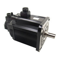
Servomotors
Brand:
YASKAWA
| Category:
Engine
| Size: 7.73 MB
Table of Contents
Safety Information
6
Notes for Safe Operation
7
Table of Contents
13
Outline
25
Checking Products
26
Check Items
26
Servomotors
26
1 Outline
26
Servopacks
27
Product Part Names
28
Servomotors
28
SGMAH and SGMPH Without Gears and Brakes
28
SGMGH/SGMSH/SGMDH/SGMUH Without Gears and Brakes
28
Servopacks
29
SGDH for 30 W to 5.0 Kw
29
SGDH for 6.0 Kw to 15.0 Kw
30
Examples of Servo System Configurations
31
Single-Phase, 100 V, 200 V and 220 V Main Circuit
31
Three-Phase, 200 V Main Circuit
32
Three-Phase, 400 V Main Circuit
33
Applicable Standards
34
North American Safety Standards (UL, CSA)
34
CE Marking
34
2 Selections
35
Servomotor Model Designations
36
Model SGMAH (3000 Min -1 )
36
Without Gears
36
With Gears
37
Model SGMPH (3000 Min -1 )
38
Model SGMGH (1500 Min -1 )
40
Model SGMGH (1000 Min -1 )
42
Model SGMSH (3000 Min -1 )
44
Model SGMDH (2000 Min -1 )
46
Model SGMUH (6000 Min -1)
47
Selecting Servomotors
48
Support Tool for the Capacity Selection of the AC Servomotors
48
Servomotor Capacity Selection Examples
48
SERVOPACK Model Designations
49
Σ-II Series Servopacks and Applicable Servomotors
50
Selecting Cables
51
Cables for SGMAH and SGMPH Servomotors
51
Cables for SGMGH/SGMSH/SGMDH/SGMUH Servomotors
56
Selecting Peripheral Devices
60
Special Options
60
Molded-Case Circuit Breaker and Fuse Capacity
63
Noise Filters, Magnetic Contactors, Surge Suppressors and DC Reactors
64
Regenerative Resistors and Brake Power Supply Units
65
Specifications and Dimensional Drawings
67
3 Specifications and Dimensional Drawings
68
Ratings and Specifications of SGMAH (3000 Min -1)
70
SGMAH Servomotors Without Gears
70
SGMAH Servomotors with Standard Backlash Gears
72
SGMAH Servomotors with Low-Backlash Gears
74
Ratings and Specifications of SGMPH (3000 Min -1)
77
SGMPH Servomotors Without Gears
77
SGMPH Servomotors with Standard Backlash Gears
79
SGMPH Servomotors with Low-Backlash Gears
81
Ratings and Specifications of SGMGH (1500 Min -1)
83
SGMGH Servomotors (1500Min -1) Without Gears
83
3.3.1 SGMGH Servomotors (1500Min
84
3.3 Ratings and Specifications of SGMGH (1500Min
85
3.3.1 SGMGH Servomotors (1500Min
86
3.3 Ratings and Specifications of SGMGH (1500Min
87
3.3.2 SGMGH Servomotors (1500Min
87
SGMGH Servomotors (1500Min -1) with Standard Backlash Gears
87
3.3.2 SGMGH Servomotors (1500Min
88
3.3 Ratings and Specifications of SGMGH (1500Min
89
SGMGH Servomotors
89
SGMGH Servomotors (1500Min -1) with Low-Backlash Gears
90
3.3 Ratings and Specifications of SGMGH (1500Min
91
3.4.1 SGMGH Servomotors (1000Min
92
Ratings and Specifications of SGMGH (1000Min -1)
92
SGMGH Servomotors (1000Min -1) Without Gears
92
3.4 Ratings and Specifications of SGMGH (1000Min
93
3.4 Ratings and Specifications of SGMGH (1000Min
95
SGMGH Servomotors (1000Min -1) with Standard Backlash Gears
95
3.4.2 SGMGH Servomotors (1000Min
96
3.4.3 SGMGH Servomotors (1000 Min
97
SGMGH Servomotors (1000 Min -1) with Low-Backlash Gears
97
Ratings and Specifications of SGMSH (3000Min -1)
99
SGMSH Servomotors (3000Min -1) Without Gears
99
3.5 Ratings and Specifications of SGMSH (3000Min
101
3.5 Ratings and Specifications of SGMSH (3000Min
103
Ratings and Specifications of SGMDH (2000Min -1)
105
SGMDH Servomotors (2000Min -1) with Holding Brakes
105
Ratings and Specifications of SGMUH (6000Min -1)
107
SGMUH Servomotors (6000Min -1) Without Holding Brakes
107
Mechanical Specifications of Servomotors
109
Precautions on Servomotor Installation
109
Mechanical Tolerance
110
Direction of Servomotor Rotation
111
Impact Resistance
111
Vibration Resistance
111
Vibration Class
111
Terms and Data for Servomotors with Gears
112
Servomotor Dimensional Drawings
114
With Standard Backlash Gears
114
With Low-Backlash Gears
114
Dimensional Drawings of SGMAH Servomotors (3000 Min -1)
115
SGMAH Servomotors (3000 Min -1) Without Gears
115
Without Gears
114
Without Gears
116
Dimensional Drawings of SGMAH Servomotors
117
Model SGMAH (3000 Min -1 )
117
SGMAH Servomotors (3000 Min -1) with Brakes
119
SGMAH Servomotors (3000 Min -1) with Standard Backlash Gears
123
SGMAH Servomotors (3000 Min -1) with Standard Backlash Gears and Brakes
130
SGMAH Servomotors (3000 Min -1) with Low-Backlash Gears
137
Dimensional Drawings of SGMPH Servomotors (3000 Min -1)
145
SGMPH Servomotors (3000 Min -1) Without Gears and Brake
145
Model SGMPH (3000 Min )
146
SGMPH Servomotors (3000 Min -1) with Brakes
147
SGMPH Servomotors (3000 Min -1) with Standard Backlash Gears
149
SGMPH Servomotors (3000 Min -1) with Standard Backlash Gears and Brakes
152
SGMPH Servomotors (3000 Min -1) with Low-Backlash Gears
155
Dimensional Drawing of Output Shafts with Oil Seals for SGMAH and SGMPH Servomotors
159
SGMAH Servomotors
159
SGMPH Servomotors
159
Dimensional Drawings of SGMGH Servomotors (1500 Min -1)
160
SGMGH Servomotors (1500 Min -1) Without Gears and Brakes
160
Model SGMGH (1500 Min )
164
Model SGMGH (1000 Min -1 )
165
SGMGH Servomotors (1500Min -1) with Standard Backlash Gears and With-Out Brakes (Foot-Mounted Type)
168
SGMGH Servomotors (1500Min -1) with Low-Backlash Gears and Withoutbrakes (Flange-Mounted Type)
182
Dimensional Drawings of SGMGH Servomotors (1000 Min -1)
186
SGMGH Servomotors (1000 Min -1) Without Gears and Brakes
186
SGMGH Servomotors (1000 Min -1) Without Gears and with Brakes
188
SGMGH Servomotors (1000 Min -1) with Standard Backlash Gears and With-Out Brakes (Foot-Mounted Type)
191
SGMGH Servomotors (1000 Min -1) with Low-Backlash Gears and Withoutbrakes (Flange-Mounted Type)
203
Dimensional Drawings of SGMSH Servomotors (3000Min -1)
207
SGMSH Servomotors (3000Min -1) Without Gears and Without Brakes
207
SGMSH Servomotors (3000 Min -1) 200-V Specifications Without Gears Withbrakes
209
SGMSH Servomotors (3000 Min -1) 400-V Specifications Without Gears Withbrakes
211
SGMSH Servomotors (3000 Min -1) with Low-Backlash Gears and Withoutbrakes (Flange-Mounted Type)
213
Model SGMSH (3000 Min -1 )
216
SGMSH Servomotors (3000 Min Without Brakes (Flange-Mounted Type)
216
SGMDH Servomotors (2000Min -1) Without Gears and With/Without Brakes
217
Servomotors SGMGH (1500 Min -1) 400-V Specifications Without Gears and with Brakes
165
Dimensional Drawings of SGMDH Servomotors (2000Min -1 )
217
With/Without Brakes
217
SGMUH Servomotors (6000Min -1) Without Gears and Without Brakes
219
Dimensional Drawings of SGMUH Servomotors (6000Min -1 )
219
Without Gears and Without Brakes
219
SGMUH Servomotors (6000Min -1) Without Gears and with Brakes
220
Shaft End Specifications for SGMGH, SGMSH and SGMDH Servomotors
222
4 SERVOPACK Specifications and Dimensional Drawings
225
SERVOPACK Ratings and Specifications
225
Single-Phase 100 V
225
Three-Phase 400 V
225
SERVOPACK Ratings and Specifications
227
Single-Phase 100 V
227
Single-Phase/Three-Phase 200 V
227
Single-Phase 220 V (Option)
228
Three-Phase 400 V
228
SERVOPACK Ratings and Specifications
229
SERVOPACK Installation
231
SERVOPACK Internal Block Diagrams
233
Single-Phase 200 V, 30 W to 400 W, and 100 V, 30 W to 200 W Models
233
Three-Phase 200 V, 500 W to 1.5 Kw, and Single-Phase 220 V, 800 W, 1.5 Kw Models
234
Three-Phase 200 V, 2.0 Kw to 5.0 Kw Models
235
Three-Phase 200 V, 6.0 Kw to 15 Kw Models
236
Three-Phase 400 V, 500 W to 3.0 Kw Models
237
Three-Phase 400 V, 5.0 Kw Model
238
Three-Phase 400 V, 6.0 Kw, 7.5 Kw Models
239
Three-Phase 400 V, 11.0 Kw, 15.0 Kw Models
240
Servopack’s Power Supply Capacities and Power Losses
241
SERVOPACK Overload Characteristics and Allowable Load Moment of Inertia
243
Overload Characteristics
243
Starting and Stopping Time
244
Load Moment of Inertia
244
SERVOPACK Dimensional Drawings
247
Model
247
Dimensional Drawings of Base-Mounted SERVOPACK Model
248
Single-Phase 100 V: 30 W/50 W/100 W (A3BE/A5BE/01BE)
248
Single-Phase 200 V: 30 W/50 W/100 W/200 W (A3AE/A5AE/01AE/02AE)
248
Single-Phase 100 V: 200 W (02BE) Single-Phase 200 V: 400 W (04AE)
249
Three-Phase 200 V: 500 W/750 W/1.0 Kw (05AE/08AE/10AE)
250
Single-Phase 220 V: 750 W (08AE-S)
250
Three-Phase 200 V: 1.5 Kw (15AE)
251
Three-Phase 400 V: 500 W/750 W/1.0 Kw/1.5 Kw (05DE/08DE/10DE/15DE)
251
Single-Phase 220 V: 1.5 Kw (15AE-S) Three-Phase 200 V: 2.0 Kw/3.0 Kw (20AE/30AE) Three-Phase 400 V: 2.0 Kw/3.0 Kw (20DE/30DE)
252
Three-Phase 200 V: 5.0 Kw (50AE) Three-Phase 400 V: 5.0 Kw (50DE)
253
Three-Phase 200 V: 6.0 Kw/7.5 Kw (60AE/75AE)
254
Three-Phase 400 V: 6.0 Kw/7.5 Kw (60DE/75DE)
255
Three-Phase 200 V: 11.0 Kw/15.0 Kw (1AAE/1EAE)
256
Three-Phase 400 V: 11.0 Kw/15.0 Kw (1ADE/1EDE)
257
Dimensional Drawings of Rack-Mounted SERVOPACK Model
258
Single-Phase 100 V: 30 W/50 W/100 W (A3BE-R/A5BE-R/01BE-R)
258
Single-Phase 200 V: 30 W/50 W/100 W/200 W (A3AE-R/A5AE-R/01AE-R/02AE-R)
258
Single-Phase 100 V: 200 W (02BE-R) Single-Phase 200 V: 400 W (04AE-R)
259
Single-Phase 220 V: 750 W (08AE-S-R)
260
Three-Phase 200 V: 500 W/750 W/1.0 Kw (05AE-R/08AE-R/10AE-R)
260
Three-Phase 200 V: 1.5 Kw (15AE-R)
261
Three-Phase 400 V: 500 W/750 W/1.0 Kw/1.5 Kw (05DE-R/08DE-R/10DE-R/15DE-R)
261
Single-Phase 220 V: 1.5 Kw (15AE-S-R)
262
Three-Phase 200 V: 2.0 Kw/3.0 Kw (20AE-R/30AE-R)
263
Three-Phase 400 V: 2.0 Kw/3.0 Kw (20DE-R/30DE-R)
263
Three-Phase 200 V: 5.0 Kw (50AE-R) Three-Phase 400 V: 5.0 Kw (50DE-R)
264
Dimensional Drawings of Duct-Ventilated SERVOPACK Model
265
Three-Phase 200 V: 6.0 Kw/7.5 Kw (60AE-P/75AE-P)
265
Three-Phase 400 V: 6.0 Kw/7.5 Kw (60DE-P/75DE-P)
266
Three-Phase 200 V: 11.0 Kw/15.0 Kw (1AAE-P/1EAE-P)
267
Three-Phase 400 V: 11.0 Kw/15.0 Kw (1ADE-P/1EDE-P)
268
5 Specifications and Dimensional Drawings of Cables and Peripheral Devices
269
Main Circuit Cable
269
Specifications and Dimensional Drawings of Servomotor Main Circuit Cable
271
Cables for SGMAH and SGMPH Servomotors Without Brakes
271
Cables for SGMAH and SGMPH Servomotors with Brakes
271
Flexible Cables for SGMAH and SGMPH Servomotors Without Brakes
272
Flexible Cables for SGMAH and SGMPH Servomotors with Brakes
273
Cables for 400 V SGMAH and SGMPH Servomotors Without Brakes
273
Cables for 400 V SGMAH and SGMPH Servomotors with Brakes
274
Servomotor Main Circuit Wire Size and Connectors
275
Wire Size
275
SGMAH and SGMPH Servomotor Connectors for Standard Environments
276
SGMGH, SGMSH, SGMDH, and SGMUH Servomotor Connector Configurations
279
SGMGH Servomotor (1500 Min -1) Connectors for Standard Environments
280
SGMGH Servomotor
282
SGMGH Servomotor (1000 Min -1) Connectors for Standard Environments
283
SGMSH Servomotor (3000 Min -1) Connectors for Standard Environments
285
SGMDH Servomotor (2000 Min -1) Connectors for Standard Environments
287
SGMUH Servomotor (6000 Min -1) Connectors for Standard Environments
287
Without Brakes
287
SGMGH Servomotor (1500 Min -1) Connectors Conforming to IP67 and Euro-Pean Safety Standards
290
SGMGH Servomotor (1000 Min -1) Connectors Conforming to IP67 and Euro-Pean Safety Standards
295
SGMSH Servomotors (3000 Min -1) Connectors Conforming to IP67 and Euro-Pean Safety Standards
298
SGMSH Servomotors (3000 Min -1 Without Brakes (Flange-Mounted Type)
298
SGMDH Servomotors (2000 Min -1) Connectors Conforming to IP67 and Euro-Pean Safety Standards
302
Without Brakes
302
With Brakes
302
SGMUH Servomotors (6000 Min -1) Connectors Conforming to IP67 and Euro-Pean Safety Standards
303
Connector Dimensional Drawings
306
SERVOPACK Main Circuit Wire Size
313
Cable Types
313
Encoder Cable for SGMGH, SGMSH, SGMDH, and SGMUH Servomotors
316
Encoder Cable with Connectors for SGMAH and SGMPH Servomotors
316
Encoder Cables for CN2 Connector
316
Encoder Cable with a SERVOPACK Connector and Encoder Loose Leads for SGMAH and SGMPH Servomotors
317
Encoder Cable with a SERVOPACK Connector and Encoder Loose Leads for SGMGH, SGMSH, SGMDH, and SGMUH Servomotors
318
Encoder Flexible Cables for SGMAH and SGMPH Servomotors
320
Encoder Flexible Cables for SGMGH, SGMSH, SGMDH, and SGMUH Servomotors
321
Connectors and Cables for Encoder Signals
323
Connectors and Cables for SGMAH and SGMPH Servomotors
323
Connectors and Cables for SGMGH, SGMSH, SGMDH, and SGMUH Servomotors
325
Flexible Cables
327
I/O Signal Cables for CN1 Connector
328
Standard Cables
328
Connector Type and Cable Size
328
Connection Diagram
330
Peripheral Devices
331
Cables for Connecting Personal Computers
331
Digital Operator
332
Cables for Analog Monitor
333
Connector Terminal Block Converter Unit
334
Brake Power Supply Unit
335
External Regenerative Resistor
337
Regenerative Resistor Unit
339
Absolute Encoder Battery
340
Molded-Case Circuit Breaker (MCCB)
341
Noise Filter
343
Magnetic Contactor
348
Surge Suppressor
352
DC Reactor for Harmonic Suppression
354
Variable Resistor for Speed and Torque Setting
356
Encoder Signal Converter Unit
357
MECHATROLINK-I I/F Unit
358
Devicenet I/F Unit
359
PROFIBUS-DP I/F Unit
360
INDEXER Module
362
Setup Support Tool Sigmaindexer
363
Fully-Closed I/F Unit
364
6 Wiring
365
Wiring Main Circuit
366
Names and Functions of Main Circuit Terminals
366
Wiring Main Circuit Power Supply Connector (Spring Type)
368
Typical Main Circuit Wiring Examples
369
Wiring Encoders
372
Connecting an Encoder (CN2) and Output Signals from the SERVOPACK (CN1)
372
Encoder Connector (CN2) Terminal Layout
373
Examples of I/O Signal Connections
374
Speed Control Mode
374
Position Control Mode
375
Torque Control Mode
376
I/O Signal Connector (CN1) Terminal Layout
377
I/O Signal (CN1) Names and Functions
378
Interface Circuit
380
Others
383
Wiring Precautions
383
Wiring for Noise Control
384
Installation Conditions of EMC Directives
387
Installation Conditions of UL Standards
390
Using more than One SERVOPACK
391
Extending Encoder Cables
392
Operating Conditions on 400-V Power Supply Voltage
394
DC Reactor for Harmonic Suppression
395
Regenerative Power and Regenerative Resistance
397
Connecting External Regenerative Resistors
397
7 Digital Operator/Panel Operator
402
Functions on Digital Operator/Panel Operator
403
Connecting the Digital Operator
403
Key Names and Functions
404
Basic Mode Selection and Operation
405
Status Display
407
Operation in Utility Function Mode (Fn )
409
List of Utility Function Modes
409
Alarm Traceback Data Display (Fn000)
410
Zero-Point Search Mode (Fn003)
411
Parameter Settings Initialization (Fn005)
412
Alarm Traceback Data Clear (Fn006)
413
Automatic Offset-Adjustment of Motor Current Detection Signal
414
Manual Offset-Adjustment of Motor Current Detection Signal (Fn00F)
415
Password Setting (Protects Parameters from Being Changed) (Fn010)
416
Motor Models Display (Fn011)
417
Software Version Display (Fn012)
418
Application Module Detection Results Clear (Fn014)
419
Operation in Parameter Setting Mode (Pn )
420
Setting Parameters
420
Input Circuit Signal Allocation
424
Output Circuit Signal Allocation
427
Operation in Monitor Mode (un )
429
List of Monitor Modes
429
8 Operation
433
Trial Operation
436
Trial Operation for Servomotor Without Load
438
Trial Operation for Servomotor Without Load from Host Reference
441
Trial Operation with the Servomotor Connected to the Machine
447
Servomotor with Brakes
448
Position Control by Host Controller
448
Control Mode Selection
449
Setting Common Basic Functions
450
Setting the Servo on Signal
450
Switching the Servomotor Rotation Direction
451
Setting the Overtravel Limit Function
452
Setting for Holding Brakes
454
Selecting the Stopping Method after Servo off
457
Instantaneous Power Loss Settings
458
Absolute Encoders
459
Interface Circuits
460
Selecting an Absolute Encoder
461
Handling Batteries
461
Replacing Batteries
462
Absolute Encoder Setup (Fn008)
462
Absolute Encoder Reception Sequence
464
Multiturn Limit Setting
468
Multiturn Limit Setting When Multiturn Limit Disagreement (A.CC) Occurred
469
Operating Using Speed Control with Analog Reference
470
Setting Parameters
470
Setting Input Signals
471
Adjusting Offset
472
Soft Start
475
Speed Reference Filter
475
Using the Zero Clamp Function
475
Encoder Signal Output
477
Speed Coincidence Output
479
Operating Using Position Control
480
Setting Parameters
480
Setting the Electronic Gear
482
Position Reference
485
Smoothing
489
Positioning Completed Output Signal
490
Positioning Near Signal
491
Reference Pulse Inhibit Function (INHIBIT)
492
Operating Using Torque Control
493
Torque Reference Input
493
Setting Parameters
493
Adjusting the Reference Offset
494
Limiting Servomotor Speed During Torque Control
496
Operating Using Speed Control with an Internally Set Speed
498
Setting Parameters
498
Input Signal Settings
499
Operating Using an Internally Set Speed
499
Limiting Torque
501
Internal Torque Limit (Limiting Maximum Output Torque)
501
External Torque Limit (Output Torque Limiting by Input Signals)
502
Torque Limiting Using an Analog Voltage Reference
504
Torque Limiting Using an External Torque Limit and Analog Voltage Reference
505
Checking Output Torque Limiting During Operation
506
Switching the Control Mode
507
Control Mode Selection
507
Setting Parameters
507
Other Output Signals
509
Servo Alarm Output (ALM) and Alarm Code Output (ALO1, ALO2, ALO3)
509
Warning Output (/WARN)
510
Running Output Signal (/TGON)
510
Servo Ready (/S-RDY) Output
511
9 Adjustments
512
Autotuning
513
Servo Gain Adjustment Methods
513
List of Servo Adjustment Functions
514
Online Autotuning
516
Online Autotuning Procedure
517
Selecting the Online Autotuning Execution Method
518
Machine Rigidity Setting for Online Autotuning
519
Method for Changing the Machine Rigidity Setting
520
Saving the Results of Online Autotuning
521
Procedure for Saving the Results of Online Autotuning
522
Manual Tuning
523
Explanation of Servo Gain
523
Servo Gain Manual Tuning
524
Position Loop Gain
524
Speed Loop Gain
525
Speed Loop Integral Time Constant
525
Servo Gain Adjustment Functions
526
Feed-Forward Reference
526
Torque Feed-Forward
527
Speed Feed-Forward
528
Proportional Control Operation (Proportional Operation Reference)
529
Using the Mode Switch (P/PI Switching)
530
Setting the Speed Bias
533
Speed Feedback Filter
533
Speed Feedback Compensation
534
Switching Gain Settings
536
Torque Reference Filter
537
Analog Monitor
539
10 Inspection, Maintenance, and Troubleshooting
541
Alarm Display Table
542
Troubleshooting
542
Warning Display
544
Alarm Display Table When the Application Module Is Used
545
Warning Display Table When the Application Module Is Used
546
Alarm Display Table When the Linear Motor Is Used
546
Troubleshooting of Alarm and Warning
547
Warning Display and Troubleshooting
556
Troubleshooting for Malfunction Without Alarm Display
557
Inspection and Maintenance
562
Servomotor Inspection
562
SERVOPACK Inspection
562
Servopack's Parts Replacement Schedule
563
11 Appendix
564
Selection Example for Speed Control
565
Servomotor Capacity Selection Examples
565
Selection Example for Position Control
567
Calculating the Required Capacity of Regenerative Resistors
570
Connection to Host Controller
579
Example of Connection to MP920 4-Axes Analog Module SVA-01
579
Example of Connection to CP-9200SH Servo Controller Module SVA (SERVOPACK in Speed Control Mode)
580
Example of Connection to MEMOCON GL120/130 Series Motion Module MC20
581
Example of Connection to MEMOCON GL60/70 Series Positioning Module B2813 (SERVOPACK in Position Control Mode)
582
Example of Connection to Omron's Motion Control Unit
583
Example of Connection to Omron's Position Control Unit
584
Example of Connection to Omron's Position Control Unit C500-NC221 (SERVOPACK in Speed Control Mode)
585
Example of Connection to Omron's Position Control Unit
585
Example of Connection to Omron’s Position Control Unit C500-NC112 (SERVOPACK in Position Control Mode)
586
Example of Connection to Mitsubishi's AD72 Positioning Unit (SERVOPACK in Speed Control Mode)
587
Example of Connection to Mitsubishi's AD75 Positioning Unit (SERVOPACK in Position Control Mode)
588
List of Parameters
589
Utility Functions List
589
List of Parameters
590
Monitor Modes
606
Parameter Recording Table
607
Index
610
Revision History
615
Advertisement
YASKAWA SGDH User Manual (341 pages)
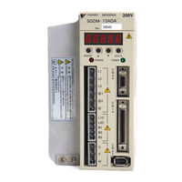
AC Servo Drives
Brand:
YASKAWA
| Category:
Servo Drives
| Size: 18.19 MB
Table of Contents
Table of Contents
14
1 Outline
21
Checking Products
22
Check Items
22
Servomotors
22
Servopacks
22
Examples of Servo System Configurations
23
Three-Phase, 200 V Series
23
Three-Phase, 400 V Series
24
Applicable Standards
25
North American Safety Standards (UL)
25
CE Marking
25
2 Selections
26
Servomotor Model Designations
27
SERVOPACK Model Designations
28
Σ-II Series Servopacks and Applicable Servomotor
29
Selecting Cables
30
Cables for SGMVH Servomotor
30
Selecting Peripheral Devices
31
Special Options
31
Molded-Case Circuit Breaker and Fuse Capacity
33
Noise Filters, Magnetic Contactors, and Brake Power Supply Units
34
Regenerative Resistor Units
34
Dynamic Brake (DB) Units
35
Thermal Relays
36
3 Servomotor Specifications and Dimensional Drawings
37
Ratings and Specifications of SGMVH (1500 Min -1 )
38
Ratings and Specifications of SGMVH (800 Min -1 )
43
Mechanical Specifications of Servomotors
45
Precautions on Servomotor Installation
45
Allowable Radial and Thrust Loads
49
Mechanical Tolerance
50
Direction of Servomotor Rotation
50
Impact Resistance
50
Vibration Resistance
50
Vibration Class
51
Dimensional Drawings of SGMVH Servomotors (1500 Min -1 )
58
Dimensional Drawings of SGMVH Servomotors (800 Min -1 )
61
4 SERVOPACK Specifications and Dimensional Drawings
62
SERVOPACK Ratings and Specifications
63
SERVOPACK Ratings and Specifications
64
SERVOPACK Installation
66
SERVOPACK Internal Block Diagrams
68
Three-Phase 200 V, 22 Kw, 30 Kw Models
68
Three-Phase 200 V, 37 Kw Model
69
Three-Phase 400 V, 22 Kw, 30 Kw Models
70
Three-Phase 400 V, 37 Kw Model
70
Three-Phase 400 V, 45 Kw, 55 Kw Models
71
Three-Phase 400 V, 90 Kw Model
71
Servopack's Power Supply Capacities and Power Losses
72
SERVOPACK Overload Characteristics and Allowable Load Moment of Inertia
73
Overload Characteristics
73
Starting and Stopping Time
74
Load Moment of Inertia
75
SERVOPACK Dimensional Drawings
77
Three-Phase 200 V, 22 Kw, 30 Kw Models
77
Three-Phase 200 V, 37 Kw Model
78
Three-Phase 400 V, 22 Kw Model
79
Three-Phase 400 V, 30 Kw Model
80
Three-Phase 400 V, 37 Kw Model
81
Three-Phase 400 V, 45 Kw, 55 Kw Models
81
Three-Phase 400 V, 90 Kw Model
82
5 Specifications and Dimensional Drawings of Cables and Peripheral Devices
83
SERVOPACK Main Circuit Wire Size
84
Wiring Cables to Main Circuit Terminals
84
Three-Phase 200
85
Three-Phase 400
86
Encoder Cables for CN2 Connector
88
Encoder Cable with Connectors on both Ends
88
Cable with Loose Wire at Encoder End
89
Connectors and Cables for Encoder Signals
90
I/O Signal Cables for CN1 Connector
92
Connector Type and Cable Size
92
Connection Diagram
94
Peripheral Devices
95
Cables for Connecting Personal Computers
95
Digital Operator
96
Cables for Analog Monitor
97
Connector Terminal Block Converter Unit
98
Brake Power Supply Unit
99
Absolute Encoder Battery
100
Molded-Case Circuit Breaker (MCCB)
101
Noise Filter
102
Surge Absorber
104
Regenerative Resistor Unit
105
Dynamic Brake (DB) Unit
111
Thermal Relays
118
Variable Resistor for Speed and Torque Setting
121
Encoder Signal Converter Unit
122
MECHATROLINK Application Module
123
Devicenet Application Module
124
PROFIBUS-DP Application Module
125
Fully-Closed Application Module
126
6 Wiring
127
Wiring Main Circuit
128
Names and Functions of Main Circuit Terminals
128
Typical Main Circuit Wiring Examples
130
Wiring Encoders
134
Connecting an Encoder (CN2) and Output Signals from the SERVOPACK (CN1)
134
Encoder Connector (CN2) Terminal Layout
135
I/O Signal Connections
136
Example of I/O Signal Connection
136
I/O Signal Connector (CN1) Terminal Layout
137
I/O Signal (CN1) Names and Functions
138
Interface Circuit
140
Others
143
Wiring Precautions
143
Wiring for Noise Control
144
Using more than One SERVOPACK
148
7 Digital Operator/Panel Operator
152
Functions on Digital Operator/Panel Operator
152
Connecting the Digital Operator
152
Key Names and Functions
153
Basic Mode Selection and Operation
154
Status Display
155
Operation in Utility Function Mode (Fn )
157
List of Utility Function Modes
157
Alarm Traceback Data Display (Fn000)
158
Zero-Point Search Mode (Fn003)
159
Parameter Settings Initialization (Fn005)
160
Alarm Traceback Data Clear (Fn006)
161
Manual Zero Adjustment and Gain Adjustment of Analog Monitor Output (Fn00C, Fn00D)
162
Offset Adjustment of Motor Current Detection Signal (Fn00E, Fn00F)
165
Password Setting (Protects Parameters from Being Changed) (Fn010)
167
Motor Models Display (Fn011)
168
Software Version Display (Fn012)
169
Application Module Detection Results Clear (Fn014)
170
Operation in Parameter Setting Mode (Pn )
171
Setting Parameters
171
Input Circuit Signal Allocation
174
Output Circuit Signal Allocation
177
Operation in Monitor Mode (un )
179
List of Monitor Modes
179
8 Operation
183
Trial Operation
186
Trial Operation for Servomotor Without Load
188
Trial Operation for Servomotor Without Load from Host Reference
197
Trial Operation with the Servomotor Connected to the Machine
197
Servomotor with Brakes
198
Position Control by Host Controller
198
Control Mode Selection
199
Setting Common Basic Functions
200
Setting the Servo on Signal
200
Switching the Servomotor Rotation Direction
201
Setting the Overtravel Limit Function
202
Setting for Holding Brakes
204
Selecting the Stopping Method after Servo off
208
Instantaneous Power Loss Settings
209
Absolute Encoders
210
Interface Circuits
211
Selecting an Absolute Encoder
212
Handling Batteries
212
Replacing Batteries
213
Absolute Encoder Setup (Fn008)
214
Absolute Encoder Reception Sequence
215
Multiturn Limit Setting
218
Multiturn Limit Setting When Multiturn Limit Disagreement (A.CC) Occurred
219
Operating Using Speed Control with Analog Reference
220
Setting Parameters
220
Setting Input Signals
221
Adjusting Offset
222
Soft Start
225
Speed Reference Filter
225
Using the Zero Clamp Function
225
Encoder Signal Output
227
Speed Coincidence Output
230
Operating Using Position Control
231
Setting Parameters
231
Setting the Electronic Gear
233
Operating Using Position Control
233
Position Reference
236
Smoothing
239
Positioning Completed Output Signal
240
Positioning Near Signal
241
Reference Pulse Inhibit Function (INHIBIT)
242
Reference Pulse Input Multiplication Switching Function
243
Operating Using Torque Control
245
Setting Parameters
245
Torque Reference Input
245
Adjusting the Reference Offset
246
Limiting Servomotor Speed During Torque Control
248
Operating Using Speed Control with an Internally Set Speed
250
Setting Parameters
250
Input Signal Settings
251
Operating Using an Internally Set Speed
251
Limiting Torque
253
Internal Torque Limit (Limiting Maximum Output Torque)
253
External Torque Limit (Output Torque Limiting by Input Signals)
254
Torque Limiting Using an Analog Voltage Reference
255
Torque Limiting Using an External Torque Limit and Analog Voltage Reference
256
Checking Output Torque Limiting During Operation
257
Control Mode Selection
258
Setting Parameters
258
Switching the Control Mode
258
Servo Alarm Output (ALM) and Alarm Code Output (ALO1, ALO2, ALO3)
259
Warning Output (/WARN)
260
Servomotor Running Output Signal (/TGON)
260
Servo Ready (/S-RDY) Output
261
9 Adjustments
263
Autotuning
263
Servo Gain Adjustment Methods
263
List of Servo Adjustment Functions
263
Online Autotuning
265
Manual Tuning
265
Explanation of Servo Gain
265
Servo Gain Manual Tuning
266
Position Loop Gain
266
Speed Loop Gain
267
Speed Loop Integral Time Constant
267
Servo Gain Adjustment Functions
268
Feed-Forward Reference
268
Torque Feed-Forward
268
Speed Feed-Forward
269
Proportional Control Operation (Proportional Operation Reference)
270
Using the Mode Switch (P/PI Switching)
271
Setting the Speed Bias
274
Speed Feedback Filter
274
Speed Feedback Compensation
274
Switching Gain Settings
275
Torque Reference Filter
277
Analog Monitor
281
10 Inspection, Maintenance, and Troubleshooting
283
Alarm Display Table
284
Troubleshooting
284
Warning Display
286
Alarm Display Table When the Application Module Is Used
287
Warning Display Table When the Application Module Is Used
288
Troubleshooting of Alarm and Warning
289
Troubleshooting for Malfunction Without Alarm Display
298
Inspection and Maintenance
302
Servomotor Inspection
302
SERVOPACK Inspection
302
Servopack's Parts Replacement Schedule
303
11 Appendix
304
Selection Example for Speed Control
305
Selection Example for Position Control
307
Connection to Host Controller
310
Example of Connection to MP2200/MP2300 Motion Module SVA-01
310
Example of Connection to MP920 4-Axes Analog Module SVA-01
311
Example of Connection to Omron's Motion Control Unit
312
Example of Connection to Omron's Position Control Unit
313
Example of Connection to Mitsubishi's AD72 Positioning Unit
314
Unit (SERVOPACK in Speed Control Mode)
314
Example of Connection to Mitsubishi's AD75 Positioning Unit (SERVOPACK in Position Control Mode)
315
List of Parameters
316
Utility Functions List
316
List of Parameters
317
Parameter Recording Table
332
Index
335
Revision History
339
YASKAWA SGDH User Manual (408 pages)
Brand:
YASKAWA
| Category:
Engine
| Size: 6.88 MB
Table of Contents
Table of Contents
377
Connecting the GL-Series MC20 Motion Module
378
Connecting the CP-9200SH Servo Controller Module (SVA)
379
Connecting the GL-Series B2813 Positioning Module
380
Connecting Omron's C500-NC221 Position Control Unit
381
Connecting Omron's C500-NC112 Position Control Unit
382
Connecting Mitsubishi's AD72 Positioning Unit
383
Connecting Mitsubishi's AD75 Positioning Unit
384
Advertisement
Advertisement
Related Products
YASKAWA SGMDH
YASKAWA SGMAS
YASKAWA SGMPS
YASKAWA SGMSS
YASKAWA SGMCS
YASKAWA S-II Series
YASKAWA SGDH SERVOPACK
YASKAWA SGDH Sigma II
YASKAWA SGDH-2BAEB
YASKAWA SGDH-3ZAEB
YASKAWA Categories
Controller
DC Drives
Servo Drives
Robotics
Control Unit
More YASKAWA Manuals
Login
Sign In
OR
Sign in with Facebook
Sign in with Google
Upload manual
Upload from disk
Upload from URL