Table of Contents
Advertisement
Quick Links
Agilent 4287A RF LCR Meter
Operation Manual
Twelfth Edition
FIRMWARE REVISIONS/SERIAL NUMBERS
This manual applies directly to instruments that have the firmware revision 2.0x and serial number prefix MY433.
For additional important information about firmware revisions and serial numbers, see Appendix A.
Agilent Part No. 04287-90024
August 2012
Advertisement
Table of Contents

Related Manuals for Agilent Technologies Twelfth 4287A RF LCR


Summary of Contents for Agilent Technologies Twelfth 4287A RF LCR
- Page 1 Agilent 4287A RF LCR Meter Operation Manual Twelfth Edition FIRMWARE REVISIONS/SERIAL NUMBERS This manual applies directly to instruments that have the firmware revision 2.0x and serial number prefix MY433. For additional important information about firmware revisions and serial numbers, see Appendix A. Agilent Part No.
- Page 2 X/Open Company Limited. Portions ©Copyright 1996, Microsoft Corporation. All rights reserved. © Copyright 2000, 2001, 2002, 2003, 2004, 2005, 2012 Agilent Technologies Manual Printing History The manual’s printing date and part number indicate its current edition. The printing date changes when a new edition is printed.
- Page 3 To avoid the danger of introducing additional hazards, do not install substitute parts or perform unauthorized modifications to the instrument. Return the instrument to an Agilent Technologies Sales and Service Office for service and repair to ensure that safety features are maintained in operational condition.
- Page 4 Certification Agilent Technologies certifies that this product met its published specifications at the time of shipment from the factory. Agilent Technologies further certifies that its calibration measurements are traceable to the United States National Institute of Standards and Technology, to the extent allowed by the Institution’s calibration facility or by the...
- Page 5 For warranty service or repair, this product must be returned to a service facility designated by Agilent Technologies. Buyer shall prepay shipping charges to Agilent Technologies, and Agilent Technologies shall pay shipping charges to return the product to Buyer. However, Buyer shall pay all shipping charges, duties, and taxes for products returned to Agilent Technologies from another country.
- Page 6 Assistance Product maintenance agreements and other customer assistance agreements are available for Agilent Technologies products. For any assistance, contact your nearest Agilent Technologies Sales and Service Office. Addresses are provided at the back of this manual. Typeface Conventions Bold Boldface type is used when a term is defined. For example: icons are symbols.
- Page 7 Do not allow any computer virus to infect the system. This machine has no virus check function nor anti-virus software installed. Agilent Technologies will not be held liable for any failure or damage arising from negligence regarding these prohibitions and warnings.
-
Page 9: Table Of Contents
Contents 1. How to Use This Operation Manual Relationship of Operation Manual Contents to the Handling of the 4287A ......16 2. - Page 10 Contents Executing open calibration ............61 Executing low-loss capacitor calibration .
- Page 11 Contents How to Set the Measurement Point ............103 How to bring up the measurement point setup display .
- Page 12 Contents Setting Measurement Parameter............179 Setting Limit Mode and Reference Value .
- Page 13 Contents Setting the Built-in Speaker (Beep Sound)..........233 Turning the completion beep ON or OFF .
- Page 14 Contents Change 4 ............... . . 288 Miscellaneous Changes.
- Page 15 How to Use This Operation Manual This chapter explains how to most efficiently use this Operation Manual.
-
Page 16: How To Use This Operation Manual Relationship Of Operation Manual Contents To The Handling Of The 4287A
How to Use This Operation Manual Relationship of Operation Manual Contents to the Handling of the 4287A Relationship of Operation Manual Contents to the Handling of the 4287A The chapters of this Operation Manual cover the usage flow from when the product is delivered until when the user has obtained sufficient understanding of the instrument’s functions to use it efficiently. -
Page 17: Installation Guide
Installation Guide This chapter describes procedures for preparing the Agilent 4287A RF LCR meter for use after it is delivered. It also describes daily maintenance procedures. -
Page 18: Incoming Inspection
Installation Guide Incoming Inspection Incoming Inspection WARNING To avoid hazardous electrical shock, do not turn the power on if there are any signs of shipping damage to any part of the exterior (for example, damage on the top cover, bottom cover, side covers, front panel, rear panel, LCD display, connectors or line switch). - Page 19 4. Failure occurs during verification of equipment operation In the case of 1, contact the forwarding agent of the equipment as well as your nearest Agilent Technologies office or sales representative. For subsequent inspection by the forwarding agent, the equipment, the shipping container, cushioning material, and contents must be kept as they are.
-
Page 20: Environmental Requirements
Installation Guide Environmental Requirements Environmental Requirements Ensure that the following environmental requirements are met before using this equipment. Operation environment Use the equipment in the following environment: Environmental requirements 5 °C to 40 °C Temperature Relative 20 % to 80 %, wet bulb temperature ≤ 29 °C (disk drive operating humidity condition) -
Page 21: Ensure Free Space Is Available Around Unit To Allow Speedy Disconnection Of Power Cable In Case Of Emergency
Installation Guide Environmental Requirements Figure 2-1 Ventilation space at installation site Ensure free space is available around unit to allow speedy disconnection of power cable in case of emergency As described in “Disconnection from Supply Source” on page 39, the disconnecting device of the 4287A is the plug or the connector of the power cable. -
Page 22: How To Install Front Handles/Rack Mounting Flanges
Installation Guide How to Install Front Handles/Rack Mounting Flanges How to Install Front Handles/Rack Mounting Flanges The Agilent 4287A can be made more convenient for use with two key options: handles mounted on each side of the front for easy transport and flanges to attach the instrument to a rack as part of a multi-component measurement system (Table 2-2). - Page 23 Installation Guide How to Install Front Handles/Rack Mounting Flanges Figure 2-2 How to remove trim strips from sides Step 3. Use the included screws to mount the two handles on the sides of the Agilent 4287A front panel frame. Figure 2-3 How to install handles on front panel Step 4.
-
Page 24: How To Install Rackmount Kit (Option 1Cm)
Installation Guide How to Install Front Handles/Rack Mounting Flanges Figure 2-4 How to install modified trim strip WARNING If the installed front handle becomes damaged, replace it with a new one immediately. A damaged handle can break while moving or lifting the instrument and cause personal injury or damage to the instrument. - Page 25 Installation Guide How to Install Front Handles/Rack Mounting Flanges Figure 2-5 How to remove trim strips from sides Step 3. Use the included screws to mount the two rack-mounting flanges (locking side plates) on the sides of the Agilent 4287A front panel frame. Figure 2-6 How to install rack-mounting flanges (locking side plates) on front panel Step 4.
-
Page 26: How To Install Rack-Mount And Handle Kit (Option 1Cp)
Installation Guide How to Install Front Handles/Rack Mounting Flanges Figure 2-7 How to remove bottom feet and tilt stands Step 5. Mount the Agilent 4287A on the rack. How to install rack-mount and handle kit (Option 1CP) Install both the rack-mounting flanges and front handles by following these steps: Step 1. - Page 27 Installation Guide How to Install Front Handles/Rack Mounting Flanges Figure 2-8 How to remove trim strips from sides Step 3. Use the included screws to install the front handles and rack-mounting flanges on the sides of the Agilent 4287A front panel frame. Figure 2-9 How to install front handles and rack-mounting flanges Step 4.
- Page 28 Installation Guide How to Install Front Handles/Rack Mounting Flanges Figure 2-10 How to remove bottom feet and tilt stands Step 5. Mount the Agilent 4287A on the rack. WARNING If the installed front handle becomes damaged, replace it with a new one immediately. A damaged handle can break while moving or lifting the instrument and cause personal injury or damage to the instrument.
-
Page 29: Connecting Mouse And Keyboard
Installation Guide Connecting Mouse and Keyboard Connecting Mouse and Keyboard Connect the mouse and keyboard to the designated ports shown in Figure 2-11. Figure 2-11 Connections of mouse and keyboard Chapter 2... -
Page 30: Lan Connection
Installation Guide LAN Connection LAN Connection Step 1. Make the appropriate settings on the 4287A for connecting to a Local Area Network (LAN) according to “Configuring the Network” on page 228. Step 2. Connect the Agilent 4287A to the LAN according to Figure 2-12. NOTE Before connecting to the LAN, be sure to perform the correct LAN settings on the 4287A. -
Page 31: Connecting The Test Head
Installation Guide Connecting the Test Head Connecting the Test Head Connecting the DUT when using a special test fixture When taking measurements while using special test fixtures with 7-mm terminals like the Agilent 16196A, follow these steps to connect the test head, test fixture stand, and 3.5-mm-to-7-mm adapter. - Page 32 Installation Guide Connecting the Test Head NOTE Be sure to use the provided wrench (for 3.5 mm/SMA connector) when tightening the connector nut of the 3.5-mm connector. Using another wrench could result in damage to the connector, which would cause incorrect measurements in the future. Step 4.
-
Page 33: When Using With The Test Head Fixed On A Handler, Etc
Installation Guide Connecting the Test Head When using with the test head fixed on a handler, etc. The test head can be attached to a handler or other automatic equipment instead of using a special test fixture. In this case, secure the test head to the device using the four screw holes provided in the test head as appropriate. -
Page 34: Caution For Connecting The Sma Connector To The Test Head Connector
Installation Guide Connecting the Test Head Caution for connecting the SMA connector to the test head connector Do not rotate the cable to connect the SMA(male) connector to the test head. Rotating the cable may cause damage to the cable’s center conductor. Be sure to rotate the connector nut to connect the SMA cable. -
Page 35: Preparation For Power Supply
Installation Guide Preparation for Power Supply Preparation for Power Supply Before turning on power to the equipment, be sure to verify the following: Check the power supply Check that the power supplied to the Agilent 4287A meets the following requirements: Requirements Voltage 90 to 132 VAC or 198 to 264 VAC... - Page 36 Installation Guide Preparation for Power Supply Figure 2-17 Power cable options Chapter 2...
-
Page 37: Blown Fuse
Blown fuse If the fuse appears to have blown during operation, this equipment may be subject to failure and must be repaired. Contact the Agilent Technologies sales office or the company from which you purchased the equipment. spec :UL/CSA Type, Slo-Blo, 8 A 250 V WARNING Do NOT replace the fuse yourself: this may be dangerous. -
Page 38: Turning The Power On And Off
Installation Guide Turning the Power ON and OFF Turning the Power ON and OFF Perform the following steps to turn the power ON or OFF. Turning the power ON Step 1. If the standby switch ( ) in the lower-left part of the front panel is in the pressed down ) position, press the switch to the popped up position ( Step 2. -
Page 39: Disconnection From Supply Source
Installation Guide Disconnection from Supply Source Disconnection from Supply Source The disconnecting device (device cutting off the power supply) of the 4287A is the plug of the power cable (on AC outlet side or 4287A side). When it is necessary to disconnect the power supply in order to avoid shock hazards, etc., pull out the power cable plug from either the AC outlet side or the 4287A side. -
Page 40: Initial Registration Of 4287A
Installation Guide Initial Registration of 4287A Initial Registration of 4287A When you start up the 4287A for the first time or after executing system recovery, you need to perform the initial registration of the Windows 2000 operating system of the 4287A. - Page 41 Installation Guide Initial Registration of 4287A Step 3. In the Windows 2000 Professional Setup dialog box, select the I accept this agreement box and click the Next > button (Figure 2-19). Then, the Windows 2000 operating system is restarted automatically. Figure 2-19 Windows 2000 Professional Setup dialog box Step 4.
- Page 42 Installation Guide Initial Registration of 4287A Step 5. In the Network Identification Wizard dialog box (1/2), select the Windows always assumes the following user has logged on to this computer box and check that agt_instr is in the User Name box.
-
Page 43: Setting The Internal Clock
Installation Guide Setting the Internal Clock Setting the Internal Clock You can set the date/time displayed at the lower right of the screen. When you save data in the storage unit, for example, the internal clock data will be used. The following describes the setting procedure that uses keys on the front panel. -
Page 44: Turning The Date/Time Display On And Off
Installation Guide Setting the Internal Clock Figure 2-24 Date/Time Properties Dialog Box (“Time Zone” Tab) Step 3. Turn the rotary knob ( ) on the front panel to point the focus to the box and Time Zone press the key to select the time zone. [←] [→] [↓]... -
Page 45: Selection Of Test Fixture
Installation Guide Selection of Test Fixture Selection of Test Fixture When the DUT is attached and detached by manual operation, it is possible to use special test fixtures. Select the appropriate test fixture by referring to Table 2-6. The options listed in the table may not cover all conditions and characteristics, so please confirm detailed specifications by referring to the appropriate accessory catalogs and operation manuals. -
Page 46: About Connection Of Test Fixture And Dut
Installation Guide Instructions for Cleaning About connection of test fixture and DUT Before actually connecting a DUT and performing measurement, it is necessary to set the measurement conditions and perform calibration and compensation. Some calibration and compensation operations have to be performed before the test fixture is connected to the test head. -
Page 47: Precautions Required When Connecting The 4287A To Automatic Equipment (Handler), Etc
Installation Guide Precautions Required When Connecting the 4287A to Automatic Equipment (Handler), etc. Precautions Required When Connecting the 4287A to Automatic Equipment (Handler), etc. When using the 4287A along with a handler or other automatic equipment in a system, pay particular attention to the following points. - Page 48 Installation Guide Precautions Required When Connecting the 4287A to Automatic Equipment (Handler), etc. Figure 2-25 Using cores (test head cable) Figure 2-26 Using a core (GPIB cable) Chapter 2...
-
Page 49: Learning Basic Operations
Learning Basic Operations This chapter explains the basic operation procedures of the Agilent Technologies 4287A RF LCR Meter by using measurement examples. This is intended to familiarize you with the 4287A if you are using this instrument for the first time. -
Page 50: What You Must Keep On Hand
Learning Basic Operations What You Must Keep on Hand What You Must Keep on Hand To use the examples of measurement shown in this chapter, prepare the following items: Table 3-1 What you must keep on hand Name Quantity Agilent 4287A RF LCR meter (with mouse) Test head (with 1-meter cable) N(m)-SMA(f) adapter Wrench (for 3.5-mm/SMA connector) - Page 51 Learning Basic Operations What You Must Keep on Hand Figure 3-1 What you must keep on hand Chapter 3...
-
Page 52: Preparation For Measurement
NOTE Open/short/load calibration at the 7-mm-terminal on the tip of the test head is described later in this chapter. Here the test fixtures (Agilent Technologies 16196A, etc.) for connection of the DUT are not installed on the test head. Chapter 3... -
Page 53: Turning On The Power
Learning Basic Operations Preparation for Measurement Turning ON the power Press the power switch in the lower-left area of the 4287A front panel to turn on the power. NOTE Extra caution is required when turning the 4287A power ON or OFF. See “Turning the Power ON and OFF”... -
Page 54: How To Set Measuring Conditions
Learning Basic Operations How to Set Measuring Conditions How to Set Measuring Conditions This sections explains how to set the measuring conditions. NOTE The following explanation of how to set measuring conditions assumes that you are using the keys on the front panel of the 4287A. If you want to know the setting procedure when using a keyboard or mouse, see “4287A Key Operation Overview”... - Page 55 Learning Basic Operations How to Set Measuring Conditions Step 2. Press the key in the navigation block (NAVIGATION) on the front panel twice to move the cursor to the Frequency cell of measurement point 2 (Figure 3-5). Figure 3-5 Cursor moved to frequency cell of measurement point number 2 Step 3.
- Page 56 Learning Basic Operations How to Set Measuring Conditions Figure 3-7 Frequency of measurement point number 3 set to 100 MHz Step 5. Press the keys on the entry block of the front panel consecutively and set the [G/n] frequency of measurement point number 4 to 1 GHz (Figure 3-8). Figure 3-8 Frequency of measurement point number 4 set to 1 GHz key on the measurement block of the front panel to go back to the...
-
Page 57: Calibration And Compensation
Learning Basic Operations Calibration and Compensation Calibration and Compensation After completing measurement point setting, perform calibration and compensation NOTE Calibration and compensation are carried out at the same point as the normally set measurement point; therefore, the measurement point setting should have been completed before calibration and compensation. -
Page 58: Executing Short Calibration
Learning Basic Operations Calibration and Compensation NOTE When using the 4287A for measurement, open compensation, short compensation and load compensation must be performed under any circumstance. The calibration and compensation wizard setting feature has been designed so that, in addition to these three essential settings, your desired calibration and compensation settings may be selected. - Page 59 Learning Basic Operations Calibration and Compensation Step 2. Press the rotary knob ( ) to display the calibration and compensation wizard welcome window (Figure 3-10). Figure 3-10 Calibration and compensation wizard welcome window Step 3. Press the key or key on the front panel to select the Cal/Compen for a Fixture Measurement option () (filled circle should appear inside the radio button).
- Page 60 Learning Basic Operations Calibration and Compensation Step 7. Press the key or key on the front panel the required number of times to move the cursor to the button. Next> Step 8. Press the key on the front panel. The window for short calibration (Figure 3-12) appears.
-
Page 61: Executing Open Calibration
Learning Basic Operations Calibration and Compensation Figure 3-14 How to connect short standard NOTE After turning the connector nut of the short standard and attaching it to the 7-mm terminal, it is not necessary to turn the connector nut of the 7-mm terminal on the test head side to fix it in position. -
Page 62: Executing Low-Loss Capacitor Calibration
Learning Basic Operations Calibration and Compensation Step 2. While pressing the open standard (0S) from above, turn it clockwise and securely connect it to the 7-mm terminal (Figure 3-16). Figure 3-16 How to connect open standard Step 3. Press the key or key on the front panel the required number of times to move the cursor to the... -
Page 63: Executing Load Calibration
Learning Basic Operations Calibration and Compensation Figure 3-18 How to connect low-loss capacitor Step 3. Press the key or key on the front panel the required number of times to move the cursor to the button. Next> Step 4. Press the key on the front panel to start measurement of low-loss capacitor calibration data. - Page 64 Learning Basic Operations Calibration and Compensation Figure 3-20 How to retract connector sleeve of load standard Step 3. While pressing the load standard (50 Ω) from above, turn the connector nut clockwise and securely connect it to the 7-mm terminal (Figure 3-21). Figure 3-21 How to connect load standard Step 4.
-
Page 65: Connection Of Test Fixture
Learning Basic Operations Calibration and Compensation Connection of Test Fixture Connect the test fixture as follows: Figure 3-22 Test fixture connection window Step 1. Turn the connector nut of the low-loss capacitor counterclockwise and remove it from the 7-mm terminal. Step 2. -
Page 66: Executing Short Compensation
Learning Basic Operations Calibration and Compensation Figure 3-24 How to install test fixture on test fixture stand Step 4. Press the key or key on the front panel the required number of times to move the cursor to the button. Next>... -
Page 67: Executing Open Compensation
Learning Basic Operations Calibration and Compensation Step 1. Set the DUT connection terminal of the test fixture to the state in which short compensation is performed. For information on the procedure to set the short state, see the Operation Manual for the test fixture to be used. Step 2. - Page 68 Learning Basic Operations Calibration and Compensation Figure 3-27 Window for closing calibration and compensation wizard Step 4. Press the key or key on the front panel the required number of times to move the cursor to the button. Finish Step 5. Press the key on the front panel to close the calibration and compensation wizard.
-
Page 69: Display Of Dut Connection And Measurement Result
Learning Basic Operations Display of DUT Connection and Measurement Result Display of DUT Connection and Measurement Result DUT connection and measurement Step 1. Connect the DUT according to the Operation Manual for the test fixture. The measurement result is displayed as shown in Figure 3-28. Figure 3-28 Measurement result display (measurement point number = 1) How to change measurement point... -
Page 70: How To Change Measurement Parameters
Learning Basic Operations Display of DUT Connection and Measurement Result Step 5. Press the rotary knob ( ) to accept the selection of the measurement point number (Figure 3-29). Figure 3-29 Measurement point changed to measurement point number 4 How to change measurement parameters Set which of the four measurement parameters is to appear on the display by following these steps. -
Page 71: Measurement And Display Of All Set Measurement Points (List Measurement)
Learning Basic Operations Display of DUT Connection and Measurement Result 3-30). Figure 3-30 Measurement parameter 1 changed to Ls Measurement and display of all set measurement points (list measurement) In Figure 3-28 on page 69 and Figure 3-29 on page 70, only one of the set measurement points is selected for measurement and display. - Page 72 Learning Basic Operations Display of DUT Connection and Measurement Result Figure 3-31 Display of list measurement Chapter 3...
-
Page 73: Function Overview
Function Overview This chapter describes the functions of the Agilent Technologies 4287A that can be accessed from the front panel, rear panel, and LCD display. -
Page 74: Names And Functions Of Parts On The Front Panel
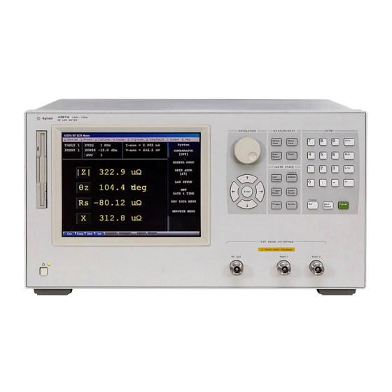
Function Overview Names and Functions of Parts on the Front Panel Names and Functions of Parts on the Front Panel This section describes the names and functions of the individual parts on the 4287A’s front panel. Figure 4-1 4287A front panel 1. -
Page 75: Color Lcd Display
Function Overview Names and Functions of Parts on the Front Panel 3. Color LCD display Almost all of the information required for the measurement value, setup state, result of data processing, result of evaluation, menu bar, softkey labels and indications is shown on the color LCD display. -
Page 76: Instrument State Block (Instr State)
Function Overview Names and Functions of Parts on the Front Panel [Prmtr] key Displays the Prmtrs softkey menu in the softkey area on the right side of the display. These softkeys are used to select the measurement parameter. 6. Instrument state block (INSTR STATE) This block contains a group of hardkeys used to set up the functions to control and manage the comparator, measurement result display, trigger, saving, calling up, and others. -
Page 77: Test Head Interface (Test Head Interface)
Function Overview Names and Functions of Parts on the Front Panel [G/n][M/μ][k/m] and [×1] Pressing one of these keys after the numerical value is keys (unit keys) entered by a numeric entry key confirms your entry of the input numerical value assigned to the unit. In other words, these keys execute the setup. - Page 78 Function Overview Names and Functions of Parts on the Front Panel NOTE To prevent the 4287A from malfunctioning, do not apply DC voltage or DC current to the test head’s DUT port. The capacitor in particular could be charged. When you connect a capacitor, discharge it sufficiently before connecting it to the test fixture that is connected to the test head’s DUT port.
-
Page 79: Names And Functions Of Parts On The Rear Panel
Function Overview Names and Functions of Parts on the Rear Panel Names and Functions of Parts on the Rear Panel The following describes the names and functions of the individual parts on the 4287A’s rear panel. Figure 4-3 4287A rear panel 1. -
Page 80: External Monitor Output Terminal (Video)
Function Overview Names and Functions of Parts on the Rear Panel 3. External monitor output terminal (VIDEO) Connector type: 15-pin VGA connector This terminal is used for connecting to an external color monitor (display unit). Connection of a color monitor through this terminal permits the same information shown on the 4287A’s LCD display to be displayed on the external monitor. -
Page 81: Mini-Din Keyboard Port (Kybd)
An USB mouse is not supported. Use of a mouse other than the specified one may lead to operation error. Be sure to only use the mouse provided by Agilent Technologies. When using a mouse connected to the 4287A, only click the left mouse button. -
Page 82: Names And Functions Of Display Areas On The Lcd Display
Function Overview Names and Functions of Display Areas on the LCD Display Names and Functions of Display Areas on the LCD Display The 4287A LCD display screens include the six types of displays (two measurement displays and four setup displays) explained in Table 4-1. Table 4-1 Types of 4287A displays Display type... - Page 83 Function Overview Names and Functions of Display Areas on the LCD Display Figure 4-4 Switching of six 4287A displays Chapter 4...
-
Page 84: Single Point Measurement Display
Function Overview Names and Functions of Display Areas on the LCD Display Single point measurement display The single point measurement display shown in Figure 4-5 appears when you press the [Meas View] key once or twice. Figure 4-5 Single point measurement display 1. - Page 85 Function Overview Names and Functions of Display Areas on the LCD Display you can turn the rotary knob instead of pressing the keys and then press the rotary knob. Activate the menu bar by pressing the [Alt] key of the keyboard connected to the 4287A and perform any of the following operations (or combined operations): •...
- Page 86 Function Overview Names and Functions of Display Areas on the LCD Display NOTE To directly call up the FREQUENCY softkey menu, click in the measurement frequency area with the mouse. You can use this softkey menu to select the measurement point by the measurement frequency instead of the measurement point number.
- Page 87 Function Overview Names and Functions of Display Areas on the LCD Display 13. Softkeys The softkeys are shown here. To operate the softkeys, first press the [Stml Select] key or key described in “5. Measurement block (MEASUREMENT)” on page 75, or [Prmtr] the keys described in “6.
- Page 88 Function Overview Names and Functions of Display Areas on the LCD Display Display Definition (blue display) The external frequency reference signal is input as ExtRef described in “7. External reference signal input terminal (Ext Ref In, 10 MHz 0 dBm)” on page 80, and the 4287A test signal is phase-locked to that reference signal.
-
Page 89: List Measurement Display
Function Overview Names and Functions of Display Areas on the LCD Display List measurement display The point measurement display shown in Figure 4-6 appears when you press the [Meas View] key once or twice. Figure 4-6 List measurement display 1. Measurement point number This is the number of the measurement point set in the measurement point setup display. - Page 90 Function Overview Names and Functions of Display Areas on the LCD Display • Test signal current monitor value (I-mon) • Measurement frequency (FREQ) • Averaging factor (AVG) • Test signal level (POWER) • DC resistance measurement value (Rdc) 6. Vertical scroll bar You can scroll the table showing the parameters of each measurement point by moving the scroll bar’s thumb vertically while keeping the mouse button left-clicked and then releasing it at the desired location.
-
Page 91: Measurement Point Setup Display
Function Overview Names and Functions of Display Areas on the LCD Display Measurement point setup display When no dialog box is shown, the measurement point setup display (Figure 4-7) can be displayed by pressing the [Setup View] key the required number of times. Figure 4-7 Measurement point setup display 1. - Page 92 Function Overview Names and Functions of Display Areas on the LCD Display the measurement point setup display. If another setup display appears, click this tab with the mouse to get the measurement point setup display. (The same operation can be done with the “View”...
-
Page 93: Calibration Kit Setup Display
Function Overview Names and Functions of Display Areas on the LCD Display Calibration kit setup display When no dialog box is shown, the calibration kit setup display (Figure 4-8) can be displayed by pressing the [Setup View] key the required number of times. Figure 4-8 Calibration kit setup display 1. - Page 94 Function Overview Names and Functions of Display Areas on the LCD Display 4. Open standard value Enter the open standard value. 5. Short standard value Enter the short standard value. 6. Load standard value Enter the load standard value. 7. Circuit model Select one of the three circuit models (Rs-Ls, Ls-Q, or Cp-D) for the load parameter.
-
Page 95: Compensation Kit Setup Display
Function Overview Names and Functions of Display Areas on the LCD Display Compensation kit setup display When no dialog box is shown, the compensation kit setup display (Figure 4-9) can be displayed by pressing the [Setup View] key the required number of times. Figure 4-9 Compensation kit setup display 1. - Page 96 Function Overview Names and Functions of Display Areas on the LCD Display 4. Open standard value Enter the open standard value. 5. Short standard value Enter the short standard value. 6. DC standard value Enter the compensation kit definition for 4287A DC resistance (Rdc) measurement. Chapter 4...
-
Page 97: Bin Sorting Setup Display
Function Overview Names and Functions of Display Areas on the LCD Display Bin sorting setup display When no dialog box is shown, the BIN sorting setup display (Figure 4-10) can be displayed by pressing the [Setup View] key the required number of times. Figure 4-10 Bin sorting setup display 1. - Page 98 Function Overview Names and Functions of Display Areas on the LCD Display 5. Sorting conditions This area is used to set the sorting conditions for each bin. Four sorting conditions are applied to each bin, and the components that meet all four of a bin’s conditions are sorted into that bin.
-
Page 99: 4287A Key Operation Overview
Function Overview 4287A Key Operation Overview 4287A Key Operation Overview Table 4-2 shows the 4287A key operation list. Table 4-2 4287A key operation list Front panel External device MEASURE- Keyboard Mouse Operation MENT/INSTR STATE/ENTRY (Rotary knob) (Arrow keys) block keys Direct switching Press [Setup... - Page 100 Function Overview 4287A Key Operation Overview Table 4-2 4287A key operation list Front panel External device MEASURE- Keyboard Mouse Operation MENT/INSTR STATE/ENTRY (Rotary knob) (Arrow keys) block keys Change of unit Turn clockwise Click on unit in Press [↑][↓] Press drop down list Press [G/n][M/μ]...
-
Page 101: Setting Measurement Conditions
Setting Measurement Conditions This chapter describes how to set the measurement conditions, including measurement frequency and averaging, of the Agilent 4287A RF LCR Meter. The installation of the 4287A must be completed before measurements can be taken. If the installation has not been completed, do this by referring to Chapter 2, “Installation Guide,” on page 17. -
Page 102: How To Preset The 4287A
Setting Measurement Conditions How to Preset the 4287A How to Preset the 4287A To return to the initialized state, called the “preset state,” press the [Preset] key at the lower-right corner of the entry block. NOTE To ensure correct setting, it is best to preset the 4287A before you start a new setting. Chapter 5... -
Page 103: How To Set The Measurement Point
Setting Measurement Conditions How to Set the Measurement Point How to Set the Measurement Point Unlike measuring instruments that allow constant changing of frequency and oscillator levels during measurement, the 4287A requires that all measurement points for subsequent measurements be set before measurement starts. The measurement point is set on the measurement point setup display. -
Page 104: How To Specify Table Number For Setup
Setting Measurement Conditions How to Set the Measurement Point How to specify table number for setup The 4287A has eight tables that allow a maximum of 32 measurement points to be set. To set the measurement point (or to set the calibration kit, compensation kit, or BIN sort), first specify the table number by following the step below. -
Page 105: How To Add Measurement Points
Setting Measurement Conditions How to Set the Measurement Point How to add measurement points The measurement point number 1 of each table (1 to 8) has data consisting of a frequency of 1 MHz, averaging factor of 1, and oscillator level of -13.0 dBm as a preset state. To add new measurement points to those already entered in the specified table, perform the following steps. - Page 106 Setting Measurement Conditions How to Set the Measurement Point Figure 5-4 Addition of measurement frequency NOTE If you add frequency as a new measurement point, the same settings of the averaging factor and oscillator level as those of the previous measurement point are automatically input. If you press the key, key, or rotary knob (...
- Page 107 Setting Measurement Conditions How to Set the Measurement Point Figure 5-5 Example of setting measurement points at intervals of 1 MHz, from 1 MHz to 10 MHz Chapter 5...
-
Page 108: How To Change Frequency Of A Set Measurement Point
Setting Measurement Conditions How to Set the Measurement Point How to change frequency of a set measurement point Change the frequency of an already set measurement point by following these steps: Step 1. Use the mouse to select the frequency cell at the measurement point you want to change. Step 2. -
Page 109: How To Change Averaging Factor
Setting Measurement Conditions How to Set the Measurement Point How to change averaging factor Change the averaging factor of an already set measurement point by following these steps: Step 1. Use the mouse to select the averaging factor cell at the measurement point you want to change. -
Page 110: How To Change Oscillator Level
Setting Measurement Conditions How to Set the Measurement Point How to change oscillator level Change the oscillator level of an already set measurement point by following these steps: Step 1. Use the mouse to select the oscillator level cell at the measurement point you want to change. -
Page 111: How To Change Oscillator Level Setup Unit
Setting Measurement Conditions How to Set the Measurement Point How to change oscillator level setup unit Change the oscillator level setup unit by following these steps: Step 1. Click the mouse in the “Power” column heading to display the menu of the drop-down list box. - Page 112 Setting Measurement Conditions How to Set the Measurement Point Figure 5-10 How to change signal level setup units from dBm to V NOTE The setting resolution of the oscillator level is always 0.1 dB regardless of the set unit. Accordingly, if the oscillator level is entered in V (volt) or A (ampere) units, the set value is automatically converted with 0.1 dB resolution based on the input value.
-
Page 113: Setting Up Dc Resistance (Rdc) Measurement
Setting Measurement Conditions Setting up dc resistance (Rdc) measurement Setting up dc resistance (R ) measurement Turning ON/OFF Follow these steps to turn ON/OFF the R measurement. Step 1. Press the key on the front panel to display the Prmtrs softkey menu. [Prmtr] Step 2. - Page 114 Setting Measurement Conditions Setting up dc resistance (Rdc) measurement Chapter 5...
-
Page 115: Calibration And Compensation
Calibration and Compensation This chapter describes calibration and compensation functions of the Agilent 4287A. Before starting calibration and compensation, set measurement conditions according to Chapter 5, “Setting Measurement Conditions,” on page 101. -
Page 116: Calibration And Compensation Functions
Calibration and Compensation Calibration and Compensation Functions Calibration and Compensation Functions The following describes the calibration and compensation functions of the Agilent Technologies 4287A. Types of calibration and compensation functions The Agilent 4287A has four calibration and compensation functions as shown in Table 6-1. Table 6-1 Overview of Agilent 4287A RF LCR calibration and compensation functions Type of calibration and... -
Page 117: Calibration Reference Plane And Required Calibration And Compensation
Calibration and Compensation Calibration and Compensation Functions *1. These calibration data can normally be used to measure DC resistance (Rdc). If required, a dedicated standard can be prepared to perform a separate DC open/short/load calibration to obtain data for measuring DC resistance. *2. - Page 118 Calibration and Compensation Calibration and Compensation Functions Figure 6-1 and Figure 6-2 show the relationship between the calibration reference plane used and the required calibration/compensation. Figure 6-1 Calibration and compensation when test head coaxial terminal is used as calibration reference plane Chapter 6...
- Page 119 Calibration and Compensation Calibration and Compensation Functions Figure 6-2 Calibration when DUT connection terminal is used as calibration reference plane Chapter 6...
-
Page 120: Calibration And Compensation Procedures Using Dedicated Test Fixture
Calibration and Compensation Calibration and Compensation Procedures Using Dedicated Test Fixture Calibration and Compensation Procedures Using Dedicated Test Fixture The following describes the calibration and compensation procedures to measure the DUT by connecting the Agilent 4287A test head to a dedicated test fixture (e.g. Agilent 16196A) with a 3.5-mm-to-7-mm adapter and a test fixture stand, as illustrated in Figure 6-3. -
Page 121: Test Head Coaxial Terminal Used As Calibration Reference Plane
Calibration and Compensation Calibration and Compensation Procedures Using Dedicated Test Fixture 1. Test head coaxial terminal used as calibration reference plane The following describes the calibration and compensation procedure with a dedicated test fixture when the test head coaxial terminal is used as a calibration reference plane. In this case, the coaxial terminal serving as a calibration reference plane is generally a 7-mm terminal connected by a 3.5-mm-to-7-mm adapter. - Page 122 Calibration and Compensation Calibration and Compensation Procedures Using Dedicated Test Fixture Step 2. Press the key in the softkey menu to display the TABLE No. [ ] softkey TABLE No. [ ] menu. Step 3. In the softkey menu, press the key ( ) corresponding to the TABLE 1 TABLE 8...
- Page 123 Calibration and Compensation Calibration and Compensation Procedures Using Dedicated Test Fixture Figure 6-5 Displaying measured DC resistance value (at calibration data measurement) • To erase all calibration data after measurement is finished, press the Clear Calibration Data button. • To close the dialog box during calibration, press the Close button.
- Page 124 Calibration and Compensation Calibration and Compensation Procedures Using Dedicated Test Fixture Figure 6-6 How to extend the 7-mm connector sleeve Step 2. Firmly connect the open standard (0 S) to the 7-mm terminal on the test head by turning it clockwise as viewed from the top (Figure 6-7).
- Page 125 Calibration and Compensation Calibration and Compensation Procedures Using Dedicated Test Fixture Figure 6-8 How to connect short standard Step 2. Click the button in the calibration window and measure the short calibration data. SHORT Step 3. Turn the short standard counterclockwise viewed from the top and remove the short standard from the 7-mm terminal.
- Page 126 Calibration and Compensation Calibration and Compensation Procedures Using Dedicated Test Fixture Figure 6-10 How to connect load standard Step 3. Click the button in the calibration window and measure the load calibration data. LOAD Step 4. Turn the connector nut outside the load standard counterclockwise as viewed from the top and remove the load standard from the 7-mm terminal.
- Page 127 Calibration and Compensation Calibration and Compensation Procedures Using Dedicated Test Fixture Figure 6-11 How to connect low-loss capacitor Step 2. Click the button in the calibration window and measure the low-loss LOW-LOSS C capacitor data. Step 3. Turn the connector nut outside the low-loss capacitor counterclockwise as viewed from the top and remove it from the 7-mm terminal.
- Page 128 Calibration and Compensation Calibration and Compensation Procedures Using Dedicated Test Fixture Step 2. In the softkey menu, press the key corresponding to the model number (or a fixture name registered by the user) of the test fixture to be used. Softkey Test Fixture (Electrical Length) Agilent 16191A (14.0 mm)
- Page 129 Calibration and Compensation Calibration and Compensation Procedures Using Dedicated Test Fixture • To erase all compensation data after measurement is finished, press the Clear Compensation Data button. • To close the dialog box during compensation, press the button. Close 15. How to select the table range for executing the compensation Select the table range for executing the compensation by making the appropriate setting in area of the Compensation Dialog box window.
- Page 130 Calibration and Compensation Calibration and Compensation Procedures Using Dedicated Test Fixture 18. How to measure short compensation data Follow these steps to measure the short compensation data. Step 1. Set the DUT connection terminal of the dedicated test fixture to the short state. For how to set it to the short state, see the Operation Manual of the test fixture to be used.
-
Page 131: Dut Connection Terminal Used As Calibration Reference Plane
Calibration and Compensation Calibration and Compensation Procedures Using Dedicated Test Fixture 2. DUT connection terminal used as calibration reference plane The following describes the calibration and compensation necessary for using the DUT connection terminal of the dedicated test fixture as a calibration reference plane. As indicated in Table 6-4, only execution of open/short/load calibration is required. - Page 132 Calibration and Compensation Calibration and Compensation Procedures Using Dedicated Test Fixture Figure 6-13 Calibration Dialog box NOTE The following points require attention when performing calibration data measurement. • When you start the calibration data measurement, a bar appears in the Calibration progress indicator box of the dialog box to show how the measurement is progressing.
- Page 133 Calibration and Compensation Calibration and Compensation Procedures Using Dedicated Test Fixture NOTE If you want to use the open state of the test fixture instead of connecting the open standard, set the open state according to the Operation Manual of the test fixture. Step 2.
- Page 134 Calibration and Compensation Calibration and Compensation Procedures Using Dedicated Test Fixture 10. How to end calibration Press the Done button in the Calibration Dialog box to end calibration and close the dialog box. Chapter 6...
-
Page 135: Calibration And Compensation Procedure Without Using Dedicated Test Fixture
Calibration and Compensation Calibration and Compensation Procedure without Using Dedicated Test Fixture Calibration and Compensation Procedure without Using Dedicated Test Fixture The following describes the calibration and compensation procedure when the dedicated test fixture is not used. In this case, the test head coaxial terminal is extended, and the DUT is connected to the tip of the terminal. - Page 136 Calibration and Compensation Calibration and Compensation Procedure without Using Dedicated Test Fixture tables, follow these steps to select the active table. NOTE When performing calibration data measurement for all of the measurement point tables at once, it is not necessary to select individual measurement point tables. Step 1.
- Page 137 Calibration and Compensation Calibration and Compensation Procedure without Using Dedicated Test Fixture 4. How to select the table range for executing the calibration Select the table range for executing the calibration by making the appropriate setting in the area of the Calibration Dialog box window. Select Calibration Table If you select Active table only...
- Page 138 Calibration and Compensation Calibration and Compensation Procedure without Using Dedicated Test Fixture Step 5. Remove the DC short standard and connect the DC load standard. Step 6. Click the button in the calibration window and measure the DC load calibration DC LOAD data.
- Page 139 Calibration and Compensation Calibration and Compensation Procedure without Using Dedicated Test Fixture 14. How to display the compensation dialog box Press the COMPEN DIALOG key in the Cal/Compen softkey menu to display the Compensation Dialog box. Figure 6-15 Compensation Dialog box NOTE The following points require attention when performing compensation data measurement.
- Page 140 Calibration and Compensation Calibration and Compensation Procedure without Using Dedicated Test Fixture 16. How to confirm port extension compensation (fixture selection) Check that the test fixture selected in “13. How to carry out port extension compensation (fixture selection)” on page 138 is indicated in the Fixture Type box of the Compensation Dialog box.
- Page 141 Calibration and Compensation Calibration and Compensation Procedure without Using Dedicated Test Fixture 21. How to end compensation Press the Done button in the Compensation Dialog box to end compensation and close the dialog box. Chapter 6...
-
Page 142: Dut Connection Terminal Used As Calibration Reference Plane
Calibration and Compensation Calibration and Compensation Procedure without Using Dedicated Test Fixture 2. DUT connection terminal used as calibration reference plane When you want to use the DUT connection terminal as a calibration reference plane, connect the working standard to the DUT connection terminal to perform open/short/load calibration (Table 6-6). - Page 143 Calibration and Compensation Calibration and Compensation Procedure without Using Dedicated Test Fixture Figure 6-16 Calibration Dialog box NOTE The following points require attention when performing calibration data measurement. • When you start the calibration data measurement, a bar appears in the Calibration progress indicator box of the dialog box to show how the measurement is progressing.
- Page 144 Calibration and Compensation Calibration and Compensation Procedure without Using Dedicated Test Fixture Step 2. Click the button in the calibration window and measure the open calibration data. OPEN 6. How to measure short calibration data Measure the short calibration data as follows: Step 1.
-
Page 145: How To Define Calibration Kit
Calibration and Compensation How to Define Calibration Kit How to Define Calibration Kit Before starting calibration, the characteristic values of the open/short/load standards used for calibration must be set in advance. For the Agilent 4287A, define the calibration kit by using the circuit model shown in Figure 6-17. - Page 146 Calibration and Compensation How to Define Calibration Kit Figure 6-18 Calibration kit setup window Step 2. Specify the table number to define a calibration kit by following the description in “How to specify table number for setup” on page 104. Step 3.
-
Page 147: How To Define Compensation Kit
Calibration and Compensation How to Define Compensation Kit How to Define Compensation Kit Before starting compensation, characteristic values of the open/short standards used for compensation must be set in advance. For the Agilent 4287A, define the compensation kit by using the circuit model shown in Figure 6-19. - Page 148 Calibration and Compensation How to Define Compensation Kit Figure 6-20 Compensation kit setup window Step 2. Specify the table number to define a compensation kit by following the description in “How to specify table number for setup” on page 104. Step 3.
-
Page 149: Registering The Electrical Length Of Unregistered Test Fixtures
Calibration and Compensation Registering the Electrical Length of Unregistered Test Fixtures Registering the Electrical Length of Unregistered Test Fixtures For the 4287A, the electrical lengths (from 7-mm terminal to DUT connection plane) of the test fixtures 16191A, 16192A, 16193A, 16194A, 16196A, 16196B, and 16196C are registered in advance. - Page 150 Calibration and Compensation Registering the Electrical Length of Unregistered Test Fixtures Figure 6-22 User Fixture Label dialog box Step 5. Enter the label (name) of the newly registered test fixture in the label space at the top of the dialog box. Chapter 6...
-
Page 151: Preventing Mistakes During Execution Of Calibration And Compensation
Calibration and Compensation Preventing Mistakes During Execution of Calibration and Compensation Preventing Mistakes During Execution of Calibration and Compensation Setting limit values for the DC resistance (Rdc) measurement value when calibration and compensation are executed makes it possible to detect an improperly attached standard during calibration or any abnormality with the measurement terminals during compensation. -
Page 152: How To Execute Calibration And Compensation
Calibration and Compensation Preventing Mistakes During Execution of Calibration and Compensation Figure 6-24 DC resistance (Rdc) limit check turned ON Step 5. In the box in the area of the Short-Load Rdc Limit (Calibration) Calibration/Compensation Wizard Setting dialog box, enter the limit values for DC resistance measurement for short calibration and load calibration. - Page 153 Calibration and Compensation Preventing Mistakes During Execution of Calibration and Compensation Figure 6-25 Checking calibration and compensation task errors with DC resistance measurement value Chapter 6...
- Page 154 Calibration and Compensation Preventing Mistakes During Execution of Calibration and Compensation Chapter 6...
-
Page 155: Executing Measurements And Displaying Results
Executing Measurements and Displaying Results This chapter describes how measurements are performed and how the measurement results are displayed by the 4287A. -
Page 156: Connecting The Dut
Executing Measurements and Displaying Results Connecting the DUT Connecting the DUT When using a dedicated test fixture, see the operation manual of the test fixture for details on how to connect the DUT. Chapter 7... -
Page 157: Selecting Single Point Measurement Or List Measurement
Executing Measurements and Displaying Results Selecting Single Point Measurement or List Measurement Selecting Single Point Measurement or List Measurement When the setup display appears, press the key on the front panel to display [Meas View] either the single point measurement display (Figure 7-1) or the list measurement display (Figure 7-2). -
Page 158: How To Select The Measurement Point Table
Executing Measurements and Displaying Results How to Select the Measurement Point Table How to Select the Measurement Point Table Follow these steps to select the measurement point table according to “How to Set the Measurement Point” on page 103. Step 1. Press the [Stml Select] key on the front panel to display the Stml Select softkey menu. -
Page 159: Selection Of Measurement Point
Executing Measurements and Displaying Results Selection of Measurement Point Selection of Measurement Point Select the measurement point in the single point measurement display as follows: Step 1. Press the key in the measurement block to display the Stml Select softkey [Stim Select] menu. -
Page 160: Selection Of Measurement Parameters In Single Point Measurement Display
Executing Measurements and Displaying Results Selection of Measurement Parameters in Single Point Measurement Display Selection of Measurement Parameters in Single Point Measurement Display In the single point measurement display, a maximum of four parameters can be simultaneously displayed for the selected measurement point. Follow these steps to set the measurement parameters. - Page 161 Executing Measurements and Displaying Results Selection of Measurement Parameters in Single Point Measurement Display selection softkey menu for each measurement parameter number by directly clicking on the large letters that symbolize each of the four parameters (the measurement parameter area of “16.
-
Page 162: Selection Of Display Parameters In List Measurement Display
Executing Measurements and Displaying Results Selection of Display Parameters in List Measurement Display Selection of Display Parameters in List Measurement Display In the list measurement display, a maximum of four parameters can be simultaneously displayed for the listed measurement points. Follow these steps to set the list display parameters. - Page 163 Executing Measurements and Displaying Results Selection of Display Parameters in List Measurement Display Example of setting with measurement frequency, |Z|, θz (deg), and test signal current Figure 7-3 level monitor values used as list display parameters Chapter 7...
-
Page 164: Setting How The Instrument Displays Measurement Results
Executing Measurements and Displaying Results Setting How the Instrument Displays Measurement Results (Enabling/Disabling Deviation Measurement Mode) Setting How the Instrument Displays Measurement Results (Enabling/Disabling Deviation Measurement Mode) You can have the instrument display measurement results as absolute values or as deviations relative to the reference value (deviation measurement mode). - Page 165 Executing Measurements and Displaying Results Setting How the Instrument Displays Measurement Results (Enabling/Disabling Deviation Measurement Mode) Follow these steps to set the deviation measurement mode. Step 1. Press the key in the measurement block to display the parameter setup softkey [Prmtr] menu in the list measurement display.
-
Page 166: Hiding The Screen Display
Executing Measurements and Displaying Results Hiding the Screen Display Hiding the Screen Display The screen display of measurement results, softkey menu and instrument status can be hidden with only the menu bar left visible on the screen. If you hide the screen display, it is not updated;... -
Page 167: Turning On/Off Update The Lcd Display View
Executing Measurements and Displaying Results Turning ON/OFF Update the LCD Display View Turning ON/OFF Update the LCD Display View The update function of the LCD display view can be turned ON/OFF. NOTE For how to perform the instruction “press the key (softkey) in the softkey menu” mentioned in the procedure, see “13. - Page 168 Executing Measurements and Displaying Results Turning ON/OFF Update the LCD Display View Figure 7-6 View when the update of the screen display is turned off Table 7-2 Time of each task (typical values) DISP:ON Measurement sequence DISP:OFF UPDATE:ON UPDATE:OFF Setup time of READ? 5.3 ms 33.0 ms 5.6 ms...
- Page 169 Executing Measurements and Displaying Results Turning ON/OFF Update the LCD Display View screen regardless of which command is executed. 2. The display time is much shorter for the list measurement display than for the single point measurement display 3. The display time becomes shorter as the number of display parameters decreases. 4.
- Page 170 Executing Measurements and Displaying Results Turning ON/OFF Update the LCD Display View Chapter 7...
-
Page 171: Sorting According To Measurement Results
Sorting According to Measurement Results This chapter describes the BIN sort functions for sorting parts based on the obtained measurements. -
Page 172: Overview Of Bin Sort Function
Overview of BIN Sort Function Overview of BIN Sort Function The BIN sort function of the Agilent Technologies 4287A is designed to determine, based on the obtained measurement data, the BIN where a DUT (device under test) should be placed according to the preset sorting conditions. By using this function, the result is indicated on the display and signals are sent to the handler interface. - Page 173 Sorting According to Measurement Results Overview of BIN Sort Function Figure 8-2 Parts sorting by automatic sorter Chapter 8...
-
Page 174: Concept Of Setting 4287A Bins
Sorting According to Measurement Results Overview of BIN Sort Function Concept of setting 4287A BINs Each BIN sorting condition based on the obtained measurements is set according to the principles given below and illustrated inTable 8-1. • A maximum of 13 BINs can be set for each measurement point table (unused BINs are turned off). - Page 175 Sorting According to Measurement Results Overview of BIN Sort Function Table 8-1 Concept of 4287A BIN sort setting (set items for each table) Sorting condition 1 Sorting condition 2 Sorting condition 3 Sorting condition 4 Measurement point Measurement point Measurement point Measurement point number number...
-
Page 176: Internal Flow Of Bin Sort Judgment
Sorting According to Measurement Results Overview of BIN Sort Function Internal flow of BIN sort judgment The BIN sort judgment is made according to the flow shown in Figure 8-3. Figure 8-3 Internal flow of BIN sort judgment by 4287A Chapter 8... -
Page 177: Setting Measurement Point
Sorting According to Measurement Results Setting Measurement Point Setting Measurement Point The following describes how to set the measurement point for BIN sorting under each sorting condition (1 to 4). NOTE To set the conditions for BIN sorting, the required measurement points should have been set in the measurement point setup display. - Page 178 Sorting According to Measurement Results Setting Measurement Point Figure 8-5 Selection of measurement point as sorting condition 1 NOTE The drop-down list box allows a maximum of ten lines to appear in one display. If there are more than ten lines, click on in the upper-right or in the lower-right part of the list box or use the scroll thumb to scroll the list.
-
Page 179: Setting Measurement Parameter
Sorting According to Measurement Results Setting Measurement Parameter Setting Measurement Parameter After setting the measurement point number, select the measurement parameter for BIN sorting. NOTE Similar to setting the measurement point, selecting the measurement parameter in BIN sorting is independent of the selection of the measurement parameter in the measurement display (single point measurement or list measurement). - Page 180 Sorting According to Measurement Results Setting Measurement Parameter Figure 8-6 Selection of measurement parameter for sorting condition 1 Chapter 8...
-
Page 181: Setting Limit Mode And Reference Value
Sorting According to Measurement Results Setting Limit Mode and Reference Value Setting Limit Mode and Reference Value Setting limit mode This procedure determines the format used to set the upper and lower limits of the measurement values for BIN sorting. Step 1. -
Page 182: Setting Reference Value
Sorting According to Measurement Results Setting Limit Mode and Reference Value Setting reference value When you select percentage mode ( ) or deviation mode ( ) as the limit mode, you PCNT must set the reference value (Nominal). NOTE When you select absolute mode ( ) as the BIN limit mode, you do not need to set the reference value (nominal). -
Page 183: Setting Bin Range
Sorting According to Measurement Results Setting BIN Range Setting BIN Range Set the actual BIN range after setting the BIN range setting conditions according to “Setting Measurement Point” on page 177), “Setting Measurement Parameter” on page 179, and “Setting Limit Mode and Reference Value” on page 181. Setting upper limit value Follow these steps to set the BIN upper limit value. -
Page 184: Setting Lower Limit Value
Sorting According to Measurement Results Setting BIN Range Setting lower limit value Follow these steps to set the lower limit value after setting the upper limit value of the BIN as follows: Step 1. Click with the mouse in the cell corresponding to the column of the desired sorting condition (one of conditions 1 to 4) on the row of the lower limit value of the BIN to be set. -
Page 185: Selecting Bin Range Mode
Sorting According to Measurement Results Setting BIN Range Selecting BIN range mode You can select whether the BIN range should be inside or outside of the set limit values (upper and lower limit values) or whether the BIN range should cover the entire range regardless of the limit values. -
Page 186: Setting Bin On And Off
Sorting According to Measurement Results Setting BIN On and Off Setting BIN On and Off In the presetting, all BINs are off (inactive), and the BIN is regarded as non-existent. This requires the BIN to be turned on (activated) either before or after setting the BIN range to make the new settings active. -
Page 187: Setting Faulty Bin (Out Of Good Bins)
Sorting According to Measurement Results Setting Faulty BIN (OUT OF GOOD BINS) Setting Faulty BIN (OUT OF GOOD BINS) You can predetermine that BINs following the desired BIN number are faulty. If a BIN is evaluated as faulty by BIN sorting, the result of OUT_OF_GOOD_BINS as well as the BIN number is output to the handler interface. -
Page 188: Setting Upper And Lower Limit Values For Dc Resistance Measurement
Sorting According to Measurement Results Setting Upper and Lower Limit Values for DC Resistance Measurement Setting Upper and Lower Limit Values for DC Resistance Measurement When the DC resistance (Rdc) measurement is activated, the 4287A starts DC resistance measurement before impedance measurement. In this case, pass/fail evaluation is made according to the preset test limit after DC resistance measurement. -
Page 189: Turning On Bin Sorting And Displaying The Result
Sorting According to Measurement Results Turning On BIN Sorting and Displaying the Result Turning On BIN Sorting and Displaying the Result When BIN sorting setup is completed, follow these steps to turn on the BIN sorting function. Step 1. Press the key in the Instrument State Block on the front panel to display the [System] System softkey menu. -
Page 190: Bin Count Function
Sorting According to Measurement Results Bin Count Function Bin Count Function Effective from The Bin Count function counts the frequency by incrementing the bin count corresponding Firmware Rev. 1.20 to the Bin Sorting result by 1 each time measurement ends. The frequency of each bin can be viewed on the display when necessary. -
Page 191: Initializing The Contents Of The Bin Counts To Zero (Resetting The Counter)
Sorting According to Measurement Results Bin Count Function Figure 8-16 Bin Count Results dialog box NOTE To close the Bin Count Results dialog box, press the button. The BIN Count results listed in the dialog box are those obtained when you pressed the softkey. -
Page 192: Example Of Settings For Bin Sorting
Sorting According to Measurement Results Example of Settings for BIN Sorting Example of Settings for BIN Sorting The following introduces an example of setting an actual BIN sort setting table. The sorting conditions to be set are shown in Table 8-2. Table 8-2 Sorting conditions Condition 1... -
Page 193: Setting The Measurement Point Number, Measurement Parameter, And Bin Range Setting Mode For Condition 1
Sorting According to Measurement Results Example of Settings for BIN Sorting Setting the measurement point number, measurement parameter, and BIN range setting mode for Condition 1 Step 1. Press the key in the instrument state block (INSTR STATE) on the front panel to [Cmptr] display the BIN sorting setup display (Figure 8-17). - Page 194 Sorting According to Measurement Results Example of Settings for BIN Sorting Figure 8-18 Setting the measurement point number (Stimulus) for Condition 1 Step 3. Set the measurement parameter for Condition 1 to Ls. Figure 8-19 Setting the measurement parameter for Condition 1 Step 4.
- Page 195 Sorting According to Measurement Results Example of Settings for BIN Sorting Figure 8-20 Setting the limit setting mode (Mode) for Condition 1 d. Click the reference value (Nominal) cell below the limit setting mode (Mode) cell. e. Press the [5], [0] and [G/n] keys in the entry block on the front panel sequentially to input 50 nH as the reference value.
-
Page 196: Setting The Measurement Point Number, Measurement Parameter, And Bin Range Setting Mode For Condition 2
Sorting According to Measurement Results Example of Settings for BIN Sorting Setting the measurement point number, measurement parameter, and BIN range setting mode for Condition 2 Step 1. In the same manner as for Condition 1, set the measurement point number for Condition 2 by following this procedure. -
Page 197: Setting The Measurement Value Range For Sorting Into Bin 1 To Bin 3
Sorting According to Measurement Results Example of Settings for BIN Sorting Figure 8-23 Setting the measurement parameter (Parameter) for Condition 2 NOTE The setting mode for the range for sorting in Condition 2 is not changed from the default setting “ABS” (absolute value setting). When set with an absolute value, the reference value is not required and “--------”... - Page 198 Sorting According to Measurement Results Example of Settings for BIN Sorting Figure 8-24 Setting the upper limit value for Condition 1 of BIN 1 Step 2. Set the lower limit measurement value for sorting into BIN 1 for Condition 1 by following this procedure.
- Page 199 Sorting According to Measurement Results Example of Settings for BIN Sorting Figure 8-26 Setting the BIN range mode for sorting into BIN 1 for Condition 1 Step 4. Set the upper limit measurement value for sorting into BIN 1 for Condition 2 by following this procedure.
- Page 200 Sorting According to Measurement Results Example of Settings for BIN Sorting NOTE Instead of setting the upper limit to infinite, 1G is entered as a sufficiently large value. The In/Out cell is left unchanged in the default setting “In” (the BIN range is between the upper limit and lower limit).
- Page 201 Sorting According to Measurement Results Example of Settings for BIN Sorting Figure 8-29 Setting the BIN range mode of Condition 2 of BIN 2 Step 7. Set the BIN 1 setting to On. Figure 8-30 BIN 1 turned to ON setting Step 8.
-
Page 202: Out Of Good Bins Setting
Sorting According to Measurement Results Example of Settings for BIN Sorting Figure 8-31 BIN 2 and BIN 3 sorting condition settings OUT OF GOOD BINS setting Following these steps to set OUT OF GOOD BINS. Step 1. Click with the mouse “2. Edit” in the menu bar to display the pull-down menu. Step 2. - Page 203 Sorting According to Measurement Results Example of Settings for BIN Sorting Figure 8-32 OUT OF GOOD BINS setting The GOOD BINS line is drawn between BIN 3 and BIN 4 as shown in Figure 8-33. In accordance with this setting, measurement results that do not meet the conditions set for BIN 1 to BIN 3 are judged to be OUT OF GOOD BINS.
-
Page 204: Displaying The Bin Sorting Results
Sorting According to Measurement Results Example of Settings for BIN Sorting Displaying the BIN sorting results Following these steps to display the BIN sort result on the LCD display. Step 1. Press the [System] key on the front panel to display the System softkey menu. Step 2. -
Page 205: Obtaining Statistical Data On Measurement Results
Obtaining Statistical Data on Measurement Results This chapter describes the functions for calculating and displaying statistical data following continuous recording of measurement results. -
Page 206: Overview Of Functions For Statistical Analysis
Obtaining Statistical Data on Measurement Results Overview of Functions for Statistical Analysis Overview of Functions for Statistical Analysis Agilent 4287A’s functions for statistical analysis allow you to store the required values of measurement results (four measurement parameters, test signal voltage level monitor value, test signal current level monitor value, DC resistance measurement value) in the order of measurement internally in the unit. -
Page 207: Data Logging For Statistical Analysis
Obtaining Statistical Data on Measurement Results Data Logging for Statistical Analysis Data Logging for Statistical Analysis Perform the following steps to log the data to be used in statistical analysis. Step 1. From the seven parameters (measurement parameter 1, measurement parameter 2, measurement parameter 3, measurement parameter 4, test signal voltage level monitor value (I-mon), test signal current level monitor value (V-mon), and DC resistance measurement value (Rdc)), select the parameters for statistical analysis and display them... - Page 208 Obtaining Statistical Data on Measurement Results Data Logging for Statistical Analysis Step 6. Activate the measurement trigger and execute measurement the required number of times. NOTE When the trigger mode is free run, data logging starts at the time the START LOGGING is selected in Step 6.
-
Page 209: Executing Statistical Analysis And Displaying Results
Obtaining Statistical Data on Measurement Results Executing Statistical Analysis and Displaying Results Executing Statistical Analysis and Displaying Results The following procedure is used to execute statistical analysis and display results. Step 1. Press the key on the measurement block of the front panel to display the Prmtrs [Prmtr] softkey menu. -
Page 210: Saving Measurement Data For Statistical Analysis
Obtaining Statistical Data on Measurement Results Saving Measurement Data for Statistical Analysis Saving Measurement Data for Statistical Analysis The following procedure can be used to save measurement data for statistical analysis to the 4287A’s hard disk or to a floppy disk. Step 1. - Page 211 Obtaining Statistical Data on Measurement Results Saving Measurement Data for Statistical Analysis Figure 9-4 File Name input window b. Click the letter keys to enter the filename. c. Click the key to complete the filename input. Enter Function (Letter and symbol keys) To enter the alphabetic letter or symbol shown on the key face at the position of the cursor on the input line.
- Page 212 Obtaining Statistical Data on Measurement Results Saving Measurement Data for Statistical Analysis Chapter 9...
-
Page 213: Storing And Retrieving 4287A Internal Information And File Management
Storing and Retrieving 4287A Internal Information and File Management This chapter describes the methods used for storing and retrieving 4287A internal information (setting statuses, results of statistical analyses, screen displays) as well as file management. -
Page 214: Saving Setting Status
Storing and Retrieving 4287A Internal Information and File Management Saving Setting Status Saving Setting Status The following procedure can be used to save any of several setting statuses of the 4287A on a storage device (built-in nonvolatile memory or floppy disk). Step 1. -
Page 215: Entering The Filename Using The Mouse
Storing and Retrieving 4287A Internal Information and File Management Saving Setting Status Entering the Filename using the Mouse When using the mouse for entering the filename, follow this procedure. Step 1. Click the Input from the front panel button to display the file name input window (Figure 10-2). -
Page 216: Saving Screen Displays
Storing and Retrieving 4287A Internal Information and File Management Saving Screen Displays Saving Screen Displays Follow this procedure to save the 4287A’s current screen display on a storage device (built-in nonvolatile memory or floppy disk) in the Windows bitmap format (.bmp). Step 1. -
Page 217: Saving The List Measurement Display In Csv Format
Storing and Retrieving 4287A Internal Information and File Management Saving the List Measurement Display in CSV Format Saving the List Measurement Display in CSV Format The following procedure can be used to save the setting values and measurement result list components of the list measurement display of the 4287A on a storage device (built-in nonvolatile memory or floppy disk) in the CSV format (.csv). -
Page 218: Example Of The Saved List Measurement Display Data (Csv Format)
Storing and Retrieving 4287A Internal Information and File Management Saving the List Measurement Display in CSV Format Example of the Saved List Measurement Display Data (CSV format) The saved CSV-format data is a text file. This file can be opened using a text editor in a PC(Personal Computer). -
Page 219: Saving The Setup Table (Measurement Point, Calibration Kit, Compensation Kit) In Csv Format
Storing and Retrieving 4287A Internal Information and File Management Saving the Setup Table (Measurement point, Calibration kit, Compensation kit) in CSV Format Saving the Setup Table (Measurement point, Calibration kit, Compensation kit) in CSV Format The following procedure can be used to save the setting values and measurement result list components of the measurement point setup table, calibration kit setup table and compensation kit setup table of the 4287A on a storage device (built-in nonvolatile memory or floppy disk) in the CSV format (.csv). -
Page 220: Example Of The Saved Setup Table Data (Csv Format)
Storing and Retrieving 4287A Internal Information and File Management Saving the Setup Table (Measurement point, Calibration kit, Compensation kit) in CSV Format Example of the Saved Setup Table Data (CSV format) The saved CSV-format data is a text file. This file can be opened using a text editor in a PC(Personal Computer). -
Page 221: Saving The Bin Sorting Setup Table In Csv Format
Storing and Retrieving 4287A Internal Information and File Management Saving the BIN Sorting Setup Table in CSV Format Saving the BIN Sorting Setup Table in CSV Format The following procedure can be used to save the setting values and measurement result list components of the BIN sorting setup table of the 4287A on a storage device (built-in nonvolatile memory or floppy disk) in the CSV format (.csv). -
Page 222: Example Of The Saved Bin Sorting Setup Table Data (Csv Format)
Storing and Retrieving 4287A Internal Information and File Management Saving the BIN Sorting Setup Table in CSV Format Example of the Saved BIN Sorting Setup Table Data (CSV format) The saved CSV-format data is a text file. This file can be opened using a text editor in a PC(Personal Computer). - Page 223 Storing and Retrieving 4287A Internal Information and File Management Saving the BIN Sorting Setup Table in CSV Format The CSV-format data can be displayed with a formatted style in a spreadsheet application software. Figure 10-9 shows the CSV data (Table 10-3) displayed in Microsoft Excel. Figure 10-9 Display the CSV-format BIN Sorting Setup Table Data in the spreadsheet Chapter 10...
- Page 224 Storing and Retrieving 4287A Internal Information and File Management Saving the BIN Sorting Setup Table in CSV Format Chapter 10...
-
Page 225: Setting And Using The Control And Management Facilities
Setting and Using the Control and Management Facilities This chapter describes the methods for setting and using the control and management facilities for the 4287A functions not directly related to measurement results and analysis. -
Page 226: Checking And Editing The Gpib Address
Setting and Using the Control and Management Facilities Checking and Editing the GPIB Address Checking and Editing the GPIB Address The 4287A can be controlled by an external controller through the GPIB (General Purpose Interface Bus) interface. The following procedure is used for checking and editing the GPIB address. - Page 227 Setting and Using the Control and Management Facilities Checking and Editing the GPIB Address NOTE The GPIB address can be set using whole numbers from 0 to 30. Step 4. Perform the following operations to complete or cancel the input of the GPIB address. Operation Function Front panel...
-
Page 228: Configuring The Network
Setting and Using the Control and Management Facilities Configuring the Network Configuring the Network NOTE When you use the 4287A by connecting it to your LAN, consult your network administrator and make the setting of the LAN correctly. This section describes how to set the following basic items necessary to connect the 4287A to the LAN (Local Area Network). -
Page 229: Setting Ip Address
Setting and Using the Control and Management Facilities Configuring the Network Step 5. When switching from disable to enable: Double-click the Local Area Connection icon (1 in Figure 11-2) in the Network and Dial-up connections window to enable the network connection function. Step 6. - Page 230 Setting and Using the Control and Management Facilities Configuring the Network Step 5. The Local Area Connection Properties dialog box (Figure 11-3) appears. Select (highlight) Internet Protocol (TCP/IP) (1 in Figure 11-3) and then click the Properties button (2 in Figure 11-3).
-
Page 231: Specifying Computer Name
Setting and Using the Control and Management Facilities Configuring the Network Step 7. In the Internet Protocol (TCP/IP) Properties dialog box, click the button (6 in Figure 11-4). Step 8. In the Local Area Connection Properties dialog box, click the button (3 in Figure 11-3). - Page 232 Setting and Using the Control and Management Facilities Configuring the Network Step 5. The Identification Changes dialog box (Figure 11-6) appears. Enter the computer name in Computer Name box (1 in Figure 11-6). Figure 11-6 Identification Changes dialog box Step 6. The Network Identification dialog box (Figure 11-7) appears. Click the button.
-
Page 233: Setting The Built-In Speaker (Beep Sound)
Setting and Using the Control and Management Facilities Setting the Built-in Speaker (Beep Sound) Setting the Built-in Speaker (Beep Sound) The 4287A is provided with a built-in speaker for emitting beep sounds. The beep sounds serve two functions as shown in Table 11-1. Table 11-1 4287A beep functions Type... -
Page 234: Switching The Beep Sound That Indicates The Bin Sort Function Result (Pass Or Fail)
Setting and Using the Control and Management Facilities Setting the Built-in Speaker (Beep Sound) Step 2. Press the key in the softkey menu to display the BEEPER MENU softkey BEEPER MENU menu. Step 3. Press the key in the softkey menu to turn the warning beep ON or OFF BEEP WARN [ ] (the setting toggles with each press of the button). -
Page 235: Locking The Front Panel Keys, Keyboard And Mouse
Setting and Using the Control and Management Facilities Locking the Front Panel Keys, Keyboard and Mouse Locking the Front Panel Keys, Keyboard and Mouse You can lock the operation of any of the input devices, including the 4287A front panel keys, the attached keyboard, and the attached mouse. -
Page 236: Locking The Keyboard
Setting and Using the Control and Management Facilities Locking the Front Panel Keys, Keyboard and Mouse Locking the keyboard All of the keys on the keyboard connected to the 4287A can be made inoperative by following the procedure described below. NOTE Once the keyboard has been locked, the locked condition cannot be released until the power has been turned OFF and then ON again. -
Page 237: Locking The Mouse
Setting and Using the Control and Management Facilities Locking the Front Panel Keys, Keyboard and Mouse Locking the mouse The mouse connected to the 4287A can be made inoperative. NOTE After the mouse has been locked, it cannot be used to return the mouse lock to OFF. For how to perform the instruction “press the key (softkey) in the softkey menu”... -
Page 238: Locking The Front Panel Keys, Keyboard And Mouse Simultaneously
Setting and Using the Control and Management Facilities Locking the Front Panel Keys, Keyboard and Mouse Locking the front panel keys, keyboard and mouse simultaneously With the exception of the standby switch ( ), all of the front panel keys, the attached keyboard, and the attached mouse can be made inoperative at the same time. -
Page 239: Turning Off The Lcd Display's Backlight
Setting and Using the Control and Management Facilities Turning OFF the LCD Display’s Backlight Turning OFF the LCD Display’s Backlight The following procedure can be used to turn off the backlight (illumination) of the 4287A’s LCD display. Turning off the illumination helps extend the service life of the backlight when the unit is used in continuous operation. -
Page 240: System Recovery
Setting and Using the Control and Management Facilities System Recovery System Recovery By executing system recovery, you can return the system of the 4287A (the Windows operating system and the firmware) to the factory state (at the time of purchase Types of system recoveries The following two types of system recoveries are available. -
Page 241: Procedure To Execute System Recovery
Setting and Using the Control and Management Facilities System Recovery Procedure to execute system recovery This section describes how to return the contents of the C drive to the factory state. NOTE You need the keyboard for this operation. Step 1. Shut down the 4287A. Step 2. - Page 242 Step 7. The message as shown below appears. Press of the keyboard. If you want to cancel the factory recovery, press here. Agilent Technologies System Utilities Recovery & Backup Options Choose One of the following: _________________________________________________________________ 1. Recover Factory Backup Image 2.
- Page 243 Setting and Using the Control and Management Facilities System Recovery Step 8. The message as shown below appears. Press of the keyboard. If you want to cancel the system recovery, press here. You chose to Restore your system by installing the original factory installed OS and system software.
-
Page 244: Procedure To Create The User Backup Image
Setting and Using the Control and Management Facilities System Recovery Procedure to create the user backup image This section describes how to create the user backup image. The C drive contents saved in this creation are recalled when the user recovery function is executed. NOTE This function is available when the volume label on the hard disk is IZ202 or higher. - Page 245 Step 7. The message as shown below appears. Press of the keyboard. If you want to cancel the create user backup image, press here. Agilent Technologies System Utilities Recovery & Backup Options Choose One of the following: _________________________________________________________________ 1. Recover Factory Backup Image 2.
- Page 246 Setting and Using the Control and Management Facilities System Recovery Step 8. The message as shown below appears. Press of the keyboard. If you want to cancel the create user backup image, press here. You chose to create a backup image file of your system. The system will perform a quick integrity check of the file structure on the C: Drive.
-
Page 247: Procedure To Execute The User Recovery Function
Setting and Using the Control and Management Facilities System Recovery Procedure to execute the user recovery function Returns the contents of the C drive to a user-specified state. To use this function, you must create the user backup image in advance. For more information, see the description “Procedure to create the user backup image”... - Page 248 Step 7. The message as shown below appears. Press of the keyboard. If you want to cancel the user recovery, press here. Agilent Technologies System Utilities Recovery & Backup Options Choose One of the following: _________________________________________________________________ 1. Recover Factory Backup Image 2.
- Page 249 Setting and Using the Control and Management Facilities System Recovery Step 8. The message as shown below appears. Press of the keyboard. If you want to cancel the user recovery, press here. You chose to recover your own system backup image file. WARNING: Press C to Continue only if you are sure that you want to proceed.
- Page 250 Setting and Using the Control and Management Facilities System Recovery Chapter 11...
-
Page 251: Specifications And Supplemental Performance Characteristics
Specifications and Supplemental Performance Characteristics... - Page 252 Specifications and Supplemental Performance Characteristics Specifications describe the instrument’s warranted performance over the temperature range of 5 °C to 40 °C (except as noted). Supplemental performance characteristics are intended to provide helpful information for using certain non-warranted performance parameters with the instrument. These are denoted as SPC (supplemental performance characteristics), typical, or nominal.
-
Page 253: Basic Measurement Characteristics
Specifications and Supplemental Performance Characteristics Basic Measurement Characteristics Basic Measurement Characteristics Measurement parameters |Z|, |Y|, Ls, Lp, Cs, Cp, Rs, Rp, X, G, B, D, Q, θz [°], Impedance parameters θz [rad], θy [°], θy [rad] (A maximum of four parameters can be displayed at one time.) Measurement range Measurement range... - Page 254 Specifications and Supplemental Performance Characteristics Basic Measurement Characteristics Resolution 0.1 dB Uncertainty Cable length: 1 m Power (when 50 Ω LOAD is connected to test port) Frequency ≤ 1 GHz ±2 dB(23 ± 5°C) ±4 dB(5°C to 40°C) ±3 dB(23 ±5°C) Frequency >...
-
Page 255: Measurement Accuracy
Specifications and Supplemental Performance Characteristics Basic Measurement Characteristics Output Impedance 50 Ω (nominal) Output Impedance Measurement accuracy Conditions for Defining Accuracy 23 ±5°C Temperature Accuracy-specified plane 7-mm connector of 3.5-mm-to-7-mm adapter connected to 3.5-mm terminal of test heads Measurement Uncertainty When OPEN/SHORT/LOAD calibration is performed: ±... - Page 256 Specifications and Supplemental Performance Characteristics Basic Measurement Characteristics When OPEN/SHORT/LOAD/LOW- LOSS C calibration is performed (SPC): ± |Z|,|Y| θ ± -------- - [rad] L, C, X, B ± R, G ± < -------- - -------- - ...
- Page 257 Specifications and Supplemental Performance Characteristics Basic Measurement Characteristics ±1.2 [%] Frequency > 500 MHz, ≤ 1 GHz ±2.5 [%] Frequency > 1 GHz, ≤ 1.8 GHz ±5 [%] Frequency > 1.8 GHz, ≤ 3 GHz Oscillator level < −33 Frequency ≥ 1 MHz, ±1 [%] ≤...
- Page 258 Specifications and Supplemental Performance Characteristics Basic Measurement Characteristics Oscillator level < −33 ± (100 + 0.15 × F) [μS] (F: Frequency [MHz]) At the following points, measurement error may exceed the specifications described here due to the 4287A’s spurious characteristics: 109.7 MHz, 153.6 MHz, 177.2 MHz, 256.0 MHz, 329.1 MHz, 460.8 MHz, 768.0 MHz Examples of Calculated Impedance Measurement Accuracy Oscillator Level ≥...
- Page 259 Specifications and Supplemental Performance Characteristics Basic Measurement Characteristics Oscillator Level ≥ −33 dBm, Averaging Factor ≤ 7, Temperature Deviation ≤ 5°C Figure 12-2 Chapter 12...
- Page 260 Specifications and Supplemental Performance Characteristics Basic Measurement Characteristics Oscillator Level < −33 dBm, Temperature Deviation ≤ 5°C Figure 12-3 Chapter 12...
-
Page 261: Timing Chart And Measurement Time (Spc)
Specifications and Supplemental Performance Characteristics Basic Measurement Characteristics Timing chart and measurement time (SPC) Timing Chart of Handler Interface Signal (SPC) Figure 12-4 Timing Chart of Handler Interface Chapter 12... - Page 262 Specifications and Supplemental Performance Characteristics Basic Measurement Characteristics Table 12-1 Value T1 through T (Typical) Test Condition Timing Name Screen Setting Display Compa Min. Median Meas. rator 2 μs Trigger pulse width Trigger response 0.3ms 0.5ms time of Ready_for_Trig Trigger response 0.4ms 0.6ms time of INDEX and...
- Page 263 Specifications and Supplemental Performance Characteristics Basic Measurement Characteristics 2. If your system communicates with external devices, you will see longer timing results than those on the table. 3. In the case of using a bus trigger in the GPIB system instead of the handler interface, you should measure the test cycle time for yourself, because the system performance depends heavily on the system parameters.
- Page 264 Specifications and Supplemental Performance Characteristics Basic Measurement Characteristics Details of Measurement Time (T4) (Typical) Figure 12-5 Measurement Time T4 for Single Point Measurement Chapter 12...
- Page 265 Specifications and Supplemental Performance Characteristics Basic Measurement Characteristics Figure 12-6 Measurement Time T4 at List Measurement Chapter 12...
- Page 266 Specifications and Supplemental Performance Characteristics Basic Measurement Characteristics Table 12-2 Values of Ts, Tt, Tp, Tr and Tm (Typical) Time [ms] Measurement condition setup •If the test signal level has changed crossing -12.95 dBm time or -22.95 dBm since the last measurement cycle: 300 ms •If the test signal level has changed without crossing -12.95 dBm or -22.95 dBm or if there is no level change in...
- Page 267 Specifications and Supplemental Performance Characteristics Basic Measurement Characteristics Single-point measurement (Typical) This section provides an example of measurement time calculation based on the conditions shown in the table below. Measurement point settings Test signal frequency 100 MHz Test signal level 0 dBm Averaging factor Trigger delay time...
- Page 268 Specifications and Supplemental Performance Characteristics Basic Measurement Characteristics Tt = 2.0 ms; Tp = 1.0 ms; Tr = 2.0 ms (R measurement on). • Ts and Tm at point 1 Between point 2 (previous conditions) and point 1, the test signal changes in frequency from 800 MHz to 100 MHz but does not change in level.
- Page 269 Specifications and Supplemental Performance Characteristics Basic Measurement Characteristics Measurement Data Transfer Time through GPIB (Typical) Conditions: 4287A: S/N JP1KGxxxxx Host computer: HP9000 Series, Model 715 Display: OFF Measurement mode: List measurement Measurement parameters: Ls and Q Evaluation method: Average value of 10,000 repeated measurements Table 12-4 Measurement Data Transfer Time through GPIB (Typical) Required time for FETCH? command...
-
Page 270: Measurement Support Functions
Specifications and Supplemental Performance Characteristics Measurement Support Functions Measurement Support Functions Error correction function Available Calibration and Compensation OPEN/SHORT/LOAD Connect OPEN, SHORT, and LOAD standards to the Calibration desired reference plane and measure each kind of calibration data. The reference plane is called the calibration reference plane. -
Page 271: Trigger Function
Specifications and Supplemental Performance Characteristics Measurement Support Functions Trigger function Trigger mode Internal, External (external trigger input connector or handler interface), Bus (GPIB or LAN), Manual (front key) Averaging function Setting range 1 to 100 (integer) Display Type/Size Color LCD, 8.4 inch 640 dots ×... - Page 272 Specifications and Supplemental Performance Characteristics Measurement Support Functions Handler Interface Connector type 36 pin centronics connector Signal type Negative logic, Opto-isolated, Open collector output Output signal • BIN sort result (BIN 1 to BIN 13, OUT_OF_GOOD_BINS) • DC resistance pass/fail (DCR_OUT_OF_RANGE) •...
-
Page 273: Measurement Terminal (At Test Head)
Specifications and Supplemental Performance Characteristics Measurement Support Functions LAN Interface Standard conformity 10 Base-T or 100 Base-TX (automatically switched), Ethertwist, RJ45 connector Protocol TCP/IP Functions Telnet, FTP Measurement terminal (at Test Head) Connector type 3.5-mm (female) connector (can be converted to 7-mm connector using the 3.5-mm-to-7-mm adapter) Rear panel connectors External Reference Signal Input Connector... - Page 274 Specifications and Supplemental Performance Characteristics Measurement Support Functions Figure 12-8 Definition of Pulse Width (Tp) NOTE An USB and a parallel printer inteaface are not supported. Chapter 12...
-
Page 275: General Characteristics
Specifications and Supplemental Performance Characteristics General Characteristics General Characteristics Environment conditions Operating Condition 5 °C to 40 °C Temperature Humidity (at wet bulb temperature ≤ 29 °C, without condensation) Flexible disk drive 20 % to 80 % RH non-operating condition Flexible disk drive 15 % to 90 % RH operating condition... - Page 276 Specifications and Supplemental Performance Characteristics General Characteristics Other Specifications European Council Directive 89/336/EEC IEC 61326-1:1997+A1 CISPR 11:1990 / EN 55011:1991 Group 1, Class A IEC 61000-4-2:1995 / EN 61000-4-2:1995 4 kV CD / 8 kV AD IEC 61000-4-3:1995 / EN 61000-4-3:1996 3 V/m, 27-1000 MHz, 80% AM IEC 61000-4-4:1995 / EN 61000-4-4:1995 1 kV power / 0.5 kV Signal...
- Page 277 Specifications and Supplemental Performance Characteristics General Characteristics Environment This product complies with the WEEE Directive (2002/96/EC) marking requirements. The affixed label indicates that you must not discard this electrical/ electronic product in domestic household waste. Product Category : With reference to the equipment types in the WEEE Directive Annex I, this product is classed as a “Monitoring and Control instrumentation”...
- Page 278 Specifications and Supplemental Performance Characteristics General Characteristics Figure 12-9 Main Unit Dimensions (front view, in millimeters, typical) Figure 12-10 Main Unit Dimensions (rear view, in millimeters, typical) Chapter 12...
- Page 279 Specifications and Supplemental Performance Characteristics General Characteristics Figure 12-11 Main Unit Dimensions (side view, in millimeters, typical) Figure 12-12 Test Head Dimensions (in millimeters, typical) Chapter 12...
-
Page 280: Furnished Accessories
Specifications and Supplemental Performance Characteristics General Characteristics Furnished accessories Order Model or Agilent Check Description Option Number Part Number (√) Agilent 4287A Agilent 4287A RF LCR Meter (Main Unit) Test Head (with 1 m cable) 1250-2879 N(m)-SMA(f) Adapter 8710-2409 Wrench (for 3.5-mm/SMA connector) CD-ROM (Operation Manual, 04287-905xx Programming Manual, Sample Program) -
Page 281: Option 004 Working Standard Set Characteristics
Specifications and Supplemental Performance Characteristics Option 004 Working Standard Set Characteristics Option 004 Working Standard Set Characteristics Furnished devices 0.6 × 0.3 mm (part number: 16197-29001) Short device 1.0 × 0.5 mm (part number: 16191-29005) 1.6 × 0.8 mm (part number: 16191-29006) 2.0 ×... - Page 282 Specifications and Supplemental Performance Characteristics Option 004 Working Standard Set Characteristics Chapter 12...
-
Page 283: Manual Changes
Manual Changes This appendix contains the information required to adapt this manual to versions or configurations of the 4287A manufactured earlier than the current printing date of this manual. The information in this manual applies directly to 4287A units with the serial number that is printed on the title page of this manual. -
Page 284: Manual Changes
2.0x “Change 4”“Change 5”“Change 6”“Change 7” Agilent Technologies uses a two-part, ten-character serial number that is stamped on the serial number plate (Figure A-1). The first five characters are the serial prefix and the last five digits are the suffix. -
Page 285: Change 7
Manual Changes Manual Changes Change 7 This function is available when the volume label on the C-drive is IZ202 or higher. User recovery function Change 6 “System Recovery” can not be applied. Reffer to the following explation. System recovery NOTE The 4287A with option 011 can not operate this function. - Page 286 Manual Changes Manual Changes screen, immediately press on the keyboard. NOTE Watch the message carefully because after several seconds it will be replaced with the next screen. Note that this is automatically done with no key operations. If the above message does not appear, the 4287A is at fault; contact your local Agilent customer center listed at the end of this manual or the distributor from which you purchased the instrument.
-
Page 287: Change 5
Manual Changes Manual Changes Now the system recovery of the 4287A is complete. NOTE If the problem persists even after executing system recovery, the 4287A is at fault; contact your local Agilent customer center listed at the end of this manual or the distributor from which you purchased the instrument. -
Page 288: Change 4
Manual Changes Manual Changes Operation Function Front panel Keyboard Mouse Deleting the character to Press Press (Not possible) [Back Space] [←Backspace] the left of the cursor Deleting the character to (Not possible) Press (Not possible) [Delete] the right of the cursor Entering a digit at the Press Press... - Page 289 Manual Changes Manual Changes Step 1. Press the key on the front panel to place the 4287A in the mode for presetting the [Preset] clock. Step 2. Press the [System] key on the front panel to display the System softkey menu. Step 3.
- Page 290 Manual Changes Manual Changes 3. Setting the date Step 1. Press the key on the front panel the required number of times to move the cursor to the position where the “month” is indicated. NOTE Each press on the key moves the cursor inside the Date box in the following order: Month →...
-
Page 291: Miscellaneous Changes
Manual Changes Manual Changes Step 7. Use the number keys ( ) on the front panel to enter the “second.” [0][1] Step 8. Press the key on the front panel to move the cursor to the position where “AM/PM” is indicated. - Page 292 Manual Changes Manual Changes New Option Number Old Option Number Remark 710 ( Test Fixture Stand) 002 (Without Test Fixture Stand) 720 ( 3.5-mm-to-7-mm Coaxial Adapter) 003 (Without 3.5-mm-to-7-mm Adapter) 810 (Mini DIN Keyboard) 1A2 (Delete Mini DIN Keyboard) 820 (Mouse) 1CS (Without Mouse) same as the right number 004 (Add Working Standard Set)
-
Page 293: Change 3
Manual Changes Manual Changes *3.In the previous option system, the 3.5-mm-to-7-mm Coaxial Adapter comes as one of standard accessories. In the new option system, it will be attached only when you choose option 720. *4.In the previous option system, the keyboard comes as one of standard accessories. In the new option system, it will be attached only when you choose option 810. - Page 294 Manual Changes Manual Changes Appendix A...
-
Page 295: Differences From Agilent 4286A
Differences from Agilent 4286A This appendix contains information about the differences between the Agilent 4286A (RF LCR Meter) and the Agilent 4287A (this product). -
Page 296: Main Differences Between 4286A And 4287A
Differences from Agilent 4286A 1. Main Differences Between 4286A and 4287A 1. Main Differences Between 4286A and 4287A This section outlines the main differences between the 4286A and 4287A. Outline of Differences in Calibration/Compensation Change in concept The concept of calibration/compensation for the 4286A is to make a calibration plane by calibration and remove the error component from the jig section located at the tip of the plane. -
Page 297: Outline Of Differences In Comparator Handler I/F
Differences from Agilent 4286A 1. Main Differences Between 4286A and 4287A Outline of Differences in Comparator Handler I/F Change in the • For the 4286A, the following functions are available: BINSORTING (sorting data into BINO to BIN9 and OUT_OF_BINS for one frequency point) and Limit Test (making comparator the Go-No Go decision), and both can be used together. -
Page 298: Differences Between 4286A And 4287A Hardware
Differences from Agilent 4286A 2. Differences Between 4286A and 4287A Hardware 2. Differences Between 4286A and 4287A Hardware This section lists the differences between the 4286A and 4287A hardware. Table B-1 Measurement performance 4287A 4286A 1 MHz to 3 GHz, in 100 kHz steps 1 MHz to 3 GHz, in 10 kHz steps Frequency Max 32 points by 8 boards... - Page 299 Differences from Agilent 4286A 2. Differences Between 4286A and 4287A Hardware Table B-2 Functions for manufacturing line 4287A 4286A Different load reference values One fixed load reference value Provision for can be entered for different multi-frequency frequencies. Max 13 bins Max 9 bins (only one frequency) Bin setting is enabled by Go/No/Go decision for each list...
- Page 300 Differences from Agilent 4286A 2. Differences Between 4286A and 4287A Hardware Table B-4 Other characteristics 4287A 4286A Display 8.4", color 7", monochrome Dimensions of 426 (W) x 234 (H) x 426 (D)mm 426 (W) x 234 (H) x 537 (D)mm body Weight of 20 kg...
-
Page 301: Functional Differences Between 4286A And 4287A
Differences from Agilent 4286A 3. Functional Differences Between 4286A and 4287A 3. Functional Differences Between 4286A and 4287A This section describes the functional differences between the 4286A and 4287A based on the 4286A soft key tree. In the following table, each check mark (√) shows that the function is provided. - Page 302 Differences from Agilent 4286A 3. Functional Differences Between 4286A and 4287A Table B-5 Measurement functions Function 4286A 4287A Remarks √ √ Calibration CALIBRATION Run OPEN The concept of calibration/compensation for MENU the 4286A differs from that for the 4287A. √ √...
- Page 303 Differences from Agilent 4286A 3. Functional Differences Between 4286A and 4287A Table B-5 Measurement functions Function 4286A 4287A Remarks √ √ Calibration FIXTURE SELECT FIXTURE USER Change and archive SAVE USER For the 4287A, the new setting immediately √ √ FIXTURE KIT takes effect when change is made, without having to press a specific key.
- Page 304 Differences from Agilent 4286A 3. Functional Differences Between 4286A and 4287A Table B-5 Measurement functions Function 4286A 4287A Remarks √ √ Sweep Setup SEGMENT Set Segment √ √ EDIT √ √ DELETE Set Frequency within SEGMENT √ √ FREQ Segment Set AVG within AVERAGING ON √...
- Page 305 Differences from Agilent 4286A 3. Functional Differences Between 4286A and 4287A Table B-5 Measurement functions Function 4286A 4287A Remarks Delay Time Sweep Delay Input the sweep delay time inserted √ √ Time first Point Delay Time Input the delay time inserted at each √...
- Page 306 Differences from Agilent 4286A 3. Functional Differences Between 4286A and 4287A Table B-6 Instrument State functions Function 4286A 4287A Remarks Copy Print Output to GPIB Printer For 4287A, the printing function is not √ supported. Plot Set and Output Plotter The 4287A does not support output to a √...
- Page 307 Differences from Agilent 4286A 3. Functional Differences Between 4286A and 4287A Table B-6 Instrument State functions Function 4286A 4287A Remarks √ √ Save/Recall Save File Save File with STATE √ √ Save File with AUTOREC √ √ Save DATA Only (Binary) √...
- Page 308 Differences from Agilent 4286A 3. Functional Differences Between 4286A and 4287A Table B-6 Instrument State functions Function 4286A 4287A Remarks Local SYSTEM √ CONTROLLER ADDRESSABLE The 4287A is always in addressable only √ √ ONLY mode. √ √ SET ADDRESS Set GPIB Address of Body Set GPIB Address of √...
-
Page 309: Improvement Of Measurement Throughput By Screen Display Settings
Improvement of Measurement Throughput by Screen Display Settings This appendix describes a few ways to improve the throughput of measurement with the 4287A by adjusting the screen display settings. -
Page 310: How To Improve 4287A Measurement Throughput By Screen Display Settings
Improvement of Measurement Throughput by Screen Display Settings How to improve 4287A measurement throughput by screen display settings How to improve 4287A measurement throughput by screen display settings With the 4287A, you can minimize the measurement time by adjusting the screen display settings used during measurement. - Page 311 Table of Operations When Measurement Errors Occur This appendix list the operations when errors (overload/error detected outside R limit) are detected while using the Agilent 4287A.
-
Page 312: Table Of Operations When Measurement Errors Occur Operations When Measurement Errors Occur
Table of Operations When Measurement Errors Occur Operations When Measurement Errors Occur Operations When Measurement Errors Occur Table D-1 shows the LCD screen indications, GPIB output, and the parameters and interface signals that become active when any of the following items is detected. •... -
Page 313: Printing Out Measurement Results And Internal Data On A Printer
Printing Out Measurement Results and Internal Data on a Printer This chapter explains how to print out the measurement and setup screens or other data on a printer connected to the printer parallel port on the rear panel of the 4287A. -
Page 314: Printer Support
Printing Out Measurement Results and Internal Data on a Printer Printer Support NOTE The printing function is not supported at present. This section explains function for the older version of 4287A specified with the serial numbers as below and is not applicable for the newer version Table E-1 Compatible printers (as of January 2000) -
Page 315: Printer Support
Printing Out Measurement Results and Internal Data on a Printer Printer Support The printers that can be connected to the printer parallel port on the rear panel of the 4287A are shown in Table E-2. Table E-2 Compatible printers (as of January 2000) Maker Model Hewlett-Packard... -
Page 316: Procedure For Printing
Printing Out Measurement Results and Internal Data on a Printer Procedure for Printing Follow this procedure to print out the screen information on a printer. 1. Selecting the contents to be printed Step 1. To print a screenshot of the information shown on the LCD display, display the screen that you want to print. -
Page 317: Setting Paper Orientation
Printing Out Measurement Results and Internal Data on a Printer Softkey Label Printing Format IMAGE [NORMAL] Color printing with colors close to those of the actual screen display. IMAGE [INVERTED] Color printing with the colors of the actual screen display inverted Black and white printing with the colors IMAGE [MONOCHROME] of the actual screen display inverted... -
Page 318: Starting And Stopping Printing
Printing Out Measurement Results and Internal Data on a Printer Step 2. Press on the front panel to highlight the desired printer model. NOTE When you use the DeskJet 930C, select “HP DeskJet 970C Series”. Step 3. Press on the front panel the required number of times to move the cursor to the OK button. -
Page 319: Error Messages
Error Messages The Agilent 4287A provides error messages to indicate its operating status. This appendix describes the error messages of the 4287A in alphabetical order. To search error messages in order of error number, refer to the 4287A Programming Manual. -
Page 320: Order Of Error Number
ON again). If this error persists after rebooting the 4287A, or occurs frequently, the 4287A is at fault and needs repair. Contact the Agilent Technologies sales office or the company you purchased this instrument. NOTE This is a special error that occurs at the startup of the 4287A. - Page 321 Error Messages Additional standards needed Additional standards needed Before the completion of all of the data measurement required for calculating the calibration/compensation coefficients, a GPIB command requiring any of the measurement data was sent. For example, when only the OPEN and SHORT measurements of the calibration kit have been complete, the :CORR1:COLL:SAVE command, which performs calculation of the calibration coefficients, was sent.
- Page 322 Error Messages Data corrupt or stale -230 Data corrupt or stale The data may be invalid or a newly initiated read operation has not been completed since the latest access. -222 Data out of range A data element (that did not violate the standard) out of the defined range of the 4287A was received.
- Page 323 Error Messages Illegal parameter value -224 Illegal parameter value The value of the parameter is illegal. -213 Init ignored Another measurement was being executed and the measurement start request (:INIT command) was ignored. -161 Invalid block data Block data was expected but the sent block data was invalid for some reasons. (Refer to IEEE488.2,7.7.6.2.) For example, the END message was received before the length of the block data was reached.
- Page 324 If you entered the external reference signal, check to see if it is correct. If you entered the correct signal or you did not enter it, the instrument needs adjustment or repair. Contact your local Agilent Technologies sales office or the company you purchased this instrument from.
- Page 325 Power on test failed Power on test failed In the power-on self test, a fault was detected. Contact your local Agilent Technologies sales office or the company you purchased this instrument from. Printer error The printer does not respond to control from the 4287A.
- Page 326 Error Messages Save error Save error When saving a file, anomalies in the storage media were detected. For example, if you attempt to save a file on a floppy disk when there is not enough space on the disk. Ensure that there is enough space on the floppy disk. -221 Setting conflict A program data element complying with the syntax standard was analyzed but the 4287A...
- Page 327 Error Messages Undefined header -113 Undefined header A header not defined for the 4287A was received. For example, “*XYZ”, which is not defined for the 4287A, was received. Appendix F...
- Page 328 Error Messages Undefined header Appendix F...
-
Page 329: Information On Maintenance
Information on Maintenance This appendix explains the measures you should take to maintain the Agilent 4287A. -
Page 330: Cleaning This Instrument
Information on Maintenance Cleaning this Instrument Cleaning this Instrument This section describes how to clean the instrument. WARNING To protect yourself from electrical shock, be sure to unplug the power cable from the outlet before cleaning the instrument. Never clean the internal components of the instrument. Cleaning an LCD Use one of the following methods to clean the display surface regularly. - Page 331 Information on Maintenance Cleaning this Instrument Removing center conductor collet Follow these steps to remove the center conductor collet of the 7-mm connector. Step 1. Turn the outer part of the 7-mm connector clockwise viewed from above to completely expose the connector sleeve. Step 2.
-
Page 332: Cleaning A Display Other Than An Lcd
Information on Maintenance Cleaning this Instrument Installing center conductor collet Follow these steps to install the center conductor collet of the 7-mm connector. Step 1. Insert the collet into the center conductor of the connector. Step 2. Push the collet slowly as far as it will go. Cleaning a Display Other than an LCD To remove stains on parts other than the LCD, test ports, and other connectors/ports of the instrument, wipe them gently with a soft cloth that is dry or wetted with a small amount of... -
Page 333: Cautions Applicable To Requesting Repair, Replacement, Regular Calibration, Etc
Regular Calibration, etc. Devices to be Sent Back for Repair or Regular Calibration If it is necessary to send the unit to the Service Center of Agilent Technologies for repair or regular calibration, please follow the instructions below. Sending Back Your Instrument Set... - Page 334 Information on Maintenance Cautions Applicable to Requesting Repair, Replacement, Regular Calibration, etc. Appendix G...
- Page 335 Index Symbols function, 77 Altitude Δ, 164 General Characteristics, 275 [Capture] key, 76 Operation environment, 20 Arrow keys Numerics function, 75 16191A assistance, 6 selection guideline, 45 Automatic Equipment 16192A precautions required when connecting, 47 selection guideline, 45 automatic setting file 16193A specifying creation, 127, 130, 133, 140, 144 selection guideline, 45...
- Page 336 Index Concept of BIN sort setting, 175 Names and Functions of Display Areas, 93 selecting, 185 Calibration kit setup tab BIN range setting Names and Functions of Display Areas, 93 Example of Settings for BIN Sorting, 193 Calibration kit Setup Table BIN Sort Function Saving in CSV Format, 219 Overview, 172...
- Page 337 Index Operation environment, 20 DC resistance (Rdc) measurement Conditions for Defining Accuracy Offset cancel function, 113 Measurement accuracy, 255 On/Off, 113 Connectors Specifications and Supplemental Performance Maintenance, 330 Characteristics, 270 CONTENT [LIST] DC resistance (Rdc) measurement value Printing, 316 Names and Functions of Display Areas, 86 CONTENT [SCREEN] Selection of Display Parameters, 162 Printing, 316...
- Page 338 Index Registering the Unregistered Test Fixtures, 149 Specifications and Supplemental Performance Characteristics, 273 General Characteristics, 276 External trigger input terminal, 79 Enter keys ExtRef function, 75 equipment status display, 87 entire range, 185 ENTRY, 76 Entry block, 76 Faulty BIN Environmental Requirements, 20 setting, 187 Equipment status...
- Page 339 Index Handler locking, 236 precautions required when connecting, 47 keyboard port, 81 Handler interface, 80 KYBD, 81 Specifications and Supplemental Performance Characteristics, 272 history, Label manual printing, 2 Names and Functions of Display Areas, 89 How to Use This Operation Manual, 15 Humidity How to connect, 30 General Characteristics, 275...
- Page 340 Index How to measure Names and Functions of Display Areas, 91 at Test head coaxial terminal, 126, 138 Measurement point setup tab Names and Functions of Display Areas, 91 BIN sort measurement parameter, 179 Measurement point Setup Table Selection of Measurement Parameters, 160 Saving in CSV Format, 219 Measurement Point Table BIN sort measurement parameter, 179...
- Page 341 Index Names and Functions of Display Areas, 92 Oscillator level(power) Offset cancel function, 113 Names and Functions of Display Areas, 86 Offset delay Out, 185 Names and Functions of Display Areas, 94 OUT OF GOOD BINS open calibration Example of Settings for BIN Sorting, 202 Basic Operations, 61 setting, 187 overview, 116...
- Page 342 Index selecting, 317 function, 75 Printing Procedure, 316 BIN sort measurement parameter, 179 Selecting the contents, 316 Selection of Measurement Parameters, 160 starting and stopping, 318 [Prmtr] key BIN sort measurement parameter, 179 function, 76 Selection of Measurement Parameters, 160 Professional Setup wizard, 40 Programming Manual contents, 18, 280...
- Page 343 Index Names and Functions of Display Areas, 84 contents, 18, 280 SMA(f)-SMA(f) Adapter Dimensions, 279 contents, 19, 280 How to connect, 31 Softkey menu name Test Head Extension Cable Names and Functions of Display Areas, 86 contents, 19, 280 Softkeys TEST HEAD INTERFACE, 77 Names and Functions of Display Areas, 87 Test Head Interface, 77...
- Page 344 Index typeface conventions, 6 UnCal equipment status display, 87 unit keys function, 77 UPDATE DISPLAY, 167 Update the LCD Display View turning ON/OFF, 167 Upper limit value, 183 Concept of BIN sort setting, 175 DC resistance(Rdc), 188 Ventilation space required ventilation space at installation site, 20 Vertical scroll bar Names and Functions of Display Areas, 90 VGA connector, 80...