
Related Manuals for Agilent Technologies 4285A


Summary of Contents for Agilent Technologies 4285A
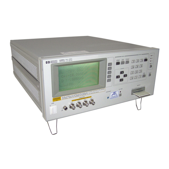
- Page 1 All manuals and user guides at all-guides.com Agilent 4285A Precision LCR Meter Getting Started Guide SERIAL NUMBERS Agilent Part No. 04285-90011 Printed in JAPAN March 2001 Fourth Edition...
- Page 2 All manuals and user guides at all-guides.com Notice...
- Page 3 All manuals and user guides at all-guides.com Manual Printing History : : : : : : : : : : : : : : : : : : : : : : : : : : : : : : : : : : : : : : : : : : : : : : : : : : : : : :...
- Page 4 All manuals and user guides at all-guides.com Safety Summary WARNINGS The Agilent Technologies assumes no liability for the customer's failure to comply with these requirements. Note Note Ground The Instrument DO NOT Operate In An Explosive Atmosphere Keep Away From Live...
- Page 5 All manuals and user guides at all-guides.com Safety Symbols Warning Caution Note...
- Page 6 All manuals and user guides at all-guides.com 4285A Precision LCR Meter Documentation 4285A Getting Started Guide 4285A OPERATION MANUAL 4285A MAINTENANCE MANUAL 4285A SERVICE MANUAL...
- Page 7 All manuals and user guides at all-guides.com Typeface Bold Conventions icons Italics lename HARDKEYS NNNNNNNNNNNNNNNNNNNNNNNNNN NNNNN Certi cation nist Warranty...
- Page 8 tness for a particular purpose. Exclusive The remedies provided herein are buyer's sole and exclusive Remedies remedies. Agilent Technologies shall not be liable for any direct, indirect, special, incidental, or consequential damages, whether based on contract, tort, or any other legal theory. Assistance...
-
Page 9: Table Of Contents
All manuals and user guides at all-guides.com Contents 1. Before You Begin 2. Getting Acquainted with the 4285A TRIGGER DC-BIAS 3. Basic Measurement Examples Contents-1... - Page 10 All manuals and user guides at all-guides.com 4. Instrument Feature Tutorial 5. What's Next? Index Contents-2...
- Page 11 All manuals and user guides at all-guides.com Figures Contents-3...
- Page 12 All manuals and user guides at all-guides.com Tables NNNNNNNNNNNNNNNNNNNNNNNNNNNNNNNN NNNNNNNNNNNNNNNNNNNNNNNNNNNNNNNN Contents-4...
-
Page 13: Before You Begin
All manuals and user guides at all-guides.com Before Y ou Begin Initial Considerations 4285A Maintenance Manual Before Y ou Begin... - Page 14 All manuals and user guides at all-guides.com Preparation for Power Requirements Line Voltage and Fuse Selection Figure 1-1. Line Voltage Selector Caution Line Voltage Selection Table 1-1. Line Voltage Selection Voltage Line Selector Voltage Fuse Selection Before Y ou Begin...
- Page 15 All manuals and user guides at all-guides.com Table 1-2. Fuse Selection Operating Fuse Fuse Voltage Rating/Type Part Number Caution Setting Up the High Current DC Biased Measurement System Equipment Required Installing the Test Fixture Before Y ou Begin...
- Page 16 All manuals and user guides at all-guides.com Interconnecting the Units Figure 1-2. Bias Current System Con guration Setting Up the Precision Q Measurement System Equipment Required Interconnecting the Units Before Y ou Begin...
- Page 17 All manuals and user guides at all-guides.com Figure 1-3. Q Measurement System Con guration Connecting 4285A, 42841A, and 42851A CONFIG SYSTEM CONFIG Equipment Required Interconnecting Cables Before Y ou Begin...
- Page 18 All manuals and user guides at all-guides.com Figure 1-4. Chaining the 42841A and the 42851A 4285A Maintenance Manual Before Y ou Begin...
-
Page 19: Getting Acquainted With The 4285A
All manuals and user guides at all-guides.com Getting Acquainted with the 4285A Front Panel Description Figure 2-1. Front Panel Overview LCD Panel and Softkey HARDKEY NNNNNNNNNNNNNNNNNNNNNNN Getting Acquainted with the 4285A... - Page 20 Display Pages DISPLAY pages ITALICS What is the Measurement Modes? CONFIG SYSTEM CONFIG CATALOG/SYSTEM Figure 2-2. MENU Keys DISPLAY FORMAT MEAS SETUP MEAS SETUP MEAS DISPLAY DISPLAY FORMAT MEAS DISPLAY BIN No. DISPLAY BIN COUNT DISPLAY Getting Acquainted with the 4285A...
- Page 21 MEAS SETUP MEAS SETUP CORRECTION LIMIT TABLE SETUP LIST SWEEP SETUP CATALOG/SYSTEM CATALOG CATALOG/SYSTEM CATALOG SYSTEM CONFIGURATION CABLE CORRECTION SELF TEST Note DISPLAY FORMAT MEAS SETUP Di erence between Field and Monitor Area CURSOR and CURSOR Keys Getting Acquainted with the 4285A...
-
Page 22: Lcl
All manuals and user guides at all-guides.com ENTRY Keys ENTER BACK SPACE ENTER BACK SPACE Figure 2-3. Entry Keys GPIB Status Indicator gpib TRIGGER Getting Acquainted with the 4285A... -
Page 23: Dc-Bias
All manuals and user guides at all-guides.com Memory Card Slot CATALOG Caution clicks DC BIAS DC-BIAS DC BIAS DC BIAS DC BIAS DC BIAS Contrast Control Knob Getting Acquainted with the 4285A... - Page 24 All manuals and user guides at all-guides.com Front Panel Operation Figure 2-4. CURSOR Keys and Field Operation Example ENTER ENTER ENTER Getting Acquainted with the 4285A...
-
Page 25: Basic Measurement Examples
All manuals and user guides at all-guides.com Basic Measurement Examples Introduction Capacitor Measurement Measurement Conditions Equipment Required Operation Procedure NNNNNNNNNNNNNNNNNNNNNNNNNNNNNNNNNNNNNNNNN SYSTEM CONFIG CATALOG/SYSTEM NNNNNNNNNNNNNNNNNNNN NNNNNNNNNNNNNNNNNNNNNNNNNNNNN CONFIG NNNNNNNNNNN NNNNNNNNNNN MEAS DISPLAY FREQ FREQ NNNNNNNNNNN NNNNNNNNNNN NNNNNNNNNNN FREQ Basic Measurement Examples... - Page 26 All manuals and user guides at all-guides.com Note NNNNNNNNNNNNNNNNNNNN NNNNNNNNNNNNNNNNNNNNNNNNNN NNNNNNNNNNNNNNNNNNNNNNNNNN NNNNNNNNNNNNNNNNNNNN NNNNNNNNNNNNNNNNNNNN NNNNNNNNNNNNNNNNNNNN FREQ NNNNNNNNNNNNNNNNNNNNNNNNNN NNNNNNNNNNNNNNNNNNNNNNNNNN NNNNNNNNNNNNNN NNNNNNNNNNNNNN Note MEAS SETUP MEAS SETUP MEAS SETUP Figure 3-1. Connecting the 16047C Basic Measurement Examples...
- Page 27 All manuals and user guides at all-guides.com NNNNNNNNNNNNNNNNNNNNNNNNNNNNNNNN CORRECTION MEAS SETUP NNNNNNNN NNNNNNNNNNN OPEN NNNNNNNNNNNNNNNNNNNNNNNNNNNNN NNNNNNNNNNNNNNNNNNNNNNNNNNNNN NNNNNNNN Figure 3-2. Connecting a Shorting Bar NNNNNNNN NNNNNNNNNNN SHORT NNNNNNNNNNNNNNNNNNNNNNNNNNNNNNNN NNNNNNNNNNNNNNNNNNNNNNNNNNNNNNNN NNNNNNNN Basic Measurement Examples...
- Page 28 All manuals and user guides at all-guides.com Figure 3-3. Connecting DUT to the 16047C DISPLAY FORMAT Figure 3-4. Measurement Results for a 220 pF Capacitor Basic Measurement Examples...
- Page 29 All manuals and user guides at all-guides.com Inductance Measurements Measurement Conditions Equipment Required Operation Procedure NNNNNNNNNNNNNNNNNNNNNNNNNNNNNNNNNNNNNNNNN SYSTEM CONFIG CATALOG/SYSTEM NNNNNNNNNNNNNNNNNNNN NNNNNNNNNNNNNNNNNNNNNNNNNNNNN CONFIG NNNNNNNNNNN NNNNNNNNNNN MEAS DISPLAY FUNC NNNNNNNNNNNNNN NNNNNNNNNNNNNN NNNNNNNNNNNNNN NNNNNNNNNNNNNNNNN NNNNNNNNNNNNNNNNNNNNNNNNNN NNNNNNNNNNNNNNNNNNNNNNNNNN NNNNNNNNNNNNNNNNNNNNNNNNNN NNNNNNNNNNNNNNNNN NNNNNNNNNNNNNNNNN FREQ NNNNNNNNNNN NNNNNNNNNNN NNNNNNNNNNN FREQ LEVEL NNNNNNNN...
- Page 30 All manuals and user guides at all-guides.com Note MEAS SETUP MEAS SETUP MEAS SETUP MEAS SETUP MEAS SETUP NNNNNNNN NNNNNNNNNNN NNNNNNNN Figure 3-5. Connecting the 16034E Basic Measurement Examples...
- Page 31 All manuals and user guides at all-guides.com Figure 3-6. 16034E Contacts in OPEN Condition NNNNNNNNNNNNNNNNNNNNNNNNNNNNNNNN CORRECTION MEAS SETUP NNNNNNNN NNNNNNNNNNN OPEN NNNNNNNNNNNNNNNNNNNNNNNNNNNNN NNNNNNNNNNNNNNNNNNNNNNNNNNNNN NNNNNNNN Basic Measurement Examples...
- Page 32 All manuals and user guides at all-guides.com Figure 3-7. Make the 16034E to SHORT Condition NNNNNNNN NNNNNNNNNNN SHORT NNNNNNNNNNNNNNNNNNNNNNNNNNNNNNNN NNNNNNNNNNNNNNNNNNNNNNNNNNNNNNNN NNNNNNNN Basic Measurement Examples...
- Page 33 All manuals and user guides at all-guides.com Figure 3-8. Connecting DUT to the 16034E DISPLAY FORMAT Figure 3-9. Measurement Results of The Ferrite-Cored Inductor Basic Measurement Examples...
- Page 34 All manuals and user guides at all-guides.com DC Voltage Biased Measurement Measurement Conditions Equipment Required Preparation Before Measurement Checking the Option Installed NNNNNNNNNNNNNNNNNNNNNNNNNNNNNNNNNNNNNNNNN CATALOG/SYSTEM DC BIAS (#001) Operation Procedure NNNNNNNNNNNNNNNNNNNNNNNNNNNNNNNNNNNNNNNNN SYSTEM CONFIG CATALOG/SYSTEM NNNNNNNNNNNNNNNNNNNN NNNNNNNNNNNNNNNNNNNNNNNNNNNNN CONFIG NNNNNNNNNNN NNNNNNNNNNN MEAS DISPLAY FREQ NNNNNNNNNNN NNNNNNNNNNN...
- Page 35 All manuals and user guides at all-guides.com NNNNNNNN NNNNNNNNNNN NNNNNNNN Figure 3-10. Connecting the 16047C NNNNNNNNNNNNNNNNNNNNNNNNNNNNNNNN CORRECTION MEAS SETUP NNNNNNNN NNNNNNNNNNN OPEN NNNNNNNNNNNNNNNNNNNNNNNNNNNNN NNNNNNNNNNNNNNNNNNNNNNNNNNNNN NNNNNNNN Basic Measurement Examples 3-11...
- Page 36 All manuals and user guides at all-guides.com Figure 3-11. Connecting A Shorting Bar NNNNNNNN NNNNNNNNNNN SHORT NNNNNNNNNNNNNNNNNNNNNNNNNNNNNNNN NNNNNNNNNNNNNNNNNNNNNNNNNNNNNNNN NNNNNNNN 3-12 Basic Measurement Examples...
- Page 37 All manuals and user guides at all-guides.com Figure 3-12. Connecting DUT MEAS FORMAT Figure 3-13. Voltage Biased (Option 001) Measurement Results Basic Measurement Examples 3-13...
- Page 38 All manuals and user guides at all-guides.com Measurements Using 1m/2m Test Leads Note Equipment Required Operation Procedure NNNNNNNNNNNNNNNNNNNNNNNNNNNNNNNNNNNNNN CABLE CATALOG/SYSTEM CORRECTION CABLE CORRECTION MENU 2 m CABLE ENTER CORRECTION 3-14 Basic Measurement Examples...
- Page 39 All manuals and user guides at all-guides.com Figure 3-14. Cable Correction Page Figure 3-15. 42102A 100 Resistor connection NNNNNNNNNNNNNNNNNNNNNNN NNNNNNNNNNNNNNNNNNNNNNN Basic Measurement Examples 3-15...
- Page 40 All manuals and user guides at all-guides.com Figure 3-16. OPEN Termination Connection Figure 3-17. OPEN Termination (Alternative) 3-16 Basic Measurement Examples...
- Page 41 All manuals and user guides at all-guides.com NNNNNNNNNNNNNN NNNNNNNNNNNNNN Figure 3-18. SHORT Termination Connection Basic Measurement Examples 3-17...
- Page 42 All manuals and user guides at all-guides.com Figure 3-19. SHORT Termination (Alternative) NNNNNNNNNNNNNNNNN NNNNNNNNNNNNNNNNN Figure 3-20. 100 Resistor Connection 3-18 Basic Measurement Examples...
- Page 43 All manuals and user guides at all-guides.com NNNNNNNNNNNNNN NNNNNNNNNNNNNN NNNNNNNNNNNNNN CABLE CORRECTION Note Basic Measurement Examples 3-19...
- Page 44 All manuals and user guides at all-guides.com DC Current Biased Measurement Measurement Conditions Equipment Required Preparation Before Measurement Checking the Option Installed NNNNNNNNNNNNNNNNNNNNNNNNNNNNNNNNNNNNNNNNN CATALOG/SYSTEM ACCESSORY I/F (#002) Con guring the High Current Biased Measurement System 3-20 Basic Measurement Examples...
- Page 45 All manuals and user guides at all-guides.com Figure 3-21. 42842C Bias Current Test Fixture Connection Basic Measurement Examples 3-21...
- Page 46 The 42842C mounted on the 42841A must be placed on a desk or bench. DO NOT stack the 42841A with the 42842C and the 4285A, DO NOT put any thing on the 42842C, and DO NOT lean on it, as shown below. Doing this may cause the instrument to tumble over.
- Page 47 All manuals and user guides at all-guides.com Figure 3-22. High Current Biased Measurement Setup Operation Procedure NNNNNNNNNNNNNNNNNNNNNNNNNNNNNNNNNNNNNNNNN SYSTEM CONFIG CATALOG/SYSTEM NNNNNNNNNNNNNNNNNNNN NNNNNNNNNNNNNNNNNNNNNNNNNNNNN CONFIG NNNNNNNNNNN NNNNNNNNNNNNNNNNNNNN MEAS DISPLAY FREQ NNNNNNNNNNN NNNNNNNNNNN NNNNNNNNNNN FREQ BIAS NNNNNNNN NNNNN NNNNNNNN NNNNNNNN NNNNN NNNNN BIAS Basic Measurement Examples 3-23...
- Page 48 All manuals and user guides at all-guides.com NNNNNNNNNNNNNNNNNNNNNNNNNNNNNNNN CORRECTION MEAS SETUP Figure 3-23. Open Condition of the 42842C NNNNNNNN NNNNNNNNNNN OPEN NNNNNNNNNNNNNNNNNNNNNNNNNNNNN NNNNNNNNNNNNNNNNNNNNNNNNNNNNN NNNNNNNN 3-24 Basic Measurement Examples...
- Page 49 All manuals and user guides at all-guides.com Figure 3-24. Connecting the Furnished Shorting Bar NNNNNNNN NNNNNNNNNNN SHORT NNNNNNNNNNNNNNNNNNNNNNNNNNNNNNNN NNNNNNNNNNNNNNNNNNNNNNNNNNNNNNNN NNNNNNNN DC BIAS DISP FORMAT Basic Measurement Examples 3-25...
- Page 50 All manuals and user guides at all-guides.com Figure 3-25. Ferrite-Cored Inductor Measurement Results DC BIAS 3-26 Basic Measurement Examples...
- Page 51 All manuals and user guides at all-guides.com Precision Q Measurement Measurement Conditions Equipment Required Preparation Before Measurement Checking the Option Installed NNNNNNNNNNNNNNNNNNNNNNNNNNNNNNNNNNNNNNNNN CATALOG/SYSTEM ACCESSORY I/F (#002) Con gure the Precision Q measurement System Basic Measurement Examples 3-27...
- Page 52 All manuals and user guides at all-guides.com Figure 3-26. Precision Q Measurement Setup Operation Procedure NNNNNNNNNNNNNNNNNNNNNNNNNNNNNNNNNNNNNNNNN SYSTEM CONFIG CATALOG/SYSTEM NNNNNNNNNNNNNNNNNNNN NNNNNNNNNNNNNNNNNNNNNNNNNNNNN CONFIG NNNNNNNNNNN NNNNNNNNNNNNNNNNNNNNNNNNNNNNN MEAS DISPLAY FREQ NNNNNNNNNNN NNNNNNNNNNN NNNNNNNNNNN FREQ 3-28 Basic Measurement Examples...
- Page 53 All manuals and user guides at all-guides.com Figure 3-27. Connecting a Shorting Bar NNNNNNNNNNNNNNNNNNNNNNNNNNNNNNNN Q CORRECTION MEAS SETUP NNNNNNNN NNNNNNNNNNN SHORT NNNNNNNNNNNNNNNNNNNNNNNNNNNNNNNN NNNNNNNNNNNNNNNNNNNNNNNNNNNNNNNN NNNNNNNN HIGH Note Q MEAS SETUP 42851A Operation Manual Basic Measurement Examples 3-29...
- Page 54 All manuals and user guides at all-guides.com Figure 3-28. Connecting the SMD Test Fixture Figure 3-29. Connecting DUT to the SMD Test Fixture DISP FORMAT TRIGGER HIGH 3-30 Basic Measurement Examples...
- Page 55 All manuals and user guides at all-guides.com Figure 3-30. Inductor Precise Q Measurement Results Basic Measurement Examples 3-31...
- Page 56 All manuals and user guides at all-guides.com...
- Page 57 All manuals and user guides at all-guides.com Instrument Feature Tutorial Memory Function System Memory CORRECTION SYSTEM CONFIG Instrument Feature T utorial...
- Page 58 All manuals and user guides at all-guides.com Internal Non-Volatile Memory/External Memory Card CATALOG MEAS SETUP LIMIT TABLE BIN COUNT DISPLAY LIST SWEEP SETUP Note DC BIAS SYS MENU NNNNNNNNNNNNNNNNN ENTER SYS MENU NNNNNNNNNNNNNN ENTER Instrument Feature T utorial...
- Page 59 All manuals and user guides at all-guides.com Automatic Level Control Function ALC Theory of Operation Figure 4-1. Feedback Control Circuit Instrument Feature T utorial...
- Page 60 All manuals and user guides at all-guides.com ALC Measurement Time ALC Voltage/Current Setting Range Note Operation Procedure of the ALC Function MEAS SETUP MEAS SETUP NNNNNNNN NNNNNNNNNNN NNNNNNNN NNNNNNNNNNN Instrument Feature T utorial...
- Page 61 All manuals and user guides at all-guides.com List Sweep Function Structure of LIST SWEEP function LIST SWEEP DISPLAY DISPLAY FORMAT LIST SWEEP SETUP MEAS SETUP Figure 4-2. Structure of LIST SWEEP Function LIST SWEEP DISPLAY page LIST SWEEP SETUP page MODE Instrument Feature T utorial...
- Page 62 All manuals and user guides at all-guides.com FREQ[Hz] LEVEL[V] LEVEL[A] BIAS[V] BIAS[A] LOW HIGH MEAS SETUP LIST SWEEP Measurement Procedure FUNCTION SWEEP MODE SWEEP PARAMETER SWEEP POINTS LIMIT PARAMETER Other Settings NNNNNNNNNNNNNNNNNNNNNNNNNNNNNNNNNNNNNNNNN SYSTEM CONFIG CATALOG/SYSTEM ACCESSORY CONTROL INTERFACE NNNNNNNNNNNNNNNNNNNN NNNNNNNNNNNNNNNNNNNNNNNNNNNNN NNNNNNNNNNN NNNNNNNNNNN MEAS SETUP...
- Page 63 All manuals and user guides at all-guides.com Figure 4-3. List Sweep Modes FREQ [Hz] LEVEL [V] LEVEL [A] BIAS [V] BIAS [A] NNNNNNNNNNNNNNNNNNNNNNNNNNNNN NNNNNNNNNNN NNNNNNNNNNNNNNNNNNNNNNNNNNNNNNNNNNNNNN NNNNNNNNNNNNNNNNNNNNNNNNNNNNNNNNNNNNNN NNNNNNNNNNN NNNNNNNNNNN NNNNNNNNNNN NNNNNNNNNNN Instrument Feature T utorial...
- Page 64 All manuals and user guides at all-guides.com NNNNNNNNNNN NNNNNNNNNNN NNNNNNNNNNN NNNNNNNNNNN NNNNNNNNNNN NNNNNNNNNNN NNNNNNNNNNN NNNNNNNNNNN NNNNNNNNNNN NNNNNNNNNNN NNNNNNNNNNN NNNNNNNNNNN NNNNNNNNNNN NNNNNNNNNNN NNNNNNNNNNN NNNNNNNNNNN NNNNNNNNNNNNNNNNNNNNNNNNNNNNNNNN DISPLAY FORMAT Instrument Feature T utorial...
- Page 65 All manuals and user guides at all-guides.com Print Function CATALOG/SYSTEM NNNNNNNNNNNNNNNNNNNNNNNNNNNNNNNNNNNNNNNNN SYSTEM CONFIG NNNNNNNN TALK ONLY TALK ONLY Print Mode NNNNNNNNNNNNNNNNNNNNNNNNNNNNNNNN NNNNNNNNNNNNNNNNNNNNNNNNNNNNNNNN NNNNNNNNNNNNNNNNNNNNNNNNNNNNNNNN NNNNNNNNNNNNNNNNNNNNNNNNNNNNNNNN NNNNNNNNNNNNNNNNNNNNNNNNNNNNNNNN NNNNNNNNNNNNNNNNNNNNNNNNNNNNNNNN NNNNNNNNNNNNNNNNNNNNNNNNNNNNNNNN NNNNNNNNNNNNNNNNNNNNNNNNNNNNNNNN Table 4-1. Availability NNNNNNNNNNNNNNNNNNNNNNNNNNNNNNNNNNN NNNNNNNNNNNNNNNNNNNNNNNNNNNNNNNNNNN Page Name MEAS DISPLAY BIN No. DISPLAY BIN COUNT DISPLAY LIST SWEEP DISPLAY MEAS SETUP...
- Page 66 All manuals and user guides at all-guides.com Printer Requirements Printer Troubleshooting Appendix B 4285A operation manual (Agilent part number 04285-90000) Note 4-10 Instrument Feature T utorial...
- Page 67 All manuals and user guides at all-guides.com What's Next? 4285A OPERATION MANUAL 42851A OPERATION MANUAL 42841A OPERATION MANUAL 4285A OPERATION MANUAL 42841A OPERATION MANUAL 4285A OPERATION MANUAL What's Next?
- Page 68 All manuals and user guides at all-guides.com...