
Subscribe to Our Youtube Channel
Related Manuals for Spectracom SecureSync

Summary of Contents for Spectracom SecureSync
- Page 1 ® SecureSync Time and Frequency Synchronization System User Reference Guide Document Part No.: 1200-5000-0050 Revision: 18 Date: May12, 2015 www.spectracomcorp.com...
- Page 3 Spectracom reserves the right to make changes to the product described in this document at any time and without notice. Any software that may be provided with the product described in this document is furnished under a license agreement or nondisclosure agreement.
- Page 4 88/89, DA-35/36, GPS/GNSS Simulators Warranty Exceptions Country Variances This warranty shall not apply if the product All Spectracom products sold in India have is used contrary to the instructions in its a one year warranty. manual or is otherwise subjected to mis-...
- Page 5 Warranty Procedure howsoever caused. In no event shall Spectracom highly recommends that Spectracom be liable for any direct, prior to returning equipment for ser- indirect, special or consequential dam- vice work, our technical support depart-...
- Page 6 SecureSync User Reference Guide...
-
Page 7: Table Of Contents
1.9 Regulatory Compliance CHAPTER 2 INSTALLATION 2.1 Installation and Setup Summary 2.2 Main Installation Steps 2.3 Unpacking and Inventory 2.4 Required Tools and Parts for Installation 2.5 SAFETY 2.5.1 Safety: Symbols Used • TABLE OF CONTENTS SecureSync User Reference Guide... - Page 8 2.12.2 Network Configuration via Front Panel 2.12.3 Network Configuration via Serial Port 2.13 Typical Post-Installation Configurations 2.13.1 Displaying Local Time 2.13.2 Synchronizing Network PCs 2.14 Product Registration CHAPTER 3 CONFIGURATION 3.1 Product Configuration via the Web UI • TABLE OF CONTENTS SecureSync User Reference Guide...
- Page 9 3.4.4 NTP Timing System: Reference Selection and Preference 3.4.5 NTP Keys 3.4.6 NTP over Anycast 3.4.7 NTP Expert Mode 3.4.8 Spectracom Technical Support for NTP 3.4.9 NTP Servers: Adding, Configuring, Deleting 3.4.10 NTP Peers: Adding, Configuring, Deleting 3.4.11 Configuring NTP Symmetric Keys (MD5 Authentication) 3.4.12 Configuring NTP Access Restrictions...
- Page 10 3.9.1 Issuing HALT Command via the Web UI 3.9.2 Issuing HALT Command via Keypad/SerialPort/Telnet/SSS 3.10 Rebooting the System 3.10.1 Rebooting via LCD/Keypad, Serial Port, Telnet, SSH, SNMP 3.11 If a Secure Unit Becomes Inaccessible CHAPTER 4 OPERATION VIII • TABLE OF CONTENTS SecureSync User Reference Guide...
- Page 11 4.11.1 Types of Logs 4.11.2 Local and Remote Logs 4.11.3 The Logs Screen 4.11.4 Displaying Individual Logs 4.11.5 Saving and Downloading Logs 4.11.6 Configuring Logs 4.11.7 Setting up a Remote Log Server • TABLE OF CONTENTS SecureSync User Reference Guide...
- Page 12 5.2.5 Programmable Frequency Out [1204-13, -2F, -30] 5.2.6 Programmable Square Wave Out [1204-17] 5.2.7 Simulcast (CTCSS/Data Clock) [1204-14] 5.3 Telecom Option Cards 5.3.1 T1/E1 Out [1204-09, -0A] 5.4 Time Code Option Cards 5.4.1 IRIG Out [1204-15, -1E, -22] • TABLE OF CONTENTS SecureSync User Reference Guide...
- Page 13 5.7.11 PROCEDURE 8: Gb ETH Card Installation, Slot1 Empty 5.7.12 PROCEDURE 9: Gb ETH Card Installation, Slot1 Occupied 5.7.13 PROCEDURE 10: Alarm Relay Card, Cable Installation 5.7.14 PROCEDURE 11: Verifying Successful Installation 5.7.15 PROCEDURE 12: Restoring Reference Priority Configuration (optional) • TABLE OF CONTENTS SecureSync User Reference Guide...
- Page 14 8.1.2 NMEA RMC Message 8.1.3 NMEA ZDA Message 8.1.4 Spectracom Format 0 8.1.5 Spectracom Format 1 8.1.6 Spectracom Format 1S 8.1.7 Spectracom Format 2 8.1.8 Spectracom Format 3 8.1.9 Spectracom Format 4 • TABLE OF CONTENTS SecureSync User Reference Guide...
- Page 15 8.3 Technical Support 8.3.1 Regional Contact 8.4 Return Shipments 8.5 License Notices 8.5.1 NTPv4.2.6p5 8.5.2 OpenSSH 8.5.3 OpenSSL 8.6 List of Tables 8.7 List of Images 8.8 Document Revision History INDEX • TABLE OF CONTENTS XIII SecureSync User Reference Guide...
- Page 16 BLANK PAGE. • TABLE OF CONTENTS SecureSync User Reference Guide...
-
Page 17: Introduction & Overview
Introduction & Overview The Chapter presents an overview of the SecureSync Time and Fre- quency Synchronization System, its capabilities, main technical fea- tures and functions. T he following topics are included in this Chapter: 1.1 Getting Started 1.2 Introduction 1.3 Inputs and Outputs 1.4 General Information about GPS and GNSS... -
Page 18: Getting Started
1.1 Getting Started Getting Started Welcome to this User Reference Guide for your SecureSync unit. Whether you read this online, on paper, or in a pdf document, we sincerely hope you'll quickly find your way around. Depending on what your objective is today, here are our recommendations on what to do next:... -
Page 19: Inputs And Outputs
An important advantage of SecureSync is its unique rugged and flexible modular chassis that can be configured for your specific needs. Built-in time and frequency functions are extended with up to six input/output modules. -
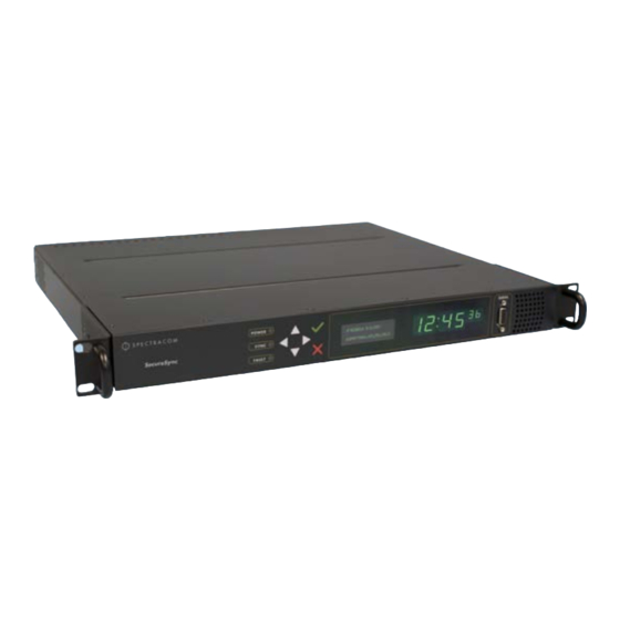
Page 20: Front Panel
Front Panel The front panel of the SecureSync unit consists of three separate illuminated status LEDs, a front panel control keypad, an LED time display, an LCD information display, an RS-232 serial inter- face, and a temperature controlled cooling fan. - Page 21 FAULT : Two-color, three-state LED, indicating possible equipment fault. At power up, the unit automatically performs a brief LED test run during which all three LEDs are temporarily lit. The following table provides an overview of the LED status indications: CHAPTER • SecureSync User Reference Guide Rev. 18...
-
Page 22: Rear Panel
"Minor and Major Alarms" on page 448 ive (Refer to troubleshooting this condition). Table 1-1: SecureSync front panel status indicators Rear Panel The SecureSync rear panel accommodates the connectors for all input and output references. CHAPTER • SecureSync User Reference Guide Rev. 18... -
Page 23: Spectracom Format
However, not all cards can be installed in all slots. Your local Spectracom Sales Office will gladly assist you with the optimal option cards selection for your application. -
Page 24: Specifications
GLONASS L1 transmissions centered at 1602.0 MHz Satellites tracked : Up to 32 simultaneously Acquisition time : Typically <4 minutes from cold start Antenna requirements : Active antenna module, +5V, powered by SecureSync, 16 dB gain min- imum Antenna connector : Type N, female 1.8.2... -
Page 25: 10/100 Ethernet Port
10 MHz Output Signal : 10 MHz sine wave Signal level :+13 dBm +/- 2 dB into 50 Ω Harmonics : -40 dBc minimum Spurious : –70 dBc minimum Connector : BNC female CHAPTER • SecureSync User Reference Guide Rev. 18... -
Page 26: Input Power
Rubidium (Rb) oscillator installed — 50 W normal (80 W start-up) Low-Phase Noise (LPN) Rubidium (Rb) oscillator installed — 52 W normal (85 W start-up) 1.8.8 Fuses Type : T 2A L 250 V Model : CHAPTER • SecureSync User Reference Guide Rev. 18... -
Page 27: Mechanical And Environmental Specifications
1.8 Specifications Spectracom recommends: LITTELFUSE 0213002.MXP [Spectracom part number: F010R-0002-000 E FUSE,2A,SB,IEC SURGE,GLASS] Number : 2 (two) per unit SecureSync label on rear panel of unit: " AC POWER/F 2A T 250V (2) " LEGEND: F = Fuse 2A = Current Rating: 2 Ampères... -
Page 28: Regulatory Compliance
Safety EN 60950 -1:2006/A11:2009: Safety of Information Technology Equipment, including Electrical Business Equipment This product has been tested and meets the requirements specified in: CHAPTER • SecureSync User Reference Guide Rev. 18... - Page 29 ICES-003 and AS/NZS CISPR 22: This Class (A) digital apparatus complies with Canadian ICES-003, Issue 4. This Class (A) digital apparatus complies with AS/NZS CISPR 22 for radiated and con- ducted Emissions. CHAPTER • SecureSync User Reference Guide Rev. 18...
- Page 30 1.9 Regulatory Compliance BLANK PAGE. CHAPTER • SecureSync User Reference Guide Rev. 18...
-
Page 31: Installation
INSTALLATION This Chapter guides you through the preparation of the hardware, the installation of the SecureSync Time and Frequency Synchronization System, its hardware interfaces, and setup tasks required to be per- formed before configuring the product. T he following topics are included in this Chapter: 2.1 Installation and Setup Summary... -
Page 32: Installation And Setup Summary
2.13.2 Synchronizing Network PCs 2.14 Product Registration Installation and Setup Summary This section provides an outline of the SecureSync installation process. The exact installation pro- cedure of your unit depends on several factors: The power source(s) your SecureSync is configured for. -
Page 33: Unpacking And Inventory
…or via serial port, using a PC with a CLI: "Network Configuration via Serial Port" on page 34 iii. …or via Ethernet, using a PC with a Web browser, and the SecureSync Web UI: "DHCP Network Configuration" on page 30. Register your product: "Product Registration" on page 36. -
Page 34: Required Tools And Parts For Installation
Phillips screwdriver to install the unit’s rack-mount ears. Screwdriver to mount the unit in a standard 19-inch rack. Ethernet cables (see "Ethernet Connection" on page 26) For DC power supply (if applicable), Spectracom recommends an external ON/OFF switch. SAFETY 2.5.1 Safety: Symbols Used... -
Page 35: Safety: Before You Begin Installation
Before you begin installing and configuring your SecureSync unit, carefully read the following important safety statements. Always ensure that you adhere to any and all applicable safety warn- ings, guidelines, or precautions during the installation, operation, and maintenance of your product. - Page 36 AC or DC system. The AC or DC system shall not be earthed elsewhere. Switches or other disconnection devices shall not be in the earthed circuit conductor between the AC and DC source and the point of the connection of the earthing CHAPTER • SecureSync User Reference Guide Rev. 18...
-
Page 37: Safety: User Responsibilities
Do not modify the equipment. Use only spare parts authorized by Spectracom. Always follow the instructions set out in this User Reference Guide, or in other Spectracom documentation for this product. Observe generally applicable legal and other local mandatory regulations. -
Page 38: Rack Mounting
SecureSync unit. If the SecureSync unit is to be installed in a closed rack, or a rack with large amounts of other equipment, a rack cooling fan or fans should be part of the rack mount installation. -
Page 39: Desktop Operation
2.7.1 Input Power Selection As long as the AC input power is present, and SecureSync is equipped with the DC redundancy option, it will utilize the AC power source over DC power. If AC and DC power are both applied, AC power is used. -
Page 40: Using Ac Input Power
Using AC Input Power Connect the AC power cord supplied in the SecureSync ancillary kit to the AC input on the rear panel and the AC power source outlet. The AC input is fuse-protected with two fuses located in the AC power entry module (line and neutral inputs are fused). -
Page 41: Connecting Reference Input(S) And Network Interface(S)
A DC power connector to attach DC power to SecureSync is included in the ancillary kit provided with the equipment. A cable of 6 feet or less, using 16AWG wire, with adequate insulation for the DC voltage source should be used with this connector. -
Page 42: Connecting Gnss Input
Connecting GNSS Input Typical installations include GNSS as an external reference input. If the GNSS receiver is not installed or if the GNSS will not be used as a SecureSync reference, disregard the steps to install the GNSS antenna and associated cabling. -
Page 43: Powering Up The Unit
When connecting to a hub, router, or network computer, use a straight-through wired, shielded CAT 5, Cat 5E or CAT 6 cable with RJ-45 connectors. Connect one end to the Ethernet port on the SecureSync rear panel, and the opposite end of the cable to a network hub or switch. -
Page 44: Using The Keypad And Information Display
2.10 Using the Keypad and Information Display To simplify operation and to allow local access to SecureSync, a keypad and LCD information dis- play are provided on the front panel of the unit. Among other things, the keypad and information display can be used to carry out basic network configuration tasks, such as en-/disabling DHCP, or entering an IP address and subnet mask;... -
Page 45: Navigating The Information Display
(or, it can even be configured to remain blank, if desired). The figure "Keypad menu tree" below illustrates Menu Tree navigation. Figure 2-3: Keypad menu tree CHAPTER • SecureSync User Reference Guide Rev. 18... -
Page 46: Unlocking The Front Panel Keypad
SecureSync's hostname instead of IP address), Spectracom recommends to disable DHCP for SecureSync, and change the IP address to a static address. Failure to do this will result in a loss of time synchronization, should the DHCP server assign a new IP address to SecureSync. -
Page 47: Replacing A Dynamic With A Static Ip Address
SecureSync's serial port, the most convenient way is using the SecureSync Web user interface ("Web UI"): The dynamic IP address assigned to your SecureSync unit by DHCP will allow you to readily access the Web UI, in order to carry out the desired changes. -
Page 48: Network Configuration Without Dhcp
"Configuring Network Ports" on page 48. For subnet mask values, see table "Subnet mask values" on page 36. Enter the static IP address you assigned to your SecureSync unit, and again log into the Web UI in order to continue with the configuration; see: "Product Configuration via the Web UI"... -
Page 49: Network Configuration Via Front Panel
Before continuing, obtain the following network information from your network administrator: Available static IP address This is the unique address assigned to the SecureSync unit by the network admin- istrator. Make sure the chosen address is outside of the DHCP range of your DHCP server. -
Page 50: Network Configuration Via Serial Port
Next to the keypad and 4-line information display, the front panel also contains a DB9 serial port that can be used to communicate with SecureSync. The serial port connector is a standard DB9 female connector. Communication with the serial port can be performed using a terminal emulator program (such as HyperTerminal or Procomm) using a pinned straight-thru standard DB9M to DB9F serial cable. - Page 51 2.12 Network Configuration Without DHCP Connect a serial cable to a PC running HyperTerminal, and to your SecureSync. Login to SecureSync with a user account that has “admin” group rights, such as the default account (the default password for spadmin...
-
Page 52: Typical Post-Installation Configurations
"Editing the System Time" on page 169, and "Front Panel Configuration" on page 178. 2.13.2 Synchronizing Network PCs Frequently, network PCs have to be synchronized to SecureSync via the Ethernet port, using NTP (Network Time Protocol). A detailed description on how to synchronize Windows PCs can be Spec-... - Page 53 2.14 Product Registration Upon initial start of the SecureSync Web UI (see "Opening the Web UI" on page 30), you will be prompted to register your new product. It is also possible to register at a later time via the HELP Spectracom website...
- Page 54 2.14 Product Registration BLANK PAGE. CHAPTER • SecureSync User Reference Guide Rev. 18...
-
Page 55: Configuration
CONFIGURATION In this chapter you will find information on how to integrate the SecureSync Time and Frequency Synchronization System into your existing infrastructure by configuring it in accordance with the require- ments of your application. T he following topics are included in this Chapter: 3.1 Product Configuration via the Web UI... - Page 56 3.9.1 Issuing HALT Command via the Web UI 3.9.2 Issuing HALT Command via Keypad/SerialPort/Telnet/SSS 3.10 Rebooting the System 3.10.1 Rebooting via LCD/Keypad, Serial Port, Telnet, SSH, SNMP 3.11 If a Secure Unit Becomes Inaccessible CHAPTER • SecureSync User Reference Guide Rev. 18...
-
Page 57: Product Configuration Via The Web Ui
3.1 Product Configuration via the Web UI Product Configuration via the Web UI Once SecureSync has been setup and connected to your network, you may configure it, change its operating settings, check status, and generate reports, using the Web User Interface (through- out this document referred to as “Web UI”). - Page 58 HELP/MONITORING : Opens a drop-down menu for access to system help and inform- ation on how to contact Spectracom for further help. (Once you have applied the optional TimeKeeper license, this button will open the TimeKeeper Monitoring menu. See also "Status Monitoring with TimeKeeper"...
-
Page 59: Accessing Setup Pages Via The Management Menu
SNMP Trap and/or email. Time Management —Manage the Local Clock, UTC Offset, DST Definition and Leap Second information. Front Panel —Configure the appearance of the SecureSync front panel display and keypad. Log Configuration —Manage the system logs. Disciplining —Manage oscillator disciplining. -
Page 60: Default And Recommended Configurations
Disabled (use SFTP or SCP) Web UI Table 3-1: Default and recommended configurations *Spectracom recommends that secure clients use only SNMPv3 with authentication for secure installations. NETWORK Setup Pages All of the network setup pages can be accessed from the MANAGEMENT drop-down menu, under NETWORK . -
Page 61: General Setup
Hostname —This is the server’s identity on the network or IP address. The default is tracom Default Gateway IPv6 —The gateway (default router) address is needed if communication to the SecureSync is made outside of the local network. By default, the gateway is dis- abled. In the format “ ####.####.####.####.####.####.####.#### ,”... -
Page 62: Configuring Ethernet
Configuring Ethernet 3.3.2.1 The Network Management Screen In order to monitor Ethernet status, and manage Ethernet configuration settings on SecureSync: Navigate to the Network Management screen through MANAGEMENT/NETWORK . The Network Management screen will display. It is divided into three panels: CHAPTER •... - Page 63 Login Banner : Allows the administrator to configure a custom banner message to be dis- played on the SecureSync Web UI login page (NOTE: There is a 2000 character size limit). SSH : This button takes you to the SSH Setup window. For details on setting up SSH, see "Configuring SSH"...
- Page 64 Navigate to the Network Management screen through the MANAGEMENT/NETWORK drop-down menu. The Ports panel will show the Ethernet ports you have available and their connection status. Locate the port you want to configure and select the GEAR button. CHAPTER • SecureSync User Reference Guide Rev. 18...
- Page 65 IPv4 Gateway —The gateway (default router) address is needed if com- munication to the SecureSync is made outside of the local network. By default, the gateway is disabled. DNS Primary —This is the primary DNS address to be used for this port. This is set automatically if DHCP is enabled.
- Page 66 Unless you are using DNS in conjunction with DHCP (with the client con- figured using SecureSync’s hostname instead of IP address), DHCP should be dis- abled and the IP address should be changed to a static address once SecureSync is properly configured.
- Page 67 The Ports panel will show the Ethernet ports you have available and their connection status. In the Ports panel, locate the port you want to configure and click the INFO button. The Eth- ernet Port Status window will display: The following configurations can be viewed: CHAPTER • SecureSync User Reference Guide Rev. 18...
- Page 68 3.3 NETWORK Setup Pages The port number (the built in SecureSync is designated eth0). The status will be one of: CONNECTED (showing the connection speed) in green. DISABLED in orange. CABLE UNPLUGGED (the port is enabled but there is not cable attached) in orange.
- Page 69 The Ports panel will show the Ethernet ports you have available and their connection status. In the Ports panel, click the TABLE icon in the upper right-hand corner. The Static Routes window will display: CHAPTER • SecureSync User Reference Guide Rev. 18...
- Page 70 The Static Routes window will display: NOTE – The eth0 port is the default port for static routing on SecureSync. If a port is not given its own static route, all packets from that port will be sent through the default.
- Page 71 The Ports panel will show the Ethernet ports you have available and their connection status. In the Ports panel, locate the port you want to configure, and click the TABLE button. The Static Routes window will display. CHAPTER • SecureSync User Reference Guide Rev. 18...
- Page 72 The Ports panel will show the Ethernet ports you have available and their connection status. In the Ports panel, locate the port you want to configure, and click the TABLE button. The Static Routes window will display: CHAPTER • SecureSync User Reference Guide Rev. 18...
- Page 73 3.3.2.9 Configuring Network Access Rules To configure access restrictions from assigned networks or nodes: Navigate to the Network Management screen through the MANAGEMENT/NETWORK dropdown menu. In the Actions panel, click on Access Control. CHAPTER • SecureSync User Reference Guide Rev. 18...
- Page 74 See "Network Configuration Without DHCP" on page 32 for information on subnet masks. IPv6— , representing 2001:db8::/48 2001:db8:0:0:0:0:0:0 2001:db8:0:ffff:ffff:ffff:ffff:ffff. Click the Add button in the Action column. The established rule appears in the Network Access Rules window. CHAPTER • SecureSync User Reference Guide Rev. 18...
- Page 75 Locate the rule you wish to delete and click the Delete button corresponding to that rule. 3.3.2.11 Configuring the Login Banner To configure a custom banner message to be displayed on the SecureSync login page: Navigate to the Network Management screen through the MANAGEMENT/NETWORK dropdown menu.
- Page 76 Log out using the LOG OUT button at the top of the Web UI. Click the LOG IN button at the top of the Web UI. The banner will appear above the USERNAME and PASSWORD fields: CHAPTER • SecureSync User Reference Guide Rev. 18...
- Page 77 On the Network Access Banner screen, select on the Enable Web Interface Banner but- ton at the bottom of the screen. The Web UI text box will display. Enter the text you wish to appear on the Web UI login screen. CHAPTER • SecureSync User Reference Guide Rev. 18...
- Page 78 Log out using the LOG OUT button at the top of the Web UI. Click the LOG IN button at the top of the Web UI. The banner will appear above the USERNAME and PASSWORD fields. CHAPTER • SecureSync User Reference Guide Rev. 18...
-
Page 79: Network Services: En-/Disabling
Classic UI : This toggle switch allows the SecureSync Classic Interface (as used in SecureSync Web UI Version 4.x and older) to be enabled or disabled. [Default : ENABLED] To disable, select the OFF position, and refresh the browser window (the refresh may take a moment). -
Page 80: Configuring Https
3.3.4.1 Accessing the HTTPS Setup Screen To access the HTTPS Setup screen: Navigate to MANAGEMENT > NETWORK > HTTPS Setup , or, in the NETWORK > Actions panel, select HTTPS. The HTTPS Setup window will appear: CHAPTER • SecureSync User Reference Guide Rev. 18... - Page 81 Upload X509 Certificate —The certificate returned by the Certificate Authority is uploaded under this tab. Edit X509 PEM Certificate —The certificate used by the SecureSync is stored here. NOTE – You can exit the HTTPS Setup window by clicking on the X at the top right of the window or by clicking anywhere outside the window.
- Page 82 3.3.4.2 Using HTTPS HTTPS provides secure/encrypted, web-based management and configuration of SecureSync from a PC. An SSL certificate is required to be in SecureSync in order to make this secure HTTPS connection. SecureSync uses OpenSSL library with a simple GUI interface to create certificate requests and self-signed certificates.
- Page 83 Fill in the available fields: Create Self-Signed Certificate —Check this box if the Certificate you are creating is a self- signed certificate. Signature Algorithm —Choose the algorithm to be used from: SHA1 CHAPTER • SecureSync User Reference Guide Rev. 18...
- Page 84 If necessary, consult your web browser vendor’s documentation and Certificate Authority to see which key bit lengths and signature algorithms your web browser supports. Spectracom recommends that when completing the Common Name field, the user provide a static IP address, because DHCP-generated IP addresses can change. If the hostname or IP address changes, the X.509 certificate must be regenerated.
- Page 85 Authority. NOTE – It may take several minutes for the SecureSync to create the certificate request and the private key. The larger the key, the longer amount of time is required. If a system is rebooted during this time, the certificate will not be created.
- Page 86 NOTE – If you wish to create a different or additional Certificate Request, you may fill out a new form under the Certificate Request Parameters tab, and the SecureSync will automatically generate the new Certificate Request. CHAPTER • SecureSync User Reference Guide Rev. 18...
- Page 87 Until this certificate is received, the user’s self-signed certificate may be used (see "Creating a Self-Signed Certificate" on the previous page). When the SecureSync Web UI is accessed from a Windows computer while the self-signed cer- tificate is being used, the user’s web browser will present a popup window. The certificate can be viewed by the user and installed through this pop up window.
- Page 88 However, changes should not be made to a certificate once it is imported. Instead, a new certificate should be requested. An invalid certificate may result in denial of access to the SecureSync through the Web UI. If this occurs, see "If a Secure Unit Becomes Inaccessible" on page 225.
- Page 89 However, changes should not be made to a certificate once it is imported. Instead, a new certificate should be requested. An invalid certificate may result in denial of access to the SecureSync through the Web UI. If this occurs, see "If a Secure Unit Becomes Inaccessible" on page 225.
-
Page 90: Configuring Ssh
However, changes should not be made to a certificate once it is imported. Instead, a new certificate should be requested. An invalid certificate may result in denial of access to the SecureSync through the Web UI. If this occurs, see "If a Secure Unit Becomes Inaccessible" on page 225. - Page 91 3.3.5.2 Using SSH The SSH tools supported by SecureSync are: SSH —Secure Shell SCP —Secure Copy SFTP —Secure File Transfer Protocol SecureSync implements the server components of SSH, SCP, and SFTP. www.openssh.org For more information on OpenSSH, please refer to CHAPTER •...
- Page 92 IP address. Users can be authenticated either by using their account passwords or by using a Public Private Key Pair. Users keep their private key secret within their workstations or network user accounts and provide the SecureSync a copy of their public key. The modes of authentication supported include:...
- Page 93 768, 1024, and 2048. Large key sizes of up to 4096 are supported, but may take 10 minutes or more to generate. DSA keys size support is limited to 1024 bits. Click the Submit button at the bottom of the screen. The new values will be saved. CHAPTER • SecureSync User Reference Guide Rev. 18...
- Page 94 If you switch between tabs with the SSH Setup window, the information you have entered will be retained until you either leave the SSH Setup window or click the Submit button. CHAPTER • SecureSync User Reference Guide Rev. 18...
- Page 95 The Host keys are generated in the background. Creating RSA and DSA keys, each with 1024 bits length, typically takes about 30 seconds. Keys are created in the order of RSA, DSA, ECDSA. SecureSync will generate all 3 host keys, the RSA key, the DSA key and the ECDSA key.
- Page 96 Load a public key into SecureSync. This public key must match the private key found in the users account and be accessible to the SSH, SCP, or SFTP client program. The user must then enter the Passphrase after authentication of the keys to provide the second factor for 2-factor authentication.
- Page 97 The following command lines for OpenSSH SSH client tool are given as examples of how to create an SSH session. Creating an SSH session with Password Authentication for the admin account ssh spadmin@10.10.200.5 spadmin@10.10.200.5's password: admin123 CHAPTER • SecureSync User Reference Guide Rev. 18...
- Page 98 Creating an SSH session using Public Key with Passphrase Authentication for the admin account The user must first provide the secure Spectracom product a RSA public key found typically in the OpenSSH id_rsa.pub file. The user may then attempt to create an SSH session.
-
Page 99: System Time Message
The System Time Message is a feature used for special applications that require a once- per- second time message to be sent out by SecureSync via multicast. This time message will be trans- mitted before every 1PPS signal, and can be used to evaluate accuracy and jitter. - Page 100 This message contains the time when the next 1 PPS discrete will occur. It is sent once per second prior to the 1 PPS discrete. Word Byte 3 Byte 2 Byte 1 Byte 0 Msg ID Msg Size Seconds nSec Table 3-2: System Time Message Format CHAPTER • SecureSync User Reference Guide Rev. 18...
-
Page 101: Configuring Snmp And Notifications
(NMS). The agent is also responsible for controlling the database of control variables defined in the Management Information Base (MIB). SecureSync’s SNMP functionality supports SNMP versions V1, V2c and V3 (with SNMP Version 3 being a secure SNMP protocol). - Page 102 SNMP traps can be sent to over the network. This allows for SNMP Man- agers in different geographical areas to receive the same SNMP traps and Managers in other areas also receive. Clicking the PLUS icon in the top-right corner opens the CHAPTER • SecureSync User Reference Guide Rev. 18...
- Page 103 3.3.7.2 Configuring SNMP V1/V2 Communities Creating Communities Navigate to the MANAGEMENT/NETWORK/SNMP Setup screen. In the SNMP V1/V2 panel click the PLUS icon in the top-right corner. The SNMP V1/V2c Settings for Access window will display. CHAPTER • SecureSync User Reference Guide Rev. 18...
- Page 104 The choices offered below will change in context with the choice made in the IP Ver- sion field. If no value is entered in the IPv4 and/or IPv6 field, SecureSync uses the system default address. SNMP Community names should be between 4 and 32 characters in length.
- Page 105 SNMP User Names and passwords are independent of users that are configured on the Tools/Users page. User names are arbitrary. SNMP User Names should be between 1 and 31 characters in length. CHAPTER • SecureSync User Reference Guide Rev. 18...
- Page 106 3.3 NETWORK Setup Pages The User Name must be the same on SecureSync and on the management station. The Auth Type field provides a choice between MD5 and SHA. The Auth Password must be between 8 and 32 characters in length.
- Page 107 The Auth Password must be between 8 and 32 characters in length. The Priv Type field provides a choice between AES and DES. The Priv Passphrase must be between 8 and 32 characters in length. CHAPTER • SecureSync User Reference Guide Rev. 18...
- Page 108 . A varbind provides a current SecureSync data object that is related to the specific trap that was sent. For example, when a Hol- dover trap is sent because SecureSync either entered or exited the Holdover mode, the trap var- bind will indicate that SecureSync is either currently in Holdover mode or not currently in Holdover mode.
- Page 109 Navigate to the MANAGEMENT/NETWORK/SNMP Setup screen. In the SNMP Status panel on the left-hand side of the screen, click the GEAR icon in the top-right corner of the panel. The SNMP Status pop-up window will display: CHAPTER • SecureSync User Reference Guide Rev. 18...
- Page 110 Net- snmp is the embedded SNMP agent that is used in the SecureSync and it provides traps to notify the user when it starts, restarts, or shuts down. These MIB files may also be compiled into your SNMP manager, if they are not already present.
-
Page 111: Network Time Protocol (Ntp)
When the NTP service is enabled, SecureSync will “listen” for NTP request messages from NTP clients on the network. When an NTP request packet is received, SecureSync will send an NTP response time packet to the requesting client. Under typical conditions, SecureSync can service at least 9,000 NTP requests per second without MD5 authentication enabled, and at a somewhat lower rate with MD5 authentication enabled. - Page 112 It is through this display that you configure external NTP references. See "NTP Servers: Adding, Configuring, Deleting" on page 111. NTP Peers : In this display you can view the NTP Peers that SecureSync detects in your network. It is through this display that you configure NTP Peer reference inputs. See "NTP Peers: Adding, Configuring, Deleting"...
- Page 113 IP Version IP Mask Auth only Enable Query View NTP Clients : Click here to reveal a table of all the clients your SecureSync is ser- vicing. (See also "Viewing NTP Clients" on page 119) Information for each client includes: Client IP...
-
Page 114: Ntp Servers & Peers (Stratum Synchronization)
System Time synchronization. This is commonly referred to as NTP Peering. When SecureSync is configured to obtain time from other NTP servers at the same Stratum level (configured as NTP Peers) but is currently using another input reference other than the NTP server CHAPTER •... - Page 115 3.4 Network Time Protocol (NTP) (s) as its selected reference, SecureSync will report to the network (in the NTP time stamps) that it is a Stratum 1 time server. But, at some point, if all other input references besides the other NTP server(s) become unavailable, SecureSync will then drop to a Stratum 2 time server (with System Time being derived from the NTP time packets being received from the other NTP Peers.
- Page 116 LAST —The number of seconds it’s been since this reference was last polled for its time. POLL —The poll interval, how often SecureSync is polling this NTP reference for its time. DELAY (ms) —The measured one-way delay between SecureSync and its selected ref- erence.
-
Page 117: Ntp Output Timescale
NTP operation will be restored shortly after this operation is per- formed. If SecureSync has no valid Timing System Reference, NTP Server or NTP Peers, the NTP Stratum value is automatically increased to Stratum 15. This ensures no NTP clients can use it as a time reference when unsynchronized. -
Page 118: Ntp Timing System: Reference Selection And Preference
This provides NTP with the most accurate references. In the case of Stratum synchronization (only syncing SecureSync to other NTP servers, instead of the Timing System, so that is can operate as a Stratum 2 time server, for example), the Timing System inputs are not going to be available, as the only available input will be other configured NTP servers. -
Page 119: Ntp Keys
Key-ID/Key string pairs or the use of Auto-Key. However, these choices are mutually exclusive and must be identically configured on both the SecureSync and the NTP Peer or NTP Server. If the Symmetric Key-ID/Key string pair method is selected the Key-ID must be first defined on the Sym- metric Key page. - Page 120 Passphrases can be identical for all group members and Client NTP Serv- NOTE – ers. Or passphrases can be the same for group members and a different passphrase shared between the Client Only NTP Servers. Figure 3-1: IFF Autokey configuration example CHAPTER • SecureSync User Reference Guide Rev. 18...
-
Page 121: Ntp Over Anycast
NTP server, serving under the same NTP over Anycast address. As soon as the first SecureSync server obtains a valid reference again, it will make itself avail- able to the OSPF router, which will then use it as a time source again, based on the principle of shortest path available. - Page 122 Confirm that your existing network infrastructure is Anycast capable, and uses OSPF. Determine network specifics, such as the Anycast address, and OSPF areas. In the SecureSync Web UI, navigate to MANAGEMENT > Network > NTP Setup (see illustration above.) In the Actions Panel , click NTP over Anycast .
- Page 123 Navigate to Management > Disciplining , and click the GEAR icon in the top-right corner of the Status panel. Set the value Maximum TFOM for Sync to 4 (this will make SecureSync to go out of sync if the phase error is greater than 1μs).
-
Page 124: Ntp Expert Mode
NTP.conf NTP.conf file is indirectly performed by a user via the supplied configuration pages of the SecureSync Web UI. However, it may be desired in certain circumstances to edit this file directly, instead of using the web-based setup screens. When Expert Mode is enabled, the user has direct access to the file. - Page 125 Edit NTP Services window. To enable the Expert Mode to edit the file directly: NTP.conf Navigate to the MANAGEMENT/NETWORK/NTP Setup screen. In the NTP Services panel locate the Expert Mode switch. CHAPTER • SecureSync User Reference Guide Rev. 18...
-
Page 126: Spectracom Technical Support For Ntp
Expert Mode is disabled. 3.4.8 Spectracom Technical Support for NTP Spectracom does not provide technical assistance for configuring and installing NTP on Unix- www.ntp.org based applications. Please refer to for NTP information and FAQs. Another helpful news://comp.protocols.time.ntp source is the Internet newsgroup at ®... -
Page 127: Ntp Servers: Adding, Configuring, Deleting
To EDIT an existing server, click the corresponding ACTION GEAR button, or double-click anywhere on the row, and proceed to the next step. To DELETE an existing server, click the corresponging ACTION X-button, or double-click anywhere on the row, then confirm by clicking OK. CHAPTER • SecureSync User Reference Guide Rev. 18... - Page 128 Server in the NTP Servers table as being preferred. Typically, only one NTP server should be selected as preferred. Click the Submit button at the bottom of the window, or press Enter. CHAPTER • SecureSync User Reference Guide Rev. 18...
-
Page 129: Ntp Peers: Adding, Configuring, Deleting
Host —Enter is the IP address for the server to be used as host. Min Poll Interval —Select a value from the drop down. Max Poll Interval —Select a value from the drop down. CHAPTER • SecureSync User Reference Guide Rev. 18... -
Page 130: Configuring Ntp Symmetric Keys (Md5 Authentication)
To create, edit, or delete Symmetric Keys: Navigate to the NTP Setup screen through the MANAGEMENT/NETWORK/NTP Setup menu. In the Actions panel, click the Symmetric Keys button: The NTP Symmetric Keys window will display: CHAPTER • SecureSync User Reference Guide Rev. 18... - Page 131 NOTE – To use the MD5 authentication with trusted key ID, both the NTP cli- ent and the SecureSync must contain the same key ID/key string pair and the client must be set to use one of these MD5 pairs.
- Page 132 Keys window, which is displayed after clicking the Submit button. The key(s) you have set up will now appear as options in the Symmetric Key field in both the NTP Server screen, and the NTP Peer screen. CHAPTER • SecureSync User Reference Guide Rev. 18...
-
Page 133: Configuring Ntp Access Restrictions
Key ID provided in the NTP request. The user may define the trusted Symmetric Keys that must be entered on both SecureSync, and any network client with which SecureSync is to communicate. The maximum number of Key- ID/Key String pairs is 15. - Page 134 SecureSync, but the rest of the network will have access to SecureSync. If you select “allow”, the configured portion of the network will have NTP access to SecureSync, but the rest of the network will not have access to SecureSync.
-
Page 135: Viewing Ntp Clients
NTPDC or NTPQ client access. NTPDC and NTPQ are utilities for con- trolling NTP servers and gathering performance data from NTP servers. Modi- fication or control of a SecureSync’s NTP service through NTPDC or NTPQ is not supported. Click the Submit button. -
Page 136: Restoring The Default Ntp Configuration
After changing any of the NTP configurations, the NTP daemon needs to be disabled and then enabled for the changes to take effect. Changes made to NTP configurations will also take effect after SecureSync is either rebooted or power cycled. -
Page 137: Configuring Ntp Autokey
Select a Broadcast Interval . When NTP broadcasting is selected, in addition to still responding to NTP time requests sent from network appliances, SecureSync will also send unsolicited NTP time packets to the local broadcast address at a user-specified interval. - Page 138 Click the Submit button. A Groupkey is then generated for the network. This Groupkey will be pasted into the Groupkey box to designate another server on the network as Client or Server. CHAPTER • SecureSync User Reference Guide Rev. 18...
-
Page 139: Ntp Stratum Configuration
3.4 Network Time Protocol (NTP) To designate a SecureSync as Trusted , click the Submit button. This will generate a new Groupkey . To designate a SecureSync as a Client or a Server , paste the generated Groupkey into the Groupkey box, and click the Submit button. - Page 140 Ensure the time is accurate to a few seconds. Use NTP or manually set the clocks to set the system time. Verify this SecureSync is, in fact, NTP Stratum1, and its Time, and 1PPS synchronization to GNSS are valid. Under the Autokey tab of the Edit NTP Services window: Enable Autokey —Check the box.
- Page 141 Enable NTP in the NTP Services panel. Wait for NTP to synchronize to the NTP References provided. 3.4.18.4 Creating a Stratum-1 Client Only Server To create an NTP Stratum-1 'Client Only' Server with a Client key: CHAPTER • SecureSync User Reference Guide Rev. 18...
-
Page 142: Configuring Timekeeper
License File , which can be purchased from Spectracom, either at the time when a SecureSync unit is ordered, or later. For more inform- ation, see "Applying a License File" on page 276. To find out if the Timekeeper license on your SecureSync has been activated: In the Web UI, Select TOOLS >... -
Page 143: Configuring A Timekeeper Ptp Master
3.5.2 Configuring a TimeKeeper PTP Master TimeKeeper is configured in the SecureSync Web UI, under MANAGEMENT > PTP Setup . When setting up a PTP Master via TimeKeeper, the configured SecureSync interface (e.g., ETH0), detectable to the PTP network via its IP address, will send out synchronization packets under the PTP protocol. - Page 144 : The rate at which to broadcast PTP synchronization mes- sages (in seconds). EXAMPLE: “1” will cause SecureSync to broadcast a synchronization mes- sage every second, whereas “2” will send out messages in 0.5-second inter- vals. [Range: 0.5-64] Suggested setting: 1 CHAPTER •...
- Page 145 Click the X-button next to the PTP Master you wish to delete. Click OK in the pop-up window to confirm the deletion of the PTP Master, and wait for the screen to refresh. CHAPTER • SecureSync User Reference Guide Rev. 18...
-
Page 146: Configuring Timekeeper Ptp Slaves
3.5.3 Configuring TimeKeeper PTP Slaves TimeKeeper is configured in the SecureSync Web UI, under MANAGEMENT > PTP Setup . PTP Slaves are used in a network to listen for synchronization packets from PTP Masters, and send out synchronization requests, as well as follow ups. The timing information from PTP mas-... - Page 147 Enable and configure the port in the Edit Ethernet Port Settings window. Click Submit , and wait for the screen to refresh. Procedure b): EDITING a PTP Slave To edit the configuration of a PTP Slave: CHAPTER • SecureSync User Reference Guide Rev. 18...
-
Page 148: Configuring Timekeeper As An Ntp Time Server
Similar to the concept of PTP masters as an external reference, TimeKeeper allows external NTP servers to be used by the system as a synchronization source if NTP is an entry in the reference CHAPTER • SecureSync User Reference Guide Rev. 18... - Page 149 NTP Sync Rate : The rate at which to make NTP requests; a sync rate of 0.5 causes TimeKeeper to query the NTP server every 2 seconds. Low-Quality Source : Check this box to improve tracking of a low-quality source, such as NTPd. CHAPTER • SecureSync User Reference Guide Rev. 18...
-
Page 150: Other Setup
The Users window presents a table of all user accounts showing the Username of each user, the Group to which that user account is assigned, and any Notes about the user account. SecureSync comes with two default user accounts set up: the default administrator account ) and the factory service ( ) account. - Page 151 (and it is recom- spadmin mended to do so for security reasons). However, the account name can- spadmin not be changed, and the account cannot be removed from SecureSync. account is for use by Spectracom service personnel. NOTE – spfactory While the...
- Page 152 Clearing log files Changing Disciplining Setup options Changing configuration options for the following protocols or features: HTTPS, SSH LDAP/RADIUS SNMP (with the exception of configuring SNMP notifications). an existing user account: change CHAPTER • SecureSync User Reference Guide Rev. 18...
-
Page 153: Managing Password Security
In the Actions panel, click the Security Policy button. The Password Security pop-up window will display. Fill in the fields as desired. Click the Submit button at the bottom of the window. CHAPTER • SecureSync User Reference Guide Rev. 18... -
Page 154: Configuring Ldap Authentication
LDAP server to authenticate a user login. In order to use the LDAP authentication capability of the SecureSync, it needs to first be con- figured with the appropriate settings in order to be able to communicate with the LDAP server(s) on the network. - Page 155 (as specified under the Advanced tab) and search base for the DN for authenticating users. When the DN is returned, the DN and password are used to authenticate the user. CHAPTER • SecureSync User Reference Guide Rev. 18...
- Page 156 In the Certificate pop-up window, click the Choose File button. Locate and upload the certificate or client key file. Click the Submit button. The SSL certificates and/or client key you upload will be installed in the /home/spec- directory. tracom/xfer/cert/ CHAPTER • SecureSync User Reference Guide Rev. 18...
- Page 157 Login Attribute —This is the LDAP login attribute. Example: sAMAccountName Verify Certificate (checkpeer) —Select this checkbox if you wish to turn on checkpeer authentication. 3.6.3.5 LDAP Servers Settings Under the Servers tab, you manage the LDAP server(s) to be accessed: CHAPTER • SecureSync User Reference Guide Rev. 18...
-
Page 158: Radius Authentication
RADIUS server to authenticate a user login. In order to use the RADIUS authentication capability of the SecureSync, it needs to first be con- figured with the appropriate settings in order to be able to communicate with the RADIUS server(s) on the network. - Page 159 In the Actions panel, click the RADIUS Setup button. The Radius Setup window will display. If desired, select the HTTP/HTTPS checkbox to enable HTTPS. In the Retransmit Attempts field, select the number of retries for SecureSync to com- municate with the RADIUS server. CHAPTER •...
- Page 160 3.6 OTHER Setup Pages 3.6.4.2 Adding a RADIUS Server To add a RADIUS server: Navigate to MANAGEMENT/OTHER/Authentication . In the Actions panel, click the RADIUS Setup button. The Radius Setup window will display. CHAPTER • SecureSync User Reference Guide Rev. 18...
- Page 161 Port —Defines the RADIUS Port to use. The default RADIUS Port is 1812, but this can be changed, as required. Secret key —Enter the secret key which is shared by SecureSync and the RADIUS server (the key is used to generate an MD5 hash).
- Page 162 DISABLED (yellow)—The server is available on the network but RADIUS authentication is disabled on the server. Actions —Click the X-button to remove a server. 3.6.4.4 Removing a RADIUS Server To remove a RADIUS server: CHAPTER • SecureSync User Reference Guide Rev. 18...
- Page 163 3.6 OTHER Setup Pages Navigate to MANAGEMENT/OTHER/Authentication . In the Actions panel, click the RADIUS Setup button. The Radius Setup window will display. Click the X-button next to the RADIUS server you wish to remove. CHAPTER • SecureSync User Reference Guide Rev. 18...
-
Page 164: Input Reference Priorities
Actions panel in order to update the table with the new reference inform- ation. In order for SecureSync to declare synchronization, it needs both a valid PPS , and Time reference. The concept of Reference Priority allows the ranking of multiple references for redundancy. This allows SecureSync to gracefully fall back upon a lower ranking PPS or Time reference, in case a source with a higher priority becomes unavailable or invalid. - Page 165 3.6.5.1 Input Reference "User" SecureSync allows you as the "User" to override the System Time (whether it is synchronized to a valid reference, or not) with a manually set time, an declare this manually set time to be a valid Sys- tem Time (i.e., it can be used as a reference).
- Page 166 In the Oscillator Settings window, the Holdover Timeout ought to be set to a duration that meets your accuracy requirements (up to 5 years): Once this Holdover Timeout window expires, SecureSync goes out of sync, and you need to manually set a new System Time . Using the "User" reference with other reference priorities If the “User[x]”...
- Page 167 The Local System configuration can be used, e.g. in a scenario with a high-quality PPS external ref- erence, but an external Time reference that is actually less accurate than SecureSync's internal oscillator (or the other way round): In this case, the oscillator will become the higher-priority Local System reference, and the external Time reference will serve as a lower-priority backup Time ref- erence.
- Page 168 NOTE – In order for a manually set time to be considered valid and used to syn- chronize SecureSync, a “User” needs to be enabled in the Reference Priority table. See"Input Reference Priorities" on page 148 . In this use case, the objective is to have a manually set time reference.
- Page 169 GNSS Input to serve as 1PPS Reference The objective of this use case is to use the time that SecureSync uses as it powers up (without the need for a user to manually set it, as would be the case with a “User” selected time). This is referred to as “Local System”...
- Page 170 Choose MANAGEMENT/OTHER/Reference Priority . On the HOME screen, click the GEAR icon in the Reference Status panel. The Configure Reference Priorities screen will display. The Reference Priority screen is divided into 3 areas: CHAPTER • SecureSync User Reference Guide Rev. 18...
- Page 171 The Reference Status panel The Reference Status panel provides a real time indicator of the status of the SecureSync’s references. It is the same as the Reference Status panel on the HOME screen of the Web UI. Adding an Entry to the Reference Status Table...
- Page 172 In the Configure Reference Priorities table click the Delete button on the right-hand side of the entry you wish to delete. Click the OK button in the pop-up window that displays. Reordering Reference Entries To reorder the priority of a reference entry: CHAPTER • SecureSync User Reference Guide Rev. 18...
-
Page 173: Notifications
Navigate to the Configure Reference Priorities screen through the MANAGEMENT/OTHER/Reference Priority menu. In the Actions panel, click the Restore Factory Defaults button. 3.6.6 Notifications 3.6.6.1 Accessing the Notifications Page Navigate to the Notifications page, by choosing MANAGEMENT/OTHER/Notifications . CHAPTER • SecureSync User Reference Guide Rev. 18... - Page 174 SNMP Setup : Clicking this button will open the SNMP Setup screen. See "Con- figuring SNMP and Notifications" on page 85. Edit Setup : The Email Setup screen provides the means to configure SecureSync with the necessary settings to interface it with Exchange email servers and Gmail.
- Page 175 3.6.6.2 Utilizing Notifications SecureSync events (such as going into or out of Time Sync, into or out of Holdover mode, an antenna problem when a short or open occurs in the GNSS antenna cable, etc.) can cause a trigger to notify users that a specific event has occurred.
- Page 176 For each event, only the notification options available can be configured. For example, a mask alarm can be set for an In-Sync event, and a Not-in-Sync event, but not for an In-Holdover event. Click the Submit button at the lower right-hand corner of the page. CHAPTER • SecureSync User Reference Guide Rev. 18...
- Page 177 GNSS fault events. See the following section for information on setting these thresholds. Notification Events: System tab Notification events can be sent upon the following System Events : Minor Alarm Active Minor Alarm Inactive CHAPTER • SecureSync User Reference Guide Rev. 18...
- Page 178 GNSS to be considered a valid reference. However, this section allows a user to setup alerts if SecureSync tracks less than a user-specified number of satellites. This event can cause either a Minor or a Major alarm (or both) to be asserted, depending on the configuration.
- Page 179 The Email Setup window will display: The Email Configuration box provides two example configuration files. One is for interfacing SecureSync with an Email Exchange server; and the other is for sending emails via Gmail: CHAPTER • SecureSync User Reference Guide Rev. 18...
-
Page 180: System Time
Click the Send Test Email button. A notification that your email has been sent will appear at the top of the window. Email Additional information on this subject can be found in the Spectracom Technical Note " Notification Setup with SecureSync, NetClock ". - Page 181 3.6 OTHER Setup Pages Figure 3-5: System time The figure above illustrates how SecureSync obtains the highest available and valid reference pri- ority, depending on whether an external source is chosen as reference, or an internal ( User[x] , or Local System ).
- Page 182 For example, the System timescale can be configured as “UTC”, but the IRIG input data stream can provide SecureSync with “local” time, with no time jumps occurring when the reference is selected.
- Page 183 E x a m p l e 2 : To create a Local System Clock for a SecureSync installed in the Eastern Time Zone of the US, and desiring the Local Clock to automatically adjust for DST (using the post 2006 DST rules for the US).
- Page 184 The System Time panel displays the time scale and the year, and allows access to the Edit Sys- tem Time window via the GEAR icon in the top-right corner. This window is used to select the time scale, and to manually set a user- time, if so required. CHAPTER • SecureSync User Reference Guide Rev. 18...
- Page 185 Via the Leap Second Info panel, leap second corrections can be applied to SecureSync’s time keeping. It is also possible to enter the exact day and time when the leap second is to be applied, and to delete a leap second.
- Page 186 GPS time follows TAI by 19 seconds. If you want to set the System Time manually, proceed with Step 5. If you want SecureSync to use the battery-backed system time upon startup, proceed to Step 6. Otherwise, the editing process is complete, and you can proceed to Step 7.
- Page 187 See also: "The Time Management Screen" on page 168. 3.6.7.6 Using Battery Backup Time as Startup Time Upon system startup, SecureSync will, per default, not synchronize until one of the pre-defined ref- erences becomes available and valid. The functino Synchronize to Battery Backed Time on...
- Page 188 To configure offsets to the system time: Navigate to MANAGEMENT/OTHER/Time Management . Click the GEAR icon in the top-right corner of the Offsets panel located on the left-hand side of the Time Management screen. CHAPTER • SecureSync User Reference Guide Rev. 18...
- Page 189 Navigate to MANAGEMENT/OTHER/Time Management . Click the GEAR icon in the Leap Second Information panel on the left-hand side of the Time Management screen. The Edit Leap Second pop-up window will display. CHAPTER • SecureSync User Reference Guide Rev. 18...
- Page 190 Click the GEAR icon in the Leap Second Information panel on the left side of the Time Management screen. The Edit Leap Second pop-up window will display: Click the Delete button at the bottom of the window. CHAPTER • SecureSync User Reference Guide Rev. 18...
- Page 191 Acceptable characters for the name include: A-Z, a-z, 0-9 and (-+_) and spaces are converted to underscores because the name must be a single word. In the UTC Offset field, choose a UTC Offset from the drop-down list. CHAPTER • SecureSync User Reference Guide Rev. 18...
- Page 192 If a pre-configured rule DST rule happens to be changed in the future (like the change to the US DST rule in 2006), this option allows the DST rules to be edited CHAPTER • SecureSync User Reference Guide Rev. 18...
- Page 193 DST Reference —When using a Local Clock with an input reference (such as IRIG input, in order to provide proper internal conversion from one Timescale to another, SecureSync needs to know if the input time is in Local Timescale or UTC Timescale. Select “Reference is Local time”...
-
Page 194: Front Panel Configuration
Click Submit , or Delete . The Local Clocks panel will reflect the change(s). 3.6.8 Front Panel Configuration The front panel of the SecureSync unit comprises three elements which can be configured via the SecureSync Web UI: CHAPTER • SecureSync User Reference Guide Rev. 18... - Page 195 3.6.8.1 Accessing the Front Panel Setup Screen SecureSync's Web UI allows you to configure the main elements on the front panel of the unit, and to see an image of the information currently displayed on the 4-line front panel information display.
- Page 196 3.6.8.2 Configuring the Front Panel Information Display To configure the SecureSync 4-line LCD information display on the front panel of the unit: Navigate to the MANAGEMENT/OTHER/Front Panel configuration window. In the Show Content field, select the display you want from the drop-down list. The options...
- Page 197 Any Local Clocks you have set up. The Time Zone and DST rules, as configured under Time Management/Local Clocks will now be applied to the front panel time display. For more information on Local Clocks see "Setting up a Local Clock" on page 175. CHAPTER • SecureSync User Reference Guide Rev. 18...
-
Page 198: Backing-Up And Restoring Configuration Files
3.6.9 Backing-up and Restoring Configuration Files Once SecureSync has been configured, it may be desired to back up the configuration files to a PC for off-unit storage. If necessary in the future, the original configuration of the SecureSync can then be restored into the same unit. - Page 199 The capability to backup and restore configurations also adds the ability to “clone” multiple SecureSync units with similar settings. Once one SecureSync unit has been configured as desired, configurations that are not specific to each unit (such as NTP settings, log configs, etc.) can be backed up and loaded onto another SecureSync unit for duplicate configurations.
- Page 200 The upgrade log is a running log of system upgrades, used for historical and troubleshooting pur- poses. It can be expanded by clicking on the DIAGONAL ARROWS icon in the top-right corner: CHAPTER • SecureSync User Reference Guide Rev. 18...
- Page 201 This panel provides version information on the different SW components utilized by the system. 3.6.9.2 Backing Up the System Configuration Files To back up the system configuration files: Navigate to TOOLS/SYSTEM/Upgrade/Backup . In the Actions panel, click the Save Configuration button. CHAPTER • SecureSync User Reference Guide Rev. 18...
- Page 202 3.6 OTHER Setup Pages Click OK in the message window that displays. Save the configuration file to a directory where it will be safe. SecureSync simultaneously saves a file at SecureSync /home/spectracom/xfer/config/ .conf 3.6.9.3 Uploading Configuration Files To upload configuration files from a PC: Navigate to TOOLS/SYSTEM/Upgrade/Backup .
- Page 203 Click the Upload button. SecureSync saves the uploaded bundled file in the /home/spectracom/xfer/config/ directory To use the new configuration file for this SecureSync, click the Restore Configuration but- ton, and follow the procedure described under "Restoring the System Configuration" "Restoring the System Configuration" below 3.6.9.4 Restoring the System Configuration...
-
Page 204: Oscillator Disciplining
3.6.10 Oscillator Disciplining The purpose of the internal oscillator is to provide SecureSync with an accurate and very stable fre- quency source. This allows SecureSync to go into a holdover mode in the event that external time CHAPTER •... - Page 205 The Oscillators Settings page provides the user with some control of the disciplining process. This page is also used to configure the length of time SecureSync is allowed to remain in the Holdover mode when all references are lost.
- Page 206 Navigate to the Oscillator Management screen by choosing MANAGEMENT/OTHER/ Disciplining . The Oscillator Management screen will display. It consists of two panels. Oscillator Status Panel This panel provides comprehensive information on the current status of SecureSync's timing state. : See "Oscillator Types" on the previous page. Oscillator Type : State of oscillator control and disciplining;...
- Page 207 Estimated Time Error or ETE. The larger the TFOM value, the less accurate SecureSync believes it is aligned with its 1PPS input that is used to perform disciplining. If this estimated error is too large, it could adversely affect the performance of oscillator dis- ciplining.
- Page 208 Estimated Time Error or ETE. The larger the TFOM value, the less accurate SecureSync believes it is aligned with its 1PPS input that is used to perform dis- ciplining. If this estimated error is too large, it could adversely affect the performance CHAPTER •...
- Page 209 (as if it was just acquired). This can be useful if there is a large phase off- set between reference 1PPS and system 1PPS, as it may occur when going back CHAPTER • SecureSync User Reference Guide Rev. 18...
- Page 210 (not applicable for low phase-noise Rubidium oscillators). Click the Submit button. 3.6.10.4 Monitoring Oscillator Timing Using Graphs The Oscillator Management page offers real-time graphical monitoring of SecureSync’s internal timing in the History panel. This panel provides 3 graphs:...
-
Page 211: Holdover Mode
3.6.11 Holdover Mode When input references have been supplying input to SecureSync and input from all the references has been lost, SecureSync will not immediately declare loss of time synchronization, but first will go into Holdover mode. While the unit is in Holdover mode, the time outputs are derived from an internal oscillator incrementing the System Time. - Page 212 SecureSync powers back-up. The time will need to be set manually again in order for SecureSync to return to its fully synchronized state. Refer to "Editing the System Time" on page 169 for more information on manually setting the time.
-
Page 213: 1Pps And 10 Mhz Outputs
Leap Second Correction" on page 173. 3.6.12 1PPS and 10 MHz Outputs The SecureSync base model includes one 1PPS output and one 10 MHz output. Additional 1PPS and frequency outputs are available with option cards. To configure these outputs, navigate to: CHAPTER •... - Page 214 SecureSync’s 1PPS output is generated from the oscillator’s 10 MHz output and is aligned to the on-time point. The on-time point of the 1PPS output can be configured to be either the rising or fall- ing edge of the 1PPS signal (by default, the rising edge is the on-time point).
- Page 215 Navigate to the Outputs screen through the INTERFACES/OUTPUTS drop-down menu. The Outputs configuration screen will display. NOTE – If you have only one output of any type, SecureSync will number that output 0. Additional outputs will be numbered 1 or above. Configuring a 1PPS Output To configure the 1PPS output of the main unit (i.e., not that of an option card):...
- Page 216 The 10 MHz 0 screen will display. Choose a value from the Signature Control field drop- down list to determine what SecureSync shall do with the output when its input reference is lost. See also "Signature Control" on the facing page.
-
Page 217: Signature Control
E X A M P L E S : If you so wish, you can set signature control up such that SecureSync's built in 1PPS output goes away the moment its input reference is lost (e.g., if a valid GNSS signal is lost). Or, you can maintain your output signal while SecureSync is in holdover mode, but not in free run. -
Page 218: The Gnss Reference
This Mobile mode (also referred to as 'Continuous' mode) should only be selected if your SecureSync unit will NOT remain stationary at all times, i.e. instead of the unit being operated in a building, it is installed in a mobile platform (such as a vehicle, ship, plane, etc.). In this mode, no CHAPTER •... - Page 219 NOTE – With SecureSync's GNSS Receiver configured in mobile mode, the spe- cified accuracies of SecureSync will be degraded to less than three times that of sta- tionary mode. Stationary mode accuracy of the receiver is less than 50 ns to GPS/UTC (1 sigma), hence mobile mode is less accurate than 150 ns to GPS/UTC...
- Page 220 Survey with the objective to re-determine SecureSync’s current position. This option may be needed if a SecureSync unit is relocated, and the unit did not self-initiate a new survey. To ensure that no trace of position data remains on the unit, perform the following steps: Disconnect SecureSync’s GNSS antenna.
-
Page 221: Configuring The Gnss Receiver
3.6 OTHER Setup Pages entry), thereby reducing the time for the receiver to acquire and track the actual satellite signals. This may lead to a significantly shorter time for SecureSync to deliver a GNSS-based timing signal upon a “cold start” of the unit. - Page 222 Reset Receiver : Erase all GNSS data in memory (equivalent to a receiver cold start) Delete Position : Delete SecureSync’s GNSS position and initiate a GNSS Self Survey . Manual Position Set : Manually set the position by entering Latitude, Longitude, and Alti- tude.
- Page 223 Manual Position Set : By accurately entering latitude , longitude (both in decimal degrees), and altitude (in meters) of your antenna, SecureSync can use this data during the satellite tracking/adjustment process, which typically leads to a quicker "fix". It is recom- mended to enter the position as accurately as possible.
- Page 224 SecureSync, the unit can be oper- ated as a Rinex server, allowing other devices (e.g., GSG-series signal simulators) on your net- work to access this SecureSync as a valid source for A- GPS ephemeris and almanac data, instead of using external network A-GPS services.
- Page 225 YYYY : Year (Example: "2015") ZZZ : Day of year (Example: "050" for 19-February) In order for SecureSync to determine its position only from GNSS data, signals from at least four satellites must be received continuously during the entire duration of a Survey.
- Page 226 3.6 OTHER Setup Pages Should the GNSS survey be completed at this time, and a first fix was obtained by SecureSync, the manually entered position data will be replaced with the more precise GNSS-based position data. If, however, no GNSS-based position data is available (yet), SecureSync will provide the internal GNSS receiver with the manually entered position.
-
Page 227: Viewing The Status Of A Gnss Reference
Finding the altitude of your SecureSync's antenna position is not as crucial as finding the latitude and longitude. Looking up the altitude for the general area, the city in which the SecureSync is loc- ated in for example should be sufficient. If a more exact altitude is desired, then use a topo- graphical map that supplies altitude information. - Page 228 3.6 OTHER Setup Pages Click the INFO button for the GNSS Reference you would like to review (typically,"GNSS 0"). The GNSS 0 Status window will display: CHAPTER • SecureSync User Reference Guide Rev. 18...
- Page 229 Client A-GPS Status —A-GPS is ENABLED and running, or DISABLED Client A-GPS Data — External A-GPS data is AVAILABLE, or UNAVAILABLE Server A-GPS Status —The Rinex Server feature is ENABLED and running, or DISABLED CHAPTER • SecureSync User Reference Guide Rev. 18...
- Page 230 If necessary, increase the time res- olution by dragging the time sliders. A pop-up window will display the legend for that graph, and the status information for the selected time. CHAPTER • SecureSync User Reference Guide Rev. 18...
-
Page 231: The Administrator Login Password
To change the admin password from a known value to another desired value using a web browser: Navigate to MANAGEMENT/OTHER/Change My Password . The Change Password pop-up window will display. CHAPTER • SecureSync User Reference Guide Rev. 18... -
Page 232: Resetting The Administrator Password When Forgotten/Lost
Any user with administrator rights can reset the password through the MANAGEMENT/OTHER/Authentication window. spadmin To reset the password through the MANAGEMENT/OTHER/Authentication window: Navigate to the MANAGEMENT/OTHER/Authentication window. spadmin Locate the entry in the Users table. CHAPTER • SecureSync User Reference Guide Rev. 18... - Page 233 Click the Submit button at the bottom of the window. spadmin If you do not have access to SecureSync through another admin account, the password must be reset via the front panel keypad or using the front panel serial port.
-
Page 234: Resetting The Unit To Factory Configuration
MANAGEMENT/OTHER/Authentication window. Resetting the Unit to Factory Configuration In certain situations, it may be desired to reset all SecureSync configurations back to the factory default configuration. The GNSS location, any SecureSync configurations and the locally stored log files can be cleared via the Web UI. -
Page 235: Resetting The Gnss Receiver Position
3.8.2 Resetting the GNSS Receiver Position The position of the GNSS receiver your SecureSync is using is stored in the unit’s memory. This data can be erased. Caution:... - Page 236 In this case, click the EDIT button at the bottom of the GNSS Status window. NOTE – If you have only one reference, SecureSync will number that reference 0. Additional references will be numbered 1 or above. The GNSS 0 Edit window will display.
-
Page 237: Clearing Locally Stored Logs: All Files
Navigate to the Logs screen through the MANAGEMENT/OTHER/Log Configuration drop-down menu. On the Logs screen, click the Clear All Logs button in the Actions panel. In the message window that displays, click OK . CHAPTER • SecureSync User Reference Guide Rev. 18... -
Page 238: Clearing Locally Stored Logs: Selected Files
Issuing the HALT Command Before Removing Power Once power is applied to the SecureSync, it should not be removed unless the HALT command is issued to the unit. Using the HALT command to shut down the system gracefully not only reduces... -
Page 239: Issuing Halt Command Via The Web Ui
3.9 Issuing the HALT Command Before Removing Power SecureSyncThe HALT command may be issued to the SecureSync through the Web UI, the front panel serial port, or the front panel keypad. NOTE – Wait 30 seconds after entering the HALT command before removing power. -
Page 240: Issuing Halt Command Via Keypad/Serialport/Telnet/Sss
3.9.2 Issuing HALT Command via Keypad/SerialPort/Telnet/SSS The HALT command can be initiated not only via the SecureSync Web UI, but also via the keypad and LCD display. Refer to "Using the Keypad and Information Display" on page 28 for information on using the keypad to perform a HALT. -
Page 241: Rebooting Via Lcd/Keypad, Serial Port, Telnet, Ssh, Snmp
To regain access to the SecureSync unit, you must utilize the front panel keypad and LCD in order spadmin to restore the account’s default password. - Page 242 3.11 If a Secure Unit Becomes Inaccessible BLANK PAGE. CHAPTER • SecureSync User Reference Guide Rev. 18...
-
Page 243: Operation
4.9.3 Monitoring an Option Card’s References and Outputs 4.10 NTP Status Monitoring 4.10.1 The NTP Time Offset Performance Graph 250 4.10.2 The NTP Frequency Offset Performance Graph 4.10.3 The NTP Jitter Performance Graph 4.11 Logs CHAPTER • SecureSync User Reference Guide... -
Page 244: Status Monitoring Via Front Panel Leds
, and FAULT , indicate whether SecureSync is synchronized, whether power is applied to the unit and if any alarms are currently asserted. POWER LED will not be lit, if power is not applied to the unit. It will indicate green if power is applied. - Page 245 The following table provides an overview of the LED status indications: LED Label Activity/Color Description Power disconnected Both AC and DC Input POWER Or, SecureSync's AC input switch is turned off and DC input is not present. Power supplied On/solid green AC and/or DC ; SecureSync detects all power inputs.
-
Page 246: Status Monitoring Via The Web Ui
4.3 Status Monitoring via the Web UI Status Monitoring via the Web UI While the SecureSync front panel status LEDs provide an indication of the current operating status of the system (see "Status Monitoring via Front Panel LEDs" on page 228), more detailed status... - Page 247 (the length of this window will vary depending upon the type of oscillator installed and the oscillator adjustment algorithm). The Events panel in the bottom-left corner of the HOME screen is a log of SecureSync’s recent activity. It updates in real time.
-
Page 248: Status Monitoring Of Input References
INTERFACES/REFERENCES or INTERFACES/OUTPUTS drop-down menu. Status Monitoring of Input References SecureSync’s input references can be monitored in real time through the INTERFACES drop- down menu. The menu will populate dynamically, according to which references are available. To display all references, click on REFERENCES in the INTERFACES menu. - Page 249 See "Option Cards Overview" on page 280 to learn more about the different settings of available input reference option cards. CHAPTER • SecureSync User Reference Guide Rev. 18...
-
Page 250: Timekeeper
What can TimeKeeper do for me? TimeKeeper supports NTP, and IEEE 1588 PTPv1/v2. A user interface integrated into the SecureSync Web UI allows for enhanced status and timing quality monitoring, as well as a map of the timing network, displaying all the time sources detected. -
Page 251: En-/Disabling Timekeeper
If the TimeKeeper license has been purchased separately, activate TimeKeeper by apply- ing the License file—see "Applying a License File" on page 276. (You can skip this step, if the license was purchased with the SecureSync unit: In this case the License file will be installed in the factory.) Enable TimeKeeper—see "En-/Disabling TimeKeeper"... -
Page 252: Status Monitoring With Timekeeper
4.5 TimeKeeper™ NOTE – Once TimeKeeper has been enabled, the Spectracom NTPd service will be replaced by the TimeKeeper NTP service, and vice versa. After disabling TimeKeeper, the Spectracom NTP Service must be manually enabled again ( MANAGEMENT > NTP Setup... - Page 253 Figure 4-2: TimeKeeper Status tab 4.5.5.3 TKL "Timing Quality" Tab The Timing Quality tab offers detailed information on the quality of NTP and PTP sources, such as timing offsets and delays. CHAPTER • SecureSync User Reference Guide Rev. 18...
- Page 254 Drag any node or time source with your computer mouse to adjust the graph. Use the mouse wheel to zoom in or out. Scroll to the bottom of the page to see additional features, such as static display and hiding labels . CHAPTER • SecureSync User Reference Guide Rev. 18...
-
Page 255: Editing The Settings Of An Input Reference
The Status window for the specific reference you selected will be displayed. Click the Edit button in the bottom-left corner. The settings window for the chosen reference will be displayed. Edit the field(s) as desired. CHAPTER • SecureSync User Reference Guide Rev. 18... -
Page 256: Outputs Status Monitoring
Outputs Status Monitoring Per standard configuration, SecureSync is equipped with one 1PPS and 10 MHz output interface. Additional outputs can be added by means of output option cards. Outputs can be monitored in real time through the drop-down menu. -
Page 257: Monitoring All Outputs Of One Type
Monitoring all Outputs of one Type To monitor all the outputs of a particular category (PPS, for example) simultaneously: In the INTERFACES/OUTPUTS drop-down menu, click the desired output category (list items that are not recessed). CHAPTER • SecureSync User Reference Guide Rev. 18... -
Page 258: Displaying Output Settings
In the illustration of the rear panel, click on a connector to highlight the corresponding list entry. 4.7.3 Displaying Output Settings The outputs installed in your SecureSync unit have specific settings that can be reviewed, and—to some extent—edited. To display the settings of an output: CHAPTER •... -
Page 259: Editing Output Settings
NOTE – The illustrations shown below are only examples. The windows displayed in your Web UI may look differently, depending on the type of output (1PPS, 10 MHz, PTP, etc.). CHAPTER • SecureSync User Reference Guide Rev. 18... - Page 260 NOTE – A particular option card might have more than one setting that can be adjus- ted. See "Option Cards Overview" on page 280 for the settings of any particular out- put or card. CHAPTER • SecureSync User Reference Guide Rev. 18...
-
Page 261: Monitoring The Status Of Option Cards
4.9.1 Monitoring the Status of ALL Option Cards To monitor all option cards installed in your SecureSync: Click on OPTION CARDS in the INTERFACES menu. The resulting screen will display all installed option cards, and their current status. -
Page 262: Monitoring The Status Of A Specific Option Card
To monitor the status of a selected option card: Navigate to the specific option card in the INTERFACES/OPTION CARDS drop-down menu. The options window will display for the specific option card you chose. CHAPTER • SecureSync User Reference Guide Rev. 18... -
Page 263: Monitoring An Option Card's References And Outputs
A particular option card might have multiple references and/or outputs that can be viewed. See "Option Cards Overview" on page 280 for the settings of any particular option card. A Status window for that reference or output will display. CHAPTER • SecureSync User Reference Guide Rev. 18... - Page 264 Navigate to the specific option card in the INTERFACES/OPTION CARDS drop-down menu. Click on the GEAR button for the reference or output you wish to edit. The Edit window for that reference or output will display. CHAPTER • SecureSync User Reference Guide Rev. 18...
-
Page 265: Ntp Status Monitoring
INTERFACES/REFERENCES or INTERFACES/OUTPUTS drop-down menu. 4.10 NTP Status Monitoring SecureSync's NTP Status Summary provides a means to monitor NTP status and performance parameters relevant to your SecureSync at a glance. To access the NTP Status Summary panel, navigate to the MANAGEMENT/NETWORK/NTP Setup screen. -
Page 266: The Ntp Time Offset Performance Graph
Leap Indicator —The leap indicator bits (usually 00). See "Leap Second Alert Noti- fication" on page 273. Delay (ms) —The measured one-way delay between SecureSync and its selected ref- erence. Time Offset —This is a graphical representation of the system time offset over time. - Page 267 Select Day for Statistics field. The default date is the present date. Click Apply . To display a higher resolution graph for a shorter time span, move one or both time sliders at the bottom of the graph inwards. CHAPTER • SecureSync User Reference Guide Rev. 18...
-
Page 268: The Ntp Frequency Offset Performance Graph
The NTP Performance Graph panel will appear (the data may be displayed with a delay). The X-axis represents time, the Y-axis shows the frequency offset in parts-per-million (PPM); e.g. 290 PPM is equivalent to .0290 percent. CHAPTER • SecureSync User Reference Guide Rev. 18... -
Page 269: The Ntp Jitter Performance Graph
4.10.3 The NTP Jitter Performance Graph To view the NTP Jitter performance graph: Navigate to the MANAGEMENT/NETWORK/NTP Setup screen. In the NTP Status Summary panel locate the Jitter graph. CHAPTER • SecureSync User Reference Guide Rev. 18... - Page 270 To select the statistics for a particular day, select a date from the drop-down list in the Select Day for Statistics field. The default date is the present date. Click the Apply button. CHAPTER • SecureSync User Reference Guide Rev. 18...
-
Page 271: Logs
4.11 Logs SecureSync maintains different types of event logs (see below) to allow for traceability, and for record keeping. Should you ever require technical support from Spectracom, you may be asked for a copy of your logs to facilitate remote diagnosis. - Page 272 In Sync : SecureSync is synchronized to its Time and 1PPS inputs. Not In Sync : SecureSync is not synchronized to its Time and 1PPS inputs and is not cur- rently in Holdover. NTP will indicate to the network that it is Stratum 15 and so the time server likely be ignored as a time reference.
- Page 273 In Sync : SecureSync is synchronized to its selected Time and 1PPS reference inputs. Not In Sync : SecureSync is not synchronized to its Time and 1PPS inputs and is not cur- rently in Holdover. NTP will indicate to the network that it is Stratum 15 and so the time server likely be ignored as a time reference.
- Page 274 6 = 151 7 = 1894 8 = 480 9 = 534 10 = 433 12 = 108 Q = 3600 In this example, SecureSync tracked no less that 6 satellites for the entire hour. Out of the entire hour, it was tracking 6 satellites for a cumulative total of 151 seconds (not necessarily in a row).
-
Page 275: Local And Remote Logs
4.11.2 Local and Remote Logs SecureSync logs are all stored internally by default. With the exception of the NTP log, all logs can also be configured to be stored externally, if desired. The log entries for the logs can also be configured to be automatically sent to a Syslog Server for external log storage. -
Page 276: The Logs Screen
The Logs screen will appear. It is divided into three panels: The Logs panel The Logs panel on the right- hand side provides a logs overview, displaying the status of all SecureSync logs. CHAPTER • SecureSync User Reference Guide Rev. 18... -
Page 277: Displaying Individual Logs
The Actions panel on the upper-left corner of the Logs screen allows you to perform batch actions on your logs: Save and Download All Logs —Save and download all the logs on SecureSync. See also: "Saving and Downloading Logs" on page 263. - Page 278 4.11 Logs Access the Logs screen through the MANAGEMENT/OTHER/Log Configuration drop- down menu. The Logs screen will be displayed: Click on the INFO button for the desired log category. CHAPTER • SecureSync User Reference Guide Rev. 18...
-
Page 279: Saving And Downloading Logs
4.11.5 Saving and Downloading Logs The SecureSync Web UI offers a convenient way to save, bundle, and download all logs in one simple step. This feature may be useful when archiving logs, for example, or for troubleshooting technical problems: Spectracom Technical Support/Customer Service may ask you to send them the bundled logs to remotely investigate a technical concern. - Page 280 Microsoft Excel . You may want to review and/or keep this data for your own records, or you may be asked by Spectracom Technical Support to download and send the oscillator status log in the event of technical problems.
-
Page 281: Configuring Logs
Click on the downwards pointing ARROW icon in the top-right corner of the screen. Save the .csv document to your computer. If so asked by Spectracom Technical Support, attach the oscillator status log file (typically together with the bundled SecureSync log files, see: "Saving and Downloading Logs" on page 263) to your email addressed to Spectracom Technical Support. - Page 282 Remote Log is checked below in the Log Configuration panel. If the log has a remote log server to which it writes, the name of the server will appear here. Click Delete to remove the remote server. CHAPTER • SecureSync User Reference Guide Rev. 18...
- Page 283 Syslog server, the combination of these two val- ues also determines which local log the entries are sent to inside SecureSync. Changing either or both of these values from the factory default values will alter which log the entries are sent to inside SecureSync.
-
Page 284: Setting Up A Remote Log Server
Table 4-2: Factory default facility and priority codes Local Log —Enable or disable this particular log being stored inside SecureSync. When this box is checked, the log will be stored in SecureSync. Remote Log —Configure the desired Syslog servers. When this box is checked, the par- ticular log will be sent to a Syslog server. - Page 285 Enter the IP address or host server name (e.g. “MyDomain.com”) you wish to use as a remote log server. Click the Submit button. Your remote log server will appear in the Remote Log Server panel, and as a SERVER NAME in any Log File configuration screen: CHAPTER • SecureSync User Reference Guide Rev. 18...
- Page 286 To change or delete a remote log server: Navigate to the Logs page through MANAGEMENT/OTHER/Log Configuration : In the Remote Log Server panel locate the remote server you wish to change or delete. CHAPTER • SecureSync User Reference Guide Rev. 18...
-
Page 287: Restoring Log Configurations
Navigate to the Log Configuration screen through MANAGEMENT/OTHER/Log Con- figuration : In the Actions panel, click on the Restore Configurations button. Click the Browse button. Navigate to the directory where the configurations are stored and click Upload . CHAPTER • SecureSync User Reference Guide Rev. 18... -
Page 288: Clearing Logs
June 30 or December 31. A Leap Second may Intercalary: (of a day or a month) inserted in the calendar to harmonize it with the solar year, e.g., February 29 in leap years. CHAPTER • SecureSync User Reference Guide Rev. 18... -
Page 289: Leap Second Alert Notification
SecureSync will automatically change these offsets by the proper amount, no matter which timescale is currently being used by the system. SecureSync can be alerted of impending leap seconds by any of the following methods: GNSS Receiver (if available as an input reference)—The GNSS satellite system transmits information regarding a Leap second adjustment at a specific Time and Date an arbitrary number of months in advance. -
Page 290: Leap Second Correction Sequence
File pull-down, select both Update System and Force Update , and click Update . All system ele- ments will be “forced” to the version in the update file. The terms update and upgrade are both used throughout Spectracom technical literature, as software releases may include fixes and enhance ments, as well as new features. - Page 291 . Proceed if your existing software is V5.1.5 or higher, AND you have a RES-SMT GG receiver. (Otherwise, consult the above-mentioned instructions for updating SecureSync software.) Free up disk space, if needed: Under Tools > Upgrade/Backup > Disk Status , check Percent Used : If the number is greater than , free up disk space.
-
Page 292: Applying A License File
Typically, SecureSync units are shipped with the license file pre-installed, reflecting the system configuration as ordered. If a feature is to be activated after delivery of the SecureSync unit, please contact Spectracom Support or your local representative to have a license file generated. License files are archive files with a extension. -
Page 293: Show Clock
To display a large screen clock instead of the Web UI, navigate to TOOLS > SYSTEM/Show Clock : Next to the system status, the screen clock will display the UTC time, and the SecureSync front panel time (if the front panel time is configured to display UTC, then only UTC will be shown—see image below). - Page 294 4.14 Show Clock BLANK PAGE. CHAPTER • SecureSync User Reference Guide Rev. 18...
-
Page 295: Option Cards
Option Cards Option cards allow for custom configuration of SecureSync 9483. This Chapter lists all option cards currently available, their features and specifications. T he following topics are included in this Chapter: 5.1 Option Cards Quick Reference Guide 5.1.1 Option Cards Overview 5.1.2 Option Card Identification... -
Page 296: Option Cards Quick Reference Guide
5.1.1 Option Cards Overview The table below lists all SecureSync option cards available at the time of publication of this doc- ument, sorted by their function . The column "Name in UI" [UI = Web User Interface] refers to the names under which the cards installed in a SecureSync unit are listed in the INTERFACES/OPTION CARDS drop-down menu. - Page 297 * Every option card has a 2-digit ID number that can be found on its cover plate, and in the center column below. The ID number is comprised of the two center digits of your option card's Spectracom Part Number: 1204-0 0-0600.
- Page 298 IRIG out, RS- IRIG Out, RS-485 Terminal block, 10-pin STANAG input STANAG In DB-25 (1x) STANAG in, STANAG In, Isolated DB-25 isol. (1x) STANAG out STANAG Out 2x STANAG, 1x DB-25 1PPS (1x) CHAPTER • SecureSync User Reference Guide Rev. 18...
-
Page 299: Option Card Identification
5.1.2 Option Card Identification There are several ways to identify which option card(s) are installed in your SecureSync unit: Using the Web UI, navigate to the INTERFACES/OPTION CARDS drop-down menu, and compare the list displayed in your UI with the table "Option cards overview" above CHAPTER •... - Page 300 5.1 Option Cards Quick Reference Guide If you have physical access to the actual SecureSync unit, inspect its rear panel, and com- pare the 2-digit ID number printed in the lower left-hand corner on each option card with the table below.
- Page 301 " IRIG In/Out [1204-05, -27]" on IRIG module, Fiber Optic (1 input, IRIG In/Out, page 338 1 outputs) Fiber "1PPS In/Out [1204-28, -2A]" on 1-in/3-out 1 PPS module (TTL 1PPS/Frequency page 297 [BNC]) RS-485 CHAPTER • SecureSync User Reference Guide Rev. 18...
-
Page 302: Connectors
1Gb PTP module Gb PTP page 388 Table 5-2: Option cards listed by their ID number 5.1.3 Connectors The table below lists the connector types used in SecureSync option cards. Connector Illustration Electr. Signals Timing signals Differential TTL xV, 1 PPS, sine wave, programm. - Page 303 CTCSS fre- quencies, 1 PPS, alarm signal DB-25 Differential TTL xV, STANAG RS-485 RJ-12 RS-485 data clock, CTCSS frequency, 1 PPS, alarm RJ-45 Gb-Ethernet PTP timing signal Ethernet Table 5-3: Connectors used in option cards CHAPTER • SecureSync User Reference Guide Rev. 18...
-
Page 304: Web Ui Navigation: Option Cards
Web UI Navigation: Option Cards Figure 5-1: Option card navigation To view or edit option card settings in the SecureSync Web UI (see also image above): Status Summary panel Under INTERFACES/OPTION CARDS , clicking the superordinate list entry will open the Status Summary panel... - Page 305 (e.g., PPS Output 1 ). NOTE – If you have only one input or output of any type, SecureSync will number that input or output 0. Additional inputs or outputs will be numbered 1 or above. Navigate to the INTERFACES/OPTION CARDS drop-down menu, and click the list entry of the option card identified above.
-
Page 306: Configuring The Settings Of An Input Or Output
Configuring the Settings of an Input or Output The configurable settings of any SecureSync input or output interface are accessible through the Edit window of the option card to which the input or output belongs. The Edit window can be accessed in several ways;... -
Page 307: Viewing The Signal State Of An Input Or Output
(e.g., PPS Output 1 ). NOTE – If you have only one input or output of any type, SecureSync will number that input or output 0. Additional inputs or outputs will be numbered 1 or above. Navigate to the INTERFACES/OPTION CARDS drop-down menu, and click the list entry of the option card identified above. -
Page 308: Verifying The Validity Of An Input Signal
(the duration depends on the configuration of your system.) 5.1.8 Verifying the Validity of an Input Signal The HOME Page of the SecureSync Web UI provides quick access to the status of all inputs via its Reference Status panel. If an INPUT is... -
Page 309: 1Pps Out [1204-18, -19, -21, -2B]
Programmable Pulse Width: 100 ns to 900 ms with 20 ns resolution Absolute Phase Error: ±50 ns (1σ) Programmable Phase Shift: ±5ns to 500 ms with 5ns resolution Maximum Number of Cards: 6 Ordering Information: 1204-19 1PPS 10 V output module, BNC connector CHAPTER • SecureSync User Reference Guide Rev. 18... - Page 310 Figure 5-4: Model 1204-21 option card rear plate Pin Assignments Pin No. Function 1PPS Output 1 + 1PPS Output 1 - 1PPS Output 2 + 1PPS Output 2 - 1PPS Output 3 + CHAPTER • SecureSync User Reference Guide Rev. 18...
- Page 311 To configure the settings of a PPS Output , go to its Edit window. For instructions, see: "Con- figuring the Settings of an Input or Output" on page 290. The Web UI list entries for these option cards are: 1PPS OUT, 4-BNC 1PPS OUT, 10V CHAPTER • SecureSync User Reference Guide Rev. 18...
- Page 312 1PPS OUT, RS-485 1PPS OUT, Fiber NOTE – SecureSync starts numbering I/O ports with 0 (only 1PPS and 10 MHz out- puts start at 1, because of the built-in outputs). The Edit window allows the configuration of the following settings: Signature Control: Used to control when the 1PPS output signal will be present. See "Sig- nature Control"...
-
Page 313: 1Pps In/Out [1204-28, -2A]
5.2 Time and Frequency Option Cards NOTE – SecureSync starts numbering I/O ports with 0 (only 1PPS and 10 MHz out- puts start at 1, because of the built-in outputs). The Status window displays the following settings: Signature Control: Displays the current configuration of Signature Control; see "Signature Control"... - Page 314 To quickly view if the 1PPS inputs and outputs of this option card are currently enabled or disabled, go to the option card’s Status Summary panel. For instructions, see: "Viewing the Signal State of an Input or Output" on page 291. CHAPTER • SecureSync User Reference Guide Rev. 18...
- Page 315 J2, J3, J4 (model -28) J2, J3 (model -2A) NOTE – SecureSync starts numbering I/O ports with 0 (only 1PPS and 10 MHz out- puts start at 1, because of the built-in outputs). The fields available are: Signature Control : Used to control when the 1PPS output signal will be present. See: "Sig- nature Control"...
- Page 316 J2, J3, J4 (model -28) J2, J3 (model -2A) NOTE – SecureSync starts numbering I/O ports with 0 (only 1PPS and 10 MHz out- puts start at 1, because of the built-in outputs). The fields displayed are: Signature Control : Displays the current configuration of Signature Control. See "Signature Control"...
- Page 317 1PPS In/Out 1PPS In/Out, Fiber The connector number for the input is: J1 SecureSync starts numbering I/O ports with 0 (only 1PPS and 10 MHz out- NOTE – puts start at 1, because of the built-in outputs). The Edit window allows the configuration of the following settings: Edge : The operator can select either the rising or the falling edge as the input time ref- erence (defines the on-time point of the signal).
-
Page 318: 1Pps In/Out, 10 Mhz In [1204-01, -03]
Signal Type And Connector : TTL/Sine (BNC into 50 Ω) Maximum Number of Cards : 6 Ordering Information : 1204-01: 1PPS/Freq input (TTL levels) module Figure 5-8: Model 1204-01 option card rear plate CHAPTER • SecureSync User Reference Guide Rev. 18... - Page 319 Table 5-5: Model 1204-03 1PPS/Freq Input: Connector pin assignment 5.2.3.3 Models 1204-01,-03: Input/Output Specifications FREQ Input Specifications Signal Type And Connector : Sine wave (BNC) Detected Level : +13 dBm to -6dBm CHAPTER • SecureSync User Reference Guide Rev. 18...
- Page 320 The Web UI list entries for these cards are: 1PPS/Frequency BNC and 1PPS/Frequency RS- 485 . The connector number is: J2 (Model 1204-03: RS-485 connector: Pins 5 and 6) NOTE – SecureSync starts numbering I/O ports with 0 (only 1PPS and 10 MHz out- puts start at 1, because of the built-in outputs). CHAPTER •...
- Page 321 The connector number is: J2 (Model 1204-03: RS-485 connector: Pins 5 and 6) NOTE – SecureSync starts numbering I/O ports with 0 (only 1PPS and 10 MHz out- puts start at 1, because of the built-in outputs). The Status window displays the following settings: CHAPTER •...
- Page 322 The connector number is: J1 (BNC card); J1 (RS-485 card). NOTE – SecureSync starts numbering I/O ports with 0 (only 1PPS and 10 MHz out- puts start at 1, because of the built-in outputs). The Edit window allows the configuration of the following settings: Reference Mode : Used to control how the reference mode operates in determining its validity.
- Page 323 The Web UI list entries for these cards are: 1PPS/Frequency BNC and 1PPS/Frequency RS-485. The connector number is: J1 (BNC card); J1 (RS-485 card). NOTE – SecureSync starts numbering I/O ports with 0 (only 1PPS and 10 MHz out- puts start at 1, because of the built-in outputs). The Status window displays the following settings: Reference ID : Name used to represent this 1PPS input reference in the Reference Priority table;...
- Page 324 The connector number is: J3 (BNC card); J1 (RS-485 card). NOTE – SecureSync starts numbering I/O ports with 0 (only 1PPS and 10 MHz out- puts start at 1, because of the built-in outputs). The Edit window allows the configuration of the following settings: Signature Control : Used to control when the 1PPS output signal will be present.
-
Page 325: Frequency Out [1204-08, -1C, -26]
The Web UI list entries for these cards are: 1PPS/Frequency BNC and 1PPS/Frequency RS-485. The connector number is: J3 (BNC card); J1 (RS-485 card). SecureSync starts numbering I/O ports with 0 (only 1PPS and 10 MHz out- NOTE – puts start at 1, because of the built-in outputs). - Page 326 Spurious : -60 dBc minimum (1MHz) -50 dBc minimum (5MHz) -70 dBc minimum (10 MHz) Accuracy : See "Available oscillators and their 10 MHz output accuracies" on page 10 Maximum Number of Cards : Ordering Information : CHAPTER • SecureSync User Reference Guide Rev. 18...
- Page 327 (depending on the card model). All 3 outputs are configured as a single output and will appear as such in the SecureSync Web UI, numbered sequentially by card instance, starting with 0 (except the 10 MHz option card, which starts with no.1 because of the built-in 10 MHz output.) 5.2.4.2 Frequency Output: Edit Window...
- Page 328 The Web UI list entry for this card is named: 1/5/10 MHz BNC. The connector numbers are: J1…J3. NOTE – SecureSync starts numbering I/O ports with 0 (only 1PPS and 10 MHz out- puts start at 1, because of the built-in outputs). The Status window displays the following settings: Signature Control : Controls when the output will be present.
-
Page 329: Programmable Frequency Out [1204-13, -2F, -30]
The output frequency, which is adjustable via the SecureSync Web UI, is locked to the SecureSync system-disciplined oscillator. These option cards can be used for a variety of applications requiring programmable frequency out- puts. - Page 330 Output Load Impedance : 50 Ω Output Pulse/Frequency Rates : 1PPS to 25 MPPS in 0.1-PPS increments Accuracy : Function of input synchronization source (GPS, IRIG, 1 PPS, etc.) Synchronization : Output frequency locked to SecureSync disciplined 10 MHz Jitter , cycle-to-cycle: <10 ns Phase Noise : n/a...
- Page 331 Output Load Impedance : n/a Output Pulse/Frequency Rates : 1PPS to 25 MPPS in 0.1-PPS increments Accuracy : Function of input synchronization source (GPS, IRIG, 1 PPS, etc.) Synchronization : Output frequency locked to SecureSync disciplined 10 MHz Jitter , cycle-to-cycle: <10 ns Phase Noise : n/a...
- Page 332 Phase : Adjust the phase by entering a phase offset (0.1 to 360°), if required. NOTE – The phase offset will lose its reference at a SecureSync reboot, and hence the value will be reset to 0 (ZERO). The reference will also be lost if you enter a new output frequency for a port – how- ever in this case, the value will not be reset to 0, but instead remain unchanged.
-
Page 333: Programmable Square Wave Out [1204-17]
Frequency : Indicates the configured frequency. Phase : Displays the configured phase offset (e.g., to account for delays caused by dif- ferent cable lengths, or other latencies). Lock : Shows, if the output frequency is locked to the SecureSync system-disciplined oscil- lator. NOTE –... - Page 334 The Web UI list entry for this card is named: Sq Wv Out, BNC. The connector numbers are: J1…J4. NOTE – SecureSync starts numbering I/O ports with 0 (only 1PPS and 10 MHz out- puts start at 1, because of the built-in outputs). CHAPTER •...
- Page 335 The Web UI list entry for this card is named: Sq Wv Out, BNC. The connector numbers are: J1…J4. NOTE – SecureSync starts numbering I/O ports with 0 (only 1PPS and 10 MHz out- puts start at 1, because of the built-in outputs). CHAPTER •...
- Page 336 On-Time Point Pulse Width —The on-time point pulse width is the pulse width of the first square wave pulse aligned to the 1PPS On-Time Point. This is only active when the align- ment count is non-zero. (Entered in nanoseconds). CHAPTER • SecureSync User Reference Guide Rev. 18...
-
Page 337: Simulcast (Ctcss/Data Clock)
Simulcast (CTCSS/Data Clock) [1204-14] The Simulcast CTCSS/Data Sync/Data Clock Option Card provides CTCSS, data clock, and alarm outputs through relays for the SecureSync platform through one DB-9 and one RJ-12 con- nector. The maximum number of cards installed is six (6). - Page 338 Outputs: Alarm0, CTC0 Out, CTC1 Out, CTC2 Out (with only one Simulcast option card installed) NOTE – Alarm Output 0 through Alarm Output 3 are reserved by SecureSync. In the Web UI, numbering for alarm outputs for this option card will begin at Alarm 4, which is available on the DB-9 output, while Alarms 5 and 6 are assigned to the RJ-12 con- nector.
- Page 339 Outputs: Alarm1, Alarm2, CTC3 Out, (with only one Simulcast option card installed) NOTE – Alarm Output 0 through Alarm Output 3 are reserved by SecureSync. In the Web UI, numbering for alarm outputs for this option card will begin at Alarm 4, which is available on the DB-9 output, while Alarms 5 and 6 are assigned to the RJ-12 con- nector.
- Page 340 The Web UI list entry for this card is named: Simulcast . NOTE – Alarm Output 0 through Alarm Output 3 are reserved by SecureSync. Num- bering for alarm outputs from the option card will begin at Alarm 4, which is available on the DB-9 output, while Alarms 5 and 6 are assigned to the RJ-12 connector.
- Page 341 DB-9 Output Index 0 : Set to desired CTCSS 1/10 or CTCSS 1/3 tone DB-9 Output Index 1 : Set to 18 KHz Data Clock DB-9 Output Index 2 : Set to desired CTCSS 1/10 or CTCSS 1/3 tone. CHAPTER • SecureSync User Reference Guide Rev. 18...
- Page 342 The Web UI list entry for this card is named: Simulcast . NOTE – Alarm Output 0 through Alarm Output 3 are reserved by SecureSync. Num- bering for alarm outputs from the option card will begin at Alarm 4, which is available on the DB-9 output, while Alarms 5 and 6 are assigned to the RJ-12 connector.
- Page 343 79.7 127.3 206.5 82.5 131.8 210.7 85.4 136.5 218.1 88.5 141.3 225.7 91.5 146.2 229.1 94.8 151.4 233.6 97.4 156.7 241.8 100.0 162.2 250.3 103.5 167.9 254.1 Table 5-10: CTCSS 1/10 tones CHAPTER • SecureSync User Reference Guide Rev. 18...
-
Page 344: Telecom Option Cards
20% ±5% Table 5-12: 1PPS duty cycle Telecom Option Cards This section contains technical information and Web UI procedures relevant to SecureSync option cards commonly used in the telecommunications industry. 5.3.1 T1/E1 Out [1204-09, -0A] The E1/T1 option card provide 1.544 MHz or 2.048 MHz and E1 or T1 data outputs for the SecureSync platform . - Page 345 Ordering Information : 1204-09: T1/E1 (75 Ω) module Figure 5-21: Model 1204-09 option card rear plate 5.3.1.2 Model 1204-0A E1/T1 (100/120 Ω): Specifications Outputs : (1) 1.544/2.048 MHz RS-485 Outputs (2) Balanced E1/T1Outputs CHAPTER • SecureSync User Reference Guide Rev. 18...
- Page 346 Pin Assignments Pin No. Signal Function Description Ground Ground 1.544MHz/2.048MHz RS-485 A Terminal Square wave 1.544MHz/2.048MHz RS-485 B Terminal Square wave Ground Ground T1/E1 output A1 GR-499/G.703 T1/E1 output B1 GR-499/G.703 Ring CHAPTER • SecureSync User Reference Guide Rev. 18...
- Page 347 The Web UI list entries for this card are: E1/T1 Out BNC and E1/T1 OUT Terminal . NOTE – SecureSync starts numbering I/O ports with 0 (only 1PPS and 10 MHz out- puts start at 1, because of the built-in outputs). The Edit window allows the configuration of the following settings: CHAPTER •...
- Page 348 The Web UI list entries for these cards are: E1/T1 Out BNC and E1/T1 OUT Terminal . NOTE – SecureSync starts numbering I/O ports with 0 (only 1PPS and 10 MHz out- puts start at 1, because of the built-in outputs). The E1/T1 Output 0 Status Screen will vary according to whether the output signal mode is E1 or...
-
Page 349: Time Code Option Cards
IRIG, HAVE QUICK, or STANAG. 5.4.1 IRIG Out [1204-15, -1E, -22] These IRIG Output option cards provide SecureSync with four IRIG outputs. Available with BNC connectors, Fiber Optic ST connectors, or RS-485 terminal block. 5.4.1.1 IRIG Out (BNC): Specifications Inputs/Outputs : (4) IRIG Outputs Signal Type and Connector : IRIG A, B, E, G, NASA 36, amplitude modulated;... - Page 350 Signal Type and Connector : RS-485 levels (terminal block) Output Load Impedance : 120 Ω Accuracy : see "IRIG Output Accuracy Specifications" on page 499 Maximum Number of Cards : 6 Ordering Information : 1204-22 Four IRIG Output Module, RS-485 CHAPTER • SecureSync User Reference Guide Rev. 18...
- Page 351 The Web UI list entries for these option cards are: IRIG Out BNC, IRIG Out Fiber, IRIG Out RS- 485 . NOTE – SecureSync starts numbering I/O ports with 0 (only 1PPS and 10 MHz out- puts start at 1, because of the built-in outputs). CHAPTER •...
- Page 352 Format and Modulation Type. See "IRIG Carrier Frequencies" on page 487 for details. Coded Expression : Defines the data structure of the IRIG signal, where: BCD = Binary Coded Decimal TOY = Time of Year CF = Control Field SBS = Straight Binary Seconds CHAPTER • SecureSync User Reference Guide Rev. 18...
- Page 353 Fields conform to IEEC 37.118-2005 (IEEE 1344): Control Field contains year, leap second and daylight savings time information. Fields conform to Spectracom Format : Year is included in Control Field but not in the same location as RCC-2004 output (year is offset by one position).
-
Page 354: Irig In/Out [1204-05, -27]
5.4.2 IRIG In/Out [1204-05, -27] The IRIG Input/Output option card provides SecureSync with one IRIG input and two IRIG out- puts. The IRIG input can be used as the primary SecureSync time and 1PPS reference input for CHAPTER • SecureSync User Reference Guide Rev. 18... - Page 355 5.4 Time Code Option Cards synchronization. Or, it can also be used in conjunction with other primary references (such as GNSS and NTP) to synchronize SecureSync. Available with BNC or Fiber Optic ST connectors. 5.4.2.1 IRIG In/Out, BNC [1204-05]: Input Specifications Input Signal : IRIG A, B, G or NASA-36;...
- Page 356 1kHz/1ms, 10 kHz/0.1 ms, and 100 kHz/10 ms, as well as IRIG input coded expressions of the fields BCD , CF, SBS, and BCD YEAR The IRIG inputs support the following coded expression combinations for BCD , CF, SBS, and fields: YEAR CHAPTER • SecureSync User Reference Guide Rev. 18...
- Page 357 IRIG B, DCLS, BCD, CF, SBS B001 IRIG B, DCLS, BCD, CF B002 IRIG B, DCLS, BCD B003 IRIG B, DCLS, BCD, SBS B004 IRIG B, DCLS, BCD , BCD , CF, SBS YEAR B-AM CHAPTER • SecureSync User Reference Guide Rev. 18...
- Page 358 The Web UI list entries for these cards are: IRIG In/Out BNC and IRIG In/Out Fiber . The connector number is: J1. NOTE – SecureSync starts numbering I/O ports with 0 (only 1PPS and 10 MHz out- puts start at 1, because of the built-in outputs). CHAPTER •...
- Page 359 Type. Control Function Field : IRIG signals have an optional section in the data stream that can be used to include additional information (such as the present year, for example). This field CHAPTER • SecureSync User Reference Guide Rev. 18...
- Page 360 5.4.2.8 Configuring the IRIG Input Year The IRIG time source may be able to provide SecureSync with the current year information via the IRIG input data stream. As the year value is not a required field in the IRIG data stream, (and if the year value is present, it may not always be in the same location of the Control Field), if the year value is contained in the control field section of the IRIG data stream, the control field “layout”...
- Page 361 By default, the “year” fields in the IRIG message are ignored and a user- defined value is used. Make sure the year is set correctly when the SecureSync is installed. If the year is not set correctly before NTP achieves time synchronization, it will use the value entered.
- Page 362 5.4 Time Code Option Cards The Status window displays the following settings: Reference ID : If you have only one IRIG card installed, SecureSync will number that card 0 and it will be identified as irg0. Additional cards will be numbered irg1 or above.
- Page 363 The Web UI list entries for these cards are: IRIG In/Out BNC and IRIG In/Out Fiber . The connector numbers are: J2 and J3. NOTE – SecureSync starts numbering I/O ports with 0 (only 1PPS and 10 MHz out- puts start at 1, because of the built-in outputs). The Edit window allows the configuration of the following settings: Signature Control : Is used to control when the IRIG modulation will be present.
- Page 364 Fields conform to IEEC 37.118-2005 (IEEE 1344): Control Field contains year, leap second and daylight savings time information. Fields conform to Spectracom Format : Year is included in Control Field but not in the same location as RCC-2004 output (year is offset by one position).
- Page 365 The Web UI list entries for these cards are: IRIG In/Out BNC and IRIG In/Out Fiber . The con- nector numbers are: J2 and J3. NOTE – SecureSync starts numbering I/O ports with 0 (only 1PPS and 10 MHz out- puts start at 1, because of the built-in outputs). CHAPTER •...
- Page 366 The possible values will vary according to the values of Format and Modulation Type Message : The IRIG message of the output. For IRIG frequency and output specifications, see "IRIG Standards and Specifications" on page 487. CHAPTER • SecureSync User Reference Guide Rev. 18...
-
Page 367: Stanag Out [1204-11, -25]
STANAG Out [1204-11, -25] The STANAG Output option card models 1204-11 and 1204-25 provide (2) configurable STANAG outputs and (1) 1PPS output for the SecureSync platform. 5.4.3.1 STANAG Out [1204-11, -25]: Specifications Outputs : (2) STANAG Outputs, (1) 1PPS Output Signal Type and Connector : 5V or 10 V or RS-485 level (user selectable) for STANAG... - Page 368 The Web UI list entries for these cards are: STANAG Out and STANAG Out, Isolated . The outputs are named: Stanag HQ Output [number] . NOTE – SecureSync starts numbering I/O ports with 0 (only 1PPS and 10 MHz out- puts start at 1, because of the built-in outputs). CHAPTER •...
- Page 369 5.4 Time Code Option Cards The Edit window allows the configuration of the following settings: Under General Settings : CHAPTER • SecureSync User Reference Guide Rev. 18...
- Page 370 "Signature Control" on page 201. TOD Format : The user-selectable format to be used. Available formats include: STANAG 4246 HQI STANAG 4246 HQII STANAG 4372 HQIIA CHAPTER • SecureSync User Reference Guide Rev. 18...
- Page 371 The Web UI list entries for these cards are: STANAG Out and STANAG Out, Isolated . The outputs are named: Stanag HQ Output [number] . NOTE – SecureSync starts numbering I/O ports with 0 (only 1PPS and 10 MHz out- puts start at 1, because of the built-in outputs). CHAPTER •...
- Page 372 Disabled : The TFD signal is always valid. Threshold to activate TFD : If the TFD is activated, indicates the TFOM value threshold. Below this value, the TFD is high, otherwise the TFD is low. CHAPTER • SecureSync User Reference Guide Rev. 18...
- Page 373 Electrical Format : Selects signaling on either RS-485 or TTL (supporting up to 10 V levels) signal lines. Time Scale : Used to set the desired time scale (UTC, TAI, GPS, or Local). See above. CHAPTER • SecureSync User Reference Guide Rev. 18...
-
Page 374: Stanag In [1204-1D, -24]
STANAG In [1204-1D, -24] The STANAG Input option cards 1204- 1D and 1204- 24 STANAG provide (2) configurable STANAG inputs and (1) 1PPS input for the SecureSync platform. 5.4.4.1 STANAG In [1204-1D, -24]: Specifications Inputs : (2) STANAG Inputs, (1) 1PPS Input Signal Type and Connector : TTL or RS-485 level (user selectable) for STANAG and 1PPS input. - Page 375 5.4.4.2 STANAG Input: Edit Window To configure a STANAG Input (also referred to as ‘Reference’), go to its Edit window. For instruc- tions, see: "Configuring the Settings of an Input or Output" on page 290. CHAPTER • SecureSync User Reference Guide Rev. 18...
- Page 376 The inputs are named: Stanag HQ Input [number] . NOTE – SecureSync starts numbering I/O ports with 0 (only 1PPS and 10 MHz out- puts start at 1, because of the built-in outputs). The Edit window allows the configuration of the following settings:...
- Page 377 Format : The user-selectable format to be used. Available formats include: STANAG 4246 HAVE QUICK I STANAG 4246 HAVE QUICK II STANAG 4372 HAVE QUICK IIA STANAG 4430 Extended HAVE QUICK STANAG 4430 Standard Time Message (STM) ICD-GPS-060A BCD Time Code CHAPTER • SecureSync User Reference Guide Rev. 18...
- Page 378 The Web UI list entries for this card are: STANAG In and STANAG In, Isolated . The inputs are named: Stanag HQ Input [number] . NOTE – SecureSync starts numbering I/O ports with 0 (only 1PPS and 10 MHz out- puts start at 1, because of the built-in outputs). CHAPTER •...
- Page 379 The Status window displays the following settings: Under General Status : Reference ID : This is the identifier given to the input by SecureSync. Validity : Indicates the validity of the Time input and the PPS input. If the input signal is valid the indicator will be green.
- Page 380 STANAG input. Available Offset range is –500 to +500 ms in 5ns steps. Stanag TFOM : The Time Figure of Merit for the input. Under 1PPS Input : CHAPTER • SecureSync User Reference Guide Rev. 18...
-
Page 381: Have Quick Out [1204-10, -1B]
(supporting up to 10 V levels) signal lines. 5.4.5 HAVE QUICK Out [1204-10, -1B] The HAVE QUICK option cards provide (4) HAVE QUICK outputs for the SecureSync platform. 5.4.5.1 HAVE QUICK Out, BNC [1204-10]: Specifications Outputs : (4) HAVE QUICK... - Page 382 Figure 5-33: Model 1204-1B option card rear plate Pin Assignments Pin No. Function HAVE QUICK Output 1 + HAVE QUICK Output 1 - HAVE QUICK Output 2 + HAVE QUICK Output 2 - CHAPTER • SecureSync User Reference Guide Rev. 18...
- Page 383 The outputs are named: HQ Output [number] . NOTE – SecureSync starts numbering I/O ports with 0 (only 1PPS and 10 MHz out- puts start at 1, because of the built-in outputs). The Edit window allows the configuration of the following settings: CHAPTER •...
- Page 384 To view the current settings of a HAVE QUICK Output , go to its Status window. For instructions, see: "Viewing the Configuration of an Input or Output" on page 288. The Web UI list entries for this card are: HAVE QUICK out, BNC and HAVE QUICK Out, RS- 485 . CHAPTER • SecureSync User Reference Guide Rev. 18...
- Page 385 5.4 Time Code Option Cards The outputs are named: HQ Output [number] . NOTE – SecureSync starts numbering I/O ports with 0 (only 1PPS and 10 MHz out- puts start at 1, because of the built-in outputs). The Status window displays the following settings: Signature Control : Signature Control is used to control when the HAVE QUICK mod- ulation is present, see "Signature Control"...
-
Page 386: Have Quick In/Out
Offset range is –500 to +500 ms. 5.4.6 HAVE QUICK In/Out [1204-29] The HAVE QUICK input/output option card 1204-29 provides SecureSync with (1) HAVE QUICK input and (3) HAVE QUICK outputs. 5.4.6.1 HAVE QUICK In/Out [1204-29]: Specifications Inputs/Outputs : (1) HAVE QUICK input/(3) HAVE QUICK outputs Signal Type and Connector : TTL levels (BNC) Output Load Impedance : 50 Ω... - Page 387 The Web UI list entry for this card is: HAVE QUICK In/Out . The input is named: HQ Input [number] . SecureSync starts numbering I/O ports with 0 (only 1PPS and 10 MHz out- NOTE – puts start at 1, because of the built-in outputs).
- Page 388 The Web UI list entry for this card is: HAVE QUICK In/Out . The input is named: HQ Input [number] . NOTE – SecureSync starts numbering I/O ports with 0 (only 1PPS and 10 MHz out- puts start at 1, because of the built-in outputs). The Status window displays the following settings: Reference ID : Indicates the letters used in the Input Reference Priority table for this par- ticular input reference.
- Page 389 The Web UI list entry for this card is: HAVE QUICK In/Out . Outputs are named: HQ Output [number] . SecureSync starts numbering I/O ports with 0 (only 1PPS and 10 MHz out- NOTE – puts start at 1, because of the built-in outputs).
- Page 390 A local clock set up through the Time Management Page: This option will appear under the name of the local clock you have set up. Refer to "The Time Management Screen" on page 168 for more information on how to configure and read the System CHAPTER • SecureSync User Reference Guide Rev. 18...
- Page 391 The Web UI list entry for this card is: HAVE QUICK In/Out . Outputs are named: HQ Output [number] . NOTE – SecureSync starts numbering I/O ports with 0 (only 1PPS and 10 MHz out- puts start at 1, because of the built-in outputs). The Status window displays the following settings: Signature Control : Signature Control is used to control when the HAVE QUICK mod- ulation is present, see "Signature Control"...
-
Page 392: Ascii Time Code In/Out [1204-02, -04]
RS-485 output, integrated in a shared terminal block connector. The interfaces accept Asynchronous Serial signals including date and time information. The input and output Data Formats are selected among predefined formats. CHAPTER • SecureSync User Reference Guide Rev. 18... - Page 393 SecureSync unit), serving as an input reference for Time and 1PPS in order to synchronize SecureSync (in conjunction with, or in lieu of, other available inputs, such as GNSS and/or IRIG). The ASCII output provides SecureSync with the ability to output one, two or three back-to-back ASCII time code data streams that can be provided to peripheral devices which accept an ASCII RS-232 input data stream for either their external time synchronization or for data processing.
- Page 394 No connection Ground Bottom row of 4 pins No connection No connection No connection No connection Table 5-19: Pin-out, OUTPUT connector "J1" Pin Assignments: INPUT connector J2 Figure 5-37: INPUT connector J2 CHAPTER • SecureSync User Reference Guide Rev. 18...
- Page 395 Ordering Information : 1204-04 ASCII Time Code Module (RS-485) Figure 5-38: Model 1204-04 option card rear plate Pin Assignments Pin No. Signal Function 1 (left) SERIALTX_RS485+ + RS-485 data output SERIALTX_RS485- - RS-485 data output Ground CHAPTER • SecureSync User Reference Guide Rev. 18...
- Page 396 The Web UI list entries for this card are: ASCII TIMECODE RS-232 and ASCII TIMECODE RS- 485 . NOTE – SecureSync starts numbering I/O ports with 0 (only 1PPS and 10 MHz out- puts start at 1, because of the built-in outputs). CHAPTER •...
- Page 397 "ASCII Time Code Data Formats" on page 464. NOTE – If Auto is chosen as the format group, the format will automatically be Auto- detect. SecureSync will attempt to identify the format of the incoming ASCII mes- sage. CHAPTER •...
- Page 398 Data Bits : Defines the number of Data Bits for the input output. Parity : Configures the parity checking of the input port. Stop Bits : Defines the number of Stop Bits for the input port. CHAPTER • SecureSync User Reference Guide Rev. 18...
- Page 399 The Web UI list entries for this card are: ASCII TIMECODE RS-232 and ASCII TIMECODE RS- 485 . NOTE – SecureSync starts numbering I/O ports with 0 (only 1PPS and 10 MHz out- puts start at 1, because of the built-in outputs). The Output Edit window allows the configuration of the following settings: Format Group –...
- Page 400 See "Setting up a Local Clock" on page 175 for more information. Local timescale allows a Local Clock to apply a time CHAPTER • SecureSync User Reference Guide Rev. 18...
- Page 401 The Web UI list entries for this card are: ASCII TIMECODE RS-232 and ASCII TIMECODE RS- 485 . NOTE – SecureSync starts numbering I/O ports with 0 (only 1PPS and 10 MHz out- puts start at 1, because of the built-in outputs). The Status window displays the following settings: Signature Control : Indicates whether Signature Control is enabled (Signature Control determines when the ASCII data stream will be enabled to be present).
-
Page 402: Network Interface Option Cards
The Web UI list entries for this card are: ASCII TIMECODE RS-232 and ASCII TIMECODE RS- 485 . NOTE – SecureSync starts numbering I/O ports with 0 (only 1PPS and 10 MHz out- puts start at 1, because of the built-in outputs). The Status window displays the following settings: Reference ID : Indicates the letters used in the Input Reference Priority table for this par- ticular input reference. -
Page 403: Gigabit Ethernet
5.5 Network Interface Option Cards 5.5.1 Gigabit Ethernet [1204-06] This option card provides SecureSync with three 10/100/1000 Base-T network interfaces, in addi- tion to the standard 10/100 Base-T network interface. 5.5.1.1 Gigabit Ethernet [1204-06]: Specifications Inputs/Outputs : (3) Gigabit Ethernet (10/100/1000 Base-T) -
Page 404: Ptp Grandmaster
5.5 Network Interface Option Cards Eth0 is the built-in SecureSync Ethernet port. Eth1 through eth3 are the ports provided by the 1204-06 card. For information on managing Ethernet on SecureSync, see "Configuring Ethernet" on page 46. 5.5.1.3 Routing Tables There are five (5) routing tables in the system: one for each network interface, and one main routing table. - Page 405 Model 1204-32 option card rear plate 5.5.2.2 PTP Grandmaster [-32]: Edit Window To configure this option card, go to its Edit window. For instructions, see "Configuring the Settings of an Input or Output" on page 290. CHAPTER • SecureSync User Reference Guide Rev. 18...
- Page 406 5.5 Network Interface Option Cards If you have only one input or output of any type, SecureSync will number NOTE – that input or output 0. Additional inputs or outputs will be numbered 1 or above. The Gb PTP Edit window will display. It includes the top panel , and offers access to three...
- Page 407 Default Gateway : When a DHCP server is not requested or is requested but not available, the PTP Module will use this Default Gateway. In the format “#.#.#.#” with no leading zer- oes or spaces, where each ‘#’ is a decimal integer from the range [0,255]. CHAPTER • SecureSync User Reference Guide Rev. 18...
- Page 408 Follow-Up Delay_Req Delay_Resp The Unicast mode is activated at the initiative of the Slaves. Each Slave, which wants to run in Unicast mode, shall first negotiate Unicast contracts with the Master. _______________ CHAPTER • SecureSync User Reference Guide Rev. 18...
- Page 409 ESMC message broadcast if Enable SyncE is checked. Enable ESMC : [checkbox] ESMC Signal Control : Determines which SSM to use in the ESMC mes- sage. One of two messages will be broadcast: either the message selected in CHAPTER • SecureSync User Reference Guide Rev. 18...
- Page 410 Output Enabled in Holdover : The output uses the selected SSM code unless SecureSync is not synchronized to its references (the out- put is present while in the Holdover mode). While SecureSync is not synchronized, QL-DNU SSM code will be broadcast.
- Page 411 Initializing : Ethernet link is unplugged/PTP Module is in power-up state. A Master Clock doesn’t leave this state while it can’t get the current time and synchronization references from the SecureSync to synchronize with it. Listening : PTP module is looking for a Master Clock.
- Page 412 If the PTP Module is set up for DHCP but fails to obtain an IP address, it will use the Static IP instead. To reacquire a DHCP address, reset the module via the Main tab in the PTP settings window. CHAPTER • SecureSync User Reference Guide Rev. 18...
- Page 413 Initializing : Ethernet link is unplugged/PTP Module is in power-up state. A Master Clock doesn’t leave this state while it can’t get the current time and synchronization references from SecureSync to synchronize with it. Listening : PTP module is looking for a Master Clock.
- Page 414 Be sure that valid time and 1PPS references are currently selected (go to MANAGEMENT/OTHER/Time Management ). In order to operate properly as a Master Clock, SecureSync must be synchronized to a non-PTP reference. Confirm that the chosen reference transmits the following information (as reported by...
- Page 415 Master Clock: If using any reference other than self for 1PPS, SecureSync will not become an active Master Clock until the Time Figure of Merit (TFOM) value of the system is less than 15.
- Page 416 To enter the Unicast mode, perform the following steps: In the GB PTP Edit window, navigate to the Advanced tab. Confirm that Unicast Sync is checked. The 1204-32 PTP module should always respond to unicast negotiations. CHAPTER • SecureSync User Reference Guide Rev. 18...
- Page 417 Default Gateway : When a DHCP server is not requested or is requested but not available, the PTP Module will use this Default Gateway. In the format “#.#.#.#” with no leading zer- oes or spaces, where each ‘#’ is a decimal integer from the range [0,255]. CHAPTER • SecureSync User Reference Guide Rev. 18...
-
Page 418: Ptp Master/Slave
The PTP option card implements a PTP Ordinary Clock that can be configured to run as: A Master Clock , in which case it transmits PTP packets via the Ethernet port, with inform- ation about the current time and synchronization reference selected by SecureSync. CHAPTER •... - Page 419 5.5 Network Interface Option Cards A Slave Clock , in which case it provides to the SecureSync device a time and syn- chronization reference retrieved from information carried by the PTP packets received via the Ethernet port. A Master/Slave Clock , in which case the PTP option card can change mode according to priority and quality criteria compared with the other PTP Clocks on the network.
- Page 420 5.5 Network Interface Option Cards NOTE – If you have only one input or output of any type, SecureSync will number that input or output 0. Additional inputs or outputs will be numbered 1 or above. The PTP Edit window will display. It offers access to four different tabs , described below: CHAPTER •...
- Page 421 Default Gateway : When a DHCP server is not requested or is requested but not available, the PTP Module will use this Default Gateway. In the format “#.#.#.#” with no leading zer- oes or spaces, where each ‘#’ is a decimal integer from the range [0,255]. CHAPTER • SecureSync User Reference Guide Rev. 18...
- Page 422 Delay Mechanism : Determines how the protocol calculates delay [Default: End-to-End] Time-To-Live (Packet Lifespan): Ethernet characteristic, determining the number of routers a packet will go through [Spectracom default: 64]. Name : Assign a name to this option card (Note: Used only by Managament Profile] Location : Assign a location to this option card (Note: Used only by Managament Profile] 5.5.3.3 PTP Master/Slave [-12]: Status Window...
- Page 423 Domain Number : The current PTP Domain Number. Current IP Address : The IP address currently being used by the PTP interface. MAC Address : The MAC address currently being used by the PTP interface. CHAPTER • SecureSync User Reference Guide Rev. 18...
- Page 424 UTC reference. (See IEEE Standard 1588-2008, Section 7.6.2.5). Offset Scaled Log Variance : (Defined in IEEE Standard 1588-2008, Section 1.6.3) Clock Class : A number describing the state of the time and 1pps references of the PTP Clock. CHAPTER • SecureSync User Reference Guide Rev. 18...
- Page 425 Port Activity : Reports whether or not the network interface is active for PTP (Enabled) or not (Disabled). Port State : Reports the current state of the PTP State Machine: Disabled: PTP Ethernet port is Disabled. See PTP Setup/Network page, PTP Net- work Settings options. CHAPTER • SecureSync User Reference Guide Rev. 18...
- Page 426 Initializing: Ethernet link is unplugged/PTP Module is in power-up state. A Master Clock doesn’t leave this state while it can’t get the current time and synchronization references from the SecureSync to synchronize with it. Listening: PTP module is looking for a Master Clock.
- Page 427 Contract Delay : Delay before the end of the unicast contract. Units: Seconds. Log Message Interval : Delay_Resp Interval negotiated for the unicast mode. Units: log2 seconds Master Properties Unicast Negotiation : Reports whether the Unicast Negotiation option is Enabled or Dis- abled. CHAPTER • SecureSync User Reference Guide Rev. 18...
- Page 428 Port State to change to the “slave” state. After that, it will take up to two minutes for the PTP connection to be accepted as a valid reference by SecureSync. If SecureSync is not entering the “Slave” Port state (as reported by the Main tab on the PTP Status page), check the following: From the PTP Status window under the Main tab, check that Ethernet Status indicates “Connected.”...
- Page 429 Be sure that valid time and 1PPS references are currently selected (go to MANAGEMENT/OTHER/Time Management ). In order to operate properly as a Master Clock, SecureSync must be synchronized to a non-PTP reference. Confirm that the chosen reference transmits the following information (as reported by...
- Page 430 Master Clock: If using any reference other than self for 1PPS, the SecureSync will not become an active Master Clock until the Time Figure of Merit ( TFOM ) value of the system is less than 15.
- Page 431 The PTP Master/Slave option card [- 12] also supports a combined Master/Slave mode. The Master/Slave mode works best in a SecureSync which is not synchronized to any other reference. When the module is plugged into the PTP network, it will become a slave to the Best Master Clock on the network.
- Page 432 Best Master Clock on the network, and it will provide time to the network until the SecureSync’s Holdover Timeout expires. If another Master Clock comes online and becomes the Best Master Clock, the Master/Slave module will become a Passive Master Clock until the SecureSync’s Holdover Timeout expires.
-
Page 433: Miscellaneous Option Cards
The transmissions initiated by the Slaves (Delay_Req/Delay_Resp) run in unicast mode. Miscellaneous Option Cards This section contains technical information and SecureSync Web UI procedures pertaining to option cards that do not fall into other categories, e.g. cards that serve as signal relays. - Page 434 To quickly view the signal state of all three alarm outputs, see: "Viewing the Signal State of an Input or Output" on page 291. Each alarm output will be in one of these 3 states: CHAPTER • SecureSync User Reference Guide Rev. 18...
- Page 435 The Web UI list entry for this card is: Relay Output . The name of the output is: Alarm Output [number]. NOTE – SecureSync starts numbering I/O ports with 0 (only 1PPS and 10 MHz out- puts start at 1, because of the built-in outputs). The Edit window allows the configuration of the following settings: Alarm Type : None—Will not output for an alarm.
-
Page 436: Revertive Selector Card [1204-2E]
The output follows the selected input. Signals can be 1PPS, 10 MHz, 5MHz or 1MHz. Input “A” is selected if present and valid. If input “A” disappears, or if power to host SecureSync is interrupted, input “B” is presented at output “OUT”. -
Page 437: Event Broadcast
ASCII messages are stored in a Message Buffer . The message buffer can store 512 entries before overflowing. Messages may be lost if the buffer overflows. Messages can be output in one of two ways: CHAPTER • SecureSync User Reference Guide Rev. 18... - Page 438 Model 1204-23 option card rear plate Output Port: Pin Assignments Pin Number Signal Name Function Top row of 5 pins No Connection SERIAL_OUT_TX RS-232 Transmit data SERIAL_OUT_RX RS-232 Receive data No connection Ground CHAPTER • SecureSync User Reference Guide Rev. 18...
- Page 439 Settings of an Input or Output" on page 290. The Web UI list entry for this card is: Event Broadcast . NOTE – SecureSync starts numbering I/O ports with 0 (only 1PPS and 10 MHz out- puts start at 1, because of the built-in outputs). CHAPTER •...
- Page 440 New messages will be queued in a “First-in, First-out” manner. Request character : This field defines the character that SecureSync needs to receive in order for a message to be provided when in “Request” mode. This field will only appear if the CHAPTER •...
- Page 441 "Viewing the Configuration of an Input or Output" on page 288. The Web UI list entry for this card is: Event Broadcast . SecureSync starts numbering I/O ports with 0 (only 1PPS and 10 MHz out- NOTE – puts start at 1, because of the built-in outputs).
- Page 442 Timescale : The time base for the incoming time code data. The entered Timescale is used by the system to convert the time in the incoming data stream to UTC time for use by the System Time. The available choices are: CHAPTER • SecureSync User Reference Guide Rev. 18...
- Page 443 System Time when input reference changes occur. These time jumps could affect NTP and normal operation of the system. Request character : This field defines the character that SecureSync needs to receive in order for a message to be provided when in “Request” mode. This field will only appear if the Output Mode is set as “Request Broadcast.”...
- Page 444 The Web UI list entry for this card is: Event Broadcast . NOTE – SecureSync starts numbering I/O ports with 0 (only 1PPS and 10 MHz out- puts start at 1, because of the built-in outputs). The Status window displays the following settings: Event Capture : The processing of events on the Event Input port J2.
- Page 445 9-digit Sub-Seconds Time (5 ns resolution) Carriage Return Line Feed Event Broadcast Format 1 E x a m p l e m e s s a g e YYYY DDD HH:MM:SS.XXXXXXXXX<CR><LF> Where: CHAPTER • SecureSync User Reference Guide Rev. 18...
-
Page 446: Bi-Directional Communication, Rs-485 [1204-0B]
Maximum Number of Cards : 1 Ordering Information : 1204-0B: RS-485 Communications Module Figure 5-46: Model 1204-0B option card rear plate Pin Assignments Pin No. Signal RS-485 IN+ RS-485 IN- RS485 OUT+ RS485 OUT- CHAPTER • SecureSync User Reference Guide Rev. 18... - Page 447 The name of the Input/Output is: RS-485 Comm [number] . NOTE – SecureSync starts numbering I/O ports with 0 (only 1PPS and 10 MHz out- puts start at 1, because of the built-in outputs). The Edit window allows the configuration of the following settings:...
-
Page 448: Option Card Field Installation Guide
RS-485 Address : [0-31] Option Card Field Installation Guide Typically, SecureSync units are shipped with custom-ordered option cards pre-installed at the fact- ory. In the event that an option card is purchased at a later time, it must be installed in the SecureSync unit in the field by the customer. -
Page 449: Outline Of The Installation Procedure
Connect any required cables and secure option card into place. Replace chassis cover, power on unit. Log in to the SecureSync web interface; verify the installed card is identified. Restore SecureSync configuration (if it had been backed up before, see above). -
Page 450: Procedure 2: Saving Refererence Priority Configuration
Input, HAVE QUICK, 1-PPS Input, Frequency Input, etc., any user-defined Reference Priority con- figuration will be reset back to the factory default state for the SecureSync hardware configuration. This means that you will need to re-configure the Reference Priority table at the end of the install- ation procedure. - Page 451 Identify the first eight digits of the part number of your option card (see label on bag). Inspect the back of the SecureSync housing, and select an empty slot for the new card. If the card is to be installed in one of the upper slots, take note if the corresponding lower slot is occupied.
-
Page 452: Procedure 4: Bottom Slot Installation
This section provides instructions for installing an option card into an upper slot ( 2 , 4 , or 6 ) of the SecureSync unit, with no card populating the bottom slot. Safely power down your SecureSync unit and remove the chassis cover. Save the screws. Remove blank option card plate, or existing option card. Save the screws. - Page 453 Ribbon cable installation Caution: Ensure that the ribbon cable is aligned and fastened properly to all pins on the connector of the card. Otherwise, damage to the equipment may occur during power-up. CHAPTER • SecureSync User Reference Guide Rev. 18...
-
Page 454: Procedure 6: Top Slot Installation, Bottom Slot Occupied
This section provides instructions for installing an option card into an upper slot ( 2 , 4 , or 6 ) of the SecureSync unit, above a populated bottom slot. Safely power down the SecureSync unit, and remove the chassis cover. Save the screws. Remove the blank option card plate, or the existing option card. Save the screws. -
Page 455: Procedure 7: Frequency Output Cards: Wiring
For the cable installation, follow the steps detailed below: Install the coax cable(s) onto the main PCB, connecting them to the first available open con- nectors, from J1… J4. See figure below: CHAPTER • SecureSync User Reference Guide Rev. 18... -
Page 456: Procedure 8: Gb Eth Card Installation, Slot1 Empty
Slot 2, it must be relocated to a different slot. Safely power down the SecureSync unit and remove the chassis cover. Save the screws. Remove the blank option card plate, or the existing option card. Save the screws. -
Page 457: Procedure 9: Gb Eth Card Installation, Slot1 Occupied
Screw the supplied 18-mm standoffs into place above the washers (see figure below), apply- ing a torque of 0.9 Nm/8.9 in-lbs. On the SecureSync mainboard, remove the screw located under the J11 connector and replace with the supplied 12-mm standoff (see figure below). -
Page 458: Procedure 10: Alarm Relay Card, Cable Installation
PROCEDURE 10: Alarm Relay Card, Cable Installation This procedure describes additional steps for the installation of the Alarm Relay Output card (PN 1204-00F0-0600). Connect the supplied cable, part number 8195-0000-5000, to the mainboard connector J19 “RELAYS”. CHAPTER • SecureSync User Reference Guide Rev. 18... -
Page 459: Procedure 11: Verifying Successful Installation
5.7.14 PROCEDURE 11: Verifying Successful Installation Prior to beginning managing any features or functionality provided by the new card, it is advisable to verify the successful installation by ensuring the card has been detected by the SecureSync unit. Caution: Ensure that screw holes on the card are properly lined up and secured to the chassis before powering the unit up, otherwise damage to the equipment may result. -
Page 460: Procedure 12: Restoring Reference Priority Configuration (Optional)
Example STATUS/OUTPUTS page – SecureSync Web user interface SecureSync Web UI, ≥ Version 5.0 Open a web browser, log in to the SecureSync Web UI, and navigate to INTERFACES/OPTION CARDS: The new card will be displayed in the SLOT list. NOTE –... -
Page 461: Troubleshooting
Troubleshooting The front panel LEDs and the Web UI provide SecureSync status information that can be used to help troubleshoot failure symptoms that may occur. T he following topics are included in this Chapter: 6.1 Troubleshooting: System Configuration 6.1.1 System Troubleshooting: Browser Support 446 6.2 Troubleshooting Using the Status LEDs... -
Page 462: Troubleshooting: System Configuration
Using different or older browsers may lead to some incompatibility issues. Troubleshooting Using the Status LEDs The front panel Status LEDs can provide “local” status information about SecureSync. Observe the front panel Status LEDs and use the table below to find the recommended troubleshooting steps or procedure for the observed condition. - Page 463 2) Make sure the desired input references are connected to the correct port of SecureSync. "Configuring Input Reference Pri- 3) See orities" on page 153 Holdover mode: All available...
-
Page 464: Minor And Major Alarms
GNSS Reception" on page 451 for information on troubleshooting GNSS reception issues. Troubleshooting – Unable to Open Web UI With SecureSync connected to either a stand-alone or networked PC and with the network con- figuration correct, it should be possible to connect to the Web UI. -
Page 465: Troubleshooting Via Web Ui Status Page
Troubleshooting via Web UI Status Page SecureSync’s Web UI includes pages that provide current “remote” status information about SecureSync. The following table includes information that can be used as a troubleshooting guid- ance if status fault indications or conditions occur. - Page 466 2. Verify DC power is present at the input connector. 3. Verify DC input polarity. MANAGEMENT/ Stratum 15 NTP is not syn- Note: If SecureSync was just recently chronized to its powered-up or rebooted and input ref- NTP Setup available input erences are applied, no troubleshoot-...
-
Page 467: Troubleshooting Gnss Reception
GNSS signal will not be considered valid. If no other inputs are enabled and available, SecureSync may not initially be able to go into time sync. Or, if GNSS reception is subsequently lost after initially achieving time sync, SecureSync will go into the Holdover mode. If GNSS reception is not restored before the Holdover period expires (and no other input references become available) SecureSync will go out of sync. -
Page 468: Troubleshooting - 1Pps, 10 Mhz Outputs
Troubleshooting – 1PPS, 10 MHz Outputs If the 1PPS and/or the 10 MHz output(s) are not present, input power may not be applied. Or SecureSync is not synchronized to its input references and Signature Control is enabled. Current Web UI Page... -
Page 469: Troubleshooting The Front Panel Serial Port
Troubleshooting the Front Panel Serial Port The front panel serial port can be used for SecureSync configuration or to obtain select data. The serial port is a standard DB9 female port. Communication with this port is via a standard DB9 F to DB9M serial cable (minimum pinout is pin 2 to 2, pin 3 to 3 and pin 5 to 5) connected to a PC run- ning a terminal emulator program such as Tera Term or Microsoft HyperTerminal. -
Page 470: Troubleshooting The Front Panel Cooling Fan
An internal temperature sensor determines when the cooling fan needs to turn on and off. It is normal operation for the cooling fan to not operate the entire time SecureSync is running. It may be turned off for long periods at a time, depending on the ambient and internal temperatures. -
Page 471: Command-Line Interface
SecureSync's CLI (Command-Line Interface) remotely via a serial cable. This may be required, if no other means of remotely accessing SecureSync are available, for example if Ethernet ports are used otherwise or have been disabled (for security reasons, or similar). -
Page 472: Setting Up A Terminal Emulator
An application example for this scenario is to enable a network port so that the SecureSync Web UI can be used. While it is also possible to retrieve selected logs, a terminal emulator does not replace the SecureSync Web UI. -
Page 473: Cli Commands
"CLI Commands" below for a list of commands. CLI Commands SecureSync features a suite of command-line interface (CLI) commands that can be used to con- figure parameters and retrieve status information or log files via a remote connection, using the (if enabled) protocol. - Page 474 Displays current date (for example, 15 APR 2015) dateset Used to set the current date defcert Used to create a new Spectracom self-signed SSL certificate for HTTPS in case of expiration of the original certificate dhcp4get Displays whether DHCP is enabled...
- Page 475 Display whether network port is enabled (for example, "portget ETH2") portset Enable or disable a network port: "portset x on" where "x" is the port number (for example, "ETH2") "portset X off" [NOTE: Available since Web UI Revision no. 5.1.2] CHAPTER • SecureSync User Reference Guide Rev. 18...
- Page 476 Displays the state of services (enabled/disabled) servget Displays the state of individual services servset Enable or disable specific services slaacget Displays whether SLAAC is enabled slaacset Used to enable or disable SLAAC CHAPTER • SecureSync User Reference Guide Rev. 18...
- Page 477 – See scaleget command to retrieve the con- figured timescale unrestrict Used for clearing access control restrictions to SecureSync version Displays the installed main SecureSync and timing system software versions yearget Displays the current year yearset Used to set the current year...
- Page 478 7.2 CLI Commands BLANK PAGE. CHAPTER • SecureSync User Reference Guide Rev. 18...
-
Page 479: Appendix
8.2 IRIG Standards and Specifications 8.2.1 IRIG Carrier Frequencies 8.2.2 IRIG B Output 8.2.3 IRIG E Output 8.2.4 IRIG Output Accuracy Specifications 8.3 Technical Support 8.3.1 Regional Contact 8.4 Return Shipments 8.5 License Notices • APPENDIX SecureSync User Reference Guide... -
Page 480: Ascii Time Code Data Formats
ASCII Time Code Data Formats This section describes the different time code data format selections available for use with SecureSync option cards that accept ASCII data streams as inputs or outputs via their RS-485 and RS-232 interfaces. Supported are formats like NMEA, BBC, Spectracom, GSSIP, and Endrun. -
Page 481: Nmea Rmc Message
Checksum data, always begins with * 8.1.3 NMEA ZDA Message The Format ZDA Data message provides Date and Time information. E x a m p l e m e s s a g e : $GPZDA,HHMMSS.00,DD,MM,YYYY,XX,YY*CC Where: SecureSync User Reference Guide... -
Page 482: Spectracom Format 0
The leading edge of the first character ( ) marks the on-time point of the data stream. The time synchronization status character ( ) is defined as described below: (Space) Whenever the front panel time synchronization lamp is green. SecureSync User Reference Guide... - Page 483 Format 1. If your device requires the single digit day of the month for days 1 through 9 (i.e. ^1, ^2, etc.), select Format 1S instead. Refer to "Spectracom Format 1S" on page 469 for inform- ation on Format 1S.
- Page 484 E x a m p l e : FRI 20APR01 12:45:36 The example data stream provides the following information: Sync The clock is not time synchronized to GNSS. Time is derived from the battery backed clock Status or set manually SecureSync User Reference Guide...
-
Page 485: Spectracom Format 1S
Format 1S. If your device requires the two digit day of the month for days 1 through 9 (i.e. 01, 02, etc.), select Format 1 instead. Refer to "Spectracom Format 1" on page 467 for information on Format 1. E x a m p l e m e s s a g e :... -
Page 486: Spectracom Format 2
Format 2 with either a Time Zone Offset or automatic DST rule will result in an error message. E x a m p l e m e s s a g e : CR LF IQYY ^ DDD ^ HH:MM:SS.SSS ^ LD Where: SecureSync User Reference Guide... - Page 487 1PPS stability, and the time elapsed tracking no satellites. The Tracking Zero Satellites timer and the quality indicator reset when the receiver reacquires a satellite. OCXO Error Rubidium Error Quality Time (hours) TXCO Error (milliseconds) (milliseconds) (microseconds) Space Lock <1 <0.01 <0.3 <10 <10 <0.72 <1.8 SecureSync User Reference Guide...
-
Page 488: Spectracom Format 3
Format 3 provides a format identifier, time synchronization status character, year, month, day, time with time zone and DST corrections, time difference from UTC, Standard time/DST indicator, leap second indicator and on-time marker. The Format 3 data structure is shown below: SecureSync User Reference Guide... - Page 489 The time difference from UTC, ±HHMM, is selected when the Serial Com or Remote port is con- figured. A time difference of -0500 represents Eastern Time. UTC is represented by +0000. The Daylight Saving Time indicator ( ) is defined as: S During periods of Standard time for the selected DST schedule. SecureSync User Reference Guide...
-
Page 490: Spectracom Format 4
UTC with 0.1 millisecond resolution and a leap second indicator. Format 4 data structure is shown below: E x a m p l e : FFFFIMJDXX^HHMMSS.SSSS^L CR LF Where: FFFF Format Identifier (0004) Time Sync Status (Space, ?, *) MJDXX Modified Julian Date SecureSync User Reference Guide... -
Page 491: Spectracom Format 7
A leap second is scheduled at the end of the month. 8.1.10 Spectracom Format 7 This format provides a time data stream with millisecond resolution. The Format 7 data stream con- sists of indicators for time synchronization status, leap second and Daylight Saving Time. Time SecureSync User Reference Guide... - Page 492 Leap Second Indicator (space, L) Daylight Saving Time Indicator (S,I,D,O) The leading edge of the first character ( ) marks the on-time point of the data stream. The time synchronization status character ( ) is defined as described below: SecureSync User Reference Guide...
-
Page 493: Spectracom Format 8
DST/Standard Time indicator, and the Time Zone Offset value. Format 8 data structure is shown below: E x a m p l e : CR LF I ^ ^YYYY^ DDD ^ HH:MM:SS ^ D+XX CR LF CR LF I ^ ^YYYY^ DDD ^ HH:MM:SS ^ D-XX CR LF Where: SecureSync User Reference Guide... -
Page 494: Spectracom Format 9
When SecureSync is synchronized to UTC source. When SecureSync time is set manually. When SecureSync has not achieved or has lost synchronization to UTC source. The time and date can be set to either local time or UTC time, depending upon the configuration of the output port. -
Page 495: Bbc Message Formats
Number of characters: 24 (including CRLF and '.') E x a m p l e m e s s a g e : T:ye:mo:da:dw:ho:mi:sc Where: Indicates the synchronous moment for the time setting. Year (00-99) Month (01-12) Day of month (01-31) SecureSync User Reference Guide... - Page 496 Sign Zone 80 00 00 1A 2A GPS Second GPS to UTC Offset Check-sum END 09 3A 7E 12 99 99 Where: Leap Second Sign: 01=Positive FF=Negative 00=No leap second Leap Second Month: 00=None scheduled 03=March SecureSync User Reference Guide...
- Page 497 > byte should be advanced by 33 ms in order for the < >’s stop bit to line up with the start of the next second. Time information is available in UTC format or UK TOD format. ‘t’ command Input format: t<CR> Output format: SecureSync User Reference Guide...
- Page 498 Input format: l<CR> Output format: (Next character received) ‘hu’ command The hang up command will cause SecureSync to drop the line immediately and terminate the call. Input format: hu<CR> 8.1.13.4 Format BBC-04 This format is a string of ASCII characters and is sent once per second.
- Page 499 1 stop bit No parity 8.1.13.5 Format BBC-05 (NMEA RMC Message) NMEA Message Format RMC, (Recommended Minimum) provides fix information, speed over ground and Magnetic Variance information. Note that this RMC Message is not 100% identical to SecureSync User Reference Guide...
-
Page 500: Gssip Message Format
SAASM GPS. SecureSync generates these messages emulating the Time and 1PPS transfer behavior of the SINCGARS interface. An external device compatible with the SINCGARS inter- face can attach to an ASCII Output from SecureSync and receive time and 1PPS as if com- municating with and ICD-GPS-153C compatible SAASM GPS. -
Page 501: Endrun Formats
Time Figure of Merit character (TFOM), limited to the range 6 to 9: 9 indicates error >±10 milliseconds, or unsynchronized condition 8 indicates error <±10 milliseconds 7 indicates error <±1 millisecond 6 indicates error <±100 microseconds YYYY Year Day of Year (001-366) SecureSync User Reference Guide... - Page 502 8 indicates error <±10 milliseconds 7 indicates error <±1 millisecond 6 indicates error <±100 microseconds YYYY Year Day of Year (001-366) Hour of the day (00-23) Colon Separator Minutes of the hour Seconds (00-59), (00-60 for leap second) SecureSync User Reference Guide...
-
Page 503: Irig Standards And Specifications
0.1 sec IRIG-A A001 DCLS , CF 1000 0.1 sec IRIG-A A002 DCLS 1000 0.1 sec IRIG-A A003 DCLS , SBS 1000 0.1 sec IRIG-A A004 DCLS , BCD , CF 1000 0.1 sec YEAR and SBS SecureSync User Reference Guide... - Page 504 100 pps 1 sec YEAR IRIG-B B006 DCLS , BCD 100 pps 1 sec YEAR IRIG-B B007 DCLS , BCD , and 100 pps 1 sec YEAR IRIG-B B120 1 kHz , CF and SBS 100 pps 1 sec SecureSync User Reference Guide...
- Page 505 100 Hz , BCD , CF 10 pps 1 sec YEAR and SBS IRIG-E E115 100 Hz , BCD , and 10 pps 1 sec YEAR IRIG-E E116 100 Hz , BCD 10 pps 1 sec YEAR SecureSync User Reference Guide...
- Page 506 10000 10 msec YEAR IRIG-G G146 100 kHz BCD , BCD 10000 10 msec YEAR NASA- 1msec UNKNOWN 100 pps 1 sec NASA- DCLS 10 msec UNKNOWN 100 pps 1 sec Table 8-2: Available IRIG output signals SecureSync User Reference Guide...
-
Page 507: Irig B Output
(0) having a positive pulse width equal to 0.2 of the reciprocal of the bite rate. SecureSync can provide IRIG A, IRIG B, IRIG E and IRIG G code in amplitude modulated (AM) or pulse width coded (TTL) formats. A signature control feature may be enabled for any IRIG output. - Page 508 APPENDIX SecureSync User Reference Guide...
- Page 509 CF : IRIG formats reserve a set of elements known as Control Functions (CF) for the encod- ing of various control, identification, or other special purpose functions. IRIG B has 27 Con- trol Functions located between elements 50 and 78. The SecureSync uses the Control Functions to encode year information and time synchronization status.
- Page 510 Pulse width coded signal: 10 milliseconds. Amplitude modulated signal: 1 millisecond. Carrier frequency: 1 kHz when modulated. C.F. Element # Digit # Function Space Space Space Space Space Time Sync Status Space Space Space PID P6 Position Identifier Years Units Y1 SecureSync User Reference Guide...
-
Page 511: Irig E Output
24 hour format. The Control Function field includes a time synchronization status bit, year information and SBS time of day. Time frame: 10 seconds. Code Digit Weighting: Binary Coded Decimal time of year. Code world - 26 binary digits. SecureSync User Reference Guide... - Page 512 (CF) for the encoding of various control, identification, or other special purpose functions. IRIG E has 45 Control Functions located between elements 50 and 98. The SecureSync uses the Control Function field to encode year data, time synchronization status, and SBS time data.
- Page 513 APPENDIX Figure 8-2: IRIG E time code description BIT No. CF ELEMENT No. FUNCTION SPACE SecureSync User Reference Guide...
- Page 514 YEAR UNITS Y4 YEAR UNITS Y8 SPACE YEAR TENS Y10 YEAR TENS Y20 YEAR TENS Y40 YEAR TENS Y80 PID P7 POSITION IDENTIFIER SPACE SPACE SPACE SPACE SPACE SPACE SPACE SPACE SPACE PID P8 POSITION IDENTIFIER SBS 20 SecureSync User Reference Guide...
-
Page 515: Irig Output Accuracy Specifications
POSITION IDENTIFIER Table 8-4: IRIG E control function field 8.2.4 IRIG Output Accuracy Specifications The IRIG outputs of the Spectracom Option Cards 1204-15, -1E, -22, and 1204-05, -27 deliver sig- nals with the following 1PPS accuracy: IRIC DCLS Measured Signal Category... -
Page 516: Technical Support
(see "Saving and Downloading Logs" on page 263). Thank you for your cooperation. 8.3.1 Regional Contact Spectracom operates globally and has offices in several locations around the world. Our main offices are listed below: SecureSync User Reference Guide... -
Page 517: Return Shipments
Freight to Spectracom is to be prepaid by the customer. NOTE – Should there be a need to return equipment to Spectracom, it must be shipped in its original packing material. Save all packaging material for this purpose. License Notices 8.5.1... - Page 518 19. [20]John Hay <jhay@icomtek.csir.co.za> IPv6 support and testing 20. [21]Dave Hart <davehart@davehart.com> General maintenance, Windows port interpolation rewrite 21. [22]Claas Hilbrecht <neoclock4x@linum.com> NeoClock4X clock driver 22. [23]Glenn Hollinger <glenn@herald.usask.ca> GOES clock driver 23. [24]Mike Iglesias <iglesias@uci.edu> DEC Alpha port SecureSync User Reference Guide...
- Page 519 35. [38]Danny Mayer <mayer@ntp.org>Network I/O, Windows Port, Code Maintenance 36. [39]David L. Mills <mills@udel.edu> Version 4 foundation: clock discipline, authentication, precision kernel; clock drivers: Spectracom, Austron, Arbiter, Heath, ATOM, ACTS, KSI/Odetics; audio clock drivers: CHU, WWV/H, IRIG 37. [40]Wolfgang Moeller <moeller@gwdgv1.dnet.gwdg.de> VMS port 38.
- Page 520 22. mailto:%20neoclock4x@linum.com 23. mailto:%20glenn@herald.usask.ca 24. mailto:%20iglesias@uci.edu 25. mailto:%20jagubox.gsfc.nasa.gov 26. mailto:%20jbj@chatham.usdesign.com 27. mailto:Hans.Lambermont@nl.origin-it.com 28. mailto:H.Lambermont@chello.nl 29. mailto:%20phk@FreeBSD.ORG 30. http://www4.informatik.uni-erlangen.de/%7ekardel 31. mailto:%20kardel(at)ntp(dot)org 32. mailto:%20jones@hermes.chpc.utexas.edu 33. mailto:%20dkatz@cisco.com 34. mailto:%20leres@ee.lbl.gov 35. mailto:%20lindholm@ucs.ubc.ca 36. mailto:%20louie@ni.umd.edu 37. mailto:%20thorinn@diku.dk 38. mailto:%20mayer@ntp.org 39. mailto:%20mills@udel.edu SecureSync User Reference Guide...
- Page 521 [54]David L. Mills <mills@udel.edu> References 1. mailto:marka@syd.dms.csiro.au 2. mailto:altmeier@atlsoft.de 3. mailto:vbais@mailman1.intel.co 4. mailto:kirkwood@striderfm.intel.com 5. mailto:michael.barone@lmco.com 6. mailto:karl@owl.HQ.ileaf.com 7. mailto:greg.brackley@bigfoot.com 8. mailto:Marc.Brett@westgeo.com 9. mailto:Piete.Brooks@cl.cam.ac.uk 10. mailto:reg@dwf.com 11. mailto:clift@ml.csiro.au 12. mailto:casey@csc.co.za 13. mailto:Sven_Dietrich@trimble.COM 14. mailto:dundas@salt.jpl.nasa.gov 15. mailto:duwe@immd4.informatik.uni-erlangen.de 16. mailto:dennis@mrbill.canet.ca 17. mailto:glenn@herald.usask.ca SecureSync User Reference Guide...
-
Page 522: Openssh
42. mailto:mrapple@quack.kfu.com 43. mailto:jack@innovativeinternet.com 44. mailto:schnitz@unipress.com 45. mailto:shields@tembel.org 46. mailto:pebbles.jpl.nasa.gov 47. mailto:harlan@pfcs.com 48. mailto:ken@sdd.hp.com 49. mailto:ajit@ee.udel.edu 50. mailto:tsuruoka@nc.fukuoka-u.ac.jp 51. mailto:vixie@vix.com 52. mailto:Ulrich.Windl@rz.uni-regensburg.de 53. file://localhost/backroom/ntp-stable/html/index.htm 54. mailto:mills@udel.edu 8.5.2 OpenSSH This file is part of the OpenSSH software. SecureSync User Reference Guide... - Page 523 IN NO EVENT UNLESS REQUIRED BY APPLICABLE LAW OR AGREED TO IN WRITING WILL ANY COPYRIGHT HOLDER, OR ANY OTHER PARTY WHO MAY MODIFY AND/OR REDISTRIBUTE THE PROGRAM AS PERMITTED ABOVE, BE LIABLE TO YOU FOR DAMAGES, INCLUDING ANY SecureSync User Reference Guide...
- Page 524 California have declared that term 3 is no longer enforceable on their source code, but we retain that license as is.Copyright (c) 1983, 1990, 1992, 1993, 1995 The Regents of the University of California. All rights reserved. SecureSync User Reference Guide...
- Page 525 BUSINESS INTERRUPTION) HOWEVER CAUSED AND ON ANY THEORY OF LIABILITY, WHETHER IN CONTRACT, STRICT LIABILITY, OR TORT (INCLUDING NEGLIGENCE OR OTHERWISE) ARISING IN ANY WAY OUT OF THE USE OF THIS SOFTWARE, EVEN IF ADVISED OF THE POSSIBILITY OF SUCH DAMAGE. SecureSync User Reference Guide...
-
Page 526: Openssl
This product includes cryptographic software written by Eric Young (eay@cryptsoft.com). This product tjh@cryptsoft.com includes software written by Tim Hudson ( Original SSLeay License ----------------------- eay@cryptsoft.com /* Copyright (C) 1995-1998 Eric Young ( ) All rights reserved. SecureSync User Reference Guide... - Page 527 All Rights Reserved Permission to use, copy, modify and distribute this software and its documentation for any purpose and without fee is hereby granted, provided that the above copyright notice appears in all copies and that SecureSync User Reference Guide...
- Page 528 THIS SOFTWARE IS PROVIDED BY THE COPYRIGHT HOLDER ``AS IS'' AND ANY EXPRESS OR IMPLIED WARRANTIES, INCLUDING, BUT NOT LIMITED TO, THE IMPLIED WARRANTIES OF MERCHANTABILITY AND FITNESS FOR A PARTICULAR PURPOSE ARE DISCLAIMED. IN NO SecureSync User Reference Guide...
- Page 529 THIS SOFTWARE IS PROVIDED BY THE COPYRIGHT HOLDERS AND CONTRIBUTORS ``AS IS'' AND ANY EXPRESS OR IMPLIED WARRANTIES, INCLUDING, BUT NOT LIMITED TO, THE IMPLIED WARRANTIES OF MERCHANTABILITY AND FITNESS FOR A PARTICULAR PURPOSE ARE SecureSync User Reference Guide...
-
Page 530: List Of Tables
Sections 1 and 2 above on a medium customarily used for software interchange. List of Tables Table 1-1: SecureSync front panel status indicators Table 1-2: Status indicators, rear panel Table 1-3: Oscillator accuracies... -
Page 531: List Of Images
Table 5-26: Model 1204-0B: RS-485 pin-out Table 5-27: Ancillary kit parts list [1204-0000-0700] Table 5-28: Installation steps Table 6- 1: Troubleshooting SecureSync, using the front panel Status LED indic- ations Table 6-2: Troubleshooting network connection issues Table 6-3: Troubleshooting using the Web UI Status indications... - Page 532 Figure 5-32: Model 1204-10 option card rear plate Figure 5-33: Model 1204-1B option card rear plate Figure 5-34: Model 1204-29 option card rear plate Figure 5-35: Model 1204-02 option card rear plate Figure 5-36: OUTPUT connector J1 Figure 5-37: INPUT connector J2 SecureSync User Reference Guide...
-
Page 533: Document Revision History
Figure 5-56: Gigabit Ethernet option card installation Figure 5-57: Cable routing Figure 5-58: Example STATUS/INPUTS page – SecureSync Web UI Figure 5-59: Example STATUS/OUTPUTS page – SecureSync Web user interface Figure 7-1: Serial port pin-out Figure 8-1: IRIG B time code description... - Page 534 2012 3250 General updates, enhancements coinciding with latest release: Multi- January GNSS, Failover option card, Option Licensing, NTP update 2013 3397 General updates to reflect new software release and new optional February module 1204-32. 2014 SecureSync User Reference Guide...
- Page 535 Implementation of newly released features under SW release 5.2.1: May 2015 A-GPS Rinex Server functionality, tcpdump functionality, new IRIG con- trol field for advanced leap second notifications (Spectracom IEEE C37), Show Clock page, and minor corrections throughout the manual. SecureSync User Reference Guide...
- Page 536 BLANK PAGE. SecureSync User Reference Guide...
- Page 537 EndRun Formats Ethernet BBC Message Formats configuration browser support connecting cable delay FCC compliance certificate, HTTPS front panel information display 4, command-line interpreter keypad 4, configuration, default layout contact, Spectracom status LEDs 4, • INDEX SecureSync User Reference Guide...
- Page 538 Anycast static 30, autokey 103, IPv4 Expert Mode 98, IPv6 keys IRIG Peers 98, carrier frequencies Servers 98, output accuracy Setup screen Standards stratum Symmetric Keys time stamp timescale keys, host offset 165, on-time point LDAP SecureSync User Reference Guide...
- Page 539 Reference Priority, examples terminal emulator registration, product TFOM regulatory compliance TimeKeeper Rinex/Yuma files and Anycast routing table Configuring en-/disabling Timescales transmission unit, maximum Safety troubleshooting instructions types symbols Screen clock SFTP Unicast shipment, return update, software SecureSync User Reference Guide...
- Page 540 INDEX upgrade, software Web UI, opening SecureSync User Reference Guide...
Need help?
Do you have a question about the SecureSync and is the answer not in the manual?
Questions and answers