
Related Manuals for Spectracom SecureSync

Summary of Contents for Spectracom SecureSync
- Page 1 ® SecureSync Time and Frequency Synchronization System User Reference Guide Document Part No.: 1200-5000-0050 Revision: 26 Date: 25-May-2018 spectracom.com...
- Page 3 Spectracom reserves the right to make changes to the product described in this document at any time and without notice. Any software that may be provided with the product described in this document is furnished under a license agreement or nondisclosure agreement.
- Page 4 Blank page. SecureSync User Reference Guide...
-
Page 5: Table Of Contents
CHAPTER 1 Product Description 1.1 Getting Started 1.2 SecureSync Introduction 1.2.1 SecureSync's Inputs and Outputs 1.3 SecureSync Front Panel 1.3.1 Front Panel Keypad, and Display 1.3.1.1 Using the Keypad 1.3.1.2 Navigating the Front Panel Display 1.3.2 Status LEDs 1.4 Unit Rear Panel 1.5 Option Cards... - Page 6 2.11.2.3 Setting Up a Static IP Address via a DHCP Network 2.11.2.4 Setting Up an IP Address via the Serial Port 2.11.2.5 Setting up a Static IP Address via Ethernet Cable 2.11.3 Subnet Mask Values • TABLE OF CONTENTS SecureSync User Reference Guide...
- Page 7 2.14.7.1 The NTP Stratum Model 2.14.7.2 Configuring "NTP Stratum 1" Operation 2.14.7.3 Configuring "NTP Stratum Synchronization" 2.14.8 NTP Servers and Peers 2.14.8.1 The NTP Servers and NTP Peers Panels 2.14.8.2 NTP Servers: Adding, Configuring, Removing • TABLE OF CONTENTS SecureSync User Reference Guide...
- Page 8 2.14.12.6 Testing NTP over Anycast 2.14.13 NTP Orphan Mode 2.14.14 Host Disciplining 2.14.14.1 Enabling Host Disciplining 2.14.15 NTP Expert Mode 2.14.16 Spectracom Technical Support for NTP 2.15 Configuring Input References 2.16 Configuring Outputs 2.16.1 The Outputs Screen 2.16.2 The 1PPS and 10 MHz Outputs 2.16.2.1 Configuring a 1PPS Output...
- Page 9 3.3.3.8 Deleting the GNSS Receiver Position 3.3.3.9 Manually Setting the GNSS Position 3.3.3.10 GNSS Constellations 3.3.3.11 A-GPS 3.4 Holdover Mode 3.5 Managing the Oscillator 3.5.1 Oscillator Types 3.5.2 Configuring the Oscillator 3.5.2.1 Time Figure of Merit (TFOM) • TABLE OF CONTENTS SecureSync User Reference Guide...
- Page 10 4.2.2.3 System Tab: Events 4.2.3 Configuring GPS Notification Alarm Thresholds 4.2.4 Setting Up SNMP Notifications 4.2.5 Setting Up Email Notifications 4.3 Managing Users and Security 4.3.1 Managing User Accounts 4.3.1.1 Types of Accounts • TABLE OF CONTENTS VIII SecureSync User Reference Guide...
- Page 11 4.5.1.3 Status Monitoring of Input References 4.5.1.4 Reference Monitoring: Phase 4.5.1.5 Ethernet Monitoring 4.5.1.6 Outputs Status Monitoring 4.5.1.7 Monitoring the Oscillator 4.5.1.8 Monitoring the Status of Option Cards 4.5.1.9 NTP Status Monitoring • TABLE OF CONTENTS SecureSync User Reference Guide...
- Page 12 4.7.5.2 Cleaning/Restoring 4.7.5.3 Removing Other Files From the CF Card 4.7.5.4 Further Reading APPENDIX Appendix 5.1 Troubleshooting 5.1.1 Troubleshooting Using the Status LEDs 5.1.2 Minor and Major Alarms 5.1.3 Troubleshooting: System Configuration • TABLE OF CONTENTS SecureSync User Reference Guide...
- Page 13 5.2.2.14 [11]: Verifying HW Detection and SW Update 5.2.2.15 [12]: Restoring Reference Priority Configuration 5.2.3 Time and Frequency Option Cards 5.2.3.1 1PPS Out [1204-18, -19, -21, -2B] 5.2.3.2 1PPS In/Out [1204-28, -2A] 5.2.3.3 1PPS In/Out, 10 MHz In [1204-01, -03] • TABLE OF CONTENTS SecureSync User Reference Guide...
- Page 14 5.4.3 NMEA ZDA Message 5.4.4 Spectracom Format 0 5.4.5 Spectracom Format 1 5.4.6 Spectracom Format 1S 5.4.7 Spectracom Format 2 5.4.8 Spectracom Format 3 5.4.9 Spectracom Format 4 5.4.10 Spectracom Format 7 • TABLE OF CONTENTS SecureSync User Reference Guide...
- Page 15 5.6 Technical Support 5.6.1 Regional Contact 5.7 Return Shipments 5.8 License Notices 5.8.1 NTPv4.2.6p5 5.8.2 OpenSSH 5.8.3 OpenSSL 5.9 List of Tables 5.10 List of Images 5.11 Document Revision History INDEX • TABLE OF CONTENTS SecureSync User Reference Guide XIII...
- Page 16 BLANK PAGE. • TABLE OF CONTENTS SecureSync User Reference Guide...
-
Page 17: Product Description
Product Description The Chapter presents an overview of the SecureSync Time and Fre- quency Synchronization System, its capabilities, main technical fea- tures and specifications. The following topics are included in this Chapter: 1.1 Getting Started 1.2 SecureSync Introduction 1.3 SecureSync Front Panel 1.4 Unit Rear Panel... -
Page 18: Getting Started
An important advantage of SecureSync is its unique rugged and flexible modular chassis that can be configured for your specific needs. Built-in time and frequency functions are extended with up to six input/output modules. -
Page 19: Securesync's Inputs And Outputs
System Time in the selected timescale (such as UTC, TAI or GPS). A 10 MHz frequency ref- erence provides a precise, disciplined signal for control systems and transmitters. SecureSync's outputs are driven by its inputs – most notably, Global Navigation Satellite Sys- tem (GNSS), or IRIG signal generators and other available input references. GNSS-equipped SecureSyncs can track up to 72 GNSS satellites simultaneously and synchronize to the satellite’s... -
Page 20: Front Panel Keypad, And Display
1.3.1 Front Panel Keypad, and Display To simplify operation and to allow local access to SecureSync, a keypad and a 4-line LCD information display are provided on the front panel of the unit. The front panel keypad and display can be used to configure basic network settings e.g., en- /disabling DHCP, or setting an IP address and subnet mask. - Page 21 “O” stands for current old setting, and “N” is the new setting. You can only change the “N” setting. Use the UP and DOWN arrow keys to scroll through all possible parameter values. To edit a sequence of numbers: CHAPTER • SecureSync User Reference Guide Rev. 26...
-
Page 22: Status Leds
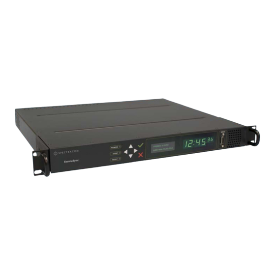
1.3.2 Status LEDs Three Status LEDs (see "SecureSync front panel layout (SAASM version)" on page 4), located on the unit's front panel, indicate SecureSync's current operating status: POWER : Green, always on while power is applied to the unit... -
Page 23: Unit Rear Panel
"Minor and Major Alarms" To troubleshoot this condition, see on page 335 Unit Rear Panel The SecureSync rear panel accommodates the connectors for all input and output references. Optional AC connection for the power input Optional DC power connector Ethernet and USB connections 1PPS output 10 MHz output... -
Page 24: Option Cards
GNSS receiver, or the optional SAASM GPS receiver module are installed. Option Cards Option Cards are circuit boards that can be installed into a SecureSync unit in order to add input and output functionality . Installation is normally done in the factory when the unit is built. - Page 25 Ethernet (NTP, PTP) Time code I/O Alarm out, etc. Functionality : Networking card (incl. NTP, PTP) Time code I/O Alarm output Special functionality e.g., revertive selector, bidirectional communication Connector type : DB-9/25 Terminal block CHAPTER • SecureSync User Reference Guide Rev. 26...
-
Page 26: Option Cards Overview
1.5.1 Option Cards Overview The table below lists all SecureSync option cards available at the time of publication of this doc- ument, sorted by their function . The table column (see table below) Web UI Name refers to the names under which the cards installed in a SecureSync unit are listed in the INTERFACES >... - Page 27 Telecom Timing Cards E1/T1 data, E1/T1 Out BNC 1.544/2.048 75 Ω MHz (1x) (3x) unbal. E1/T1 (2x) E1/T1 data, E1/T1 Out Ter- 1.544/2.048 Terminal 100/120 Ω minal MHz (1x) block, unbal. E1/T1 10-pin (2x) CHAPTER • SecureSync User Reference Guide Rev. 26...
- Page 28 (4x) HAVE QUICK HAVE QUICK Terminal out RS-485 Out, RS-485 block, 10-pin HAVE QUICK HAVE QUICK (4x) Networking Cards Gigabit Eth- Gb Ethernet (3, OR output) (3, OR input) RJ-45 ernet (3x) CHAPTER • SecureSync User Reference Guide Rev. 26...
-
Page 29: Option Card Identification
1.5.2 Option Card Identification There are several ways to identify which option card(s) are installed in your SecureSync unit: Using the Web UI, navigate to the INTERFACES > OPTION CARDS drop-down menu, and compare the list displayed in your UI with the table "Option cards identification" on page 10. - Page 30 * Every option card has a 2-digit identification ( number that can be found in the corner of its cover plate, and in the table below. The ID number is comprised of the two center digits of your option card's Spectracom Part Num- ber: 1204-0 0-0600. Figure 1-4:...
- Page 31 "Frequency Out [1204-08, -1C, -26, - 1 MHz output module (3 outputs) 1MHz Out 38]" on page 384 "IRIG In/Out [1204-05, -27]" on IRIG module, Fiber Optic (1 IRIG In/Out, page 415 input, 1 outputs) Fiber CHAPTER • SecureSync User Reference Guide Rev. 26...
-
Page 32: Option Card Connectors
"GNSS Receiver [1204-43, -44]" on Dual GNSS module Dual GNSS page 485 Receiver 1.5.3 Option Card Connectors The table below lists the connector types used in SecureSync option cards. Table 1-5: Option card connectors Connector Illustration Electr. Signals Timing signals Differential TTL xV, sine wave, programm. - Page 33 RJ-12 RS-485 data clock, CTCSS frequency, 1PPS, Alarm RJ-45 Gb-Ethernet PTP timing signal Ethernet PTP timing signal RF, differential TTL xV, sine wave, programm. 1PPS, frequency square wave, AM sine wave, DCLS CHAPTER • SecureSync User Reference Guide Rev. 26...
-
Page 34: The Securesync Web Ui
1.6 The SecureSync Web UI The SecureSync Web UI SecureSync has an integrated web user interface (referred to as "Web UI" throughout this doc- umentation) that can be accessed from a computer over a network connection, using a standard web browser. The Web UI is used to configure the unit, and for status monitoring during every- day operation. -
Page 35: The Interfaces Menu
HELP/MONITORING : Provides Spectracom Service Contact Information and high-level system configurations you may be required to furnish when contacting Spectracom Ser- vice. (If the optional TimeKeeper license is installed, this button will open the TimeKeeper Monitoring menu. See also "Status Monitoring with TimeKeeper" on page 231.) 1.6.2... -
Page 36: The Configuration Management Menu
1.6.3 The Configuration MANAGEMENT Menu The MANAGEMENT menu on the Web UI's Main screen provides access to SecureSync's con- figuration screens and settings. On the left side, under NETWORK , the following standard setup screens can be found:... -
Page 37: The Tools Menu
SNMP Trap and/or email. Time Management : Manage the Local Clock, UTC Offset, DST Definition and Leap Second information. Front Panel : Configure the appearance of the SecureSync front panel display and keypad. Log Configuration : Manage the system logs. -
Page 38: Specifications
1.7 Specifications Specifications The specifications listed below apply to the SecureSync standard model, i.e. not including any option cards, and are based on “normal” operation, with SecureSync synchronized to valid Time and 1PPS input references (in the case of GNSS input, this is with the GNSS receiver oper- ating in Stationary mode). ... -
Page 39: Gnss Receiver
Satellites tracked : Up to 72 simultaneously Update rate : up to 2Hz (concurrent) Acquisition time : Typically < 27 seconds from cold start Antenna requirements : Active antenna module, +5V, powered by SecureSync, 16 dB gain min- imum Antenna connector : Type N, female 1.7.3... -
Page 40: Protocols Supported
Low-phase noise Rubidium ±25 ns 0.2 μs 1μs Rubidium ±25 ns 0.2 μs 1μs Low-phase noise OCXO ±25 ns 0.5 μs 10 μs OCXO ±50 ns 1μs 25 μs TCXO ±50 ns 12 μs 450 μs CHAPTER • SecureSync User Reference Guide Rev. 26... -
Page 41: 10 Mhz Output
(without GPS after 2 weeks of GPS Stability lock) (p˗p) 1 sec. 10 sec. 100 sec. Low-phase noise 5x10 /month (3x10 /month 5x10 2x10 5x10 1x10 Rubidium typical) Rubidium 5x10 /month (3x10 /month 2x10 2x10 2x10 1x10 typical) CHAPTER • SecureSync User Reference Guide Rev. 26... -
Page 42: 10 Mhz Output - Oscillator Phase Noise (Dbc/Hz)
(425 mm W x 44 mm H x 364 mm D) Weight : 6.0 lbs (2.72 kg) Temperature : Operating: –20°C to +65°C Storage: –40°C to +85°C Humidity : 10% - 95% relative humidity, non-condensing @ 40°C CHAPTER • SecureSync User Reference Guide Rev. 26... -
Page 43: Regulatory Compliance
This is a Class A product. In a domestic environment this product may cause Note: radio interference in which case the user may be required to take adequate meas- ures. Safety This product has been tested and meets the requirements specified in: CHAPTER • SecureSync User Reference Guide Rev. 26... - Page 44 This product has been tested and complies with the following: 2014/30/EU Electromagnetic Compatibility (EMC) 2014/35 EU Low Voltage (LVD) 2011/65/EU on the Restriction of Hazardous Substance (RoHS2) 2014/53/EU Radio Equipment Directive (RED) Radio Spectrum Efficiency:EN 303 413 V1.1.0 CHAPTER • SecureSync User Reference Guide Rev. 26...
-
Page 45: Setup
2.9 Connecting Inputs and Outputs 2.10 Powering Up the Unit 2.11 Setting up an IP Address 2.12 Accessing the Web UI 2.13 Configuring Network Settings 2.14 Configuring NTP 2.15 Configuring Input References 2.16 Configuring Outputs CHAPTER • SecureSync User Reference Guide... -
Page 46: Overview
The option cards configuration of your unit: Is your SecureSync equipped with any option cards, such as additional input references, or additional signal distribution cards? If so, they need to be configured separately via the SecureSync Web UI, once the network configuration is complete. -
Page 47: Unpacking And Inventory
…or via serial port, using a PC with a CLI: "Setting Up an IP Address via the Serial Port" on page 51 iii. …or via Ethernet, using a PC with a web browser, and the SecureSync Web UI: "Accessing the Web UI" on page 53. Register your product: "Product Registration" on page 275. -
Page 48: Required Tools And Parts
Ethernet cables (see "Connecting Network Cables" on page 42). 2.3.1 Required GNSS Antenna Components Should you plan on using a GNSS reference with your SecureSync, you will also need: Spectracom LMR-400 antenna cable with N connectors Spectracom outdoor GNSS antenna with mounting bracket... -
Page 49: Safety
CHAPTER • SecureSync User Reference Guide Rev. 26... - Page 50 — DO NOT OPEN EQUIPMENT, UNLESS AUTHORIZED: The interior of this equipment does not have any user serviceable parts. Contact Spectracom Technical Support if this equipment needs to be serviced. Do not open the equipment, unless instructed to do so by Spectracom Service personnel.
- Page 51 Switches or other disconnection devices shall not be in the earthed circuit con- ductor between the AC and DC source and the point of the connection of the earthing electrode conductor to SecureSync’s AC and DC input power connectors earthing pin.
-
Page 52: Safety: User Responsibilities
Clearly mark the equipment to prevent its further operation. Mounting the Unit SecureSync units can be operated on a desktop or in a rack in a horizontal , right-side-up pos- ition. The location needs to be well-ventilated, clean and accessible. - Page 53 SecureSync unit. If the SecureSync unit is to be installed in a closed rack, or a rack with large amounts of other equipment, a rack cooling fan or fans should be part of the rack mount installation.
-
Page 54: Connecting Supply Power
2.6.2 Using AC Input Power Connect the AC power cord supplied in the SecureSync ancillary kit to the AC input on the rear panel and the AC power source outlet. The AC input is fuse-protected with two fuses located in the AC power entry module (line and neutral inputs are fused). -
Page 55: Using Dc Input Power
A DC power connector to attach DC power to SecureSync is included in the ancillary kit provided with the equipment. A cable of 6 feet or less, using 16AWG wire, with adequate insu- lation for the DC voltage source should be used with this connector. The cable clamp provided with the DC power plug for strain relief of the DC power input cable should be used when DC power is connected to SecureSync. - Page 56 Spectracom recommends to use a dedicated DC power supply switch to energize/de-energize SecureSync externally. DC power connector pin-out SecureSync units can be ordered in a DC version that includes the following DC plug on the back panel: DC Plug, 3-pin, chassis mount: Amphenol P/N DL3102A10SL-3P DC ancillary kit...
-
Page 57: Connecting The Gnss Input
Pin C goes to the Earth ground of the DC source. AC/DC Converter The DC input can be used as a second AC input: As an option, Spectracom offers a kit con- taining an AC/DC converter with a pre- assempled DC connector: The part number for this adaptor kit is PS06R-2Z1M-DT01 . -
Page 58: Connecting Network Cables
GNSS is Enabled , and its Status for TIME and 1PPS is valid (green). Connecting Network Cables SecureSync provides a base 10/100 Ethernet port for full NTP functionality, as well as a com- prehensive web-based user interface ("Web UI") for configuration, monitoring and diagnostic support. -
Page 59: Connecting Inputs And Outputs
Connecting Inputs and Outputs SecureSync can synchronize not only to an external GNSS reference signal, but also to other optional external references such as IRIG, HAVE QUICK and ASCII inputs (in addition to net- work based references such as NTP and/or PTP). -
Page 60: Setting Up An Ip Address
2.11 Setting up an IP Address In order for SecureSync to be accessible via your network, you need to assign an IP address to SecureSync, as well as a subnet mask and gateway, unless you are using an address assigned by a DHCP server. -
Page 61: Dynamic Vs. Static Ip Address
SecureSync's hostname instead of IP address), Spectracom recommends to disable DHCP for SecureSync, and instead use a static IP address. Failure to do this can result in a loss of time synchronization, should the DHCP server assign a new IP address to SecureSync. -
Page 62: Assigning A New Static Ip Address
DHCP address, see "Setting Up a Static IP Address via a DHCP Network" on page 50. By connecting a Personal Computer to SecureSync via a serial cable , see "Setting Up an IP Address via the Serial Port" on page 51. - Page 63 For more information on using the serial port connection, see "Setting up a Terminal Emulator" on page 512. The serial port is account and password protected. Login to SecureSync with a user account that has “admin” group rights, such as the default...
-
Page 64: Setting Up An Ip Address Via The Front Panel
2.11.2.2 Setting Up an IP Address via the Front Panel Assigning an IP address to SecureSync, using the front panel keypad and information display is a preferred way to provide network access to the unit, thus enabling you thereafter to com- plete the setup process via the Web UI. - Page 65 The display will change, allowing you to input an address at N=000.000.000.001. Enter the gateway address here. The address entered must correspond to the same network IP address assigned to SecureSync. Enable/disable the Port (if required) Still on the...
-
Page 66: Setting Up A Static Ip Address Via A Dhcp Network
Enter the IP address shown on the front panel information display of your SecureSync unit into the address field of your browser (on a computer connected to the SecureSync network). If the network supports DNS, the hostname may also be entered instead (the default hostname is "Spectracom"). -
Page 67: Setting Up An Ip Address Via The Serial Port
The serial port is account and password protected. You can login via the serial port using the same user names and passwords as would be used to log into the SecureSync Web UI. Users with “administrative rights” can perform all available commands. Users with “user” permissions only can perform “get”... -
Page 68: Setting Up A Static Ip Address Via Ethernet Cable
2.11.2.5 Setting up a Static IP Address via Ethernet Cable This procedure will allow you to configure SecureSync using the Web UI directly via the Eth- ernet port, if for some reason you prefer not to (or cannot) use a DHCP network. -
Page 69: Subnet Mask Values
You can access the Web UI either by using the automatically assigned DHCP IP address, or by using a manually set static IP address (see "Assigning a Static IP Address" on page 45): On a computer connected to the SecureSync network, start a web browser, and enter the IP address shown on the SecureSync front panel. - Page 70 "Managing Passwords" on page 251. Upon initial login, you will be asked to register your product. Spectracom recommends to register SecureSync, so as to receive software updates and services notices. See also "Product Registration" on page 275. Number of login attempts The number of failed login attempts for ssh is hard-set to (4) four. This value is not configurable.
-
Page 71: Configuring Network Settings
Access Control : Allows the configuration of access restrictions from assigned net- works/nodes. Login Banner : Allows the administrator to configure a custom banner message to be displayed on the SecureSync Web UI login page and the CLI (Note: There is a 2000 character size limit). CHAPTER •... -
Page 72: General Network Settings
TABLE button: Displays a window that allows adding, editing, and reviewing Static Routes. 2.13.1 General Network Settings To expedite network setup, SecureSync provides the General Settings window, allowing quick access to the primary network settings. To access the General Settings window: Navigate to MANAGEMENT >... -
Page 73: Network Ports
Hostname : This is the server’s identity on the network or IP address. The default is Spectracom Default Gateway IPv6 : The gateway (default router) address is needed if com- munication to the SecureSync is made outside of the local network. By default, the gateway is disabled in the format “ ” where each ‘... - Page 74 2.13 Configuring Network Settings Note: eth0 port is the built- in SecureSync Ethernet port (i.e., standard, not optional). If the port is not already enabled, in the Edit Ethernet Ports Settings window, click the Enable check box. The Edit Ethernet Ports Settings window will expand to show the options needed to complete the port setup.
- Page 75 Mask Values" on page 53 for a list of subnet mask values. IPv4 Gateway : The gateway (default router) address is needed if communication to the SecureSync is made outside of the local net- work. By default, the gateway is disabled.
-
Page 76: Network Services
To apply your changes, click Submit (the window will close), or Apply . 2.13.3 Network Services Several standard network services can be enabled or disabled via the easily accessible Net- work Services Panel under MANAGEMENT > Network Setup : CHAPTER • SecureSync User Reference Guide Rev. 26... - Page 77 Classic UI : This toggle switch allows the SecureSync Classic User Interface (as used in SecureSync Web UI Version 5.0.2 and older) to be turned ON or OFF [Default = OFF]. To enable, select the ON position, and refresh the browser window (the refresh may take a moment).
-
Page 78: Static Routes
While not accessible via the Web UI, iptables (an application allowing for customizable access restrictions) have been supported since SecureSync Software Version 5.4.1. Note that iptables is always ON, and its policies can only be accessed via the Command Line Interface (see "CLI Commands"... - Page 79 Note: eth0 port is the default port for static routing. If a port is not given its own static route, all packets from that port will be sent through the default. CHAPTER • SecureSync User Reference Guide Rev. 26...
-
Page 80: Access Rules
IPv6— , representing 2001:db8::/48 2001:db8:0:0:0:0:0:0 2001:d- b8:0:ffff:ffff:ffff:ffff:ffff. Click the Add button in the Action column to add the new rule. The established rule appears in the Network Access Rules window. CHAPTER • SecureSync User Reference Guide Rev. 26... -
Page 81: Https
Note: In order to configure HTTPS, you need ADMINISTRATOR rights. Note that SecureSync supports two different modes of HTTPS operation: The Standard HTTPS Level (default), and a High-Security Level . For more information, see "HTTPS Security Levels" on page 266. - Page 82 Certificate Authority. Upload X.509 PEM Certificate : Use the window under this tab to paste your X.509 certificate text and upload it to SecureSync. Upload Certificate File : Use this tab to upload your certificate file returned by the Cer- tificate Authority.
-
Page 83: About Https
2.13.6.3 Supported Certificate Formats SecureSync supports X.509 PEM and DER Certificates, as well as PKCS#7 PEM and DER format- ted Certificates. You can create a unique X.509 self- signed Certificate, an RSA private key and X.509 cer- tificate request using the Web UI. -
Page 84: Creating An Https Certificate Request
Spectracom default Certificate) will be Note that an invalid Certificate may result in denial of access to SecureSync via the Web UI! (If this occurs, see "If a Secure Unit Becomes Inaccessible" on page 268.) Fill in the available fields:... - Page 85 RSA Private Key Bit Length : 2048 bits is the default. Using a lower number may compromise security and is not recommended. Two-Letter Country Code : This code should match the ISO-3166-1 value for the country in question. CHAPTER • SecureSync User Reference Guide Rev. 26...
- Page 86 It is recommended that you consult your Certificate Authority for the required fields in an X 509-Certificate request. Spectracom recommends all fields be filled out and match the information given to your Certificate Authority. For example, use all abbreviations, spellings, URLs, and company departments recognized by the Certificate Authority.
-
Page 87: Adding Https Subject Alternative Names
Certificate Authority. Note: It may take several minutes for SecureSync to create the Certificate request and the private key (larger keys will require more time than small keys). If the unit is rebooted during this time, the Certificate will not be cre- ated. - Page 88 URL used to reach the host via HTTPS. After completing and submitting the form, view the Subject Alternative Name tab to see existing entries. Existing Subject Alternative Names can be edited or deleted from this window. CHAPTER • SecureSync User Reference Guide Rev. 26...
-
Page 89: Requesting An Https Certificate
Certificate Request previously generated once you submit it. Therefore, if you wish to retain your previously generated Certificate Request for any reason, copy its text, and paste it into a separate text file. Save the file before generating a new request. CHAPTER • SecureSync User Reference Guide Rev. 26... -
Page 90: Uploading An X.509 Pem Certificate Text
It will be displayed under the Certificate Request tab. You may use your self-signed certificate (or the default Spectracom self-signed certificate that comes with the unit) while waiting for the HTTPS certificate from the Certificate Authority, or – if a Certificate Authority is not available –... -
Page 91: Uploading An Https Certificate File
However, changes should not be made to a Certificate once it is imported; instead, a new Cer- tificate should be requested. An invalid Certificate may result in denial of access to the SecureSync through the Web UI. If this occurs, see "If a Secure Unit Becomes Inaccessible" on page 268. -
Page 92: Ssh
Authority in its location where you stored it in step 1. Click Submit . Note: SecureSync will automatically format the Certificate into the X.509 PEM format. Certificate Chain It is possible to upload a X.509PEM Certificate Chain file. Note that there should be no char- acter between the Certificate texts. - Page 93 The SSH tools supported by SecureSync are: SSH : Secure Shell SCP : Secure Copy SFTP : Secure File Transfer Protocol SecureSync implements the server components of SSH, SCP, and SFTP. www.openssh.org For more information on OpenSSH, please refer to To configure SSH: Navigate to MANAGEMENT >...
- Page 94 Host Keys can be created. SecureSync units have their initial host keys created at the factory. RSA host key sizes can vary between 768 and 4096 bits. The recommended key size is 1024. Though many key sizes are supported, it is recommended that users select key sizes that are powers of 2 or divisible by 2.
- Page 95 Deleting Host Keys You can delete individual host keys. To delete a key: Navigate to MANAGEMENT > NETWORK: SSH Setup . The window will open to the Host Keys tab by default. CHAPTER • SecureSync User Reference Guide Rev. 26...
- Page 96 The Host keys are generated in the background. Creating RSA and DSA keys, each with 1024 bits length, typically takes about 30 seconds. Keys are cre- ated in the order of RSA, DSA, ECDSA, ED25519. SecureSync will generate all 4 host keys, RSA, DSA, ECDSA, and ED25519.
- Page 97 Load a public key into SecureSync. This public key must match the private key found in the users account and be accessible to the SSH, SCP, or SFTP client program. The user must then enter the Passphrase after authentication of the keys to provide the second factor for 2-factor authentication.
- Page 98 Creating an SSH session using Public Key with Passphrase Authentication for the admin account You must first provide the secure Spectracom product a RSA public key found typically in the OpenSSH id_rsa.pub file. Then you may attempt to create an SSH session.
- Page 99 SSH protocols, and provide user private keys. Secure File Transfer Using SCP and SFTP SecureSync provides secure file transfer capabilities using the SSH client tools SCP and SFTP. Authentication is performed using either Account Passwords or Public Key with Passphrase.
-
Page 100: Snmp
2.13 Configuring Network Settings Recommended SSH Client Tools Spectracom does not make any recommendations for specific SSH clients, SCP clients, or SFTP client tools. However, there are many SSH based tools available to the user at low cost or free. - Page 101 Traps" on page 91 and "Setting Up SNMP Notifications" on page 244. The Actions panel , which contains the Restore Default SNMP Configuration button. The SNMP Status panel , which offers: An SNMP ON/OFF switch. An Authentication Error Trap ON/OFF switch. CHAPTER • SecureSync User Reference Guide Rev. 26...
- Page 102 Description —A simple product description. This is not editable in the SNMP Status. Restoring the Default SNMP Configuration To restore the SecureSync to its default SNMP configuration: Navigate to the MANAGEMENT > NETWORK: SNMP Setup screen. In the Actions panel, click the Restore Default SNMP Configuration button.
- Page 103 Accessing the SNMP Support MIB Files Spectracom’s private enterprise MIB files can be extracted via File Transfer Protocol (FTP) from SecureSync, using an FTP client such as FileZilla or any other shareware/freeware FTP pro- gram. To obtain the MIB files from SecureSync via FTP/SFTP: Using an FTP program, log in as an administrator.
-
Page 104: Snmp V1/V2C
2.13 Configuring Network Settings Spectracom’s private enterprise MIB files can be requested and obtained from the Spec- techsupport@spectracom.com tracom Customer Service department via email at techsupport@spectracom.com Note: By default, is the address in the sysContact field of the SNMP Status panel of the SNMP Setup page. - Page 105 2.13 Configuring Network Settings If no value is entered in the IPv4 and/or IPv6 field, SecureSync uses the system default address. SNMP Community names should be between 4 and 32 characters in length. Permissions may be Read Only or Read/Write.
-
Page 106: Snmp V3
User names are arbitrary. SNMP User Names should be between 1 and 31 characters in length. The User Name must be the same on SecureSync and on the management station. The Auth Type field provides a choice between MD5 and SHA. -
Page 107: Snmp Traps
. A varbind provides a current SecureSync data object that is related to the specific trap that was sent. For example, when a Holdover trap is sent because SecureSync either entered or exited the Holdover mode, the trap varbind will indicate that SecureSync is either currently in Holdover mode or not currently in Holdover mode. - Page 108 [v3] Should you require the Engine ID of your unit in order to decode traps sent to an NNMI, you can use an SNMPv3 .1.3.6.1.3.10.2.1.1 "get" value of to poll your Engine ID. CHAPTER • SecureSync User Reference Guide Rev. 26...
-
Page 109: System Time Message
The System Time Message is a feature used for special applications that require a once-per- second time message to be sent out by SecureSync via multicast. This time message will be trans- mitted before every 1PPS signal, and can be used to evaluate accuracy and jitter. -
Page 110: System Time Message Format
Unsigned 32 bit Bytes Size integer Seconds Seconds since epoch (00:00:00 Jan 1, Unsigned 32 bit Seconds 1970 UTC) integer NSec NSec within the current second Unsigned 32 bit nsec integer End-of-message CHAPTER • SecureSync User Reference Guide Rev. 26... -
Page 111: Configuring Ntp
When the NTP service is enabled, SecureSync will “listen” for NTP request messages from NTP clients on the network. When an NTP request packet is received, SecureSync will send an NTP response time packet to the requesting client. Under typical conditions, SecureSync can service several thousand NTP requests per second without MD5 authentication enabled, and at a some- what lower rate with MD5 authentication enabled. - Page 112 It is through this display that you configure external NTP references. See "NTP Servers: Adding, Configuring, Removing" on page 107. NTP Peers : In this display you can view the NTP Peers that SecureSync detects in your net- work. It is through this display that you configure NTP Peer reference inputs. See "NTP Peers: Adding, Configuring, Removing"...
- Page 113 IP Version IP Mask Auth only Enable Query View NTP Clients : Click here to reveal a table of all the clients your SecureSync is ser- vicing. (See also "Viewing NTP Clients" on page 99.) Information for each client includes: Client IP...
-
Page 114: Dis-/Enabling Ntp
NTP Service automatically once you clicked Submit. Changes made to NTP configurations will also take effect after SecureSync is either rebooted or power-cycled. You can, however, also disable or enable the SecureSync NTP Service manually, e.g. with NTP Autokey. -
Page 115: Viewing Ntp Clients
Changes made will now take effect and NTP operation will be restored shortly after this oper- ation is performed. 2.14.4 Viewing NTP Clients To view the NTP clients being served by SecureSync: Navigate to MANAGEMENT> NETWORK: NTP Setup . In the NTP Actions panel, click View NTP Clients :... -
Page 116: Restoring The Default Ntp Configuration
In the dialog window that displays, click OK . 2.14.6 NTP Output Timescale You can choose the timescale SecureSync will use for the time stamps it sends out to its NTP cli- ents and network nodes. This is done by setting SecureSync System Time timescale. The options are UTC, TAI and GPS. - Page 117 NTP, logging, and time displayed on the unit front panel and in the Web UI. If SecureSync is operated as a Stratum 2 server, i.e. as a client to a Stratum 1 server (see "Con- figuring "NTP Stratum Synchronization"" on page 103 ), the other server will override SecureSync's System Timescale, should it be different.
-
Page 118: Ntp Reference Configuration
2.14 Configuring NTP 2.14.7 NTP Reference Configuration SecureSync's NTP Service needs to be setup such that it utilizes the time source ("input ref- erence") you want it to use. There are two options for an NTP Server to derive its time from: The NTP Service uses SecureSync's System Time, i.e. -
Page 119: Configuring "Ntp Stratum Synchronization
2.14 Configuring NTP use the System Time as a reference to NTP, since this provides NTP with the most accurate ref- erences. This mode is called Stratum 1 operation, since SecureSync operates as a Stratum 1 NTP server. To configure Stratum 1 operation for SecureSync: Navigate to MANAGEMENT >... -
Page 120: Ntp Servers And Peers
Server or Peer will normally be used at all times. Spectracom, however, recommends to check this box, thus allowing the NTP Ser- vice to use SecureSync's System Time during Holdover , i.e. if the external NTP ref- erence has become unavailable. Prefer Stratum 1 Uncheck this option to prevent SecureSync's NTP service from “weighing”... - Page 121 (i.e., NTP Peers) but is currently using a different input reference as its selected reference, SecureSync will report to the network (via the NTP time stamps) that it is a Stratum 1 time server. Should, however, all input references except the other NTP server (s) become unavailable, SecureSync will then drop to a Stratum 2 time server (with System Time being derived from the...
-
Page 122: The Ntp Servers And Ntp Peers Panels
REF ID : Identifies the type of Input REFerence e.g., GPS indicates the reference can use GPS for its synchronization. Below is a list of potential REF IDs reported by the SecureSync Timing System (other NTP Servers and Peers may report different ref- erences):... -
Page 123: Ntp Servers: Adding, Configuring, Removing
LAST : The number of seconds that have expired since this reference was last polled for its time. POLL : The polling interval, i.e. how often SecureSync is polling this NTP reference for its time. DELAY (ms) : The measured one-way delay between SecureSync and its selected ref- erence. - Page 124 Key-ID/Key string pairs or the use of Auto-Key. However, these choices are mutu- ally exclusive and must be identically configured on both the SecureSync and the NTP Peer or NTP Server. If the Symmetric Key-ID/Key string pair method is selec- ted the Key-ID must be first defined on the Symmetric Key page.
-
Page 125: Ntp Peers: Adding, Configuring, Removing
NTP Peer, click the PLUS icon in the top right corner of the NTP Peers panel. an NTP Peer (and its associated configurations), click the X-button REMOVE next to it. The NTP Peers edit window opens: CHAPTER • SecureSync User Reference Guide Rev. 26... - Page 126 However, these choices are mutually exclusive and must be figured on both the SecureSync and the NTP Peer or NTP Server. If the Sym- metric Key-ID/Key string pair method is selected the Key-ID must be first defined on the Symmetric Key page.
-
Page 127: Ntp Authentication
Currently, SecureSync supports only the IFF (Identify Friend or Foe) Autokey Identity Scheme. The SecureSync product web interface automates the configuration of the IFF using the MD5 digests and RSA keys and certificates. At this time the configuration of other key types or other digests is not supported. - Page 128 Passphrases can be identical for all group members and Client NTP Serv- Note: ers. Or passphrases can be the same for group members and a different pass- phrase shared between the Client Only NTP Servers. CHAPTER • SecureSync User Reference Guide Rev. 26...
- Page 129 When you configure NTP Autokey, you must disable the NTP Service first, and then re- enable it after Autokey configuration is completed. See "Dis- /En- abling NTP" on page 98. To configure NTP Autokey: CHAPTER • SecureSync User Reference Guide Rev. 26...
- Page 130 2. Click the Submit button. A Groupkey is then generated for the network. This Groupkey will be pasted into the Group- key box to designate another server on the network as Client or Server. CHAPTER • SecureSync User Reference Guide Rev. 26...
- Page 131 2.14 Configuring NTP To designate a SecureSync as Trusted , click the Submit button. This will generate a new Groupkey . To designate a SecureSync as a Client or a Server , paste the generated Groupkey into the Groupkey box, and click the Submit button.
- Page 132 Select Certificate Type to Generate —Select Client to enable Client only. Using the NTP Server containing the IFF Group/Client Key, copy the Group/Client key. Paste this Group/Client key into the Autokey Groupkey text box. CHAPTER • SecureSync User Reference Guide Rev. 26...
-
Page 133: Ntp: Symmetric Keys (Md5)
Symmetric Keys are an encryption means that can be used with NTP for authentication pur- poses. SecureSync supports authenticated NTP packets using an MD5 authenticator. This feature does not encrypt the time packets, but attaches an authenticator, which consists of a key identifier and an MD5 message digest, to the end of each packet. - Page 134 Note: To use the MD5 authentication with trusted key ID, both the NTP client and the SecureSync must contain the same key ID/key string pair, the client must be set to use one of these MD5 pairs, and the key must be trusted.
-
Page 135: Ntp Access Restrictions
NTP response with its own valid authenticator using the same Key ID provided in the NTP request. You may define the trusted Symmetric Keys that must be entered on both SecureSync, and any network client with which SecureSync is to communicate. Only those keys for which the “Trus- ted”... - Page 136 PLUS icon or the Change button, respectively, and proceed to Step 4. below. DELETE an access restriction, click the corresponding Delete button, and con- firm by clicking OK. The NTP Access Restrictions window will display: CHAPTER • SecureSync User Reference Guide Rev. 26...
-
Page 137: Enabling/Disabling Ntp Broadcasting
Click the Submit button. 2.14.11 Enabling/Disabling NTP Broadcasting The NTP Broadcast mode is intended for one or a few servers and many clients. SecureSync allows the NTP service to be configured to broadcast the NTP time only to the network’s broad- cast address at scheduled intervals. -
Page 138: Ntp Over Anycast
Anycast address, thus avoiding the need to configure every client indi- vidually. NTP over Anycast , as implemented in SecureSync, is a combination of the two concepts, allow- ing SecureSync to: Associate one of its network ports to an Anycast IP address, and Remove itself as an available time source if its reference is lost or degraded, and vice versa. -
Page 139: Configuring Ntp Over Anycast (General Settings)
NTP over Anycast address. As soon as the first SecureSync server obtains a valid reference again, it will make itself available to the OSPF router, which will then use it as a time source again, based on the principle of shortest path available. -
Page 140: Configuring Ntp Over Anycast (Ospf Ipv4)
Confirm that your existing network infrastructure is Anycast capable, and uses OSPF Ver- sion 2 (IPv4). Determine the OSPF area. In the SecureSync Web UI, navigate to MANAGEMENT > Network > NTP Setup . In the Actions Panel , click NTP over Anycast . -
Page 141: Configuring Ntp Over Anycast (Ospf Ipv6)
Navigate to Management > Disciplining , and click the GEAR icon in the top-right corner of the Status panel. Set the value Maximum TFOM for Sync to 4 (this will make SecureSync to go out of sync if the phase error is greater than 1μs). -
Page 142: Configuring Ntp Over Anycast (Bgp)
Navigate to Management > Disciplining , and click the GEAR icon in the top-right corner of the Status panel. Set the value Maximum TFOM for Sync to 4 (this will make SecureSync to go out of sync if the phase error is greater than 1μs). -
Page 143: Configuring Anycast Via Ntp Expert Mode
Navigate to Management > Disciplining , and click the GEAR icon in the top-right corner of the Status panel. Set the value Maximum TFOM for Sync to 4 (this will make SecureSync to go out of sync if the phase error is greater than 1μs). - Page 144 Interface eth1 line, followed by only IPv6 line, because no IPv4 address is configured on that port) ***************************************************** interface eth0 ip address 10.2.100.157/16 interface eth1 ipv6 address 2000:10:2::157/64 interface lo ip address 10.10.14.1/32 ipv6 address 2000:10:10::1/64 CHAPTER • SecureSync User Reference Guide Rev. 26...
- Page 145 10.10.14.1/32 access-list default deny any ***************************************************** Example ospf6d.conf file: ***************************************************** interface eth0 router ospf6 router-id 10.2.100.157 interface eth0 area 0.0.0.0 redistribute connected ***************************************************** Example bgpd.conf file: *****************************************************! CHAPTER • SecureSync User Reference Guide Rev. 26...
-
Page 146: Testing Ntp Over Anycast
Please contact 2.14.13 NTP Orphan Mode The NTP Orphan Mode allows SecureSync to remain a valid time server to its NTP clients even if all its input references have become invalid and the Holdover period has expired. Per default, SecureSync will automatically downgrade itself to NTP Stratum 15 , should its input references become invalid and after expiration of the Holdover period. -
Page 147: Host Disciplining
2.14.14 Host Disciplining Host Disciplining allows an NTP input reference to discipline SecureSync's oscillator. This may be utilized e.g., with SecureSync units that do not have a GPS receiver because they are oper- ated as Stratum 2 servers. In general, it is advisable to enable Host Disciplining only if needed, and to use it only in robust networks/NTP environments. -
Page 148: Enabling Host Disciplining
While disabled Host Disciplining does not offer the benefit of a disciplined oscillator when transitioning into or out of holdover, SecureSync on the other hand will not be sus- ceptible to disciplining errors caused by network traffic or NTP-related issues. - Page 149 Normally, configuration of this file is NTP.conf indirectly performed by a user via the integrated configuration pages of the SecureSync Web UI. However, it may be desired in certain circumstances to edit this file directly, instead of using the web-based setup screens.
- Page 150 Expert mode restores these tabs to the Edit NTP Services window. To enable the Expert Mode, and edit the file: NTP.conf Navigate to MANAGEMENT > NETWORK: NTP Setup . In the NTP Services panel locate the Expert Mode switch: CHAPTER • SecureSync User Reference Guide Rev. 26...
-
Page 151: Spectracom Technical Support For Ntp
Click the Submit button to save any changes that were made. Disable and then re-enable the NTP service using the NTP ON/OFF switch in the NTP Ser- vices panel. SecureSync will now use the new NTP configuration per the manually edited file. -
Page 152: Configuring Input References
The illustrations shown below are examples. The windows displayed in your Note: Web UI may look differently. Editing output settings, method 1: CHAPTER • SecureSync User Reference Guide Rev. 26... -
Page 153: The Outputs Screen
2.16.1 The Outputs Screen SecureSync outputs deliver a time or frequency signal to a device that consumes this signal. To access the Outputs screen in the Web UI: Navigate to INTERFACES and click on OUTPUTS (white on orange). -
Page 154: The 1Pps And 10 Mhz Outputs
If you hover with your mouse pointer over any of the connectors shown in the rear panel illustration, a tooltip will be displayed, indicating the type of output.. If you have only one output of any type, SecureSync will number that output 0. Additional outputs will be numbered 1 or above. - Page 155 SecureSync’s 1PPS output is generated from the oscillator’s 10 MHz output and is aligned to the on-time point. The on-time point of the 1PPS output can be configured to be either the rising or falling edge of the 1PPS signal (by default, the rising edge is the on-time point).
-
Page 156: Configuring A 1Pps Output
Navigate to INTERFACES > OUTPUTS , or to INTERFACES > OPTION CARDS (white on orange). In the panel on the right, click the GEAR button next to the 10 MHz output that you want to edit. CHAPTER • SecureSync User Reference Guide Rev. 26... -
Page 157: Configuring Optional Outputs
You can setup Signature Control such that SecureSync's built in 1PPS output becomes disabled the moment its input reference is lost (e.g., if a valid GNSS signal is lost). Or, you can setup your output signal such that remains valid while SecureSync in holdover mode, but not in free run. - Page 158 2.16 Configuring Outputs Output Enabled in Holdover —The output is present unless SecureSync is not synchronized to its references (SecureSync is in Holdover mode). III. Output Disabled in Holdover —The 1PPS output is present unless the SecureSync ref- erences are considered not qualified and invalid (the output is NOT present while SecureSync is in Holdover mode.)
- Page 159 2.16 Configuring Outputs In the Outputs panel, click the GEAR button for the desired output. Ehe Edit window will open with the current Signature Control setting, and a drop-down list to change it. CHAPTER • SecureSync User Reference Guide Rev. 26...
- Page 160 2.16 Configuring Outputs BLANK PAGE. CHAPTER • SecureSync User Reference Guide Rev. 26...
-
Page 161: Managing Time
Managing Time In this document, the notion of Managing Time refers not only to the concept of SecureSync's System Time, but also to reference con- figuration, as well as distribution of time and frequency. The following topics are included in this Chapter: 3.1 The Time Management Screen... -
Page 162: The Time Management Screen
Via the Leap Second Info panel, leap second corrections can be applied to SecureSync’s time keeping. It is also possible to enter the exact day and time when the leap second is to be applied, and to delete a leap second. -
Page 163: System Time
(Real Time Clock) as System Time (with an external 1PPS reference). The flow chart below illustrates how SecureSync obtains the highest available and valid ref- erence, depending on whether an external source is chosen as reference, or an internal ( User [x] , or Local System ). -
Page 164: System Time
GMT (Greenwich Mean Time) is a time zone that is used in several European and African countries as the official local time. CHAPTER • SecureSync User Reference Guide Rev. 26... -
Page 165: Timescales
"System Time" on the previous page. Input timescales Some of the inputs may not necessarily provide time to SecureSync in the same timescale selec- ted in the System Time’s timescale field. These inputs have internal conversions that allow the timescale for the inputs to also be independently defined, so that they don’t have to be... -
Page 166: Manually Setting The Time
Otherwise, a System Time error may occur! Output timescales Some of the available SecureSync outputs (such as the front panel LED display, the IRIG option module’s outputs, ASCII data module’s outputs, etc.) won’t necessarily output in the same times- cale selected in the System Time’s timescale field. - Page 167 NOTE: Except for testing purposes, you should not choose a date other than the current day. Set Year Only : Some legacy time formats (e.g., IRIG) do not support years. Check- ing this box will open a data entry field to manually set the year. Spectracom CHAPTER •...
-
Page 168: Using Battery Backed Time On Startup
Battery Backed Time is also referred to as the time maintained by the integrated Real Time Clock ( RTC ) This will result in SecureSync providing a System Time before one of the external references becomes available and valid. This will happen automatically, i.e. without user intervention. As soon an external reference will become available, its time will take precedence over the battery backed time: The System Clock will adjust the System Time for any time difference. - Page 169 In a non-autonomous system (i.e, when using external reference(s)) SecureSync's System Clock will regularly update the battery-backed time. Another factor impacting the accuracy of the battery-backed time is how long a SecureSync unit is powered off: Any significant amount of time will cause the battery-backed RTC to drift, i.e.
-
Page 170: Timescale Offset(S)
In the Offsets panel on the left, click the GEAR icon in the top-right corner. The Edit GPS Offset window will display. Enter the desired GPS Offset in seconds, and click Submit. CHAPTER • SecureSync User Reference Guide Rev. 26... -
Page 171: Leap Seconds
As of 2018 the GPS to UTC Offset is 18 seconds. The last Leap Second occurred on December 31, 2016. SecureSync can be alerted of impending Leap Seconds by any of the following methods: Intercalary: (of a day or a month) inserted in the calendar to harmonize it with the solar year, e.g., February 29 in leap years. -
Page 172: Leap Second Alert Notification
3.2.3.3 Leap Second Correction Sequence The following is the time sequence pattern in seconds that SecureSync will output at UTC mid- night on the scheduled day (Note: This is NOT local time midnight; the local time at which the CHAPTER •... -
Page 173: Configuring A Leap Second
In the lower left-hand corner, the Leap Second Information panel will show if a leap second if pending. This panel will be empty, unless: A leap second is pending, and SecureSync has obtained this information auto- matically from the GPS data stream. -
Page 174: Local Clock(S), Dst
This name will be used as cross-reference drop-down in the applicable Input or Output port configuration. Please note the following limitations apply to this option: Note: Acceptable characters for the name include: A-Z, a-z, 0-9, (- +_) and space. CHAPTER • SecureSync User Reference Guide Rev. 26... - Page 175 “DST out” date is the first Sunday of November). Australia . Note: If a pre-configured rule DST rule happens to be changed in the future (like the change to the US DST rule in 2006), this option CHAPTER • SecureSync User Reference Guide Rev. 26...
-
Page 176: Dst Examples
E x a m p l e 2 : To create a Local Clock for a SecureSync installed in the Eastern Time Zone of the US, and desiring the Local Clock to automatically adjust for DST (using the post 2006 DST rules for the US). -
Page 177: Dst And Utc, Gmt
Actions panel, in order to update the table with the new reference information. In order for SecureSync to declare synchronization, it needs both a valid 1PPS , and Time ref- erence. The concept of Reference Priority allows the ranking of multiple references for redundancy. This... - Page 178 Note: The References shown on your screen may look different from the ones in the illustration below, depending on your SecureSync Time and Frequency Syn- chronization System model and hardware configuration. Each available type of Time and 1PPS input reference is assigned a human-readable name or “title”...
-
Page 179: Configuring Input Reference Priorities
SecureSync can use numerous external time sources, referred to as "references". As external time sources may be subject to different degrees of accuracy and reliability, you can determine in which order (= priority) SecureSync calls upon its external time and 1PPS references. For additional information, see also "Input Reference Priorities" on page 161. - Page 180 The Reference Status panel The Reference Status panel provides a real time indicator of the status of the SecureSync’s references. It is the same as the Reference Status panel on the HOME screen of the Web UI. Adding an Entry to the Reference Status Table To add a new entry to the Reference Status table: Navigate to the Configure Reference Priorities screen via MANAGEMENT >...
- Page 181 Navigate to the Configure Reference Priorities screen via MANAGEMENT > OTHER: Refer- ence Priority . Click and hold on the item whose priority you wish to reorder. Drag the item up or down to the desired place. CHAPTER • SecureSync User Reference Guide Rev. 26...
-
Page 182: The "Local System" Reference
3.3.1.2 The "Local System" Reference The Local System reference is a "Self" reference, i.e. SecureSync uses itself as an input ref- erence for Time, or as a 1PPS reference. The Local System is a unique input reference in that it... -
Page 183: The "User/User" Reference
3.3 Managing References Vice versa, when the 1PPS reference is configured as Local System , SecureSync's built-in oscillator is considered a valid reference, as long as the external Time reference is valid. Use case "Local System Time" The Local System reference when used for... - Page 184 User/User reference, the hand-set time must be green manually submitted every time after SecureSync reboots or resets, or after the Holdover period has expired: In the Edit System Time window, the checkbox Manual Time Set must be checked.
-
Page 185: Reference Priorities: Examples
Move the reference which has “IRIG 0” in both the Time column and “IRIG 0” in the 1PPS column to the top of the table, with a Priority value of 1. Click the Enabled checkbox. CHAPTER • SecureSync User Reference Guide Rev. 26... - Page 186 Priority table. "The "User/User" Reference" on page 167. In this use case, the objective is to use a hand-set time, in combination with SecureSync's oscil- lator as a 1PPS source as valid references. Step-by-step procedure: If necessary (see NOTE above), create a “User.”...
- Page 187 Example 5—Time at power-up ("Local System Time") to be considered "Valid". GNSS input to serve as 1PPS reference The objective of this use case is to allow SecureSync to use itself as a valid reference. This is referred to as “Local System” time.
-
Page 188: Reference Qualification And Validation
(see "Smart Reference Monitoring" on the facing page). SecureSync allows Reference Monitoring by comparing the phase data of references against the System Ontime Point. The phase values shown are the filtered phase differences between each input reference 1PPS, and the internal disciplined 1PPS. - Page 189 The thresholds are not user-configurable. If the higher threshold value is exceeded, the automatic failover will cause SecureSync to fall back to its next lower reference (if available).
-
Page 190: Broadshield
3.3.2.2 BroadShield What is BroadShield? BroadShield is an optional software module for SecureSync that is capable of detecting the presence of GPS jamming or spoofing in real time. How BroadShield Works BroadShield monitors the GPS signal frequency band by applying proprietary error detection algorithms. - Page 191 Major Alarm, however it will continue to consider the GNSS reference as valid, i.e. it will NOT go out of sync. Auto Sync Control : In the event jamming or spoofing is detected, SecureSync will emit a Major Alarm AND it will go into Holdover mode.
- Page 192 Click SETTINGS to open the following sub-menus: BROADSIGHT BroadSight is a service that allows collection of data from multiple BroadShield units and provides a dashboard view of the data. Note: BroadSight for SecureSync is currently not supported. CHAPTER • SecureSync User Reference Guide Rev. 26...
- Page 193 A less common use case may be that you want to pre-set the unit's position for later use e.g., if the SecureSync unit will be deployed in a different location: Set a position manually by enter- ing lat / long (format: xx.xxxxxx degrees) and alt . Note, however, that this may cause a spoof- ing alarm, since BroadShield detects a difference between the HOME BASE position and the GNSS position.
- Page 194 SecureSync system software updates, as they become available. Monitoring BroadShield You can use the BroadShield Web UI to monitor the jamming/spoofing status, or the SecureSync Web UI. In the latter case, you will be informed of a Major Alarm, as described below: BroadShield Alarm...
- Page 195 Critical zone indicates a poten- blue tial jamming incident, while a green line indicates that SecureSync may be subject to a spoof- ing attack. You can change the time scale by clicking on any of the labels between 1 HOUR 7 DAY...
- Page 196 3.3 Managing References Note: A SecureSync reboot will reset all history data (it can still be retrieved via LOGS.) Bottom graph The bottom graph labeled Spectrum visualizes the current signal over the GPS frequency band. Unusual amplitude spikes indicate a potential threat. If your system is equipped with more than one GNSS receivers, a green and an orange graph will indicate the signal level for additional...
- Page 197 GPS signal is likely spoofed. Note that the map data is not part of the BroadShield software, but is downloaded from the Internet. Hence, this feature is only available if your SecureSync unit is connected to the Inter- net.
-
Page 198: The Gnss Reference
"Notifications" on page 239. 3.3.3 The GNSS Reference With most applications, SecureSync will be setup such that it utilizes a GNSS signal as the primary (if not the only) timing reference. SecureSync's GNSS receiver utilizes the signal provided by the GNSS antenna. -
Page 199: Reviewing The Gnss Reference Status
Click the INFO button next to GNSS 0 . The GNSS 0 status window will display; it con- tains two tabs, explained in detail below: Main [= default], and Satellite Data . The "Main" tab CHAPTER • SecureSync User Reference Guide Rev. 26... - Page 200 3.3 Managing References Under the Main tab, the following information will display: Note: Detailed information on the different parameters can be found in the sub- sequent GNSS topics. CHAPTER • SecureSync User Reference Guide Rev. 26...
- Page 201 Open : Check the antenna for the presence of an open. Short : Check the antenna for the presence of a short circuit. Position : SecureSync’s geographic position by: Latitude : In degrees, minutes, seconds Longitude : In degrees, minutes, seconds...
- Page 202 In both graphs, to see a legend of the graphical data, and time-specific status data, click inside the graph, choosing the desired point in time. If necessary, increase the time res- olution by dragging the time sliders. A pop-up window will display the legend for that CHAPTER • SecureSync User Reference Guide Rev. 26...
-
Page 203: Determining Your Gnss Receiver Model
In the System Configuration panel, locate the line item GNSS Receiver : GNSS Receiver Models Spectracom strives to equip SecureSync with current technology. Depending on the production date of your SecureSync unit, one of the following GNSS receiver models will be installed in your unit (if any): CHAPTER •... - Page 204 The augmentation systems SBAS and QZSS can be enabled only if operation is configured. Note: As of System software version 5.7.0, the Multi GNSS Option is no longer required. After an upgrade, the previous constellation settings will be maintained. Trimble Res-SMT™ GG CHAPTER • SecureSync User Reference Guide Rev. 26...
-
Page 205: Selecting A Gnss Receiver Mode
3.3.3.3 Selecting a GNSS Receiver Mode When connected to a GNSS antenna that receives a GNSS signal, SecureSync can use GNSS as an input reference. The factory default configuration allows GNSS satellites to be received/tracked with no additional user intervention required. - Page 206 The option to determine when a resurvey is to be performed (supported only by newer GNSS receivers). To configure the GNSS Receiver Mode for your SecureSync unit: Navigate to INTERFACES > REFERENCES : GNSS 0 . The GNSS 0 Status panel will open.
- Page 207 Note that SecureSync is designed to provide the most accurate time in Standard Mode , hence the Single Satellite Mode should only be used if the GNSS receiver could not complete a sur- vey. Note also that Single Satellite Mode can only be used if the SecureSync unit remains sta- tionary at all times.
-
Page 208: Setting Gnss Receiver Dynamics
Available GNSS Receiver Dynamics Settings The following Receiver Dynamics settings are available: Land (Resurvey) : [default] When used with the Mobile Receiver Mode, the receiver is adjusted for typical dynamic land-based applications. CHAPTER • SecureSync User Reference Guide Rev. 26... - Page 209 When used with the Standard Receiver Mode, this setting also will automatically initiate a resurvey after SecureSync reboots, in order to account for a possible relocation. Sea : The receiver dynamics will be optimized for mobile motion patterns typical with marine applications, resulting in greater timing accuracy, and avoiding premature loss of synchronization.
-
Page 210: Performing A Gnss Receiver Survey
Verifying GNSS Survey Progress To see if SecureSync's GNSS receiver is performing a survey and if so, verify its progress: Navigate to INTERFACES > REFERENCES: GNSS 0 . The survey status (ACQUIRING, COMPLETE, or progress in percent) is displayed under the line item Survey Progress. -
Page 211: Gnss Receiver Offset
Configuring a GNSS receiver offset To configure the GNSS receiver offset: Navigate to Interfaces > References: GNSS Reference Click on the GEAR button next to the GNSS Reference. The GNSS 0 window will open: CHAPTER • SecureSync User Reference Guide Rev. 26... -
Page 212: Resetting The Gnss Receiver
V = Nominal velocity of propagation expressed as decimal, i.e. %66 = 0.66 Value is provided by cable manufacturer. When using Spectracom LMR-400 or equivalent coaxial cable, this formula equates to approx- imately 1.2 nanoseconds of delay per every foot of cable. To calculate the Offset value (cable delay), multiply the length of the entire cable run by “1.2”... -
Page 213: Deleting The Gnss Receiver Position
2000 seconds (33 minutes). Relocating SecureSync The Delete Position command may need to be used if a SecureSync system is physically moved, and it did not self-initiate a new survey automatically, as is the case with u-blox M8T-series receiv- ers (see also "Determining Your GNSS Receiver Model"... -
Page 214: Manually Setting The Gnss Position
3.3 Managing References Sanitization The Delete Position command must also be used when sanitizing a SecureSync unit (ensuring that no trace of position data remains on the unit). See "Sanitizing the Unit" on page 329. Deleting the GNSS position To delete the GNSS position: Disconnect the GNSS antenna from the SecureSync unit (this is required only when san- itizing the unit). - Page 215 Normally, the onboard GNSS receiver will track and adjust the antenna position during the so- called GNSS self survey , which is performed during initial commissioning of a SecureSync unit, or when rebooting a unit after it had been powered down for some time ("cold start").
- Page 216 After manually entering the position data, SecureSync will automatically check the status of the GNSS receiver: Should the GNSS survey be completed at this time, and a first fix was obtained by SecureSync, the manually entered position data will be replaced with the more precise GNSS-based position data.
-
Page 217: Gnss Constellations
For example, you can determine if you want GLONASS satellites to be tracked (besides GPS). Selecting GNSS Constellations If your SecureSync is equipped with a GNSS receiver other than a Res-T model, it is capable of tracking multiple GNSS constellations simultaneously. Note: As of System software version 5.7.0, the... - Page 218 3.3 Managing References In new SecureSync units, per default both GPS , and Galileo are enabled. Either selection can be disabled, but not both of them (if both are turned off, no changes will be saved and the last constellation setting will be preserved).
- Page 219 QZSS is disabled by default. In order to receive QZSS signals, you must either be located in the Japan region, or use a GNSS simulator (such as Spectracom GSG-5 or -6 Series). QZSS is not considered a standalone constellation and while SecureSync allows you to enable QZSS by itself, it is recommended to use it in combination with GPS.
- Page 220 Letter symbol GNSS Constellation GLONASS Galileo QZSS BeiDou IRNSS The number next to the letter indicates the satellite number. The number below indicates the signal strength (C/N CHAPTER • SecureSync User Reference Guide Rev. 26...
-
Page 221: A-Gps
Res-SMT GG u-blox M8T A-GNSS server An A-GNSS server allows a SecureSync unit to operate as a server, thus providing A-GNSS eph- emeris and almanac data to other client devices e.g., a Spectracom GSG-series GNSS sim- ulator. The A-GNSS functionality largely depends on the GNSS receiver model installed in your unit:... - Page 222 Apply A-GPS Data If this option is selected, SecureSync will immediately apply the time, position and satellite data to the receiver once you click Submit . Time and position are user-configurable via the next two menu options; SecureSync collects A- GPS satellite data from an external source automatically. ...
- Page 223 If the option RINEX Server License ( OPT-AGP ) and a RES-SMT GG GNSS receiver are installed on your SecureSync, it can be operated as an A-GPS server . An A-GPS server allows the col- lection of RINEX3-formatted navigation files and GPS almanac files. These files can then be accessed by other devices (e.g., GSG-series signal simulators) on your network, making this...
- Page 224 Do NOT use GLONASS when operating SecureSync as an A- GNSS server, since this will likely crash the A-GNSS software. Based on accessible and valid GNSS data, SecureSync generates its own ephemeris and almanac data, and stores it in RINEX files and YUMA files, respectively.
- Page 225 Any device that can use RINEX data, can be directed to the locations where they are stored. For example, Spectracom's GSG-series GNSS simulators allow for a server location to be set. With other equipment, you can also download the data to your computer, and then move the files to where they are needed.
-
Page 226: Holdover Mode
There are no changes to NTP or any of the other outputs, i.e. while in Hol- dover mode, NTP inside SecureSync continues to be at the same Stratum level it was at before going into Holdover mode (such as Stratum 1 when synced to GPS). Should the Holdover... - Page 227 The factory default Holdover period is 2 hours (7200 seconds) . The value can be increased to up to 5 years. During this time period, SecureSync will be useable by its NTP clients (or other consumers) after GNSS reception has been lost.
- Page 228 3.4 Holdover Mode the longer SecureSync runs in Holdover, the larger the offset to true UTC time will become, because the undisciplined oscillator will drift over time: The better the type of oscillator installed, the more stable it is while in Holdover and therefore, the less its time will drift away from true UTC time.
-
Page 229: Managing The Oscillator
SecureSync powers back-up. The time will need to be set manually again in order for SecureSync to return to its fully synchronized state. See "The "User/User" Reference" on page 167 and "Manually Setting the Time" on page 150 for more information. -
Page 230: Oscillator Types
Rubidium oscillator. The Oscillators Settings page provides the user with some control of the disciplining process. This page is also used to configure the length of time SecureSync is allowed to remain in the Holdover mode when all references are lost. -
Page 231: Configuring The Oscillator
1PPS input reference for maximum accuracy. To determine which oscillator is installed in your SecureSync unit, navigate to MANAGEMENT > OTHER: Disciplining . The first entry in the Status panel on the left indicates the type of oscil-... - Page 232 A Restart Tracking will re-align the system 1PPS with the reference 1PPS very quickly, but may cause the 1PPS output to jump. CHAPTER • SecureSync User Reference Guide Rev. 26...
-
Page 233: Time Figure Of Merit (Tfom)
Estimated Time Error or ETE. The larger the TFOM value, the less accurate SecureSync believes it is aligned with its 1PPS input that is used to perform disciplining. If this estimated error is too large, it could adversely affect the per- formance of oscillator disciplining. -
Page 234: Monitoring The Oscillator
1PPS continues to be brought into alignment with the selected 1PPS input. 3.5.3 Monitoring the Oscillator The Oscillator Management screen provides current and history status information on dis- ciplining state and accuracy. To access the Oscillator Management screen: CHAPTER • SecureSync User Reference Guide Rev. 26... - Page 235 Navigate to MANAGEMENT > OTHER: Disciplining . The Oscillator Management screen will display. It consists of two panels: The Oscillator Status Panel This panel provides comprehensive information on the current status of SecureSync's timing state. Oscillator Type : Type of oscillator installed in the unit.
- Page 236 TFOM : The Time Figure of Merit is SecureSync’s estimation of how accurately the unit is synchronized with its time and 1PPS reference inputs, based on several factors, known as the Estimated Time Error or ETE. The larger the TFOM value, the less accurate SecureSync believes it is aligned with its 1PPS input that is used to perform disciplining.
-
Page 237: Oscillator Logs
To learn more about TimeKeeper and what it can do for you, see "What is TimeKeeper?" on the next page. To activate TimeKeeper , see "Applying a License File" on page 321. To turn TimeKeeper ON/OFF , see "En-/Disabling TimeKeeper" on page 230. CHAPTER • SecureSync User Reference Guide Rev. 26... -
Page 238: What Is Timekeeper
What can TimeKeeper do for me? TimeKeeper supports NTP, and IEEE 1588 PTPv1/v2. A user interface integrated into the SecureSync Web UI allows for enhanced status and timing quality monitoring, as well as a map of the timing network, displaying all the time sources detected. -
Page 239: Has Timekeeper Been Activated
If the TimeKeeper license has been purchased separately, activate TimeKeeper by apply- ing the License file—see "Applying a License File" on page 321. (You can skip this step, if the license was purchased with the SecureSync unit: In this case the License file will be installed in the factory.) Enable TimeKeeper—see "En-/Disabling TimeKeeper"... -
Page 240: Configuring A Timekeeper Ptp Master
3.6.3 Configuring a TimeKeeper PTP Master TimeKeeper is configured in the SecureSync Web UI, under MANAGEMENT > PTP Setup . When setting up a PTP Master via TimeKeeper, the configured SecureSync interface (e.g., ETH0), detectable to the PTP network via its IP address, will send out synchronization packets under the PTP protocol. - Page 241 : The rate at which to broadcast PTP synchronization mes- sages (in seconds). EXAMPLE: “1” will cause SecureSync to broadcast a synchronization mes- sage every second, whereas “2” will send out messages in 0.5-second inter- vals. [Range: 0.5-64] Suggested setting: 1...
-
Page 242: Configuring Timekeeper Ptp Slaves
3.6.4 Configuring TimeKeeper PTP Slaves TimeKeeper is configured in the SecureSync Web UI, under MANAGEMENT > PTP Setup . PTP Slaves are used in a network to listen for synchronization packets from PTP Masters, and send out synchronization requests, as well as follow ups. The timing information from PTP mas-... - Page 243 [Recommended setting: Unchecked] Use Transparent Clock Corrections : Check to allow the slave to apply the trans- parent clock correction provided with PTP data. [Default: Checked] CHAPTER • SecureSync User Reference Guide Rev. 26...
- Page 244 The Source number in the header of the ADD (EDIT) window: The Source number shown is a result of TimeKeeper keeping track of time sources. The different sources are ranked in the TimeKeeper configuration file (see illustration below). For more CHAPTER • SecureSync User Reference Guide Rev. 26...
-
Page 245: Configuring Timekeeper As An Ntp Time Server
Navigate to MANAGEMENT > NETWORK: NTP Setup . In the panel NTP Servers , click the GEAR icon in the top-right corner to open the EDIT or ADD window (the options will change, depending on your current NTP configuration). CHAPTER • SecureSync User Reference Guide Rev. 26... -
Page 246: En-/Disabling Timekeeper
In the Primary Navigation menu, click on MONITORING . In the panel TimeKeeper Service , select ON (or OFF, respectively). A pop-up message will briefly appear, indicating that TimeKeeper has been enabled or disabled. CHAPTER • SecureSync User Reference Guide Rev. 26... -
Page 247: Status Monitoring With Timekeeper
(Note that TimeKeeper can be enabled only by using the PTP Service switch, NOT the NTP switch.) Note: Once TimeKeeper has been enabled, the Spectracom NTPd service will be replaced by the TimeKeeper NTP service, and vice versa. After disabling TimeKeeper, the Spectracom NTP Service must be manually enabled again ( MANAGEMENT > NTP Setup... -
Page 248: Tkl "Status" Tab
Figure 3-4: TimeKeeper Status tab 3.6.7.3 TKL "Timing Quality" Tab The Timing Quality tab offers detailed information on the quality of NTP and PTP sources, such as timing offsets and delays. CHAPTER • SecureSync User Reference Guide Rev. 26... -
Page 249: Tkl "Time Map" Tab
Drag any node or time source with your computer mouse to adjust the graph. Use the mouse wheel to zoom in or out. Scroll to the bottom of the page to see additional features, such as static display and hiding labels . CHAPTER • SecureSync User Reference Guide Rev. 26... - Page 250 3.6 Managing TimeKeeper BLANK PAGE. CHAPTER • SecureSync User Reference Guide Rev. 26...
-
Page 251: System Administration
The following topics are included in this Chapter: 4.1 Powering Up/Shutting Down 4.2 Notifications 4.3 Managing Users and Security 4.4 Miscellanous Typical Configuration Tasks 4.5 Quality Management 4.6 Updates and Licenses 4.7 Resetting the Unit to Factory Configuration CHAPTER • SecureSync User Reference Guide... -
Page 252: Powering Up/Shutting Down
Observe that all of the front panel LEDs momentarily illuminate (the Power LED will then stay lit) and that the Information display LCD back light illuminates. The fan may or may not run, depending on the model year of your SecureSync unit. For more information, see "Temperature Management" on page 297. -
Page 253: Shutting Down The Unit
Once the HALT process has been initiated via the Web UI or front panel, the front panel LCD will display Power off SecureSync, and the front panel LED time display will stop incrementing. Issuing a HALT Command via the Web UI Navigate to TOOLS >... -
Page 254: Rebooting The System
, and the front panel LED time display will stop incrementing. Issuing a HALT Command via Keypad/SerialPort/Telnet/SSH: The HALT command can be initiated not only via the SecureSync Web UI, but also via the keypad and LCD display. For more information on the keypad, see "Front Panel Keypad, and Display"... -
Page 255: Notifications
SecureSync will now be rebooted and be accessible again shortly thereafter. Rebooting via LCD/Keypad, Serial Port, Telnet, SSH, SNMP The Reboot command can be initiated not only via the SecureSync Web UI, but also via the keypad and LCD information display. See "Front Panel Keypad, and Display" on page 4 for information on using the keypad to perform a system reboot. -
Page 256: Configuring Notifications
Whether or not notifications are enabled/disabled for a given event, the occurrence of the event is always logged. All available SecureSync events that can generate a notification to be sent are located under different tabs in the Notification Events panel: Timing , GPS , and System . - Page 257 Each event can be configured with the desired email address that is specific to just that one event only. Note that only one email address can be specified in each Email Address field. CHAPTER • SecureSync User Reference Guide Rev. 26...
-
Page 258: Notification Event Types
Too Few GPS Sat, Minor Alarm Too Few GPS Sat, Minor, Cleared Too Few GPS Sat, Major Alarm Too Few GPS Sat, Major, Cleared GPS Antenna Problem GPS Antenna OK GPS Receiver Fault GPS Receiver Fault Cleared CHAPTER • SecureSync User Reference Guide Rev. 26... -
Page 259: System Tab: Events
SecureSync loses the GNSS reference. Note that SecureSync itself has a pre-defined minimum number of satellites that must be tracked in order for GNSS to be considered a valid reference. The minimum number of satellites depends e.g., on your receiver mode, the GNSS signal reception in the area where your... -
Page 260: Setting Up Snmp Notifications
4.2 Notifications To determine which GNSS receiver mode your SecureSync is using and how many satellites your SecureSync unit is currently receiving, navigate to INTERFACES > REFERENCES: GNSS 0 . See also "Reviewing the GNSS Reference Status" on page 183. To set the GPS Alarm Thresholds: Navigate to MANAGEMENT >... -
Page 261: Setting Up Email Notifications
For more information on SNMP, see "SNMP" on page 84. 4.2.5 Setting Up Email Notifications The Email Setup window provides a means to configure SecureSync with the necessary settings to interface it with Exchange email servers and Gmail. To set up Notification Emails: Navigate to MANAGEMENT>... - Page 262 In the Test Email Address field, enter an email address. Click the Send Test Email button. A notification that your email has been sent will appear at the top of the window. CHAPTER • SecureSync User Reference Guide Rev. 26...
-
Page 263: Managing Users And Security
4.3.1 Managing User Accounts Users need to authenticate as the login to SecureSync. The system administrator is responsible for maintaining a list of user accounts (user names, passwords etc.) via the MANAGEMENT > OTHER: Authentication screen of the SecureSync Web UI (HTTP/HTTPS). Note that user accounts CANNOT be created or edited via CLI commands using telnet or SSH. - Page 264 Authentication : "user" can access this page but can only change his/her own password. Users cannot create any new accounts and cannot modify any accounts. Reference Priority : "user" can access this page and modify settings. CHAPTER • SecureSync User Reference Guide Rev. 26...
-
Page 265: Rules For Usernames
The Users panel on the right shows a list of all user accounts, including their Username , the Group to which that user account is assigned to, and any Notes about the user account: SecureSync units are shipped with two default accounts: CHAPTER •... - Page 266 (and it is recom- spadmin mended to do so for security reasons). However, the account name spadmin cannot be changed, and the account cannot be removed from SecureSync. Note: account is for use by Spectracom service personnel. spfactory While the...
-
Page 267: Managing Passwords
To change the user account’s user permission group, select the group from the drop-down menu. For more information, see also "Managing Passwords" below. 4.3.2 Managing Passwords For security reasons, it is advisable to change the default credentials. Caution: CHAPTER • SecureSync User Reference Guide Rev. 26... -
Page 268: Configuring Password Policies
The factory default administrator login password value of can be changed from the default value to any desired value. If the current password is known, it can be changed using the SecureSync Web UI. CHAPTER • SecureSync User Reference Guide Rev. 26... -
Page 269: Lost Password
If the current account password has been changed from the default value and has spadmin been forgotten or lost, you can reset the password back to the factory default value of admin123 CHAPTER • SecureSync User Reference Guide Rev. 26... - Page 270 Click the CHANGE button. In the Add or Change User window: Enter a new password. Note: The new password can be from 8 to 32 characters in length. Confirm the new password. Click Submit . CHAPTER • SecureSync User Reference Guide Rev. 26...
- Page 271 4.3 Managing Users and Security spadmin If you do not have access to SecureSync through another admin account, the pass- word must be reset via the front panel keypad or using the front panel serial port. Resetting the "spadmin" account password via the keypad: Use the front panel LCD and the keypad to perform a RESETPW .
-
Page 272: Ldap Authentication
LDAP server to authenticate a user login. In order to use the LDAP authentication capability of SecureSync, it needs to first be configured with the appropriate settings in order to be able to communicate with the LDAP server(s) on the network. - Page 273 The bind DN is the user that is permitted to search the LDAP directory within the defined search base. Most of the time, the bind DN will be permitted to search the CHAPTER • SecureSync User Reference Guide Rev. 26...
- Page 274 If necessary, create the desired certificate or client key. See "NTP Autokey: IFF Autokey Support" on page 112 for information on client keys. Click the INFO icon for the certificate you wish to upload. In the Certificate window, click the Choose File button. CHAPTER • SecureSync User Reference Guide Rev. 26...
- Page 275 Use the checkbox Enable Security if you want to enable SSL security, i.e. use Secure LDAP. Use the checkbox Clean Security Certificates to remove all certificates currently stored on SecureSync (e.g., to eliminate expired certificates). LDAP Group Settings Under the LDAP Group tab, you can filter access by group.
- Page 276 )—An LDAP server is available but no data was passed. FAILED NOT REACHABLE ( )—No LDAP server could be reached. LDAP DISABLED —The Enabled checkbox under the Settings tab as not been selec- ted. CHAPTER • SecureSync User Reference Guide Rev. 26...
- Page 277 4.3 Managing Users and Security Add additional server —Enter the hostname or IP address of the LDAP server to be quer- ied. You may list multiple servers. CHAPTER • SecureSync User Reference Guide Rev. 26...
-
Page 278: Radius Authentication
In order to use RADIUS authentication with SecureSync, RADIUS and the RADIUS network server first need to be configured. Currently, http/https/ssh/telnet/ftp protocols are supported, i.e. you can login to a SecureSync unit using RADIUS authentication via applications using any of these protocols. -
Page 279: Adding/Removing A Radius Server
Check the box labeled HTTP/HTTPS if you want to enable RADIUS, or uncheck the box if you want to disable RADIUS. If you are enabling the service, in the Retransmit Attempts field, select the number of retries for SecureSync to communicate with the RADIUS server (default = 0). Click Submit. 4.3.4.2 Adding/Removing a RADIUS Server To add a RADIUS authentication server, or remove a server from the list:... - Page 280 Port : Defines the RADIUS Port to use. The default RADIUS Port is 1812, but this can be changed, as required. Secret Key : The secret key which is shared by SecureSync and the RADIUS server (the key is used to generate an MD5 hash).
-
Page 281: Tacacs+ Authentication
, allowing users to validate their username/password when logging into SecureSync via a TACACS+ server. Currently, http/https/ssh/telnet/ftp protocols are supported, i.e. you can login to a SecureSync unit using TACACS+ authentication via applications using any of these protocols. Caution: In order to utilize TACACS+ authentication, the account username on the TACACS+ server must NOT be used with a local user account. -
Page 282: Https Security Levels
TACACS+ server from the list, click the X -button in the Actions column. Note: SecureSync supports multiple TACACS+ servers. The system performance, however, will be negatively affected by a large number of servers or invalid serv- ers, respectively. - Page 283 It is also possible to disable High- Security HTTPS and TLS: Follow the procedure outlined above, but un check the box Enable High Security . For more information on HTTPS certificates, see "HTTPS" on page 65. CHAPTER • SecureSync User Reference Guide Rev. 26...
-
Page 284: Unlocking The Keypad Via Keypad
Certificate to expire someone deletes the Certificate and Private Keys and deletes the Host Keys you forget the Passphrase. To regain access to the SecureSync unit, you must utilize the front panel keypad and LCD in spadmin order to restore the account’s default password. -
Page 285: Configuring The Front Panel
UTC time in 24-hour format. Accessing the Front Panel Setup Screen SecureSync's Web UI allows you to configure the main elements on the front panel of the unit, and to see an image of the information currently displayed on the 4-line front panel inform- ation display. - Page 286 MANAGEMENT/OTHER/Time Management page. Lock Keypad —If desired, the front panel keypad can be locked to prevent inad- vertent operation. Locking and unlocking of the keypad can be performed either CHAPTER • SecureSync User Reference Guide Rev. 26...
- Page 287 [DEFAULT = this box is NOT checked, i.e. the keypad is NOT locked] Allow Position Display —As per DEFAULT, SecureSync allows to display the geo- graphic position of your antenna in the information display, if so configured under the Show Content selection menu.
- Page 288 If the keypad is unlocked, pressing any keypad key will temporarily return the information display to the “Home” menu display for keypad operation. One minute after the last keypad press, the information display will return to its con- figured screen. CHAPTER • SecureSync User Reference Guide Rev. 26...
-
Page 289: Displaying Local Time
4.4.4 Creating a Login Banner A login banner is a customizable banner message displayed on the login page of the SecureSync Web UI. The login banner can be used e.g., to identify a unit. Figure 4-2: Login banner (example) To configure a login banner: Navigate to the MANAGEMENT >... -
Page 290: Show Clock
Show Clock Instead of the Web UI, a large digital clock can be displayed on your computer screen. Next to the system status, the screen clock will display the UTC time, and the SecureSync front panel time. To display the screen clock instead of the Web UI: CHAPTER •... -
Page 291: Product Registration
Technical Support to notify you of important software updates, or send you service bulletins, if required. Upon initial start of the SecureSync Web UI (see "Accessing the Web UI" on page 53), you will be prompted to register your new product. It is also possible to register at a later time via the HELP menu item, or directly on the Spectracom website register.spectracom.com... -
Page 292: Quality Management
4.5.1.1 Status Monitoring via Front Panel When you have physical access to the SecureSync front panel, the Status LEDs and the Inform- ation Display allow you to obtain a system status overview. For more information on the Status LEDs, see "Status LEDs" on page 6. - Page 293 4.5 Quality Management Status Monitoring via the HOME Screen The HOME screen of the SecureSync Web UI provides a system status overview (see also "The Web UI HOME Screen" on page 18). The HOME screen is divided into four panels System Status panel Reference —Indicates the status of the current synchronizing reference, if any.
- Page 294 (the length of this window will vary depending upon the type of oscillator installed and the oscillator adjustment algorithm). Events panel The Events panel in the bottom-left corner of the HOME screen is a log of SecureSync’s recent activity. It updates in real time. Note:...
-
Page 295: Status Monitoring Of Input References
ARROW icon. .csv 4.5.1.3 Status Monitoring of Input References SecureSync’s input references can be monitored in real time through the INTERFACES menus. The menus will populate dynamically, depending on which references are available. CHAPTER • SecureSync User Reference Guide Rev. 26... - Page 296 You can also click on any of the connectors shown in the rear panel illustration to high- light/identify the corresponding reference: To display more status information for a particular input reference, click the cor- responding INFO button: CHAPTER • SecureSync User Reference Guide Rev. 26...
-
Page 297: Reference Monitoring: Phase
(see "Smart Reference Monitoring" on the next page). SecureSync allows Reference Monitoring by comparing the phase data of references against the System Ontime Point. The phase values shown are the filtered phase differences between each input reference 1PPS, and the internal disciplined 1PPS. - Page 298 The thresholds are not user-configurable. If the higher threshold value is exceeded, the automatic failover will cause SecureSync to fall back to its next lower reference (if available).
-
Page 299: Ethernet Monitoring
Check the box next to 1PPS Phase Validation and click Submit. 4.5.1.5 Ethernet Monitoring To monitor Ethernet status and traffic: Navigate to TOOLS > SYSTEM: Ethernet Monitor . The Ethernet monitoring screen opens: CHAPTER • SecureSync User Reference Guide Rev. 26... -
Page 300: Outputs Status Monitoring
Ethernet port: FULL duplex, or HALF duplex. Note that the Mode is auto-negotiated by SecureSync. It can be changed only via the switch SecureSync is connected to, not by using the SecureSync Web UI. 4.5.1.6 Outputs Status Monitoring Per standard configuration, SecureSync is equipped with one 1PPS and one 10 MHz output. - Page 301 Monitoring all outputs of a specific type To monitor all the outputs of a particular category (PPS, for example) simultaneously: Navigate to INTERFACES > OUTPUTS , and click the desired output category ( recessed e.g., PPS Output ): CHAPTER • SecureSync User Reference Guide Rev. 26...
- Page 302 In the illustration of the rear panel, click on a connector to highlight the corresponding list entry. Displaying the settings of a specific output The outputs installed in your SecureSync unit have specific settings that can be reviewed, and— to some extent—edited. To display the settings of an output: Navigate to INTERFACES >...
-
Page 303: Monitoring The Oscillator
Click the Edit button in the bottom-left corner to configure settings that are user-editable. See also "Configuring Outputs" on page 136. 4.5.1.7 Monitoring the Oscillator The Oscillator Management screen provides current and history status information on dis- ciplining state and accuracy. To access the Oscillator Management screen: CHAPTER • SecureSync User Reference Guide Rev. 26... - Page 304 Navigate to MANAGEMENT > OTHER: Disciplining . The Oscillator Management screen will display. It consists of two panels: The Oscillator Status Panel This panel provides comprehensive information on the current status of SecureSync's timing state. Oscillator Type : Type of oscillator installed in the unit.
- Page 305 TFOM : The Time Figure of Merit is SecureSync’s estimation of how accurately the unit is synchronized with its time and 1PPS reference inputs, based on several factors, known as the Estimated Time Error or ETE. The larger the TFOM value, the less accurate SecureSync believes it is aligned with its 1PPS input that is used to perform disciplining.
-
Page 306: Monitoring The Status Of Option Cards
4.5.1.8 Monitoring the Status of Option Cards SecureSync’s installed option cards can be monitored in real time through the INTERFACES > OPTION CARDS drop-down menu. The menu will populate dynamically, depending on which option cards are installed. Monitoring ALL Option Cards... - Page 307 To monitor the status of a selected option card: Navigate to INTERFACES > OPTION CARDS , and click on a specific option card, or one of its indented input references, or outputs drop-down menu. CHAPTER • SecureSync User Reference Guide Rev. 26...
-
Page 308: Ntp Status Monitoring
4.5.1.9 NTP Status Monitoring SecureSync's NTP Status Summary provides a means to monitor NTP status and performance parameters relevant to your SecureSync at a glance. To access the NTP Status Summary panel, navigate to MANAGEMENT > NETWORK: NTP Setup . - Page 309 4.5 Quality Management Selected Ref —The reference SecureSync is currently using. Stratum —This is the stratum level at which SecureSync is operating. Leap Indicator —The leap indicator bits (usually 00). See "Leap Second Alert Noti- fication" on page 156. Delay (ms) —The measured one-way delay between SecureSync and its selected reference.
- Page 310 To select the statistics for a particular day, select a date from the drop-down list in the Select Day for Statistics field. The default date is the present date. Click Apply . To display a higher resolution graph for a shorter time span, move one or both time CHAPTER • SecureSync User Reference Guide Rev. 26...
- Page 311 The NTP Performance Graph panel will appear (the data may be displayed with a delay). The X-axis represents time, the Y-axis shows the frequency offset in parts-per-mil- lion (PPM); e.g. 290 PPM is equivalent to .0290 percent. CHAPTER • SecureSync User Reference Guide Rev. 26...
- Page 312 To view the NTP Jitter performance graph: Navigate to MANAGEMENT > NETWORK: NTP Setup screen. In the NTP Status Summary panel locate the Jitter graph. Click the graph in the NTP Status Summary panel. CHAPTER • SecureSync User Reference Guide Rev. 26...
-
Page 313: Temperature Management
4.5.1.10 Temperature Management SecureSync is equipped with one cooling fan, located behind the right-hand side of the front panel, and several hardware temperature sensors, including: the board temperature near the CPU the CPU temperature the air temperature near the oscillator . - Page 314 4.5 Quality Management SecureSync units produced before 2016 may not be equipped with the oscillator sensor. They can be retrofitted, if so requested. For additional information, contact Technical Support (see "Technical Support" on page 559). As the front panel cooling fan is internal temperature con- trolled, the fan may not always be in operation.
- Page 315 Current readings for Oscillator/Board/CPU Temperature are displayed in the System Status panel, which can be accessed via the HOME screen, or via TOOLS > System Monitor . CPU and Board Temperature graphs are displayed under TOOLS > System Monitor : CHAPTER • SecureSync User Reference Guide Rev. 26...
- Page 316 4.5 Quality Management The graph for the Oscillator Temperature is displayed under MANAGEMENT > OTHER: Dis- ciplining : CHAPTER • SecureSync User Reference Guide Rev. 26...
- Page 317 Setting Temperature Monitoring Alarms Navigate to MANAGEMENT > OTHER: Notifications . In the Events panel, select the System tab: CHAPTER • SecureSync User Reference Guide Rev. 26...
- Page 318 Major Alarm. If you want to be notified early about a rise in tem- perature, a recommended setting for the Minor Alarm temperature would be 90°C. Please note that it is not advisable to set the Major Alarm temperature to a value higher than 100°C. CHAPTER • SecureSync User Reference Guide Rev. 26...
-
Page 319: Logs
4.5.2 Logs SecureSync maintains different types of event logs (see below) to allow for traceability, and for record keeping. Should you ever require technical support from Spectracom, you may be asked for a copy of your logs to facilitate remote diagnosis. -
Page 320: Types Of Logs
In Sync : SecureSync is synchronized to its selected Time and 1PPS reference inputs. Not In Sync : SecureSync is not synchronized to its Time and 1PPS inputs and is not cur- rently in Holdover. NTP will indicate to the network that it is Stratum 15 and so the time server likely be ignored as a time reference. - Page 321 In Sync : SecureSync is synchronized to its Time and 1PPS inputs. Not In Sync : SecureSync is not synchronized to its Time and 1PPS inputs and is not cur- rently in Holdover. NTP will indicate to the network that it is Stratum 15 and so the time server likely be ignored as a time reference.
- Page 322 GPS Qualification Log If SecureSync is connected to a GNSS antenna and is tracking satellites, this log contains a run- ning hourly count of the number of GNSS satellites tracked each hour. This history data can be used to determine if a GNSS reception problem exists and whether this is a continuous or inter- mittent reception issue.
- Page 323 6 = 151 7 = 1894 8 = 480 9 = 534 10 = 433 12 = 108 Q = 3600 In this example, SecureSync tracked no less that 6 satellites for the entire hour. Out of the entire hour, it was tracking 6 satellites for a cumulative total of 151 seconds (not necessarily in a row).
-
Page 324: Local And Remote Logs
4.5.2.2 Local and Remote Logs SecureSync logs are all stored internally by default. With the exception of the NTP log, all logs can also be configured to be stored externally, if so desired. The log entries for the logs can also be configured to be automatically sent to a Syslog Server for external log storage. - Page 325 The Actions panel on the upper- left corner of the Logs screen allows you to perform batch actions on your logs: Save and Download All Logs —Save and download all the logs on SecureSync. See also: "Saving and Downloading Logs" on page 311.
-
Page 326: Displaying Individual Logs
From the TOOLS drop-down menu, select the desired Logs category (for example, “Alarms”, or “Events”) from the right-hand column. – OR – Access the Logs screen through the MANAGEMENT > OTHER: Log Configuration drop- down menu: CHAPTER • SecureSync User Reference Guide Rev. 26... -
Page 327: Saving And Downloading Logs
4.5.2.5 Saving and Downloading Logs The SecureSync Web UI offers a convenient way to save, bundle, and download all logs in one simple step. This feature may be useful when archiving logs, for example, or for troubleshooting technical problems: Spectracom Technical Support/Customer Service may ask you to send them the bundled logs to remotely investigate a technical concern. - Page 328 Microsoft Excel . You may want to review and/or keep this data for your own records, or you may be asked by Spectracom Technical Support to download and send the oscillator status log in the event of technical problems.
-
Page 329: Configuring Logs
Remote Log is checked below in the Log Configuration panel. If the log has a remote log server to which it writes, the name of the server will appear here. Click Delete to remove the remote server. CHAPTER • SecureSync User Reference Guide Rev. 26... - Page 330 Changing either or both of these values from the factory default values will alter which log the entries are sent to inside SecureSync. The table below indicates which Log Tab the log entries will be sent to (by default), based on the configuration of these two values.
-
Page 331: Setting Up A Remote Log Server
Local Use 7 Emergency Local Log : Enable or disable this particular log being stored inside SecureSync. When this box is checked, the log will be stored in SecureSync. Remote Log : Configure the desired Syslog servers. When this box is checked, the par- ticular log will be sent to a Syslog server. - Page 332 Once a remote log server has been setup successfully, do not forget to configure the logs to be sent to the remote server, see "Configuring Logs" on page 313. Changing or deleting a remote log server: Navigate to MANAGEMENT > OTHER: Log Configuration . CHAPTER • SecureSync User Reference Guide Rev. 26...
-
Page 333: Restoring Log Configurations
Navigate to the MANAGEMENT > OTHER: Log Configuration . In the Actions panel, click on the Restore Configurations button. Click the Browse button. Navigate to the directory where the configurations are stored and click Upload . CHAPTER • SecureSync User Reference Guide Rev. 26... -
Page 334: Clearing All Logs
Navigate to MANAGEMENT > OTHER: Log Configuration . In the Logs panel, click the X-icon next to the log category you wish to clear (e.g., Alarms log). In the grey confirmation box, click OK . CHAPTER • SecureSync User Reference Guide Rev. 26... -
Page 335: Updates And Licenses
Software Update Instructions documents, which can be found under the above- mentioned link. The terms update and upgrade are both used throughout Spectracom technical literature, as software releases may include fixes and enhancements, as well as new features. CHAPTER •... - Page 336 . Proceed if your existing software is V5.1.5 or higher, AND you have a RES-SMT GG receiver. (Otherwise, consult the above-mentioned instructions for updating SecureSync software.) Free up disk space, if needed: Under Tools > Upgrade/Backup > Disk Status , check Percent Used : If the number is greater than , free up disk space.
-
Page 337: Applying A License File
One license file may con- tar.gz tain multiple licenses for multiple products. To apply the license file, you need to upload it into your SecureSync unit and install it: Save the license file to a location on your PC (which needs to be license.tar.gz... -
Page 338: Resetting The Unit To Factory Configuration
Resetting the Unit to Factory Configuration In certain situations, it may be desired to reset all SecureSync configurations back to the factory default configuration. The GNSS location, any SecureSync configurations and the locally stored log files can be cleared via the Web UI. -
Page 339: Backing-Up And Restoring Configuration Files
4.7.2 Backing-up and Restoring Configuration Files Once SecureSync has been configured, it may be desired to back up the configuration files to a PC for off-unit storage. If necessary in the future, the original configuration of the SecureSync can then be restored into the same unit. - Page 340 Oscillator —The type of internal timing oscillator installed in this unit. GNSS Receiver —The GNSS receiver in use with this unit. HW Slots 1–6 —The Option Cards installed in this unit. CHAPTER • SecureSync User Reference Guide Rev. 26...
-
Page 341: Saving The System Configuration Files
This panel provides version information on the different SW components utilized by the system. 4.7.2.2 Saving the System Configuration Files To save (back up) the system configuration files: Navigate to TOOLS > SYSTEM: Upgrade/Backup . In the Actions panel, click the Save Configuration button. CHAPTER • SecureSync User Reference Guide Rev. 26... -
Page 342: Uploading Configuration Files
4.7 Resetting the Unit to Factory Configuration Click OK in the grey confirmation window that displays. Save the configuration file to a directory where it will be safe. SecureSync sim- ultaneously saves a file at SecureSync /home/spectracom/xfer/config/ .conf 4.7.2.3 Uploading Configuration Files To upload configuration files from a PC: Navigate to TOOLS >... -
Page 343: Restoring The System Configuration
In this case, cancel the upload by clicking X, and go back to Step 2. To use the new configuration file for this SecureSync, click the Restore Configuration but- "Restoring the System Configuration" ton, and follow the procedure described under below 4.7.2.4... -
Page 344: Restoring The Factory Defaults
4.7 Resetting the Unit to Factory Configuration 4.7.2.5 Restoring the Factory Defaults For instructions on how to restore the SecureSync's configuration files to their factory default set- tings see "Resetting All Configurations to their Factory Defaults" on page 322. 4.7.3 Cleaning the Configuration Files and Halting the System The "Clean and Halt"... -
Page 345: Sanitizing The Unit
4.7.5 Sanitizing the Unit The concept of sanitizing a SecureSync unit refers to erasing usage data that may be stored in volatile and/or non-volatile memory, i.e. permanently eliminating any data that could be used to trace the unit's former usage. This data may include – but is not limited to – logs, con- figuration settings, IP addresses, passwords, GNSS geographic positioning data, and network-... -
Page 346: Physically Removing The Cf Card
* Clean Configuration and Halt * : This will delete the network settings and the GPS pos- ition, as well as resetting all other user configurations to factory default. Alternatively, "Clean" or "CleanHalt" can be initiated through the front panel or command line inter- face. CHAPTER • SecureSync User Reference Guide Rev. 26... -
Page 347: Removing Other Files From The Cf Card
Certificate of Volatility for SecureSync Option Cards: http://manuals.spectracom.com/Other/SecureSync_OptionCards_ CertOfVolatility.pdf Additional information regarding Sanitization and Volatility may be found in the Spec- support.spectracom.com tracom knowledge base Contact Spectracom Technical Support (see "Technical Support" on page 559). CHAPTER • SecureSync User Reference Guide Rev. 26... - Page 348 4.7 Resetting the Unit to Factory Configuration BLANK PAGE. CHAPTER • SecureSync User Reference Guide Rev. 26...
-
Page 349: Appendix
5.3 Command-Line Interface 5.4 Time Code Data Formats 5.5 IRIG Standards and Specifications 5.6 Technical Support 5.7 Return Shipments 5.8 License Notices 5.9 List of Tables 5.10 List of Images 5.11 Document Revision History • APPENDIX SecureSync User Reference Guide... -
Page 350: Troubleshooting
APPENDIX Troubleshooting The front panel LEDs and the Web UI provide SecureSync status information that can be used to help troubleshoot failure symptoms that may occur. 5.1.1 Troubleshooting Using the Status LEDs The front panel Status LEDs can provide “local” status information about SecureSync. Observe the front panel Status LEDs and use the table below to find the recommended troubleshooting steps or procedure for the observed condition. -
Page 351: Minor And Major Alarms
Refer to XXX solid orange Table 5-1: Troubleshooting SecureSync, using the front panel Status LED indications 5.1.2 Minor and Major Alarms Minor Alarm There are several conditions that can cause the front panel Fault lamp, or Web UI status lights to indicate a Minor alarm has been asserted. -
Page 352: Troubleshooting: System Configuration
When the Timing System has just booted-up and has not yet synced to a ref- erence. When all input references were lost and Holdover Mode has since expired. Timing System Error : A problem has occurred in the Timing System. Contact Spectracom technical support if the error continues. 5.1.3... -
Page 353: System Troubleshooting: Browser Support
Using different or older browsers may lead to some incompatibility issues. 5.1.4 Troubleshooting – Unable to Open Web UI With SecureSync connected to either a stand-alone or networked PC and with the network con- figuration correct, it should be possible to connect to the Web UI. SecureSync User Reference Guide... -
Page 354: Troubleshooting Via Web Ui Status Page
Troubleshooting via Web UI Status Page SecureSync’s Web UI includes pages that provide current “remote” status information about SecureSync. The following table includes information that can be used as a troubleshooting guidance if status fault indications or conditions occur. Web UI Page loc-... - Page 355 2. Verify DC power is present at the input connector. 3. Verify DC input polarity. MANAGEMENT/ Stratum 15 NTP is not syn- Note: If SecureSync was just recently chronized to its powered-up or rebooted and input ref- NTP Setup page available input erences are applied, no troubleshoot-...
-
Page 356: Troubleshooting Gnss Reception
GNSS signal will not be considered valid. If no other inputs are enabled and available, SecureSync may not initially be able to go into time sync. Or, if GNSS reception is subsequently lost after initially achieving time sync, SecureSync will go into the Holdover mode. -
Page 357: Troubleshooting - Keypad Is Locked
5.1.7 Troubleshooting – Keypad Is Locked The SecureSync front panel keypad can be locked in order to prevent inadvertent operation. It can be locked and unlocked using either the keypad or the Web UI. When locked, the keypad operation is disabled until it is unlocked using either of the two following processes:... -
Page 358: Troubleshooting - Blank Information Display
Enabled", chronization state.2. Any other con- on page 137 "Output Enabled figured value will cause the applicable in Holdover", output to be halted if SecureSync is not "Output Dis- fully synchronized with its input ref- abled in Hol- erences. dover" or "Output Always... -
Page 359: Troubleshooting The Front Panel Serial Port
It is normal operation for the cooling fan to not operate the entire time SecureSync is running. It may be turned off for long periods at a time, depending on the ambi- ent and internal temperatures. -
Page 360: Troubleshooting - Network Pcs Cannot Sync
APPENDIX To verify the cooling fan is still operational, power cycle SecureSync unit (if AC and DC power are both applied, momentarily turn off the AC power switch and disconnect the DC power con- nector). Note: If the internal temperature in the unit is below 30 degrees Celsius, the fan may not turn on as part of the power-up sequence. -
Page 361: Option Cards
System Software. Software Versions older than 5.3.0: Note that failed update attempts may result in lost Disk Space on the SecureSync. Reboot the system to erase unwanted update files. Software Version 5.3.0 and higher: In the event that an update process becomes aborted, clicking Update System Software will auto- matically erase unwanted update files. -
Page 362: Web Ui Navigation: Option Cards
Web UI Navigation: Option Cards Figure 5-1: Option card navigation To view or edit option card settings in the SecureSync Web UI (see also image above): Status Summary panel Under INTERFACES > OPTION CARDS , clicking the superordinate list entry will open the Status Summary panel... -
Page 363: Viewing Input/Output Configuration Settings
APPENDIX 5.2.1.2 Viewing Input/Output Configuration Settings The configurable settings of any SecureSync input or output interface can be viewed in its Status window. The Status window can be accessed in several ways; the procedure below describes the standard way: Identify the name of the option card, (e.g., PPS OUT, 4-BNC ) and the name of the input or output you want to configure (e.g., PPS Output 1 ). -
Page 364: Configuring Option Card Inputs/Outputs
5.2.1.3 Configuring Option Card Inputs/Outputs The configurable settings of any SecureSync input or output interface are accessible through the Edit window of the option card to which the input or output belongs. The Edit window can be accessed in several ways; the procedure below describes the standard way: Identify the name of the card, (e.g., PPS OUT, 4-BNC ), and verify the name of the input... -
Page 365: Viewing An Input/Output Signal State
Identify the name of the option card, (e.g., PPS OUT, 4-BNC ), and the name of the input or output you want to configure (e.g., PPS Output 1 ). Note: If you have only one input or output of any type, SecureSync will number that input or output 0. Additional inputs or outputs will be numbered 1 or above. -
Page 366: Verifying The Validity Of An Input Signal
(the duration depends on the configuration of your system.) 5.2.1.5 Verifying the Validity of an Input Signal The HOME page of the SecureSync Web UI provides quick access to the status of all inputs via its Reference Status panel. SecureSync User Reference Guide... -
Page 367: Option Card Field Installation Instructions
5.2.2 Option Card Field Installation Instructions Typically, SecureSync units are shipped with custom-ordered option cards pre-installed at the factory. In the event that an option card is purchased at a later time, you need to install it your- self, following the instructions below. -
Page 368: Outline Of The Installation Procedure
If adding or removing option cards that provide a reference, optionally backup your SecureSync configuration (refer to "[2]: Saving Refererence Priority Configuration" on the facing page, if applicable to your scenario or environment.) Safely power down the SecureSync unit and remove the top cover of the main chassis (housing). Caution: NEVER install an option card from the rear of the unit, ALWAYS from the top, after removing the chassis cover. -
Page 369: 1]: Unpacking
Reference Priority table at the end of the installation procedure. To avoid this manual re-configuration, you can save your configuration: For instructions, see "Saving the System Configuration Files" on page 325. Note: The Reference Priority configuration must be saved BEFORE beginning with the hardware installation. SecureSync User Reference Guide... -
Page 370: 3]: Determining The Installation Procedure
Identify the last two digits of the part number of your option card (see label on bag). Inspect the back of the SecureSync housing, and select an empty slot for the new card. If the card is to be installed in one of the upper slots (2, 4, or 6), take note if the cor- responding lower slot is occupied. -
Page 371: 4]: Bottom Slot Installation
Instructions for installing an option card into one of the three bottom slots ( 1 , 3 , or 5 ): Safely power down the SecureSync unit and remove the top cover of the main chassis (housing). Save the screws. -
Page 372: 5]: Top Slot Installation, Bottom Slot Empty
5.2.2.8 [5]: Top Slot Installation, Bottom Slot Empty Instructions for installing an option card into an upper slot ( 2 , 4 , or 6 ) of the SecureSync unit, with no card populating the bottom slot: Safely power down your SecureSync unit and remove the top cover of the main chassis (housing). - Page 373 Take the supplied 50-pin ribbon cable and carefully press it into the connector on the mainboard (lining up the red sided end of the cable with PIN 1 on the mainboard), then into the connector on the option card (see Figure below). SecureSync User Reference Guide...
-
Page 374: 6]: Top Slot Installation, Bottom Slot Occupied
Instructions for installing an option card into an upper slot ( 2 , 4 , or 6 ), above a populated bot- tom slot: Safely power down the SecureSync unit, and remove the top cover of the main chassis (housing). Save the screws. - Page 375 Take the supplied 50-pin ribbon cable and carefully press it into the connector on the mainboard (lining up the red sided end of the cable with PIN 1 on the mainboard), then into the connector on the option card (see Figure below). SecureSync User Reference Guide...
-
Page 376: 7]: Frequency Output Cards: Wiring
10 MHz (PN 1204-0C) 10 MHz (PN 1204-1C) For the cable installation, follow the steps detailed below: Install the coax cable(s) onto the main PCB, connecting them to the first available open connectors, from J1… J4. See figure below: SecureSync User Reference Guide... -
Page 377: 8]: Gb Eth Card Installation, Slot1 Empty
. If there is a card already installed in Slot 2, that card must be relocated to a different slot. Safely power down the SecureSync unit and remove the chassis cover. Save the screws. Caution: NEVER install an option card from the rear of the unit, ALWAYS from the top, after removing the chassis cover. - Page 378 Screw the supplied 18-mm standoffs into place above the washers (see figure below), applying a torque of 0.9 Nm/8.9 in-lbs. On the SecureSync mainboard, remove the screw located under the J11 connector and replace with the supplied 12-mm standoff (see figure below).
-
Page 379: 9]: Gb Eth Card Installation, Slot1 Occupied
The Gigabit Ethernet option card must be installed in Slot 2. If there is a card already installed in Slot 2, it must be relocated to a different slot. Safely power down the SecureSync unit and remove chassis cover. Save the screws. NEVER install an option card from the rear of the unit, ALWAYS Caution: from the top, after removing the chassis cover. -
Page 380: 10]: Alarm Relay Card, Cable Installation
5.2.2.13 [10]: Alarm Relay Card, Cable Installation Additional steps for the installation of the Alarm Relay Output card (PN 1204-0F). Connect the supplied cable, part number 8195-0000-5000, to the mainboard connector J19 “RELAYS”. Figure 5-12: Cable routing SecureSync User Reference Guide... -
Page 381: 11]: Verifying Hw Detection And Sw Update
Verify the successful installation by ensuring the card has been detected: SecureSync Web UI, ≤ Version 4.x Open a web browser, and login to the SecureSync Web UI. Navigate to the STATUS/INPUTS and/or STATUS/OUTPUTS pages. Information displayed on these pages will vary depending... - Page 382 Example STATUS/OUTPUTS page – SecureSync Web user interface SecureSync Web UI, ≥ Version 5.0 Open a web browser, log in to the SecureSync Web UI, and navigate to INTERFACES > OPTION CARDS : The new card will be displayed in the list.
-
Page 383: 12]: Restoring Reference Priority Configuration
Card Identification" on page 13 to locate your card. 5.2.3 Time and Frequency Option Cards This section contains technical information and Web UI procedures relevant to SecureSync option cards designed to deliver time and frequency signals. 5.2.3.1 1PPS Out [1204-18, -19, -21, -2B]... - Page 384 Figure 5-16: Model 1204-19 option card rear plate Model 1204-21 1PPS Output (RS-485): Specifications Inputs/Outputs: (4) 1PPS output Signal Type and Connector: RS-485 (terminal block) Output Load Impedance: 120 Ω Rise Time to 90% of Level: <10 ns SecureSync User Reference Guide...
- Page 385 1PPS Output 4 + 1PPS Output 4 - Model 1204-2B 1PPS Output (Fiber Optical): Specifications Inputs/Outputs: (4) 1PPS output Operating Wavelength: 820/850 nm Optical Power: -15 dBm average into 50/125 fiber Fiber Optic Compatibility: 50/125 μm, 62.5/125 μm multi-mode cable SecureSync User Reference Guide...
- Page 386 The Web UI list entries for these option cards are: 1PPS OUT, 4-BNC 1PPS OUT, 10 V 1PPS OUT, RS-485 1PPS OUT, Fiber Note: SecureSync starts numbering I/O ports with 0 (only 1PPS and 10 MHz out- puts start at 1, because of the built-in outputs). SecureSync User Reference Guide...
- Page 387 1PPS OUT, 4-BNC 1PPS OUT, 10V 1PPS OUT, RS-485 1PPS OUT, Fiber SecureSync starts numbering I/O ports with 0 (only 1PPS and 10 MHz out- Note: puts start at 1, because of the built-in outputs). The Status window displays the following settings: Signature Control: Displays the current configuration of Signature Control;...
-
Page 388: 1Pps In/Out [1204-28, -2A]
1PPS In/Out [1204-28, -2A] These 1PPS input/output cards provide one 1PPS input, and three or two additional 1PPS out- puts on BNC or ST connectors for the SecureSync platform. Model 1204-28 1PPS Input/Output: Specifications Inputs/Outputs : (1) 1PPS input/(3) 1PPS output Signal Type and Connector : TTL (BNC) Input Impedance : 50 Ω... - Page 389 To configure the settings of a 1PPS output , go to its Edit window. For instructions, see: "Con- figuring Option Card Inputs/Outputs" on page 348. The Web UI list entries for these cards are: 1PPS In/Out 1PPS In/Out, Fiber The connector numbers are: J2, J3, J4 (model -28) J2, J3 (model -2A) SecureSync User Reference Guide...
- Page 390 APPENDIX Note: SecureSync starts numbering I/O ports with 0 (only 1PPS and 10 MHz out- puts start at 1, because of the built-in outputs). The fields available are: Signature Control : Used to control when the 1PPS output signal will be present. See: "Sig- nature Control"...
- Page 391 APPENDIX Note: SecureSync starts numbering I/O ports with 0 (only 1PPS and 10 MHz out- puts start at 1, because of the built-in outputs). The fields displayed are: Signature Control : Displays the current configuration of Signature Control. See "Sig- nature Control" on page 141.
- Page 392 1PPS In/Out 1PPS In/Out, Fiber The connector number for the input is: J1 SecureSync starts numbering I/O ports with 0 (only 1PPS and 10 MHz out- Note: puts start at 1, because of the built-in outputs). The Status window displays the following settings: Reference ID : Name used to represent this 1PPS input reference in the Reference Priority table.
-
Page 393: 1Pps In/Out, 10 Mhz In [1204-01, -03]
Inputs/Outputs : (1) 1PPS Input, (1) Freq Input (1) 1PPS Output. All input and output sig- nals are RS-485 compatible. Signal Type And Connector : Balanced RS-485 (3.8 mm terminal block) Maximum Number of Cards : 6 Ordering Information : 1204-03: 1PPS/Freq input (RS-485 levels) module SecureSync User Reference Guide... - Page 394 FREQ Input Specifications Signal Type And Connector : Sine wave (BNC) Detected Level : +13 dBm to -6dBm Frequency Setting : 1KHz…10 MHz in 1Hz steps 1PPS Input Specifications Input Impedance : 50 Ω Minimum Pulse Width detected : 100 ns SecureSync User Reference Guide...
- Page 395 The connector number is: J2 (Model 1204-03: RS-485 connector: Pins 5 and 6) Note: SecureSync starts numbering I/O ports with 0 (only 1PPS and 10 MHz out- puts start at 1, because of the built-in outputs). The Edit window allows the configuration of the following settings: Edge : The operator can select either the rising or the falling edge as the input time ref- erence (defines the on-time point of the signal).
- Page 396 The Web UI list entries for these cards are: 1PPS/Frequency BNC and 1PPS/Frequency RS- 485. The connector number is: J2 (Model 1204-03: RS-485 connector: Pins 5 and 6) SecureSync starts numbering I/O ports with 0 (only 1PPS and 10 MHz out- Note: puts start at 1, because of the built-in outputs).
- Page 397 APPENDIX Note: SecureSync starts numbering I/O ports with 0 (only 1PPS and 10 MHz out- puts start at 1, because of the built-in outputs). The Edit window allows the configuration of the following settings: Reference Mode : Used to control how the reference mode operates in determining its validity.
- Page 398 APPENDIX Note: SecureSync starts numbering I/O ports with 0 (only 1PPS and 10 MHz out- puts start at 1, because of the built-in outputs). The Status window displays the following settings: Reference ID : Name used to represent this 1PPS input reference in the Reference Priority table;...
- Page 399 485. The connector number is: J3 (BNC card); J1 (RS-485 card). Note: SecureSync starts numbering I/O ports with 0 (only 1PPS and 10 MHz out- puts start at 1, because of the built-in outputs). The Status window displays the following settings: SecureSync User Reference Guide...
-
Page 400: Frequency Out [1204-08, -1C, -26, -38]
-110 dBc/Hz @ 100 Hz -130 dBC/Hz @ 1kHz 10 MHz Phase Noise (with TCXO oscillator): -110 dBc/Hz @ 100 Hz -135 dBc/Hz @ 1kHz -140 dBc/Hz @ 10 kHz 10 MHz Phase Noise (with OCXO oscillator) [Numbers in brackets represent Low Phase Noise OCXO option]: SecureSync User Reference Guide... - Page 401 1204-1C: 10 MHz output (3X) Module 1204-38: 10 MHz TNC output (3X) Module 1204-08: 5MHz output (3X) Module 1204-26: 1MHz output (3X) Module Figure 5-23: Model 1204-1C option card rear plate Figure 5-24: Model 1204-38 option card rear plate SecureSync User Reference Guide...
- Page 402 10 MHz signal (depending on the card model). All 3 outputs are configured as a single output and will appear as such in the SecureSync Web UI, numbered sequentially by card instance, starting with 0 (except the 10 MHz option card, which starts with no.1 because of the built-in 10 MHz output.)
-
Page 403: Programmable Frequency Out [1204-13, -2F, -30]
Programmable Frequency Output option modules provide output square waves at pro- grammable pulse rates, or sine waves at programmable frequencies. The output frequency, which is adjustable via the SecureSync Web UI, is locked to the SecureSync system-disciplined oscillator. These option cards can be used for a variety of applications requiring programmable fre- quency outputs. - Page 404 Output Load Impedance : 50 Ω Output Pulse/Frequency Rates : 1Hz to 25 MHz in 0.1-Hz increments Accuracy : Function of input synchronization source (GPS, IRIG, 1 PPS, etc.) Synchronization : Output frequency locked to SecureSync disciplined 10 MHz Jitter , cycle-to-cycle: n/a Phase Noise : -120 dBc/Hz @ 1kHz offset...
- Page 405 Output Load Impedance : 50 Ω Output Pulse/Frequency Rates : 1PPS to 25 MPPS in 0.1-PPS increments Accuracy : Function of input synchronization source (GPS, IRIG, 1 PPS, etc.) Synchronization : Output frequency locked to SecureSync disciplined 10 MHz Jitter , cycle-to-cycle: <10 ns Phase Noise : n/a...
- Page 406 APPENDIX Synchronization : Output frequency locked to SecureSync disciplined 10 MHz Jitter , cycle-to-cycle: <10 ns Phase Noise : n/a Harmonics : n/a Spurious : n/a Maximum Number of Cards : 6 Ordering Information : 1204—30, Programmable Frequency Card, TTL, RS-485 Figure 5-29:...
- Page 407 Phase : Adjust the phase by entering a phase offset (0.1 to 360°), if required. Note: The phase offset will lose its reference at a SecureSync reboot, and hence the value will be reset to 0 (ZERO). The reference will also be lost if you enter a new output frequency for a port –...
-
Page 408: Programmable Square Wave Out [1204-17]
Frequency : Indicates the configured frequency. Phase : Displays the configured phase offset (e.g., to account for delays caused by dif- ferent cable lengths, or other latencies). Lock : Shows, if the output frequency is locked to the SecureSync system-disciplined oscil- lator. Note: Even if an output frequency status is LOCKED, it will not be available at the output port, if the Signature Control for that port has been DISABLED. - Page 409 To determine which output number is allocated to which connector (J1–J4), hover your mouse pointer over the back panel image . Click on the INFO button next to one of the outputs to open a detailed Status SecureSync User Reference Guide...
- Page 410 Click on the GEAR button to open the Edit window. The Edit window allows the configuration of the following settings: Note: The fields viewable are contextually determined according to the Out- put Mode Output Mode : SecureSync User Reference Guide...
- Page 411 Period Correction : Period correction allows for the generation of more precise fre- quencies at the expense of additional period jitter. An additional clock cycle is added for numerator periods every denominator periods. Over a length of time, SecureSync User Reference Guide...
-
Page 412: Simulcast (Ctcss/Data Clock)
Simulcast (CTCSS/Data Clock) [1204-14] The Simulcast CTCSS/Data Sync/Data Clock Option Card provides CTCSS, data clock, and alarm outputs through relays for the SecureSync platform through one DB-9 and one RJ-12 con- nector. The maximum number of cards installed is six (6). - Page 413 Note: Alarm Output 0 through Alarm Output 3 are reserved by SecureSync. In the Web UI, numbering for alarm outputs for this option card will begin at Alarm 4, which is available on the DB-9 output, while Alarms 5 and 6 are assigned to the RJ-12 connector.
- Page 414 APPENDIX Note: Alarm Output 0 through Alarm Output 3 are reserved by SecureSync. In the Web UI, numbering for alarm outputs for this option card will begin at Alarm 4, which is available on the DB-9 output, while Alarms 5 and 6 are assigned to the RJ-12 connector.
- Page 415 The Web UI list entry for this card is named: Simulcast . Note: Alarm Output 0 through Alarm Output 3 are reserved by SecureSync. Num- bering for alarm outputs from the option card will begin at Alarm 4, which is available on the DB-9 output, while Alarms 5 and 6 are assigned to the RJ-12 con- nector.
- Page 416 DB-9 Output Index 0 : Set to desired CTCSS 1/10 or CTCSS 1/3 tone DB-9 Output Index 1 : Set to 18 kHz Data Clock DB-9 Output Index 2 : Set to desired CTCSS 1/10 or CTCSS 1/3 tone. SecureSync User Reference Guide...
- Page 417 The Web UI list entry for this card is named: Simulcast . Note: Alarm Output 0 through Alarm Output 3 are reserved by SecureSync. Num- bering for alarm outputs from the option card will begin at Alarm 4, which is available on the DB-9 output, while Alarms 5 and 6 are assigned to the RJ-12 con- nector.
- Page 418 186.333 69.333 115.000 193.000 72.000 119.000 203.666 74.333 123.000 206.666 77.000 127.333 210.666 79.666 132.000 218.333 82.666 136.666 225.666 85.333 141.333 229.000 88.666 146.333 233.666 91.666 151.333 242.000 95.000 156.666 250.333 97.333 162.333 254.000 100.000 168.000 SecureSync User Reference Guide...
-
Page 419: Telecom Option Cards
208 µs pulse width Table 5-14: 1PPS Duty Cycle Output Duty Cycle 1PPS 20% ±5% 5.2.4 Telecom Option Cards This section contains technical information and Web UI procedures relevant to SecureSync option cards commonly used in the telecommunications industry. SecureSync User Reference Guide... -
Page 420: T1/E1 Out [1204-09, -0A]
The E1/T1 option card provide 1.544 MHz or 2.048 MHz and E1 or T1 data outputs for the SecureSync platform. SecureSync meets G.812 Type I when installed with a Rubidium option, and G.811 when installed with a Rubidium option and synchronized with GNSS. - Page 421 Connector and Signal Type : Terminal block 1.544/2.048 MHz RS-485 T1 according to GR-499-CORE (100 Ω) E1 according to ITU-T G703 (120 Ω) Maximum Number of Cards : 6 Ordering Information : 1204-0A: T1/E1 (100/120 Ω) module SecureSync User Reference Guide...
- Page 422 In the Web UI this card is listed under: E1/T1 Out BNC and E1/T1 OUT Terminal . Note: SecureSync starts numbering I/O ports with 0 (only 1PPS and 10 MHz out- puts start at 1, because of the built-in outputs). SecureSync User Reference Guide...
- Page 423 To view the configuration settings of the E1 OUT or T1 OUT output, go to its Status window. For instructions, see: "Viewing Input/Output Configuration Settings" on page 347. The Web UI list entries for these cards are: E1/T1 Out BNC and E1/T1 OUT Terminal . SecureSync User Reference Guide...
- Page 424 APPENDIX Note: SecureSync starts numbering I/O ports with 0 (only 1PPS and 10 MHz out- puts start at 1, because of the built-in outputs). The E1/T1 Output 0 Status Screen will vary according to whether the output signal mode is E1 or T1.
-
Page 425: Time Code Option Cards
IRIG, HAVE QUICK, or STANAG. 5.2.5.1 IRIG Out [1204-15, -1E, -22] These IRIG Output option cards provide SecureSync with four IRIG outputs. Available with BNC connectors, Fiber Optic ST connectors, or RS-485 terminal block. IRIG Out (BNC): Specifications Inputs/Outputs : (4) IRIG Outputs Signal Type and Connector : IRIG A, B, E, G, NASA 36, amplitude modulated;... - Page 426 Maximum Number of Cards : 6 Ordering Information : 1204-22 Four IRIG Output Module, RS-485 Figure 5-39: Model 1204-22 option card rear plate Pin Assignments J1 Pin No. Function IRIG Output 1 + IRIG Output 1 – SecureSync User Reference Guide...
- Page 427 The Web UI list entries for these option cards are: IRIG Out BNC, IRIG Out Fiber, IRIG Out RS- 485 . Note: SecureSync starts numbering I/O ports with 0 (only 1PPS and 10 MHz out- puts start at 1, because of the built-in outputs). SecureSync User Reference Guide...
- Page 428 Frequency : The IRIG modulation frequency. This is determined by the configuration of Format and Modulation Type. See "IRIG Carrier Frequencies" on page 544 for details. Coded Expression : Defines the data structure of the IRIG signal, where: BCD = Binary Coded Decimal TOY = Time of Year SecureSync User Reference Guide...
- Page 429 Fields conform to IEEC 37.118-2005 (IEEE 1344): Control Field contains year, leap second and daylight savings time information. Fields conform to Spectracom Format : Year is included in Control Field but not in the same location as RCC-2004 output (year is offset by one position).
- Page 430 The Web UI list entries for these option cards are: IRIG Out BNC, IRIG Out Fiber, IRIG Out RS- 485 . Note: SecureSync starts numbering I/O ports with 0 (only 1PPS and 10 MHz out- puts start at 1, because of the built-in outputs). SecureSync User Reference Guide...
-
Page 431: Irig In/Out [1204-05, -27]
The IRIG Input/Output option card provides SecureSync with one IRIG input and two IRIG out- puts. The IRIG input can be used as the primary SecureSync time and 1PPS reference input for synchronization. Or, it can also be used in conjunction with other primary references (such as GNSS and NTP) to synchronize SecureSync. - Page 432 Optical Minimum Sensitivity : -25 dBm @ 820 nm Fiber Optic Compatibility : 50/125 μm, 62.5/125 μm multi-mode cable Optical Connector : ST Accuracy : n/a Number of Cards : Up to 6 Ordering Information : 1204-27, IRIG module, Fiber Optic ST Connector SecureSync User Reference Guide...
- Page 433 2 – BCD 3 – BCD , SBS 4 – BCD , BCD , CF, SBS YEAR 5 – BCD , BCD , CF YEAR The cards support synchronization with the following analog and DCLS IRIG input formats: SecureSync User Reference Guide...
- Page 434 B002 IRIG B, DCLS, BCD B003 IRIG B, DCLS, BCD, SBS B004 IRIG B, DCLS, BCD , BCD , CF, SBS YEAR B-AM B120 IRIG B, AM, BCD, CF, SBS B121 IRIG B, AM, BCD, CF SecureSync User Reference Guide...
- Page 435 To configure the IRIG Input (also referred to as ‘Reference’), navigate to its Edit window. For instructions, see: "Configuring Option Card Inputs/Outputs" on page 348. The Web UI list entries for these cards are: IRIG In/Out BNC and IRIG In/Out Fiber . The connector number is: J1. SecureSync User Reference Guide...
- Page 436 APPENDIX Note: SecureSync starts numbering I/O ports with 0 (only 1PPS and 10 MHz out- puts start at 1, because of the built-in outputs). The Edit window allows the configuration of the following settings: Format : Sets the formatting of the IRIG input signal, as defined by the IRIG generator time source.
- Page 437 Control Field field and Coded Expression field to allowed values for the Format field. It is recommended that the SecureSync administrator/operator only use this if they do not know what the IRIG Input Format is, and they wish to identify the signal type, or to determine if a sig- nal is present.
- Page 438 “layout” needs to be defined in SecureSync (as determined by the Coded Expressions and Control Field values). If the year value is not present in the IRIG input signal, the year value will need to be manually set in SecureSync when using IRIG input as the only input Time ref- erence.
- Page 439 The Status window displays the following settings: Reference ID : If you have only one IRIG card installed, SecureSync will number that card 0 and it will be identified as irg0. Additional cards will be numbered irg1 or above.
- Page 440 The Web UI list entries for these cards are: IRIG In/Out BNC and IRIG In/Out Fiber . The connector numbers are: J2 and J3. Note: SecureSync starts numbering I/O ports with 0 (only 1PPS and 10 MHz out- puts start at 1, because of the built-in outputs). SecureSync User Reference Guide...
- Page 441 Frequency—The IRIG modulation frequency. This is determined by the con- figuration of Format and Modulation Type. See also "IRIG Carrier Frequencies" on page 544. Coded Expression : Defines the data structure of the IRIG signal, where: BCD = Binary Coded Decimal TOY = Time of Year SecureSync User Reference Guide...
- Page 442 Fields conform to IEEC 37.118-2005 (IEEE 1344): Control Field contains year, leap second and daylight savings time information. Fields conform to Spectracom Format : Year is included in Control Field but not in the same location as RCC-2004 output (year is offset by one position).
- Page 443 The Web UI list entries for these cards are: IRIG In/Out BNC and IRIG In/Out Fiber . The con- nector numbers are: J2 and J3. Note: SecureSync starts numbering I/O ports with 0 (only 1PPS and 10 MHz out- puts start at 1, because of the built-in outputs). The Status window displays the following settings:...
-
Page 444: Stanag Out [1204-11, -25]
For IRIG frequency and output specifications, see "IRIG Standards and Specifications" on page 543. 5.2.5.3 STANAG Out [1204-11, -25] The STANAG Output option card models 1204- 11 and 1204- 25 provide (2) configurable STANAG outputs and (1) 1PPS output for the SecureSync platform. SecureSync User Reference Guide... - Page 445 Accuracy : ±50 ns (1σ) Maximum Number of Cards : 6 Ordering Information : 1204-11 (for non-isolated board); 1204-25 (for isolated board) Figure 5-42: Model 1204-11 option card rear plate Figure 5-43: Model 1204-25 option card rear plate SecureSync User Reference Guide...
- Page 446 The Web UI list entries for these cards are: STANAG Out and STANAG Out, Isolated . The outputs are named: Stanag HQ Output [number] . Note: SecureSync starts numbering I/O ports with 0 (only 1PPS and 10 MHz out- puts start at 1, because of the built-in outputs). SecureSync User Reference Guide...
- Page 447 Timescale : Used to select the time base for the incoming time code data. The entered Timescale is used by the system to convert the time in the incoming data stream to UTC time for use by the System Time. The available choices are: SecureSync User Reference Guide...
- Page 448 Offset (ns) : Provides the ability to account for STANAG Line (TOD1 and TOD2 inde- pendently) cable delays or other latencies in the STANAG output. Available Offset range is –500 to +500 ms in 5ns steps. Configurable settings under 1PPS Output are: SecureSync User Reference Guide...
- Page 449 The Web UI list entries for these cards are: STANAG Out and STANAG Out, Isolated . The outputs are named: Stanag HQ Output [number] . Note: SecureSync starts numbering I/O ports with 0 (only 1PPS and 10 MHz out- puts start at 1, because of the built-in outputs). The Status window displays the following settings:...
- Page 450 Local Clocks. For each Time of Day the following settings are displayed: Signature Control : Indicates when the signal is present. This function allows the mod- ulation to stop under certain conditions, see "Signature Control" on page 141. SecureSync User Reference Guide...
-
Page 451: Stanag In [1204-1D, -24]
PPS Electrical Format : Indicates signaling on either RS-485 or TTL (supporting up to 10 V levels) signal lines. 5.2.5.4 STANAG In [1204-1D, -24] The STANAG Input option cards 1204-1D and 1204-24 STANAG provide (2) configurable STANAG inputs and (1) 1PPS input for the SecureSync platform. SecureSync User Reference Guide... - Page 452 Accuracy : 100 ns Maximum Number of Cards : 6 Ordering Information : 1204-1D (for non-isolated board); 1204-24 (for isolated board) Figure 5-44: Model 1204-1D option card rear plate Figure 5-45: Model 1204-24 option card rear plate SecureSync User Reference Guide...
- Page 453 The inputs are named: Stanag HQ Input [number] . Note: SecureSync starts numbering I/O ports with 0 (only 1PPS and 10 MHz out- puts start at 1, because of the built-in outputs). The configurable settings are grouped under the following three tabs:...
- Page 454 System Time. Local timescale allows a Local Clock to apply a time offset for Time Zone and DST correction. The incoming input time information may be provided as local time, but System Time may be configured as UTC time, so internal computations need to be SecureSync User Reference Guide...
- Page 455 For Time of Day 1 and Time of Day 2 (STANAG content supports two ToD streams). ToD Format : The user-selectable format to be used. Available formats include: STANAG 4246 HAVE QUICK I STANAG 4246 HAVE QUICK II STANAG 4372 HAVE QUICK IIA STANAG 4430 Extended HAVE QUICK SecureSync User Reference Guide...
- Page 456 To view the current settings of a STANAG Input (also referred to as ‘Reference’), go to its Status window. For instructions, see: "Viewing Input/Output Configuration Settings" on page 347. The Web UI list entries for this card are: STANAG In and STANAG In, Isolated . SecureSync User Reference Guide...
- Page 457 APPENDIX The inputs are named: Stanag HQ Input [number] . Note: SecureSync starts numbering I/O ports with 0 (only 1PPS and 10 MHz out- puts start at 1, because of the built-in outputs). The Status window displays the following settings: SecureSync User Reference Guide...
- Page 458 APPENDIX Under General Status: Reference ID : This is the identifier given to the input by SecureSync. Validity : Indicates the validity of the Time input and the PPS input. If the input signal is valid the indicator will be green. If the signal is not valid, the indicator will be orange.
-
Page 459: Have Quick Out [1204-10, -1B]
10 V levels) signal lines. 5.2.5.5 HAVE QUICK Out [1204-10, -1B] The HAVE QUICK option cards provide (4) HAVE QUICK outputs for the SecureSync platform. HAVE QUICK Out, BNC [1204-10]: Specifications Outputs : (4) HAVE QUICK Signal Type and Connector : TTL levels (BNC) - Page 460 Signal Type and Connector : RS-485 levels (terminal block) Formats Supported : STANAG 4246 HAVE QUICK I STANAG 4246 HAVE QUICK II STANAG 4372 HAVE QUICK IIA STANAG 4430 Extended HAVE QUICK STANAG 4430 Standard Time Message (STM) ICD-GPS-060A BCD Time Code SecureSync User Reference Guide...
- Page 461 HAVE QUICK Output 1 + HAVE QUICK Output 1 - HAVE QUICK Output 2 + HAVE QUICK Output 2 - HAVE QUICK Output 3 + HAVE QUICK Output 3 - HAVE QUICK Output 4 + HAVE QUICK Output 4 - SecureSync User Reference Guide...
- Page 462 The Web UI list entries for this card are: HAVE QUICK out, BNC and HAVE QUICK Out, RS-485 . The outputs are named: HQ Output [number] . Note: SecureSync starts numbering I/O ports with 0 (only 1PPS and 10 MHz out- puts start at 1, because of the built-in outputs). The Edit window allows the configuration of the following settings: Signature Control : Signature Control is used to control when the HAVE QUICK mod- ulation is present; see also "Signature Control"...
- Page 463 The Web UI list entries for this card are: HAVE QUICK out, BNC and HAVE QUICK Out, RS-485 . The outputs are named: HQ Output [number] . Note: SecureSync starts numbering I/O ports with 0 (only 1PPS and 10 MHz out- puts start at 1, because of the built-in outputs). SecureSync User Reference Guide...
- Page 464 Refer to "The Time Man- agement Screen" on page 146 for more information on how to configure and read the System Time. Local timescale allows a Local Clock to apply a time offset for Time Zone and DST correction. SecureSync User Reference Guide...
-
Page 465: Have Quick In/Out [1204-29]
Offset range is –500 to +500 ms. 5.2.5.6 HAVE QUICK In/Out [1204-29] The HAVE QUICK input/output option card 1204- 29 provides SecureSync with (1) HAVE QUICK input and (3) HAVE QUICK outputs. HAVE QUICK In/Out [1204-29]: Specifications Inputs/Outputs : (1) HAVE QUICK input/(3) HAVE QUICK outputs Signal Type and Connector : TTL levels (BNC) Output Load Impedance : 50 Ω... - Page 466 The Web UI list entry for this card is: HAVE QUICK In/Out . The input is named: HQ Input [number] . Note: SecureSync starts numbering I/O ports with 0 (only 1PPS and 10 MHz out- puts start at 1, because of the built-in outputs). The Edit window allows the configuration of the following settings: Format : Used to configure the formatting of the four available HAVE QUICK outputs.
- Page 467 The Web UI list entry for this card is: HAVE QUICK In/Out . The input is named: HQ Input [number] . Note: SecureSync starts numbering I/O ports with 0 (only 1PPS and 10 MHz out- puts start at 1, because of the built-in outputs). The Status window displays the following settings: Reference ID : Indicates the letters used in the Input Reference Priority table for this par- ticular input reference.
- Page 468 The Web UI list entry for this card is: HAVE QUICK In/Out . Outputs are named: HQ Output [number] . Note: SecureSync starts numbering I/O ports with 0 (only 1PPS and 10 MHz out- puts start at 1, because of the built-in outputs). SecureSync User Reference Guide...
- Page 469 UTC : Coordinated Universal Time ("temps universel coordonné"), also referred to as ZULU time TAI : Temps Atomique International GPS : The raw GPS time as transmitted by the GNSS satellites (as of July, 2015, this is 17 seconds ahead of UTC time). SecureSync User Reference Guide...
- Page 470 The Web UI list entry for this card is: HAVE QUICK In/Out . Outputs are named: HQ Output [number] . Note: SecureSync starts numbering I/O ports with 0 (only 1PPS and 10 MHz out- puts start at 1, because of the built-in outputs). The Status window displays the following settings: Signature Control : Signature Control is used to control when the HAVE QUICK mod- ulation is present, see "Signature Control"...
-
Page 471: Ascii Time Code In/Out [1204-02, -04]
HAVE QUICK outputs. The Offset values are entered in nanoseconds (ns). The avail- able Offset range is –500 to +500 ms. 5.2.5.7 ASCII Time Code In/Out [1204-02, -04] The ASCII Time Code Option Card, Model 1204-02 (RS-232) provides: SecureSync User Reference Guide... - Page 472 The ASCII input provides a serial data interface between an ASCII time generator (e.g., another SecureSync unit), serving as an input reference for Time and 1PPS in order to syn- chronize SecureSync (in conjunction with, or in lieu of, other available inputs, such as GNSS and/or IRIG).
- Page 473 Figure 5-50: OUTPUT connector J1 Table 5-21: Pin-out, OUTPUT connector "J1" Pin Num- Signal Function Notes Top row of 5 pins PPS_OUT 1PPS output TTL level on 50 Ω SERIAL_ RS-232 Transmit Data output (ToD messages) OUT_TX data SecureSync User Reference Guide...
- Page 474 Pin-out, INPUT connector "J2" Pin Number Signal Function Notes Top row of 5 pins PPS_IN 1PPS input SERIAL_IN_RX RS-232 Receive data Data input into unit; ToD message No Connection No connection Ground Bottom row of 4 pins SecureSync User Reference Guide...
- Page 475 Pin-out, RS-485 terminal block connector J1 Pin No. Signal Function 1 (left) SERIALTX_RS485+ + RS-485 data output SERIALTX_RS485- - RS-485 data output Ground PPS_OUT_RS485+ + 1PPS output PPS_OUT_RS485- - 1PPS output SERIALRX_RS485+ + RS-485 data input SERIALRX_RS485- - RS-485 data input SecureSync User Reference Guide...
- Page 476 The Web UI list entries for this card are: ASCII TIMECODE RS-232 and ASCII TIMECODE RS- 485 . Note: SecureSync starts numbering I/O ports with 0 (only 1PPS and 10 MHz out- puts start at 1, because of the built-in outputs). SecureSync User Reference Guide...
- Page 477 Format : Once a Format Group has been selected, one or more Format fields may appear, allowing you to select one or more time code Formats . For detailed specifications and limitations on the supported time code formats, see "Time Code Data Formats" on page 518. SecureSync User Reference Guide...
- Page 478 Note: If Auto is chosen as the format group, the format will automatically be Auto- detect. SecureSync will attempt to identify the format of the incoming ASCII mes- sage. Offset : Provides the ability to account for ASCII input cable delays or other latencies in the ASCII input.
- Page 479 The Web UI list entries for this card are: ASCII TIMECODE RS-232 and ASCII TIMECODE RS- 485 . Note: SecureSync starts numbering I/O ports with 0 (only 1PPS and 10 MHz out- puts start at 1, because of the built-in outputs). The Output Edit window allows the configuration of the following settings:...
- Page 480 (such as Formats 0 and 1 whereas Format 2 provides sub-second inform- ation), it should be noted that the output data can be provided immediately, but a time error could occur when using the on-time point of the message in addition to the data for timing applications. SecureSync User Reference Guide...
- Page 481 To view the current settings of the ASCII Output , go to its Status window. For instructions, see: "Viewing Input/Output Configuration Settings" on page 347. The Web UI list entries for this card are: ASCII TIMECODE RS-232 and ASCII TIMECODE RS- 485 . SecureSync User Reference Guide...
- Page 482 APPENDIX Note: SecureSync starts numbering I/O ports with 0 (only 1PPS and 10 MHz out- puts start at 1, because of the built-in outputs). The Status window displays the following settings: Signature Control : Indicates whether Signature Control is enabled (Signature Control determines when the ASCII data stream will be enabled to be present).
-
Page 483: Network Interface Option Cards
Format : Indicates the configured format of the ASCII time code input data stream. 5.2.6 Network Interface Option Cards This section contains technical information and SecureSync Web UI procedures pertaining to option cards designed as Ethernet network interfaces using, e.g. the PTP format. 5.2.6.1... - Page 484 Ports panel will display the available Ethernet ports, and their connection status: Eth0 is the built-in SecureSync Ethernet port. Eth1 through eth3 are the ports provided by the 1204-06 card. To learn more about Ethernet setup, see "Configuring Network Settings" on page 55.
-
Page 485: Ptp Grandmaster [1204-32]
The PTP option module implements a PTP Ordinary Clock that can be configured to run as a Master Clock only. It transmits PTP packets via the Ethernet port, with information about the cur- rent time and synchronization reference selected by the SecureSync device. SecureSync User Reference Guide... - Page 486 Ordering Information : 1204-32: PTP/Precision Timing Protocol Option Module Figure 5-54: Model 1204-32 option card rear plate PTP Grandmaster [-32]: Edit Window To configure this option card, go to its Edit window. For instructions, see "Configuring Option Card Inputs/Outputs" on page 348. SecureSync User Reference Guide...
- Page 487 APPENDIX Note: If you have only one input or output of any type, SecureSync will number that input or output 0. Additional inputs or outputs will be numbered 1 or above. The Gb PTP Edit window will display. It includes the top panel , and offers access to three...
- Page 488 Domain Number : Sets the current PTP Domain Number, as defined in IEEE Std 1588- 2008 Section 7.1 Clock Mode : PTP has two ways to transmit the initial T1 timestamp of the Sync packet transmission from the Master to the Slave: SecureSync User Reference Guide...
- Page 489 Master Clock. In packets per second. [128 Per Second Max Announce Duration : The maximum value of the Announce interval granted by the Master Clock. In seconds. [10000] Min Delay_Req Interval : In packets per second. [128 Per Second] SecureSync User Reference Guide...
- Page 490 Announce messages to the Multicast address (as long as it is the Best Master on the net- work). Deactivating this option will remove the messages. When the PTP module is set in multicast mode, this will deny the requests from the Slaves Clocks to running in unicast mode. SecureSync User Reference Guide...
- Page 491 SSM quality level is broadcast when the unit is in sync is user-accessible. This will appear both in the ESMC mes- sage, and in the Clock Class (if the “Clock Class Set” is set to ITU). It is also possible to control whether the ESMC mes- sage chosen degrades to QL-DNU when out of sync. SecureSync User Reference Guide...
- Page 492 SecureSync is not synchronized to its references. Output Enabled in Holdover : The output uses the selected SSM code unless SecureSync is not synchronized to its references (the output is present while in the Holdover mode). While SecureSync is not syn- chronized, QL-DNU SSM code will be broadcast.
- Page 493 Initializing : Ethernet link is unplugged/PTP Module is in power-up state. A Master Clock doesn’t leave this state while it can’t get the current time and syn- chronization references from the SecureSync to synchronize with it. Listening : PTP module is looking for a Master Clock.
- Page 494 UTC reference (see IEEE Standard 1588-2008, Section 7.6.2.5). Offset Scaled Variance : A constant value based on the variance of the oscillator installed in the SecureSync unit. Clock Class : A number describing the state of the time and 1pps references of the PTP Clock.
- Page 495 Initializing : Ethernet link is unplugged/PTP Module is in power-up state. A Master Clock doesn’t leave this state while it can’t get the current time and syn- chronization references from SecureSync to synchronize with it. Listening : PTP module is looking for a Master Clock.
- Page 496 Hardware Version: Version number Configuration — General Steps Ensure that SecureSync's PTP port is connected to the network (check the Link Status in the PTP Status/Network page). Ensure the PTP port speed is 100 Mb/s (see: PTP Status page > Advanced tab > Port Speed ).
- Page 497 Master Clock: If using any reference other than self for 1PPS, SecureSync will not become an active Master Clock until the Time Figure of Merit (TFOM) value of the system is less than 15. After first going into sync after power-up, it may take a minute or two for the Time Figure of Merit (TFOM) value to fall to an acceptable level.
- Page 498 Configuring Multicast Mode To enter Multicast mode, perform the following steps: In the GB PTP Edit window, navigate to the Advanced tab. Select the Multicast Sync checkbox. Select the Multicast Sync Rate from the drop-down list. SecureSync User Reference Guide...
- Page 499 Select the Multicast Sync Rate from the drop-down list. Select the Multicast Announce Rate from the drop-down list. Confirm that Unicast Sync is checked. The 1204-32 PTP module should always respond to unicast negotiations. Configuring PTP on the Network SecureSync User Reference Guide...
- Page 500 PTP Module will use this Default Gateway. In the format “#.#.#.#” with no leading zeroes or spaces, where each ‘#’ is a decimal integer from the range [0,255]. Configuring PTP Contracts Navigate to the Contract tab of the GB PTP Edit window. SecureSync User Reference Guide...
-
Page 501: Miscellaneous Option Cards
4000 slaves (unicast contracts). 5.2.7 Miscellaneous Option Cards This section contains technical information and SecureSync Web UI procedures pertaining to option cards that do not fall into other categories, e.g. cards that serve as signal relays. 5.2.7.1... -
Page 502: Stl Option Module [1204-3E]
STL is a subscription-based service. Please contact Spectracom for details. A SecureSync equipped with the STL 1204-3E option card can be operated with or without GPS, depending on your application, i.e. STL can be utilized as a backup, or as the only external timing source. - Page 503 Connect the antenna cable to the SecureSync unit via the SMA connector on the option card -3E rear plate. The SecureSync can be in a powered off or a powered on state dur- ing antenna installation. SecureSync User Reference Guide...
- Page 504 : Indicates the incoming STL burst rate. A high burst rate (desired) is indicated by the LED flashing quickly. : Indicates that the STL receiver is sending out a PPS signal to SecureSync. One (1) pulse per second means that the receiver is locked. NOTE: It can take approximately 10 minutes or "Burst Rate"...
- Page 505 The STL option card 1204-3E is configured via the SecureSync Web UI. See "The SecureSync Web UI" on page 18 for basic SecureSync setup and initial login information.
- Page 506 ] Enter the key obtained from customer service in order to activate STL access. Latitude, Longitude, Altitude : [decimal degrees, meters] Actual geographic position of SecureSync's STL antenna. For help determining your actual position, see "Determining Your Position" on page 200. Geolocation Mode : Static Known Position/Static Unknown Position [...
- Page 507 To check or monitor the validity of the STL reference: Navigate to INTERFACES > REFERENCES . In the References status panel, under STL 0 , check the status indicator light: Detailed Status To obtain detailed STL status information: SecureSync User Reference Guide...
- Page 508 Validity – TIME : Should always be green; if red, the -3E card is not installed correctly, or there is a defect; – PPS : If green, indicates the STL receiver is sending a PPS signal to SecureSync. Subscription Start Date, End Date : Day the STL subscription began and will end.
- Page 509 IP address [button]: Maintenance port – opens a separate browser window indicating the IP address of the Maintenance port (if a cable is plugged into the MAINT. port). NOTE : This func- tionality is only required if Spectracom Service personnel request access to the STL receiver dir- ectly.
- Page 510 Jamming resilience : Signal is 30 to 40 dB stronger than GPS signal Spoofing resilience : Encrypted signal Maximum number of cards : 1 Ordering information : STL module: 1204-3E STL subscription (1 year): STL-SS-1Y SecureSync User Reference Guide...
-
Page 511: Alarm Relay Out [1204-0F]
Maximum switch current : 2A Breakdown voltage : 1000 VDC between contacts Switch time : 4ms, max. Maximum Number of Cards : 1 Ordering Information : 1204-0F: Relay Outputs Module Figure 5-59: Model 1204-0F option card rear plate SecureSync User Reference Guide... - Page 512 Terminal block pin-out, alarm relay out SIGNAL Relay 0 NO Relay 0 NC Relay 0 COMMON Relay 1 NO Relay 1 NC Relay 1 COMMON Relay 2 NO Relay 2 NC Relay 2 COMMON Operation of the Alarm Relay Card SecureSync User Reference Guide...
- Page 513 Minor or Major alarm is asserted. Both the Minor and Major alarms are active (relays de-energized and in their alarm state) when input power is removed from SecureSync. For information on how to configure the relays as either a Minor alarm relay or a Major alarm relay, see "Alarm Relay Output: Edit Window"...
- Page 514 To use this option card to provide an audible indication of a Minor or Major alarm being asserted, SecureSync does not pass or generate an audible tone. It is just the switch that allows the tone to be generated. Or for a visible alarm indication, the three relays can allow DC voltage to be routed to the light, when an alarm is asserted.
- Page 515 The Web UI list entry for this card is: Relay Output . The name of the output is: Alarm Output [number]. Note: SecureSync starts numbering I/O ports with 0 (only 1PPS and 10 MHz out- puts start at 1, because of the built-in outputs). The Edit window allows the configuration of the following settings: Alarm Type : None : Will not output for an alarm.
-
Page 516: Revertive Selector Card [1204-2E]
Input “A” is selected if present and valid. If input “A” disappears, or if power to host SecureSync is interrupted, input “B” is presented at output “OUT”. As soon as input “A” becomes valid again, the output switches back to use “A” as source. -
Page 517: Event Broadcast [1204-23]
ASCII messages are stored in a Message Buffer . The message buffer can store 512 entries before overflowing. Messages may be lost if the buffer overflows. Messages can be output in one of two ways: SecureSync User Reference Guide... - Page 518 Ordering Information : 1204-23: Event Broadcast Figure 5-63: Model 1204-23 option card rear plate Output Port: Pin Assignments Table 5-25: Output connector DB-9: pin-out Pin Number Signal Name Function Top row of 5 pins No Connection SecureSync User Reference Guide...
- Page 519 Option Card Inputs/Outputs" on page 348. The Web UI list entry for this card is: Event Broadcast . Note: SecureSync starts numbering I/O ports with 0 (only 1PPS and 10 MHz out- puts start at 1, because of the built-in outputs). SecureSync User Reference Guide...
- Page 520 New messages will be queued in a “First-in, First-out” manner. Request character : This field defines the character that SecureSync needs to receive in order for a message to be provided when in “Request” mode. This field will only appear if the Output Mode is set as “Request Broadcast.”...
- Page 521 "Viewing Input/Output Configuration Settings" on page 347. The Web UI list entry for this card is: Event Broadcast . SecureSync starts numbering I/O ports with 0 (only 1PPS and 10 MHz out- Note: puts start at 1, because of the built-in outputs).
- Page 522 System Time when input reference changes occur. These time jumps could affect NTP and normal operation of the system. Request character : This field defines the character that SecureSync needs to receive in order for a message to be provided when in “Request” mode. This field will only appear...
- Page 523 The Web UI list entry for this card is: Event Broadcast . Note: SecureSync starts numbering I/O ports with 0 (only 1PPS and 10 MHz out- puts start at 1, because of the built-in outputs). The Status window displays the following settings: Event Capture : Enables the processing of events on the Event Input port J2.
- Page 524 APPENDIX Note: SecureSync starts numbering I/O ports with 0 (only 1PPS and 10 MHz out- puts start at 1, because of the built-in outputs). The Status window displays the following settings: Event Capture : The processing of events on the Event Input port J2. When set to “Dis- abled”, no event messages will be queued.
-
Page 525: Bi-Directional Communication, Rs-485 [1204-0B]
Inputs/Outputs : Bi-directional Communication Port Signal Type and Connector : Balanced RS-485 (3.8 mm terminal block) Maximum Number of Cards : 1 Ordering Information : 1204-0B: RS-485 Communications Module Figure 5-64: Model 1204-0B option card rear plate SecureSync User Reference Guide... - Page 526 The Web UI list entry for this card is: RS-485 Comm . The name of the Input/Output is: RS-485 Comm [number] . Note: SecureSync starts numbering I/O ports with 0 (only 1PPS and 10 MHz out- puts start at 1, because of the built-in outputs). SecureSync User Reference Guide...
- Page 527 The Web UI list entry for this card is: RS-485 Comm . The name of the Input/Output is: RS-485 Comm [number] . SecureSync starts numbering I/O ports with 0 (only 1PPS and 10 MHz out- Note: puts start at 1, because of the built-in outputs).
-
Page 528: Command-Line Interface
An application example for this scenario is to enable a network port so that the SecureSync Web UI can be used. While it is also possible to retrieve selected logs, a terminal emulator does not replace the SecureSync Web UI. -
Page 529: Cli Commands
5.3.2 CLI Commands SecureSync features a suite of command-line interface (CLI) commands that can be used to con- figure parameters and retrieve status information or log files via a remote connection, using the (if enabled) protocol. - Page 530 Displays current date (for example, 15 APR 2015) dateset Used to set the current date defcert Used to create a new Spectracom self-signed SSL certificate for HTTPS in case of expir- ation of the original certificate dhcp4get Displays whether DHCP is enabled...
- Page 531 Description doyset Used to set the current Day of Year gpsdop Displays GNSS receiver positional accuracy estimates gpsinfo Applicable to SAASM-equipped SecureSync units only gpsloc Displays GNSS latitude, longitude and antenna height gpsmdl Displays the GNSS Manufacturer and Model gpssat...
- Page 532 Used with DHCPv6 to renew the assigned IPv6 address resetpw Resets the administrator account (spadmin) password back to the default value “ ” admin123 routes4 Displays the current IPv4 routing table(s) routes6 Displays the current IPv6 routing table(s) SecureSync User Reference Guide...
- Page 533 Used to manually set the current time (hours, minutes in seconds); time is entered based on the configured timescale – See scaleget command to retrieve the configured timescale unrestrict Used for clearing access control restrictions to SecureSync version Displays the installed main SecureSync and timing system software versions SecureSync User Reference Guide...
-
Page 534: Time Code Data Formats
Time Code Data Formats This section describes the different time code data format selections available for use with SecureSync option cards that accept ASCII data streams as inputs or outputs via their RS-485 and RS-232 interfaces. Supported are formats like NMEA, BBC, Spectracom, GSSIP, and Endrun. -
Page 535: Nmea Rmc Message
Status A=active or V=Void. 4807.038,N Latitude 48 deg 07.038' N 01131.000,E Longitude 11 deg 31.000' E 022.4 Speed over the ground in knots 084.4 Track angle in degrees True 230394 Date - 23rd of March 1994 SecureSync User Reference Guide... -
Page 536: Nmea Zda Message
E x a m p l e m e s s a g e : CR LF I ^ ^ DDD ^ HH:MM:SS ^ DTZ=XX CR LF Where: Carriage Return Line Feed Time Sync Status (space, ?, *) Space separator Day of Year (001-366) Hours (00-23) SecureSync User Reference Guide... -
Page 537: Spectracom Format 1
Format 1 converts the received day of year data (001-366) to a date consisting of day of week, month, and day of the month. Format 1 also contains a time synchronization status char- acter, year, and time reflecting time zone offset and DST correction when enabled. SecureSync User Reference Guide... - Page 538 Format 1. If your device requires the single digit day of the month for days 1 through 9 (i.e. ^1, ^2, etc.), select Format 1S instead. Refer to "Spectracom Format 1S" on the facing page for information on Format 1S.
-
Page 539: Spectracom Format 1S
Format 1S. If your device requires the two digit day of the month for days 1 through 9 (i.e. 01, 02, etc.), select Format 1 instead. Refer to "Spectracom Format 1" on page 521 for inform- ation on Format 1. -
Page 540: Spectracom Format 2
Saving Time. Time data reflects UTC time and is in the 24-hour format. Format 2 data structure is shown below: Format 2 cannot be configured for a Time Zone Offset or with automatic Note: Daylight Saving Time adjustment. Attempting to configure a Local clock using SecureSync User Reference Guide... - Page 541 ? When the receiver is unable to track any satellites and the time synchronization lamp is red. * When the receiver time is derived from the battery backed clock or set manually through the Setup Port Interface. SecureSync User Reference Guide...
- Page 542 The clock has lost GNSS time sync. The inaccuracy code of “A” indicates the expected time Status error is <10 milliseconds. Date Day 271 of year 2015. Time 12:45:36 UTC time, Standard time is in effect. SecureSync User Reference Guide...
-
Page 543: Spectracom Format 3
* When the receiver time is derived from the battery backed clock or set manually through the Setup Port Interface. The time difference from UTC, ±HHMM, is selected when the Serial Com or Remote port is con- figured. A time difference of -0500 represents Eastern Time. UTC is represented by +0000. SecureSync User Reference Guide... -
Page 544: Spectracom Format 4
UTC with 0.1 millisecond resolution and a leap second indicator. Format 4 data structure is shown below: E x a m p l e : FFFFIMJDXX^HHMMSS.SSSS^L CR LF Where: FFFF Format Identifier (0004) Time Sync Status (Space, ?, *) SecureSync User Reference Guide... - Page 545 The example data stream provides the following information: Data format Sync Status Time synchronized to GNSS. Modified Julian Date 50085 Time 12:45:36.1942 UTC Leap Second A leap second is scheduled at the end of the month. SecureSync User Reference Guide...
-
Page 546: Spectracom Format
Leap Second Indicator (space, L) Daylight Saving Time Indicator (S,I,D,O) The leading edge of the first character ( ) marks the on-time point of the data stream. The time synchronization status character ( ) is defined as described below: SecureSync User Reference Guide... -
Page 547: Spectracom Format 8
DST/Standard Time indicator, and the Time Zone Offset value. Format 8 data structure is shown below: E x a m p l e : CR LF I ^ ^YYYY^ DDD ^ HH:MM:SS ^ D+XX CR LF CR LF I ^ ^YYYY^ DDD ^ HH:MM:SS ^ D-XX CR LF Where: SecureSync User Reference Guide... -
Page 548: Spectracom Format 9
When SecureSync is synchronized to UTC source. When SecureSync time is set manually. When SecureSync has not achieved or has lost synchronization to UTC source. The time and date can be set to either local time or UTC time, depending upon the con- figuration of the output port. -
Page 549: Format 9S
Format 9S is a variation of ASCII Format 9 that uses Sysplex compatible fields indicating sychronization status: FL_SYNC_SYS_REF_NONE ('X') Never been in sync FL_SYNC_SYS_REF_YES (' ') In sync with a reference FL_SYNC_SYS_REF_LOST ('F') Out of sync, lost reference SecureSync User Reference Guide... -
Page 550: Spectracom Epsilon Formats
Carriage Return (ASCII Character 13 0x0D) (LF) Line Feed (ASCII Character 10 0x0A) 5.4.13.2 Spectracom Epsilon TOD 3 This message corresponds to the TOD 3 format provided by EPSILON 2S/3S Series products on RS232/422 ports. The structure of this format is as follows: SecureSync User Reference Guide... -
Page 551: Bbc Message Formats
Number of characters: 24 (including CRLF and '.') E x a m p l e m e s s a g e : T:ye:mo:da:dw:ho:mi:sc Where: SecureSync User Reference Guide... -
Page 552: Format Bbc-02
Daylight second second Zone Month Week Sign Zone 80 00 00 1A 2A GPS Second GPS to UTC Offset Check-sum END 09 3A 7E 12 99 99 Where: Leap Second Sign: 01=Positive FF=Negative 00=No leap second SecureSync User Reference Guide... -
Page 553: Format Bbc-03 Pstn
> byte should be advanced by 33 ms in order for the < >’s stop bit to line up with the start of the next second. Time information is available in UTC format or UK TOD format. SecureSync User Reference Guide... - Page 554 Each filed refers to the time at the start of the next second. The data transmitted by HHMMSS SecureSync is timed so that the stop bit of each < > ends at the start of the next second. ‘d’ command SecureSync transmits the date on request.
-
Page 555: Format Bbc-04
APPENDIX ‘hu’ command The hang up command will cause SecureSync to drop the line immediately and terminate the call. Input format: hu<CR> 5.4.14.4 Format BBC-04 This format is a string of ASCII characters and is sent once per second. Number of characters: 18 (including CRLF) E x a m p l e m e s s a g e : T:ho:mi:sc:dw:da:mo:ye:lp:cs<CR><LF>... -
Page 556: Format Bbc-05 (Nmea Rmc Message)
Magnetic Variance information. Note that this RMC Message is not 100% identical to the official NMEA RMC MESSAGE (that corresponds to the 3.01 NMEA 0183 stand- ard and is another time code format supported by SecureSync.) The BBC RMC message (BBC-05) corresponds to Version 2 of the NMEA 0183 standard, fol-... -
Page 557: Endrun Formats
SAASM GPS. SecureSync generates these messages emulating the Time and 1PPS transfer behavior of the SINCGARS interface. An external device compatible with the SINCGARS inter- face can attach to an ASCII Output from SecureSync and receive time and 1PPS as if com- municating with and ICD-GPS-153C compatible SAASM GPS. -
Page 558: Endrunx (Extended) Time Format
: T YYYY DDD HH:MM:SS zZZ m CC FF<CR><LF> Where: SecureSync User Reference Guide... -
Page 559: Irig Standards And Specifications
5.5.1 About the IRIG Output Resolution The IRIG output signals are generated from SecureSync's System Time, which can be synced to one or more external input references (such as GPS, IRIG, PTP, etc). The accuracy of the System time to true UTC time is dependent upon what the selected external reference is (with GPS typ- ically being the most accurate reference for the system to sync with). -
Page 560: Irig Carrier Frequencies
IRIG AM synchronization of a device to its IRIG source is typically measured in the tens of micro- seconds, while synchronization using a IRIG DCLS signal can typically provide around 100 nanoseconds or so (plus the cable delays between SecureSync and the other device, as well as the processing delays of the other system itself). - Page 561 , and SBS 100 pps 1 sec YEAR IRIG-E IRIG-E E000 DCLS , CF and SBS 10 pps 1 sec IRIG-E E001 DCLS , CF 10 pps 1 sec IRIG-E E002 DCLS 10 pps 1 sec SecureSync User Reference Guide...
- Page 562 1kHz , BCD 10 pps 10 sec YEAR IRIG-E E127 1kHz , BCD , and SBS 10 pps 10 sec YEAR IRIG-G IRIG-G G001 DCLS , CF 10000 10 msec IRIG-G G002 DCLS 10000 10 msec SecureSync User Reference Guide...
- Page 563 (0) having a positive pulse width equal to 0.2 of the reciprocal of the bite rate. SecureSync can provide IRIG A, IRIG B, IRIG E and IRIG G code in amplitude modulated (AM) or pulse width coded (TTL) formats. A signature control feature may be enabled for any IRIG output.
-
Page 564: Irig B Output
The hour of the day is expressed in 24 hour format. The SBS time is the num- ber of seconds elapsed since midnight. The Control Function field contains year information and a time synchronization status bit. SecureSync User Reference Guide... - Page 565 IRIG B has 27 Control Functions located between elements 50 and 78. The SecureSync uses the Control Functions to encode year information and time syn- chronization status. The table below lists the Control Function Field and the function of each element.
- Page 566 Table 5-29: IRIG B control function field C.F. Element # Digit # Function Space Space Space Space Space Time Sync Status Space Space Space PID P6 Position Identifier Years Units Y1 Years Units Y2 Years Units Y4 SecureSync User Reference Guide...
-
Page 567: Faa Irig B Code Description
5.5.3.1 FAA IRIG B Code Description SecureSync can be configured to provide IRIG timing, reflecting UTC or local time, with or without daylight saving time corrections. Below is a detailed description of the FAA modified IRIG B code . The FAA modified the IRIG B code by including satellite lock status and time error flags in the Control Function Field. - Page 568 Element 55 (550 ms) is the ±1.0 millisecond error flag. Element 55 is set to Binary 1 when the expected time error is within +/- 1.0 millisecond, and a Binary 0 dur- ing all other conditions of operation. SecureSync User Reference Guide...
- Page 569 00:16:41 to 01:23:39 Unlocked Error < 5ms 01:23:40 to 13:53:19 Unlocked Error < 50 ms 13:53:20 to 5 days Unlocked Error < 500 18:53:19 >5 days 18:53:20 Unlocked Error Unknown Power On Figure 5-67: FAA modified IRIG B SecureSync User Reference Guide...
-
Page 570: Irig E Output
SBS time of day. Time frame : 10 seconds. Code Digit Weighting : Binary Coded Decimal time of year. Code world - 26 binary digits. Tens of seconds, minutes, hours, and days. Recycles yearly. SecureSync User Reference Guide... - Page 571 Control Functions : IRIG formats reserve a set of elements known as Control Functions (CF) for the encoding of various control, identification, or other special purpose functions. IRIG E has 45 Control Functions located between elements 50 and 98. The SecureSync uses the Control Function field to encode year data, time synchronization status, and SBS time data.
- Page 572 . Any control function element for combination of control function elements can be programmed to read a binary "one" during any specified number of time frames. Each control element is identified on the Control Function Field Table. SecureSync User Reference Guide...
- Page 573 YEAR UNITS Y1 YEAR UNITS Y2 YEAR UNITS Y4 YEAR UNITS Y8 SPACE YEAR TENS Y10 YEAR TENS Y20 YEAR TENS Y40 YEAR TENS Y80 PID P7 POSITION IDENTIFIER SPACE SPACE SPACE SPACE SPACE SPACE SPACE SecureSync User Reference Guide...
-
Page 574: Irig Output Accuracy Specifications
SBS 214 SBS 215 SBS 216 SPACE PID P0 POSITION IDENTIFIER 5.5.5 IRIG Output Accuracy Specifications The IRIG outputs of the Spectracom Option Cards 1204-15, -1E, -22, and 1204-05, -27 deliver signals with the following 1PPS accuracy: SecureSync User Reference Guide... -
Page 575: Technical Support
To request technical support for your SecureSync unit, please go to the of the Spectracom Corporate website, where you can not only submit a support request, but also find additional technical documentation. Phone support is available during regular office hours under the telephone numbers listed below. -
Page 576: Regional Contact
APPENDIX 5.6.1 Regional Contact Spectracom operates globally and has offices in several locations around the world. Our main offices are listed below: Country Location Phone China Beijing +86-10-8231 9601 France Les Ulis, Cedex +33 (0)1 6453 3980 Rochester, NY +1.585.321.5800... - Page 577 NEGLIGENCE OR OTHERWISE) ARISING IN ANY WAY OUT OF THE USE OF THIS SOFTWARE, EVEN IF ADVISED OF THE POSSIBILITY OF SUCH DAMAGE. *********************************************************************** The following individuals contributed in part to the Network Time Protocol Distribution Version 4 and are acknowledged as authors of this work. SecureSync User Reference Guide...
- Page 578 John Hay <jhay(at)icomtek.csir.co.za> IPv6 support and testing Dave Hart <davehart(at)davehart.com> General maintenance, Windows port inter- polation rewrite Claas Hilbrecht <neoclock4x(at)linum.com> NeoClock4X clock driver Glenn Hollinger <glenn(at)herald.usask.ca> GOES clock driver Mike Iglesias <iglesias(at)uci.edu> DEC Alpha port Jim Jagielski <jim(at)jagubox.gsfc.nasa.gov> A/UX port SecureSync User Reference Guide...
- Page 579 Rob Neal <neal(at)ntp.org> Bancomm refclock and config/parse code maintenance Rainer Pruy <Rainer.Pruy(at)informatik.uni-erlangen.de> monitoring/trap scripts, stat- istics file handling Dirce Richards <dirce(at)zk3.dec.com> Digital UNIX V4.0 port Wilfredo Sánchez <wsanchez(at)apple.com> added support for NetInfo Nick Sayer <mrapple(at)quack.kfu.com> SunOS streams modules SecureSync User Reference Guide...
-
Page 580: Openssh
All of these restrictively licenced software components which he talks about have been removed from OpenSSH, i.e., RSA is no longer included, found in the OpenSSL library IDEA is no longer included, its use is deprecated DES is now external, in the OpenSSL library SecureSync User Reference Guide... - Page 581 THIS SOFTWARE IS PROVIDED "AS IS" AND ANY EXPRESS OR IMPLIED WARRANTIES ARE DISCLAIMED. IN NO EVENT SHALL CORE SDI S.A. BE LIABLE FOR ANY DIRECT, INDIRECT, INCIDENTAL, SPECIAL, SecureSync User Reference Guide...
- Page 582 EXEMPLARY, OR CONSEQUENTIAL DAMAGES (INCLUDING, BUT NOT LIMITED TO, PROCUREMENT OF SUBSTITUTE GOODS OR SERVICES; LOSS OF USE, DATA, OR PROFITS; OR BUSINESS INTERRUPTION) HOWEVER CAUSED AND ON ANY THEORY OF LIABILITY, WHETHER IN CONTRACT, STRICT LIABILITY, SecureSync User Reference Guide...
-
Page 583: Openssl
3. All advertising materials mentioning features or use of this software must display the following acknow- ledgment: "This product includes software developed by the OpenSSL Project for use in the OpenSSL Toolkit. (http://www.openssl.org/)" SecureSync User Reference Guide... - Page 584 3. All advertising materials mentioning features or use of this software must display the following acknow- eay(at)cryptsoft.com ledgement: "This product includes cryptographic software written by Eric Young ( )" The word 'cryptographic' can be left out if the routines from the library being used are not cryptographic related :-). SecureSync User Reference Guide...
- Page 585 Neither the name of the Networks Associates Technology, Inc nor the names of its contributors may be used to endorse or promote products derived from this software without specific prior written permission. SecureSync User Reference Guide...
- Page 586 THIS SOFTWARE IS PROVIDED BY THE COPYRIGHT HOLDERS AND CONTRIBUTORS "AS IS" AND ANY EXPRESS OR IMPLIED WARRANTIES, INCLUDING, BUT NOT LIMITED TO, THE IMPLIED WARRANTIES OF MERCHANTABILITY AND FITNESS FOR A PARTICULAR PURPOSE ARE DISCLAIMED. IN NO EVENT SHALL SecureSync User Reference Guide...
-
Page 587: List Of Tables
Table 1-5: Option card connectors Table 1-6: 1PPS output accuracies Table 1-7: 10 MHz output — oscillator types and accuracies Table 1-8: 10 MHz output — oscillator stability Table 2-1: Safety symbols used in this document, or on the product SecureSync User Reference Guide... - Page 588 Table 4-1: Factory default facility and priority codes Table 4-2: Default and recommended configurations Table 5-1: Troubleshooting SecureSync, using the front panel Status LED indications Table 5-2: Troubleshooting network connection issues Table 5-3: Troubleshooting using the Web UI Status indications...
-
Page 589: List Of Images
Figure 5-11: Gigabit Ethernet option card installation Figure 5-12: Cable routing Figure 5-13: Example STATUS/INPUTS page – SecureSync Web UI Figure 5-14: Example STATUS/OUTPUTS page – SecureSync Web user interface Figure 5-15: Model 1204-18 option card rear plate Figure 5-16: Model 1204-19 option card rear plate... - Page 590 Figure 5-53: 1204-06 option card rear plate Figure 5-54: Model 1204-32 option card rear plate Figure 5-55: Model 1204-43 option card rear plate Figure 5-56: Model 1204-44 option card rear plate Figure 5-57: Model 1204-3E option card rear plate SecureSync User Reference Guide...
-
Page 591: Document Revision History
Updated available option module card 2010 information, additional maintenance. 2643 Edits to include changes implemented in the latest soft- April ware version. Updated option module cards sections, 2011 PTP, SNMP, NTP sections, additional maintenance and editorial corrections. SecureSync User Reference Guide... - Page 592 General updates, enhancements coinciding with latest January release: Multi-GNSS, Failover option card, Option 2013 Licensing, NTP update 3397 General updates to reflect new software release and February new optional module 1204-32. 2014 3442 Changes pertaining to A-GPS/Software version 5.1.3 March 2014 SecureSync User Reference Guide...
- Page 593 May 2015 release 5.2.1: A-GPS Rinex Server functionality, tcpdump functionality, new IRIG control field for advanced leap second noti- fications (Spectracom IEEE C37), Show Clock page, and minor corrections throughout the manual. 0486 Implementation of newly released features under SW August release 5.3.0:...
- Page 594 SW update V. 5.5.0. DOC- Smart Reference Monitoring, multi-GNSS support, doc- July 2017 ument maintenance, errata implementation. DOC- BroadShield description. Errata implementation. August 2017 DOC- Regulatory Compliance update. Added option cards May 2018 3E, 43, and 44. SecureSync User Reference Guide...
- Page 595 Daylight Savings Time Authorized keys file DC connector DC power connector default IP address Default IP addresses Battery Desktop operation Battery Backed Time disk status BBC Message Formats memory status (Border Gateway Protocol) DNS, primary, secondary • INDEX SecureSync User Reference Guide...
- Page 596 IRIG layout output accuracy status LEDs 6, Standards time display IRIG Carrier Frequencies Fuse IRIG output resolution GNSS keypad, front panel unlock Connecting Keys, host GNSS receiver modes GNSS reference, about GSSIP Message Format LDAP SecureSync User Reference Guide...
- Page 597 Phase Offset 173, Netmask Phase validity monitoring 173, Network port, enabling PLL, external Network services Port, network, enabling Network setup Power NMEA 518-520 connecting Non-volatile memory connector, DC, AC Notifications consumption NTP 95, DC connector, pin-out autokey SecureSync User Reference Guide...
- Page 598 Static lease IP address Routes, static Static Route, add Static Routes Subnet mask values Safety Subnet, default instructions Summer Time symbols Survey, GNSS 190, 194, Symbols Symmetric keys Sanitization Synchronizing Windows computers Sanitization, sanitizing System on-time point SecureSync User Reference Guide...
- Page 599 TimeKeeper and Anycast 124-125 Configuring en-/disabling Timeout Timeout, Web UI, automatic Transmission unit, maximum Troubleshooting Unicast unlock keypad Update, software Upgrade, software User time, manually setting Usernames, rules Volatile memory Web Interface Settings Web UI, opening SecureSync User Reference Guide...
Need help?
Do you have a question about the SecureSync and is the answer not in the manual?
Questions and answers