Sign In
Upload
Manuals
Brands
WAGO Manuals
I/O Systems
WAGO-I/O-SYSTEM 750 XTR Series
WAGO WAGO-I/O-SYSTEM 750 XTR Series Manuals
Manuals and User Guides for WAGO WAGO-I/O-SYSTEM 750 XTR Series. We have
12
WAGO WAGO-I/O-SYSTEM 750 XTR Series manuals available for free PDF download: Manual, System Manual
WAGO WAGO-I/O-SYSTEM 750 XTR Series Manual (272 pages)
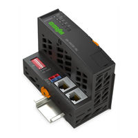
FC ETHERNET G3 XTR Fieldbus Coupler ETHERNET; 3rd Generation; Extreme
Brand:
WAGO
| Category:
I/O Systems
| Size: 9 MB
Table of Contents
Table of Contents
3
Validity of this Documentation
10
Copyright
10
Notes about this Documentation
10
Symbols
11
Number Notation
12
Font Conventions
12
Table 1: Number Notation
12
Table 2: Font Conventions
12
Personnel Qualifications
13
Use of the 750 Series in Compliance with Underlying Provisions
13
Legal Bases
13
Subject to Changes
13
Important Notes
13
Technical Condition of Specified Devices
14
Disposal
14
2.1.4.1.1 Electrical and Electronic Equipment
14
2.1.4.1.2 Packaging
15
Safety Advice (Precautions)
16
Special Use Conditions for ETHERNET Devices
19
System Description
20
Figure 1: Fieldbus Node (Example)
20
Manufacturing Number
21
Hardware Address (MAC ID)
21
Figure 2: Marking Area for Serial Numbers
21
Update
22
Figure 3: Update Matrix up to 2015
22
Figure 4: Update Matrix from 2016
22
Table 3: Legend for Figure "Update Matrix from 2016
22
Assembly Guidelines/Standards
23
Storage, Assembly and Transport
23
Power Supply
24
Overcurrent Protection
24
Isolation
25
Figure 5: Isolation (Example)
25
System Supply
26
Connection
26
Figure 6: System Supply (Example)
26
Table 4: Legend for the "System Supply" Figure
26
Table 5: Alignment
27
Figure 7: System Voltage (Example)
27
Dimensioning
27
Field Supply
30
Connection
30
Figure 8: Field Supply (Sensor/Actuator) (Example)
30
Table 6: Legend for the "Field Supply (Sensor/Actuator)" Figure
30
Fusing Via Power Supply Module
32
Figure 9: Supply Module with Fuse Carrier (Example 750-610/040-000)
32
Table 7: Power Supply Modules
32
Figure 11: Opening the Fuse Carrier and Changing the Fuse
33
Figure 10: Removing the Fuse Carrier
33
Fusing External
34
Figure 12: Changing the Fuse and Closing the Fuse Carrier
34
Figure 13: Push Back the Fuse Carrier
34
Figure 14: Fuse Modules for Automotive Fuses, Series 282
35
Figure 15: Fuse Modules for Automotive Fuses, Series 2006
35
Figure 16: Fuse Modules with Pivotable Fuse Carrier, Series 281
35
Figure 17: Fuse Modules with Pivotable Fuse Carrier, Series 2002
35
Supplementary Power Supply Regulations
36
Table 8: Filter Modules for 24 V Power Supply
36
Figure 18: Power Supply Concept
37
Supply Example
38
Figure 19: Supply Example
38
Table 9: Legend for the "Supply Example" Figure
39
Power Supply Units
40
Grounding
41
Grounding the DIN Rail
41
Framework Assembly
41
Insulated Assembly
41
Table 10: WAGO Ground Wire Terminals
41
Grounding Function
42
Figure 20: Carrier Rail Contact (Example)
42
Shielding
43
General
43
Fieldbus Cables
43
Figure 21: Cable Shield at Ground Potential
43
Shielded Signal Lines
44
WAGO Shield Connecting System
44
Figure 22: Examples of the WAGO Shield Connecting System
44
Figure 23: Application of the WAGO Shield Connecting System
44
Device Description
45
View
47
Figure 24: View
47
Table 11: Legend for Figure "View
48
Connectors
49
Device Supply
49
Figure 25: Device Supply
49
Fieldbus Connection
50
Figure 26: RJ-45 Connector
50
Table 12: RJ-45 Connector and RJ-45 Connector Configuration
50
Table 14: Display Elements Node Status
51
Table 13: Display Elements Fieldbus Status
51
Display Elements
51
Figure 27: Display Elements
51
Operating Elements
52
Service Interface
52
Figure 28: Service Interface (Closed and Opened Flap)
52
Table 15: Legend for Figure "Service Interface (Closed and Opened Flap)
52
Address Selection Switch
53
Figure 29: Address Selection Switch (for Example Setting "0")
53
Table 16: Technical Data - Device
54
Table 17: Technical Data - System
54
Device Data
54
System Data
54
Technical Data
54
Supply
55
Fieldbus MODBUS/TCP
55
Table 22: Technical Data - Climatic Environmental Conditions
56
Table 21: Technical Data - Mechanical Conditions
56
Table 20: Technical Data - Data Contacts
56
Table 19: Technical Data - Wiring Interface
56
Table 18: Technical Data - Accessories
56
Climatic Environmental Conditions
56
Mechanical Conditions
56
Connection Technology
56
Accessories
56
Approvals
57
Standards and Guidelines
58
Table 23: Standards and Rated Conditions for Explosion Protection
58
Table 24: Climatic and Mechanical Environmental Conditions and
59
Table 25: EMC - Immunity to Interference
60
Table 26: EMC - Emission of Interference
62
Table 27: EMC - Emission of Interference - Telecommunication
63
Table 28: Standards and Rated Conditions for Rail Applications
64
Mounting
65
Installation Position
65
Figure 30: Mounting Positions
66
Overall Configuration
67
Mounting Onto Carrier Rail
68
Carrier Rail Properties
68
Table 29: WAGO DIN Rails
69
Spacing
69
WAGO DIN Rails
69
Figure 31: Spacing
69
Mounting Sequence
70
Inserting and Removing Devices
71
Inserting the Fieldbus Coupler/Controller
71
Figure 32: Release Tab of Extended ECO Fieldbus Coupler (Example)
71
Removing the Fieldbus Coupler/Controller
72
Inserting the I/O Module
72
Figure 33: Insert I/O Module (Example)
72
Figure 35: Removing the I/O Module (Example)
73
Removing the I/O Module
73
Figure 34: Snap the I/O Module into Place (Example)
73
Connect Devices
74
Data Contacts/Local Bus
74
Figure 36: Data Contacts
74
Power Contacts/Field Supply
75
Figure 37: Example for the Arrangement of Power Contacts
75
Connecting a Conductor to the CAGE CLAMP
76
Figure 38: Connecting a Conductor to a CAGE CLAMP
76
Figure 39: Operating System
77
Operating System
77
Function Description
77
Process Data Architecture
78
Basic Structure
78
Process Data Ethernet/Ip
79
Data Exchange
80
Addressing
81
Addressing of I/O Modules
81
Figure 40: Memory Areas and Data Exchange
81
Table 30: Data Width for I/O Modules
82
Data Exchange between MODBUS/TCP Master and I/O Modules
82
Figure 41: Data Exchange between MODBUS Master and I/O Modules
83
Table 31: Allocation of Digital Inputs and Outputs to Process Data Words in
83
Data Exchange between Ethernet/Ip Master and I/O Modules
84
Commissioning
85
Connecting Client PC and Fieldbus Nodes
86
Assigning the IP Address to the Fieldbus Node
86
Assigning IP Address Via Address Selection Switch
86
Figure 42: Address Selection Switch, for Example the Value Setting "50
88
Assigning IP Address Via DHCP
88
Enable DHCP
89
Assigning the IP Address Permanently by Option "Use IP from EEPROM
89
Assigning IP Address Via "WAGO Ethernet Settings
91
Assigning the IP Address Via Bootp
92
Note MAC ID
93
Determining IP Addresses
94
Assigning the IP Address Permanently by Option "Use IP from EEPROM
95
Reasons for Failed IP Address Assignment
97
Testing the Function of the Fieldbus Node
98
Preparing the Flash File System
99
Setting Date and Time
101
Restoring Factory Settings
103
Configuring Via the Web-Based Management System (WBM)
104
Table 32: WBM User Groups
104
Information
106
Figure 43: WBM Page "Information" (Example)
106
Table 33: WBM Page "Information
107
Ethernet
108
Figure 44: WBM Page "Ethernet
109
Table 34: WBM Page "Ethernet
110
Tcp/Ip
112
Figure 45: WBM Page "TCP/IP
112
Table 35: WBM Page "TCP/IP
113
Port
114
Figure 46: WBM Page "Port
114
Table 36: WBM Page "Port
115
Snmp
116
SNMP V1/V2C
117
Table 37: WBM Page "SNMP
117
Table 38: WBM Page "SNMP V3
118
Snmp V3
118
Figure 47: WBM Page "Watchdog
119
Watchdog
119
Table 39: WBM Page "Watchdog
120
Security
121
Figure 48: WBM Page "Security
122
Table 40: WBM Page "Security
123
Modbus
124
Figure 49: WBM Page "Modbus
124
Table 41: WBM Page "Modbus
125
Table 42: WBM Page "Features
126
Features
126
Figure 50: WBM Page "Features
126
I/O Config
127
Figure 51: WBM Page "IO Configuration
127
Table 43: WBM Page "I/O Config
127
Diagnostics
128
LED Signaling
128
Figure 52: Display Elements
128
Table 44: LED Assignment for Diagnostics
128
Evaluating Fieldbus Status
129
Table 45: Fieldbus Diagnostics - Solution in Event of Error
129
Evaluating Node Status - I/O LED (Blink Code Table)
130
Table 46: Node Status Diagnostics - Solution in Event of Error
130
Figure 53: Node Status - I/O LED Signaling
131
Figure 54: Error Message Coding
131
Table 47: Blink Code Table for the 'I/O' LED Signaling, Error Code 1
132
Table 48: Blink Code Table for the 'I/O' LED Signaling, Error Code 2
133
Table 49: Blink Code Table for the 'I/O' LED Signaling, Error Code 3
134
Table 50: Blink Code Table for the 'I/O' LED Signaling, Error Code 4
135
Table 51: Blink Code Table for the 'I/O' LED Signaling, Error Code 5
135
Table 52: Blink Code- Table for the I/O LED Signaling, Error Code 6
136
Fault Behavior
137
Fieldbus Failure
137
Local Bus Failure
137
Fieldbus Communication
138
Implemented Protocols
138
Communication Protocols
138
IP (Internet Protocol)
138
Table 53: IP Packet
138
Table 56: Network Class C
139
Table 55: Network Class B
139
Table 54: Network Class a
139
Table 57: Key Data Class A, B and C
140
Table 58: Example: Class B Address with Field for Subnet Ids
141
Table 59: Subnet Mask for Class a Network
141
Table 60: Subnet Mask for Class B Network
141
Table 61: Subnet Mask for Class C Network
141
Table 62: Example for an IP Address from a Class B Network
141
TCP (Transmission Control Protocol)
143
UDP (User Datagram Protocol)
143
Configuration and Diagnostics Protocols
144
Bootp (Bootstrap Protocol)
144
DHCP (Dynamic Host Configuration Protocol)
145
Table 63: Bootp Options
145
Table 64: Meaning of DHCP Options
147
HTTP (Hypertext Transfer Protocol)
148
DNS (Domain Name Systems)
148
FTP-Server (File Transfer Protocol)
148
SNMP (Simple Network Management Protocol)
149
Table 66: Standard Traps
150
Table 65: MIB II Groups
150
11.1.2.6.2 Traps
150
11.1.2.6.1 MIB II Description
150
Application Protocols
151
Modbus Functions
152
General
152
Table 67: Modbus TCP Header
152
Table 68: Basic Data Types of MODBUS Protocol
153
Table 69: List of the MODBUS Functions in the Fieldbus Coupler
153
Use of the MODBUS Functions
154
Figure 55: Use of the MODBUS Functions
154
Description of the MODBUS Functions
155
Table 70: Exception Codes
155
Function Code FC1 (Read Coils)
156
Table 71: Request of Function Code FC1
156
Table 72: Response of Function Code FC1
156
Function Code FC2 (Read Discrete Inputs)
157
Table 73: Assignment of Inputs
157
Table 74: Exception of Function Code FC1
157
Table 75: Request of Function Code FC2
157
Table 78: Exception of Function Code FC2
158
Table 77: Assignment of Inputs
158
Table 76: Response of Function Code FC2
158
Table 81: Exception of Function Code FC3
159
Function Code FC3 (Read Multiple Registers)
159
Table 80: Response of Function Code FC3
159
Table 79: Request of Function Code FC3
159
Function Code FC4 (Read Input Registers)
160
Table 82: Request of Function Code FC4
160
Table 83: Response of Function Code FC4
160
Table 84: Exception of Function Code FC4
160
Table 85: Request of Function Code FC5
161
Table 86: Response of Function Code FC5
161
Table 87: Exception of Function Code FC5
161
Function Code FC5 (Write Coil)
161
Function Code FC6 (Write Single Register)
162
Table 88: Request of Function Code FC6
162
Table 89: Response of Function Code FC6
162
Table 90: Exception of Function Code FC6
162
Table 92: Response of Function Code FC11
163
Table 93: Exception of Function Code FC 11
163
Function Code FC11 (Get Comm Event Counter)
163
Table 91: Request of Function Code FC11
163
Function Code FC15 (Write Multiple Coils)
164
Table 94: Request of Function Code FC15
164
Table 95: Response of Function Code FC15
164
Function Code FC16 (Write Multiple Registers)
165
Table 96: Exception of Function Code FC15
165
Table 97: Request of Function Code FC16
165
Table 98: Response of Function Code FC16
165
Table 101: Response of Function Code FC22
166
Table 102: Exception of Function Code FC22
166
Table 99: Exception of Function Code FC16
166
Table 100: Request of Function Code FC22
166
Function Code FC22 (Mask Write Register)
166
Function Code FC23 (Read/Write Multiple Registers)
167
Table 103: Request of Function Code FC23
167
Table 104: Response of Function Code FC23
167
Table 105: Exception of Function Code FC23
167
MODBUS Register Mapping
168
Table 106: Register Access Reading (with FC3 and FC4)
168
Table 107: Register Access Writing (with FC6 and FC16)
169
Table 109: Bit Access Writing (with FC5 and FC15)
170
Table 108: Bit Access Reading (with FC1 and FC2)
170
MODBUS Registers
171
Table 110: MODBUS Registers
171
Accessing Register Values
172
Watchdog Registers
172
Table 111: MODBUS Registers (Continuation)
172
Modbus Watchdog Register
173
Table 112: Register Address 0X1000
173
Table 113: Register Address 0X1001
173
Table 114: Register Address 0X1002
174
Table 115: Register Address 0X1003
174
Table 116: Register Address 0X1004
174
Table 117: Register Address 0X1005
174
Table 118: Register Address 0X1006
175
Table 119: Register Address 0X1007
175
Table 120: Register Address 0X1008
175
Table 121: Register Address 0X1009
175
Table 122: Register Address 0X100A
175
Table 124: Register Address 0X100B
176
Table 123: Starting Watchdog
176
Diagnostic Registers
177
Table 125: Register Address 0X1020
177
Table 126: Register Address 0X1021
177
Table 129: Register Address 0X1024
178
Table 130: Register Address 0X1025
178
Table 131: Register Address 0X1028
178
Table 128: Register Address 0X1023
178
Table 127: Register Address 0X1022
178
Configuration Registers
178
Table 132: Register Address 0X1029
179
Table 133: Register Address 0X102A
179
Table 134: Register Address 0X102B
179
Table 135: Register Address 0X1030
179
Table 136: Register Address 0X1031
179
Table 137: Register Address 0X1037
180
Table 138: Register Address 0X1050
180
Table 139: Register Address 0X2030
180
Table 142: Register Address 0X2033
181
Table 143: Register Address 0X2040
181
Table 141: Register Address 0X2032
181
Table 140: Register Address 0X2031
181
Table 144: Register Address 0X2041
182
Table 145: Register Address 0X2042
182
Table 146: Register Address 0X2043
182
Firmware Information Registers
183
Table 147: Register Address 0X2010
183
Table 148: Register Address 0X2011
183
Table 150: Register Address 0X2013
183
Table 151: Register Address 0X2014
183
Table 152: Register Address 0X2020
183
Table 149: Register Address 0X2012
183
Table 153: Register Address 0X2021
184
Table 154: Register Address 0X2022
184
Table 155: Register Address 0X2023
184
Table 159: Register Address 0X2003
185
Table 161: Register Address 0X2005
185
Table 160: Register Address 0X2004
185
Table 158: Register Address 0X2002
185
Table 157: Register Address 0X2001
185
Table 156: Register Address 0X2000
185
Constant Registers
185
Table 162: Register Address 0X2006
186
Table 163: Register Address 0X2007
186
Table 164: Register Address 0X2008
186
Ethernet/Ip (Ethernet/Industrial Protocol)
187
General
187
Protocol Overview in the OSI Model
188
Table 165: ISO/OSI Reference Model
188
Characteristics of the Ethernet/Ip Protocol Software
189
EDS File
189
Object Model
190
General
190
Class Overview
191
Table 166: CIP Common Class
191
Table 167: WAGO Specific Classes
191
Explanation of the Table Headings in the Object Descriptions
192
Identity (01 )
192
Hex
192
Table 168: Explanation of the Table Headings in the Object Descriptions
192
Table 169: Identity
193
Table 170: Identity
194
Message Router
195
Table 172: Message Router
195
Hex )
195
Table 171: Identity
195
Table 174: Message Router
196
Assembly Object
196
Table 173: Message Router
196
Hex )
196
Table 175: Static Assembly Instances - Overview
197
Table 176: Assembly
197
Table 177: Static Assembly Instances - Instance
197
Table 178: Static Assembly Instances - Instance
197
Table 179: Static Assembly Instances - Instance
197
Table 180: Static Assembly Instances - Instance
198
Table 181: Static Assembly Instances - Instance
198
Table 182: Static Assembly Instances - Instance
198
Table 183: Static Assembly Instances - Instance
198
Table 184: Static Assembly Instances - Instance
199
Table 185: Static Assembly Instances - Instance
199
Port Class
200
Table 186: Static Assembly Instances - Common Service
200
Hex )
200
Connection Manager
200
Connection
200
Table 187: Port Class
201
Table 188: Port Class
201
Table 189: Port Class
201
TCP/IP Interface
202
Hex
202
Table 190: TCP/IP Interface
202
Ethernet Link
203
Hex )
203
Table 191: TCP/IP Interface
203
Table 192: TCP/IP Interface
203
Table 193: Ethernet Link
204
Table 194: Ethernet Link
205
Table 195: Ethernet Link
207
Table 196: Ethernet Link
209
Table 197: Ethernet Link
209
Coupler/Controller Configuration
209
Hex
209
Table 198: Coupler/Controller Configuration
210
Table 199: Coupler/Controller Configuration
210
Table 200: Coupler/Controller Configuration
211
Table 201: Discrete Input Point
211
Table 202: Discrete Input Point
211
Table 203: Discrete Input Point
211
Table 205: Discrete Output Point
212
Table 207: Discrete Input Point Extended 2 (6D Hex) - Class
212
Table 206: Discrete Input Point Extended
212
Hex )
212
Table 204: Discrete Input Point Extended 1(69 Hex,) - Class
212
Discrete Input Point Extended
212
Discrete Input Point Extended 2 (6D )
212
Table 210: Discrete Input Point Extended 3 (71 Hex) - Class
213
Table 211: Discrete Input Point Extended
213
Table 212: Discrete Input Point Extended
213
Table 209: Analog Input Point
213
Hex )
213
Table 208: Analog Input Point
213
Discrete Output Point
214
Hex )
214
Discrete Output Point Extended 1 (6A )
214
Table 213: Discrete Output Point (66 Hex) - Class
214
Table 214: Discrete Output Point
214
Table 215: Discrete Output Point
214
Table 216: Discrete Output Point Extended
214
Table 220: Discrete Output Point Extended
215
Table 221: Discrete Output Point Extended
215
Table 217: Discrete Output Point Extended
215
Table 219: Discrete Output Point Extended
215
Table 218: Discrete Output Point Extended
215
Discrete Output Point Extended 2 (6E )
215
Hex )
216
Analog Input Point
216
Table 222: Discrete Output Point Extended
216
Table 223: Discrete Output Point Extended
216
Table 224: Discrete Output Point Extended
216
Table 225: Analog Input Point
216
Table 229: Analog Input Point Extended
217
Table 228: Analog Input Point Extended
217
Table 227: Analog Input Point
217
Table 226: Analog Input Point
217
Analog Input Point Extended 1 (6B )
217
Analog Input Point Extended
218
Table 230: Analog Input Point Extended
218
Table 231: Analog Input Point Extended
218
Table 232: Analog Input Point Extended
218
Table 233: Analog Input Point Extended
218
Analog Input Point Extended 2 (6F )
218
Analog Output Point
219
Hex
219
Table 234: Analog Input Point Extended
219
Table 235: Analog Input Point Extended
219
Table 236: Analog Input Point Extended
219
Table 237: Analog Output Point
219
Table 238: Analog Output Point
219
Table 239: Analog Output Point
219
Table 241: Analog Output Point Extended
220
Table 242: Analog Output Point Extended
220
Table 240: Analog Output Point Extended
220
Analog Output Point Extended
220
Analog Output Point Extended 1 (6C )
220
Hex )
221
Table 243: Analog Output Point Extended
221
Table 244: Analog Output Point Extended
221
Table 245: Analog Output Point Extended
221
Table 246: Analog Output Point Extended
221
Table 250: Module Configuration
222
Table 249: Module Configuration
222
Table 248: Analog Output Point Extended
222
Table 247: Analog Output Point Extended
222
Hex )
222
Module Configuration
222
Module Configuration Extended
223
Hex )
223
Table 251: Module Configuration
223
Table 252: Module Configuration Extended
223
Table 253: Module Configuration Extended
223
Table 254: Module Configuration Extended
223
O Modules
224
Overview
224
Process Data Architecture for Modbus-TCP
225
Digital Input Modules
226
Table 257: 16-Channel Digital Input Modules
226
2-Channel Digital Input Modules
226
Table 256: 8-Channel Digital Input Modules
226
Table 255: 2-Channel Digital Input Modules
226
Table 258: 2-Channel Digital Output Modules
227
Table 259: 2-Channel Digital Output Modules with Diagnostics and Input
227
Table 260: 4-Channel Digital Output Modules
227
2-Channel Digital Output Modules with Diagnostics and Input Data
227
2-Channel Digital Output Modules
227
Digital Output Modules
227
8-Channel Digital Output Modules
228
Table 262: 8-Channel Digital Output Modules
228
Table 263: 8-Channel Digital Output Modules with Diagnostics and Input
228
Table 261: 4-Channel Digital Output Modules with Diagnostics and Input
228
16-Channel Digital Output Modules
229
Analog Input Modules
229
2-Channel Analog Input Modules
229
Table 264: 16-Channel Digital Output Modules
229
Table 265: 2-Channel Analog Input Modules
229
Table 267: 3-Phase Power Measurement Module
230
4-Channel Analog Input Modules
230
Table 266: 4-Channel Analog Input Modules
230
3-Phase Power Measurement Module
230
Analog Output Modules
231
Channel Analog Output Modules
231
Table 268: 2 Channel Analog Output Modules
231
Table 269: 4 Channel Analog Output Modules
231
Specialty Modules
232
Serial Interfaces with Alternative Data Format
232
Table 270: Serial Interfaces with Alternative Data Format
232
Table 271: SSI Transmitter Interface Modules with Alternative Data Format
233
Table 272: Incremental Encoder Interface
233
SSI Transmitter Interface I/O Modules
233
Counter Modules
233
Distance and Angle Measurement
233
Table 273: Counter Modules
234
Table 274: Counter Module, Operating Mode "2 up Counter/16 Bit / 5 Khz
234
CAN Gateway
235
Table 275: CAN Gateway
235
Table 277: Supply Modules with Fuse Carrier and Diagnostics
236
System Modules
236
Table 276: Intrinsically Safe Supply Modules with Diagnostics
236
System Modules with Diagnostics
236
Process Data Architecture for Ethernet/Ip
237
1-Channel Digital Input Modules with Diagnostics
238
2-Channel Digital Input Modules
238
Table 278: 1-Channel Digital Input Modules with Diagnostics
238
Table 279: 2-Channel Digital Input Modules
238
Table 280: 2-Channel Digital Input Modules with Diagnostics
238
Digital Input Modules
238
2-Channel Digital Input Modules with Diagnostics and Output Data
239
4-Channel Digital Input Modules
239
Table 281: 2-Channel Digital Input Modules with Diagnostics and Output Data
239
Table 282: 4-Channel Digital Input Modules
239
Table 283: 8-Channel Digital Input Modules
239
Table 284: 16-Channel Digital Input Modules
239
Table 285: 1-Channel Digital Output Modules with Input Data
240
Table 286: 2-Channel Digital Output Modules
240
2-Channel Digital Output Modules
240
1-Channel Digital Output Modules with Input Data
240
Digital Output Modules
240
Table 288: 4-Channel Digital Output Modules
241
Table 289: 4-Channel Digital Output Modules with Diagnostics and Input Data
241
2-Channel Digital Output Modules with Diagnostics and Input Data
241
Table 287: 2-Channel Digital Output Modules with Diagnostics and Input Data
241
4-Channel Digital Output Modules
241
8-Channel Digital Output Modules
242
8-Channel Digital Output Modules with Diagnostics and Input Data
242
Table 291: 8-Channel Digital Output Modules with Diagnostics and Input Data
242
Table 292: 16-Channel Digital Output Modules
242
Table 290: 8-Channel Digital Output Modules
242
8-Channel Digital Input/Output Modules
243
Analog Input Modules
243
Table 293: 8-Channel Digital Input/Output Modules
243
1-Channel Analog Input Modules
244
Table 294: 1-Channel Analog Input Modules
244
Table 295: 2-Channel Analog Input Modules
244
Table 296: 4-Channel Analog Input Modules
244
Table 297: 2-Channel Analog Output Modules
245
Table 298: 4-Channel Analog Output Modules
245
2-Channel Analog Output Modules
245
Analog Output Modules
245
Specialty Modules
246
Serial Interfaces with Alternative Data Format
246
Table 299: Serial Interfaces with Alternative Data Format
246
SSI Transmitter Interface I/O Modules
247
Distance and Angle Measurement
247
Table 300: SSI Transmitter Interface Modules with Alternative Data Format
247
Table 301: Incremental Encoder Interface I/O Module
247
Table 302: Binary Space Module (with Behavior Like 2 Channel Digital Input)
248
System Modules
248
Binary Space Module
248
Application Examples
249
Test of Modbus Protocol and Fieldbus Nodes
249
Visualization and Control Using SCADA Software
249
Figure 56: Example SCADA Software with Modbus Driver
251
Table 303: Modbus Table and Function Codes
251
Use in Hazardous Environments
252
Figure 58: Text Detail - Marking Example According to ATEX and Iecex
253
Figure 57: Marking Example According to ATEX and Iecex
253
Marking for Europe According to ATEX and Iecex
253
Marking Configuration Examples
253
Table 304: Description of Marking Example According to ATEX and Iecex
254
Figure 59: Marking Example for Approved Ex I I/O Module According to
255
Figure 60: Text Detail - Marking Example for Approved Ex I I/O Module
255
Table 305: Description of Marking Example for Approved Ex I I/O Module According to ATEX and Iecex
256
Table 307: Description of Marking Example for Approved Ex I I/O Module
256
Figure 62: Text Detail - Marking Example According to NEC 500
257
Table 306: Description of Marking Example According to NEC 500
257
Figure 61: Marking Example According to NEC
257
Marking for the United States of America (NEC) and Canada (CEC)
257
Figure 63: Text Detail - Marking Example for Approved Ex I I/O Module
258
Figure 64: Text Detail - Marking Example for Approved Ex I I/O Module
258
Table 308: Description of Marking Example for Approved Ex I I/O Modules
258
Figure 65: Text Detail - Marking Example for Approved Ex I I/O Modules
259
Table 309: Description of Marking Example for Approved Ex I I/O Modules
259
Installation Regulations
260
Special Notes Including Explosion Protection
260
Special Notes Regarding ANSI/ISA Ex
262
Advertisement
WAGO WAGO-I/O-SYSTEM 750 XTR Series Manual (108 pages)
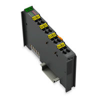
4PWM 24 VDC 0.2A XTR 4 Pulse Width Outputs; 24 VDC; 0.2 A; 20 kHz; Extreme
Brand:
WAGO
| Category:
I/O Systems
| Size: 4 MB
Table of Contents
Table of Contents
3
Copyright
6
Notes about this Documentation
6
Validity of this Documentation
6
Symbols
7
Number Notation
9
Font Conventions
9
Table 1: Number Notation
9
Table 2: Font Conventions
9
Personnel Qualifications
10
Use of the 750 Series in Compliance with Underlying Provisions
10
Subject to Changes
10
Legal Bases
10
Important Notes
10
Technical Condition of Specified Devices
11
2.1.4.1.1 Electrical and Electronic Equipment
11
Disposal
11
2.1.4.1.2 Packaging
12
Safety Advice (Precautions)
13
Device Description
17
View
19
Figure 1: View
19
Table 3: Legend for Figure "View
19
Connectors
20
Data Contacts/Local Bus
20
Figure 2: Data Contacts
20
Table 4: Legend for Figure "Power Jumper Contacts
21
Power Jumper Contacts/Field Supply
21
Figure 3: Power Jumper Contacts
21
Cage Clamp
22
Figure 4: CAGE CLAMP ® Connectors
22
Table 5: Legend for Figure "CAGE CLAMP ® Connectors
22
Display Elements
24
Figure 5: Display Elements
24
Table 6: Legend for Figure "Display Elements
24
Schematic Diagram
25
Figure 6: Schematic Diagram
25
Table 8: Technical Data - Power Supply
26
Table 7: Technical Data - Device
26
Power Supply
26
Device Data
26
Technical Data
26
Table 9: Technical Data − Outputs
27
Connection Type
28
Mechanical Conditions
28
Climatic Environmental Conditions
28
Table 10: Technical Data - Field Wiring
28
Table 11: Technical Data - Power Jumper Contacts
28
Table 12: Technical Data - Data Contacts
28
Table 13: Technical Data - Mechanical Conditions
28
Table 14: Technical Data - Climatic Environmental Conditions
28
Approvals
29
Table 15: Standards and Rated Conditions for Explosion Protection Applications
31
Standards and Guidelines
31
Table 16: Climatic and Mechanical Environmental Conditions and
32
Table 17: EMC - Product- and Generic Standards
33
Table 18: EMC - Testing Standards: Immunity to Interference
34
Table 19: Emc - Testing Standards: Emission of Interference
36
Table 20: Standards and Rated Conditions for Rail Applications
38
Table 21: Further EMC Requirements for Railroad Applications
38
Notes and Limitations on Areas of Application
39
Power Plants and Voltage Substations
39
Residential Applications
39
Figure 7: Diagram for Determining the Cable Length in Residential
39
Figure 8: Diagram for Determining the Max. Cable Lengths in Marine
40
Marine Applications
40
Table 22: WAGO Power Supplies for Field Supply in Marine Applications
41
Process Image
42
Operating Modes
43
Pwm DC
43
Process Image
44
Table 23: Process Image (PWM DC)
44
Table 24: Control Byte 0 (PWM DC)
44
Table 25: Control Byte 2 (PWM DC)
44
Parameter Settings
45
Function of the Output Channels
45
Table 26: Status Byte 0 (PWM DC)
45
Table 27: Status Byte 2 (PWM DC)
45
Table 28: Process Values (PWM DC)
46
Process Values
46
PWM Frq
47
Process Image
47
Table 29: Process Image (PWM Frq)
47
Table 30: Control Byte 0 (PWM Frq)
47
Table 31: Control Byte 2 (PWM Frq)
48
Table 32: Status Byte 0 (PWM Frq)
48
Table 33: Status Byte 2 (PWM Frq)
48
Parameter Settings
49
Function of the Output Channels
49
Process Values
49
Table 34: Process Values (PWM Frq)
49
Table 35: Process Image (PWM Frq-Cnt)
50
Process Image
50
PWM Frq-Cnt
50
Table 36: Control Byte 0 (PWM Frq-Cnt)
51
Table 37: Control Byte 2 (PWM Frq-Cnt)
51
Parameter Settings
52
Table 38: Status Byte 0 (PWM Frq-Cnt)
52
Table 39: Status Byte 2 (PWM Frq-Cnt)
52
Function of the Output Channels
53
Process Values (PWM Frq-Cnt)
53
Table 40: Process Values (PWM Frq-Cnt)
53
Pulse Frq-Cnt
54
Process Image
54
Table 41: Process Image (Pulse Frq-Cnt)
54
Table 44: Status Byte 0 (Pulse Frq-Cnt)
55
Table 43: Control Byte 2 (Pulse Frq-Cnt)
55
Table 42: Control Byte 0 (Pulse Frq-Cnt)
55
Table 62: Status Byte 0
56
Parameter Settings
56
Table 45: Status Byte 2 (Pulse Frq-Cnt)
56
Function of the Output Channels
57
Process Values (Pulse Frq-Cnt)
57
Table 46: Process Values (Pulse Frq-Cnt)
57
PWM Pulse-Dir
58
Process Image
59
Table 47: Process Image (PWM Pulse-Dir)
59
Table 48: Control Byte 0 (PWM Pulse-Dir)
59
Table 49: Control Byte 2 (PWM Pulse-Dir)
59
Table 51: Status Byte 2 (PWM Pulse-Dir)
60
Table 50: Status Byte 0 (PWM Pulse-Dir)
60
Function of the Output Channels
61
Process Values
61
Table 63: Status Byte 2
61
Parameter Settings
61
Table 52: Process Values (PWM Pulse-Dir)
62
Functions
63
Mounting
64
Mounting Sequence
64
Inserting and Removing Devices
65
Inserting the I/O Module
65
Figure 9: Inserting I/O Module (Example)
65
Figure 11: Removing the I/O Module (Example)
66
Removing the I/O Module
66
Figure 10: Snap the I/O Module into Place (Example)
66
Connecting a Conductor to the CAGE CLAMP
67
Figure 12: Connecting a Conductor to a CAGE CLAMP
67
Connect Devices
67
Connection Examples
68
Figure 13: Connection Example 1
68
Figure 14: Example 2 ─ All Channels with Non-Inverted Configured Output
69
Figure 15: Example 3 ─ All Channels with Inverted Configured Output
69
Figure 16: Example 4 ─ Bridge Mode Channel Pair 1&2 When Wiring the Load
70
Start Via WAGO-I/O-CHECK
71
Figure 17: Starting the Parameterization Dialog from WAGO-I/O-CHECK
71
Configuration and Parameterization with WAGO Software Tools
71
Commissioning
71
Via E!Cockpit Starten
72
Figure 18: Scan Nodes (Example)
72
Figure 19: Apply the Network View (Example)
73
Figure 20: Open Device View (Example)
73
Figure 21: Module Settings (Example)
73
Parameterization Dialog
74
Figure 23: Parameterization Dialog
74
Table 53: Legend for Figure "Parameterization Dialog
74
General Settings
75
Table 54: Buttons
75
Table 55: Navigation Via the Menu
75
Table 56: 750-677, "Common" Menu Item
76
Figure 24: 750-677, "General" Menu Item
76
Settings of the Channel Pairs
76
Table 57: 750-677, "Channel X & Y" Menu Item
77
Figure 25: 750-677, "Channels X & Y" Menu Item, Selecting the Operating
79
Figure 26: 750-677, "Channels X & Y" Menu Item, Selecting the Operating
80
Figure 27: 750-677, "Channels X & Y" Menu Item, Selecting the Operating
80
Figure 28: 750-677, "Channels X & Y" Menu Item, Selecting the Operating Mode (Example 4)
80
IO Test
81
Data Dialog
81
Figure 30: Data Dialog (Sample Excerpt)
81
Table 58: Data Dialog Legend
81
Figure 31: Data Dialog, Example 1
82
Figure 32: Data Dialog, Example 2
83
Figure 34: Context Menu
84
Figure 33: Data Dialog, Example 3
84
Figure 35: Data Dialog, Example 4
85
Configuration and Parameterization Via GSD File
86
Configuration 750-677/040-000 (4PWM 24 VDC 0.2A XTR)
86
Fieldbus Coupler PROFIBUS DP 750-333/040-000
86
Parameterization 750-677/040-000 (4PWM 24 VDC 0.2A XTR)
86
Table 59: PROFIBUS DP Configuration
86
Table 60: Device-Specific Parameters
87
Diagnostics
88
Behavior of the I/O Module in the Event of an Error
88
Diagnostics Via Status Byte
88
Table 61: Prioritization of Status Information
88
Table 66: Signal Evaluation - Channel LED "C
89
Table 67: Signal Evaluation - Channel LED "G
89
Table 64: Signal Evaluation - Status LED "A
89
Table 65: Signal Evaluation - Error LED "E
89
Diagnostics Via Indicators
89
Use in Hazardous Environments
90
Marking Configuration Examples
91
Marking for Europe According to ATEX and Iecex
91
Figure 37: Marking Example Per ATEX and Iecex
91
Figure 38: Text Detail - Marking Example Per ATEX and Iecex
91
Table 68: Description of the Marking Example Per ATEX and Iecex
92
Figure 39: Marking Example of an Approved I/O Module Ex I Per ATEX and Iecex
93
Figure 40: Text Detail - Marking Example of an Approved I/O Module Ex I Per ATEX and Iecex
93
Table 69: Description of the Marking Example of an Approved I/O Module Ex I Per ATEX and Iecex
94
Table 70: Description of Marking Example According to NEC 500
95
Marking for the United States of America (NEC) and Canada (CEC)
95
Table 71: Description of Marking Example for Approved I/O Module Ex I
96
Table 72: Description of Marking Example for Approved I/O Module Ex I
96
Table 73: Description of Marking Example for Approved I/O Module Ex I
97
Installation Regulations
98
Special Notes Including Explosion Protection
98
Special Notes Regarding UL Hazardous Location
100
Service
101
Factory Setting (Default Values)
101
Firmware Update/Downgrade
101
Table 74: Factory Settings - Default Values
101
WAGO WAGO-I/O-SYSTEM 750 XTR Series Manual (94 pages)
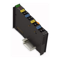
4AI U/I Diff Galv XTR 4-Channel Analog Input; for Voltage/Current; Extreme
Brand:
WAGO
| Category:
I/O Systems
| Size: 4 MB
Table of Contents
Table of Contents
3
Copyrights
5
Notes about this Documentation
5
Validity of this Documentation
5
Copyright
7
Symbols
8
Number Notation
10
Font Conventions
10
Table 1: Number Notation
10
Table 2: Font Conventions
10
Use of the 750 Series in Compliance with Underlying Provisions
11
Personnel Qualifications
11
Subject to Changes
11
Legal Bases
11
Important Notes
11
Technical Condition of Specified Devices
12
Disposal
12
2.1.4.1.1 Electrical and Electronic Equipment
12
2.1.4.1.2 Packaging
13
Safety Advice (Precautions)
14
Device Description
18
Table 3: Compatibility List 750-471/040-000
19
View
21
Figure 1: View
21
Table 4: Legend for Figure "View
21
Connectors
22
Data Contacts/Local Bus
22
Figure 2: Data Contacts
22
Power Jumper Contacts/Field Supply
23
Figure 3: Power Jumper Contacts
23
Table 5: Legend for Figure "Power Jumper Contacts
23
Table 6: Legend for Figure "CAGE CLAMP ® Connectors
24
Figure 4: CAGE CLAMP ® Connectors
24
CAGE CLAMP ® Connectors
24
Display Elements
25
Figure 5: Display Elements
25
Table 7: Legend for Figure "Display Elements
25
Schematic Diagram
27
Figure 6: Schematic Diagram
27
Figure 7: Circuit Diagram
27
Table 8: Technical Data - Device
28
Table 10: Technical Data - Isolation
28
Table 9: Technical Data - Supply
28
Supply
28
Isolation
28
Technical Data
28
Device Data
28
Inputs
29
Communication
29
Connection Type
29
Table 11: Technical Data - Inputs
29
Table 12: Technical Data - Communication
29
Table 13: Technical Data - Field Wiring
29
Table 16: Technical Data - Mechanical Conditions
30
Table 17: Technical Data - Climatic Environmental Conditions
30
Climatic Environmental Conditions
30
Table 15: Technical Data - Data Contacts
30
Table 14: Technical Data - Power Jumper Contacts
30
Mechanical Conditions
30
Approvals
31
Standards and Guidelines
33
Table 18: Standards and Rated Conditions for Explosion Protection Applications
33
Table 19: Climatic and Mechanical Environmental Conditions and
34
Table 20: EMC - Product- and Generic Standards
35
Table 21: EMC - Testing Standards: Immunity to Interference
36
Table 22: Emc - Testing Standards: Emission of Interference
37
Table 23: Standards and Rated Conditions for Rail Applications
39
Table 24: Further EMC Requirements for Railroad Applications
39
Process Image
40
Overview
40
Table 25: Process Image - I/O Module750-471/040-000
41
Status Bytes
42
Table 26: Status Byte CH1_S0
42
Table 27: Process Data, Signal Types
43
Overview of Sensor Types
43
Process Data
43
Signal Types "0
44
Table 28: Signal Types "0
44
Table 29: Signal Types "0
45
(Default)
46
Signal Types "±10 V", "±200 MV" "±20 Ma", Two's Complement (Default)
46
Table 30: Signal Types "±10 V", "±200 MV", "±20 Ma", Two's Complement
46
Table 31: Signal Types "±10 V", "±200 MV" "±20 Ma", Two's Complement
47
Table 32: Signal Types "±10 V", "±200 MV" "±20 Ma", Amount/Sign Format
47
Table 33: Signal Types "±10 V", "±200 MV" "±20 Ma", Amount/Sign Format
48
Signal Type "Namur NE43
49
Table 34: Signal Type "Namur NE43", Two's Complement
49
Table 35: Signal Type "Namur NE43", Two's Complement with Status
50
Table 36: Signal Type "Namur NE43", Amount/Sign Format
51
Table 37: Signal Type "Namur NE43", Amount/Sign Format with Status
52
Mounting
53
Mounting Sequence
53
Inserting and Removing Devices
54
Inserting the I/O Module
54
Figure 8: Inserting I/O Module (Example)
54
Figure 10: Removing the I/O Module (Example)
55
Figure 9: Snap the I/O Module into Place (Example)
55
Removing the I/O Module
55
Connect Devices
56
Connecting a Conductor to the CAGE CLAMP
56
Figure 11: Connecting a Conductor to a CAGE CLAMP
56
Connection Examples
57
Figure 12: Connection Example 750-471/040-000
57
Commissioning
58
Configuration and Parameterization with WAGO Software Tools
58
Start Via WAGO-I/O-CHECK
58
Figure 13: Starting the Parameterization Dialog from WAGO-I/O-CHECK
58
Figure 14: WAGO-I/O-CHECK User Interface
60
Parameterization Dialog
61
Toolbar on the Configuration Dialog
61
Figure 15: Parameterization Dialog
61
Figure 16: Toolbar
61
Navigation Area
62
Figure 17: Navigation
62
Table 38: Toolbar
62
Common
63
Figure 18: Parameter „Common
63
Table 39: Navigation
63
Table 40: "General" Parameters
64
Channel Settings
65
Figure 19: Parameter „Channel
65
Table 41: Parameter „Channel
65
Scaling
66
Figure 20: Parameter "Scaling
67
Table 42: "Scaling" Parameters
67
Calibration
68
Figure 21: "Calibration" Parameters
69
Table 43: Calibration Parameters
69
Figure 22: Offset Correction
70
Figure 23: Gain Correction
70
Configuration and Parameterization Via GSD File
71
4AI U/I Diff/Galv Configuration
71
PROFIBUS DP Fieldbus Couplers 750-333/040-000
71
Table 44: PROFIBUS DP Configuration
71
4AI U/I Diff/Galv Parameterization
72
Figure 24: Example of the PROFIBUS DP Fieldbus Couplers
72
All PROFIBUS DP and PROFINET IO Fieldbus Couplers/Controllers
73
Table 45: Specific Module/Channel Parameters for 750-471/040-000
73
Table 46: General Module/Channel Parameters
74
PROFIBUS DP Fieldbus Couplers 750-333/040-000
74
Scaling Measured Values
75
Table 47: Variable Legend - Scaling Measured Values
75
Diagnostics
76
I/O Module Behavior in the Event of an Error
76
Table 48: Priority Levels of Diagnostic Functions
76
Table 49: Behavior in the Event of an I/O Module Error Dependent on the
77
Firmware Update
79
Use in Hazardous Environments
80
Figure 26: Text Detail - Marking Example Per ATEX and Iecex
81
Figure 25: Marking Example Per ATEX and Iecex
81
Marking Configuration Examples
81
Marking for Europe According to ATEX and Iecex
81
Table 50: Description of the Marking Example Per ATEX and Iecex
82
Figure 27: Marking Example of an Approved I/O Module Ex I Per ATEX and
83
Figure 28: Text Detail - Marking Example of an Approved I/O Module Ex I
83
Table 51: Description of the Marking Example of an Approved I/O Module Ex I Per ATEX and Iecex
84
Marking for the United States of America (NEC) and Canada (CEC)
85
Figure 29: Marking Example According to NEC
85
Figure 30: Text Detail - Marking Example According to NEC 500
85
Table 52: Description of Marking Example According to NEC 500
85
Table 54: Description of Marking Example for Approved I/O Module Ex I
86
Figure 31: Text Detail - Marking Example for Approved I/O Module Ex I
86
Table 53: Description of Marking Example for Approved I/O Module Ex I
86
Figure 32: Text Detail - Marking Example for Approved I/O Module Ex I
86
Figure 33: Text Detail - Marking Example for Approved I/O Module Ex I
87
Table 55: Description of Marking Example for Approved I/O Module Ex I
87
Installation Regulations
88
Special Notes Including Explosion Protection
88
Special Notes Regarding UL Hazardous Location
90
Advertisement
WAGO WAGO-I/O-SYSTEM 750 XTR Series Manual (76 pages)
Brand:
WAGO
| Category:
I/O Systems
| Size: 6 MB
Table of Contents
Table of Contents
3
1 Notes about this Documentation
5
Validity of this Documentation
5
Copyright
5
Symbols
6
Number Notation
8
Font Conventions
8
Table 1: Number Notation
8
Table 2: Font Conventions
8
2 Important Notes
9
Legal Bases
9
Subject to Changes
9
Personnel Qualifications
9
Use of the 750 Series in Compliance with Underlying Provisions
9
Technical Condition of Specified Devices
10
Disposal
10
2.1.4.1.1 Electrical and Electronic Equipment
10
2.1.4.1.2 Packaging
11
Safety Advice (Precautions)
12
3 System Description
16
Figure 1: Fieldbus Node (Example)
16
Labeling
18
Table 3: Marking Symbols
18
Manufacturing Number
20
Figure 2: Marking Area for Serial Numbers
20
Update
21
Storage, Assembly and Transport
21
Figure 3: Update Matrix up to 2015
21
Figure 4: Update Matrix from 2016
21
Table 4: Legend for Figure "Update Matrix from 2016
21
Assembly Guidelines/Standards
22
Technical Data
23
Mechanics
23
Table 5: Technical Data - Mechanics
23
Electrical Safety
24
Connection Type
24
Table 6: Technical Data - Electrical Safety
24
Table 7: Technical Data - Field Wiring
24
Table 8: Technical Data - Power Jumper Contacts
24
Table 9: Technical Data - Local Bus
24
Climatic Environmental Conditions
25
Table 10: Technical Data - Climatic Environmental Conditions
25
Residential Use
26
Example Dimensions
27
Figure 5: Dimensions - Nodes with Fieldbus Coupler/Controller (Example)
27
4 Standards and Approvals
28
Table 11: Climatic and Mechanical Environmental Conditions
28
Table 12: EMC
29
Table 13: Standards and Rated Conditions for Explosion Protection
30
Table 14: Standards and Rated Conditions for Explosion Protection
30
Table 15: Standards and Rated Conditions for Rail Applications
31
5 Mounting
32
Mounting Position
32
Coordinates Model
32
Overview of Mounting Positions
32
Figure 6: Coordinates Model: Width (X), Height (Y), Depth (Z)
32
Figure 7: Mounting Positions
33
Overall Configuration
34
Mounting Onto Carrier Rail
35
Carrier Rail Properties
35
WAGO DIN Rail
36
Table 16: WAGO DIN Rail
36
Table 17: Permissible WAGO Carrier Rails When Using XTR PFC200 for
36
Spacing
37
Figure 8: Spacing
37
Mounting Sequence
38
Inserting and Removing Devices
40
Inserting the Fieldbus Coupler/Controller
40
Removing the Fieldbus Coupler/Controller
41
Figure 9: Turn the DIN-Rail Locking Cam of the Fieldbus Coupler/Controller
41
Inserting the I/O Module
42
Figure 10: Inserting I/O Module (Example)
42
Figure 11: Snap the I/O Module into Place (Example)
42
Removing the I/O Module
43
Figure 12: Removing the I/O Module (Example)
43
6 Connect Devices
44
Data Contacts/Local Bus
44
Figure 13: Data Contacts
44
Power Contacts/Field Supply
45
Figure 14: Example for the Arrangement of Power Contacts
45
Connecting a Conductor to the CAGE CLAMP
46
Figure 15: Connecting a Conductor to a CAGE CLAMP
46
Connecting a Conductor to the Push-In CAGE CLAMP
47
Figure 16: Connecting a Conductor to a Push-In CAGE CLAMP
47
Power Supply
48
Overcurrent Protection
48
Isolation
49
Figure 17: Isolation for Fieldbus Couplers/Controllers (Example)
49
System Supply
50
Connection
50
Figure 18: System Voltage for Fieldbus Couplers/Controllers (Example)
50
Table 18: Legend for Figure "System Voltage for Fieldbus Couplers
50
Figure 19: System Supply for Fieldbus Coupler/Controller
51
Dimensioning
52
Table 19: Alignment
52
Field Supply
54
Connection
54
Figure 20: Field Supply for Fieldbus Couplers/Controllers (Example)
54
Table 20: Legend for Figure "Field Supply for Fieldbus Couplers/Controllers
54
Fusing Via Power Supply Module
56
Figure 21: Supply Module with Fuse Carrier (Example 750-610/040-000)
56
Table 21: Power Supply Modules
56
Figure 22: Removing the Fuse Carrier
57
Figure 23: Opening the Fuse Carrier and Changing the Fuse
57
Fusing External
58
Figure 24: Changing the Fuse and Closing the Fuse Carrier
58
Figure 25: Push Back the Fuse Carrier
58
Figure 26: Fuse Modules for Automotive Fuses, Series 282
59
Figure 27: Fuse Modules for Automotive Fuses, Series 2006
59
Figure 28: Fuse Modules with Pivotable Fuse Carrier, Series 281
59
Figure 29: Fuse Modules with Pivotable Fuse Carrier, Series 2002
59
Power Supply for Mixed Operation
60
Table 22: XTR Supply Modules for Powering XTR Sections
60
Supplementary Power Supply Regulations
61
Table 23: Filter Modules for 24 V Power Supply
61
Figure 30: Power Supply Concept
62
Table 24: Legende for Figure "Power Supply Concept
62
Supply Example
63
Figure 31: Power Supply Example
63
Table 25: Legend for Figure "Power Supply Example
64
Power Supply Units
65
Grounding
66
Grounding the DIN Rail
66
Framework Assembly
66
Insulated Assembly
66
Table 26: WAGO Ground Wire Terminals
66
Grounding Function
67
Figure 32: Carrier Rail Contact (Example)
67
Shielding
68
General
68
Fieldbus Cables
68
Figure 33: Cable Shield at Ground Potential
68
Shielded Signal Lines
69
WAGO Shield Connecting System
69
Figure 34: Examples of the WAGO Shield Connecting System
69
Figure 35: Application of the WAGO Shield Connecting System
69
Power Supply Concept for XTR Ex I
70
Figure 36: Ex I XTR Power Supply Concept
71
Table 27: Legend for Figure "Ex I XTR Power Supply Concept
71
Supplementary Power Supply Regulations for XTR Ex I
72
Figure 37: Power Supply Concept, Example 1
72
Table 28: Filter Modules for 24V Power Supply
72
Figure 38: Power Supply Concept, Example 2
73
Table 29: Legend for Figure "Power Supply Concept, Example 1
73
Table 30: Legend for Figure "Power Supply Concept, Example 2
73
WAGO WAGO-I/O-SYSTEM 750 XTR Series Manual (56 pages)
Design Notes /XTR Guidelines and Recommendations for Increasing Operational Safety
Brand:
WAGO
| Category:
I/O Systems
| Size: 2 MB
Table of Contents
Deutsch
3
Table of Contents
3
1 Notes about this Documentation
5
Validity of this Documentation
5
Copyright
5
Symbols
6
Number Notation
8
Font Conventions
8
Table 1: Number Notation
8
Table 2: Font Conventions
8
2 Important Notes
9
Legal Bases
9
Subject to Changes
9
Personnel Qualifications
9
Use of the WAGO-I/O-SYSTEM 750 in Compliance with Underlying Provisions
9
Technical Condition of Specified Devices
10
Safety Advice (Precautions)
11
3 System Description
13
Manufacturing Number
15
Component Update
16
Storage, Assembly and Transport
16
Assembly Guidelines/Standards
16
Technical Data
17
Mechanics
17
Electrical Safety
17
Table 3: Technical Data - Mechanics
17
Table 4: Technical Data - Electrical Safety
17
Connection Type
18
Climatic Environmental Conditions
18
Table 5: Technical Data - Field Wiring
18
Table 6: Technical Data - Power Jumper Contacts
18
Table 7: Technical Data - Internal Bus
18
Table 8: Technical Data - Climatic Environmental Conditions
18
Residential Use
19
Example Dimensions
20
4 Standards and Approvals
21
Table 9: Climatic and Mechanical Environmental Conditions
21
Table 10: EMC
22
5 Assembly
23
Mounting Position
23
Overall Configuration
23
Mounting Onto Carrier Rail
24
Carrier Rail Properties
24
WAGO DIN Rail
25
Table 11: WAGO DIN Rail
25
Table 12: Permissible WAGO Carrier Rails When Using XTR PFC200
25
Spacing
26
Mounting Sequence
27
Inserting and Removing Devices
29
Inserting the Fieldbus Coupler/Controller
29
Removing the Fieldbus Coupler/Controller
29
Inserting the I/O Module
30
Removing the I/O Module
31
6 Connect Devices
32
Data Contacts/Internal Bus
32
Power Contacts/Field Supply
33
Connecting a Conductor to the CAGE CLAMP
34
Connecting a Conductor to the Push-In CAGE CLAMP
35
Power Supply
36
Isolation
36
System Supply
37
Connection
37
Table 13: Legend for Figure "System Voltage for Fieldbus Couplers
37
Dimensioning
38
Table 14: Alignment
38
Field Supply
41
Connection
41
Table 15: Legend for Figure "Field Supply for Fieldbus Couplers/Controllers
41
Fusing
42
Power Supply for Mixed Operation
44
Table 16: XTR Supply Modules for Powering XTR Sections
44
Supplementary Power Supply Regulations
45
Table 17: Filter Modules for 24 V Power Supply
45
Supply Example
47
Table 18: Legend for Figure "Power Supply Example
48
Power Supply Units
49
Table 19: WAGO Power Supply Units
49
Grounding
50
Grounding the DIN Rail
50
Framework Assembly
50
Insulated Assembly
50
Table 20: WAGO Ground Wire Terminals
50
Grounding Function
51
Shielding
52
General
52
Bus Cables
52
Signal Lines
53
WAGO Shield Connecting System
53
WAGO WAGO-I/O-SYSTEM 750 XTR Series Manual (60 pages)
8DO 24 VDC 0.5A LSS 2-wire XTR 8-Channel Digital Output; 24 VDC; 0.5 A; Low-Side Switching; 2-Wire Connection; Extreme
Brand:
WAGO
| Category:
I/O Systems
| Size: 3 MB
Table of Contents
Table of Contents
3
Copyright
5
Notes about this Documentation
5
Validity of this Documentation
5
Symbols
6
Number Notation
8
Font Conventions
8
Table 1: Number Notation
8
Table 2: Font Conventions
8
Personnel Qualifications
9
Use of the 750 Series in Compliance with Underlying Provisions
9
Subject to Changes
9
Legal Bases
9
Important Notes
9
Technical Condition of Specified Devices
10
2.1.4.1.1 Electrical and Electronic Equipment
10
Disposal
10
2.1.4.1.2 Packaging
11
Safety Advice (Precautions)
12
Device Description
16
View
18
Figure 1: View 750-1516/040-000
18
Table 3: Legend for Figure "View
18
Connectors
19
Data Contacts/Local Bus
19
Figure 2: Data Contacts
19
Table 4: Legend for Figure "Power Jumper Contacts
20
Power Jumper Contacts/Field Supply
20
Figure 3: Power Jumper Contacts
20
Push-In CAGE CLAMP ® Connectors
22
Figure 4: Push-In CAGE CLAMP ® Connectors
22
Table 5: Legend for Figure "Push-In CAGE CLAMP ® Connectors
22
Display Elements
23
Operating Elements
23
Figure 5: Display Elements
23
Table 6: Legend for Figure "Display Elements
23
Schematic Diagram
24
Figure 6: Schematic Diagram
24
Table 7: Technical Data - Device
25
Connection Type
25
Device Data
25
Technical Data
25
Mechanical Conditions
26
Climatic Environmental Conditions
26
Table 8: Technical Data - Field Wiring
26
Table 9: Technical Data - Power Jumper Contacts
26
Table 10: Technical Data - Data Contacts
26
Table 11: Technical Data - Mechanical Conditions
26
Table 12: Technical Data - Climatic Environmental Conditions
26
Approvals
27
Standards and Guidelines
29
Table 13: Standards and Rated Conditions for Explosion Protection Applications
29
Table 14: Climatic and Mechanical Environmental Conditions and
30
Table 15: EMC - Product- and Generic Standards
31
Table 16: EMC - Testing Standards: Immunity to Interference
32
Table 17: Emc - Testing Standards: Emission of Interference
34
Table 18: Standards and Rated Conditions for Rail Applications
36
Table 19: Further EMC Requirements for Railroad Applications
36
Process Image
37
Table 20: Output Bits
37
Mounting
38
Mounting Sequence
38
Inserting and Removing Devices
39
Inserting the I/O Module
39
Figure 7: Inserting I/O Module (Example)
39
Figure 9: Removing the I/O Module (Example)
40
Figure 8: Snap the I/O Module into Place (Example)
40
Removing the I/O Module
40
Connect Devices
41
Connecting a Conductor to the Push-In CAGE CLAMP
41
Figure 10: Connecting a Conductor to a Push-In CAGE CLAMP
41
Connection Example
42
Figure 11: Connection Example with Two Actuators on Channels 1 and 2
42
Using in Safety Related Applications
43
Important Notes
43
Connection to Safety Switching Devices or F I/O Modules
45
General Structure of a Potential Group
45
Figure 12: Setting up a Potential Group (Example)
45
Table 21: Supply or Filter Modules for Setting up a Potential Group
45
Figure 14: 8-Channel Double-Pole Disconnection (Example)
46
Figure 13: 8-Channel Single-Pole Disconnection (Example)
46
Examples of Connection
46
Use in Hazardous Environments
47
Marking Configuration Examples
48
Marking for Europe According to ATEX and Iecex
48
Figure 15: Marking Example Per ATEX and Iecex
48
Figure 16: Text Detail - Marking Example Per ATEX and Iecex
48
Table 22: Description of the Marking Example Per ATEX and Iecex
49
Figure 17: Marking Example of an Approved I/O Module Ex I Per ATEX and
50
Figure 18: Text Detail - Marking Example of an Approved I/O Module Ex I
50
Table 23: Description of the Marking Example of an Approved I/O Module Ex I Per ATEX and Iecex
51
Table 24: Description of Marking Example According to NEC 500
52
Figure 20: Text Detail - Marking Example According to NEC 500
52
Figure 19: Marking Example According to NEC
52
Marking for the United States of America (NEC) and Canada (CEC)
52
Figure 21: Text Detail - Marking Example for Approved I/O Module Ex I
53
Figure 22: Text Detail - Marking Example for Approved I/O Module Ex I
53
Table 25: Description of Marking Example for Approved I/O Module Ex I
53
Table 26: Description of Marking Example for Approved I/O Module Ex I
53
Figure 23: Text Detail - Marking Example for Approved I/O Module Ex I
54
Table 27: Description of Marking Example for Approved I/O Module Ex I
54
Installation Regulations
55
Special Notes Including Explosion Protection
55
Special Notes Regarding UL Hazardous Location
57
WAGO WAGO-I/O-SYSTEM 750 XTR Series System Manual (72 pages)
Brand:
WAGO
| Category:
I/O Systems
| Size: 8 MB
Table of Contents
Table of Contents
3
Provisions
5
Intended Use
6
Legal Information
8
Safety
10
General Safety Regulations
10
Electrical Safety
10
Mechanical Safety
11
Thermal Safety
11
Indirect Safety
12
Designs
13
Component Structure
13
System Features
13
Structure of the Head Stations
14
I/O Module Configuration
16
Product Identification
18
Versions
18
Table 1 Differentiating Variants by Item Number, E.g., 750-424/040-00X
18
Table 2 Color Coding of Component Classes
18
Marking
19
Table 3 Explanation of the Marking Example
19
Table 5 Update Matrix
20
Table 4 Production Number
21
Update Matrix
21
Identification
21
System Contacts
22
Data Contacts
22
Power Jumper Contacts
22
DIN-Rail Contact (Functional Ground)
23
Marking Elements
24
Electrical Structure
25
Potential Groups
25
System Power Supply
26
Field Supply
28
Power Supply Components
30
Functions
31
Process Image
31
Planning
32
Node Structure
32
Structure Guidelines
33
Installation Site and Touch-Proof Protection
33
Overcurrent Protection
33
Table 6 Power Supply Modules
33
Ground Conductor
34
Buffering
34
Mounting Position
35
Table 7 Permissible Mounting Positions
36
DIN-Rail Characteristics
37
Table 8 WAGO DIN-Rails
37
EMC Installation
38
Table 9 Permissible WAGO DIN-Rails for Vibration Loads > 4G
38
Data Security
40
Designing the System Supply
42
Field Supply Layout
42
Special Applications and Environments
43
Marine, On-/Offshore, Substation Instrumentation and Control, Telecontrol Technology, Railway Engineering
43
Ex I XTR Applications
44
Table 10 Filter Modules for 24 V Power Supply
46
Ex I XTR Use in Substation Instrumentation and Control and Telecontrol Technology or in Marine Applications
46
Examples and Aids
48
Power Supply Example
48
Aids
49
Table 11 Power Requirement: Example Calculation
49
I/O Test
50
Transport and Storage
51
Assembly and Disassembly
52
Assembly Sequence
52
Snapping the Head Station Onto the DIN-Rail
53
Attaching an I/O Module
53
Removing a Head Station from the DIN-Rail
55
Removing an I/O Module
56
Replacing Fuse
57
Conductor Termination
59
Connecting Conductors to CAGE CLAMP
59
Decommissioning
60
Shutting down
60
Disposal and Recycling
60
Table 12 WEEE Mark
60
Appendix
61
Setup Guidelines, Standards and Approvals
61
Use in Residential Areas
61
Table 14 EMC
62
Standards and Approvals
62
Table 13 Climatic and Mechanical Environmental Conditions
62
Table 15 Standards and Rated Conditions for Explosion Protection Applications - XTR Standard: ATEX
63
Table 16 Standards and Rated Conditions for Explosion Protection Applications - XTR Standard: Iecex
63
Table 17 Standards and Rated Conditions for Explosion Protection Applications - XTR Ex I: ATEX
63
Table 18 Standards and Rated Conditions for Explosion Protection Applications - XTR Ex I: Iecex
64
Table 19 Standards and Rated Conditions for Railway Applications (en 50155:2017)
64
Installation Regulations Specified by Approvals
65
Table 20 Additional EMC Requirements for Railway Applications
65
Protected Rights
67
WAGO WAGO-I/O-SYSTEM 750 XTR Series Manual (58 pages)
Brand:
WAGO
| Category:
I/O Systems
| Size: 2 MB
Table of Contents
Table of Contents
3
Notes about this Documentation
5
Validity of this Documentation
5
Copyright
5
Symbols
6
Number Notation
8
Font Conventions
8
Table 1: Number Notation
8
Table 2: Font Conventions
8
Use of the 750 Series in Compliance with Underlying Provisions
9
Personnel Qualifications
9
Subject to Changes
9
Legal Bases
9
Important Notes
9
Technical Condition of Specified Devices
10
Disposal
10
2.1.4.1.1 Electrical and Electronic Equipment
10
2.1.4.1.2 Packaging
11
Safety Advice (Precautions)
12
Device Description
16
View
18
Figure 1: View
18
Table 3: Legend for Figure "View
18
Figure 2: Data Contacts
19
Data Contacts/Local Bus
19
Connectors
19
Power Jumper Contacts/Field Supply
20
Figure 3: Power Jumper Contacts
20
Table 4: Legend for Figure "Power Jumper Contacts
20
CAGE CLAMP ® Connectors
22
Figure 4: Push-In CAGE CLAMP ® Connectors
22
Table 5: Legend for Figure "Push-In CAGE CLAMP ® Connectors
22
Display Elements
23
Operating Elements
23
Figure 5: Display Elements
23
Table 6: Legend for Figure "Display Elements
23
Figure 6: Schematic Diagram
24
Schematic Diagram
24
Technical Data
25
Device Data
25
Table 7: Technical Data - Device
25
Communication
26
Connection Type
26
Mechanical Conditions
26
Table 8: Technical Data - Communication
26
Table 9: Technical Data - Field Wiring
26
Table 10: Technical Data - Power Jumper Contacts
26
Table 11: Technical Data - Data Contacts
26
Table 12: Technical Data - Mechanical Conditions
26
Climatic Environmental Conditions
27
Table 13: Technical Data - Climatic Environmental Conditions
27
Approvals
28
Standards and Guidelines
30
Table 14: Standards and Rated Conditions for Explosion Protection Applications
30
Table 15: Climatic and Mechanical Environmental Conditions and
31
Table 16: EMC - Product- and Generic Standards
32
Table 17: EMC - Testing Standards: Immunity to Interference
33
Table 18: Emc - Testing Standards: Emission of Interference
35
Table 19: Standards and Rated Conditions for Rail Applications
37
Table 20: Further EMC Requirements for Railroad Applications
37
Table 21: Input Bits
38
Process Image
38
Mounting
39
Mounting Sequence
39
Inserting and Removing Devices
40
Inserting the I/O Module
40
Figure 7: Inserting I/O Module (Example)
40
Removing the I/O Module
41
Figure 8: Snap the I/O Module into Place (Example)
41
Figure 9: Removing the I/O Module (Example)
41
Connect Devices
42
Connecting a Conductor to the Push-In CAGE CLAMP
42
Figure 10: Connecting a Conductor to a Push-In CAGE CLAMP
42
Figure 11: Connection Example with 2 Switches on Channel 1 and 2
43
Connection Example
43
Use in Hazardous Environments
44
Marking Configuration Examples
45
Marking for Europe According to ATEX and Iecex
45
Figure 12: Marking Example Per ATEX and Iecex
45
Figure 13: Text Detail - Marking Example Per ATEX and Iecex
45
Table 22: Description of the Marking Example Per ATEX and Iecex
46
Figure 14: Marking Example of an Approved I/O Module Ex I Per ATEX and
47
Figure 15: Text Detail - Marking Example of an Approved I/O Module Ex I
47
Table 23: Description of the Marking Example of an Approved I/O Module Ex I Per ATEX and Iecex
48
Table 24: Description of Marking Example According to NEC 500
49
Figure 17: Text Detail - Marking Example According to NEC 500
49
Figure 16: Marking Example According to NEC
49
Marking for the United States of America (NEC) and Canada (CEC)
49
Figure 18: Text Detail - Marking Example for Approved I/O Module Ex I
50
Figure 19: Text Detail - Marking Example for Approved I/O Module Ex I
50
Table 25: Description of Marking Example for Approved I/O Module Ex I
50
Table 26: Description of Marking Example for Approved I/O Module Ex I
50
Figure 20: Text Detail - Marking Example for Approved I/O Module Ex I
51
Table 27: Description of Marking Example for Approved I/O Module Ex I
51
Installation Regulations
52
Special Notes Including Explosion Protection
52
Special Notes Regarding UL Hazardous Location
54
WAGO WAGO-I/O-SYSTEM 750 XTR Series Manual (54 pages)
4-Channel Analog Input Module, 4-20 mA, Single-ended /XTR
Brand:
WAGO
| Category:
I/O Systems
| Size: 1 MB
Table of Contents
Table of Contents
3
Figure 4: CAGE CLAMP
3
Notes about this Documentation
5
Validity of this Documentation
5
Copyright
5
Symbols
6
Number Notation
8
Font Conventions
8
Table 1: Number Notation
8
Table 2: Font Conventions
8
Important Notes
9
Legal Bases
9
Subject to Changes
9
Personnel Qualifications
9
Use of the 750 Series in Compliance with Underlying Provisions
9
Technical Condition of Specified Devices
10
Disposal
10
2.1.4.1.1 Electrical and Electronic Equipment
10
2.1.4.1.2 Packaging
11
Safety Advice (Precautions)
12
Device Description
15
View
17
Figure 1: View
17
Table 3: Legend for Figure "View
17
Connectors
18
Data Contacts/Local Bus
18
Figure 2: Data Contacts
18
Power Jumper Contacts/Field Supply
19
Figure 3: Power Jumper Contacts
19
Table 4: Legend for Figure "Power Jumper Contacts
19
CAGE CLAMP ® Connectors
20
Table 5: Legend for Figure "CAGE CLAMP
20
Display Elements
21
Operating Elements
21
Figure 5: Display Elements
21
Table 6: Legend for Figure "Display Elements
21
Schematic Diagram
22
Figure 6: Schematic Diagram
22
Technical Data
23
Device Data
23
Power Supply
23
Communication
23
Table 7: Technical Data - Device
23
Table 8: Technical Data - Power Supply
23
Table 9: Technical Data - Communication
23
Inputs
24
Connection Type
24
Mechanical Conditions
24
Table 10: Technical Data - Inputs
24
Table 11: Technical Data - Field Wiring
24
WAGO WAGO-I/O-SYSTEM 750 XTR Series Manual (52 pages)
2DI 220V DC 3.0ms/XTR 2-Channel Digital Input Module 220 VDC, 2- to 4-Wire Connection, High-side Switching/XTR
Brand:
WAGO
| Category:
I/O Systems
| Size: 2 MB
Table of Contents
Deutsch
3
Table of Contents
3
Notes about this Documentation
5
Validity of this Documentation
5
Copyright
5
Symbols
6
Number Notation
8
Font Conventions
8
Table 1: Number Notation
8
Table 2: Font Conventions
8
Use of the WAGO-I/O-SYSTEM 750 in Compliance with Underlying Provisions
9
Personnel Qualifications
9
Subject to Changes
9
Legal Bases
9
Important Notes
9
Technical Condition of Specified Devices
10
Safety Advice (Precautions)
11
Device Description
13
View
15
Figure 1: View
15
Table 3: Legend for Figure "View
15
Connectors
16
Data Contacts/Internal Bus
16
Figure 2: Data Contacts
16
Power Jumper Contacts/Field Supply
17
Figure 3: Power Jumper Contacts
17
Table 4: Legend for Figure "Power Jumper Contacts
18
CAGE CLAMP ® Connectors
19
Figure 4: CAGE CLAMP ® Connectors
19
Table 5: Legend for Figure "CAGE CLAMP ® Connectors
19
Display Elements
20
Operating Elements
20
Schematic Diagram
20
Figure 5: Display Elements
20
Figure 6: Schematic Diagram
20
Table 6: Legend for Figure "Display Elements
20
Table 7: Technical Data - Device
21
Table 10: Technical Data - Communication
21
Table 9: Technical Data - Inputs
21
Table 8: Technical Data - Supply
21
Technical Data
21
Communication
21
Inputs
21
Supply
21
Device
21
Table 15: Technical Data - Climatic Environmental Conditions
22
Table 14: Technical Data - Mechanical Conditions
22
Table 13: Technical Data - Data Contacts
22
Table 12: Technical Data - Power Jumper Contacts
22
Table 11: Technical Data - Field Wiring
22
Climatic Environmental Conditions
22
Mechanical Conditions
22
Connection Type
22
Approvals
23
Standards and Guidelines
25
Table 16: Climatic and Mechanical Environmental Conditions
25
Table 17: EMC - Immunity to Interference
26
Table 18: EMC - Emission of Interference
27
Process Image
29
Table 19: Input Bits
29
Mounting
30
Mounting Sequence
30
Inserting and Removing Devices
31
Inserting the I/O Module
31
Figure 7: Insert I/O Module (Example)
31
Removing the I/O Module
32
Figure 8: Snap the I/O Module into Place (Example)
32
Figure 9: Removing the I/O Module (Example)
32
Connect Devices
33
Connecting a Conductor to the CAGE CLAMP
33
Figure 10: Connecting a Conductor to a CAGE CLAMP
33
Figure 12: Connecting Diagram, 3-Conductor Connection
34
Figure 11: Connecting Diagram, 2-Conductor Connection
34
2-Conductor Connection
34
Connection Examples
34
4-Conductor Connection
35
Figure 13: Connecting Diagram, 4-Conductor Connection
35
Use in Hazardous Environments
36
Marking Configuration Examples
37
Marking for Europe According to ATEX and IEC-Ex
37
Figure 14: Side Marking Example for Approved I/O Modules According to ATEX and Iecex
37
Figure 15: Text Detail - Marking Example for Approved I/O Modules According to ATEX and Iecex
37
Table 20: Description of Marking Example for Approved I/O Modules According to ATEX and Iecex
38
Figure 16: Side Marking Example for Approved Ex I I/O Modules According to ATEX and Iecex
39
Figure 17: Text Detail - Marking Example for Approved Ex I I/O Modules According to ATEX and Iecex
39
Table 21: Description of Marking Example for Approved Ex I I/O Modules According to ATEX and Iecex
41
Marking for America According to NEC 500
42
Figure 18: Side Marking Example for I/O Modules According to NEC 500
42
Figure 19: Text Detail - Marking Example for Approved I/O Modules
42
Table 22: Description of Marking Example for Approved I/O Modules
42
Installation Regulations
43
Special Conditions for Safe Use (TÜV 14 ATEX 148929 X)
44
Special Conditions for Safe Use (ATEX Certificate TÜV 12 ATEX 106032 X)
45
Special Conditions for Safe Use (IEC-Ex Certificate TUN 14.0035X)
46
Special Conditions for Safe Use (IEC-Ex Certificate Iecex TUN 12.0039 X)
47
Special Conditions for Safe Use According to ANSI/ISA 12.12.01
48
WAGO WAGO-I/O-SYSTEM 750 XTR Series Manual (52 pages)
4AO 0-10V DC /XTR 4-Channel Analog Output Module, 0-10 VDC /XTR
Brand:
WAGO
| Category:
I/O Systems
| Size: 2 MB
Table of Contents
Deutsch
3
Table of Contents
3
1 Notes about this Documentation
5
Validity of this Documentation
5
Copyright
5
Symbols
6
Number Notation
8
Font Conventions
8
Table 1: Number Notation
8
Table 2: Font Conventions
8
2 Important Notes
9
Legal Bases
9
Subject to Changes
9
Personnel Qualifications
9
Use of the WAGO-I/O-SYSTEM 750 in Compliance with Underlying Provisions
9
Technical Condition of Specified Devices
10
Safety Advice (Precautions)
11
3 Device Description
13
View
15
Table 3: Legend for Figure "View
15
Connectors
16
Data Contacts/Internal Bus
16
Power Jumper Contacts/Field Supply
17
Table 4: Legend for Figure "Power Jumper Contacts
17
CAGE CLAMP ® Connectors
19
Table 5: Legend for Figure "CAGE CLAMP ® Connectors
19
Display Elements
20
Operating Elements
20
Table 6: Legend for Figure "Display Elements
20
Schematic Diagram
21
Technical Data
22
Device
22
Supply
22
Communication
22
Table 7: Technical Data - Device
22
Table 8: Technical Data - Supply
22
Table 9: Technical Data - Communication
22
Outputs
23
Connection Type
23
Mechanical Conditions
23
Climatic Environmental Conditions
23
Table 10: Technical Data - Outputs
23
Table 11: Technical Data - Field Wiring
23
Table 12: Technical Data - Power Jumper Contacts
23
Table 13: Technical Data - Data Contacts
23
Table 14: Technical Data - Mechanical Conditions
23
Table 15: Technical Data - Climatic Environmental Conditions
23
Approvals
24
Standards and Guidelines
26
Table 16: Climatic and Mechanical Environmental Conditions
26
Table 17: EMC - Immunity to Interference
27
Table 18: EMC - Emission of Interference
28
4 Process Image
30
Table 19: Process Image
30
5 Mounting
31
Mounting Sequence
31
Inserting and Removing Devices
32
Inserting the I/O Module
32
Removing the I/O Module
33
6 Connect Devices
34
Connecting a Conductor to the CAGE CLAMP
34
Connection Example
35
7 Use in Hazardous Environments
36
Marking Configuration Examples
37
Marking for Europe According to ATEX and IEC-Ex
37
Table 20: Description of Marking Example for Approved I/O Modules According to ATEX and Iecex
38
Table 21: Description of Marking Example for Approved Ex I I/O Modules According to ATEX and Iecex
41
Marking for America According to NEC 500
42
Table 22: Description of Marking Example for Approved I/O Modules
42
Installation Regulations
43
Special Conditions for Safe Use (TÜV 14 ATEX 148929 X)
44
Special Conditions for Safe Use (ATEX Certificate TÜV 12 ATEX 106032 X)
45
Special Conditions for Safe Use (IEC-Ex Certificate TUN 14.0035X)
46
Special Conditions for Safe Use (IEC-Ex Certificate Iecex TUN 12.0039 X)
47
Special Conditions for Safe Use According to ANSI/ISA 12.12.01
48
WAGO WAGO-I/O-SYSTEM 750 XTR Series Manual (48 pages)
End Module with Potential Group XTR I/O Module for Terminating the Fieldbus Node; with Potential Group; Extreme
Brand:
WAGO
| Category:
I/O Systems
| Size: 2 MB
Table of Contents
Table of Contents
3
Copyright
5
Notes about this Documentation
5
Validity of this Documentation
5
Symbols
6
Number Notation
8
Font Conventions
8
Table 1: Number Notation
8
Table 2: Font Conventions
8
Subject to Changes
9
Use of the 750 Series in Compliance with Underlying Provisions
9
Legal Bases
9
Important Notes
9
Personnel Qualifications
9
Technical Condition of Specified Devices
10
Disposal
10
2.1.4.1.1 Electrical and Electronic Equipment
10
2.1.4.1.2 Packaging
11
Safety Advice (Precautions)
12
Device Description
15
View
15
Figure 1: View
15
Table 3: Legend for Figure "View
15
Figure 2: Data Contacts
16
Connectors
16
Data Contacts/Local Bus
16
Power Jumper Contacts/Field Supply
16
CAGE CLAMP ® Connectors
17
Display Elements
17
Operating Elements
17
Figure 3: CAGE CLAMP ® Connector
17
Table 4: Legend for Figure "CAGE CLAMP ® Connector
17
Schematic Diagram
18
Figure 4: Schematic Diagram
18
Table 6: Technical Data - Rated Voltages
19
Table 9: Technical Data - Mechanical Conditions
19
Table 8: Technical Data - Data Contacts
19
Table 7: Technical Data - Field Wiring
19
Device Data
19
Table 5: Technical Data - Device
19
Mechanical Conditions
19
Connection Type
19
Rated Voltages
19
Technical Data
19
Climatic Environmental Conditions
20
Table 10: Technical Data - Climatic Environmental Conditions
20
Approvals
21
Standards and Guidelines
23
Table 11: Standards and Rated Conditions for Explosion Protection Applications
23
Table 12: Climatic and Mechanical Environmental Conditions and
24
Table 13: EMC - Product- and Generic Standards
25
Table 14: EMC - Testing Standards: Immunity to Interference
26
Table 15: Emc - Testing Standards: Emission of Interference
27
Table 16: Standards and Rated Conditions for Rail Applications
29
Table 17: Further EMC Requirements for Railroad Applications
29
Mounting
30
Mounting Sequence
30
Figure 5: Snap the End Module into Place
31
Inserting and Removing Devices
31
Inserting the End Module
31
Removing the End Module
32
Figure 6: Removing the End Module
32
Connect Devices
33
Connecting a Conductor to the CAGE CLAMP
33
Figure 7: Connecting a Conductor to a CAGE CLAMP
33
Connection Examples
34
Figure 8: Connection to I/O Module 750-677
34
Figure 9: Connection to I/O Module 750-677
34
Use in Hazardous Environments
35
Figure 11: Text Detail - Marking Example Per ATEX and Iecex
36
Marking Configuration Examples
36
Marking for Europe According to ATEX and Iecex
36
Figure 10: Marking Example Per ATEX and Iecex
36
Table 18: Description of the Marking Example Per ATEX and Iecex
37
Figure 12: Marking Example of an Approved I/O Module Ex I Per ATEX and
38
Figure 13: Text Detail - Marking Example of an Approved I/O Module Ex I
38
Table 19: Description of the Marking Example of an Approved I/O Module Ex I Per ATEX and Iecex
39
Marking for the United States of America (NEC) and Canada (CEC)
40
Figure 14: Marking Example According to NEC
40
Figure 15: Text Detail - Marking Example According to NEC 500
40
Table 20: Description of Marking Example According to NEC 500
40
Table 22: Description of Marking Example for Approved I/O Module Ex I
41
Figure 16: Text Detail - Marking Example for Approved I/O Module Ex I
41
Table 21: Description of Marking Example for Approved I/O Module Ex I
41
Figure 17: Text Detail - Marking Example for Approved I/O Module Ex I
41
Figure 18: Text Detail - Marking Example for Approved I/O Module Ex I
42
Table 23: Description of Marking Example for Approved I/O Module Ex I
42
Installation Regulations
43
Special Notes Including Explosion Protection
43
Special Notes Regarding UL Hazardous Location
45
Advertisement
Related Products
WAGO 750-530
WAGO 750-345
WAGO I/O-SYSTEM 750-597
WAGO 750-337
WAGO 750-461/025-000
WAGO 750-461/000-007
WAGO 750-556/000-200
WAGO 750-630/000-002
WAGO 750-630/000-013
WAGO 750-471/040-000
WAGO Categories
I/O Systems
Control Unit
Power Supply
Switch
Controller
More WAGO Manuals
Login
Sign In
OR
Sign in with Facebook
Sign in with Google
Upload manual
Upload from disk
Upload from URL